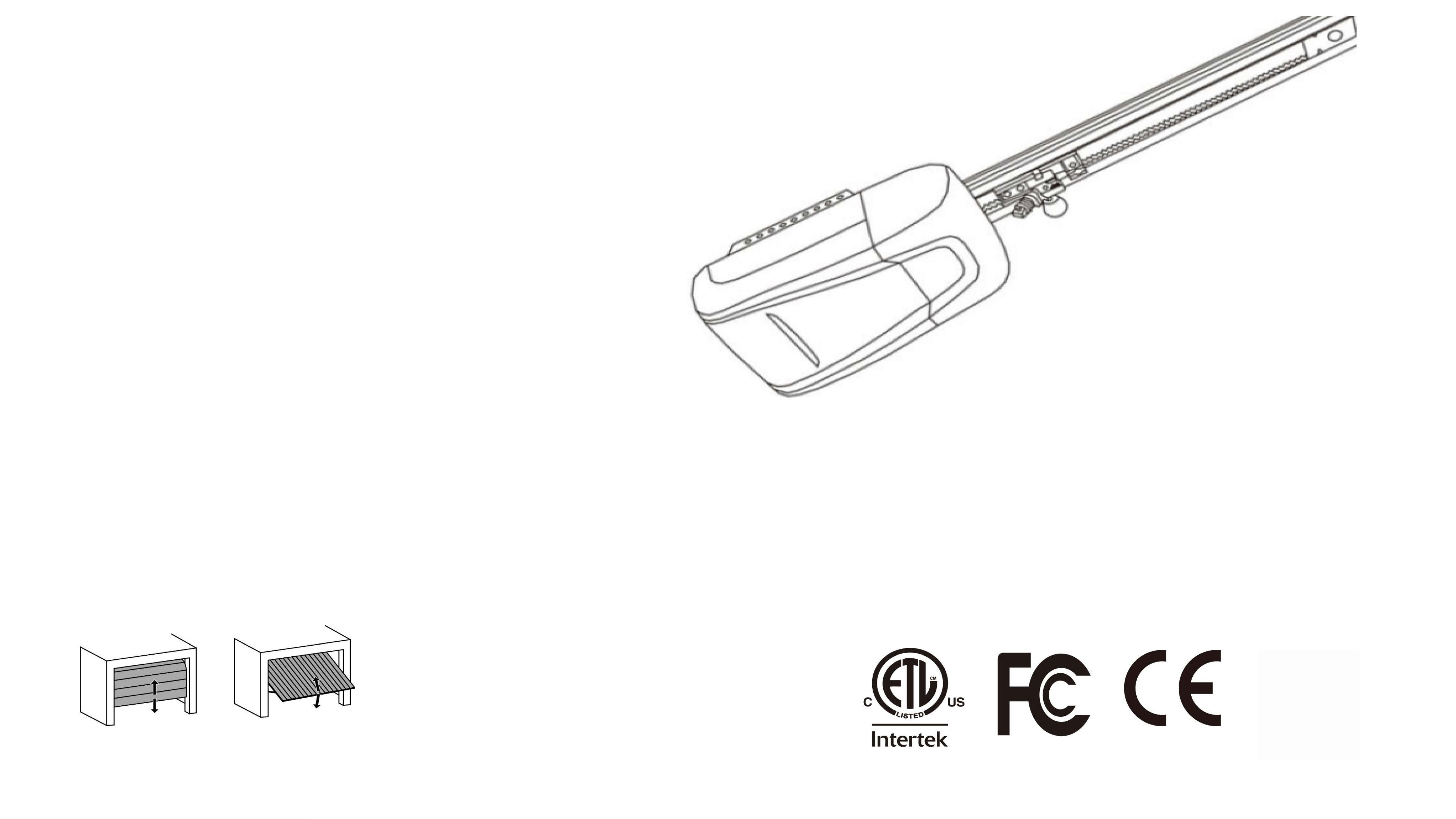
User Manual
Garage Door Opener
High Peormance I Intelligent Control I
Multi-Platform Compatibility
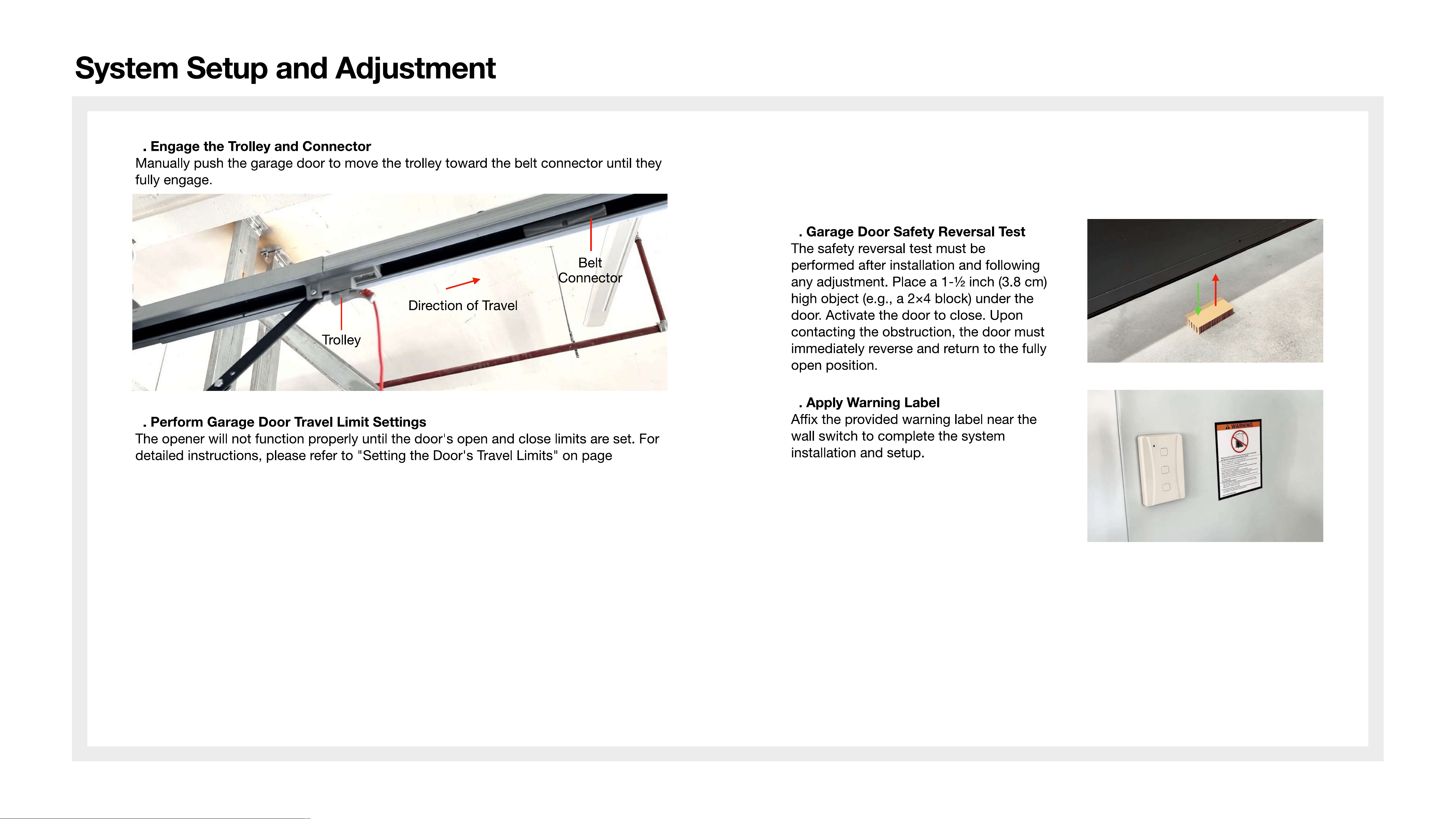
System Setup and Adjustment
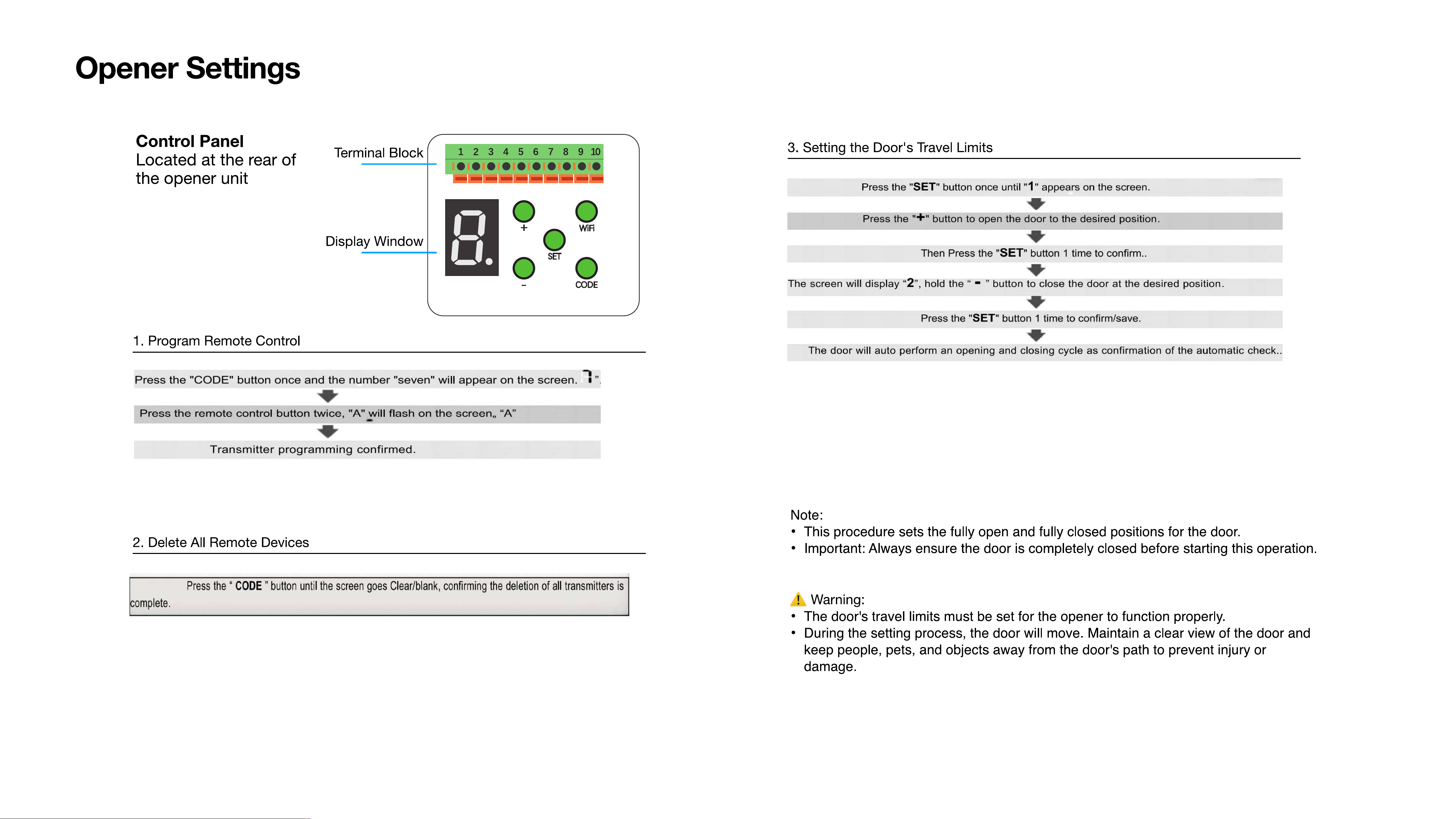
Opener Settings
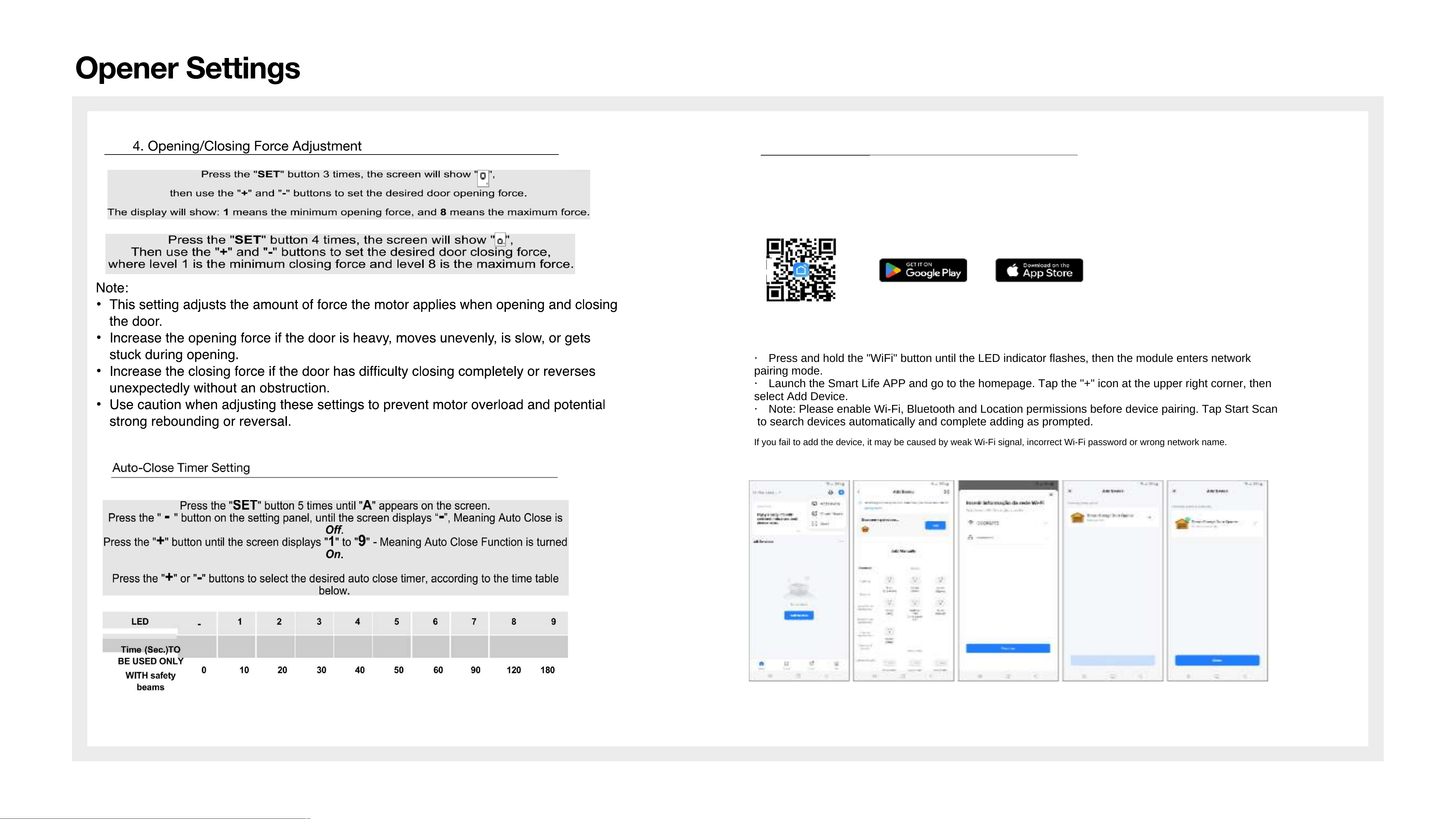
-15
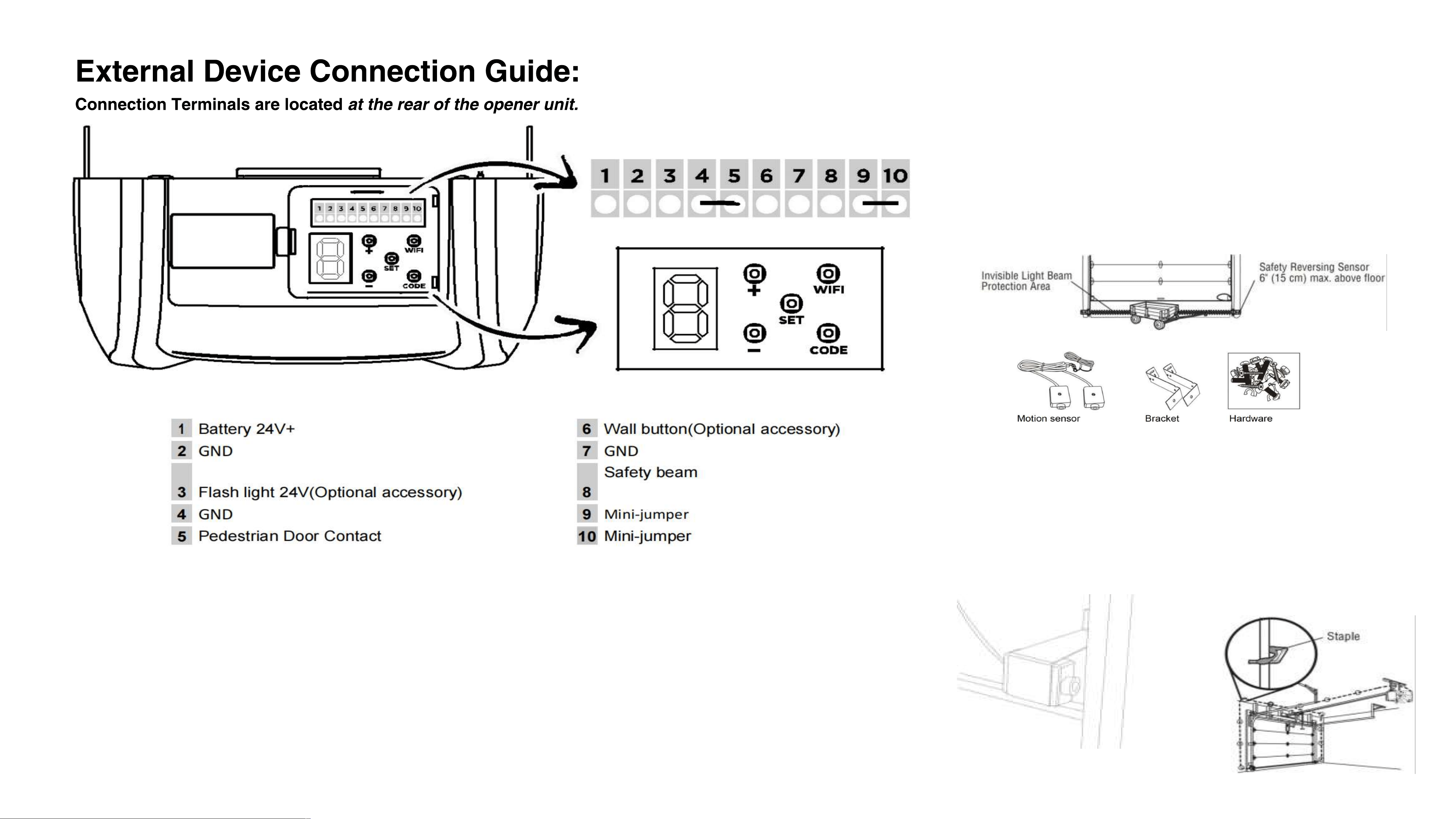
External Device Connection Guide............................................
16
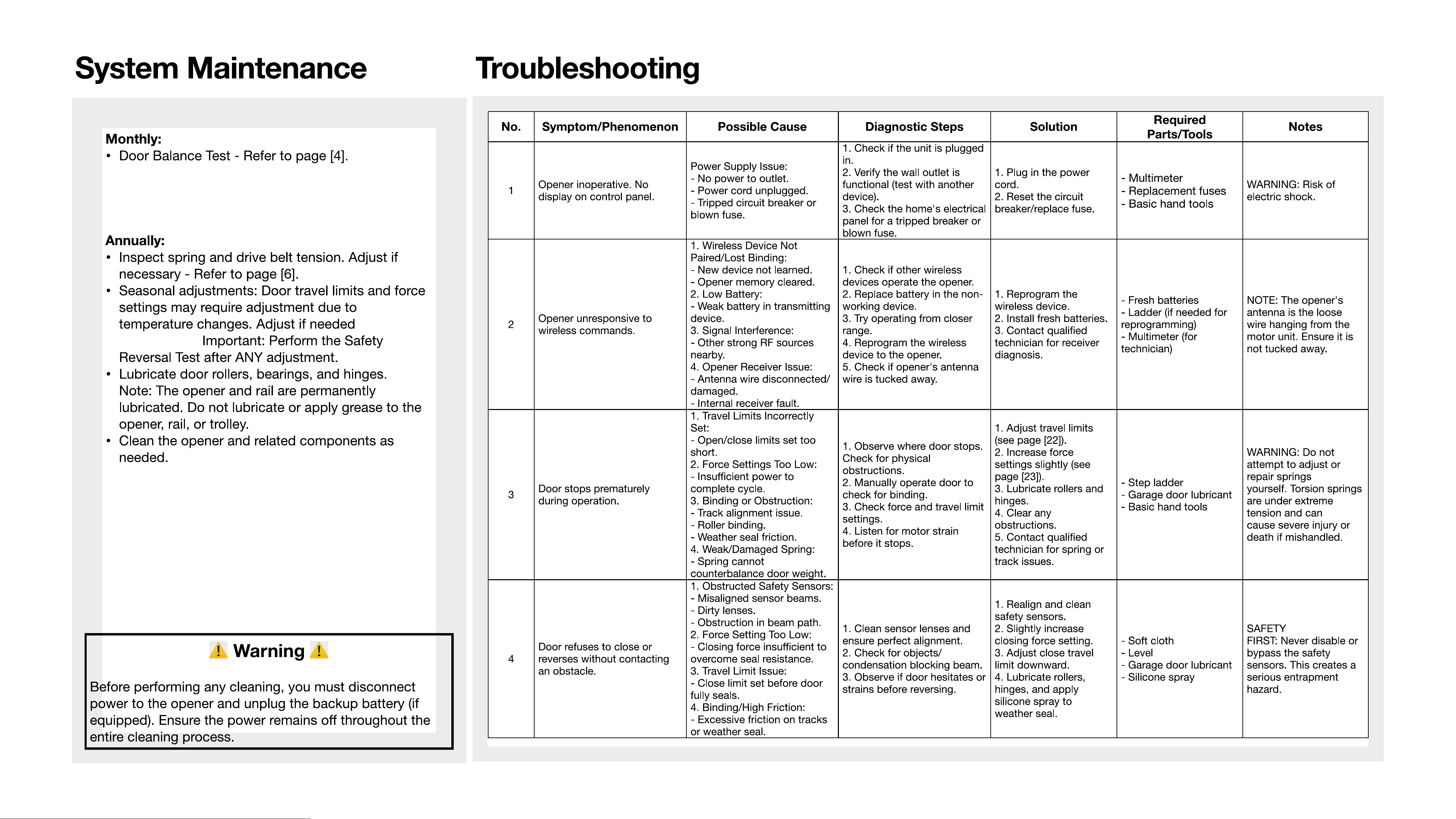
System Maintenance............................. 17
Troubleshooting........................................................................ 17
Warranty Terms ........................................................................ 18
T
e
c
h
n
i
ca
l
S
p
ec
i
f
i
ca
t
i
ons
:
P
r
o
d
uc
t
O
v
e
r
v
i
e
w
M
o
d
e
l
N
u
m
b
e
r
P
u
ll
a
n
d
P
u
s
h
F
o
r
c
e
M
o
t
o
r
V
o
l
t
a
g
e
V
o
l
t
a
g
e
S
p
ee
d
Z
T
Q-1
/2HP
800
N
T
em
p
e
r
a
t
u
r
e
R
a
n
g
e
2
4
V
D
C
110
V
,60Hz
ZTQ-3/4HP
1
000
N
2
4
V
D
C
11
0
V
,
60
HZ
4.7 in/s
-
2
0
℃
~
+
4
5
℃
-
2
0
℃
~
+
4
5
c
R
e
m
o
t
e
C
on
t
r
o
l
C
o
d
e
433
.
9
2
M
H
Z
433
.
9
2
M
H
Z
R
emo
t
e
B
a
tt
e
r
y
V
o
t
t
a
g
e
12
V
,
2
7
A
1
2
V
,
2
7
A
1
、
L
a
m
p
s
h
a
d
e
2
、
L
ED
P
C
B
3
、
M
a
i
n
H
o
u
s
i
n
g
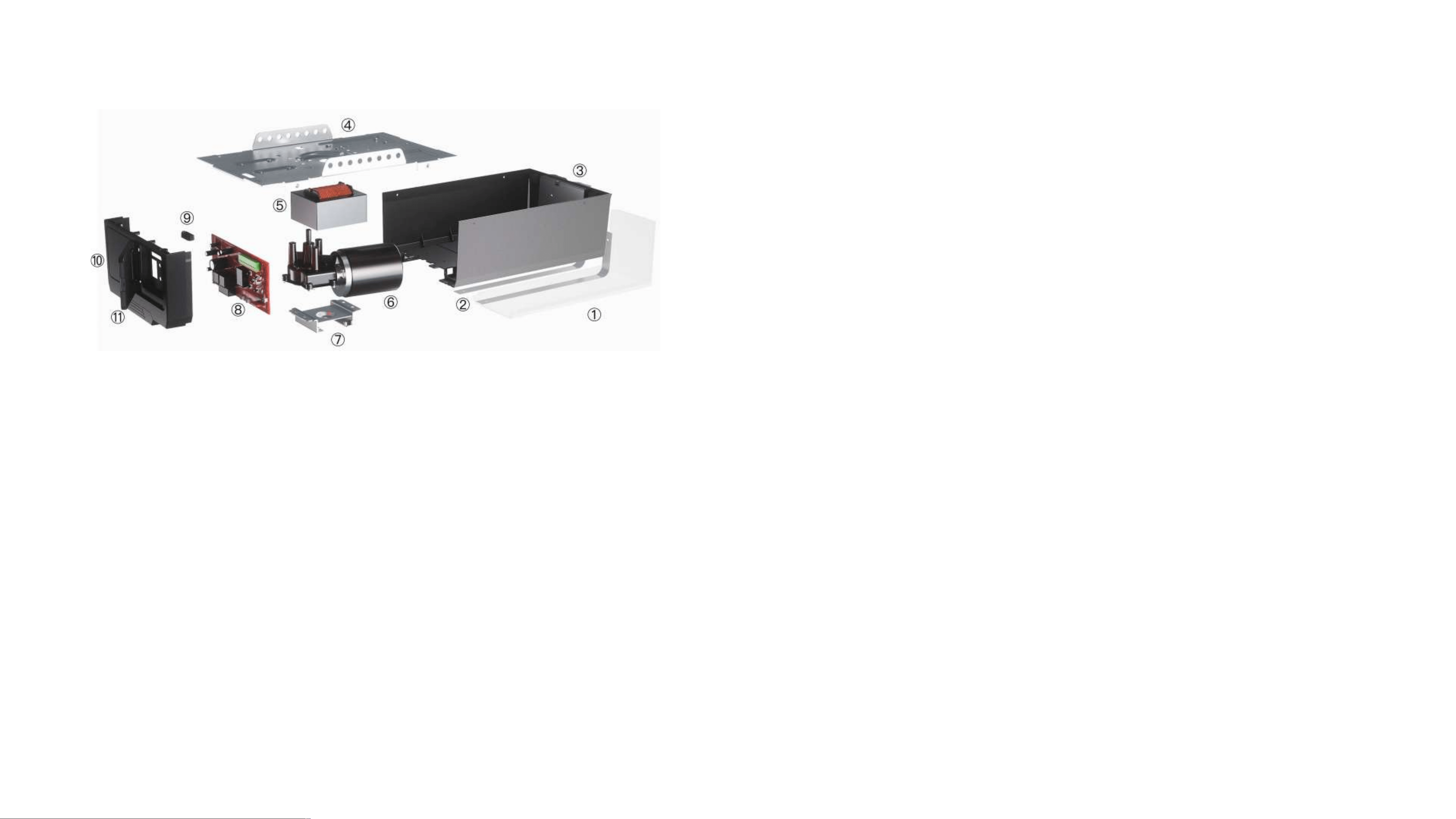
4
、
B
ase
P
l
a
t
e
5
、
T
r
a
n
s
f
o
r
m
e
r
6
、
D
C
M
o
t
o
r
7
、
T
ra
n
s
f
o
r
m
e
r
B
r
ac
k
e
t
8
、
M
a
i
n
P
C
B
9
、
W
i
r
e
A
cc
e
ss
H
o
l
e
1
0
、
R
e
a
r
C
o
v
e
r
1
1
、
F
l
i
p
C
o
v
e
r
C
o
d
i
n
g
F
o
r
m
a
t
R
o
l
l
i
n
g
C
o
d
e
R
o
l
l
i
n
g
C
o
d
e
R
e
m
o
t
e
D
i
s
t
a
n
ce
(
I
n
O
p
e
n
A
r
e
a
)
Note:This product is only suitable for garage doors with a height of up to 7 ft (2.1 m)
1
ApplyDoor Area
164 ft
Max Door Weight
220 l
4.7 in
129 sq108 sq
164 ft
ft ft
/s
b
Spring Balanced Weight
176 lb
66 lb
77 lb
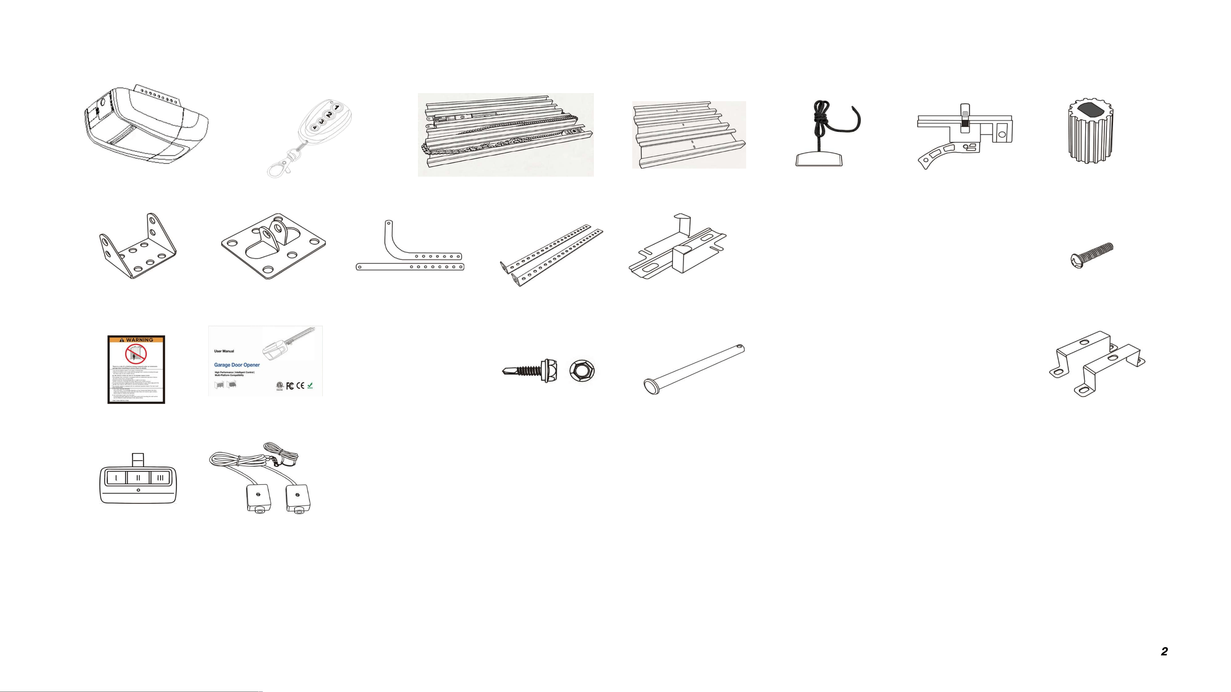
What•s in the Box
Motor bushingC Ra cnectorGarage door opener
X1
C Rail assembly
X4 X3
U-shape clamps
X2
X1
L-shaped hange
Door brac
Hear bract
X1
tX1
rX2
C-rail hanger
X1
Long clevis pin
Door arms
(curved and straight)
'
邸
Warning label
(
User manual x 1
MB
X
20Scre
+nuts x6
M5x25 Screws x 4
X1
Pu cord
X1
哼
M6x
8
Flange
screws
x
4
`
Short clevis pins x 2
M6x25 Screws
C Ra troey
X1
守
M4x20 screws x3
了R-c/ips x3
x 4
2
Remote controls x 2
Remote control x 1
Wired Safety BeamX1set
E
nsu
r
e
G
a
r
a
g
e
D
o
o
r
i
s
i
n
S
a
f
e
C
o
n
d
i
t
i
o
T
e
s
t
i
n
g
Y
o
u
r
G
a
r
a
g
e
D
oo
r
T
o
o
l
s
R
e
q
u
i
r
e
d
f
o
r
I
n
s
t
a
l
l
a
t
i
o
n
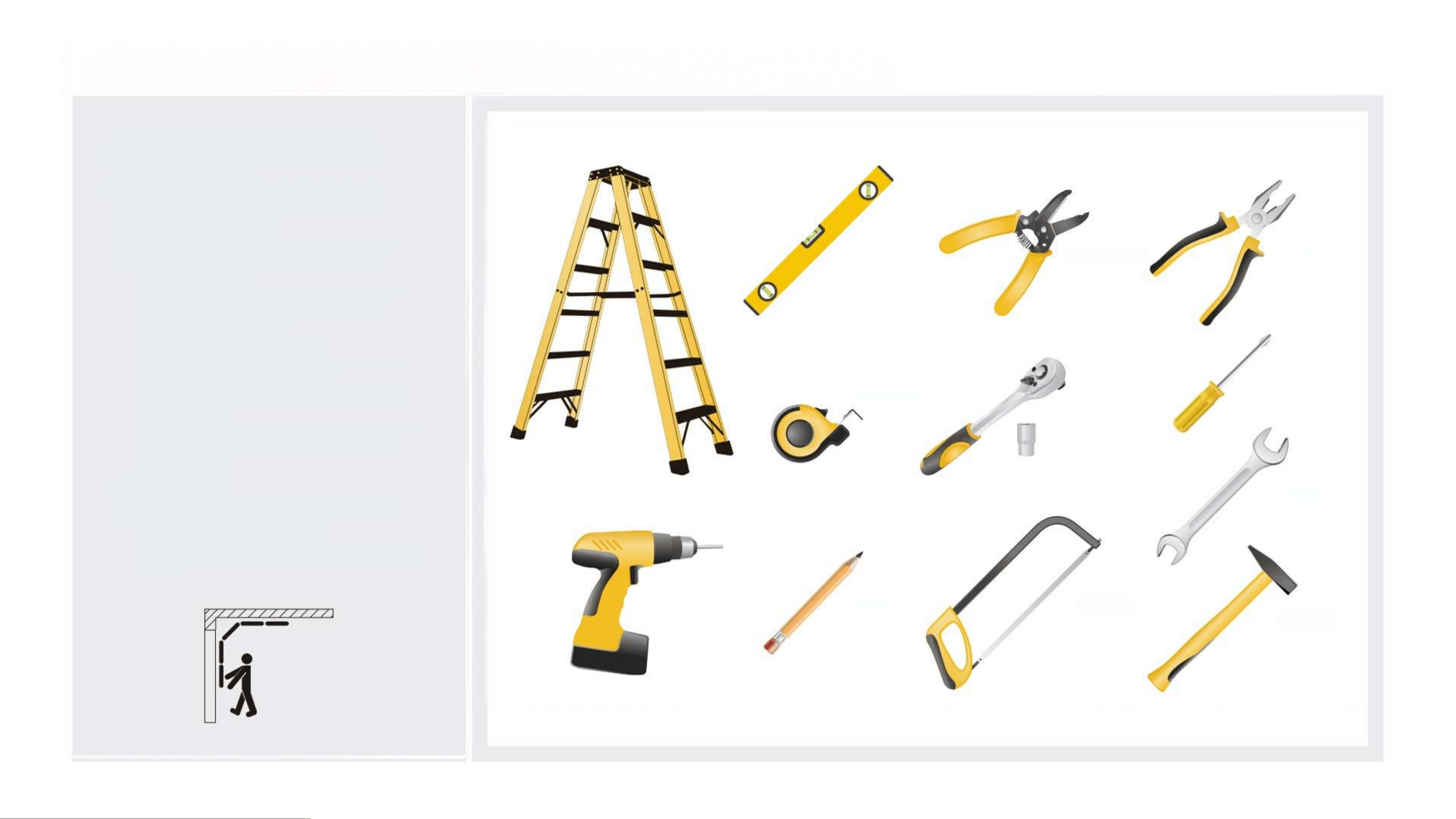
(Tools are not provided)
n
·
E
ns
ur
e
t
h
e
g
a
r
a
g
e
d
oo
r
i
s
f
u
l
l
y
d
l
ose
d
b
e
l
o
r
e
b
e
g
i
nn
i
n
g
i
n
s
t
a
l
l
a
t
i
o
n
.
·
D
i
sa
b
i
e
a
l
l
d
oo
r
l
oc
k
s
an
d
r
emo
v
e
t
h
e
t
r
o
l
l
e
y
(
di
sconnec
t
i
n
g
i
t
f
r
om
an
y
ex
i
s
t
i
n
g
o
p
ener
)
.
L
a
dd
er
G
a
r
a
g
e
D
oo
r
B
a
l
an
ce
T
e
s
t
·
P
e
r
f
o
r
m
t
h
e
f
o
ll
o
w
i
n
g
t
es
t
s
t
o
v
e
r
i
l
y
t
h
e
d
oo
r
i
s
p
ro
p
e
r
l
y
b
a
l
a
nc
e
d
a
n
d
f
u
nc
t
i
o
n
i
n
g
c
o
r
re
c
t
l
y
:
(
a
)
O
p
e
r
a
ti
o
n
T
e
s
t
√
M
a
n
u
a
ll
y
o
p
e
n
a
n
d
c
l
ose
t
h
e
g
a
r
a
g
e
d
oo
r
t
o
c
h
e
c
k
f
or
sm
oo
t
h
,
bi
n
di
n
g
-
f
r
ee
o
p
e
r
a
i
i
o
n
.
(
b
)
C
o
m
p
o
nen
t
I
n
s
p
ec
t
i
o
n
√
C
o
n
f
i
r
m
a
ll
h
i
n
g
es
a
r
e
se
c
u
r
e
y
C
h
ec
k
t
h
a
t
a
ll
f
o
l
l
e
r
s a
r
e
i
n
g
o
o
d
co
n
d
l
t
i
o
n
√
I
n
s
p
ec
t
ca
b
l
es
f
o
r
s
i
g
n
s
o
f
w
ea
r
y
V
e
r
i
t
y
s
p
i
n
g
s
s
h
o
w
n
o
f
a
i
g
u
e
o
r
b
r
ea
k
a
g
e
(
c
)
B
a
l
a
nce
T
e
s
t
√
L
i
f
t
t
h
e
d
oor
t
o
t
h
e
h
a
l
f
wa
y
-
o
p
e
n
p
os
i
t
i
on
a
n
d
r
e
l
e
a
s
e
-
a
p
ro
p
er
l
y
b
a
l
a
nce
d
d
oo
r
s
h
o
u
l
d
r
ema
i
n
i
n
p
l
ace
.
W
i
r
e
s
t
r
i
pp
er
L
e
v
e
l
P
l
i
e
r
S
c
r
e
w
d
r
i
v
e
r
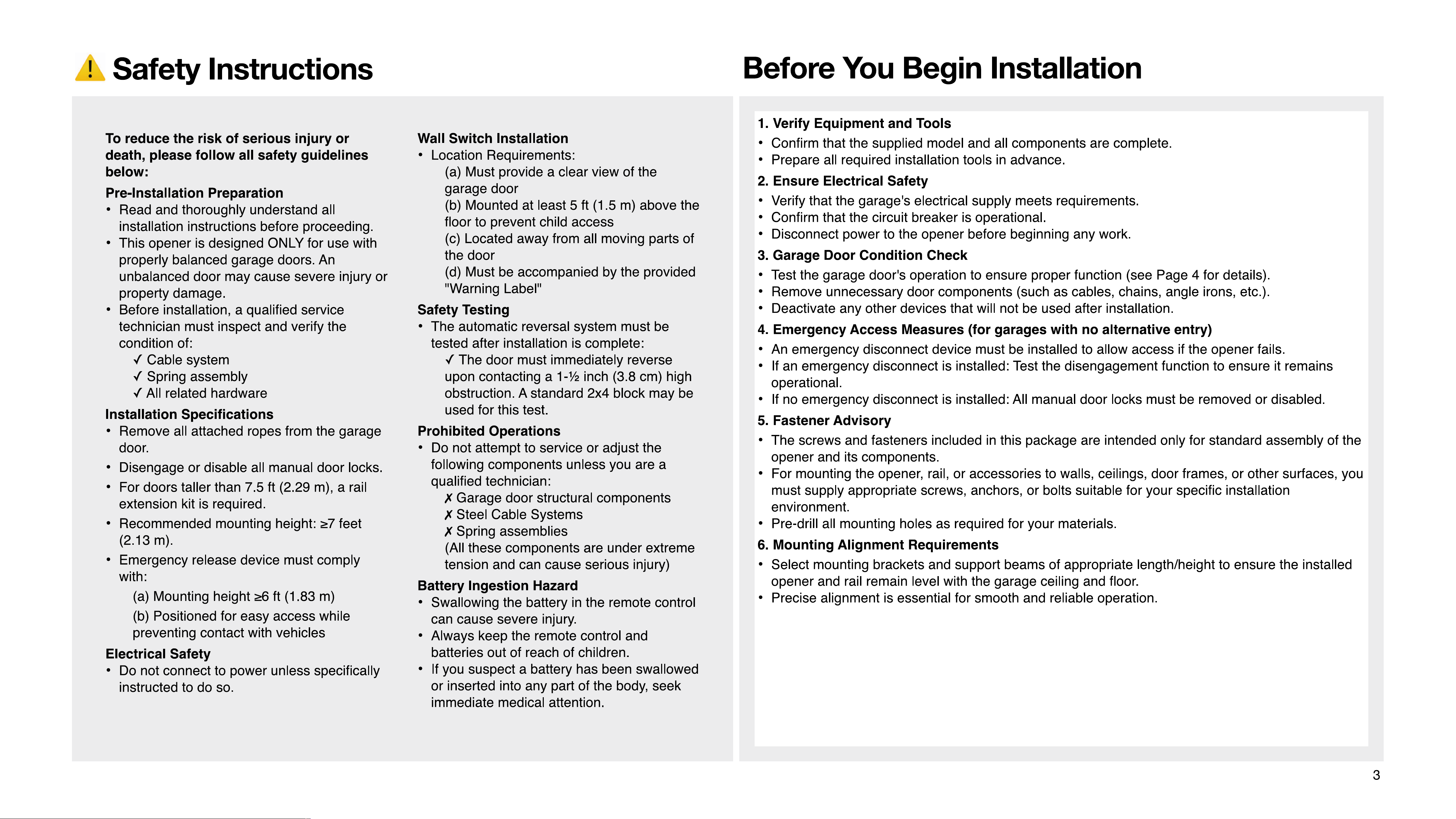
T
a
p
e
me
a
su
r
e
S
oc
k
e
t
w
re
n
c
h
se
t
I
f
l
ss
u
e
s
A
r
e
F
o
u
n
d
W
r
e
n
c
h
·
I
f
y
o
u
o
b
se
r
ve
an
y
ro
u
g
h
o
p
e
r
a
t
i
o
n
,
d
a
m
a
g
e
d
co
m
p
o
nen
t
s
,
o
r
b
a
l
an
c
e
p
r
o
b
l
ems
:
√
S
t
o
p
i
ns
t
a
ll
a
t
i
o
n
i
mm
e
d
i
a
t
e
l
y.
√
C
on
i
ac
t
a
q
u
a
l
l
f
i
e
d
g
a
r
a
g
e
d
oo
r
t
ec
h
n
i
c
i
a
n
f
o
r
se
r
v
i
c
e
.
P
e
n
c
i
l
P
o
w
er
d
r
ll
H
a
c
k
s
a
w
H
a
m
m
e
r
4
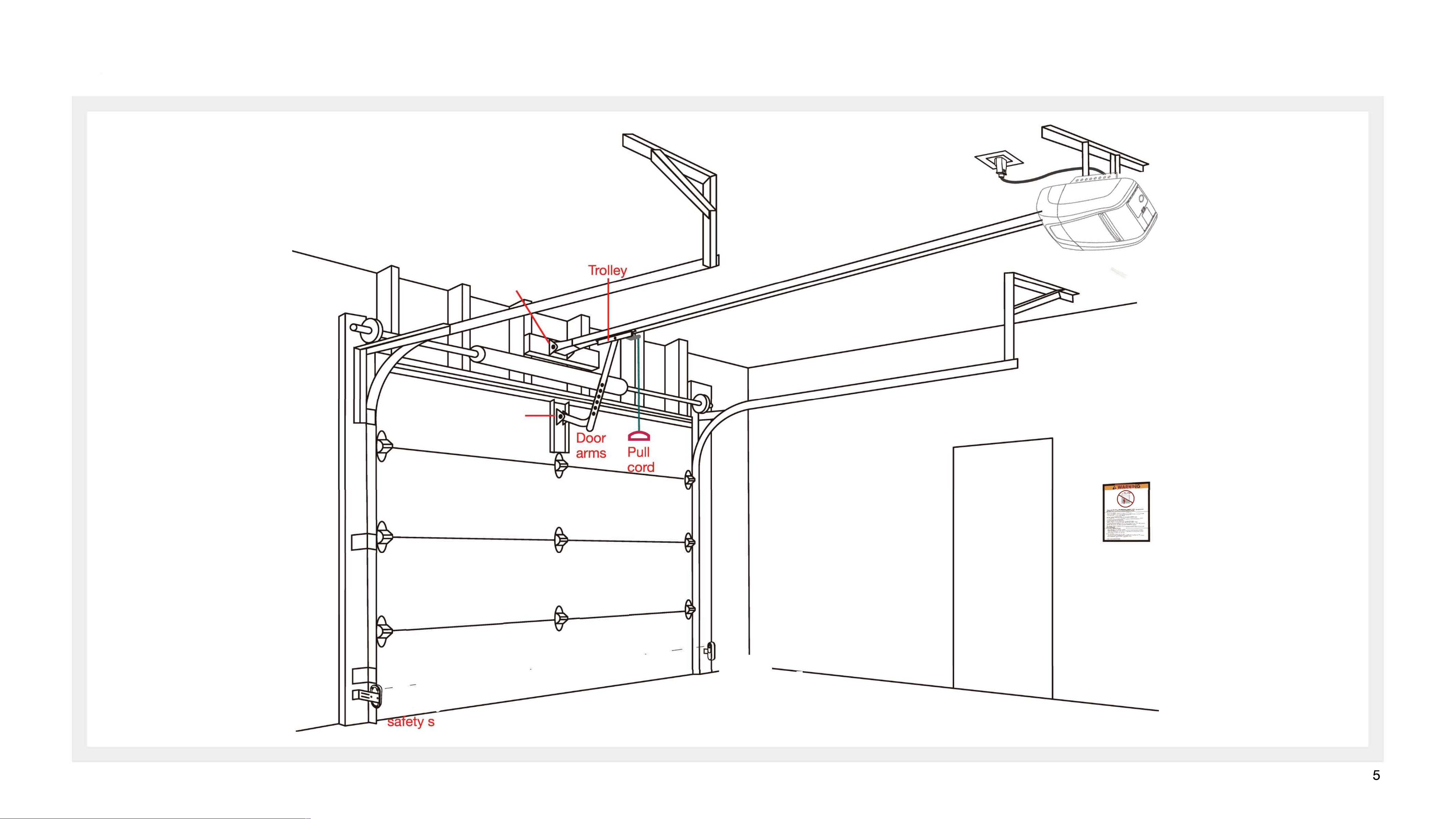
Installation Diagram
Header
bracket
Opener
CRail
Door
bracket
--
-
i
-lI}
i
_
_
鲁
一
-i
i
-
__
_-
-
-
『
-
-
-
-
__
i-i}
宝}}_}___
。
Warning
label
_
--
-
-
_
_
_
_
_
_
_
_
_
森
safety sensor
ensor
5
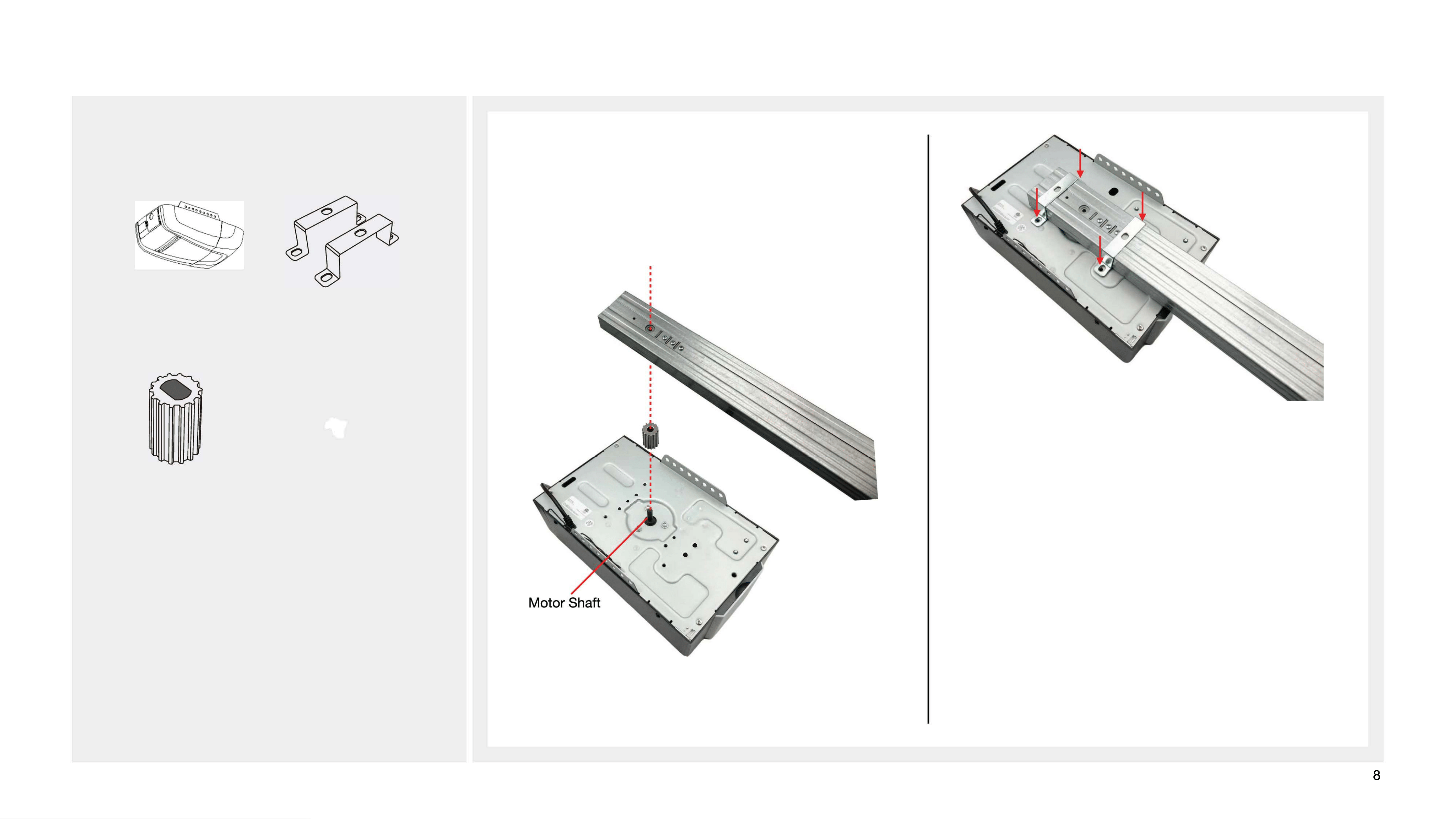
Assembling the Motor Unit and Rail
Locate in the packaging box:
1. Place the door opener with its baseplate facing upward
on a clean, soft surface. As shown in the diagram,
assemble the motor bushing and C-rail section 1 onto the
motor shaft.
Opener
-shaped clamps
寻
Motor bushing
_
M6x8 Flange screws x 4
IIIIIIII
.
g
,
.
.
.
.
.
心
.
.
.
2. Using four M6x9 flange screws and a U-clamp, secure
the C-rail to the opener base plate in the direction indicated
by the arrows.
8
(Pay attention to the
direction)
13
14
(Wall switch is optional accessory)
14
5.
15
closed
6, WiFi Connection
Install Smart Life APP
Download and install the Smart Life APP via Google Play,
Apple App Store or scan the QR code below,then complete user registration.
Add A Device
· Press and hold the "WiFi" button until the LED indicator flashes, then the module enters network
pairing mode.
· Launch the Smart Life APP and go to the homepage. Tap the "+" icon at the upper right corner, then
select Add Device.
· Note: Please enable Wi-Fi, Bluetooth and Location permissions before device pairing. Tap Start Scan
to search devices automatically and complete adding as prompted.
If you fail to add the device, it may be caused by weak Wi-Fi signal, incorrect Wi-Fi password or wrong network name.
16
(Optional)
(Normally Closed)
4.5 Pedestrian Door Connection Status
Terminal 5 is the Pedestrian Door Contact(NC). When the door is closed, the contact remains closed and the device detects a normal signal.
When the door opens, the contact opens, triggering the protection logic.
9.10 Infrared Safety Beam Connection Status
Terminal 8 is the Safety Beam(Infrared) interface. When the infrared function is enabled, connect the safety beam device to Terminal 8
and adjust the mini-jumpers on Terminals 9 and10 as required. When disabled, disconnect Terminal 8 wiring and short the corresponding jumper.
Safety Beam Installation
Before installing the photocell sensors, please confirm the following
requirements:
1) Install two sensors inside the garage, one on each side of the door.
2) Align the two sensors face to face, and ensure the receiving sensor lens
avoids direct sunlight.
3)Mount the sensors no higher than 6 inches (15 cm) above the ground, and
keep the light beam free of obstructions.
PARTS INCLUDED
The Safety Beam shall be mounted on the door track, and installed no more than
6 inches(15 cm) above the floor.
Step 1 Install the Safety Beam
Fit sensor brackets on both sides of the
door, then fix the photocell sensors onto
the brackets with screws. Ensure the
lenses are aligned correctly, and keep
direct sunlight away from the receiving
sensor lens.
Step 2 Wire the Safety Beam
1) Route cables from both sensors to the
garage door opener. Secure the cables to
walls and ceilings using cable staples.
2) Sort out the wires, then connect them
together with the shorting pin to the
corresponding external terminals of the
opener as shown below.
17
The manufacturer hereby warrants to the original purchaser that this product is free from defects in materials and workmanship under the following terms:
1. Warranty Period
2. Service Proces
• 2 -Year warranty on Hardware, including Rail, Chain or Belt, internal motor, and transformer.
1-year warranty on electronic parts, including opener main control board, remote controls, and external wireless accessories from the original date of purchase.
s
•A valid proof of purchase is required for all warranty service.
•If the product must be returned to the manufacturer for service, the purchaser is responsible for all shipping costs both ways.
If any issues arise during the warranty period, the necessary replacement parts will be provided free of charge and delivered with the next shipment.
3. Product Changes
•The manufacturer reserves the right to make changes to current and future products without
obligation to modify previously manufactured units.
4. Warranty Validation
•This warranty is valid only if the product has been installed according to the manufacturer's official installation
instructions.
5. Limitations
This warranty does not cover defects, damage, or failures resulting from:
•Lack of or improper preventive maintenance or adjustment.
•Continued use after a known defect is apparent.
•Unauthorized modification, alteration, or repair.
•Acts of God, force majeure, or external causes such as power surges.
6. Non-Covered Items
•Consumable parts (e.g., batteries, fuses).
•Sensitivity adjustment services.
7. Voiding Conditions
This warranty is void if the product is damaged due to:
•Water damage, moisture, or condensation.
•Electrical power faults or surges.
•Natural disasters or acts of God.
•Service or modification by unauthorized personnel.
•Radio frequency interference.
•Failure to perform required maintenance.
Warranty Terms and Condition
18
s

FCC Warning
This device complies with Part 15 of the FCC Rules. Operation is subject to the following two conditions:
(1) This device may not cause harmful interference, and (2) this device must accept any interference received, including
interference that may cause undesired operation.
NOTE 1: This equipment has been tested and found to comply with the limits for a Class B digital device, pursuant to part 15 of
the FCC Rules. These limits are designed to provide reasonable protection against harmful interference in a residential
installation. This equipment generates, uses and can radiate radio frequency energy and, if not installed and used in accordance
with the instructions, may cause harmful interference to radio communications. However, there is no guarantee that
interference will not occur in a particular installation. If this equipment does cause harmful interference to radio or television
reception, which can be determined by turning the equipment off and on, the user is encouraged to try to correct the
interference by one or more of the following measures:
- Reorient or relocate the receiving antenna.
- Increase the separation between the equipment and receiver.
-Connect the equipment into an outlet on a circuit different from that to which the receiver is connected.
-Consult the dealer or an experienced radio/TV technician for help.
NOTE 2: Any changes or modifications to this unit not expressly approved by the party responsible for compliance could void the
user's authority to operate the equipment.
RF Exposure Statement
To maintain compliance with FCC'S RF Exposure guidelines, This equipment should be installed and operated with minimum
distance of 20cm between the radiator and your body. This device and its antenna(s) must not be co-located or operation in
conjunction with any other antenna or transmitter.

