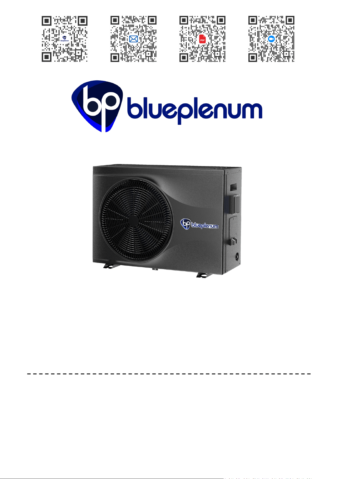
INVERTER POOL HEAT PUMP USER MANUAL
This manual contains critical information regarding safety, operation, maintenance, and
storage. To prevent severe personal injury or property damage, read and fully understand
all instructions and safety precautions prior to installation or use. Improper operation may
result in personal injury or equipment damage.
Official Store Email Us PDF (EN & ES Version) Tutorial Video

CONTENTS
support@blueplenum.com | www.blueplenum.com | BluePlenum All Rights Reserved
1
1. SAFETY GUIDELINES ........................................................................................................................... 2
2. UNPACKING INSPECTION ................................................................................................................... 6
3. INSTALLATION .....................................................................................................................................11
3.1 HANDLING AND TRANSPORT ......................................................................................................11
3.2 INSTALLATION SITE SELECTION ................................................................................................ 12
3.3 PRE-INSTALLATION CHECKLIST .................................................................................................14
3.4 CONDENSATE DRAINAGE INSTALLATION ................................................................................ 15
3.5 PLUMBING INSTALLATION ...........................................................................................................16
3.6 ELECTRICAL INSTALLATION ....................................................................................................... 22
3.7 POST-INSTALLATION TESTING ...................................................................................................24
4. CONTROL PANEL OPERATION ......................................................................................................... 27
5. APP CONTROL .................................................................................................................................... 38
5.1 PREPARATION BEFORE CONNECTING .....................................................................................38
5.2 LAUNCH THE TUYA SMART APP .................................................................................................39
5.3 PAIRING METHOD ......................................................................................................................... 40
5.4 TUYA SMART APP FUNCTIONS ...................................................................................................48
6. TROUBLESHOOTING ..........................................................................................................................49
7. MAINTAINANCE ................................................................................................................................... 51
7.1 WINTERIZING...................................................................................................................................51
7.2 ROUTINE CLEANING PROCEDURES.............................................................................................. 51
7.3 ANNUAL INSPECTIONS.................................................................................................................. 52
8. WARRANTY ..........................................................................................................................................53
8.1 TWO-YEAR WARRANTY ............................................................................................................... 53
SAFETY GUIDELINES
support@blueplenum.com | www.blueplenum.com | BluePlenum All Rights Reserved
2
1. SAFETY GUIDELINES
1.1 IMPORTANT: RETAIN THIS MANUAL FOR FUTURE REFERENCE
This manual contains critical information regarding safety, operation, maintenance, and
storage. To prevent severe personal injury or property damage, read and fully
understand all instructions and safety precautions prior to installation or use.
Improper operation may result in personal injury or equipment damage.
Note: Illustrations in this manual are for reference only. The actual product may vary due
to enhancements or model specifications. Refer to the actual product for precise details.
Design and specifications are subject to change without notice.
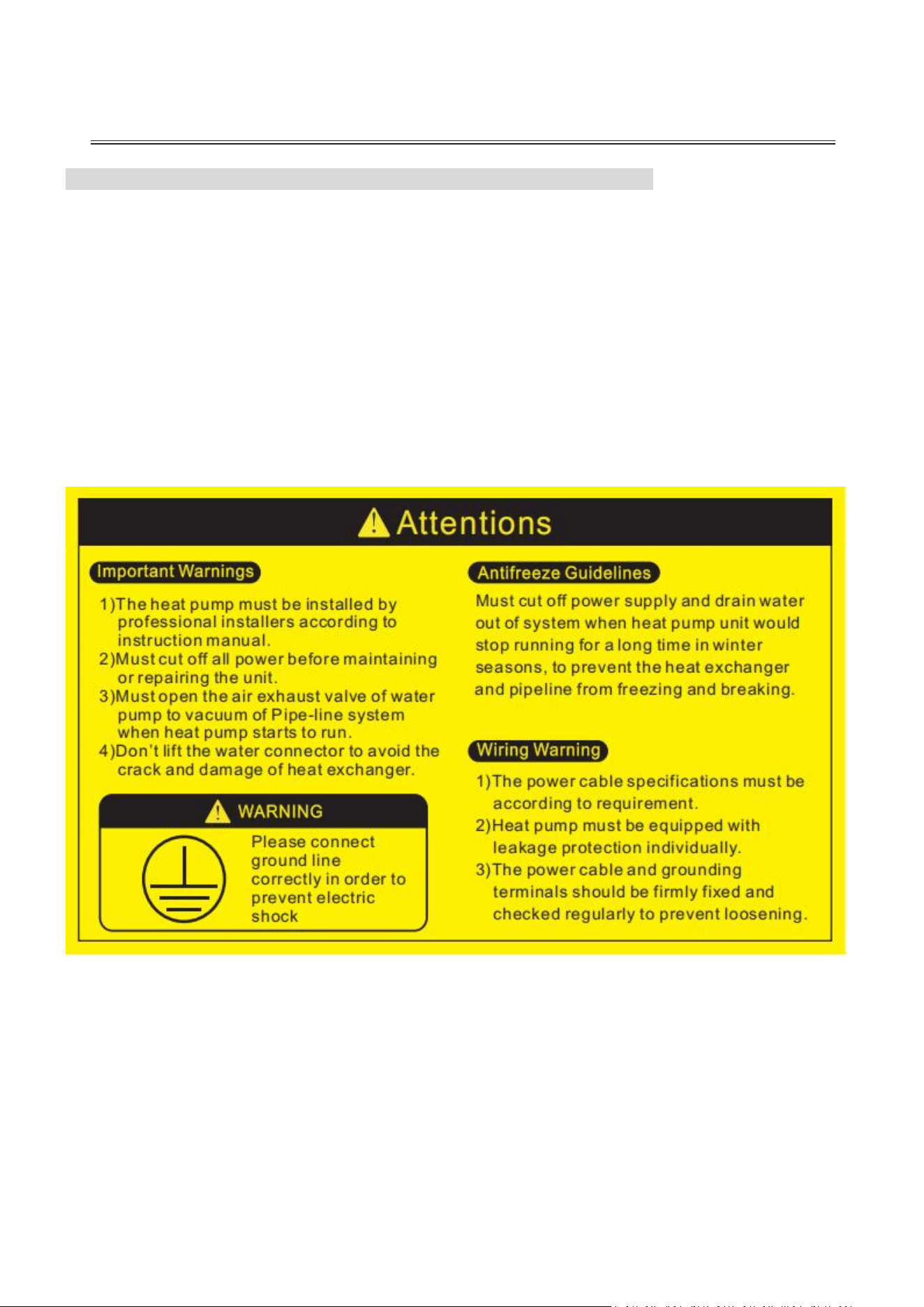
To ensure the safety of personnel and property, strictly adhere to the following
directives:
1. Compliance: Ensure all installations comply with local codes, regulations, and
standards. Only a qualified technician should install, remove, or service the unit.
2. Power Supply: Verify that the power supply matches the specified voltage and
frequency of the unit.
3. Grounding: The unit must be reliably grounded before use; failure to do so may result
in serious injury or death.
SAFETY GUIDELINES
support@blueplenum.com | www.blueplenum.com | BluePlenum All Rights Reserved
3
4. Safe Handling: Refrain from handling the unit with wet hands to prevent electric
shock. Avoid connecting or disconnecting the power while the unit is in operation.
5. Dedicated Circuit: This unit requires a dedicated branch circuit. A dedicated
HACR-rated (Heating, Air Conditioning, and Refrigeration) circuit breaker is required
for this installation.
6. Leakage Protection: A certified Class A Ground Fault Circuit Interrupter (GFCI) must
be installed and securely connected to prevent electric shock or fire.
7. Emergency Protocol: Read all product labels carefully. In the event of abnormalities
—including unusual noise, odors, smoke, excessive heat, or electrical leakage
—immediately disconnect the power. Promptly contact our Service Center for
repairs. In case of fire, alert local emergency services and ensure a dry powder or CO2
fire extinguisher is nearby.
8. Winterizing: when the unit is running at an ambient temperature below 32℉, DO NOT
disconnect the power supply. The unit requires constant power to activate its
automatic anti-freeze protection, which runs the compressor or water pump to
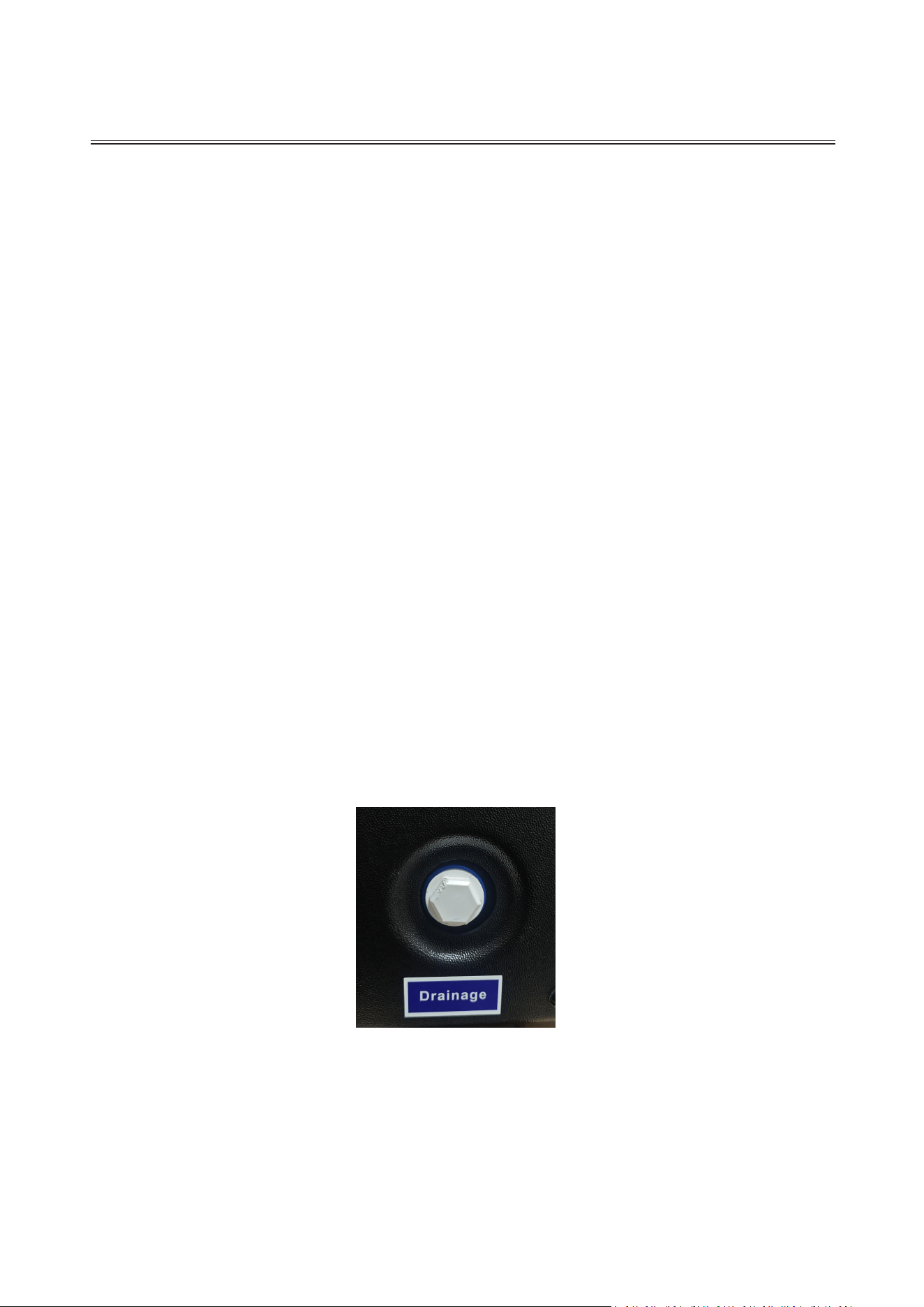
prevent system damage. If the heat pump is decommissioned during winter, use a
wrench to unscrew the drainage cap on the side of the unit (see figure below) and
drain all water completely.
Note: Some models have removed the drainage port due to upgrades; the water inside the
unit can be drained directly through the water inlet and outlet.
This prevents freezing and expansion, which can lead to internal pipe bursts and severe
system damage. Do not use unapproved methods (like open flames) to accelerate
defrosting.
9. Water Flow: Never operate the unit without verified water flow. The pool pump must
be active and circulating water through the heat pump during operation.
10. Pump Strainer: To prevent debris from damaging the system, install a pump strainer

SAFETY GUIDELINES
support@blueplenum.com | www.blueplenum.com | BluePlenum All Rights Reserved
4
(hair/lint collector) upstream of the water pump. Alternatively, use a pump with an
integrated strainer basket.
11. Sand Filter: A sand filter must be installed downstream of the water pump to
remove fine impurities and ensure clear water flows into the heat pump.
1.2 CAUTIONARY NOTES
1. Installation & Environment
Foundation Requirements: Ensure the unit is mounted on a level, solid, and secure
surface. An improperly secured unit poses a risk of falling, excessive vibration, or
structural damage.
Materials: Always utilize appropriate, high-quality installation materials. Using
incorrect components can result in fire or the unit dropping.
Grounding: The unit must be reliably grounded. NEVER connect the grounding wire
to gas pipes, water pipes, lightning conductors, or telephone lines, as this creates a
severe risk of explosion or fatal electric shock.
Physical Safety: Handle the unit cautiously when unpacked. Beware of the sharp
edges and fins on the heat exchanger to avoid cuts.
Ventilation Safety:
In confined spaces, ensure adequate airflow to prevent suffocation in the event
of a refrigerant leak.
Keep Hands Clear: Do not reach into the ventilation openings. High-speed fan
blades and electrical hazards are present. Failure to comply may result in severe
personal injury.
Drainage Management: Follow all guidelines for drainage pipes. Faulty systems must
be fixed immediately to avoid water damage to nearby property.
Refrigerant Awareness(R32): This unit utilizes R32, an eco-friendly and
energy-efficient refrigerant with a low Global Warming Potential (GWP). Please note
that R32 is classified as a mildly flammable refrigerant. Keep the installation area clear
of open flames, sparks, or other ignition sources during operation or maintenance. No
Smoking signs should be displayed.
Explosive Risks: Do not place the unit in areas with explosive or flammable gases to
avoid explosion risks.
2. Chemical Safety

SAFETY GUIDELINES
support@blueplenum.com | www.blueplenum.com | BluePlenum All Rights Reserved
5
Chemical Balance: All chemical feeding systems or salt chlorinators must be installed
downstream of the heat pump. A check valve is required to prevent concentrated
chemicals from backflowing and corroding the heat exchanger.
3. Electrical Precision
Always utilize professional-grade tools for all electrical work. Turn off the unit before
cleaning or servicing.
All wiring must strictly adhere to the provided Wiring Diagram to prevent component
burnout or fire.
Cables must be securely fastened to the terminal blocks so there is no pulling or
tension on the wire connections. This prevents the wires from becoming loose over
time.
4. Supervision
For safety purposes, this appliance is not intended for unsupervised use by individuals
(including children) who may require additional assistance to operate it safely. Children
should be closely supervised to ensure they do not play with the unit or its controls.
5. Refrigerant Information (R32)
This appliance utilizes R32 refrigerant, a leading solution in high-efficiency cooling
technology.
Safety Profile: R32 is a mildly flammable (A2L class), odorless gas. While it poses a
low ignition risk under normal conditions, it should be kept away from open flames and
extreme heat. Under standard operational parameters, R32 is stable and safe for
residential use.
Environmental Impact: R32 is an eco-friendly choice with Zero Ozone Depletion
Potential (ODP) and a significantly lower Global Warming Potential (GWP)
compared to conventional refrigerants.
Energy Efficiency: Due to its superior thermodynamic properties, R32 delivers high
energy performance with a smaller charge volume, making the unit more efficient and
compact.
UNPACKING INSPECTION
support@blueplenum.com | www.blueplenum.com | BluePlenum All Rights Reserved
6
2. UNPACKING INSPECTION
Upon delivery, please follow these steps to inspect the unit. If any discrepancies or
damage are found, do not proceed with installation and contact our Service Center
immediately.
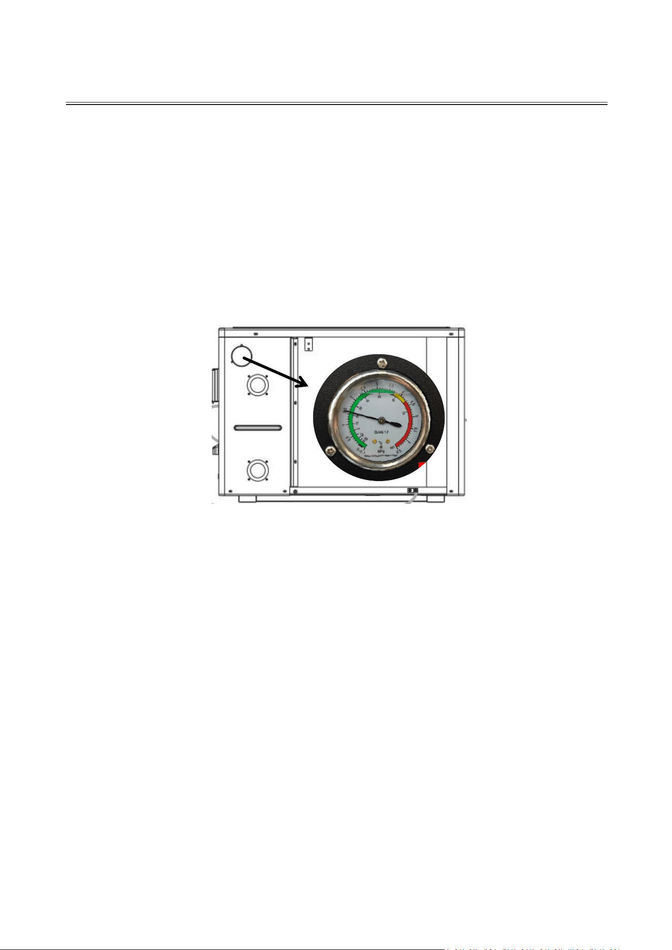
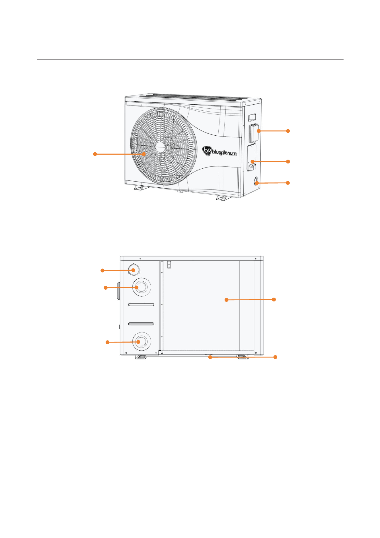
2.1 Check Pressure: Observe the pressure gauge on the back of the unit (see figure
below). The reading should be between 1.0 and 2.0 MPa. If the pressure is outside this
range, there is a risk of refrigerant leakage; please contact our Service Center before
installation. (During operation, pressure gauge readings will fluctuate based on the
unit’s current running status; this is normal and expected behavior.)
2.2 Product Verification: After unpacking, verify that the unit is free from physical
damage and that the model, color, and quantity exactly match your order
specifications.
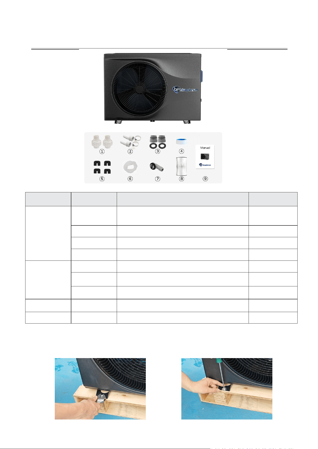
2.3 Check Accessories: Cross-reference all included accessories with the "Packing
List" provided below. Ensure all components are present and undamaged.
UNPACKING INSPECTION
support@blueplenum.com | www.blueplenum.com | BluePlenum All Rights Reserved
7
ITEM NO.
COMPONENT
QUANTITY
Upper Half
①
1.5" (48.3mm) PVC Pipe Converter
[Pre-installed on the unit]
2
②
1.25"&1.5" Hose Adapter & Hose Clamp
2
③
1.5" Adapter Conversion Kit
2
④
Teflon tape
2
Lower Half
⑤
Insulation Mats
4
⑥
Condensate Pipe (2m)
1
⑦
Condensate Pipe Connector
1
Protection
⑧
UV-resistant & Waterproof Cover
1
Guide
⑨
User Manual
1
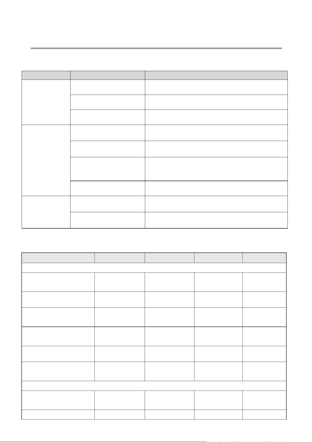
2.4 Removing the Pallet: Use a wrench and screwdriver to unscrew the four shipping
bolts from the support feet (see figures below).Carefully remove the heat pump from the
shipping pallet.
UNPACKING INSPECTION
support@blueplenum.com | www.blueplenum.com | BluePlenum All Rights Reserved
8
2.5 Additional Tools Required for Installation (Not Included)
2.6 System Specification
Model
Flow Pro 48
Flow Pro 58
Flow Max 80
Flow Max 107
Heating Specification
Heating Capacity A80°F/
W80°F/Humid. 80% Max./Min.
48000/17000
BTU/H
58000/22000
BTU/H
80000/30000
BTU/H
107000/45000
BTU/H
Heating Power Input
Max./Min.
2.07/0.3KW
2.49/0.4KW
3.43/0.53KW
4.61/0.82KW
COP A80°F/W80°F/
Humid. 80%
6.8-16.2
6.8-16.2
6.8-16.2
6.8-16.2
Heating Capacity A59°F/
W80°F/Humid. 70% Max./Min.
35000/12000
BTU/H
45000/16000
BTU/H
63000/23000
BTU/H
79000/36000
BTU/H
Heating Power Input
Max./Min
2.28/0.45KW
2.92/0.61KW
4.08/0.86KW
5.12/1.35KW
COP A59°F/W80°F/
Humid. 70%
4.5-7.8
4.5-7.8
4.5-7.8
4.5-7.8
Cooling Specification
Cooling Capacity A95°F/
W85°F/Humid.70% Max./Min.
20130/12283
BTU/H
25181/15354
BTU/H
25249/17811
BTU/H
26102/24157
BTU/H
Cooling Power Input
1.55/0.54KW
1.94/0.67KW
1.95/0.78KW
2.01/1.06KW
Category
Tools
Purpose
General Tools
Wrench
Used to remove the heat pump from the pallet and
to install/replace inlet & outlet adapters.
Screwdriver
Used to remove the unit from the pallet and secure
the heat pump to the foundation.
Expansion Bolts
Used to securely mount the heat pump onto a
concrete base.
Electrical
HACR-rated Circuit
Breaker & GFCI
Provides electrical safety protection against
overloads and ground faults.
#8 AWG Bare Copper
Wire
Used for system grounding and bonding.
Power Cable(Size
based on heat pump
model)
To connect the main power supply to the heat
pump.
Wire Strippers
Used to strip power cables for electrical
connections.
Plumbing
1.5" PVC Pipe or
Flexible Hose
Used to connect the heat pump to the pool water
circulation system.
PVC Adhesive &
Sandpaper
Used to prep pipe joints and complete the sealed
bonding of water pipes.
UNPACKING INSPECTION
support@blueplenum.com | www.blueplenum.com | BluePlenum All Rights Reserved
9
Model
Flow Pro 48
Flow Pro 58
Flow Max 80
Flow Max 107
Max./Min
ERR A95°F/W85°F/
Humid.70%
3.8-6.7
3.8-6.7
3.8-6.7
3.8-6.7
General Specification
Current
12.6A
16.2A
22.9A
30A
Power Supply
208V-240V/1PH/60Hz
Advised Pool Volume (with
pool cover)
13900gaI
16800gaI
22000gaI
28000gaI
Advised Pool Volume
(without pool cover)
10600gaI
13000gaI
18000gaI
24000gaI
Operating Air Temperature
5-109°F
Heating Water Temperature
47-104°F
Cooling Water Temperature
47-83°F
Recommended Flow Rate
22GPM
32GPM
44GPM
59GPM
Noise (33ft)
46db
48db
50db
52db
Compressor
Rotary (Mitsubishi)
Heating Exchanger
TITANIUM HEAT EXCHANGER
Casing
ABS
Water Resistance Class
IPX4
Refrigerant
R32 /1.74Ibs
(27.9oz)
R32/1.87Ibs
(30oz)
R32/2.54Ibs
(40.6oz)
R32/2.87Ibs
(46oz)
Refrigerant CO2 Equivalent
0.53t
0.57t
0.78t
0.88t
Net Unit Size (L/W/H)
35.3" x 15.7" x
25.4"in
35.3" x 15.7" x
25.4"in
41.6" x 17.5" x
29.1"in
41.6" x 17.5" x
29.1"in
Carton Size (L/W/H)
39.0" x 17.1" x
30.3"in
39.0" x 17.1" x
30.3"in
45.1*18.1*34.6in
45.1*18.1*34.6in
Net Weight
95.3lbs
105.5 lbs
155.3 lbs
185.0 lbs
Gross Weight
131.5lbs
141.7lbs
200.8lbs
230.5lbs
INSTALLATION
support@blueplenum.com | www.blueplenum.com | BluePlenum All Rights Reserved
11
3. INSTALLATION
Professional Installation Required: This heat pump must be installed by a
licensed and qualified professional to ensure operational safety and prevent
equipment damage. The instructions provided are for general reference only
and must be adapted to meet local codes and specific site conditions.
3.1 HANDLING AND TRANSPORT
1. Transport & Placement: Transport the unit as close to the installation site as
possible before unpacking.
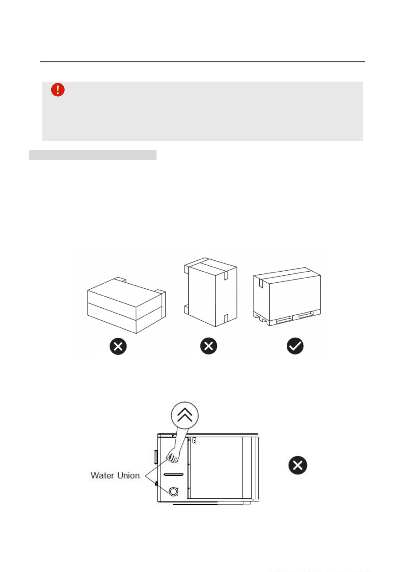
2. Verticality: The heat pump must be kept in an upright position at all times during
storage and transportation. The inclination angle must not exceed 45°. Never store or
move the unit horizontally to prevent damage to the compressor and refrigeration
system.
3. Lifting Restriction: Never lift the heat pump by the water unions or the heat
exchanger, as this will cause severe internal damage.
4. No Stacking: Do not place or store any items on top of the unit.

INSTALLATION
support@blueplenum.com | www.blueplenum.com | BluePlenum All Rights Reserved
12
5. Casing Protection: Do not grip the air outlet grille on the casing, as it is susceptible to
deformation.
6. Fan Safety: Keep hands and foreign objects away from the fan blades at all times to
avoid injury or mechanical failure.
3.2 INSTALLATION SITE SELECTION
To ensure the safety, efficiency, and longevity of the heat pump, please strictly adhere to
the following site selection guidelines:
1. Environmental Constraints
Hazardous Materials: Avoid installation near flammable, explosive, or volatile
materials.
Corrosive & Chemical Exposure: Do not install in areas with high concentrations of
mineral oil, oil mist, salt spray, or sulfur gases. These substances can lead to
component degradation and coil erosion.
Power & Signal Stability: Avoid locations with severe voltage fluctuations. Maintain a
minimum clearance of 9.8ft from equipment emitting strong electromagnetic
radiation (e.g., high-frequency towers) to prevent control interference.
Severe Weather: Avoid areas prone to extreme conditions such as typhoons, heavy
snow drifts, or frequent lightning.
2. Social & Safety Considerations
Traffic & Noise: Do not install near high-traffic roads to prevent mud splashes and
reduce noise interference.
Neighborhood & Safety: Position the unit to minimize noise disturbances to nearby
residents. Ensure the installation is out of reach of children and pets for safety.
3. Location and Spatial Requirements
Accessibility: The site must be easily accessible for effortless operation and regular
maintenance, providing ample space around the unit.
Foundation: Install the unit on a stable, level, and reinforced concrete surface
capable of supporting its weight. If necessary, raise the unit using robust mounting
pads designed to sustain its weight.
Drainage: Position the unit near an effective water drainage system to prevent
potential water damage to the surrounding area.
INSTALLATION
support@blueplenum.com | www.blueplenum.com | BluePlenum All Rights Reserved
13
Ventilation & Airflow: Ensure the site is well-ventilated with no risk of exhaust air
recirculation. Air outlets must not be directed toward nearby windows.
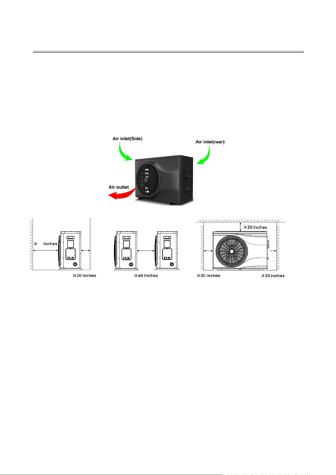
The air inlet or outlet ports are shown in the following figure, carefully following these
installation requirements ensures optimal performance, extends the unit's longevity, and
maintains a safe operating environment for your system:
Front Discharge: Ensure a minimum of 118 inches (3000 mm) of unobstructed
space in front of the unit to prevent air recirculation.
Side-by-Side Installation: When installing multiple units, maintain a minimum
lateral clearance of 40 inches (1000 mm) between each unit.
Rear and Side Intake: Provide at least 20 inches (500 mm) of free space on the
back and both sides of the unit to ensure unimpeded airflow to the evaporator.
Top Clearance: Keep the area above the heat pump completely clear of any
objects or overhangs to allow for vertical heat dissipation and unobstructed
airflow.
118
INSTALLATION
support@blueplenum.com | www.blueplenum.com | BluePlenum All Rights Reserved
14
3.3 PRE-INSTALLATION CHECKLIST
To ensure a smooth and professional installation, please verify the following conditions
and ensure all necessary equipment is prepared:
1. Preliminary Verification
[ ]Equipment Inspection: Confirm the model, quantity, and specifications match your
order. Inspect the casing, evaporator fins, and ports for transport damage, and verify
all included accessories against the packing list.
[ ]Space & Ventilation: Ensure the site has sufficient clearance for maintenance and
that air inlets/outlets are dry, well-ventilated, and unobstructed.
[ ]Structural Foundation: Confirm the mounting surface or foundation is level and has
the load-bearing capacity to support the unit's full operational weight.
2. Electrical Compliance
[ ]Bonding & Grounding: All electrical connections must meet NEC (National
Electrical Code) and local standards. Prepare a #8 AWG bare copper wire for bonding.
This is mandatory for user safety and to prevent galvanic corrosion of the unit’s metal
chassis.
[ ]Power Supply: Voltage, frequency, and capacity must match the unit's nameplate.
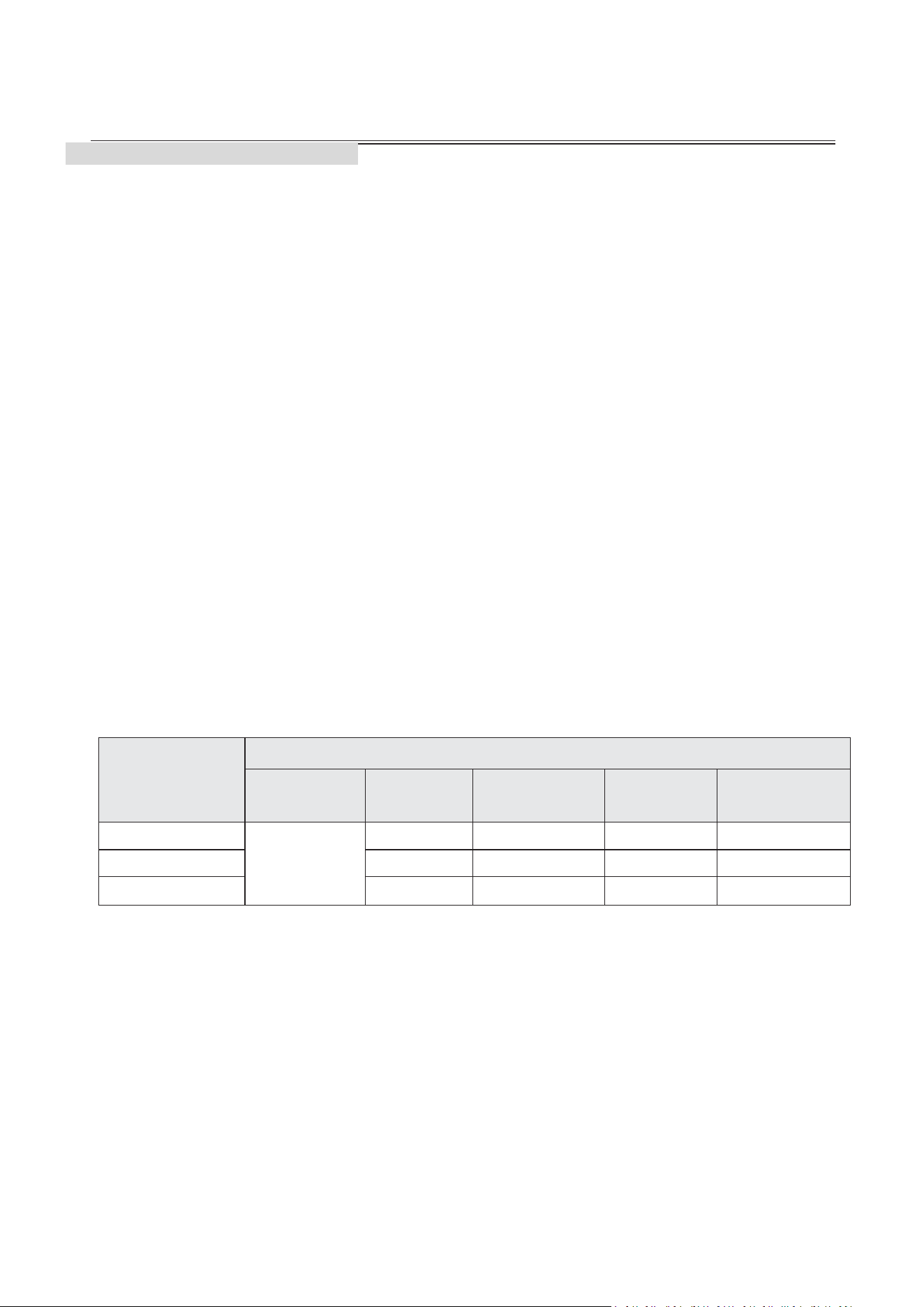
Ensure power cables and wire diameters meet the following specifications:
Model
Specification
Power
Supply
Max
Current
MCA
MOP
(Breaker)
Wire Gauge
(Copper)
Flow Pro 58
208V-240V/60
Hz
16.2A
22A
30A
12 AWG
Flow Max 80
22.9A
32A
45A
10 AWG
Flow Max 107
30A
41A
50A
8 AWG
[ ] Protection:A dedicated HACR-rated (Heating, Air Conditioning, and
Refrigeration) circuit breaker and a certified GFCI (Ground Fault Circuit Interrupter)
are prepared according to local standards.
3. Required Materials (Not Included)
Please note that the following items are required for installation but are not included in the
package:
[ ] Hydraulic Kit: A bypass kit and PVC tubing, along with necessary accessories such
as PVC adhesive, wire strippers,and sandpaper.
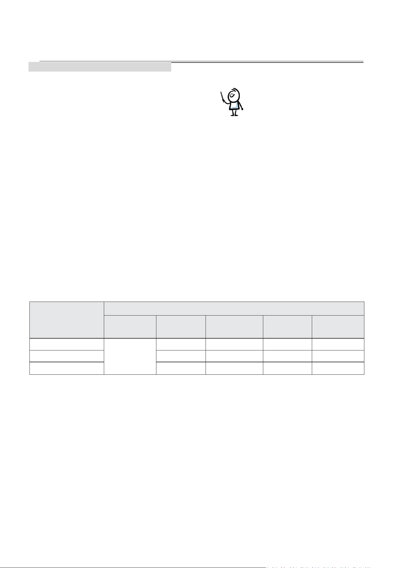
[ ] Mounting Hardware: Suitable expansion bolts or anchor screws are ready to secure
the unit firmly to the foundation.
[ ] Elevation & Drainage: Sturdy fasteners and mounting pads to elevate the unit,
allowing adequate space for condensation drainage.
INSTALLATION
support@blueplenum.com | www.blueplenum.com | BluePlenum All Rights Reserved
15
NOTE: Condensation is not a leak. As the evaporator cools the air, moisture
will naturally form on the fins and drain from the unit. In humid conditions, this
may result in a significant volume of water runoff. This is typical for all
high-efficiency heat pumps.
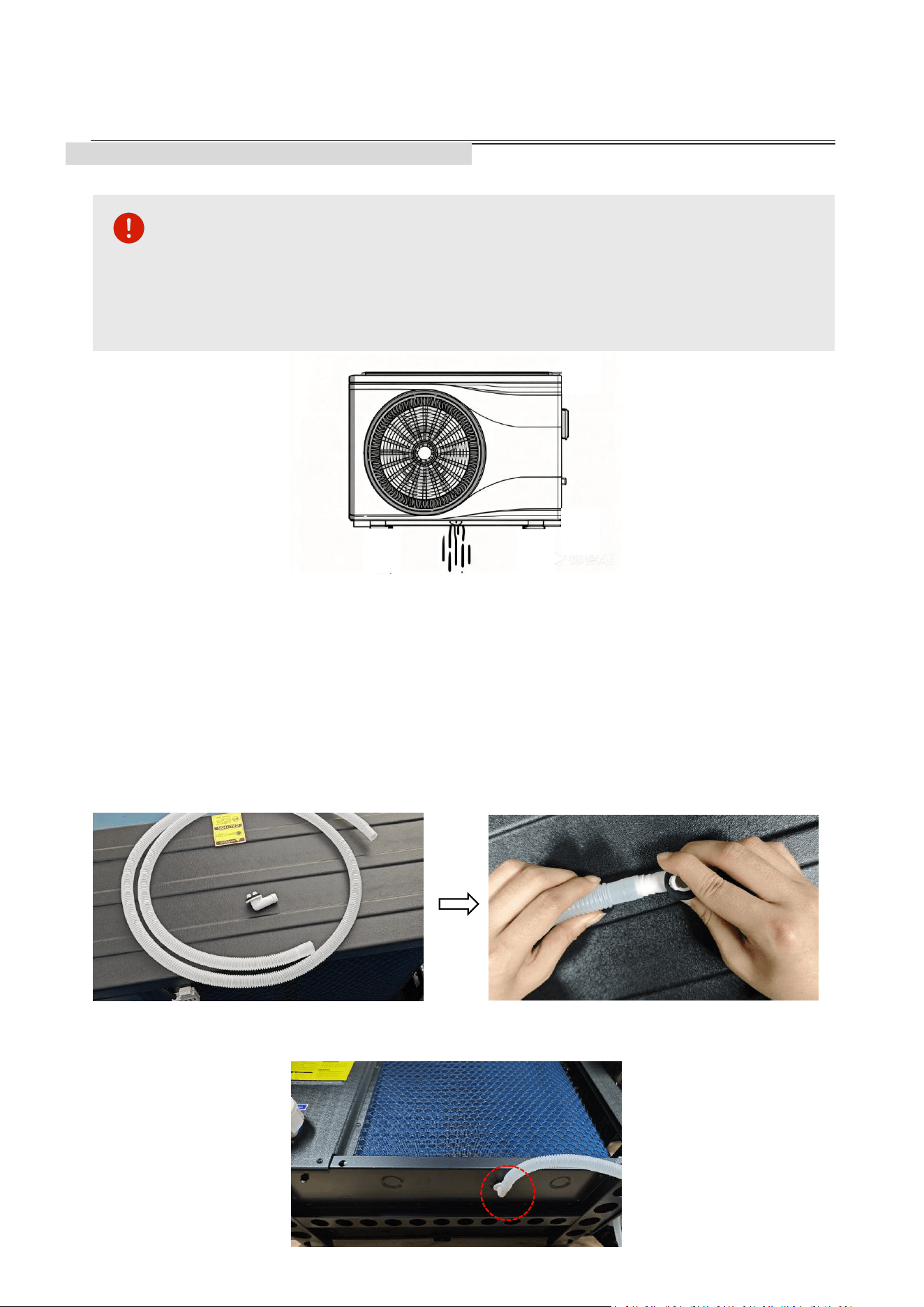
3.4 CONDENSATE DRAINAGE INSTALLATION
In heating mode, the unit will produce condensate. Ensure proper drainage by installing
discharge pipes to direct water to a designated drainage point. Raise the installed heat
pump at least 4 inches off the ground using durable, water—resistant supports.
1. Assemble the condensate pipe(⑥) and condensate pipe connector(⑦).
Note: The condensation drain pipe has different diameters at each end. Please insert the
connector into the narrower end.
2. Connect the condensate pipe to the bottom drain hole.
INSTALLATION
support@blueplenum.com | www.blueplenum.com | BluePlenum All Rights Reserved
16
3.5 PLUMBING INSTALLATION
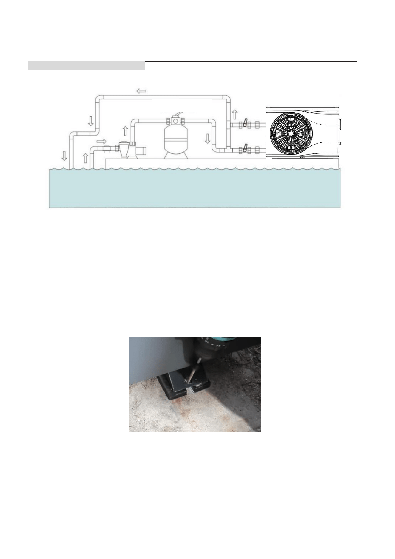
Note: This diagram is for illustrative purposes only. Actual installation may vary
depending on local codes and specific site requirements.
1. Foundation & Mounting
Place insulation mats between the support feet and the foundation during installation.
This helps to dampen noise and vibration while slightly elevating the unit.
The heat pump must be secured to a solid concrete foundation using masonry bolts
prior to the plumbing installation(see figure below). This ensures stability and prevents
excessive vibration or movement during operation.
2. Hydraulic System
Plumbing Configurations
Standard Installations (Small Pools): For systems with 3/4 HP pumps or smaller
using 1-1/2" PVC or flexible hoses, a bypass is generally not required. Connect the
water line IN at the bottom and OUT at the top.
High-Flow Systems (Large Pools): For systems with 1.5 HP pumps or larger and
2-inch plumbing, a bypass system must be installed to regulate flow and protect
Pool Heat Pump
Sand Filter
Water Pump
Pump
Strainer
INSTALLATION
support@blueplenum.com | www.blueplenum.com | BluePlenum All Rights Reserved
17
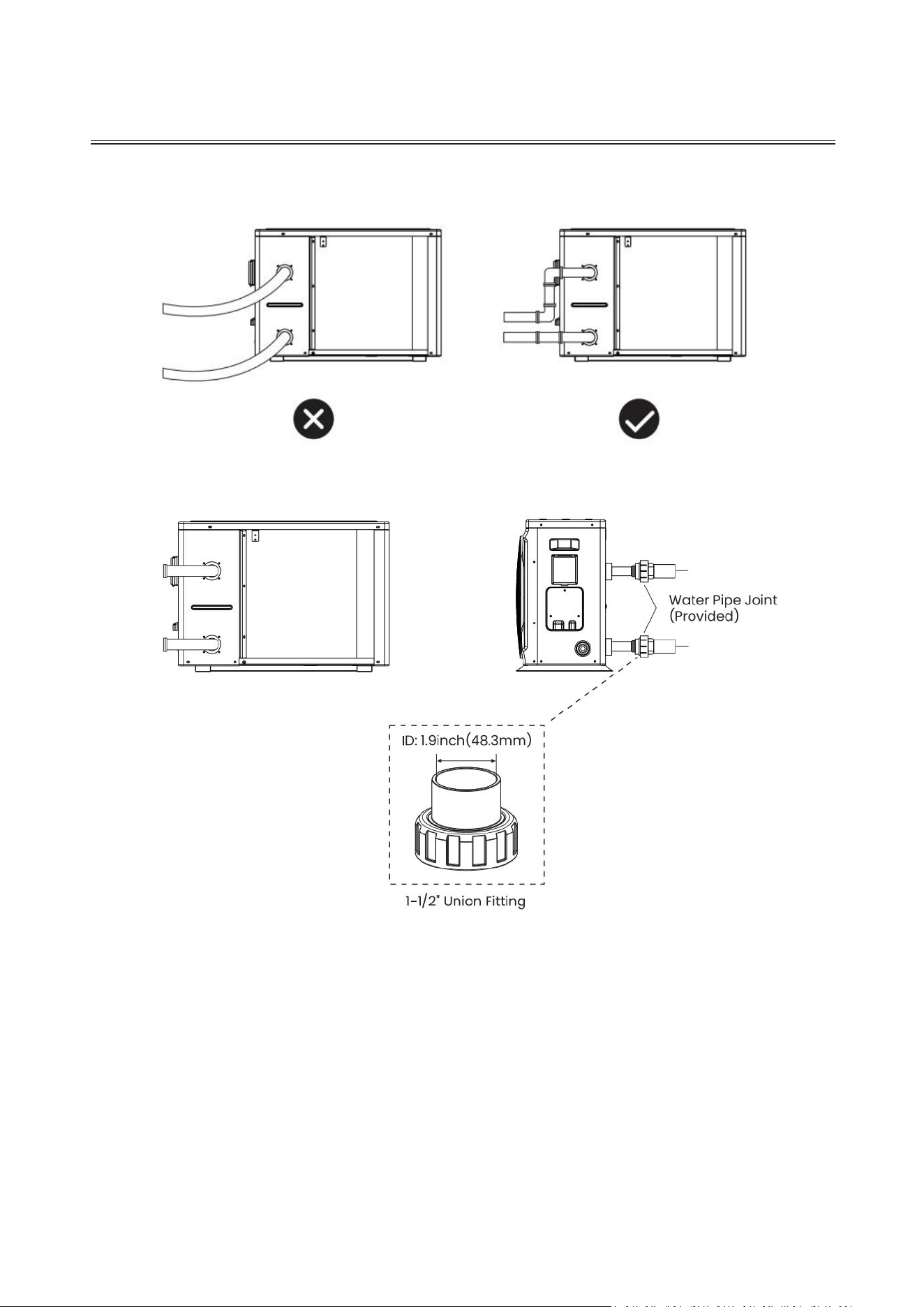
the heat pump. Only connect the water inlets and outlets using rigid PVC pipes as
flexible pipes may not support the water pressure.
Selection of Pipe Diameter:
To maximize heating efficiency, the heat pump should be installed as close to the
pool as safety regulations allow. Keep pipe runs short to minimize heat loss; the
total distance should not exceed 30 feet.
Outlet
Inlet
INSTALLATION
support@blueplenum.com | www.blueplenum.com | BluePlenum All Rights Reserved
18
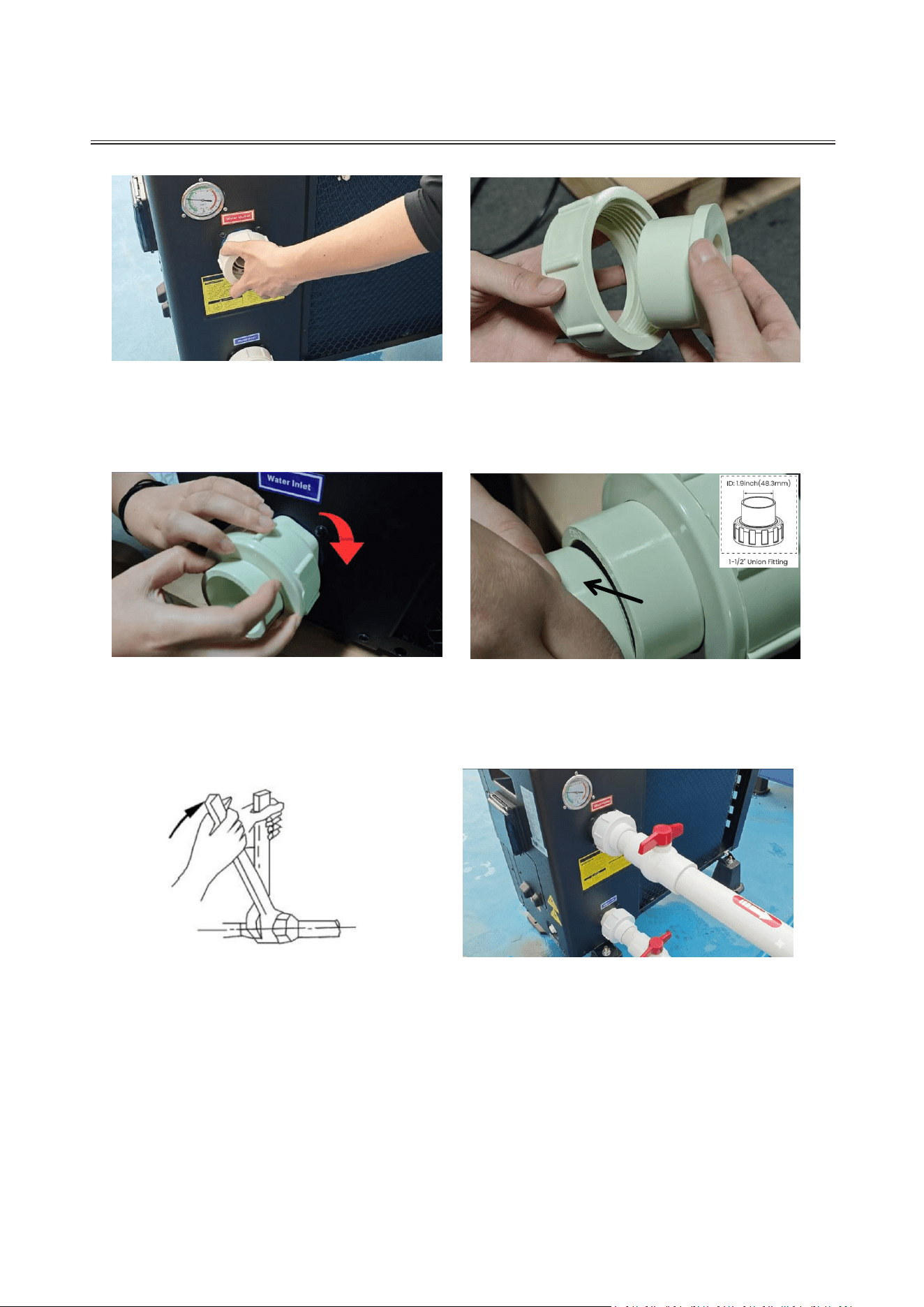
Plumbing Instructions
1. Unscrew and remove the caps from the
Inlet and Outlet water connectors.
2. Take the 1.9" (internal diameter) pipe
adapters from the accessories box and
place them into the connector caps.
3. Screw the assembly back onto the Inlet
and Outlet ports.
4. Apply a layer of PVC adhesive to the
exterior of your PVC pipe, then firmly
insert it into the water union.
5. Secure the connections using a
double-wrench technique: one to stabilize the
port and the other to tighten. Do not allow the
heat pump's internal pipes to rotate during
installation.
Apply PVC
Adhesive
6. Completion: Apply the same installation
method to both inlet and outlet connections.
INSTALLATION
support@blueplenum.com | www.blueplenum.com | BluePlenum All Rights Reserved
19
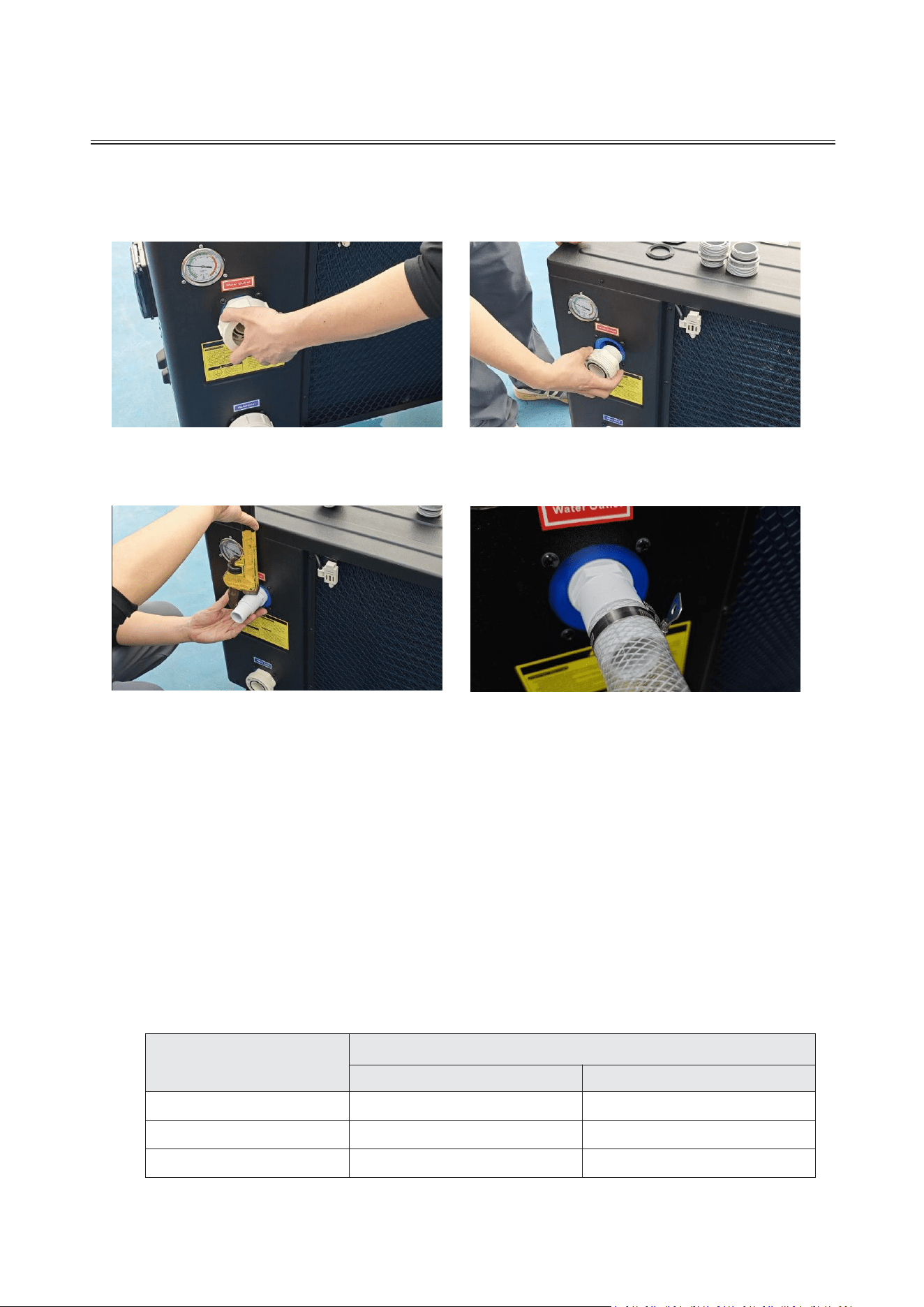
Connector Replacement (Optional)
If your pipe dimensions do not match the unit's connectors, we offer the following
conversion solutions:
Extended Reading: The choice of water pump and filters setup can affect your heat
pump's overall performance and heating efficiency.
Water Pump: A separate water pump is required to circulate water through the heat
pump.
Selection of water pump: Water Flow Volume of water pump=1.2 * heat pump
Water Flow Volume.
Model
Rated Water Flow
Heat Pump
Water Pump
Flow Pro 58
32GPM
39GPM
Flow Max 80
44GPM
53GPM
Flow Max 107
59GPM
71GPM
Filters:
3. Thread and tighten the 1.25"&1.5" hose
adapter(②) or 1.5" hose adapter(③)using a
wrench. (Note: Apply pipe glue or Teflon
tape to the threaded connections to
ensure a leak-proof seal if a rubber gasket
is not provided.)
2. Rotate and remove the PVC pipe
connectors from the inlet and outlet ports.
1. Unscrew and remove the caps from the
Inlet and Outlet water connectors.
4. Insert the hose onto the connector, slide
the hose clamp over it, and tighten the
handle to secure the hose in place.
INSTALLATION
support@blueplenum.com | www.blueplenum.com | BluePlenum All Rights Reserved
20
To prevent debris from damaging the system, install a pump strainer (hair/lint
collector) upstream of the water pump. Alternatively, use a pump with an
integrated strainer basket.
A sand filter must be installed downstream of the water pump to remove fine
impurities and ensure clear water flows into the heat pump.
Regularly clean the pool filter to prevent debris buildup and maintain optimal flow.
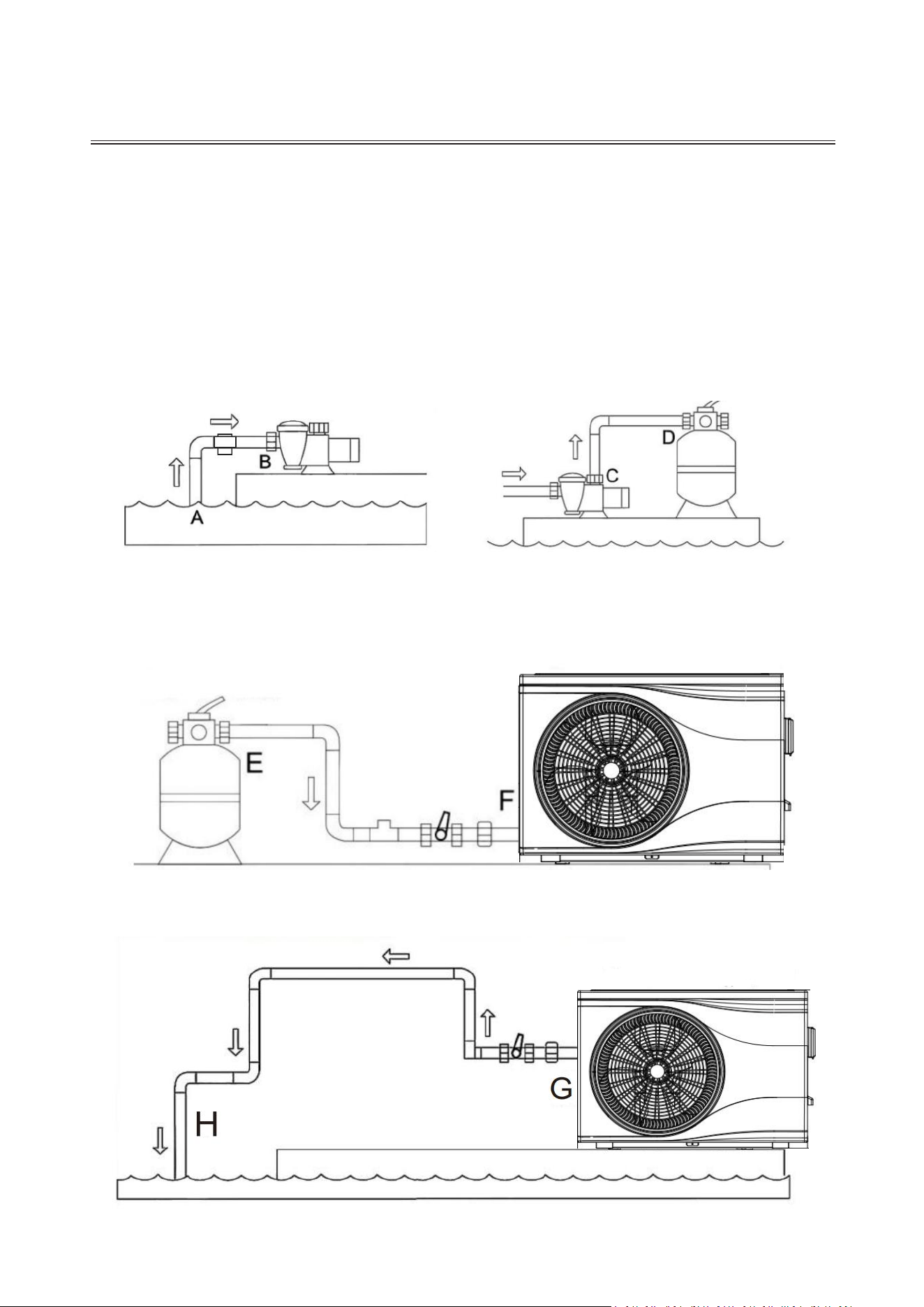
Pool System Installation:
1. Water Inlet Connection: Connect the pool
outlet to the Pump Strainer, then route it to
the Water Pump inlet using dedicated
piping. Ensure the water flow follows the
designated path from A to B.
2. Filtration Connection: Connect the
Water Pump outlet to the Sand Filter inlet.
The water flow direction must follow the
path from C to D.
3. Heat Pump Inlet Connection: Connect the Sand Filter outlet to the Inlet port of the Heat
Pump (typically located at the bottom). The water flow direction must follow the path from E to F.
Pool Heat Pump
Sand Filter
Sand Filter
Water Pump
Water Pump
Pool Heat Pump
4. Return Line Connection: Connect the Outlet port of the Heat Pump (typically located at the
top) back to the pool’s return inlet. The water flow direction follows the path from G to H.
Pump Strainer
INSTALLATION
support@blueplenum.com | www.blueplenum.com | BluePlenum All Rights Reserved
21
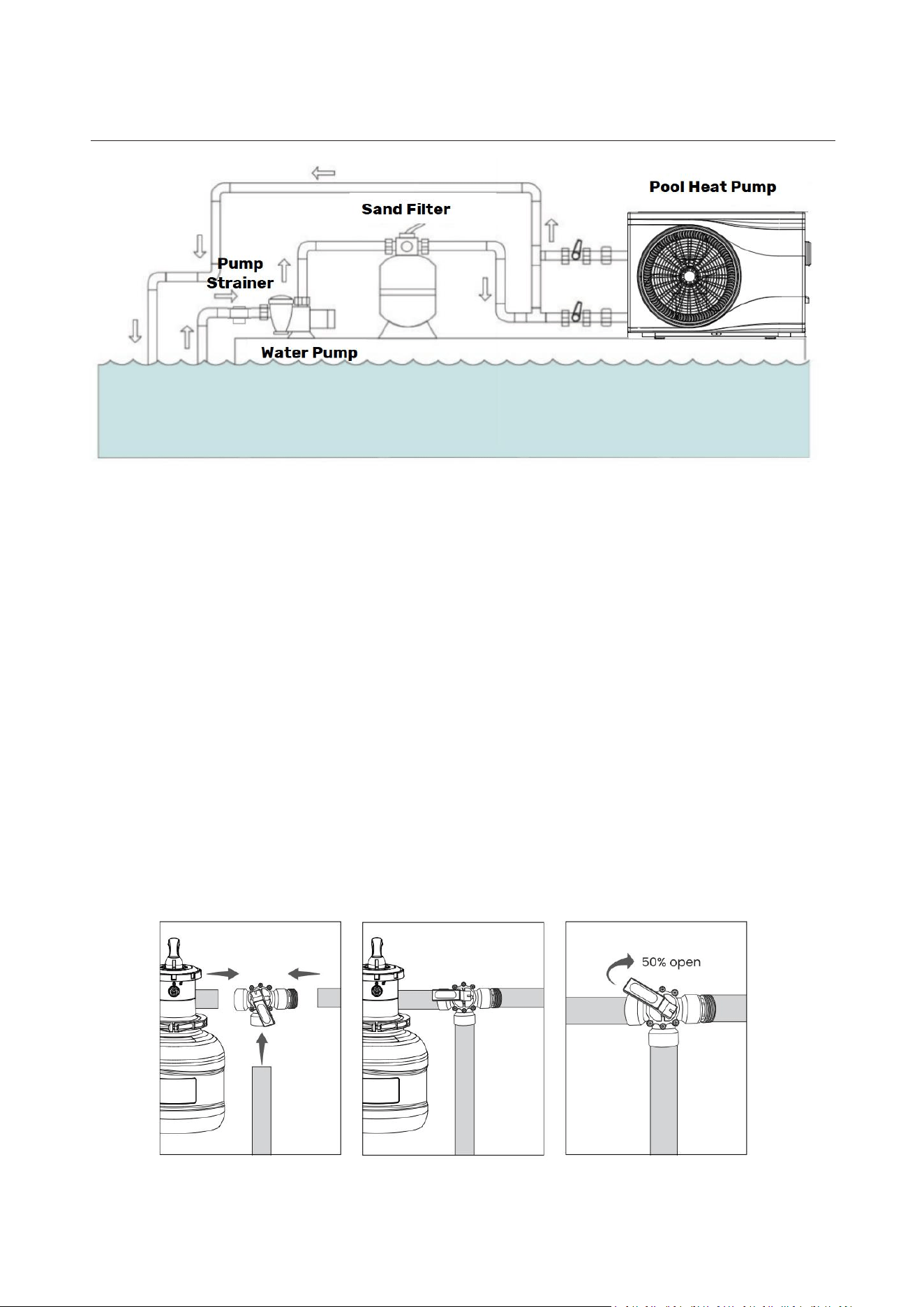
Bypass Valve Adjustment
If a bypass is installed, optimize heating efficiency as follows:
Step 1: Set the bypass valve to 50% open.
Step 2: Gradually adjust the valve to the lowest flow rate that does not trigger
a E03 “Water Flow Protection” error.
Temperature Differential : The difference between Inlet and Outlet water
should be 1–5°F. If the difference exceeds 5°F, increase the water flow through
the heat pump.
Higher water flow does not equate to more heat. BluePlenum heat pumps are engineered
to operate within a specific flow rate range to ensure optimal heat transfer, maximum
efficiency, and long-term system reliability.
5. Completion: Ensure all connections are secured with PVC adhesive and checked for leaks
before operating the system.
INSTALLATION
support@blueplenum.com | www.blueplenum.com | BluePlenum All Rights Reserved
22
3.6 ELECTRICAL INSTALLATION
1. Electrical Setup Requirements:
To ensure safe operation and compliance with the National Electrical Code (NEC) and all
applicable local codes, the unit must be connected by a licensed electrician according to
the following specifications:
GFCI Protection: The main power supply must be protected by a Class A Ground
Fault Circuit Interrupter (GFCI). This is a mandatory safety requirement for all
swimming pool equipment to prevent electrical shock.
Circuit Breaker: Use a dedicated HACR-rated (Heating, Air Conditioning, and
Refrigeration) circuit breaker. This type is designed to handle the high inrush current
during compressor startup without nuisance tripping.
Field Wiring: All field wiring must be copper and sized according to the unit's
Minimum Circuit Ampacity (MCA). Use outdoor-rated, sunlight-resistant conduit and
wire as required by local codes.
Power Supply: Voltage, frequency, and capacity must match the unit's nameplate.
Ensure power cables and wire diameters meet the following specifications:
Model
Specification
Power
Supply
Max
Current
MCA
MOP
(Breaker)
Wire Gauge
(Copper)
Flow Pro 58
208V-240V/60
Hz
16.2A
22A
30A
12 AWG
Flow Max 80
22.9A
32A
45A
10 AWG
Flow Max 107
30A
41A
50A
8 AWG
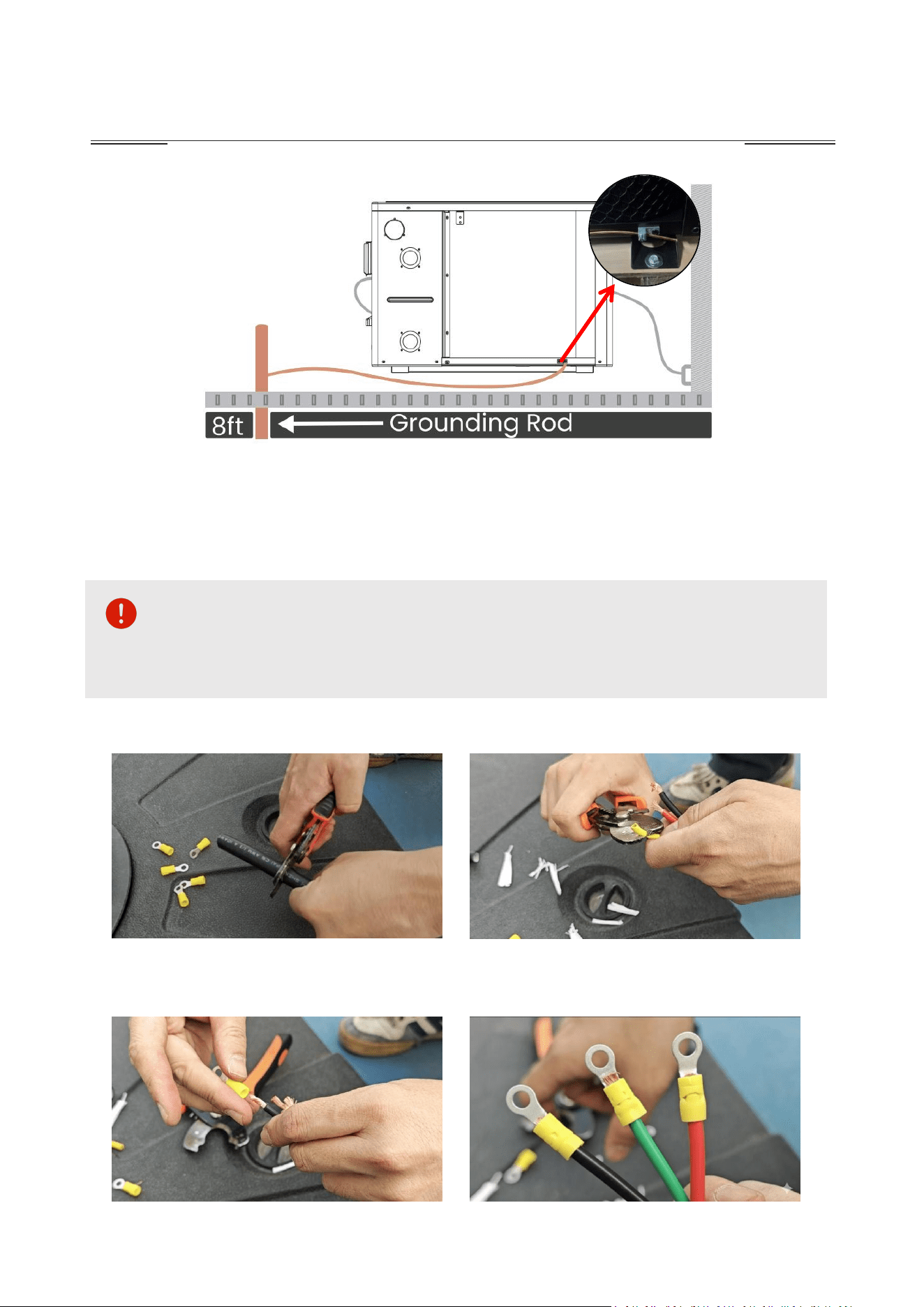
Bonding: The unit must be properly bonded to the pool's bonding grid using a solid
copper wire (minimum 8 AWG) connected to the bonding lug on the chassis.
INSTALLATION
support@blueplenum.com | www.blueplenum.com | BluePlenum All Rights Reserved
23
Emergency Disconnect: For public installations, an emergency shut-off switch must
be installed within sight of the heat pump, per NEC 680 requirements.
WARNING: DISCONNECT and LOCK OUT all power sources to the heat
pump before attempting any installation, service, or maintenance. Failure to do so
can result in severe personal injury or death.
2. Electrical Connection
1. Remove the outer cable jacket of your
cable to expose the inner conductors. Be
careful not to nick the inner wire insulation.
2. Strip insulation from each wire end.
3. Slide ring terminals onto the bare copper
strands. Use a crimping tool to secure the
terminal to the wire.
4. Pull gently to ensure a tight connection
with no exposed copper.
INSTALLATION
support@blueplenum.com | www.blueplenum.com | BluePlenum All Rights Reserved
24
3.7 POST-INSTALLATION TESTING
1. Safety and Operational Checks
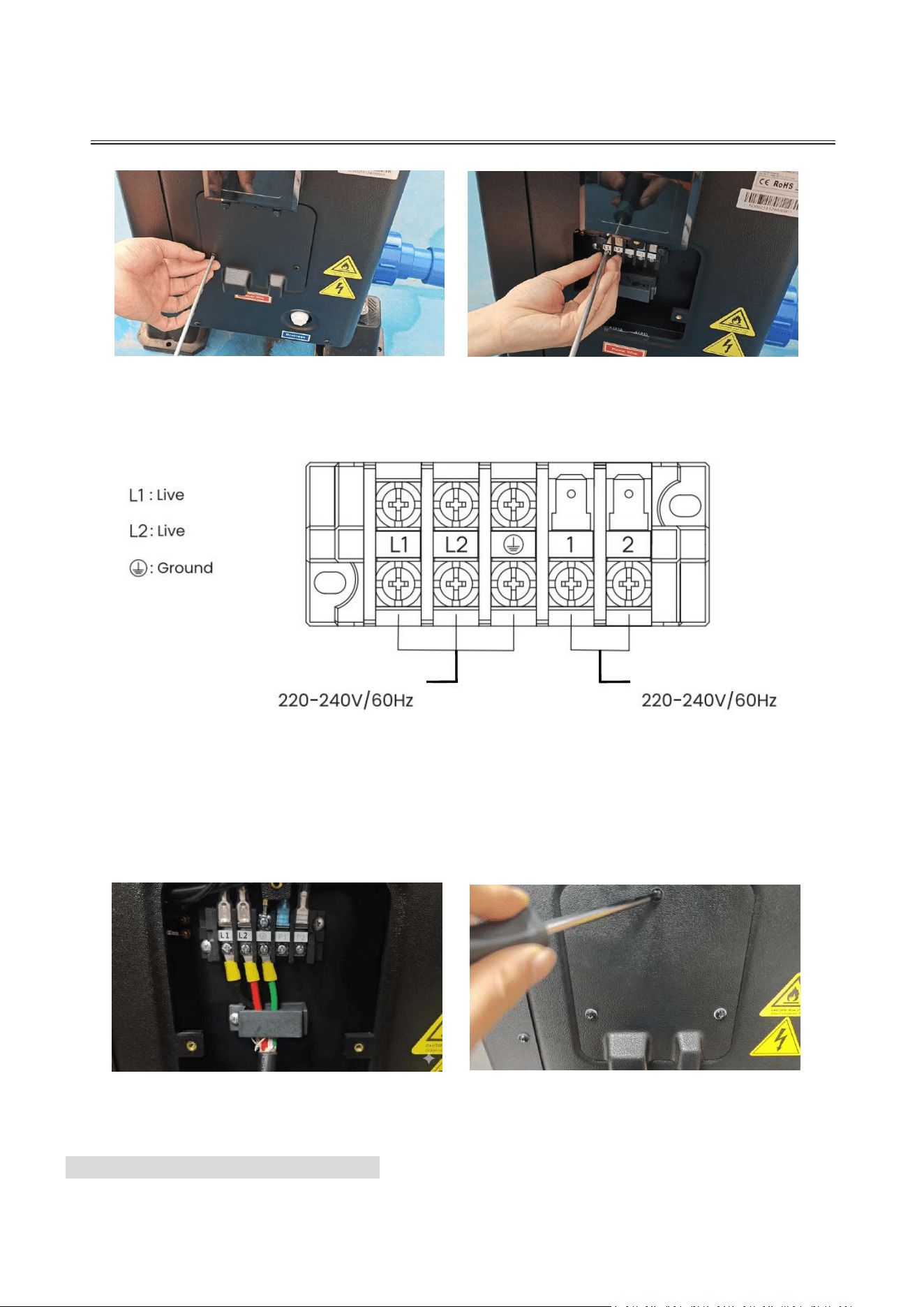
5. Remove the electrical access panel on
the side of the unit with a screwdriver to
access the terminal block.
GREEN
RED
6. Loosen the screws on terminals to
prepare for wire insertion.
BLACK
7. Connect the power supply cable to the terminal block according to the diagram above. The
water pump can be connected to P1, P2 and ground terminals based on actual
requirements(only support 208-240V water pumps).
Both the water pump and the heat pump share the same grounding terminal. When the water
pump is connected to the heat pump, starting the unit will activate the water pump first. The
heat pump will only begin operation once water circulation is detected.
Pool Heat Pump
Water Pump
8. Position the cable under the strain relief
clamp and tighten the screws to prevent
wire movement.
9. Reinstall the electrical access panel and
tighten all screws.

INSTALLATION
support@blueplenum.com | www.blueplenum.com | BluePlenum All Rights Reserved
25
Live Components: Confirm no live electrical components are exposed during startup,
maintenance, or drainage.
Grounding: Verify the integrity of the equipment grounding system.
2. Pre-Operational Inspection
Installation: Confirm the unit is installed on a level, stable surface per instructions.
Power Supply: Verify the supply voltage matches the unit's nameplate rating
208V-240V/1PH/60Hz.
Connections: Inspect all plumbing and electrical connections for tightness and
proper fit.
Airflow: Ensure air intake and exhaust ports are completely unobstructed.
Drainage: Confirm the condensate drainage system is clear and leak-free.
Protection: Verify the leakage protector (GFCI) are functional.
Ground Wire: Ensure the ground wire is securely bonded to the grounding terminal.
3. Startup and Trial Procedure
Preparation: Conduct a final inspection of all wiring and plumbing. Ensure the pool
system is filled with water before applying power. Never operate the unit without
water flow.
System Priming & Air Purge: Before using the unit for the first time, follow the
instructions below based on your installation type:
Option A: If the water pump is wired directly to the heat pump terminals.
Power on the controller, navigate to the Function Menu, and select "User
Functions." Choose "
Water Circuit Emptying
" to bleed air from the system before
starting the heat pump(For more detailed instructions, please refer to the "CONTROL
PANEL OPERATION" section). Once activated, the water pump will run first to prime
the system. This function will automatically turn off once the heat pump begins
operation.
Option B: If the water pump and heat pump have separate power supplies.
First, turn on the water pump and let it run for 20 minutes to ensure all trapped air is
purged from the plumbing. Once the water flow is steady and the air is fully removed,
you may then power on the heat pump.
Power On: press the ON/OFF button on the control panel to run the unit at the set

INSTALLATION
support@blueplenum.com | www.blueplenum.com | BluePlenum All Rights Reserved
26
temperature.
Performance Monitoring: During the initial run, monitor the following:
Control Panel: Verify the touch screen is highly responsive and the display
functions correctly.
Leakage: Inspect the entire heating circulation system for leaks.
Condensate: Verify that condensate water is draining properly.
Vibration: Listen for any unusual noises or excessive vibrations.
4. End Trial Procedure
Power Off: Press the ON/OFF button on the control panel or Tuya Smart APP to turn
off the unit.
Capacitor Discharge: Turn off the main breaker and wait at least 5 minutes. Ensure
all capacitors are fully discharged to avoid electrical shock or sparking.
CONTROL PANEL OPERATION
support@blueplenum.com | www.blueplenum.com | BluePlenum All Rights Reserved
27
Note: BluePlenum pool heat pump features a side-mounted 4-inch TFT
color control panel, providing an intuitive, smartphone-like interface. Always
close the waterproof cover after use to prevent water damage and ensure
long-lasting performance.
4. CONTROL PANEL OPERATION
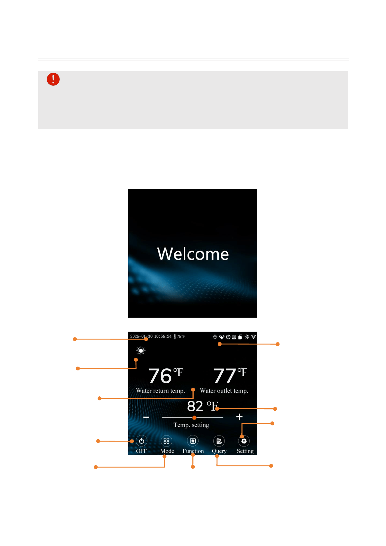
4.1 Welcome Page
The "Welcome" page appears for three seconds during startup, then will enter the
homepage. The screen turns off after two minutes of inactivity; simply touch the screen to
wake it.
4.2 Homepage
Status Bar 1
Current Date &Time
Ambient Temperature
Status Bar 3
Operation Mode
Status Bar 2
Device Status
(Compressor/Fan/Water
Pump)
Wi-Fi Connectivity
Inlet/Outlet Temperature
Real-time Inlet/Outlet Water
Temp.
Target Temperature
Set Target Water Temp.
ON/OFF Button
Mode Button
Select Operation Mode
Setting Button
System & Display Settings
Function Button
User Settings
Wi-Fi Configuration
Query Button
Running Status Inquiry
Fault Logs
CONTROL PANEL OPERATION
support@blueplenum.com | www.blueplenum.com | BluePlenum All Rights Reserved
28
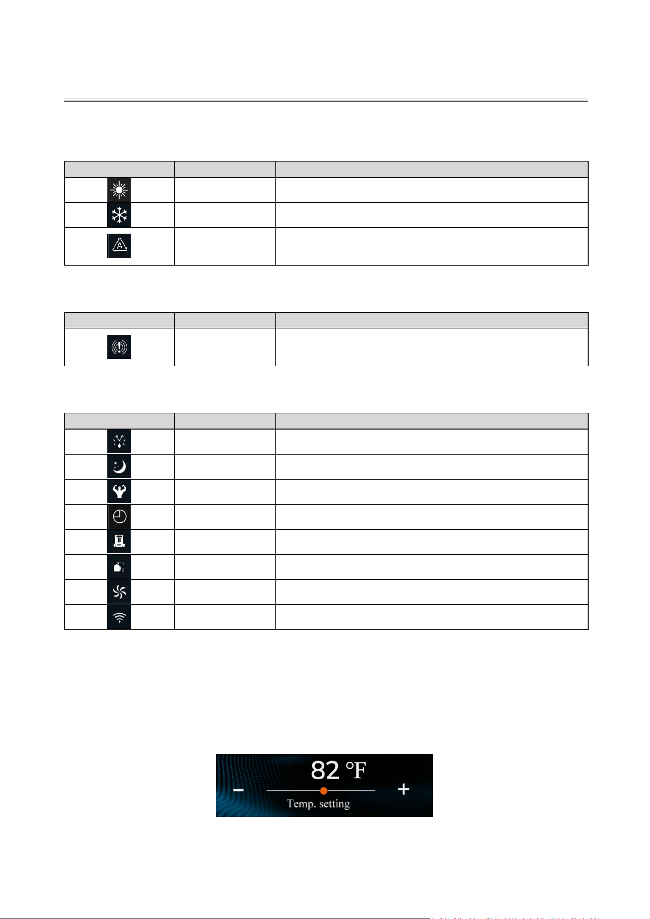
4.3 Icon Legend
Mode Icons
ICON
FUNCTION
DESCRIPTION
Heating Mode
Unit is in heating mode.
Cooling Mode
Unit is in cooling mode.
Auto Mode
Unit automatically switches between heating
and cooling to maintain the set temperature.
Alerts
ICON
FUNCTION
DESCRIPTION
Error
Flashes to indicate a system error. Tap for
details.
Operation Status
ICON
FUNCTION
DESCRIPTION
Defrosting
Unit is in defrost mode.
Quiet Mode
Unit is operating at a reduced noise level.
Boost Mode
Unit is operating at high-performance level.
Timer
Indicates the timer function is active.
Water Pump
Indicates the water pump is running.
Compressor
Indicates the compressor is running.
Fan
Indicates the fan is running.
Wi-Fi Status
Indicates a successful Wi-Fi connection.
4.4 Temperature Setting
Manual Adjustment: Use the "+" and "-" buttons on the homepage to set your desired
temperature for the selected mode.
Slider Control: For quicker adjustments, drag the temperature slider to fine-tune the
setting for the current mode.
4.5 Power On/Off
CONTROL PANEL OPERATION
support@blueplenum.com | www.blueplenum.com | BluePlenum All Rights Reserved
29
Operation: Press the ON/OFF button " " to turn the controller on or off.
Status Indicator: The display will show "ON" when the unit is active and "OFF" when it
is in standby.
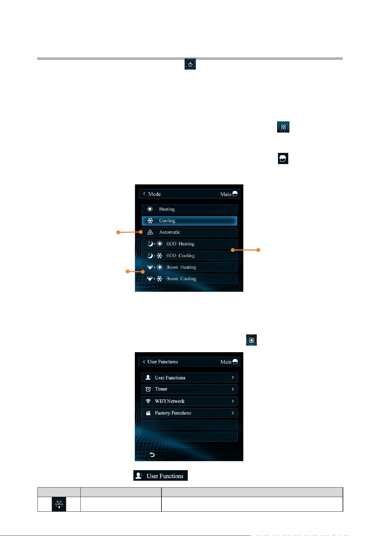
4.6 Mode Menu
Select Modes: While the screen is active, press the Mode button " " on homepage
to open the mode selection screen.
Back to Homepage (Available on all screens): Tap the Main icon " " in the
upper-right corner to return to the homepage.
4.7 Function Menu
Access the system settings by tapping the Function button " " on the homepage.
User Functions: Select " " to manage specific maintenance tasks
ICON
FUNCTION
DESCRIPTION
Forced Defrosting
Manually initiate defrosting. (Note: The system also
Auto Mode
(Constant Temperature Mode)
Automatically switches
between heating and cooling to
maintain the set temperature.
ECO Heating/Cooling Mode
A low-power, quiet operation
mode designed to maintain
water temperature once the set
temperature is nearly reached.
Boost Heating/Cooling Mode
Operates at maximum power
for fast heating or cooling.
Ideal for initial startup or when
the water temperature needs a
significant adjustment.
CONTROL PANEL OPERATION
support@blueplenum.com | www.blueplenum.com | BluePlenum All Rights Reserved
30
Note: Automatic On/Off schedules can be set on both the control panel and the
mobile app. Please be aware that these two schedules do not synchronize; however, the
heat pump will execute commands from both sources simultaneously.
Example Scenario: If your Control Panel is scheduled for 6:00 PM – 8:00 PM and your App
is scheduled for 5:00 PM – 9:00 PM, the unit will operate as follows:
5:00 PM: The unit receives an "On" command from the App and begins operation.
6:00 PM: The unit receives an "On" command from the Control Panel and remains running.
8:00 PM: The unit receives an "Off" command from the Control Panel and stops working.
9:00 PM: The unit receives an "Off" command from the App and remains off.
The unit runs from 5:00 PM – 8:00 PM. We recommend using the Tuya Smart APP to
manage all timer settings.
defrosts automatically based on environmental
conditions).
Water Circuit
Emptying
Use this function to bleed air from the system before
starting the heat pump. Once activated, the water
pump will run first to prime the system. This function
will automatically turn off once the heat pump
begins operation.
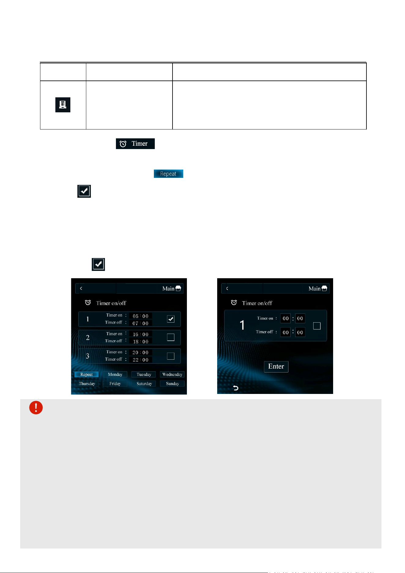
Timer: Access the
" "
from the settings menu to set timer to automate your heat
pump's operation.
Daily Scheduling: Select " " to apply the same schedule every day. Once set, tap
the " " button next to the time slot and the unit will follow this schedule automatically.
Weekly Scheduling:
1) Weekly Customization: Choose any day (Monday–Sunday) to set unique operating times
for each day of the week.
2) Setting the Time: Select your desired time slot and enter the start and end times. Tap
the " " button and press "Enter" to save your schedule.
Timer
Timer
CONTROL PANEL OPERATION
support@blueplenum.com | www.blueplenum.com | BluePlenum All Rights Reserved
31
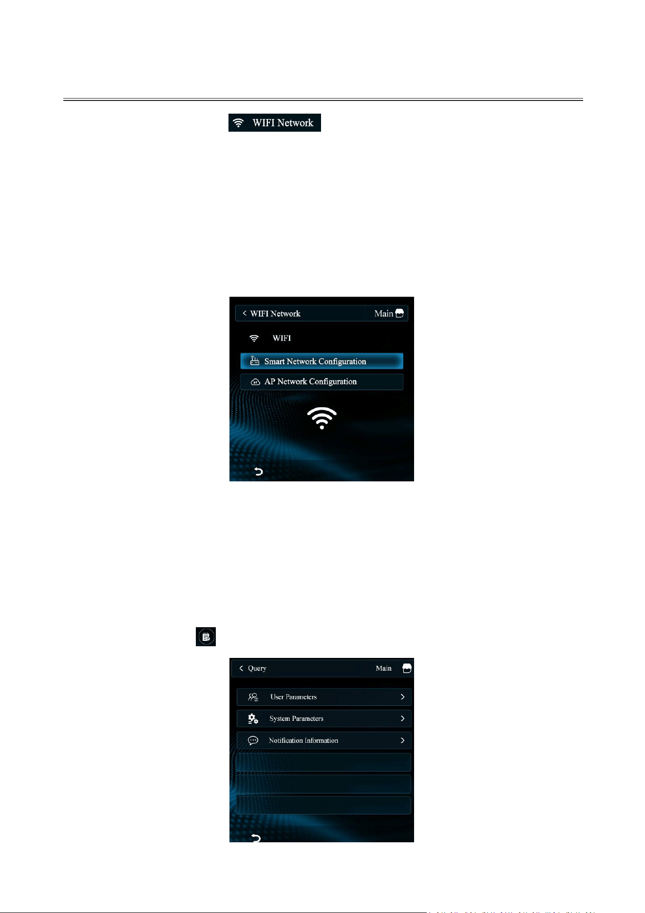
WIFI Network: Access the " " from the settings menu. Connect the unit to
your local Wi-Fi network to enable remote control through the mobile app, allowing you
to manage your heat pump from anywhere.
Smart Network Configuration: Choose this for automatic Wi-Fi setup.
AP Network Configuration: Select this to configure the access point settings
manually.
Note: Both options require a 2.4 GHz Wi-Fi network for a stable connection.
For more detailed remote control instructions, please refer to the "APP CONTROL" section.
Factory Functions: These functions are not intended for daily use; they are reserved
for troubleshooting by our technical support team. Please only access these settings
under the direct guidance of our staff.
4.8 Query Menu
Tap the Query button " " on the Home screen to view system data.
CONTROL PANEL OPERATION
support@blueplenum.com | www.blueplenum.com | BluePlenum All Rights Reserved
32
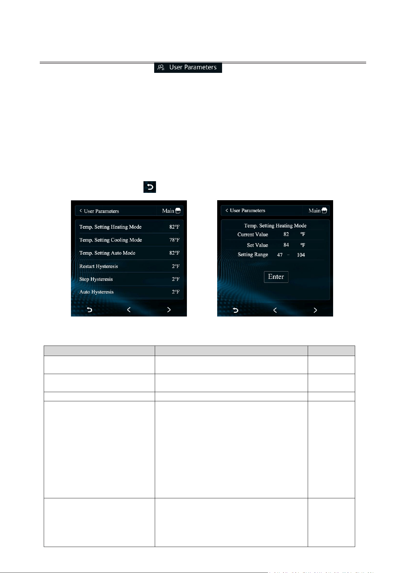
User Parameters: Tap the " " to enter the user settings interface.
Here, you can customize the default temperature for each mode and configure water
pump cycle parameters(optional) to suit your personal preferences.
Adjusting Settings:
1) Select the specific parameter you wish to modify to open the editing screen.
2) Input the new value using the on-screen keyboard.
3) Press "Enter" once to confirm the value, and press "Enter" again to save your
changes.
4) Tap the Back button " " in the bottom-left corner to return to the previous page.
User Parameter Definitions:
Parameter
Definition
Range
Temp. Setting Heating
Mode
Default target temperature in heating mode.
47-104°F
Temp. Setting Cooling
Mode
Default target temperature in cooling mode.
47-83°F
Temp. Setting Auto Mode
Default target temperature in auto mode.
47-104°F
Restart Hysteresis
(Temperature Differential)
This parameter determines the temperature
deviation required for the unit to restart after
reaching its target. It prevents frequent
cycling and protects the compressor:
1) In Heating Mode: If set to 2°F, the unit
will remain on standby until the pool
water cools by 2°F below your target
temperature before turning back on.
2) In Cooling Mode: If set to 2°F, the unit
will restart only after the pool water
temperature rises 2°F above your target
temperature.
2-36°F
Stop Hysteresis
(Over-temperature Offset)
This parameter defines the temperature
"overshoot" allowed before the unit stops,
ensuring the water temperature is fully
stabilized:
1) In Heating Mode: If set to 1°F, the unit
will continue running until the pool water
2-36°F
CONTROL PANEL OPERATION
support@blueplenum.com | www.blueplenum.com | BluePlenum All Rights Reserved
33
reaches 1°F above your target
temperature before shutting down.
2) In Cooling Mode: If set to 1°F, the unit
will continue running until the pool water
reaches 1°F below your target
temperature before shutting down.
Auto Hysteresis
(Mode Switching Buffer)
This setting determines the temperature
threshold for the unit to switch between
heating and cooling when operating in "Auto"
mode:
1) To Start Cooling: If set to 3°F, the unit
will only switch to cooling mode once the
water temperature rises 3°F above your
target setpoint.
2) To Start Heating: If set to 3°F, the unit
will only switch to heating mode once the
water temperature drops 3°F below your
target setpoint.
3) Note: This buffer prevents the system
from "fighting itself" by constantly
switching back and forth between
modes.
2-36°F
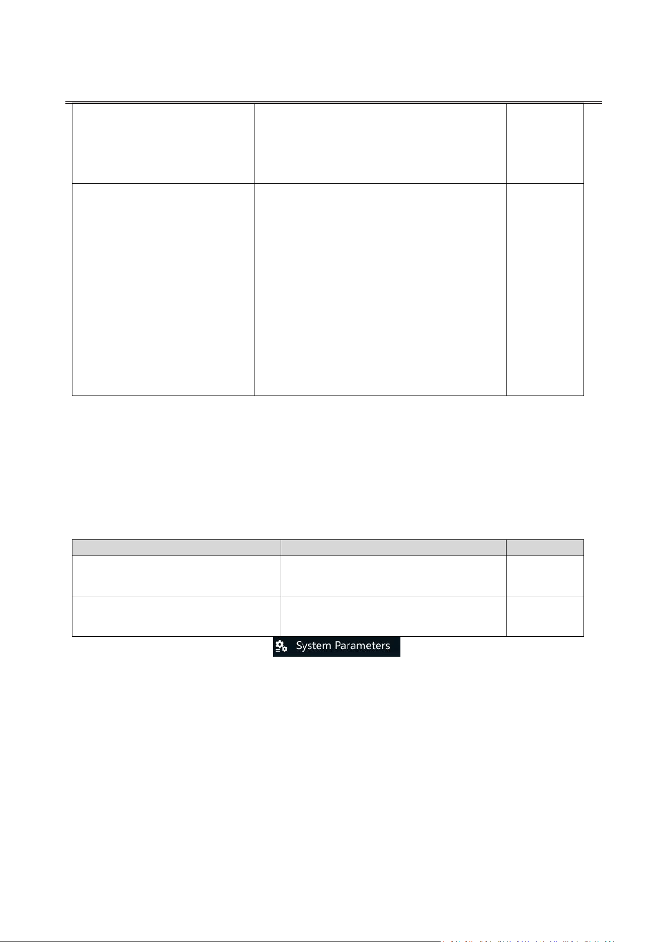
To save electricity, the water pump will pause once the target temperature is reached. The
Constant-Temp Pump Run Cycle determines how often the water pump wakes up to
check the water temperature, while the Constant-Temp Pump Run Time sets how long
the pump runs during each check.
Note: The two parameters only apply when the water pump is wired directly to the heat
pump terminals.
Parameter
Definition
Range
Constant-Temp Pump Run Cycle
(Sampling Interval)
The time interval between automatic
pump starts to check the pool water
temperature.
10-120min
Constant-Temp Pump Run Time
(Sampling Duration)
The duration for which the water pump
operates during each temperature
check.
1-10min
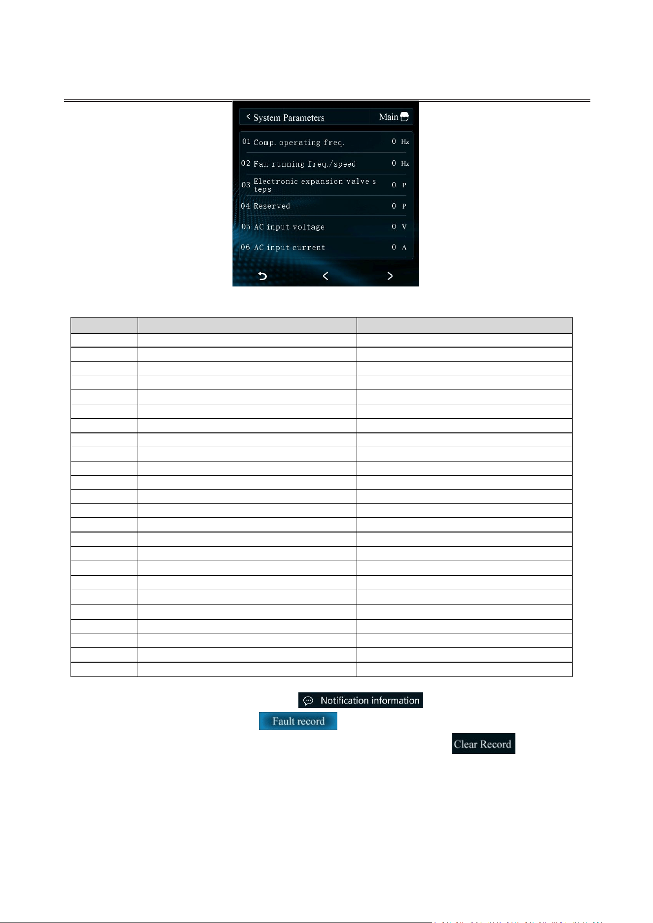
System Parameters: Tap the " " to enter the System
Parameters interface. Here, you can view the real-time operating data and system
parameters for different operation modes. Use the "<" and ">" buttons to navigate
through the pages.
CONTROL PANEL OPERATION
support@blueplenum.com | www.blueplenum.com | BluePlenum All Rights Reserved
34
System Parameters
No
Parameter
Display Range
1
Comp. Operating Freq.
Measured Value
2
Fan running freq./speed
Measured Value
3
Electronic expansion valve step
Measured Value
5
AC Input Voltage
Measured Value
6
AC Input Current
Measured Value
7
Comp. Phase Current
Measured Value
8
Comp. IPM Temp.
Measured Value
11
Ambient Temp.
Measured Value
12
Outer Coil Temp.
Measured Value
13
Inner Coil Temp.
Measured Value
14
Return Air Temp.
Measured Value
15
Exhaust Air Temp.
Measured Value
16
Water Return Temp.
Measured Value
17
Water Outlet Temp.
Measured Value
20
Unit Tooling Number
Measured Value
23
Inverter Driver manufacturer
Measured Value
31
Four-way Valve
Measured Value
33
High Pressure Switch
Measured Value
34
Low Pressure Switch
Measured Value
35
Water Flow Switch
Measured Value
36
Linkage Switch
Measured Value
37
EVU Switch
Measured Value
38
SG Switch
Measured Value
39
SG Status
Measured Value
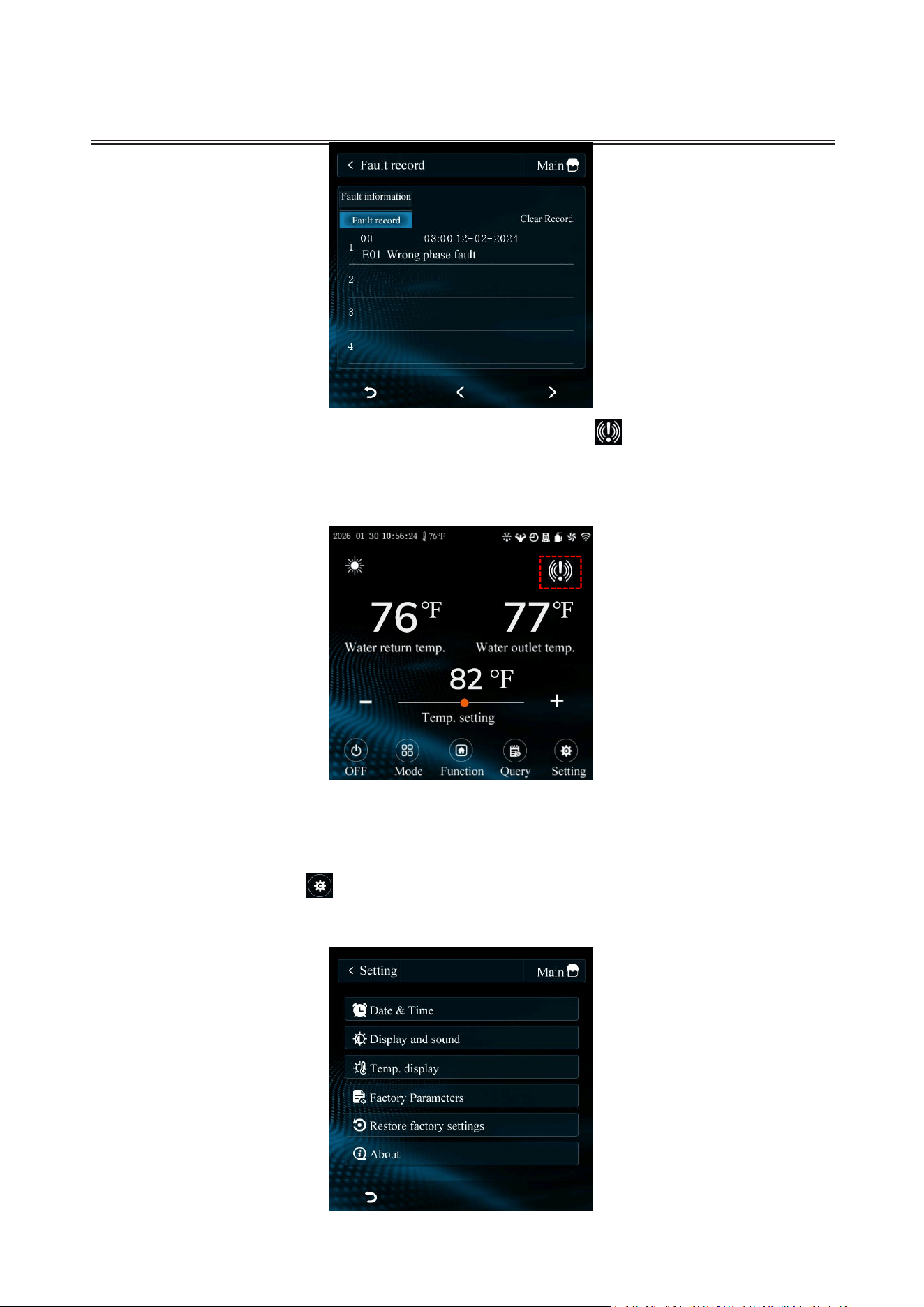
Notification Information: Tap the " " to enter the Fault
Information interface. Select " " to view a detailed history of system
errors and faults. To delete all stored fault records, press the " " button.
CONTROL PANEL OPERATION
support@blueplenum.com | www.blueplenum.com | BluePlenum All Rights Reserved
35
Fault Indicator: When a fault occurs, the error icon " "on the main screen will
flash. You can tap the icon directly to access the Fault Information screen and view
specific error details.
Note: For detailed error codes and troubleshooting, please refer to the "Troubleshooting" section
later in this manual.
4.9 Settings Menu
Tap the Settings button " " on the home screen to to manage your display
preferences.
CONTROL PANEL OPERATION
support@blueplenum.com | www.blueplenum.com | BluePlenum All Rights Reserved
36
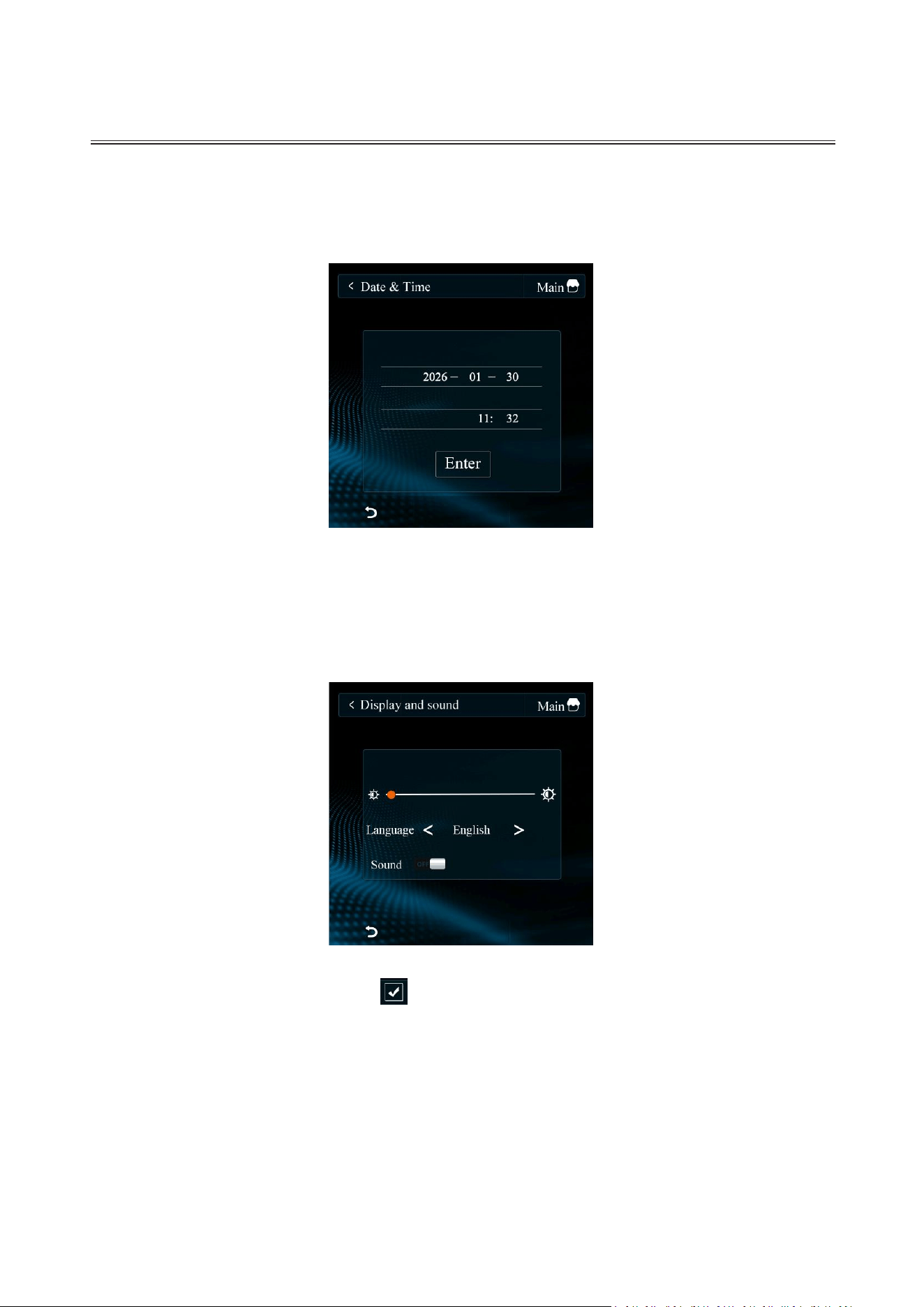
Date & Time : From the Settings menu, select "Date & Time" to adjust the system date
and time. Use the on-screen keyboard to enter the current year, month, and day, then
press "Enter" to save your changes.
Display and Sound: Navigate to "Display and Sound" within the Settings menu. Here,
you can adjust the screen brightness using the slider and toggle the system sound on
or off using the corresponding buttons.
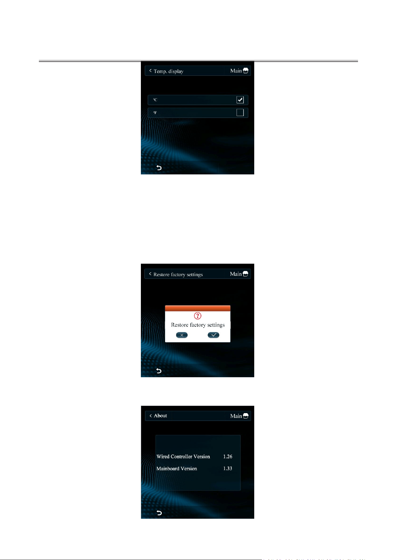
Temperature Display: Tap the “ ” to switch between temperature units (
℃
&
℉
).
CONTROL PANEL OPERATION
support@blueplenum.com | www.blueplenum.com | BluePlenum All Rights Reserved
37
Factory Parameters: These parameters are not intended for daily use; they are
reserved for troubleshooting by our technical support team. Please only check these
parameters under the direct guidance of our staff.
Restore Factory Settings: Follow the prompts to reset the unit to its original factory
defaults.
About: Select "About" to check the control panel and motherboard version
information.
APP CONTROL
support@blueplenum.com | www.blueplenum.com | BluePlenum All Rights Reserved
38
5. APP CONTROL
5.1 PREPARATION BEFORE CONNECTING
1. Ensure your Wi-Fi router supports a 2.4GHz frequency band (5GHz is not supported).
2. Note: Most 5GHz routers can be configured to a 2.4GHz band or a dual-band mode.
3. Verify that your Wi-Fi network name and password are correct.
4. Confirm that your smartphone or tablet is connected to a 2.4GHz network.
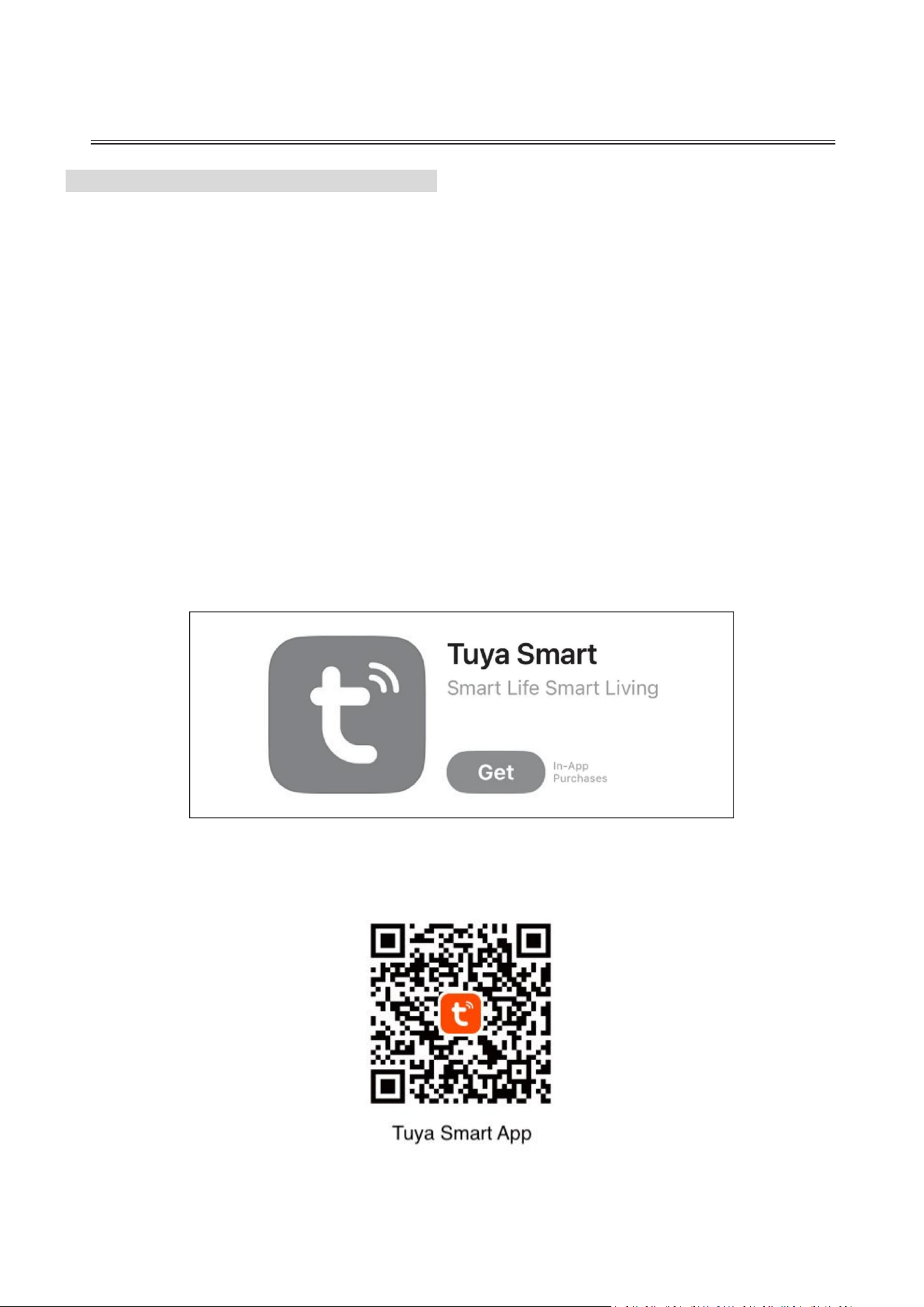
5. Download the "Tuya Smart" app from the App Store (iOS) or Google Play (Android).
Tuya Inc. is the official integrated chip provider and IoT partner for BluePlenum Smart
Inverter pool heat pumps. By leveraging the Tuya Smart App, we provide a seamless
remote connection, allowing you to control and monitor your pool’s temperature from
anywhere in the world.
APP CONTROL
support@blueplenum.com | www.blueplenum.com | BluePlenum All Rights Reserved
39
5.2 LAUNCH THE TUYA SMART APP
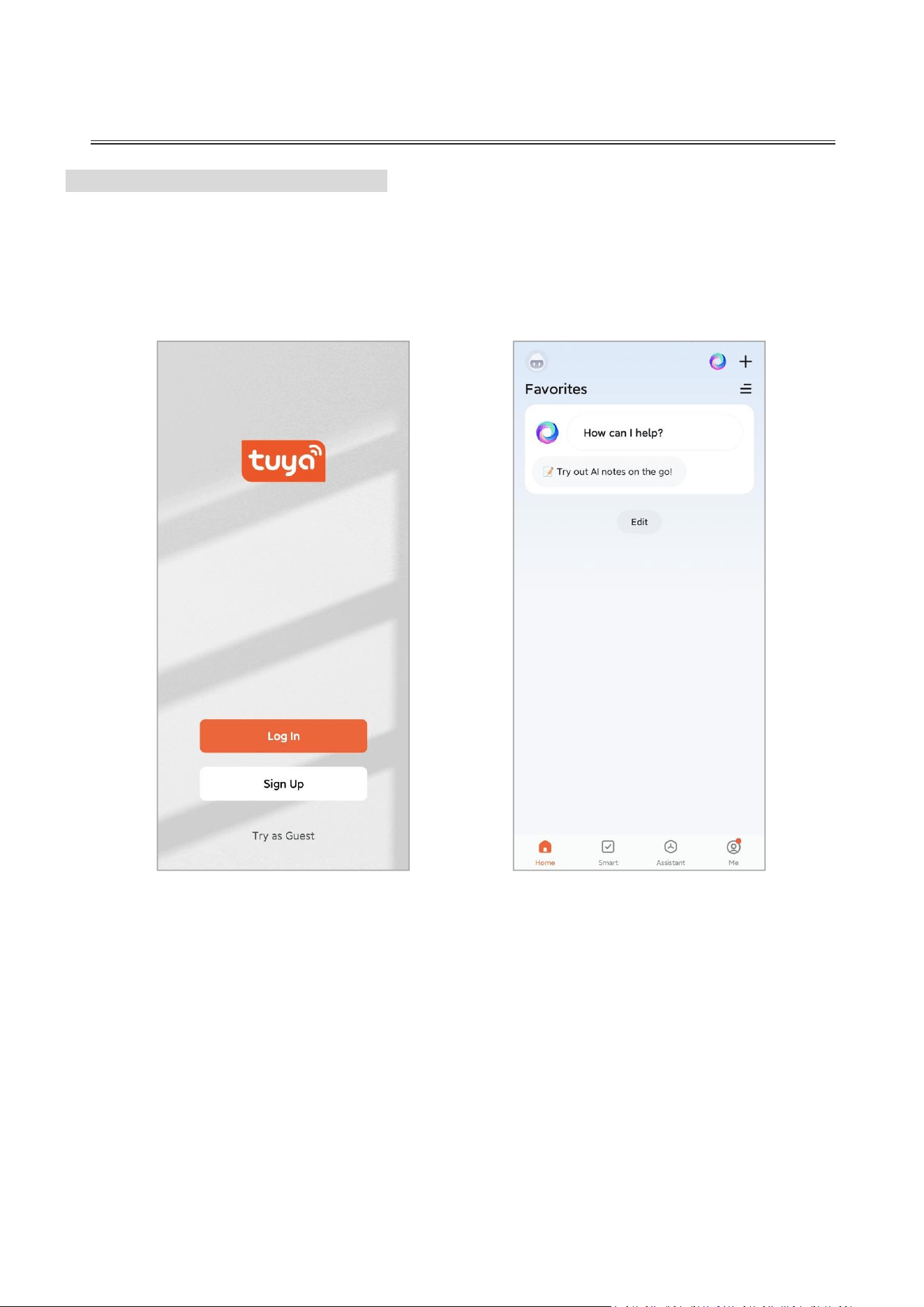
1. Open the Tuya Smart app on your mobile device.
2. Register a new account using your email address or mobile phone number.
3. Log in to your account to proceed with the setup.
Login Screen
Main Dashboard
APP CONTROL
support@blueplenum.com | www.blueplenum.com | BluePlenum All Rights Reserved
40
5.3 PAIRING METHOD
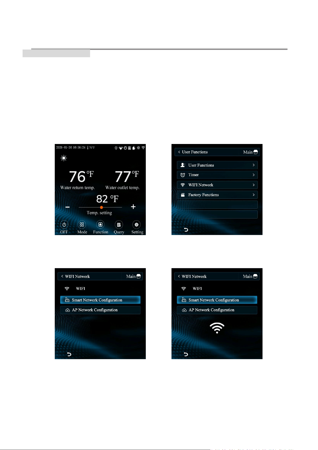
1. Control Panel Preparation
Step 1: On the home screen, tap the "Function" icon to open the operation menu.
Step 2: Select "WIFI Network" from the list of user functions.
Step 3: Tap the "Smart Network Configuration" mode.
Step 4: Confirm that the Wi-Fi icon on the control panel screen is flashing rapidly,
indicating it is ready to pair.
Step 1
Step 2
Step 3
Step 4
APP CONTROL
support@blueplenum.com | www.blueplenum.com | BluePlenum All Rights Reserved
41
Note: We strongly recommend using this Automatic Connection method
for the easiest setup. If the automatic process fails, please refer to the Manual
Connection section or contact customer service for technical support.
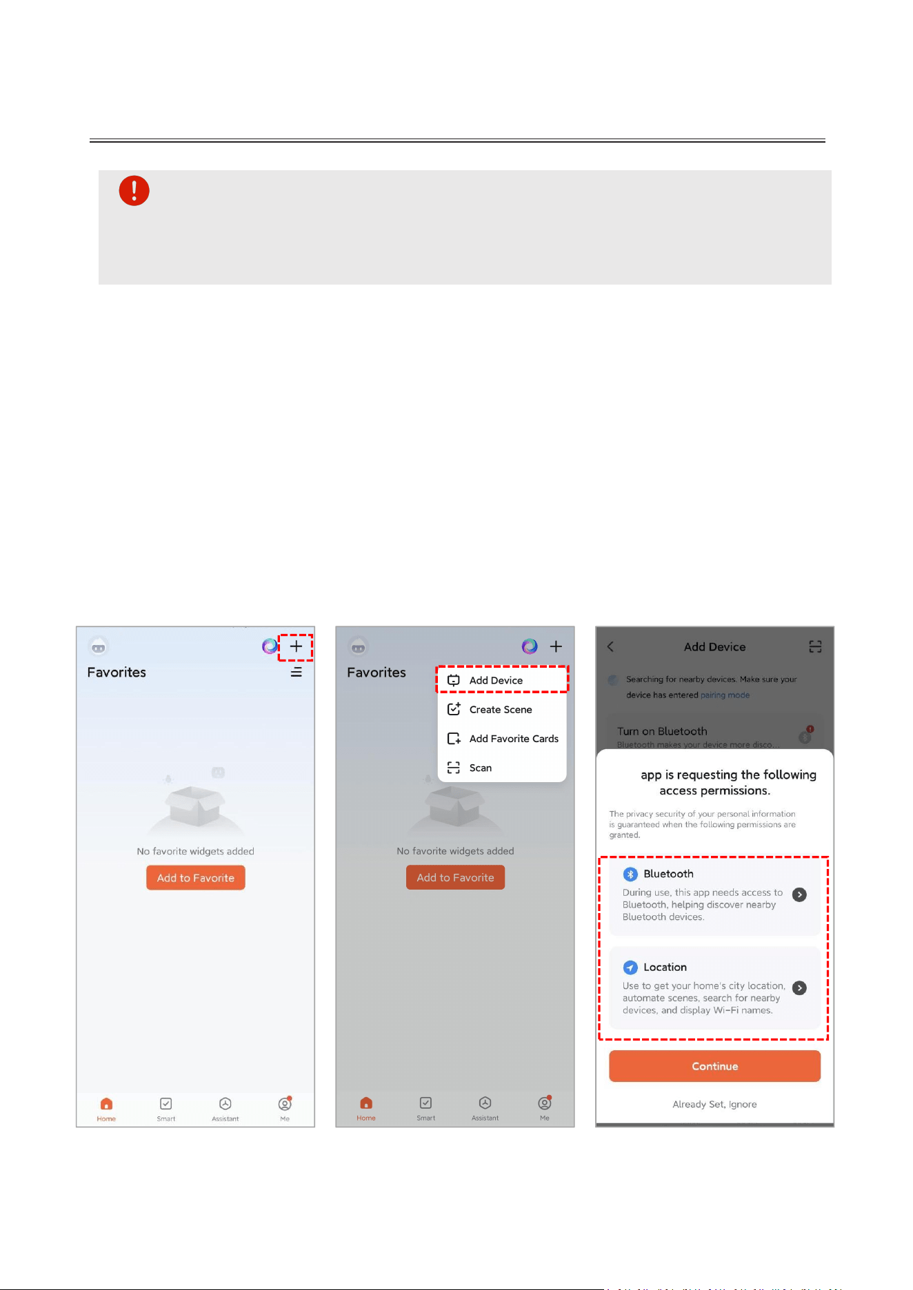
2. Automatic Connection (Recommend)
Open the App: Launch the Tuya Smart app and ensure you are on the Main
Dashboard.
Near the Unit: For a successful pairing, please stand next to the heat pump with your
mobile device.
Add Device: Tap the "+" icon in the top-right corner and select the "Add Device"
button.
Grant Permissions: When prompted, grant the app permission to access Bluetooth
and Location Services. These are required to discover and connect to your heat pump.
Open Tuya Smart
Add Device
Grant Permissions
APP CONTROL
support@blueplenum.com | www.blueplenum.com | BluePlenum All Rights Reserved
42
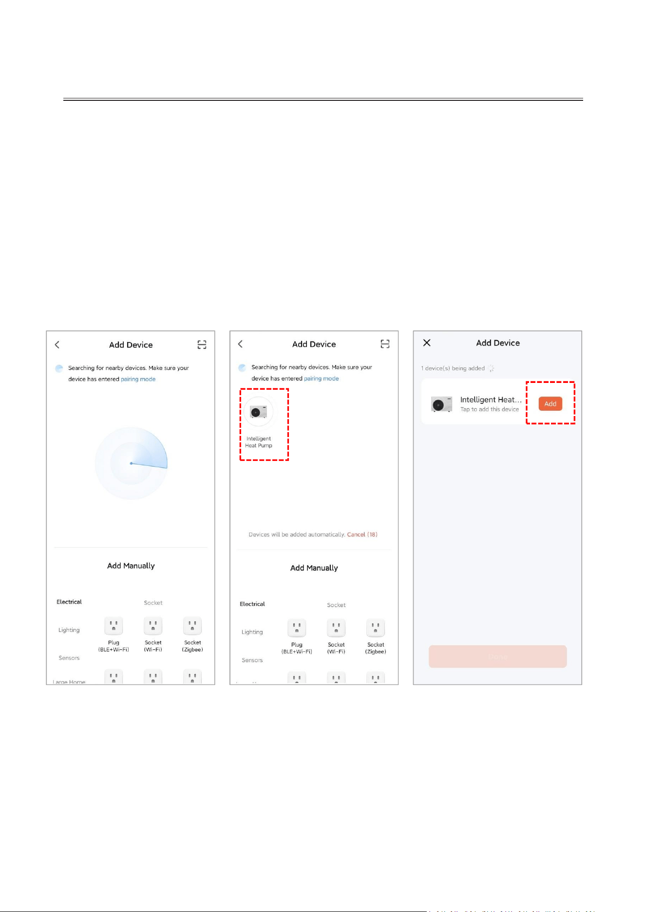
Automatic Search: Ensure Bluetooth is enabled on your phone. The app will
automatically begin scanning for nearby equipment.
Connect:
Once your heat pump is detected, tap the "Intelligent Heat Pump" icon.
Tap the "Add" button next to the device icon.
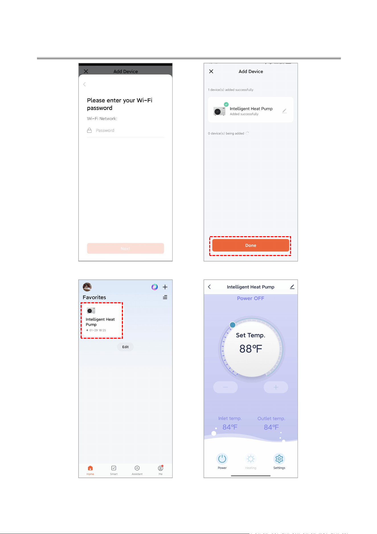
Finalize Setup: Follow the remaining on-screen prompts and tap "Next" to complete
the pairing process.
Automatic Search
Tap Unit Icon
Tap Add Button
APP CONTROL
support@blueplenum.com | www.blueplenum.com | BluePlenum All Rights Reserved
44
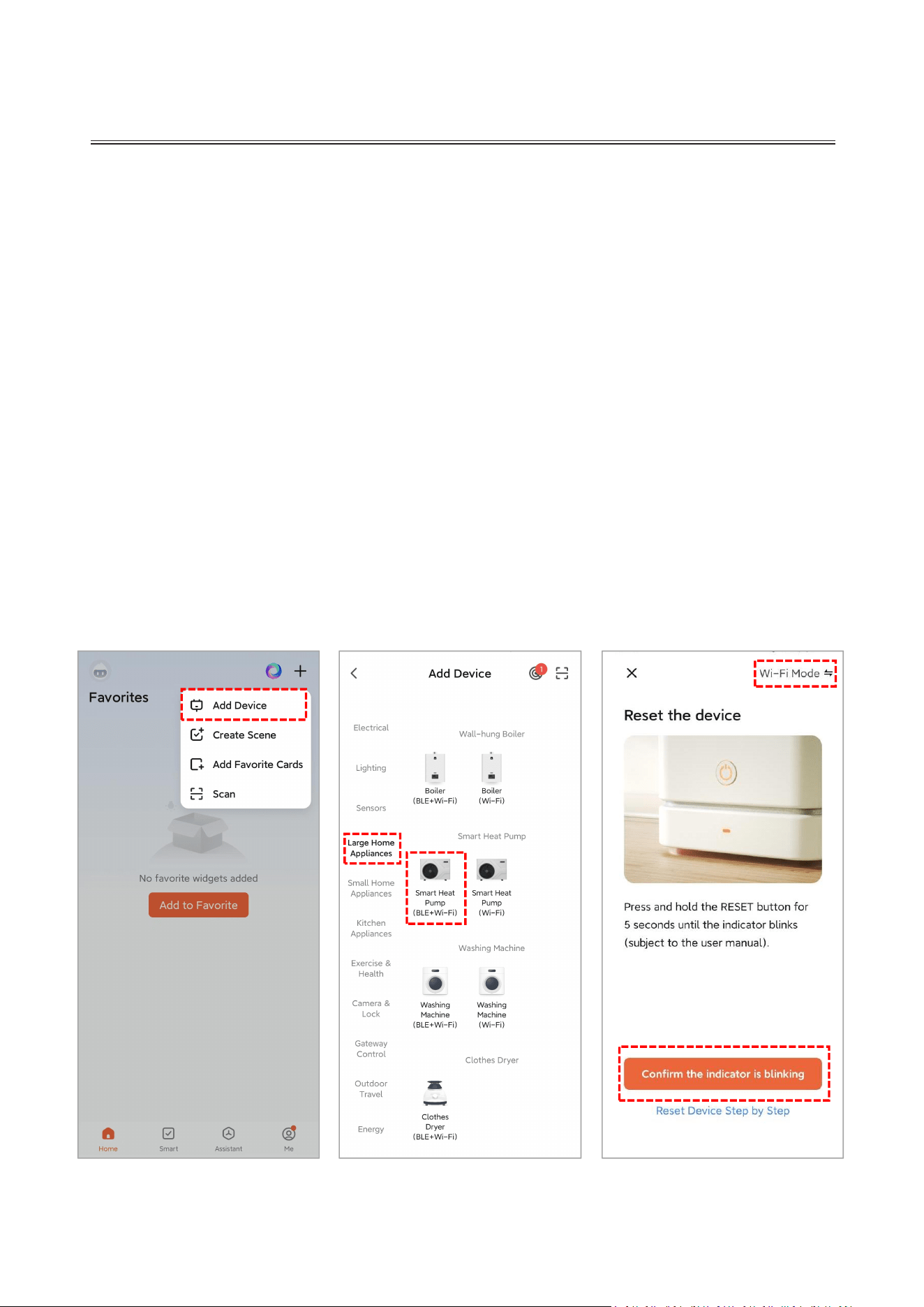
3. Manual Connection (Optional)
Wi-Fi Mode
(1) On the control panel:
Tap "Function" on the main screen.
Select "WIFI Network" to enter the configuration menu and choose "Smart Network
Configuration" .
(2) On the Tuya Smart app:
Launch the Tuya Smart app and ensure you are on the Main Dashboard.
For a successful pairing, please stand next to the heat pump with your mobile device.
Tap the "+" icon in the top-right corner and select the "Add Device" button.
Select "Large Home Appliances" and then tap "Smart Heat Pump (BLE+Wi-Fi)."
Verify the Wi-Fi icon on the control panel is flashing rapidly and that "Wi-Fi Mode" is
displayed in the upper-right corner. Then, tap the "Confirm the indicator is blinking"
button in the app to proceed.
Add Device
Enter
"
Large Home
Appliance
"
Tap Confirm Button

APP CONTROL
support@blueplenum.com | www.blueplenum.com | BluePlenum All Rights Reserved
45
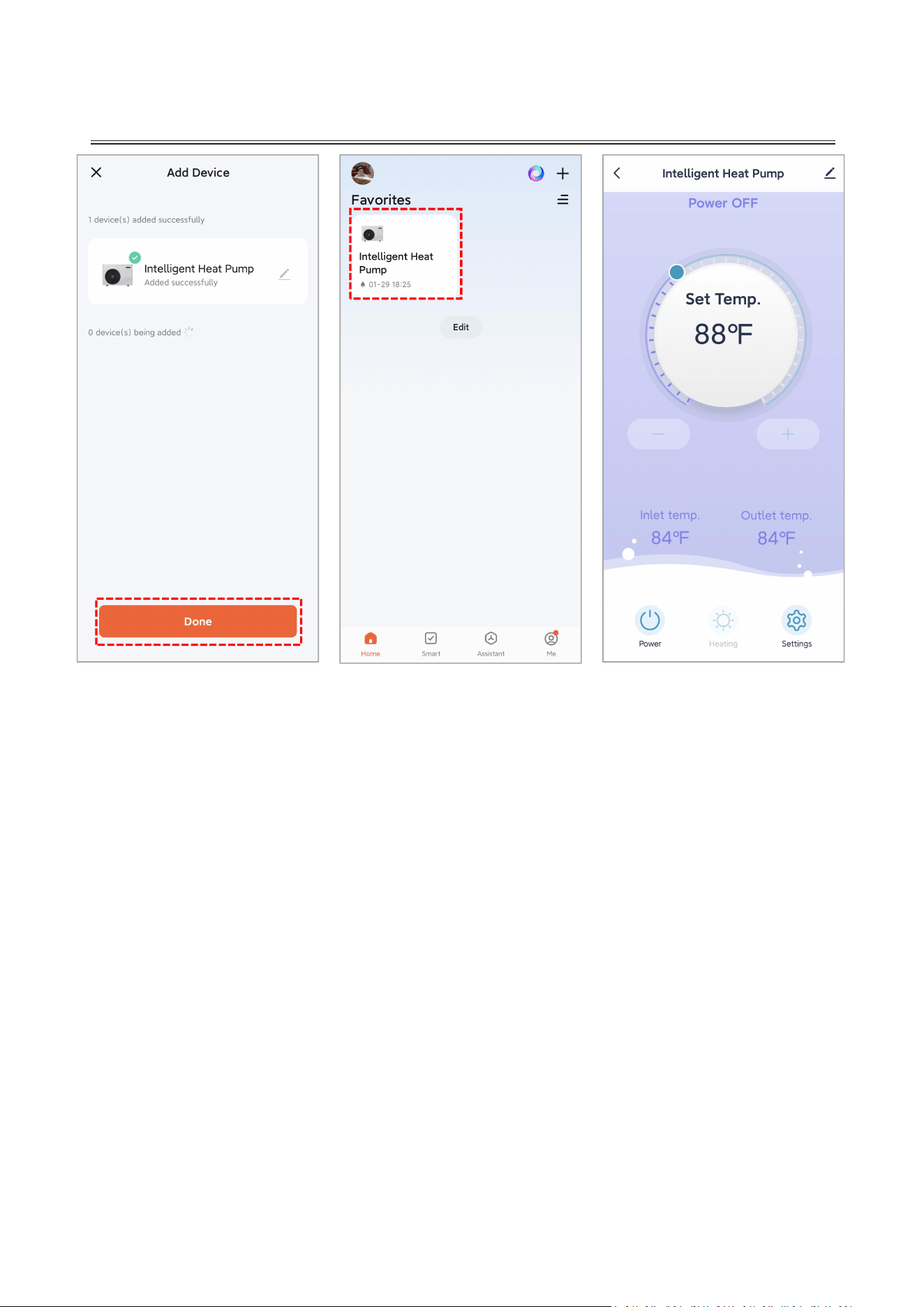
Tap the "Blink Quickly" button.
Enter your Wi-Fi password and wait for the device to pair. Follow the remaining on-screen
prompts to complete the setup.
Choose
"Blink Quickly"
Enter Wi-Fi Password
Connecting
BluePlenum Office
APP CONTROL
support@blueplenum.com | www.blueplenum.com | BluePlenum All Rights Reserved
46
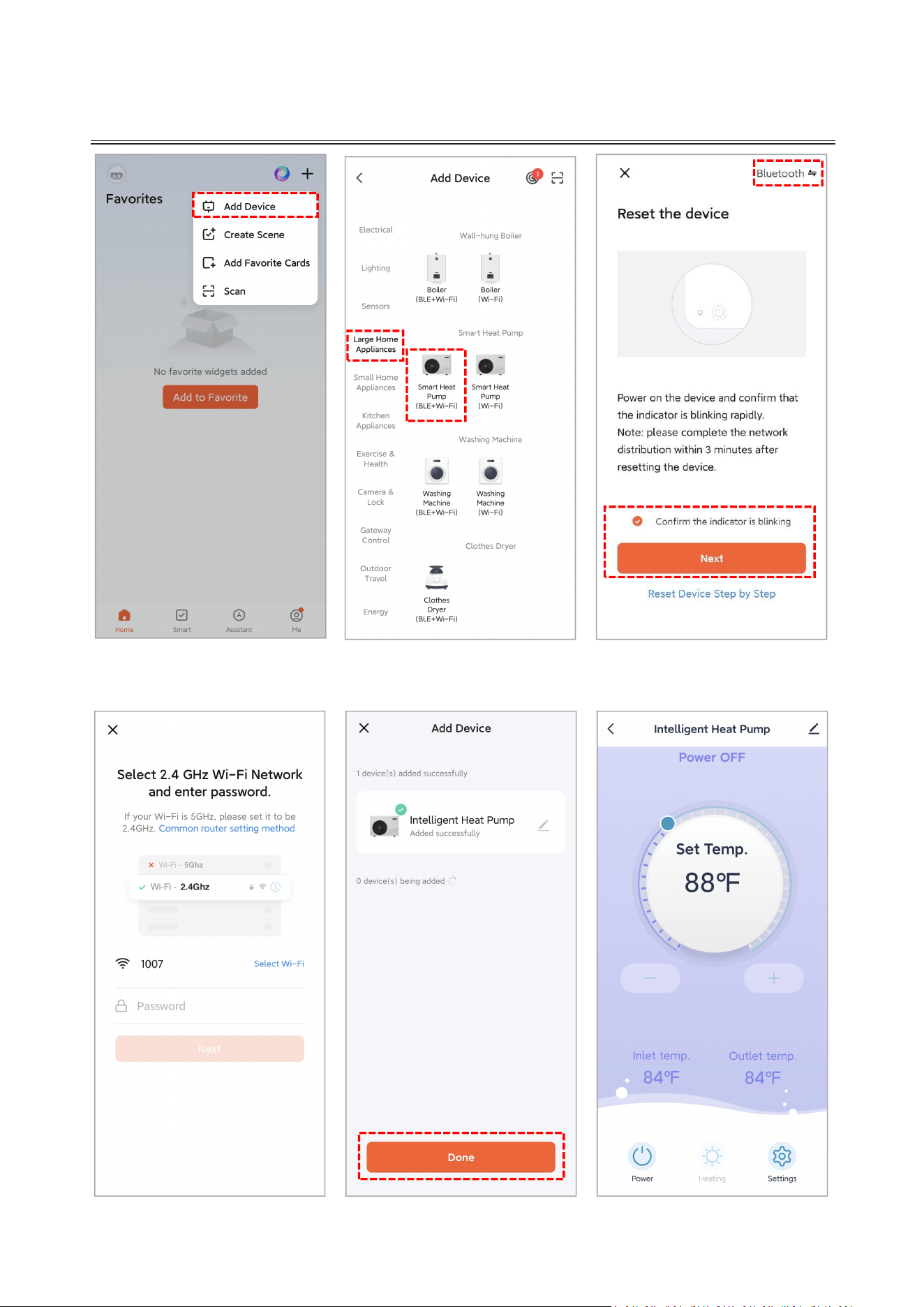
Bluetooth
(1) On the control panel:
Tap "Function" on the main screen.
Select "WIFI Network" to enter the configuration menu and choose "Smart Network
Configuration" .
(2) On the Tuya Smart app:
Launch the Tuya Smart app and ensure you are on the Main Dashboard.
For a successful pairing, please stand next to the heat pump with your mobile device.
Tap the "+" icon in the top-right corner and select the "Add Device" button.
Select "Large Home Appliances" and then tap "Smart Heat Pump (BLE+Wi-Fi)."
Verify the Wi-Fi icon on the control panel is flashing rapidly and that "Bluetooth" is
displayed in the upper-right corner.
Check the "Confirm the indicator is blinking" and tap the "Next" button.
Enter your Wi-Fi password and wait for the device to pair. Follow the remaining on-screen
prompts to complete the setup.
Pairing Successful
Tap Done Button
Enter Control
Dashboard
APP CONTROL
support@blueplenum.com | www.blueplenum.com | BluePlenum All Rights Reserved
48
Note: Automatic On/Off schedules can be set on both the control panel and the
mobile app. Please be aware that these two schedules do not synchronize; however, the
heat pump will execute commands from both sources simultaneously.
Example Scenario: If your Control Panel is scheduled for 6:00 PM – 8:00 PM and your App
is scheduled for 5:00 PM – 9:00 PM, the unit will operate as follows:
5:00 PM: The unit receives an "On" command from the App and begins operation.
6:00 PM: The unit receives an "On" command from the Control Panel and remains running.
8:00 PM: The unit receives an "Off" command from the Control Panel and stops working.
9:00 PM: The unit receives an "Off" command from the App and remains off.
The unit runs from 5:00 PM – 8:00 PM. We recommend using the Tuya Smart APP to
manage all timer settings.
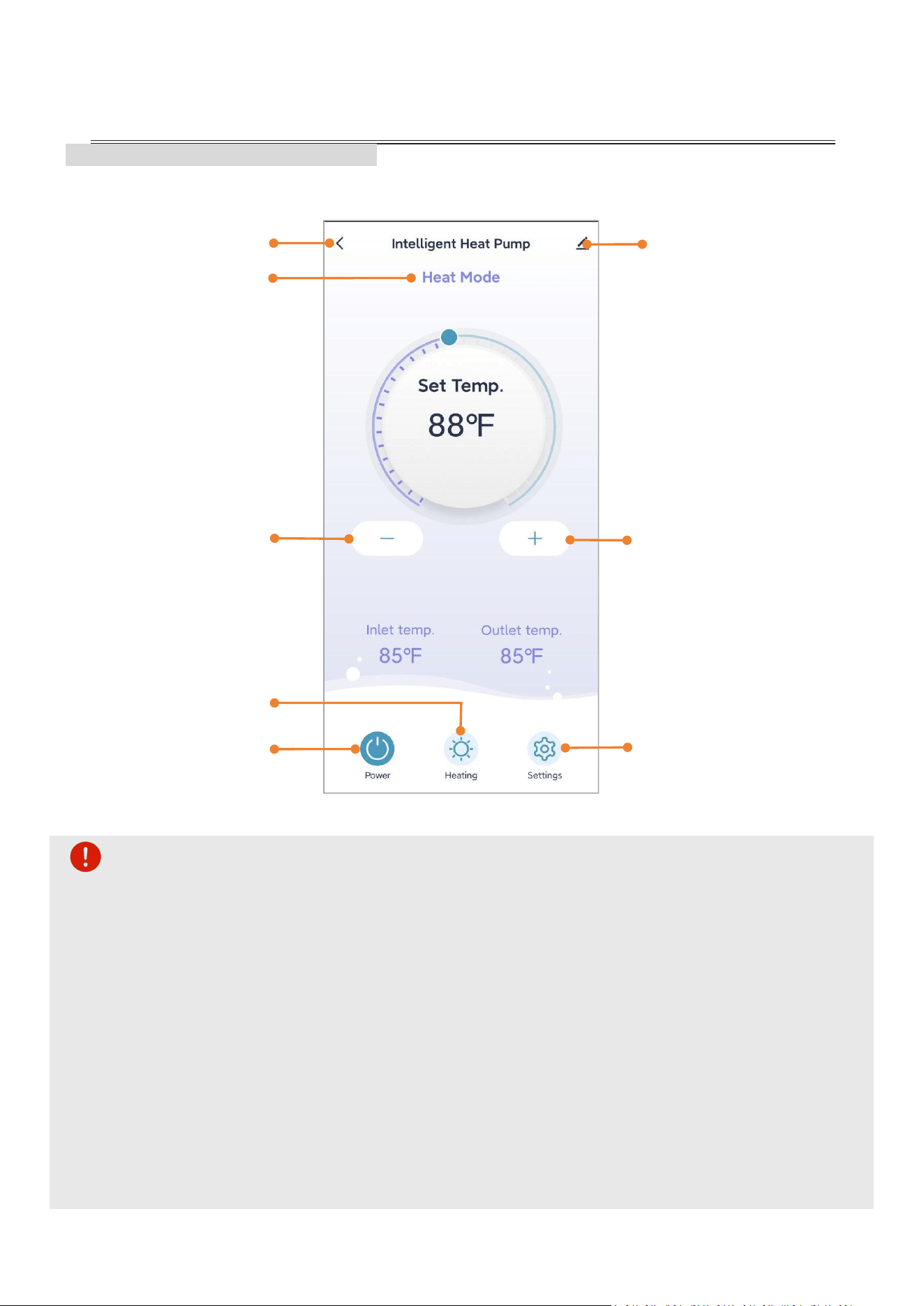
5.4 TUYA SMART APP FUNCTIONS
Open the Tuya Smart app and tap the "Intelligent Heat Pump" icon to access the main
control dashboard.
Reduce Target
Temperature
Current Mode
Timer Settings
Add timer: set repeat options,
set power status(ON/OFF)
Edit or delete timer
Back
Device Settings
Rename device
View device information
Monitor network connectivity
Share device to others
Create device groups
Manage message notification
Settings
Increase Target
Temperature
Choose Mode
ON/OFF Button
TROUBLESHOOTING
support@blueplenum.com | www.blueplenum.com | BluePlenum All Rights Reserved
49
6. TROUBLESHOOTING
Error Code
Analysis
Troubleshooting
1
E03 Water Flow
Protection
1. Low water flow
1.1 The water system is blocked.
1.2 Water pump is not suitable.
1.3 Water pipe is small.
1.4 The water flow switch is stuck and cannot
be reset.
1. Low water flow
1.1 Clean or replace the blocked part.
1.2 Change the pump according to the water flow
and water head.
1.3 Change the water pipe.
1.4 Reset the water flow switch manually.
2. No water flow
2.1 The valve is not open.
2.2 The water pump is not working.
2.3 Water pump failure.
2. No water flow
2.1 Open the valve.
2.2 Turn on the pump.
2.3 Need to replace the water pump.
3. The connection between water flow switch
and main board is poor.
3. Reconnect the water flow switch cable.
4. The water flow switch is installed wrong.
4. Install the water flow switch in the correct
way.
5. Water flow switch failure.
5. Need to replace the water flow switch.
6. Main board failure.
6. Need to replace the motherboard.
2
E05 High Pressure
Protection
1. Poor condensing
1.1 Water temperature is too high (over range
operation).
1.2 Low water flow
1.2.1 The valve in water system is not open.
1.2.2 Waterway blockage, may appear in the
heat exchanger or valve part.
1.2.3 Improper water pump selection.
1.2.4 The water pump is broken .
1. Poor condensing
1.1 Operate within the allowable range.
1.2 Low water flow
1.2.1 Open the valve.
1.2.2 Clean the blocked part or replace it .
1.2.3 Change the pump according to the water
flow and water head.
1.2.4 Replace the water pump.
2.Loose wiring or poor connection of high
pressure switch.
2. Reconnect the wire.
3.There is something wrong with high pressure
switch.
3. Replace the high pressure switch.
4.Main board is broken.
4. Replace the main board.
5. Refrigerant system error.
5.Contact the after-sales service center and
have it sent back for repair.
3
E06 Low Pressure
Protection
1. Poor evaporation effect
1.1 Improper installation position.
1.2 Dust, foreign body blockage on the fin heat
exchanger, etc.
1.3 Fan failure causes abnormal air inlet.
1. Poor evaporation effect
1.1 Readjust the position, the distance of the heat
pump from the wall should not be too close.
1.2 Clean up the dust and dirty matter on the fin
heat exchanger.
1.3 Replace the fan.
2. The connection between low pressure
switch and main board is poor.
2. Reconnect the low pressure switch cable.
3.There is something wrong with low pressure
switch
3. Replace the low pressure switch.
4. Main board is broken.
4. Replace the main board.
5. Refrigerant system error.
5.Contact the after-sales service center and
have it sent back for repair.
4
E09
Communication
fault
1.The connection between wire controller and
main board is poor.
1. Reconnect the wire controller cable.
2. Communication wire and strong electricity
wire put together, resulting in power
interference communication.
2. Communication wire is placed separately from
the strong electricity wire.
3.Control panel fault.
3. Replace the control panel.
4. Main board fault.
4. Replace the main board.
5
E12 Exhaust
Temperature too
high protection
1. Low water flow
1.1 The water system is blocked.
1.2 Water pump is not suitable.
1.3 Water pipe is small.
1.4 The water flow switch is stuck and cannot
be reset.
1. Low water flow
1.1 Clean or replace the blocked part.
1.2 Change the pump according to the water flow
and water head.
1.3 Change the water pipe.
1.4 Reset the water flow switch manually.
2. No water flow
2.1 The valve is not open.
2.2 The water pump is not working.
2.3 Water pump failure.
2. No water flow
2.1 Open the valve.
2.2 Turn on the pump.
2.3 Need to replace the water pump.
3.Temp.sensor fault.
3.Need to replace the T3 temp.sensor.
4.Water flow switch fault.
4.Need to replace the water flow switch.
5.Leakage happen,and refrigerant is not
enough .
5.Repair the leakage,and refill the refrigerant
according to the nameplate.
TROUBLESHOOTING
support@blueplenum.com | www.blueplenum.com | BluePlenum All Rights Reserved
50
Error Code
Analysis
Troubleshooting
6
E15 T4 Water inlet
temperature
sensor fault
1. The connection between the temp. sensor
and the main board is poor.
1.Reconnect the T4 temp.sensor cable.
2. Temp. sensor fault.
2.Replace the T4 temp.sensor.
3.The sensor resistance on the main board
fault.
3.Replace the main board.
7
E16 T7 Internal
coil temperature
sensor fault
1. The connection between the temp. sensor
and the main board is poor.
1.Reconnect the T7 temp.sensor cable.
2. Temp. sensor fault.
2.Replace the T7 temp.sensor.
3.The sensor resistance on the main board
fault.
3.Replace the main board.
8
E18 T3 Exhaust
temperature
sensor fault
1. The connection between the temp. sensor
and the main board is poor.
1.Reconnect the T3 temp.sensor cable.
2. Temp. sensor fault.
2.Replace the T3 temp.sensor.
3.The sensor resistance on the main board
fault.
3.Replace the main board.
9
E21 T1 Ambient
temperature
sensor fault
1. The connection between the temp. sensor
and the main board is poor.
1.Reconnect the T1 temp.sensor cable.
2. Temp. sensor fault.
2.Replace the T1 temp.sensor.
3.The sensor resistance on the main board
fault.
3.Replace the main board.
10
E29 T2 Suction
temperature
sensor fault
1. The connection between the temp. sensor
and the main board is poor.
1.Reconnect the T2 temp.sensor cable.
2. Temp. sensor fault.
2.Replace the T2 temp.sensor.
3.The sensor resistance on the main board
fault.
3.Replace the main board.
11
E38 Fan Failure
1.Power fluctuation. If the power is cut off, it
will be restored within 30 seconds.
1.Turn off the power switch and wait for at least
one minute before reconnecting the power.
2. Fault or loosening of the connection line
between the fan and the PCB
2.Check the connection of the wiring or replace
the wiring.
3.The PCB has malfunctioned.
3.Replace the main board.
4.The fan motor has malfunctioned.
4.Replace the fan motor.
12
E88 Drive
feedback failure
1.There are abnormalities in the power input
and voltage.
1.Make sure the current and voltage inputs are
normal.
2. The PCB is damaged.
2.Replace the main board.
3.Compressor malfunction.
3.Contact the after-sales service center and have
it sent back for repair.
MAINTENANCE
support@blueplenum.com | www.blueplenum.com | BluePlenum All Rights Reserved
51
Warning: RISK OF ELECTRICAL SHOCK. Always disconnect the power
supply before performing any maintenance or cleaning to ensure personal safety.
7. MAINTAINANCE
7.1 WINTERIZING
To protect your investment during freezing temperatures, please follow these essential
steps:
Drain All Water: Thoroughly drain the unit to prevent internal freezing. Ice expansion
can cause irreversible structural damage and may void your warranty.
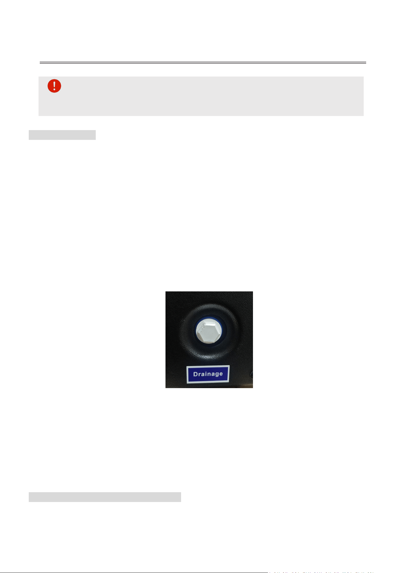
Pro Tip: Loosen the water inlet and outlet unions with a wrench and remove the
drainage cap(see figure below) to allow all residual water to escape. This is critical
for protecting the titanium heat exchanger.
Note: Some models have removed the drainage port due to upgrades; the water inside the
unit can be drained directly through the water inlet and outlet.
Clear Condensation Drains: Ensure all condensation drainage paths are unobstructed.
If ambient temperatures drop below 41°F (5°C), remove the rubber drain plug to
ensure proper drainage and prevent ice buildup.
Install Protective Cover: Use our heavy-duty, UV-resistant, and waterproof cover
to shield the unit from snow, debris, and harsh winter elements. Note: Ensure the
power is off and the unit is dry before covering.
7.2 ROUTINE CLEANING PROCEDURES
Keep your heat pump running efficiently with these regular maintenance steps:

MAINTENANCE
support@blueplenum.com | www.blueplenum.com | BluePlenum All Rights Reserved
52
Exterior Care: Wipe the outer casing with a soft, damp cloth. Do not use detergents,
abrasive cleaners, or harsh chemicals, as these may damage the protective finish.
Evaporator Coil: The evaporator located at the rear of the unit must be kept clear of
debris. Use a vacuum with a soft brush attachment to gently remove dust and leaves
without bending the fins.
Filtration System: Regularly inspect and clean the pool filters. A clogged filtration
system restricts water flow and can cause the unit to malfunction or shut down.
Clear Airflow: During extreme weather, ensure the air intake and exhaust outlets are
free of ice, snow, or debris to maintain proper airflow and performance.
7.3 ANNUAL INSPECTIONS
Comprehensive Safety Check: Full inspection of all mechanical components and
safety controls.
Electrical Audit: Verify the integrity and tightness of all electrical connections and
wiring.
Startup Analysis: Test all startup components and run cycles to ensure operational
stability.
Refrigerant & Pressure Check: Monitor refrigerant levels and system pressure. If
levels are low or leaks are detected, a certified technician must handle the repairs.
Winter Protection: Utilize our heavy-duty, UV-resistant, and waterproof cover
during the off-season to protect against the elements.
Pre-Season Restart: Always verify adequate water flow through the system before
restarting the unit for the season to prevent dry-firing or damage.

WARRANTY
support@blueplenum.com | www.blueplenum.com | BluePlenum All Rights Reserved
53
8. WARRANTY
8.1 TWO-YEAR WARRANTY
BluePlenum warrants its products to the original retail purchaser to be free from defects in material
and workmanship, under normal use and service, for a period of two (2) years from the date of
purchase. This limited warranty is subject to the terms and conditions outlined below.
1. During the warranty period, BluePlenum will, at its discretion:
Local Service Centers & Free Remote Technical Support
Ship replacement parts at no cost
Replace the entire unit if it is determined to be non-operational due to a manufacturing defe
ct
2. Warranty service is primarily conducted through remote diagnosis—including video calls, photo
reviews, and system data analysis. For free hands-on support, local service centers are
available (headquartered in California); please contact us for a complete list of authorized
service addresses.
3. Coverage: This warranty covers the repair or replacement of any components verified to be
defective in materials or workmanship under normal use and service.
4. To ensure proper performance and warranty coverage, the product must be:
Installed according to the BluePlenum installation manual
Used with proper electrical supply, plumbing, and water flow
Maintained in accordance with normal pool equipment practices
5. This limited warranty does not cover issues caused by:
Improper installation, wiring, plumbing, or voltage mismatch
Use outside the recommended operating conditions
Freeze damage, flood damage, lightning, or other acts of nature
Water chemistry imbalance, corrosion, scale buildup, or debris blockage
Unauthorized modification, misuse, or neglect
6. This warranty covers parts and product replacement only.
It does not include:
Labor, installation, removal, or re-installation costs
Shipping costs outside the continental United States
Consequential or incidental damages
7. How to Obtain Warranty Service:
To initiate a claim, please contact our support team at support@blueplenum.com or visit our
website at https://www.blueplenum.com/pages/contact to submit a formal service request.
WARRANTY
support@blueplenum.com | www.blueplenum.com | BluePlenum All Rights Reserved
54
NOTE: In no event shall BluePlenum's liability exceed the original purchase price of
the product. For the most current warranty terms and updates, please visit our website
or contact our support team directly. BluePlenum is committed to delivering exceptional
after-sales service to ensure your total satisfaction.
8. Post-Warranty Support:
Even beyond the warranty period, BluePlenum is here for you. If you encounter any issues with your
product, our dedicated support team is ready to provide expert guidance and practical solutions to
keep your system running smoothly.
Service Item
First 2 Years
After 2 Years
Online Technical
Support
FREE
(Video calls / Data review)
FREE
(Video calls / Data review)
Local Service Center
Support
FREE
(Authorized locations)
FREE Support;
parts/consumables may apply
Replacement Parts
FREE
Charged at cost
Shipping Costs
FREE
(Covered by BluePlenum)
Covered by Customer
If you are unsure whether an issue is covered, please contact our support team.We are always ha
ppy to help you find the most practical and fair solution.

Website: https://www.blueplenum.com
Email: support@blueplenum.com
Customer Service Opening Hours: 24/7/365
Tech Support Opening Hours:
PDT (-7): 6 PM - 7AM, Sunday Afternoon - Friday Morning
MDT (-6): 7 PM - 8 AM, Sunday Afternoon - Friday Morning
CDT (-5): 8 PM - 9 AM. Sunday Afternoon - Friday Morning
EDT (-4): 9 PM - 10 AM. Sunday Afternoon - Friday Morning
HKT (+8): 9 AM - 10 PM, Monday Morning- Friday Afternoon
Official Store Email Us PDF (EN & ES Version) Tutorial Video

FCC Warnning:
This equipment has been tested and found to comply with the limits for a Class B digital device,
pursuant to part 15 of the FCC Rules. These limits are designed to provide
reasonable
protection againstharmful interference in a residential installation. This equipment generates,
uses and can radiateradio
frequency
energy
and,
if
not
installed
and
used
in
accordance
with
the
instructions,
maycause
harmful
interference
to
radio
communications.
However,
there
is
no
guarantee
thatinterference
will
not
occur
in
a
particular
installation.
If
this
equipment
does
cause
harmfulinterference to radio or television reception, which can be
determined by turning the equipmentoff
and
on,
the
user
is
encouraged
to
try
to
correct
the
interference
by
one
or
more
of
thefollowing measures:
•
Reorient or relocate the receiving antenna.
•
Increase the separation between the equipment and receiver.
•
Connect the equipment into an outlet on a circuit different from that to which the receiver is
connected.
• Consult the dealer or an experienced radio/TV technician for help.
Caution:
Any
changes
or
modifications
to
this
device
not
explicitly
approved
by
manufacturer
could void your authority to operate this equipment.
This
device
complies
with
part
15
of
the
FCC
Rules.
Operation
is
subject
to
the
following
two
conditions:
(1)This
device
may
not
cause
harmful
interference,
and
(2)
this
device
must
accept
any
interference received, including interference that may cause undesired operation.
This
equipment
complies
with
FCC
radiation
exposure
limits
set
forth
for
an
uncontrolled
environment.
This
equipment
should
be
installed
and
operated
with
minimum
distance
20cm
between the radiator and your body.