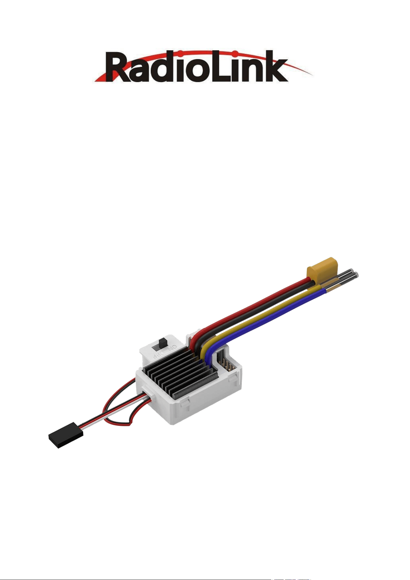
COOL 9030
(B rus hed ESC for Cars & Boa ts )
Use r Manu al
Radio Li nk Bru she d ESC
(Sin gle -moto r & Dua l-m otor Cli mbi ng Veh icle s / Drif t Car s / Craw lers / Tr ail ers /
Bait B oats / Re scu e Boat s / Surv eyi ng Bo ats)
Note: This manual only introduces the basic usage of RadioLi nk CO OL 9030 brushed ESC. For more details,
please access to RadioLink website: https://www .radiolink.c om/cool9030 or send emails to:
after_service @radiolink.c om.cn

1
Contents
Safety Precautions ------- --------- --------- -------- --------- -------- --------- -------- --------- -------- --- 2
Part 1. Introduction of COOL 9030 ------- --------- -------- --------- -------- --------- -------- --------- - 2
1.1 COOL 9 030 Overvie w ---- -------- --------- -------- --------- -------- --------- -------- --------- -- 2
1.2 Specifications -------- -------- --------- -------- --------- --------- -------- --------- -------- ------- 3
Part 2. Connection of COOL 9030 -------- --------- -------- --------- -------- --------- -------- --------- - 4
2.1 Power Input - -------- --------- -------- --------- -------- --------- --------- -------- --------- -------- 5
2.2 Motor output - -------- --------- -------- --------- -------- --------- -------- --------- --------- ------ 6
2.3 Signal i nput ------- --------- -------- --------- -------- --------- --------- -------- --------- -------- -- 6
Part 3. Throttle calibration - --------- -------- --------- -------- --------- -------- --------- -------- -------- 7
Part 4. Usage o f Jumper Cap - --------- -------- --------- --------- -------- --------- -------- --------- ----- 8
Part 5. ESC status ---------- --------- --------- -------- --------- -------- --------- -------- --------- -------- - 10
5.1 Motor sound -------- --------- -------- --------- -------- --------- --------- -------- --------- ------ 10
5.2 Indicator light --------- --------- -------- --------- -------- --------- -------- --------- -------- ----- 11
5.3 Mixed prompt of motor and light ------- --------- -------- --------- -------- --------- ------- 11
2
Safety Precautions
1.Please make sure that all wires and connecting parts a re well in sulated befo re connecting the ESC to
related parts. Shor t-circuiting w ill damage the ESC.
2.Please read the man uals of all the pow er equipmen t and th e frame carefully before using the ESC to
ensure that the power is reasonably matched, and avoid the motor overload due to the wrong power
combination , which will eventu ally damage the E SC.
3.Please carry out wiring and debugging when the car is suspended for your sa fety and others'.
4.Please disconnect the battery and ESC after use. If the batt ery is n ot disconnected, even if the ESC
switch is turn ed off, the ESC wi ll continue to consume power. If the battery is connect ed for a long time
without use, the battery w ill eventually be completely discharg ed, which will cause the malfunct ion of the
battery or ESC.
RadioLink is not responsible for any dama ge caused by incorrect oper ation!
Part 1. Introduction of COOL 9030
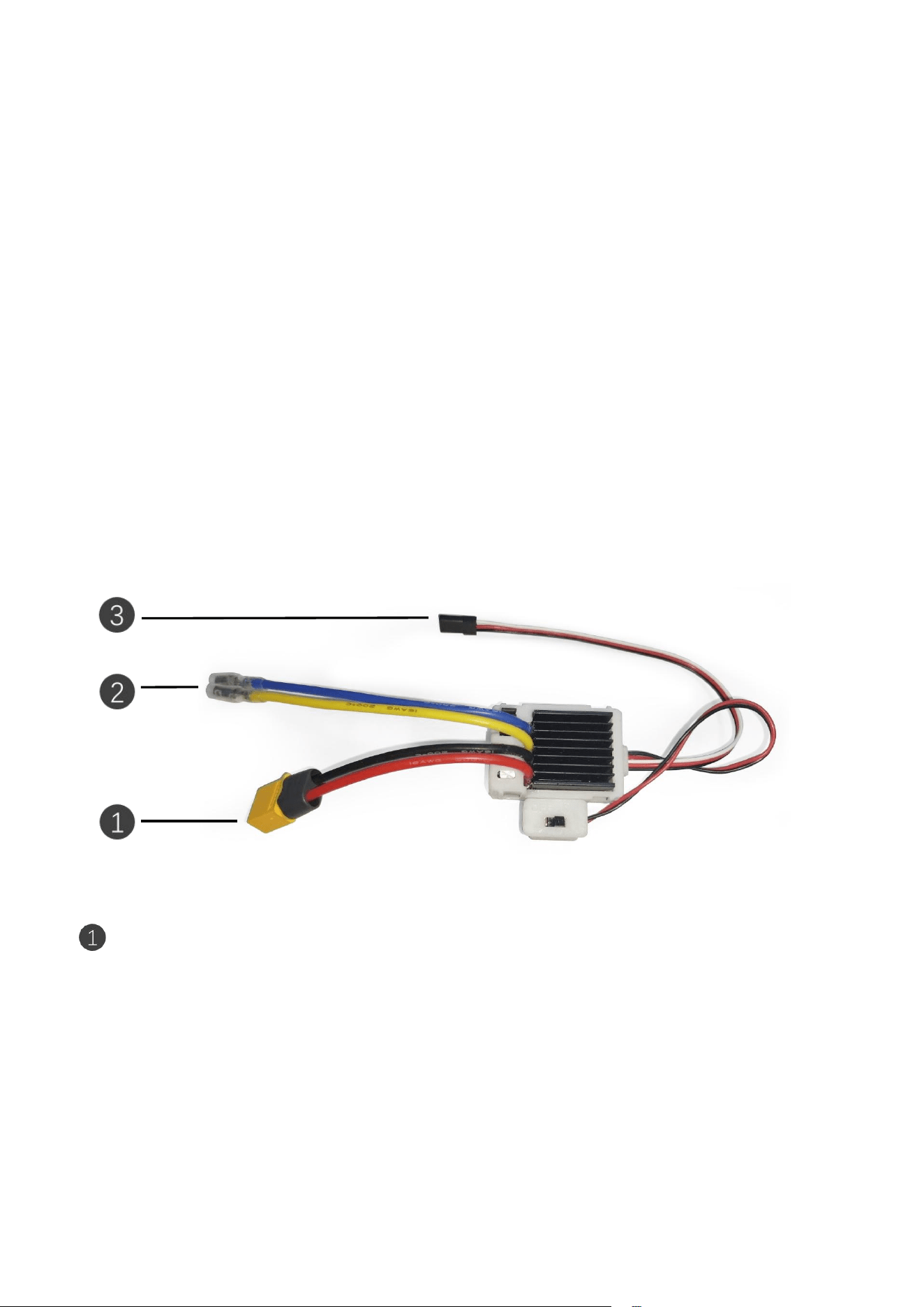
1.1 COOL 9030 Overview
Power in put: The po wer input of the ESC is connected to the pow er supply. At the sa me time, the
voltage range of conn ected power supply should be within th e range of 6~16.8V (for non-lithiu m batteries:
NI-MH battery , nickel-cadm ium batteries and lead-acid batteries, etc.), and 6-18V (for lithium batteries).
Power supply ou tside this voltage ra nge cannot guara ntee the stability of the system.
Note: Except the voltage range, l ithium batteries and non-lithiu m batteries have different using
instructions. When using a lithium battery, please insert jumpe r cap 3 of COOL 9030; When using a
non-lithium battery, pleas e remove jumper cap 3. If the status of the jumper cap 3 does not match th e actual
battery used, the battery ma y be seriousl y over- discharged and dama ged. Be sure to confirm the battery type
of the ESC and check jump er cap status before use. For more details, please refer to Pa rt 4. U sage of Jumper
Cap.
3
Motor output: The motor connec tor is used to connect a brus hed DC motor. At the same time, the
rated w orking voltage of the connected bru shed DC motor must meet the power supply voltage ran ge of the
ESC. Otherw ise the stable operatio n of the ESC and the connec ted motor can not be guarante ed.
Signal input: The si gnal input is used to connect th e PWM signal i nput(single cha nnel sign al of the
receiver) to the ESC. At the sa me tim e, the connec tor has a BE C outpu t function. The output voltage of BEC
can supply power to the receiver or servo. (T he maximum current is 5A)
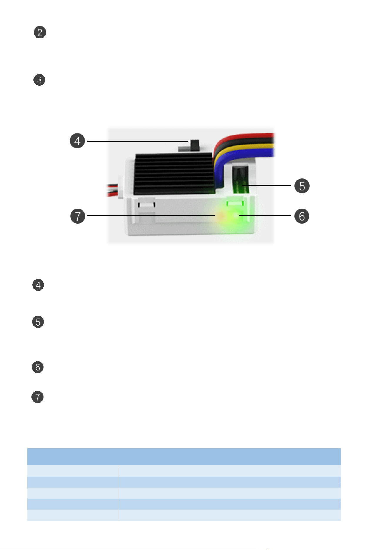
Switch introd uction:
Control switch: The cont rol s witch is used to control the workin g sta te of the E SC. When the switch is
turned on, the ESC starts to work, w ith the outp ut voltage of 5.5V or 7.5V. When the switch i s turned off, the
ESC stops workin g,with no outp ut voltage.
Jumper ca p: The jumper cap is used to select th e operating mode of the ESC, the typ e of input power
supply, and the output voltage of B EC. Detai ls will be in troduced later.
LED light descrip tion:
Power light: The pow er l ight is used to in dicate the current sel f-check and power supply s tatus of the
ESC system. The color of the light is green. Detai ls will be introduced later.
Status lig ht: The status lig ht is used to indicate the current self-check a nd operating status of the ESC
system. The color of the light is red. Details w ill be introduced later.
1.2 Specifications
Specifications of COOL 9030
Dimensions:
46.6*35.6*21mm
Weight:
49g
Compatible models
All cars & Boats
Constant Current:
90A@18V
BEC Voltage:
4
Peak Current:
100A
Input Voltage:
6~16.8V (NI-MH, Ni-Cd or lead -acid battery);6~18V (Lithium Battery)
Low Voltage Protection:
6.5V@2S , 9.75V@3S ,13 .0V@4S
Maximum Continuous
Working Temperature of PCB:
100℃
Plug Input:
XT60
Plug Output:
Receptacle connectors
Motor Limit:
Brushed Motor Limit with 38 0/540/550/560/570
Internal Resistance:
7 milli-ohm
Drive Frequency:
PWM frequency 2KHz
Part 2. Connection of COOL 9030
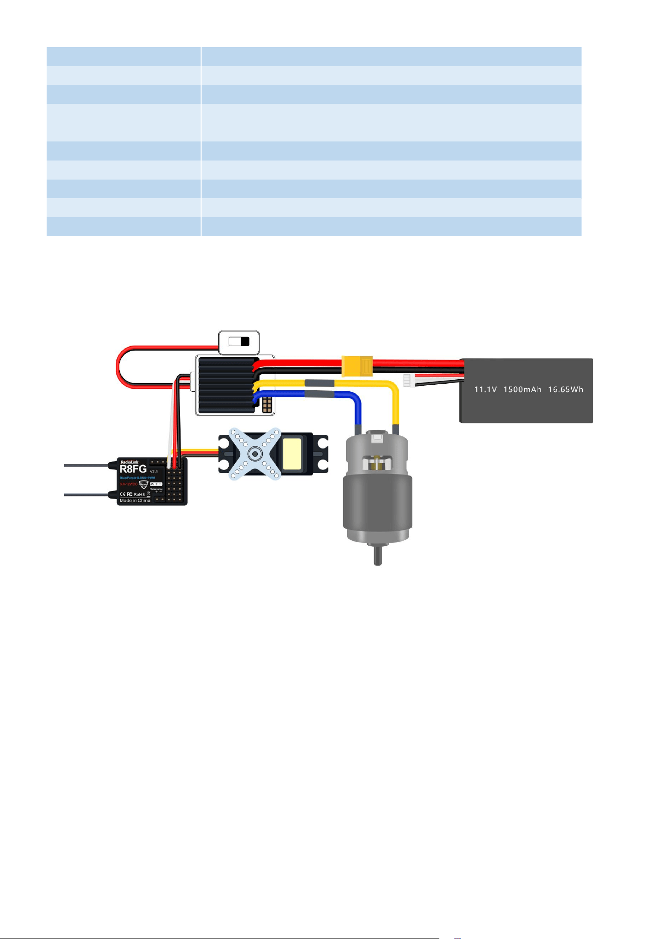
Connect the si gnal cable of the ESC with the receiver correctly befo re use. T hen connect the motor output
cable of the ESC with the motor accuratel y (You can ch oose the connec tion direction based on actual usage.).
Make sure the ne gative and positive po les of the power in put cable are not reve rsed.
Connection to the receiver : Pl ug the receiver connection cable of the ESC into the throttle channel of the
receiver. The receiver connec tion cable of the ESC outputs the voltage of 5.5V to the receiver and the servo, s o
please do not supply additional pow er to the receiver. Other wise the ESC m ay be damaged.
Connection to the motor: T here is no pos itive or neg ative connection bet ween the brushed motor an d the
ESC. If th e motor tu rns incorr ectly, you can directly change the direc tion of th e motor through th e servo
phase in the menu of the transmitt er, or exchange the connec tion of the two motor output cabl es of ESC.
Make sure the right connection a nd good contact between the motor an d the ESC.
Connection to the battery: The battery connection cable of the ESC has positive and negative poles. When
connecting th e battery, plea se make s ure that the (+) positive pole of the cable is connected to the (+) positive
pole of the batt ery, an d the (-) negative pole is connected to th e (-). If the ESC is connected reversely, it wil l be
damaged. Warranty service w ill n ot be provid ed if the ESC is damag ed due to the reverse connection of the
power supply.

5
2.1 Power Input
This brushe d DC ESC suppo rts two types of batteries a s power supply, in cluding n on-lithium batteries(
NI-MH battery , nickel-cadm ium batteries and lea d-acid batteries, etc.) and lithium batteries(pol ymer lithium
batteries). At the same tim e, in order to make sure the stability of the s ystem, the voltage of the input power
supply must be within the range of 6.0V to 16.8V (6V to 18 V under the li thium battery mode).
The protectio n wa ys to the batt ery voltage are differ ent when two types of batteries are used as power supply
separately.Pl ease check the below table for details:
Battery type
Under-voltage
protection
Half-power
protection
Over-voltage
protection
2S lithium battery
6.0 V
6.5 V
8.7 V
3S lithium battery
9.0 V
9.75 V
13.05 V
4S lithium battery
12.0 V
13.0 V
17.4 V
Non-lithium battery
6.0 V
6.5 V
16.8 V
Note: In the table, the under-vo ltage protec tion value an d hal f-power protection value of the lithium battery
are based on the standard lithiu m battery (4.2V is the maximu m voltage of a sin gle cell of the stan dard lithiu m
battery), but the over-vo ltage protectio n value is based on the standar d high-voltage l ithium battery (4.35V is
the maximum voltage of a single cell of the sta ndard high-v oltage lithium battery ).
The introduct ion of the three cond itions are as follows, including under -voltage protectio n, half-pow er
protection a nd over-voltage prote ction.
1. Under-voltage prote ction: It is an under -voltage protection state. When the voltage of the input pow er is
lower than this value, the ESC will stop the output control of the motor, which means the E SC will not
respond to the input signal at this tim e, an d the power light w ill fl ash to give a remind er. At the same time,
when the ESC en ters the under-voltag e prote ction state a nd the battery voltage rises back to the
half-power protection val ue, the system will exit the under-voltage protection s tate. Then the system wil l
return to normal operation, and the normal output contr ol of the motor is restored.
2. Half-power protectio n: It is half-power output prote ction state. When the voltage of the input power
supply is lower than the va lue, the ESC will reduce the output pow er of the motor to half of the original
(The ESC can still respond to the input signal at th is time). Mean while, when the ESC en ters the half- power
protection sta te and the battery voltage rises to n ear the over-vol tage protection value, the system will not
exit the half-power prote ction state. But when the battery voltag e drops to the under-voltage protection
value, the system w ill exit half-power protection state and enter the und er-voltage protection state, with
no output control of th e motor.
3. Over-voltage prote ction: It is over-voltage pro tection state. When the voltage of the in put power is hig her
than this value, the ESC wil l stop the output cont rol of th e motor, which m eans it w ill not resp ond to the
input s ignal at th is time,and the power light will flash to give a reminder. At the same time, when the ESC
enters the over-vo ltage protec tion state an d the battery voltage drops to below the over-voltage
protection val ue, the system will resume normal operation an d th e normal output control of the motor will
be restored . Then th e system will return to normal operation, and the normal output cont rol of the m otor
is res tored.

6
2.2 Motor output
This brushed DC ESC only support s the op eration and output control of brushed DC motors, an d the
instantaneou s peak val ue of the output current of th e ESC can reach 100A. Therefor e, when usi ng this ESC, a
brushed DC motor must be correctly selected to avoid dam age to the E SC. At the s ame time, the "M+ ” lead
wire of the mot or interface is connected to the positive po le of the motor (usu ally a yell ow or red power
supply line), and the "M-" l ead wire i s connec ted to the negative pole of the motor (usu ally a bl ue or black
power supply li ne).In additi on, the brushed DC m otor load connected to the mot or in terface of the ESC must
not have an additional circuit connection with the in put power port, otherwis e the E SC system wi ll not
operate normal ly.
Regarding the matchin g relationship between the speed of the brushe d DC moto r (conventio nal model ) and
the power battery (conventional l ithium battery a nd Ni-MH battery), plea se refer to the fol lowing table:
Lithium battery
Ni-MH battery
Motor speed
2S lithium battery
5-6S Ni-MH battery
RPM < 30000 , 7.2 V
3S lithium battery
7-9S Ni-MH battery
RPM < 20000 , 7.2 V
4S lithium battery
10-12S Ni-MH battery
RPM < 15000 , 7.2 V
Note: The table is for referen ce only. When in specific application scenario s, user s need to analyze the
concrete cases to prevent the ESC a nd motor from being damag ed or even battery damage a ccidents.
2.3 Si gnal input
The sign al i nput (the throttle signal input) of this brushed DC ESC can only iden tify the PWM signal output by a
single channel of the receiv er. The sig nal with m ultiple channel codes (such as PPM signal s, S.BUS s ignals,
etc.)cannot be reco gnized. At the sam e time, the character istics of the PW M sign al need to m eet the
parameter cha racteristics in th e table below to en sure that the ESC s ystem is stably control led by the control
signal. The param eter characteristic table of the P WM signal is as follows:
Parameters
Minimum
Maximum
PWM signal frequency
7.15 Hz(140 ms)
400 Hz(2.5 ms)
PWM signal amplitude
2.8 V
5.4 V
PWM signal delay
0 ms
150 ms
PWM signal pulse width
0.8 ms(800 us)
2.2 ms(2200 us)
Note: The P WM si gnal delay paramet ers in the above table are used to measure the fault tolerance range of
the ESC system for sud den signal in terruption (loss). The specific value refer s to th e period from the
interruption (loss) of the PWM sign al to the recovery of sign al.

7
This ESC system not only has basic control function s, bu t al so has a response function to a bnormal state of
the control input sign al. Regarding the abnorm al state of control input signal, there are the fol lowing two
situations:
1. No signal inp ut: When the ESC is connected to the power supply, if the thr ottle input signa l is not detected
by ESC or the throttle s ignal delay time exceeds the PWM signa l delay parame ter, the system will identify
the ESC as no sign al input state, and the current abnormal state will be promp ted by the flas hing status
light and the motor beeping at the same time.
2. Abnormal Signal input : when the ESC is conne cted to the power s upply, if the throttle input sig nal is not
within the midpoint range (The factory default setting of mi dpoint is 1500 us, a nd the midp oint ra nge is
within plus or minus 50 us of the m idpoint value, which is 1450 us to 1550 us. When the throttle is
calibrated, the cali bration resu lt shal l prevai l), the system w ill ident ify the ESC as abnormal signal in put
state, an d the current abnormal state will be prom pted by th e flashing status lig ht a nd the motor beeping
at the same time.
Note: When the s ignal i s in an abnormal state, set the th rottle input signa l back to the midpoin t range to
remove the fault prompt.
Part 3. Throttle calibration
This ESC system uses the standard receiver channel signal as a reference by default. Ho wever, unexpected
effects may occur due to the differences in the parame ter settings of each receiver and its remote controll er
(such as servo output ratio an d servo midpoint value, etc .). Ca librate the throttle a t this time so that th e ESC
can be adjusted to the signal output of the rece iver to achieve the expected effect s.
COOL 9030 is a two-way ESC, so the th rottle calibratio n me thod is the sam e as that of the common two-way
ESC. The specific steps are as follows
ESC Calibration Method
Preparation
Connect the ESC, motor, battery, and receiver (Bind the receiver with the
transmitter in advance, and the r eceiver output must be PWM signal output.). Turn
on the transmitter, and keep other devices powered off.
Step 1
Push the throttle stick to the highest position and keep it. Then power on the ESC
and the receiver. The motor will directly beep t wice. (If th e motor does not emit
beep sounds, please refer t o the following precautions)
Step 2
After two beeps, push the throttle stick t o the lowest position and keep it. The
motor will make two beeps again.
Step 3
After two beeps, push the throttle stick to the neutral position and keep it. The
motor will emit a series of beep sound, indicating that the ESC throttle calibration
is completed.
8
Note:
1. The order of th e position of the throttl e stick in th e above calibration pro cess is "the highest posi tion - the
lowest position - neutral position" . If the motor does not directly e mit beep sou nds w hen the th rottle stick
is placed at the highest position, change the order of the posit ion of the throttle stick to "the lowest
position - the highest position - neutra l pos ition" for calibrat ion.
2. Before calibrating , it is best to set the TRIM of th e transmitter to “0 ” to a void unnecessa ry trouble.
Part 4. Usage of Jumper Cap
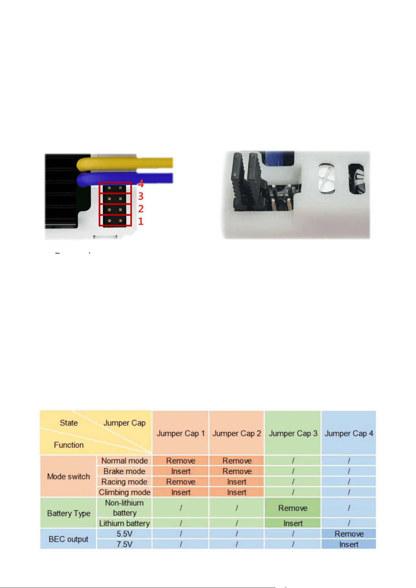
Remove ju mper cap Insert jumper cap 1, 2
This ESC has four sets of jumper cap switches. The serial numbers of the s witches from outside to in side are 1
to 4, as shown in the picture above. Ins ert the jumper cap an d it is connected state. T he 4 sets of switches in
the right pict ure are al l i n the connected state. When the jumper caps are removed, the 4 sets of sw itches are
in th e off state, as shown in the left picture. T he jumper cap is used to se t the operation mode, battery type,
and B EC output voltage . Ju mper cap 1 and 2 are used to s et th e operatio n mod e of the ESC. Jumper cap 3 is
for battery typ e, and jumper cap 4 for B EC ou tput voltage.
The differ ent states of the 4 sets of jumper caps will correspond to the differe nt op eration modes of the ESC.
Choose the operation mode you nee d, determin e the type of the battery you use and the require ments for the
BEC. Then refer to th e following table to set the 4 sets of jumper caps.
Note: The ESC must be resta rted after ch anging the s tate of the jumper cap. O therwise, the corresponding
mode and output will not take effect.
1 2 3 4

9
Mode switch
There are 4 operation mod es of the ESC. Changin g the state of jumper caps 1 and 2 to switch modes. When
the throttle stick is in different posi tions, the response of the motor is al so different. The specific rel ationship
is as shown in the table below:
Jumper Cap 1 &2
Operation
Mode
Pull inward
Neutral
position
Push forward
Both removed
Normal mode
Forward
No operation
Reverse
Jumper Cap 1
inserted only
Brake mode
Brake/Reverse
Jumper Cap 2
inserted only
Racing mode
Brake
Both inserted
Climbing mode
Brake
Reverse
Normal mode: P ull the trigger inward for forward operation, a nd push the trigg er forward for backward
operation. There is n o brake for the tran sition between goin g forward and backward. With l ow heat, this
mode is suitabl e to use in confined spac es.
Brake m ode: It is the comm on mode. P ull the trigger inwa rd for forw ard operation. When the operation of the
trigger is cha nged from pu lling in ward to pushing forward, the ESC will perform the brake operation. Retu rn
the trigg er to the neutr al position at this time, and then push the trigg er forward again . The ESC w ill perform
the reverse operatio n.
Racing mode: Pull the trigger inwa rd f or forward operation, and push the trigger forward for brake op eration.
There is no reverse opera tion on E SC.
Climbing mod e: Pull th e trigger in ward for forwa rd operatio n, and push the trigger forward for reverse
operation, When th e trigger is at the neutra l position, the ESC will perform the brake operation.
Battery Ty pe
When using different types of batteries, ch ange the state of Jumpe r cap 3 to make the battery type match the
actual battery. Insert Jumper cap 3 when using a lithium battery, and remove Jumper cap 3 when using a
non-lithium batt ery. Wrong state of Jump er cap 3 may cause seriou s over-discharge of the battery and
damage the battery . Be sure to check Jumper cap 3 to confir m the battery type of th e ESC before use.
BEC output
Different servos ma y have differ ent require ments for th e working voltage. Chan ge the state of the Jumper ca p
4 to select the BEC ou tput voltage. You can choose the appropriate B EC output voltage according to the use
requirements of the connected equipment. Remove Jumper cap 4 w hen using a common 5V servo, and BEC
will output 5.5V voltage. Insert Jum per cap 4 when using high voltage servo, a nd B EC will outp ut 7.5V voltage.
Be sure to check Jumper cap 4 to confirm the right BEC outpu t voltage before use. Otherwise, wrong BE C
output voltage selection may dam age the servos.

10
Part 5. ESC status
COOL 9030 ESC has two i ndicator lights, red and green, to displa y the current op erating statu s of the ESC. The
power li ght is used to in dicate the current self-check an d power sup ply status of the ESC system, and the
color of the l ight is green. The sta tus light is used to indicate the current self-check and operating status of the
ESC s ystem, and the color of the lig ht is red. At the same time, the i ndicator lights have three states: on, off
and fl ash. The fla shing time(t he interval between two flashes) of the lights fl ashing will vary acco rding to the
different prompts of the system.
COOL 9030 ESC in dicates the s tatus of th e system n ot only by the two indicator lights, but a lso by the
vibration and sound princi ple of the motor. The combinatio n of the two ways achieve the sound and light
prompt function of the ESC system . There are th ree s ound promp t states of the motor, includ ing s hort beep ,
long beep an d tone beep state. The number of beep s and beep in tervals in the three prompt s tates will vary
according to differ ent prompts of th e system.
At the same time, the sound of th e motor and the indicator light of this ESC system can work independent ly
or coordinately. There is only motor sound prompt or only light promp t when in some s tatus of the system
(independen tly), w hile there are both motor sou nd pro mpt an d indicator light prompt when in some other
status of the system (coordinately).
5.1 Motor sound
When the device is started normally, the red and green indicat ors light should be always on, and the motor
will mak e beep sound to prompt sel f-check, battery type report, and operation all owed in sequence (a s
shown in the table below). If the sound of the motor i s incomplete when the ESC start s, inspect the ESC and
the equipmen t connected.
Motor Sound
ESC status
Tone beep (Do-Re-Mi)
Self-check finished
Short beep
Battery type report
Long beep
Operation allowed
Note: There are three consecut ive tones, Do-Re-Mi, in tone beep state.of the motor. The number of short
beeps varies according to the battery type. You need to set the Jumper cap 3 first to match the typ e of the
battery used. When using a non-l ithium batter y, the short beep will only be heard once. When usin g a lithium
battery, the n umber of short beeps is determined by the numb er of the battery cells (For example, when 4S
lithium battery is conn ected to this ESC system, 4 short beep s will be heard).

11
5.2 I ndicator light
When the power light and statu s light of this ESC system are a lways on, the ESC is operating normal ly. If the
power light or status l ight i s flashing and there is no sound from the motor, you can refer to the following
table to confirm the current system states:
Indicator light
Prompt mode
System states
Green light
Always on
Battery self-test failed
Flash once every 0.2 second
Battery over-voltage w arning
Flash once every second
Battery under-voltage
warning
Red light
Flash once every 0.2 second
System voltage self-test
failed
Flash once every 0.4 second
System output self-check
failed
Note: In the above ta ble, the mixed prompt m ode of the power lig ht an d the status light means that the tw o
prompts of system states are executed simultan eously. T he prompts of power lig ht and the statu s light a re
independen t, which means the two prompts of system states can be executed independen tly.
5.3 Mixed prompt of motor and li ght
In the mixed promp t mode of the motor sound and indicator light, the red light works, but the green light
doesn't. At the same time, when there i s a battery over-voltage warning or battery under-voltag e warnin g, the
system state prompt will remo ve the motor sound promp t, and only retain the indicato r l ight prompt. In the
two system states of s ystem high temperatur e warni ng and system low temperat ure w arning, the time
interval of two consecutive motor sou nds is 1.5 seco nds, whil e in the two system states of throttle si gnal loss
and abnormal throt tle signa l, the time interval of two consec utive motor s ounds is 2.5 seconds.
In this ESC system , the system states corresp onding to the mixed prompt of the motor sound and indicato r
light are as follow s:
Motor sound and red indicator light
System state
Four consecutive short beeps
System high temperature warning
(Above 85℃)
Flash once every 0.2 second
Three consecutive sho rt beeps
System low temperature warning(Below
-40℃)
Flash once every 0.4 second
One short beep
Throttle signal loss
Flash once every 0.6 second
Two consecutive sho rt beeps
Abnormal th rottle signal
Flash once every 0.8 second

12
Meanwhile, when in the normal operating state mentioned a bove, the motor will respond to the signa l. But in
other a bnormal op erating state men tioned above, ESC will terminate the operatio n of the motor, w ith no
response to sign al input. At this time, the system can only enter the norma l operating state after the
correspondin g fault is elimin ated.
Technical Support Her e
Contact R adioLink RL COOL 9030 User Manual COOL 9030 Tutorial s
via Facebook Messenger
If the above communication cannot solve your problem, you can al so send emails to our technical suppo rt:
after_serv [email protected]m.cn
This content is subje ct to change. Down load the la test versio n from
https://w ww.radiolink.co m/cool9030_man ual
Thank you ag ain for choosing RadioLink pro duct.