PLACE THESE INSTRUCTIONS ADJACENT TO HEATER AND NOTIFY OWNER TO KEEP FOR FUTURE REFERENCE.
KEEP THIS MANUAL IN THE POCKET ON HEATER FOR FUTURE REFERENCE WHENEVER MAINTENANCE
ADJUSTMENT OR SERVICE IS REQUIRED.
PRINTED 0722 100329768_2000586341C
Instruction Manual
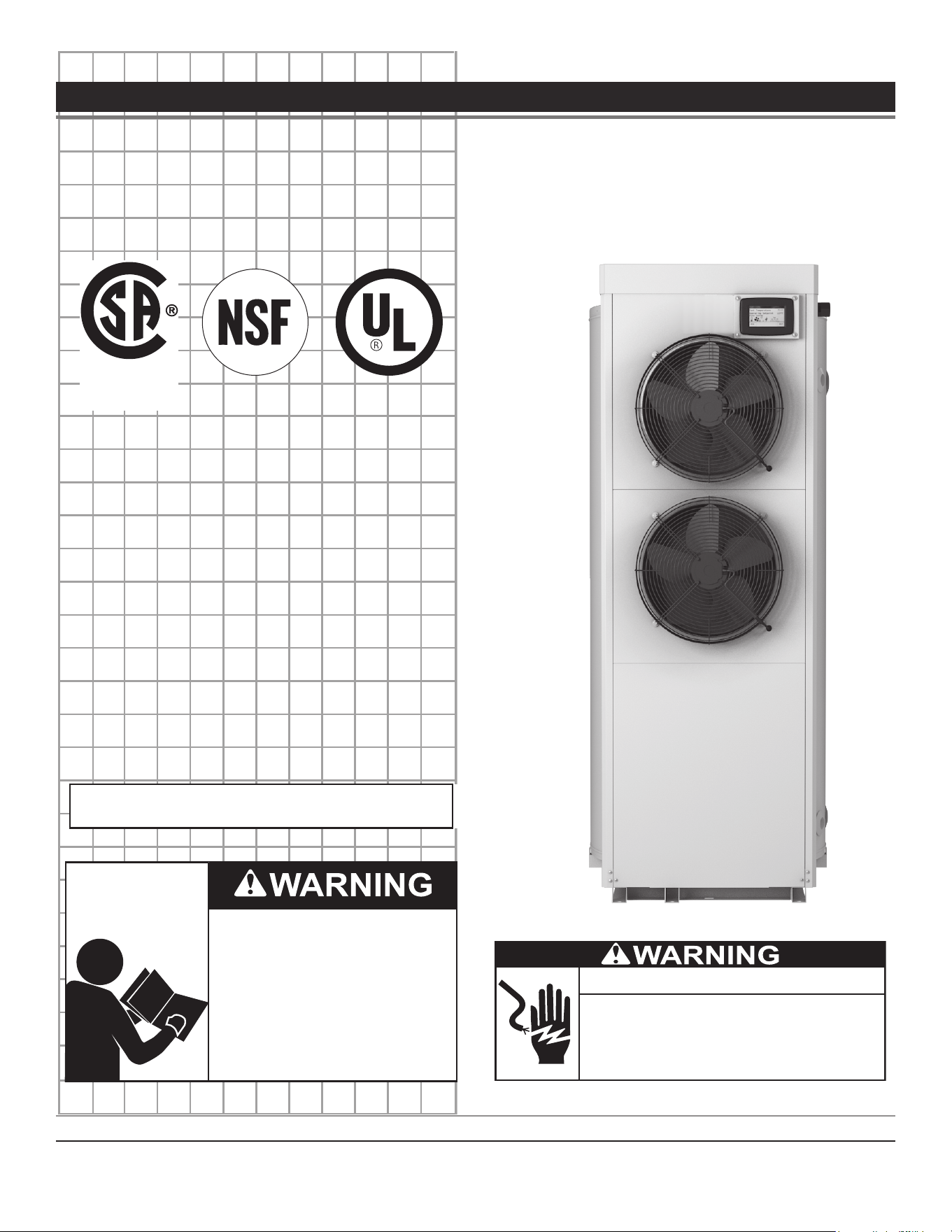
COMMERCIAL ELECTRIC HEAT PUMP WATER HEATER
LOW LEAD
CONTENT
®
Thank you for buying this energy efficient water heater. We
appreciate your condence in our products.
Read and understand this instruction
manual and the safety messages
herein before installing, operating or
servicing this water heater.
Failure to follow these instructions and
safety messages could result in death
or serious injury.
This manual must remain with the
water heater.
INSTALLATION - OPERATION
MAINTENANCE - SERVICE - TROUBLESHOOTING
If the water heater becomes immersed in water up to or
above the level of the bottom of the element doors,
the heater should be examined by a qualified service
agency before it is placed in operation.
Electrical Shock Hazard

2
CONTENTS
APPROVALS ................................................................................ 3
GENERAL SAFETY INFORMATION .......................................... 4
Do Not Use If Damaged ............................................................ 4
Hydrogen Gas (Flammable) ...................................................... 4
Hazard Messages ..................................................................... 5
Hazard Messages ..................................................................... 5
INTRODUCTION ......................................................................... 8
Preparing for the Installation ..................................................... 8
FEATURES AND COMPONENTS .............................................. 9
Components Left and Right Views .......................................... 10
INSTALLATION CONSIDERATIONS ....................................... 12
Rough-In Dimensions .............................................................. 12
Locating the Water Heater ...................................................... 12
Room Size Requirement ......................................................... 13
Service Clearances ................................................................. 14
Insulation Blankets .................................................................. 14
WATER HEATER INSTALLATION ............................................ 15
Required Ability ....................................................................... 15
General ................................................................................... 15
Thermostatic Point-of-Use Mixing Valves ............................... 15
Dish-washing Machines .......................................................... 16
Contaminated Water ............................................................... 16
Recirculating Loop .................................................................. 16
Hard Water .............................................................................. 16
Water Outlet Tube ................................................................... 16
Temperature-Pressure Relief Valve ........................................ 16
Closed Water Systems ............................................................ 17
Thermal Expansion ................................................................. 17
Condensate Drain Line Installation ......................................... 18
Electrical .................................................................................. 18
Branch Circuit .......................................................................... 18
Calculating Amperage/Over-current Protection ....................... 18
Electrical Connection Instructions ........................................... 19
STARTUP ................................................................................... 21
Filling the Water Heater ........................................................... 21
Initial Start Up .......................................................................... 21
Draining the Water Heater ....................................................... 21
DRY FIRE DETECTION CIRCUIT .......................................... 21
Defrost Cycle ........................................................................... 21
TEMPERATURE REGULATION ............................................... 22
High Temperature Limit Control (ECO) ................................... 22
Thermostat Control ................................................................. 22
High Temperature Applications ............................................... 23
SYSTEM OPERATION .............................................................. 24
Operating Modes ..................................................................... 24
Control System Navigation ...................................................... 24
MAINTENANCE ......................................................................... 33
Anode Rod Maintenance ......................................................... 33
Sediment Removal .................................................................. 34
Heating Element Replacement ............................................... 34
Temperature-Pressure Relief Valve Test ................................. 35
TROUBLESHOOTING .............................................................. 36
Checklist .................................................................................. 36
Fault and Alert Conditions ....................................................... 37
DIAGRAMS ................................................................................ 40
Wiring Diagrams ...................................................................... 40
Piping Diagram ........................................................................ 42
3
APPROVALS
All models are listed by Underwriters Laboratories Inc.
®
4 • Commercial Electric Heat Pump Water Heater
GENERAL SAFETY INFORMATION
DO NOT USE IF DAMAGED
DO NOT USE THIS WATER HEATER IF ANY PART HAS BEEN
EXPOSED TO FLOODING OR WATER DAMAGE.
Immediately
call a qualied service technician to inspect the water heater and to
replace any part of the control system which has been under water.
If the unit is exposed to the following, do not operate heater until all
corrective steps have been made by a qualied service technician.
1. External re.
2. Damage.
3. Firing without water.
Grounding Instructions
This water heater must be grounded in accordance with the National
Electrical Code and/or local codes. These must be followed in all
cases. Failure to ground this water heater properly may also cause
erratic control system operation on the
ELECTRONIC CONTROL
.
This water heater must be connected to a grounded metal,
permanent wiring system; or an equipment grounding conductor must
be run with the circuit conductors and connected to the equipment
grounding terminal or lead on the water heater.
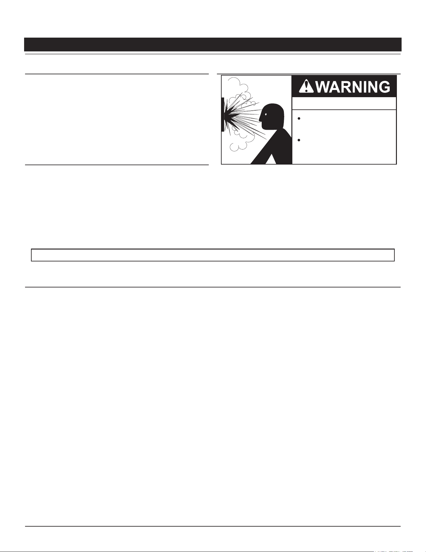
HYDROGEN GAS (FLAMMABLE)
Explosion Hazard
Flammable hydrogen gases
may be present.
Keep all ignition sources away
from faucet when turning on
hot water.
Hydrogen gas can be produced in a hot water system served by this
heater that has not been used for a long period of time (generally two
weeks or more). Hydrogen gas is extremely ammable. To reduce
the risk of injury under these conditions, it is recommended that the
hot water faucet be opened for several minutes at the kitchen sink
before using any electrical appliance connected to the hot water
system. If hydrogen is present there will probably be an unusual
sound such as air escaping through the pipe as the water begins
to ow.
THERE SHOULD BE NO SMOKING OR OPEN FLAME NEAR
THE FAUCET AT THE TIME IT IS OPEN.
Verify the power to the water heater is turned off before opening the control panel or performing any service procedures.
IMPORTANT DEFINITIONS
• Qualied Installer or Service Agency:
Installation and service of this water heater requires ability equivalent to that of a Qualied Agency (as dened by ANSI below) in the
eld involved. Installation skills such as plumbing, electrical supply are required in addition to electrical testing skills when performing
service.
• ANSI Z223.1 2006 Sec. 3.3.83:
“Qualied Agency” - “Any individual, rm, corporation or company that either in person or through a representative is engaged in and
is responsible for (a) the installation, testing or replacement of gas piping or (b) the connection, installation, testing, repair or servicing
of appliances and equipment; that is experienced in such work; that is familiar with all precautions required; and that has complied
with all the requirements of the authority having jurisdiction.”
General Safety Information
Commercial Electric Heat Pump Water Heater • 5
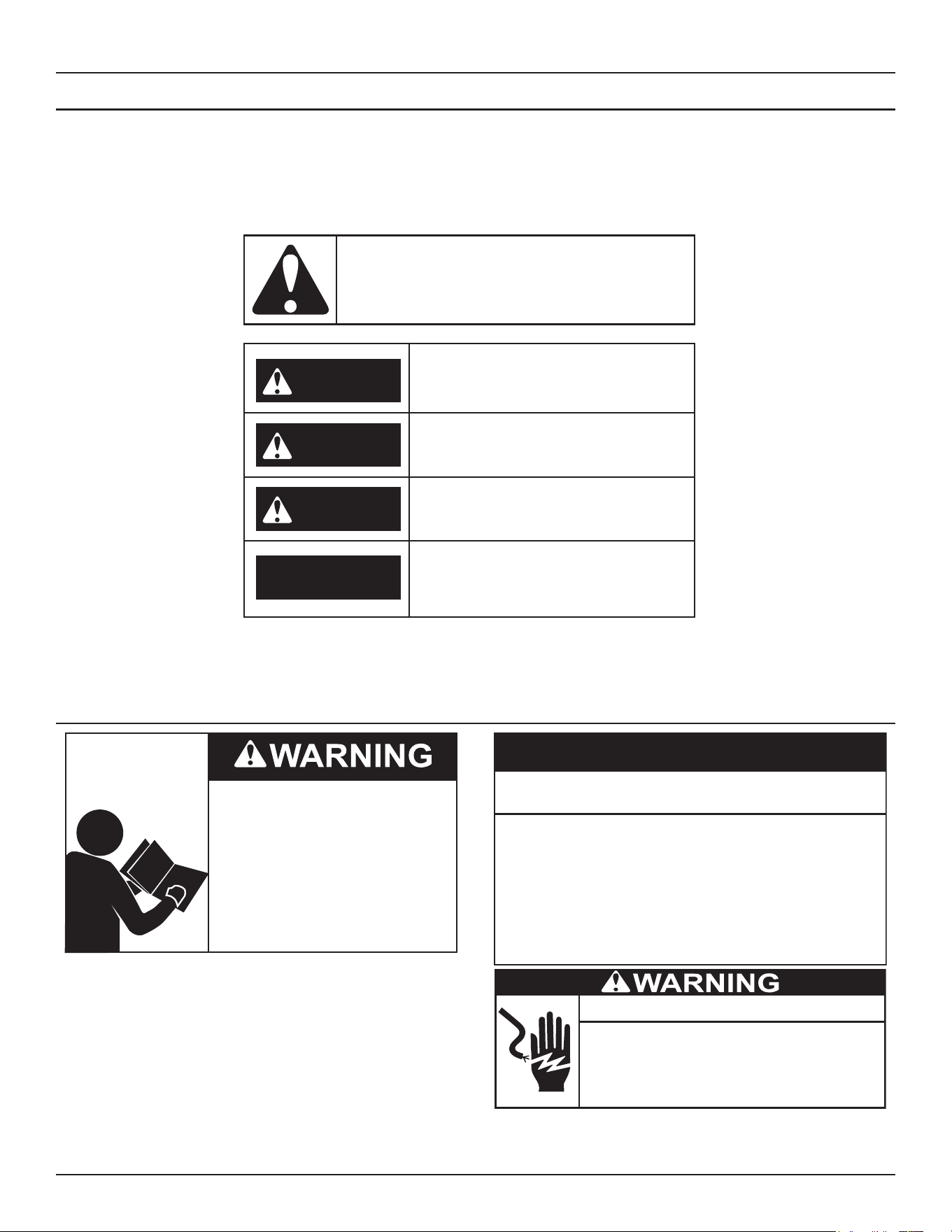
HAZARD MESSAGES
The proper installation, use and servicing of this water heater is
extremely important to your safety and the safety of others.
Many safety-related messages and instructions have been provided
in this manual and on your own water heater to warn you and others
of a potential injury hazard. Read and obey all safety messages
and instructions throughout this manual. It is very important that the
meaning of each safety message is understood by you and others
who install, use, or service this water heater.
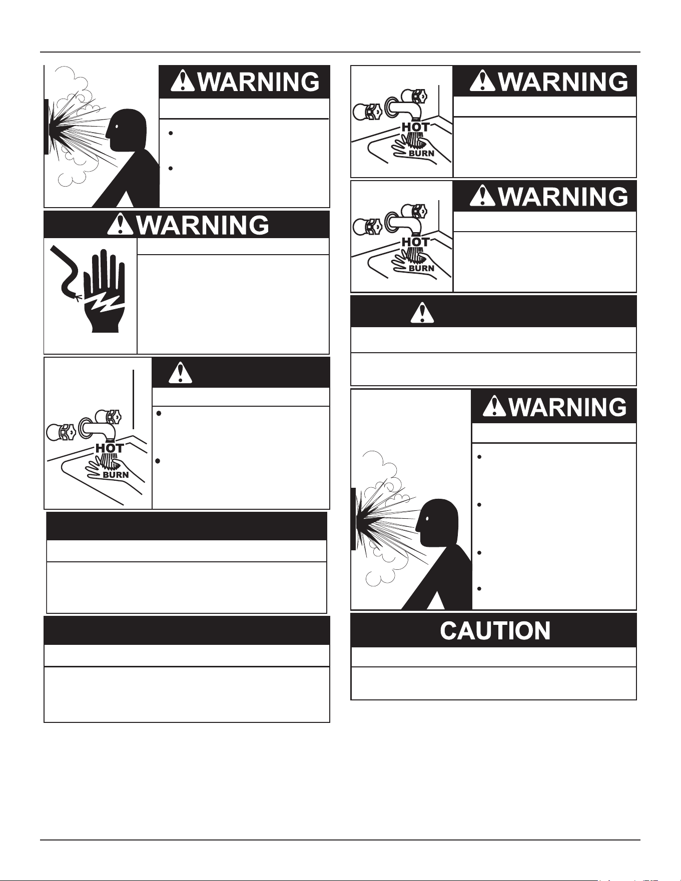
DANGER
WARNING
CAUTION
CAUTION
DANGER indicates an imminently
hazardous situation which, if not avoided,
will result in injury or death.
This is the safety alert symbol. It is used to alert you to
potential personal injury hazards. Obey all safety
messages that follow this symbol to avoid possible
injury or death.
WARNING indicates a potentially hazardous
situation which, if not avoided, could result
in injury or death.
CAUTION indicates a potentially hazardous
situation which, if not avoided, could result in
minor or moderate injury.
CAUTION used without the safety alert
symbol indicates a potentially hazardous
situation which, if not avoided, could result in
property damage.
All safety messages will generally tell you about the type of hazard, what can happen if you do not follow the safety message, and how
to avoid the risk of injury.
HAZARD MESSAGES
Read and understand this instruction
manual and the safety messages
herein before installing, operating or
servicing this water heater.
Failure to follow these instructions and
safety messages could result in death
or serious injury.
This manual must remain with the
water heater.
Improper installation, use and service may result
in property damage.
Do not operate water heater if exposed to flooding or
water damage.
•
Inspect anode rods regularly, replace if damaged.
•
Install in location with drainage.
•
Fill tank with water before operation.
•
Properly sized thermal expansion tanks are required on all
closed water systems.
•
Refer to this manual for installation and service.
CAUTION
If the water heater becomes immersed in water up to or
above the level of the bottom of the element doors,
the heater should be examined by a qualified service
agency before it is placed in operation.
Electrical Shock Hazard
6 • Commercial Electric Heat Pump Water Heater
General Safety Information
Explosion Hazard
Flammable hydrogen gases
may be present.
Keep all ignition sources away
from faucet when turning on
hot water.
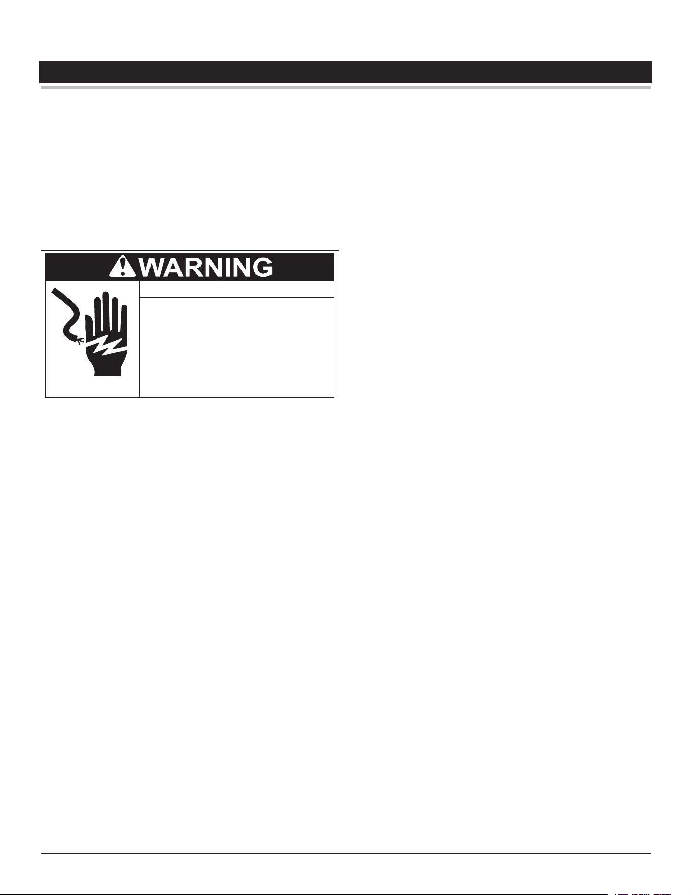
● Before removing any access panels or
servicing the water heater, make sure
the the electrical supply to the water
heater is turned OFF.
Electrical Shock Hazard
● Failure to follow these instructions can
result in personal injury or death.
Burn Hazard
WARNING
Do not connect the water heater to the power
supply, unless the tank has been completely
lled with water and a T&P valve has been
installed.
Water temperature over 125°F (52°C) can cause
severe burns instantly or death from scalds.
Children, the disabled and elderly are at
highest risk of being scalded. Feel water
temperature before bathing or showering.
Property Damage Hazard
•
All water heaters eventually leak.
•
Do not install without adequate drainage.
CAUTION
Property Damage Hazard
To avoid water heater damage, fill tank with water
before operating.
CAUTION
Burn Hazard
If you choose a higher temperature
setting, install thermostatic mixing
valves at each point-of-use to help
avoid scalding.
Burn Hazard
To reduce the risk of unusually hot
water reaching the fixtures in the
house, install thermostatic mixing
valves at each point of use.
Toxic Chemical Hazard
WARNING
● Do not connect to non-potable water system.
Explosion Hazard
Temperature-Pressure Relief Valve
must comply with ANSI Z21.22-
CSA 4.4 and ASME code.
Properly sized temperature-
pressure relief valve must be
installed in opening provided.
Can result in overheating and
excessive tank pressure.
Can cause serious injury or death.
Property Damage Hazard
● The temperature-pressure relief-valve discharge pipe
must terminate at an adequate drain.
General Safety Information
Commercial Electric Heat Pump Water Heater • 7
Burn Hazard
WARNING
Do not connect the water heater to the power
supply, unless the tank has been completely
lled with water and a T&P valve has been
installed.
Water temperature over 125°F (52°C) can cause
severe burns instantly or death from scalds.
Children, the disabled and elderly are at
highest risk of being scalded. Feel water
temperature before bathing or showering.
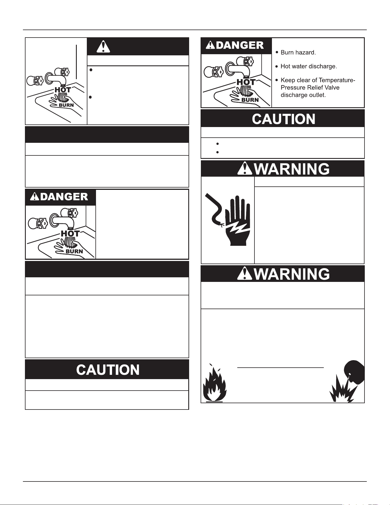
Property Damage Hazard
To avoid water heater damage, fill tank with water
before operating.
CAUTION
• Burn hazard.
• Hot water discharge.
• Keep hands clear of drain
valve discharge.
Improper installation, use and service may result
in property damage.
Do not operate water heater if exposed to flooding or
water damage.
•
Inspect anode rods regularly, replace if damaged.
•
Install in location with drainage.
•
Fill tank with water before operation.
•
Properly sized thermal expansion tanks are required on all
closed water systems.
•
Refer to this manual for installation and service.
CAUTION
Property Damage Hazard
● The temperature-pressure relief-valve discharge pipe
must terminate at an adequate drain.
Avoid damage.
Property Damage Hazard
Inspection and replacement of anode rod required.
Turn off power at the branch circuit
breaker serving the water heater
before performing any service.
Electrical Shock Hazard
•
Label all wires prior to disconnecting
when performing service. Wiring errors
can cause improper and dangerous
operation.
•
Verify proper operation after servicing.
•
Failure to follow these instructions can
result in personal injury or death.
•
Jumping out control circuits or components can
result in property damage, personal injury or death.
Service should only be performed by a qualified service
technician using proper test equipment.
•
Altering the water heater controls and/or wiring in any way
could result in permanent damage to the controls or water
heater and is not covered under the limited warranty.
•
Any bypass or alteration of the water
heater controls and/or wiring will result
in voiding the appliance warranty.
8 • Commercial Electric Heat Pump Water Heater
INTRODUCTION
Thank You for purchasing this water heater. Properly installed and
maintained, it should give you years of trouble free service.
Abbreviations Found In This Instruction Manual:
• ANSI - American National Standards Institute
• ASME - American Society of Mechanical Engineers
• NEC - National Electrical Code
• NFPA - National Fire Protection Association
• UL - Underwriters Laboratory
• CSA - Canadian Standards Association
PREPARING FOR THE INSTALLATION
● Before removing any access panels or
servicing the water heater, make sure
the the electrical supply to the water
heater is turned OFF.
Electrical Shock Hazard
● Failure to follow these instructions can
result in personal injury or death.
1. Read the “General Safety Information” section of this manual
rst and then the entire manual carefully. If you don’t follow the
safety rules, the water heater may not operate safely. It could
cause
DEATH, SERIOUS BODILY INJURY AND/OR PROPERTY
DAMAGE
.
This manual contains instructions for the installation, operation,
and maintenance of the heat pump water heater. It also contains
warnings throughout the manual that you must read and be
aware of. All warnings and all instructions are essential to the
proper operation of the water heater and your safety.
READ
THE ENTIRE MANUAL BEFORE ATTEMPTING TO INSTALL OR
OPERATE THE WATER HEATER.
Be sure to turn o power when working on or near the electrical
system of the heater. Never touch electrical components with
wet hands or when standing in water. When replacing fuses
always use the correct size for the circuit.
The model and rating plates interpret certain markings into useful
information. Both of these references should be used to identify
the heater, its components and optional equipment.
2. The installation must conform with these instructions and the
local code authority having jurisdiction and the requirements
of the power company. In the absence of local codes, the
installation must comply with the latest editions of the
National
Electrical Code, NFPA 70
or the
Canadian Electrical Code CSA C22.1
.
The
National Electrical Code
may be ordered from: National Fire
Protection Association, 1 Batterymarch Park, Quincy, MA 02269.
The Canadian Electrical Code is available from the Canadian
Standards Association, 8501 East Pleasant Valley Road,
Independence, OH 44131.
3. If after reading this manual you have any questions or do not
understand any portion of the instructions, call the toll free
number listed on the back cover of this manual for technical
assistance.
In order to expedite your request, please have full model and
serial number available for the technician.
4. Carefully plan your intended placement of the water heater.
Examine the location to ensure the water heater complies with
the “Locating the New Water Heater” section in this manual.
Installation and service of this water heater requires ability
equivalent to that of a licensed tradesman or qualied agency
in the eld involved. Plumbing and electrical work are required.
5. For installation in California, this water heater must be braced
or anchored to avoid falling or moving during an earth quake.
See instructions for correct installation procedures. Instructions
may be obtained from California Oce of the State Architect,
1102 Q Street Suite 5100, Sacramento, CA, 95811
6. Massachusetts Code requires this water heater to be installed
in accordance with Massachusetts 248-CMR 2.00: State
Plumbing Code and 248-CMR5. See Installing Carbon Monoxide
Detectors .
Important: The heat pump portion of this water heater uses
R-134a refrigerant. Any disposal of refrigerants shall
follow any state and local codes regarding refrigerants.
Commercial Electric Heat Pump Water Heater • 9
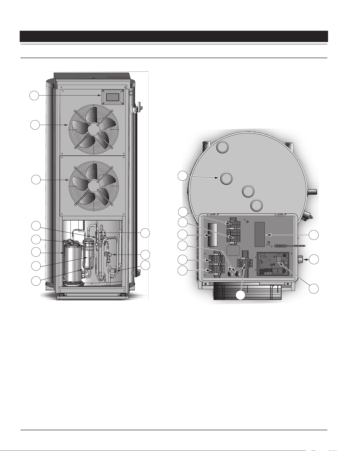
FEATURES AND COMPONENTS
COMPONENTS FRONT AND TOP
1
2
3
6
7
10
Lower panel removed for clarity.
5
4
8
9
11
22
12
15
17
18
21
Control panel removed for clarity.
19
16
20
14
13
Figure 1. Front and Top View
1. User Interface Module (UIM). The UIM includes the display circuit
board and control system’s LCD Touch Display. Used to adjust
various user settings and view operational information.
2. Upper Evaporator Fan
3. Lower Evaporator Fan
4. Suction Temperature Sensor (Located on Tubing)
5. Electronic Expansion Valve Coil (EEV)
6. Compressor
7. Accumulator
8. Discharge Temperature Sensor (located on tubing, not shown)
9. Refrigerant High Pressure Port
10. 4-Way Valve
11. Refrigerant Low Pressure Port
12. Anode. (Located beneath plastic cap)
13. Fuses and Extractor Type Fuse Holders for Compressor
14. Fuses and Extractor Type Fuse Holders for Upper and Lower
Elements.
15. Capacitor, Compressor
16. Capacitor, Upper/Lower Fans
17. Contactor, Upper Element
18. Contactor, Lower Element
19. Contactor, Compressor
20. Main Control Board (CCB)
21. Electrical Conduit Access Port
22. Terminal Block
10 • Commercial Electric Heat Pump Water Heater
Features and Components
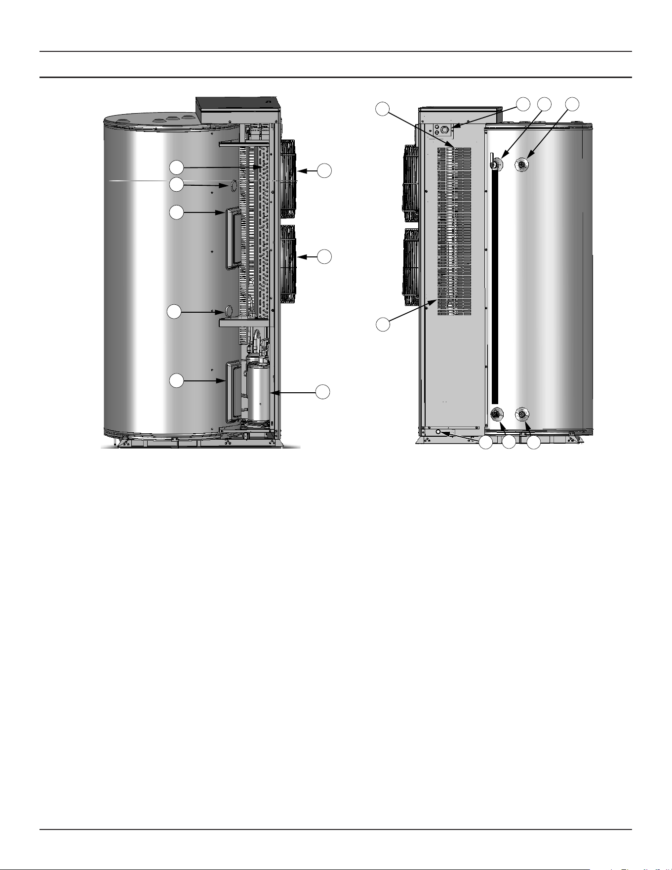
COMPONENTS LEFT AND RIGHT VIEWS
7
1
3
5
6
8
4
Side panel removed for clarity.
2
Left
Side
View
11 12 13
15
14
16
Right
Side
View
10
9
Figure 2. Left and Right Side Views
1. Evaporator
2. Upper Tank Temperature Sensor (located beneath plastic cap)
3. Upper Heating Element, ECO, Mid-Upper Tank Temperature
Sensor (Located behind panel).
4. Mid-Lower Tank Temperature Sensor (located beneath plastic
cap)
5. Lower Heating Element, ECO, Lower Tank Temperature Sensor
(Located behind panel).
6. Compressor
7. Lower Evaporator Fan
8. Upper Evaporator Fan
9. Coil Temperature Sensor (located behind side panel on
evaporator coil)
10. Ambient Air Sensor (Located behind side panel)
11. Electrical Conduit Access Port
12. Temperature-Pressure Relief Valve
13. Water Outlet Tube (3/4” NPT Connection)
14. Water Inlet (3/4” NPT Connection)
15. Drain Valve
16. Condensate Drain Tube (Not Shown). Exits from under panel.
Features and Components
Commercial Electric Heat Pump Water Heater • 11
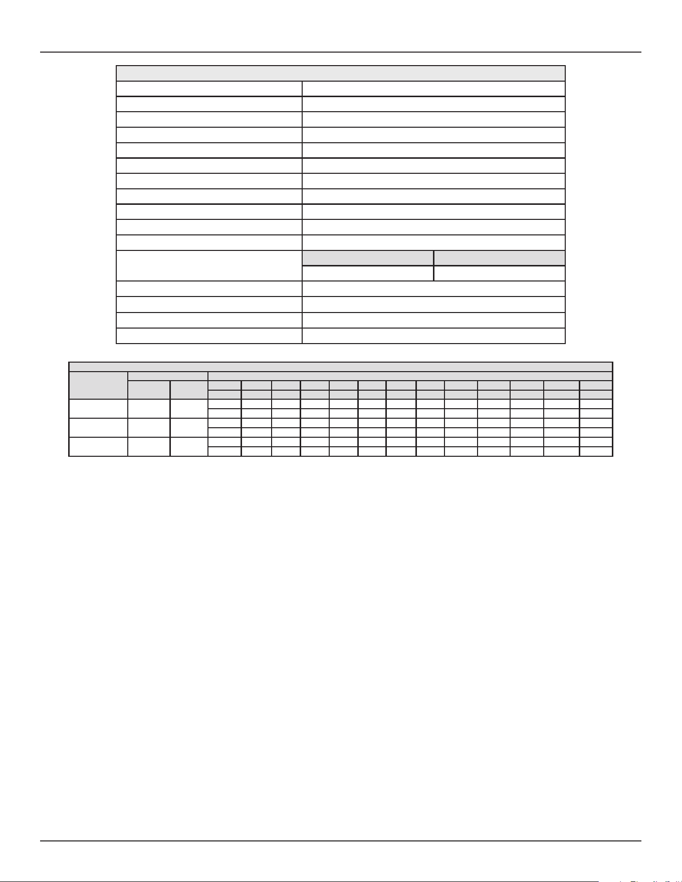
Table 1. Technical Characteristics
Model Type Integrated Heat Pump Water Heater
COP 4.2
HP Rated Input Power 3.15 HP (2.35 kW)
HP Rated Heating Output Capacity 11.13 kW
Power Specication 208/240Vac ~ 60Hz 1Ph
Maximum Operation Current 67 A
Refrigerant R134a
Refrigerant Charge Quantity 3.3 Lbs (1.5 Kg)
Electrical Heating Capacity 12.0 kW
Measured Tank Capacity 111.76 Gal (423 L)
Operation Modes Eciency, Hybrid, Electric
Max. Water Temperature
Eciency/Hybrid Electric
150°F (66°C) 180°F (82°C)
Operating Ambient Temperature 20 - 110°F (-6.6 - 43.3°C)
Unit Operation Noise 59 dB (A)
Approx. Heater Weight 498 Lbs (226 Kg)
Approx. Shipping Weight 620 Lbs (281 Kg)
Table 2. Recovery Rate In Gallons Per Hour
Mode of
Operation
Input Temperature Rise °F
Btu/hr kW
°F 30°F 40°F 50°F 60°F 70°F 80°F 90°F 100°F 110°F 120°F 130°F 140°F
°C 17°C 22°C 28°C 33°C 39°C 44°C 50°C 56°C 61°C 67°C 72°C 78°C
Eciency
33,678 9.87
GPH 136 102 82 68 58 51 45 41 37 34 31 29
LPH 515 386 309 258 221 193 172 155 140 129 119 110
Hybrid
74,624 21.87
GPH 302 226 181 151 129 113 101 90 82 75 70 65
LPH 1141 856 685 571 489 428 380 342 311 285 263 245
Electric
40,946 12
GPH 165 124 99 83 71 62 55 50 45 41 38 35
LPH 626 470 376 313 268 235 209 188 171 157 145 134
12 • Commercial Electric Heat Pump Water Heater
INSTALLATION CONSIDERATIONS
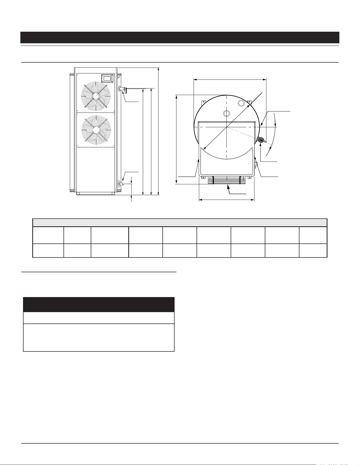
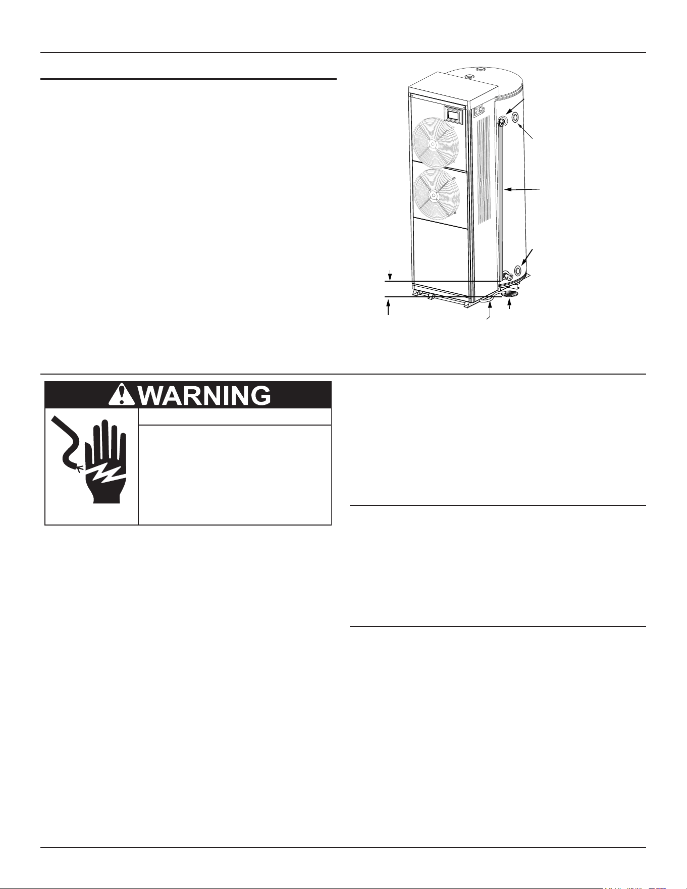
ROUGH-IN DIMENSIONS
G
F E A
Drain Valve
(3/4”NPT)
Relief Valve
(3/4” NPT)
α
ØB
Water
Connection
(3/4” NPT)
Relief Valve
Air Inlet
Air Outlet
D
Air Inlet
C
H
Figure 3. Rough-In Dimensions
Table 3. Physical Dimensions
Total
Height (A)
Tank
Diameter
(B)
Maximum
Depth (C)
Service Panel
Width (D)
Relief Valve
Height (E)
Water
Outlet Height
(F)
Water Inlet
Height (G)
Relief Valve
Angle α (°)
Maximum
Width (H)
69.68 in
(1770 mm)
28.03 in
(712 mm)
39.17 in.
(995 mm)
23.62 in.
(600 mm)
58.11 in.
(1476 mm)
57.80 in
(1468 mm)
6.02 in.
(153 mm) 22
30.91 in.
(785 mm)
LOCATING THE WATER HEATER
Carefully choose a location for the new water heater. The placement
is a very important consideration for the safety of the occupants in
the building and for the most economical use of the water heater.
Property Damage Hazard
•
All water heaters eventually leak.
•
Do not install without adequate drainage.
CAUTION
Whether replacing an existing water heater or installing the water
heater in a new location, observe the following critical points.
Important: The water heater must have unrestricted airow.
1. The water heater should be located indoors. If located outdoors,
it must be under a shelter or in an alcove where it will be
protected from the weather and other harsh elements.
2. The water heater must not be located in an area where it will
be subject to freezing temperatures.
3. Locate the water heater so that it is protected and not subject
to physical damage by a moving vehicle.
4. Locate the water heater on a level surface.
5. Locate the water heater near a oor drain. The water heater
should be located in an area where leakage of the tank or
connections will not result in damage to the area adjacent to
the water heater or to lower oors of the structure. When such
locations cannot be avoided, it is recommended that a metal
drain pan, adequately drained, be installed under the water
heater.
6. Locate the water heater close to the point of major hot water
usage.
7. Locate the water heater close to it’s electrical power supply.
8. Locate the water heater where an adequate supply of fresh air
for ventilation can be obtained.
The site location must be free from any corrosive elements in the
atmosphere such as sulfur, uorine, and chlorine. These elements
are found in aerosol sprays, detergents, bleaches, cleaning solvents,
air fresheners, paint, and varnish removers, refrigerants, and many
other commercial and household products. In addition, excessive
dust and lint may aect the operation of the unit.
Installation Considerations
Commercial Electric Heat Pump Water Heater • 13
The ambient air temperature must also be considered when installing
this unit. In Eciency Mode the ambient air temperature must be
above 45°F and below 109°F. If the ambient air temperature falls
outside these upper and lower limits the electrical elements will
activate to meet the hot water demand and the heat pump does
not operate.
The water heater should be located in an area where leakage of the
tank or connections will not result in damage to the area adjacent to
the heater or to lower oors of the structure.
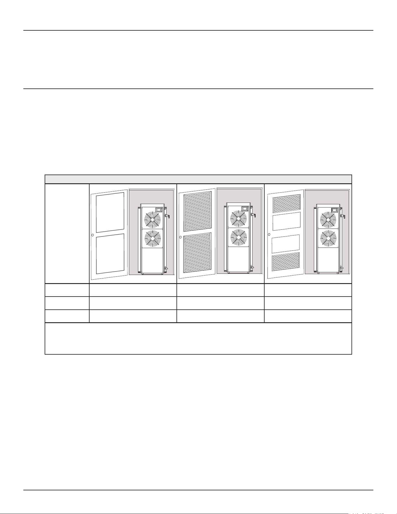
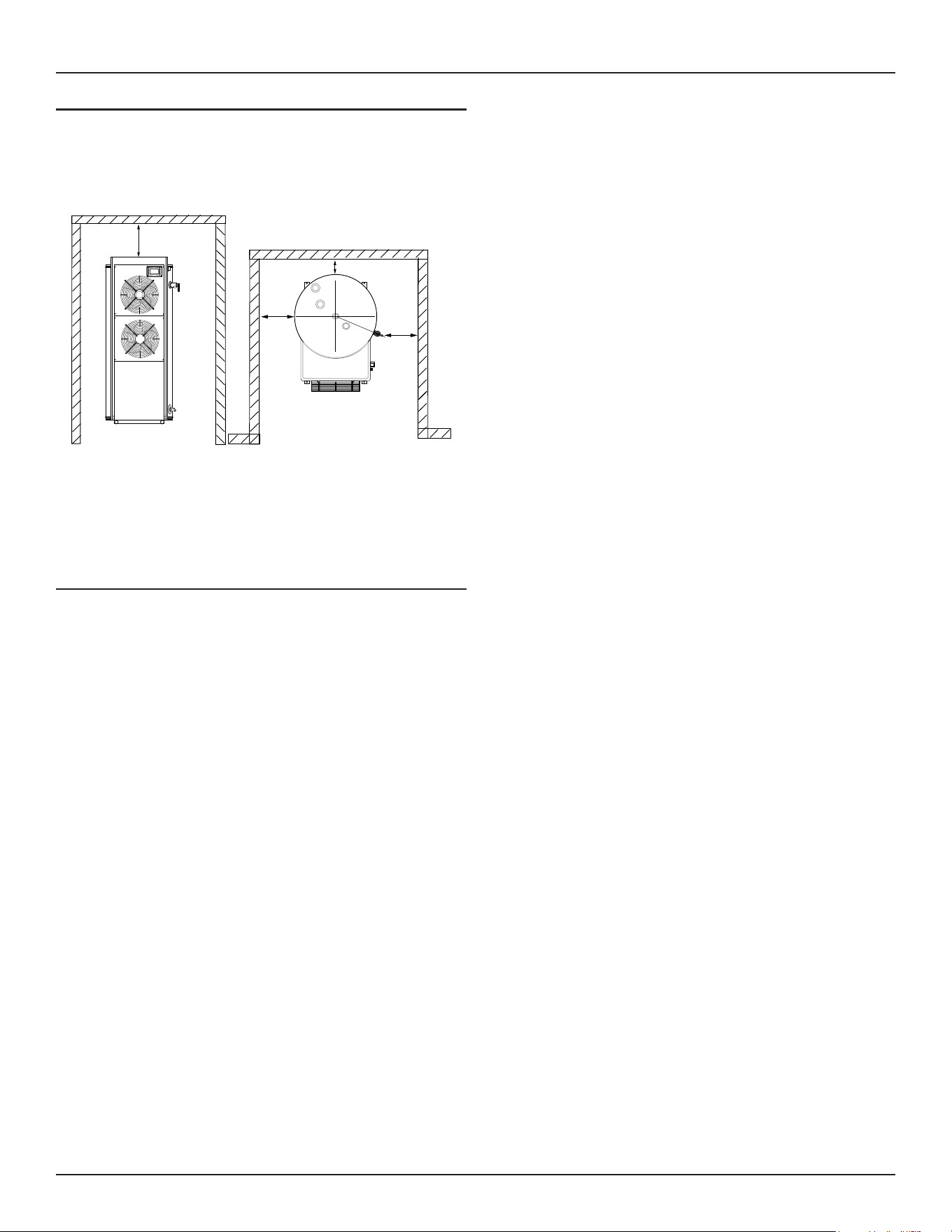
ROOM SIZE REQUIREMENT
The water heater should have adequate space (clearances)
for periodic servicing. For optimal water heater eciency and
performance, the water heater must have unrestricted airow and is
recommended to have a minimum installation space of approximately
3200 cubic feet. Installation spaces less than the recommended
could result in reduced water heater eciency and performance.
If the water heater is installed in a conned space with less than 3200
cubic feet, provisions should be made to ensure sucient airow,
such as installing louvered grills or fully louvered doors to ensure
the most ecient operation of the water heater. See
Table 4.
Failure
to do so could result in reduced heater eciency and performance.
If the ambient air temperature in the installed location drops more
than 15°F (8°C) during heating, air circulation is insucient and could
result in reduced water heater eciency and performance. The side
opposite to the fans should normally be left open with a minimum
clearance of 36” (91 cm) to any obstacles.
Table 4. Heat Pump Room Space Requirements
Conguration
(See Note 1) Enclosed Room (No louvers) Fully Louvered Door or Wall Opening Double Louvers in Wall or Door
Minimum Space
(FT
3
)
3200 1600 1600
Space Example
H x L x W (FT)
18 x 18 x 10 13 x 13 x 10 13 x 13 x 10
1. Total minimum louver open area is 4 ft
2
or 576 in
2
.
2. Installations less than the recommended room size could result in reduced water heater eciency and performance.
3. When two louvers are installed, install one louver at or near the top of the heater and the other one close to the bottom of the heater.
4. Maintaining a room temperature above 50°F(10°C) helps to avoid the defrost cycle being activated and provides for better heater eciency and
performance.
14 • Commercial Electric Heat Pump Water Heater
Installation Considerations
SERVICE CLEARANCES
A minimum clearance of 24” (61 cm) must be allowed for access to
replaceable parts such as thermostats, drain valve and relief valve.
Note: Adequate clearance for servicing should be maintained on
all installations.
24”
Top View
24”
6”
Alcove
24”
Front View
Figure 4. Clearances
A service clearance of 24 inches (61 cm) should be maintained from
serviceable parts such as the T&P valve, control system components,
drain valve, and anode. Leave as much space as possible above
the water heater for this reason.
INSULATION BLANKETS
The use of an insulation blanket on this water heater is not needed
or recommended. The purpose of an insulation blanket is to reduce
the standby heat loss encountered with storage tank heaters. Your
water heater meets or exceeds the National Appliance Energy
Conservation Act standards with respect to insulation and standby
loss requirements, making an insulation blanket unnecessary.
Commercial Electric Heat Pump Water Heater • 15
WATER HEATER INSTALLATION
REQUIRED ABILITY
Installation and service of this water heater requires ability equivalent
to that of a qualied installer or service agency in the eld involved.
Plumbing and electrical work is required.
GENERAL
The installation must conform with these instructions and the local
code authority having jurisdiction and the requirements of the power
company. In the absence of local codes, the installation must comply
with the latest editions of the National Electrical Code, NFPA 70 or
the Canadian Electrical Code CSA C22.1. The National Electrical
Code may be ordered from: National Fire Protection Association,
1 Batterymarch Park, Quincy, MA 02269. The Canadian Electrical
Code is available from the Canadian Standards Association, 8501
East Pleasant Valley Road, Independence, OH 44131.
Do NOT test electrical system before heater is lled with water, follow
the START UP procedure in the OPERATION section of this manual.
The principal components of the heater are identied in the
Features
and Components
illustrations (page 9).
Water temperature over 125°F (52°C)
can cause severe burns instantly
resulting in severe injury or death.
Children, the elderly and the
physically or mentally disabled are at
highest risk for scald injury.
Feel water before bathing or shower-
ing.
Temperature limiting devices such as
thermostatic point-of-use mixing
valves must be installed when
required by codes and to ensure safe
temperatures at fixtures.
Toxic Chemical Hazard
WARNING
● Do not connect to non-potable water system.
THERMOSTATIC POINT-OF-USE MIXING VALVES
Water heated to a temperature which will satisfy clothes washing, dish
washing, and other sanitizing needs can scald and cause permanent
injury upon contact. Short repeated heating cycles caused by small hot
water uses can cause temperatures at the point of use to exceed the
water heater’s temperature setting by up to 20°F (11°C).
Water temperature over 125°F (52°C)
can cause severe burns instantly
resulting in severe injury or death.
Children, the elderly and the
physically or mentally disabled are at
highest risk for scald injury.
Feel water before bathing or shower-
ing.
Temperature limiting devices such as
thermostatic point-of-use mixing
valves must be installed when
required by codes and to ensure safe
temperatures at fixtures.
Some people are more likely to be permanently injured by hot water
than others. These include the elderly, children, the inrm and the
physically/mentally disabled.
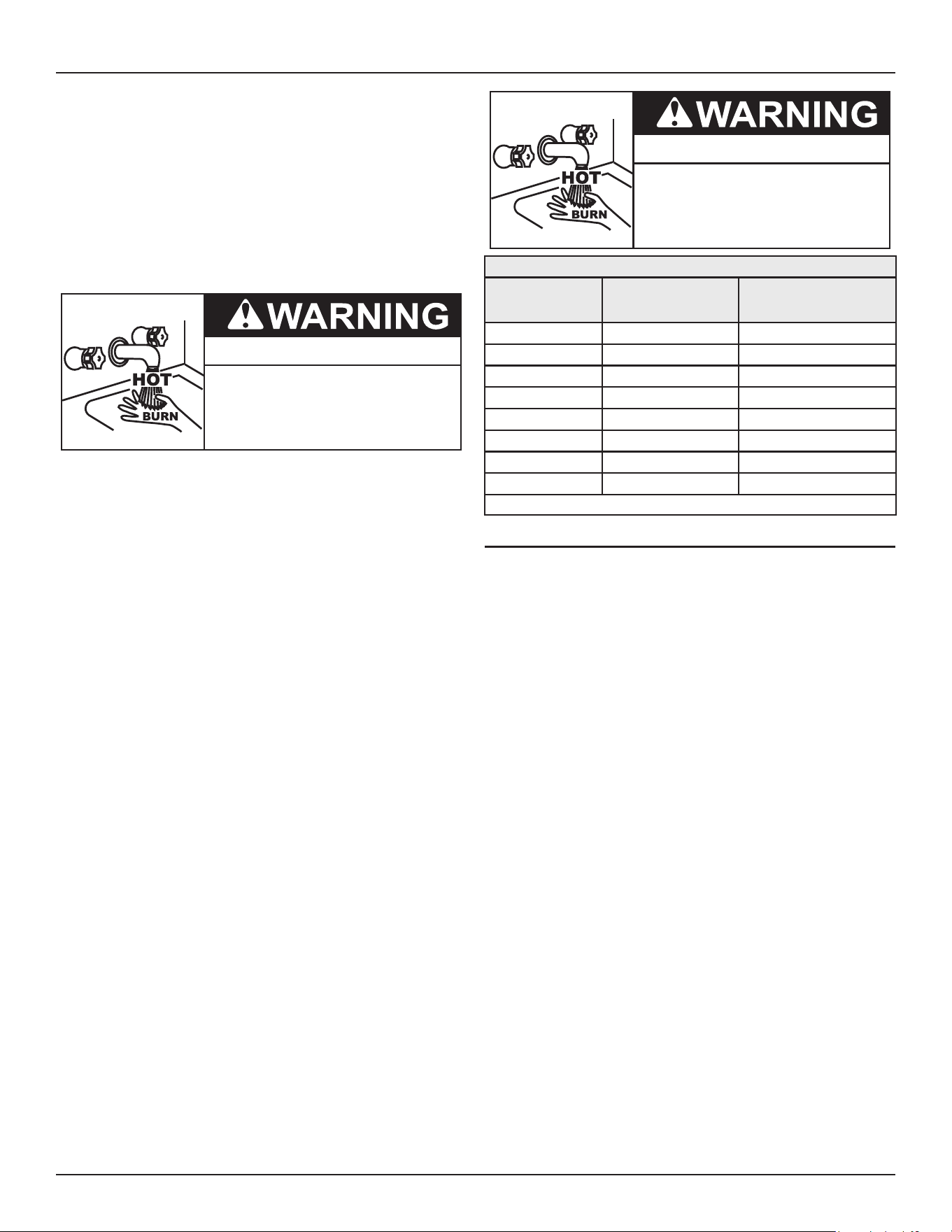
Table 5
shows the approximate time-to-burn
relationship for normal adult skin. If anyone using hot water provided by
the water heater being installed ts into one of these groups or if there
is a local code or state law requiring a certain water temperature at the
point of use, then special precautions must be taken.
Burn Hazard
If you choose a higher temperature
setting, install thermostatic mixing
valves at each point-of-use to help
avoid scalding.
In addition to using the lowest possible temperature setting
that satisfies the demand of the application a means, such as a
thermostatic point-of-use mixing valve, for example, can be used
at the hot water taps used by these people to reduce the water
temperature.
See
Figure 5
(page 16).
Check State and/or local codes for thermostatic point-of-use mixing
valve requirements and installation practices.
Mixing valves are available at plumbing supply stores. Consult a
Qualied Installer or Service Agency. Follow mixing valve manufacturer’s
instructions for installation of the valves.
Table 5. Burn Time at Various Temperatures
Water Temperature
°F (°C)
Time for 1st Degree
Burn
(Less Severe Burns)
Time for Permanent Burns
2nd & 3rd Degree
(Most Severe Burns)
110 (43) (normal shower temp.)
116 (47) (pain threshold)
116 (47) 35 minutes 45 minutes
122 (50) 1 minute 5 minutes
131 (55) 5 seconds 25 seconds
140 (60) 2 seconds 5 seconds
149 (65) 1 second 2 seconds
154 (68) instantaneous 1 second
(U.S. Government Memorandum, C.P.S.C., Peter L. Armstrong, Sept. 15, 1978)
16 • Commercial Electric Heat Pump Water Heater
Water Heater Installation
Burn Hazard
To reduce the risk of unusually hot
water reaching the fixtures in the
house, install thermostatic mixing
valves at each point of use.
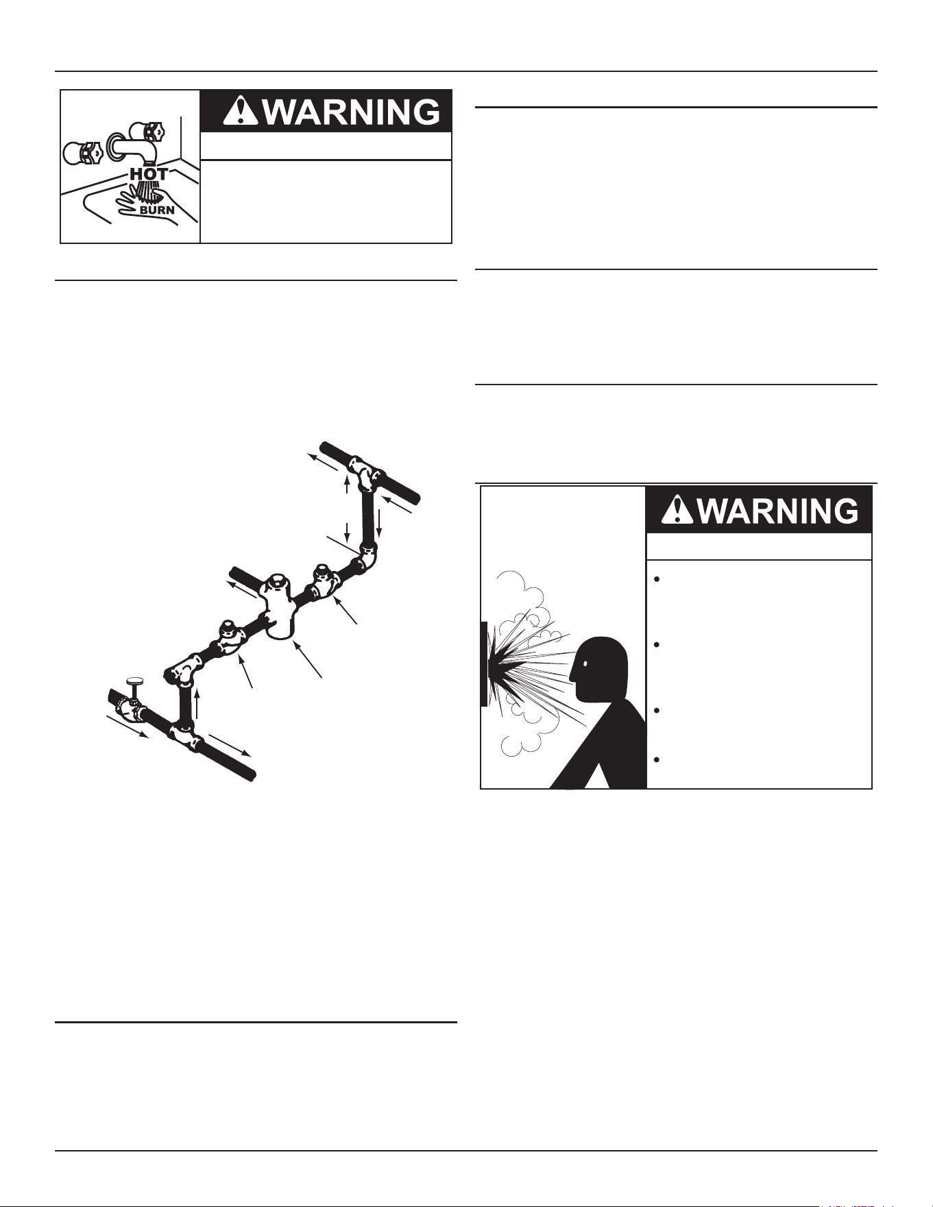
DISH-WASHING MACHINES
All dish-washing machines meeting the National Sanitation Foundation
requirements are designed to operate with water flow pressures
between 15 and 25 pounds per square inch (103 kPa and 173 kPa).
Flow pressures above 25 pounds per square inch (173 kPa), or below
15 pounds per square inch (103 kPa), will result in improperly sanitized
dishes. Where pressures are high, a water pressure reducing or ow
regulating control valve should be used in the 180°F (82°C) line to the
dish-washing machine and should be adjusted to deliver water pressure
between these limits.
HOT WATER
OUTLET
TO TANK
INLET
CHECK
VALVE
MIXING
VALVE
COLD
WATER
INLET
TEMPERED WATER
OUTLET
12” TO 15”
(30-38 cm)
CHECK
VALVE
Figure 5. Mixing Valve
The National Sanitation Foundation also recommends circulation of
180°F (82°C) water. The circulation should be just enough to provide
180°F (82°C) water at the point of take-o to the dish-washing machine.
Adjust ow by throttling a full port ball valve installed in the circulating
line on the outlet side of the pump. Never throttle ow on the suction
side of a pump. See the
Piping Diagram
(page 42).
Note: To comply with
NSF Standard 5
installation requirements, the
bottom of the water heater must be sealed to the oor with a
silicone based sealant or elevate
CONTAMINATED WATER
This water heater shall not be connected to any heating system(s)
or component(s) used with a non-potable water heating appliance.
Toxic chemicals, such as those used for boiler treatment shall not
be introduced into this system.
RECIRCULATING LOOP
The use of a recirculation loop is permitted with a maximum water
ow rate of 1.25 gpm. Higher water ow rates will result in reduced
water heater eciency and performance. Keep the water line runs as
short as possible to minimize heater operation run time and heat loss.
Refer to the circulating pump manufacturer’s instructions for its
operation, lubrication, and maintenance instructions.
HARD WATER
Where hard water conditions exist, water softening or the threshold
type of water treatment is recommended. This will protect the
dishwashers, coee urns, water heaters, water piping, and other
equipment.
WATER OUTLET TUBE
There is a tube installed in the water outlet connection of the water
heater. Take care not to move or damage it when installing the water
piping connections.
TEMPERATURE-PRESSURE RELIEF VALVE
Explosion Hazard
Temperature-Pressure Relief Valve
must comply with ANSI Z21.22-
CSA 4.4 and ASME code.
Properly sized temperature-
pressure relief valve must be
installed in opening provided.
Can result in overheating and
excessive tank pressure.
Can cause serious injury or death.
This water heater is provided with a properly rated/sized and certied
combination temperature-pressure relief valve (T&P valve) by the
manufacturer. The valve is certied by a nationally-recognized testing
laboratory that maintains periodic inspection of the production of
listed equipment and of materials as meeting the requirements for
Relief Valves for Hot Water Supply Systems, ANSI Z21.22
•
CSA 4.4
, and the
code requirements of
ASME
.
If replaced, the new T&P valve must meet the requirements of local
codes, but not less than a combination temperature-pressure relief
valve rated/sized and certied as indicated in the above paragraph.
The new valve must be marked with a maximum set pressure not to
exceed the marked hydrostatic working pressure of the water heater
(150 psi = 1,035 kPa) and a discharge capacity not less than the
water heater Btu/hr or kW input rate, as shown on the water heater’s
model rating label.
Note: In addition to the factory supplied temperature-pressure
relief valve on the water heater, each remote-storage tank
that is installed and piped to a water heating appliance
must also have its own properly-sized, rated, and approved
Water Heater Installation
Commercial Electric Heat Pump Water Heater • 17
temperature-pressure relief valve installed. Call the toll-free
technical-support phone number listed on the back cover of
this manual for technical assistance in sizing a temperature-
pressure relief valve for remote storage tanks.
For safe operation of the water heater, the temperature-pressure
relief valve must not be removed from its designated opening, nor
plugged. The temperature-pressure relief valve must be installed
directly into the tting of the water heater designed for the relief
valve. Install discharge piping so that any discharge exits the pipe
six inches (15.2 cm) above an adequate oor drain, or external to the
building. In cold climates, it is recommended that it be terminated at
an adequate drain inside the building. Be certain that no contact is
made with any live electrical part. The discharge opening must not
be blocked or reduced in size under any circumstances. Excessive
length over 30 feet (9.14 m) or use of more than four elbows can
cause restriction and reduce the discharge capacity of the valve.
No valve or other obstruction is to be placed between the temperature-
pressure relief valve and the tank. Do not connect discharge piping
directly to the drain unless an air gap of six inches (15.2 cm) is provided.
To prevent bodily injury, hazard to life, or property damage, the relief
valve must be allowed to discharge water in adequate quantities if
circumstances demand. If the discharge pipe is not connected to a drain
or other suitable means, the water ow could cause property damage.
Property Damage Hazard
● The temperature-pressure relief-valve discharge pipe
must terminate at an adequate drain.
T&P Valve Discharge Pipe Requirements:
• Shall not be smaller in size than the outlet-pipe size of the
valve, or have any reducing couplings or other restrictions.
• Shall not be plugged or blocked.
• Shall not be exposed to freezing temperatures.
• Shall be of material listed for hot water distribution.
• Shall be installed so as to allow complete drainage of both the
temperature-pressure relief valve and the discharge pipe.
• Must terminate a maximum of six inches (15.2 cm) above a
oor drain or external to the building. In cold climates, it is
recommended that the discharge pipe be terminated at an
adequate drain inside the building.
• Shall not have any valve or other obstruction between the
relief valve and the drain.
Water temperature over 125°F (52°C)
can cause severe burns instantly
resulting in severe injury or death.
Children, the elderly and the
physically or mentally disabled are at
highest risk for scald injury.
Feel water before bathing or shower-
ing.
Temperature limiting devices such as
thermostatic point-of-use mixing
valves must be installed when
required by codes and to ensure safe
temperatures at fixtures.
The temperature-pressure relief valve must be manually operated at
least twice a year. Caution should be taken to ensure that (1) no one is
in front of or around the outlet of the temperature-pressure relief valve
discharge line, and (2) the water that is manually discharged does not
cause any bodily injury or property damage because the water may be
extremely hot. If after manually operating the valve, it fails to completely
reset and continues to release water, immediately close the cold-water
inlet to the water heater, follow the draining instructions in this manual,
and replace the temperature-pressure relief valve with a properly rated/
sized new one.
Note: The purpose of a temperature-pressure relief valve is to
prevent excessive temperatures and pressures in the storage
tank. The T&P valve is not intended for the constant relief of
thermal expansion. A properly-sized thermal-expansion tank
must be installed on all closed systems to control thermal
expansion.
If you do not understand these instructions or have any questions
regarding the temperature-pressure relief valve, call the toll-free number
listed on the back cover of this manual for technical assistance.
CLOSED WATER SYSTEMS
Water supply systems may, because of code requirements or such
conditions as high line pressure, among others, have installed
devices such as pressure reducing valves, check valves, and back
ow preventers. Devices such as these cause the water system to
be a closed system.
THERMAL EXPANSION
As water is heated, it expands (thermal expansion). In a closed
system the volume of water will grow when it is heated. As the
volume of water grows there will be a corresponding increase in
water pressure due to thermal expansion. Thermal expansion can
cause premature tank failure (leakage). This type of failure is not
covered under the limited warranty. Thermal expansion can also
cause intermittent temperature-pressure relief valve operation:
water discharged from the valve due to excessive pressure build
up. This condition is not covered under the limited warranty. The
temperature-pressure relief valve is not intended for the constant
relief of thermal expansion.
A properly sized thermal expansion tank should be installed on all
closed systems to control the harmful eects of thermal expansion.
Contact a local plumbing service agency to have a thermal expansion
tank installed.
18 • Commercial Electric Heat Pump Water Heater
Water Heater Installation
CONDENSATE DRAIN LINE INSTALLATION
• Flexible PVC pipe or tubing must be used to connect the
condensate drain to a suitable drain.
• Condensate drain lines should be installed in conditioned
areas only.
• Do not connect condensate drain lines with other drain or
discharge lines into a single (common) pipe or line. Each line
(condensate drain line, temperature and relief valve discharge
pipe, etc.) should be independently run to an adequate drain.
• Slope the condensate drain lines toward the inside oor drain.
• The condensate drain lines and connections to the drain piping
must comply with all local codes.
6” Maximum
Air Gap
T&P Discharge Pipe
Drain
Cold
(Inlet)
Hot
(Outlet)
Temperature and
Pressure Relief Valve
Primary Condensate
Drain (3/4" Flex Tube)
Figure 6. Condensate Tube Installation
ELECTRICAL
● Before removing any access panels or
servicing the water heater, make sure
the the electrical supply to the water
heater is turned OFF.
Electrical Shock Hazard
● Failure to follow these instructions can
result in personal injury or death.
The installation must conform with these instructions and the local
code authority having jurisdiction and the requirements of the power
company. In the absence of local codes, the installation must comply
with the current editions of the
National Electrical Code, NFPA 70
or the
Canadian Electrical Code CSA C22.1
.
An electrical ground is required to reduce risk of electrical shock
or possible electrocution. The water heater should be connected
to a separate grounded branch circuit with over-current protection
and disconnect switch. The water heater should be grounded in
accordance with national and local codes.
Voltage applied to the heater should not vary more than +5% to -10%
of the model and rating plate marking for satisfactory operation.
DO NOT ENERGIZE THE BRANCH CIRCUIT FOR ANY REASON BEFORE THE
HEATER TANK IS FILLED WITH WATER. DOING SO WILL CAUSE THE HEATING
ELEMENTS TO BURN OUT AND VOID WARRANTY.
The factory wiring is attached to a terminal block within the internal
control unit. The branch circuit is connected to the terminal block
within this control box. The water heater should be connected to
a separate, grounded, branch circuit with over-current protection
and disconnect switch. The water heater should be grounded in
accordance with national and local codes.
BRANCH CIRCUIT
The branch circuit wire size should be established through reference
to the current edition of
NFPA-70
, the
National Electrical Code
or other
locally approved source in conjunction with the heater amperage
rating. For convenience, portions of the wire size tables from the
Code are reproduced in
Table 6
. The branch circuit should be sized
at 125 percent of the heater rating and further increase wire size as
necessary to compensate for voltage drop in long runs.
CALCULATING AMPERAGE/OVER-CURRENT PROTECTION
This water heater requires a 208 VAC 80-amp or 240 VAC 90-amp
single phase power supply, at 60 Hz.
The rating of the over-current protection should be computed on
the basis of 125 percent of the total connected load amperage.
Where the standard ratings and settings do not correspond with
this computation, the next higher standard rating or setting should
be selected.
Water Heater Installation
Commercial Electric Heat Pump Water Heater • 19
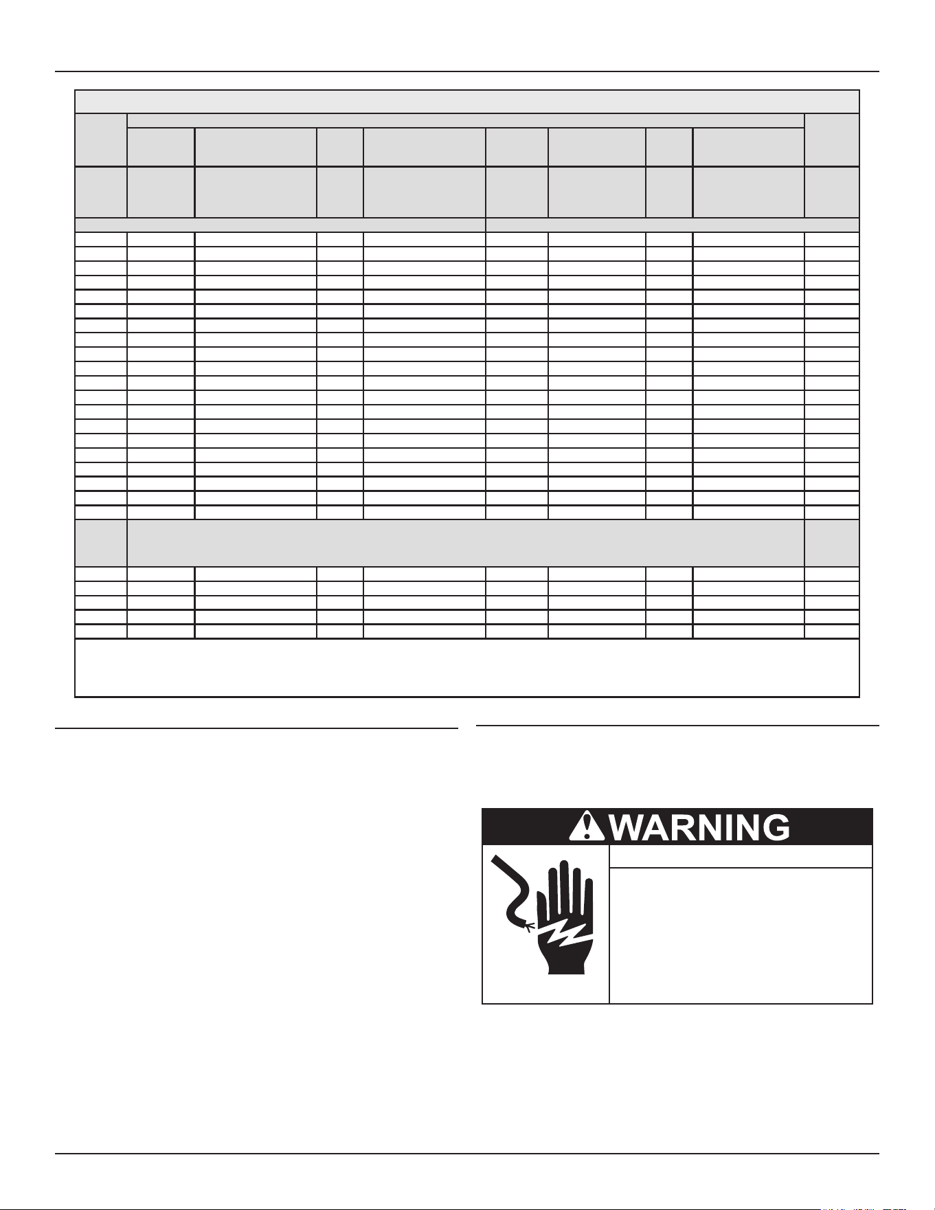
Table 6. Allowable Ampacities of Insulated Conductors
1
Size
Temperature Rating of Conductor
Size
60 °C
(140 °F)
75 °C
(167 °F)
85 °C
(185
°F)
90 °C
(194 °F)
60 °C
(140 °F)
75 °C
(167 °F)
85 °C
(185
°F)
90 °C
(194 °F)
AWG
MCM
Types
RUW,
TTW, and
UF
Types FEPW, RH,
RHW, RUH, THW,
THWN, XHHW, USE,
and ZW
Types
V, and
MI
Types TA, TBS, SA,
AVB, SIS, FEP
2
,
FEPB
2
, RHH
2
,
THHN
2
, and XHHW
2, 3
Types
RUW,
TTW, and
UF
Types RH, RHW,
RUH, THW,
THWN, XHHW,
and USE
Types
V, and
MI
Types TA, TBS,
SA, AVB, SIS,
RHH
2
, THHN
2
, and
XHHW
2, 3
AWG
MCM
Copper Aluminum or Copper-Clad Aluminum
18 .... .... .... 21 .... .... .... .... ....
16 .... .... 22 22 .... .... .... .... ....
14 15 15 25 25 .... .... .... .... ....
12 20 20 30 30 15 15 25 25 12
10 30 30 40 40 25 25 30 30 10
8 40 45 50 50 30 40 40 40 8
6 55 65 70 70 40 50 55 55 6
4 70 85 90 90 55 65 70 70 4
3 80 100 105 105 65 75 80 80 3
2 115 120 120 75 90 95 95 2
1 130 140 140 100 110 110 1
0 150 155 155 120 125 125 0
00 175 185 185 135 145 145 00
000 200 210 210 155 165 165 000
0000 230 235 235 180 185 185 0000
250 255 270 270 205 215 215 250
300 285 300 300 230 240 240 300
350 310 325 325 250 260 260 350
400 335 360 360 270 290 290 400
500 380 405 405 310 330 330 500
Ambient
Temp
°C
Correction Factors
For ambient temperatures over 30 °C, multiply the ampacities shown above by the appropriate correction factor to deter-
mine the maximum allowable load current.
Ambient
Temp °F
31-40 .82 .88 .90 .91 .82 .88 .90 .91 86-104
41-50 .58 .75 .80 .82 .58 .75 .80 .82 105-122
51-60 ...... .58 .67 .71 ...... .58 .67 .71 123-141
61-70 ...... .35 .52 .58 ...... .35 .52 .58 142-158
71-80 ...... ...... .30 .41 ...... ...... .30 .41 159-176
1. Not more than three conductors in raceway, cable, or earth (directly buried), based on ambient temperature of 30°C (86°F)
2. +The load current rating and the over-current protection for these conductors shall not exceed 15 amperes for 14 AWG. 20 amperes for 12 AWG and 30
amperes for 10 AWG copper; or 15 amperes for 12 AWG and 25 amperes for 10 AWG aluminum and copper-clad aluminum.
3. *For dry locations only. See 75°C column for wet locations.
ELECTRICAL CONNECTION INSTRUCTIONS
If you lack the necessary skills required to properly install the
electrical wiring to this water heater, do not proceed but have a
qualied electrician perform the installation.
When making the electrical connections, always make sure of the
following:
• The electrical service provides either 208 VAC or 240 VAC to
the water heater for proper operation.
• Wire sizes and connections comply with all applicable codes
or in the absence of local or state codes follow NFPA-70, the
National Electrical Code-current edition.
• Wiring enclosed in approved conduit (if required by local
codes).
• The water heater and electrical supply are properly grounded.
• The electrical supply has the proper overload fuse or breaker
protection.
Connecting the Water Heater to the Power Supply
Always reference the wiring diagram located on the water heater for
the correct electrical connections and connect the electrical supply
to the water heater in accordance with local utility requirements and
codes. See also
Wiring Diagrams
(page 40).
● Before removing any access panels or
servicing the water heater, make sure
the the electrical supply to the water
heater is turned OFF.
Electrical Shock Hazard
● Failure to follow these instructions can
result in personal injury or death.
When installing the electrical wiring to the water heater, do the
following:
1. Turn o power to the electrical wiring for the water heater at the
circuit breaker/fuse box.
2. Although this water heater is equipped with “Dry Fire” protection
circuitry, be sure tank is completely lled with water, and all air is
purged from the tank before making any electrical connections.
See
Draining the Water Heater
(page 21).
20 • Commercial Electric Heat Pump Water Heater
Water Heater Installation
3. Access the terminal block:
1) Unlatch the top control panel cover and pick up. See
Figure 1
(page 9) and
Figure 7
.
Note:
The top control panel cover is hinged and is not
removable.
2) Unscrew the power electrical conduit access port. See
Figure
1
(page 9) and
Figure 7
.
4. Run the main power through the power electrical conduit access
port. See
Figure 1
(page 9) and
Figure 7
.
Top Control Panel
Electrical Conduit
Access Port
Figure 7. Electrical Installation
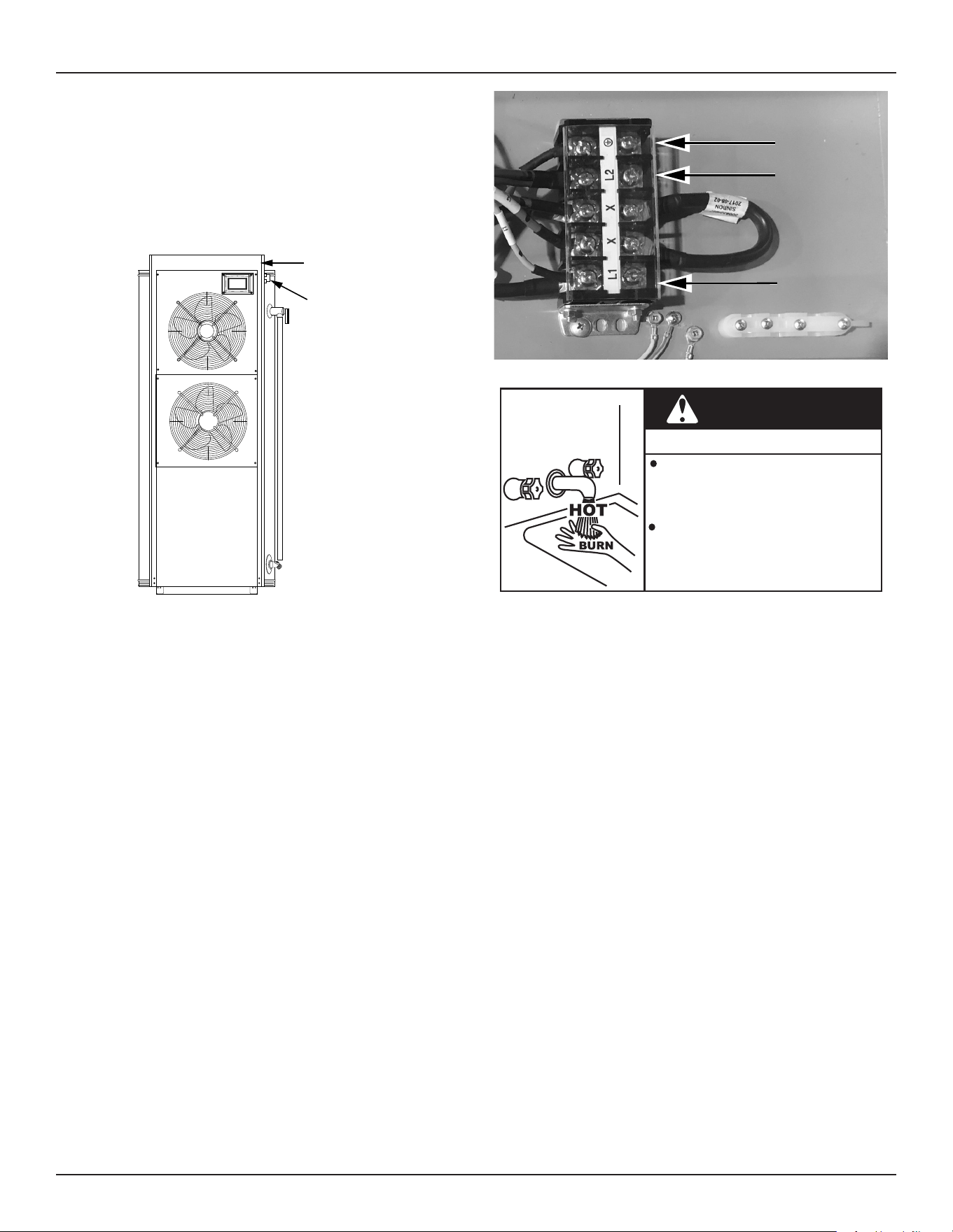
5. Connect incoming hot wires from the power supply to the terminal
block locations marked “L1” and “L2.” See
Figure 8
.
6. Connect the ground wire from the power supply to the terminal
marked with the ground symbol. See
Figure 8
.
Ground
L2
L1
Figure 8. Terminal Block
Burn Hazard
WARNING
Do not connect the water heater to the power
supply, unless the tank has been completely
lled with water and a T&P valve has been
installed.
Water temperature over 125°F (52°C) can cause
severe burns instantly or death from scalds.
Children, the disabled and elderly are at
highest risk of being scalded. Feel water
temperature before bathing or showering.
7. Replace and re-latch the top control panel cover and tighten the
Electrical Conduit Access connector.
Note:
Do not apply power to the water heater before
installation is complete and the water heater is lled
with water.
Commercial Electric Heat Pump Water Heater • 21
STARTUP
See
Features and Components
(page 9) for the location of
components mentioned in the instructions that follow.
NEVER turn on power to the water heater without being certain the
water heater is lled with water and a temperature and pressure
relief valve is installed in the relief valve opening.
DO NOT TEST ELECTRICAL SYSTEM BEFORE HEATER IS FILLED
WITH WATER. FOLLOW FILLING AND START-UP INSTRUCTIONS
IN OPERATION SECTION.
FILLING THE WATER HEATER
Property Damage Hazard
To avoid water heater damage, fill tank with water
before operating.
CAUTION
1. Turn o the electrical disconnect switch.
2. Close the water heater drain valve.
3. Open a nearby hot water faucet to permit the air in the system
to escape.
4. Fully open the cold water inlet pipe valve allowing the heater and
piping to be lled.
5. Close the hot water faucet as water starts to ow. The heater is
now ready for STARTUP and TEMPERATURE REGULATION.
INITIAL START UP
The following checks should be made by the installer when the heater
is placed into operation for the rst time.
1. Turn o the electrical disconnect switch.
2. Check all water and electrical connections for tightness. Also
check connections on top and or sides of heater. Repair water
leaks and tighten electrical connections as necessary.
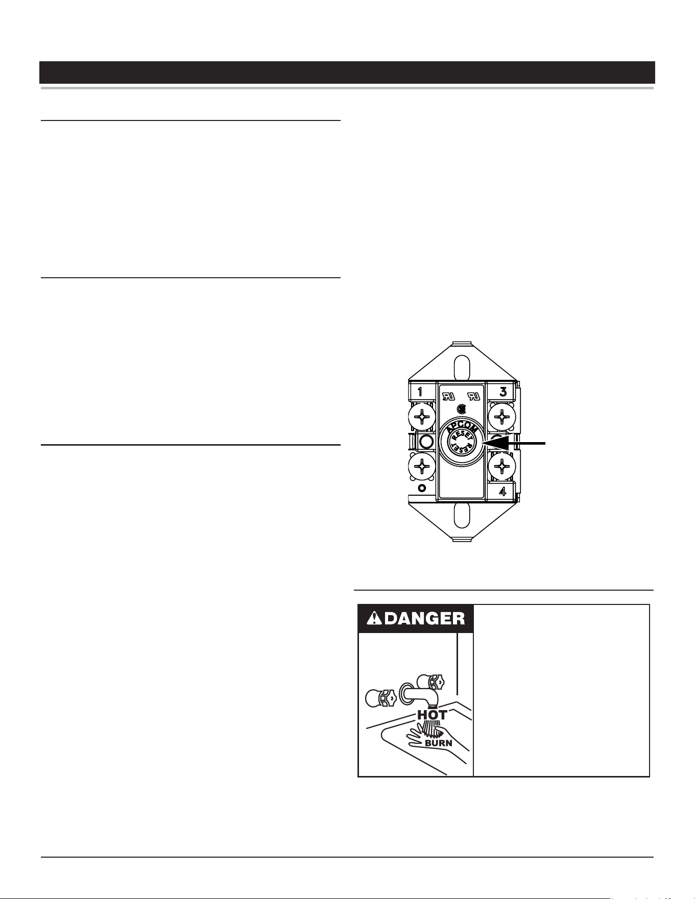
3. Depress the red manual reset button on each Thermostat/ECO
combination control.
4. Turn on the electrical disconnect switch.
5. Observe the operation of the electrical components during the rst
heating cycle. Use care as the electrical circuits are energized.
Temperature control and contactor operation should be checked by
allowing heater to come up to temperature and shut o automatically.
Use care as the electrical circuits are energized.
DRAINING THE WATER HEATER
The water heater must be drained if it is to be shut down and exposed
to freezing temperatures. Maintenance and service procedures may
also require draining the heater.
1. Turn o the electrical disconnect switch.
2. Open a hot water valve until the water is cool, then close the
supply water inlet valve to heater.
3. Attach hose to outlet opening of drain valve and direct end to
drain.
4. Open a nearby hot water faucet and the heater drain valve.
5. If the heater is being drained for an extended shutdown, it is
suggested the drain valve be left open during this period. The
hose may be removed.
Follow the instructions in
Filling the Water Heater
when restoring hot
water service.
• Burn hazard.
• Hot water discharge.
• Keep hands clear of drain
valve discharge.
DRY FIRE DETECTION CIRCUIT
The water heaters covered in this manual are equipped with a “Dry
Fire Detection” circuit to detect if the water level in the tank is higher
than the upper heating element. If the water level in the tank is
determined to be lower than the upper heating element the “Dry
Fire” fault will be enabled and all water heating will stop.
Whenever electrical power is removed and then restored to the water
heater the “Dry Fire Detection” circuit is automatically enabled and
lasts approximately 10-12 minutes.
Be sure tank is completely lled with water before applying electrical
power to the water heater.
DEFROST CYCLE
The water heaters covered in this manual are equipped with a defrost
cycle to remove frost and/or ice buildup on the evaporator coil.
Factors such as air temperature, humidity, air ow, and the condition
of the heat pump system inuence when and how often the system
will enter into a defrost cycle. Noticing steam around the front of the
water heater is a normal part of the defrost cycle as it is functioning
to melt the frost or ice accumulation on the evaporator coil.
Improper installation, use and service may result
in property damage.
Do not operate water heater if exposed to flooding or
water damage.
•
Inspect anode rods regularly, replace if damaged.
•
Install in location with drainage.
•
Fill tank with water before operation.
•
Properly sized thermal expansion tanks are required on all
closed water systems.
•
Refer to this manual for installation and service.
CAUTION
22 • Commercial Electric Heat Pump Water Heater
TEMPERATURE REGULATION
HIGH TEMPERATURE LIMIT CONTROL (ECO)
The water heaters covered by this manual are equipped with both an
Electronic Control and Surface Mount Control ECO (energy cut out)
non-adjustable high limit control. An ECO is a normally closed switch
that opens (activates) on a rise in temperature. If the ECO switch
contacts open (activate) due to abnormally high water temperatures
it will lock-out and disable further heating element operation. It is
important that a qualied service agent be contacted to determine
the reason for the ECO activation before resetting the ECO. Once
the reason has been determined and corrected the ECO(s) can be
reset as follows:
Electronic Control
The Electronic Control monitors the four tank temperature sensors.
The Electronic Control will disable all water heating when any one of
the four tank temperature sensors reach approximately 188°F/87°C
and will display a fault message. Voltage to the compressor and
element contactors is terminated to prevent further heating operation.
If the ECO activates, the water temperature must drop below the
water heater’s operating setpoint before the control system can be
reset. Once the water temperature has cooled below this point the
voltage to the compressor and element contactors is restored and
the control system will automatically be reset.
Surface Mount Control
There is a surface-mounted ECO control installed for each installed
heating element. The ECO high temperature limit switch contacts
on each control will open when the tank temperature reaches
approximately 200°F/93°C. When the upper element ECO switch
contacts open (activate), voltage to the main control board (CCB) and
user interface module (UIM) is terminated to prevent further heating
operation. Voltage will still be present to the water heater, however
the UIM on the front of the heater will be blank.
When the lower element ECO switch contacts open (activate) voltage
to the lower element only is terminated to prevent further heating
operation in the bottom of the tank. The upper element will continue
to operate to heat water.
The surface-mounted ECO is a manual reset switch. If one or more
ECOs activate, the tank temperature must drop below 140°F/60°C
and electrical power disconnected and restored before an ECO can
be reset. To manually reset an ECO, do the following:
1. Disconnect the power supply to the water heater.
2. Allow the tank temperature to cool below 140°F/60°C.
3. Remove the control cover from the eected control(s).
4. Press the manual reset button on each of the eected controls.
The water heaters covered in this manual are equipped with an
Electronic Control system to regulate water temperature inside the
storage tank. The control system monitors the temperature from four
factory-installed temperature sensors. See
Figure 2
(page 10) for
the location of the sensors.
The operating set point is adjusted to regulate water temperature inside
the storage tank. This is an adjustable user setting in the control system’s
Temperatures Menu. This and all control system menus are accessed
through the user interface module (UIM) located on the front of the water
heater. See
Figure 1
(page 9).
The water heaters covered by this manual have three modes of
operation. The Operating Set Point for each mode is adjustable:
• Eciency Mode: 95°F (35°C) to 150°F (65°C)
• Hybrid Mode: 95°F (35°C) to 150°F (65°C) (Factory Setting)
• Electric Mode: 95°F (35°C) to 180°F (82°C)
The factory setting is 120°F (49°C). See
Operating Set Point Adjustment
(page 27) for instructions on how to adjust the Operation Set Point
and other user settings.
Set the Operating Set Point at the lowest setting that produces an
acceptable hot water supply. This will always provide the most energy
ecient operation.
Reset
Button
Figure 9. ECO Switch and Reset Button
THERMOSTAT CONTROL
Water temperature over 125°F (52°C)
can cause severe burns instantly
resulting in severe injury or death.
Children, the elderly and the
physically or mentally disabled are at
highest risk for scald injury.
Feel water before bathing or shower-
ing.
Temperature limiting devices such as
thermostatic point-of-use mixing
valves must be installed when
required by codes and to ensure safe
temperatures at fixtures.
Temperature Regulation
Commercial Electric Heat Pump Water Heater • 23
Hot water temperatures required for automatic dishwasher and
laundry use can cause scald burns resulting in serious personal
injury and/or death.
Table 7
(page 23) shows the approximate
time-to-burn relationship for normal adult skin.
The temperature at which injury occurs varies with the person’s age
and duration of exposure. The slower response time of children,
the elderly or disabled persons increases the hazards to them. If
anyone using hot water provided by the water heater being installed
ts into one of these groups or if there is a local code or state law
requiring a certain water temperature at the point of use, then special
precautions must be taken.
Burn Hazard
If you choose a higher temperature
setting, install thermostatic mixing
valves at each point-of-use to help
avoid scalding.
In addition to using the lowest possible temperature setting
that satisfies the demand of the application, a means, such as a
thermostatic point-of-use mixing valve, for example, can be used
at the hot water taps used by these people to reduce the water
temperature.
See
Figure 5
(page 16).
Check State and/or local codes for thermostatic point-of-use mixing
valve requirements and installation practices.
Never allow small children to use a hot water tap or draw their own
bath water. Never leave a child or disabled person unattended in a
bathtub or shower.
The water heater should be located in an area where the general
public does not have access to set temperatures.
Setting the Operating Set Point at 120°F (49°C) will reduce the risk of
scalds. Some states require settings at specic lower temperatures.
Burn Hazard
To reduce the risk of unusually hot
water reaching the fixtures in the
house, install thermostatic mixing
valves at each point of use.
Table 7. Burn Time at Various Temperatures
Water Temperature
°F (°C)
Time for 1st Degree
Burn
(Less Severe Burns)
Time for Permanent Burns
2nd & 3rd Degree
(Most Severe Burns)
110 (43) (normal shower temp.)
116 (47) (pain threshold)
116 (47) 35 minutes 45 minutes
122 (50) 1 minute 5 minutes
131 (55) 5 seconds 25 seconds
140 (60) 2 seconds 5 seconds
149 (65) 1 second 2 seconds
154 (68) instantaneous 1 second
(U.S. Government Memorandum, C.P.S.C., Peter L. Armstrong, Sept. 15, 1978)
HIGH TEMPERATURE APPLICATIONS
Higher operating temperatures cause more wear on all water heaters
and will decrease the life span of the water heater. Consider installing
a small booster water heater for high temperature applications, such as
commercial dishwashers, to raise the outlet temperature from the larger
primary water heater to the desired point of use temperature.
Contact your local distributor or contact Technical Support for assistance.
See the contact information label on the water heater.
24 • Commercial Electric Heat Pump Water Heater
SYSTEM OPERATION
The water heaters covered in this manual are equipped with an Electronic
Control system that regulates water temperature inside the storage tank.
Heating cycles are managed by the control system. The ECO (energy cut
out), pressure switches, temperature sensors, compressor, contactors,
relays, and fans are monitored by the control system.
The main components of the control system are the user interface
module (UIM) and the main control board (CCB). The UIM is located
on the top front side of the water heater. The main control board (CCB)
is mounted on top of the water heater inside a protective enclosure.
OPERATING MODES
Hybrid Mode - This is the default, recommended setting. Combining
high energy eciency with reduced recovery time. This mode uses
the heat pump as the primary heating source. The heating elements
will heat water if demand exceeds a predetermined level so that the
setpoint temperature can be recovered more quickly.
Eciency Mode - Is the most energy ecient mode. This mode uses
the heat pump to heat water in the tank. The heating elements are
not used unless the ambient operating temperature is below 35°F or
above 109°F or if the hot water demand exceeds a predetermined
level so that the setpoint temperature can be recovered more
quickly. If hot water demands are not met in Eciency Mode it may
be necessary to switch to Hybrid Mode.
Electric Mode - The water heater functions as a conventional electric
unit, relying totally on the heating elements to heat the water in the
tank. This mode may be useful in winter to eliminate the output of
cold air from the unit.
CONTROL SYSTEM NAVIGATION
All operational information and user settings are displayed and accessed
from the user interface module (UIM). The UIM houses the control
system’s LCD Touch Display (liquid crystal display).
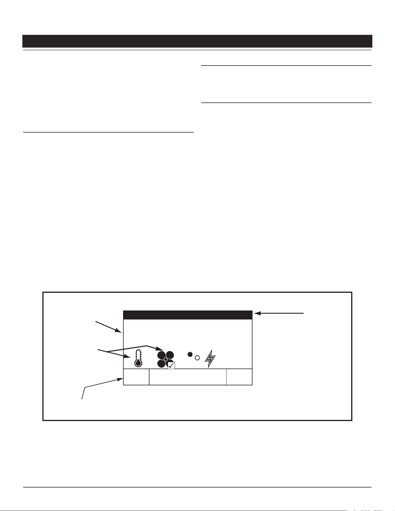
The Desktop Screen
During normal operation the control system will display the “Desktop”
screen on the LCD Touch Display which is the default screen. The
control system will return to the Desktop screen when there are no
active Fault or Alert conditions or when there has been no user input
for several minutes.
• Menu titles are displayed in the Title Bar when navigating the
control system menus.
• The rst temperature shown on the Desktop screen, Tank
Temperature, is the temperature of the water inside the water
heater’s storage tank.
• The second temperature shown on the Desktop screen
is the Operating Set Point. The Operating Set Point is the
temperature at which the control system will maintain the water
inside the storage tank.
• Beneath the Operating Set Point is the “Status” line. The
Status line shows the current operational state of the control
system in real time, see
Table 9
(page 26)
for a description of
the various operational states.
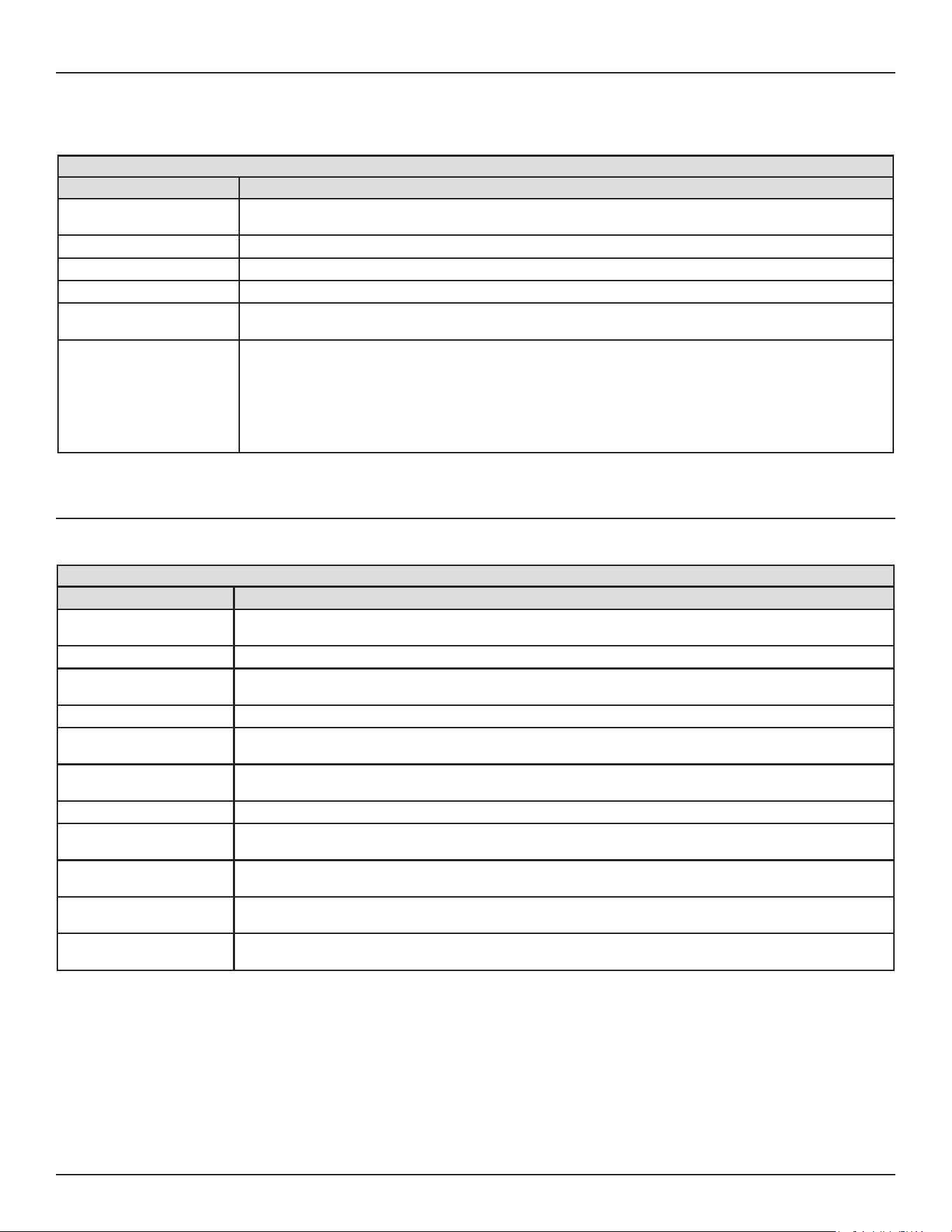
• The Desktop screen also displays animated “Status Icons”
to convey operational information, see
Table 8
(page 25)
for
descriptions of the Status Icons.
Tank Temperature 103°F
Operating Set Point 120°F
Status: Heating
HELPMENU
LCD Touch Display
Information
Display
Status Icons
Title Bar
Operational menus are multi functional.
Wednesday
12:00 PM
Efficiency
Figure 10. User Interface Module (UIM) Desktop Screen
System Operation
Commercial Electric Heat Pump Water Heater • 25
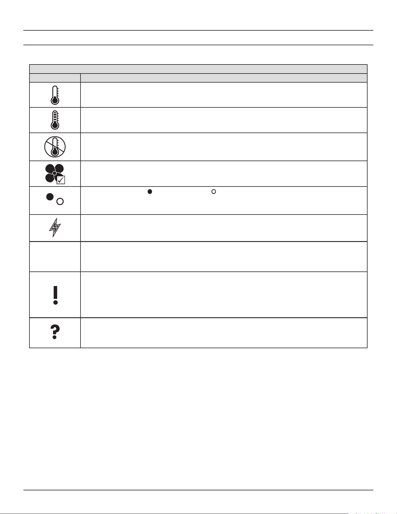
Status Icons
The Status Icons are displayed on the Desktop screen and convey operational and diagnostic information. The icons are described in the
table below.
Table 8. Status Icons
Icon Description
Water temperature in the tank has fallen. Shaded area of the animated thermometer icon will rise and fall
in response to water temperature in the storage tank as sensed from the upper and lower tank temperature
sensors.
Water temperature in the tank has reached the Operating Set Point. The control system enters the Standby
mode.
The control is unable to initiate a heating cycle. This will happen whenever a Fault condition is detected by
the control system. The display will read "Status: Water Heating Disabled."
The control is heating using the heat pump system.
Heating element status: = energized element, = element not energized,
There is a call for heat and/or the control system is in heating mode.
Wednesday
12:00 PM
Efficiency
Day of week, time of day, and current operation mode. “Clock Not Set” is displayed until the time/day is set.
The control system has declared a Fault condition and must be inspected/serviced by a Qualied Service
Agent. Fault message details can be viewed in the Current Fault menu. Heating operation is disabled (lock
out) until the condition that caused the Fault is corrected. Power to the water heater must be cycled o and
on at the breaker to reset the control system.
Note: Some faults are automatically reset by the control system and do not require recycling the power.
Note: Cycling power will not reset the control system if the condition that caused the fault has not been corrected.
The control system has declared an Alert condition and must be inspected/serviced by a Qualied Service
Agent. The water heater will continue to operate during an Alert condition.
26 • Commercial Electric Heat Pump Water Heater
System Operation
OPERATING STATES
The current operational state of the water heater is displayed on the Desktop screen as the “Status.” The common operational states are
described in the table below.
Table 9. Operating States
State Description
Standby The water heater is not in an active heating cycle. IE: the Tank Temperature is at or above the
Operating Set Point.
Water Heating Disabled A Fault condition is detected by the control.
Defrosting Frost has accumulated on the evaporator and the water heater control is performing a defrosting cycle.
Heating The control system is in Heating Mode.
Alert The control system has detected/declared an Alert Condition. The control system will continue heating
operation. However, a Qualied Service Agent should be contacted to check/service the water heater.
Fault The control system has detected a Fault condition. Heating operation is disabled until the Fault
condition is corrected. Power to the water heater must be cycled o and on at the breaker to reset the
control system.
Note: Some Faults are automatically reset by the control system and do not require recycling the power.
Note: Cycling power will not reset the control system if the condition that caused the Fault has not been
corrected.
Control System Menus
From the Desktop screen pressing “Menu” on the LCD Touch Display will display the “Main Menu” this is where all control system menus
are located. The table below describes the control system menus.
Table 10. Control System Menus
Menu Description
Temperatures Most commonly accessed menu. Contains the Operating Set Point, tank temperature, and compressor
temperatures.
Mode Displays and contains the operational modes of the water heater: Eciency, Electric, and Hybrid.
Heater Status This menu displays the current state of the elements, fans, and compressor. The on/o status of these
heater components are displayed in this menu.
Clock Contains the Current Time and Current Date user settings.
Display Settings Temperature units (°F or °C), the LCD appearance (brightness/contrast) and backlight delay user
adjustable settings are located in this menu.
Heater Information Total run time, Modes of Operation run times, Compressor Run Time, Fan Run Time, Element Run Time
along with UIM and CCB software revisions can be viewed in this menu.
Current Fault Displays any current Alert or Fault messages.
Fault History This control system menu retains a list of the last nine (9) Fault and Alert messages with a time stamp.
The newest event will replace the oldest. Faults will clear after 30 days.
Fault Occurrence This control system menu retains a running total of how many times each Fault condition has occurred
since the water heater was rst installed. The data does not clear and cannot be reset.
Restore Defaults This control system feature allows the user to restore control system user settings to their default
settings. Display Settings preferences ARE NOT changed when defaults are restored.
Help Screens Text based operational and user information explaining how to change user settings, navigate the control
system menus and icon descriptions.
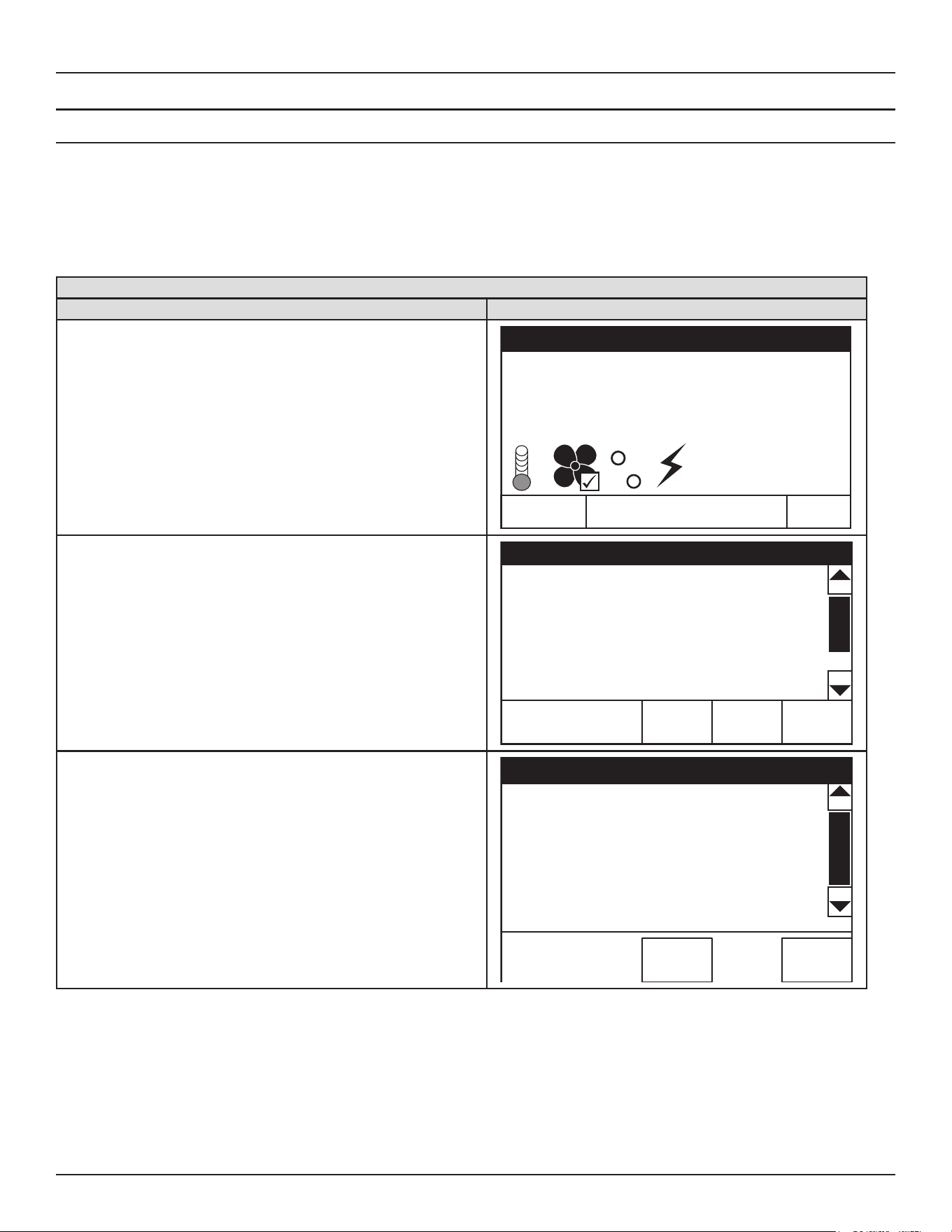
System Operation
Commercial Electric Heat Pump Water Heater • 27
USER SETTINGS & CONTROL SYSTEM MENUS
Temperatures Menu
Operating Set Point Adjustment
The Operating Set Point is adjustable from 95°F (35°C) to 150°F (65°C)
in Eciency and Hybrid models and 95°F (35°C) to 180°F (82°C) in
Electric mode. The factory setting is 120°F (49°C). These user settings
are accessed from the Temperatures menu. The following instructions
explain how to adjust these settings and navigate the control system
menus.
When the water temperature, sensed by the control system from the
tank temperature sensors, reaches the Operating Set Point, the control
system ends the heating cycle. A heating cycle is activated again when
the sensed water temperature drops below the Operating Set Point.
Temperatures Menu
Description/Action Display
From the Desktop screen, press MENU. The "Main Menu" screen will
be displayed.
Tank Temperature 103°F
Operating Set Point 120°F
Status: Heating
MENU HELP
Tue
07:24 AM
Efficiency
The Main Menu is where all control system menus are listed, see
Table 10
(page 26)
for a complete list and description of control system menus.
Use the Up and Down slidebar to view all control system menus from
the Main Menu.
Press "Temperatures" to access the Temperature menu.
Main Menu
HELPBACK
Temperatures
>
Mode >
Heater Status
>
Clock >
Display Settings
>
Press "Operating Setpoint" to access the temperature setpoint menu.
Note: Higher Temperature settings increase wear and operating
costs. Set the Operating Set Point to the lowest setting which
produces an acceptable hot water supply. This will always
provide the most energy ecient operation and longer life.
Temperatures
HELPBACK
Operating Setpoint 120°F >
Tank Temperature 81°F
Upper Temperature
82°F
Mid Upper Temperature
82°F
Lower Temperature
73°F
Mid Lower Temperature
79°F
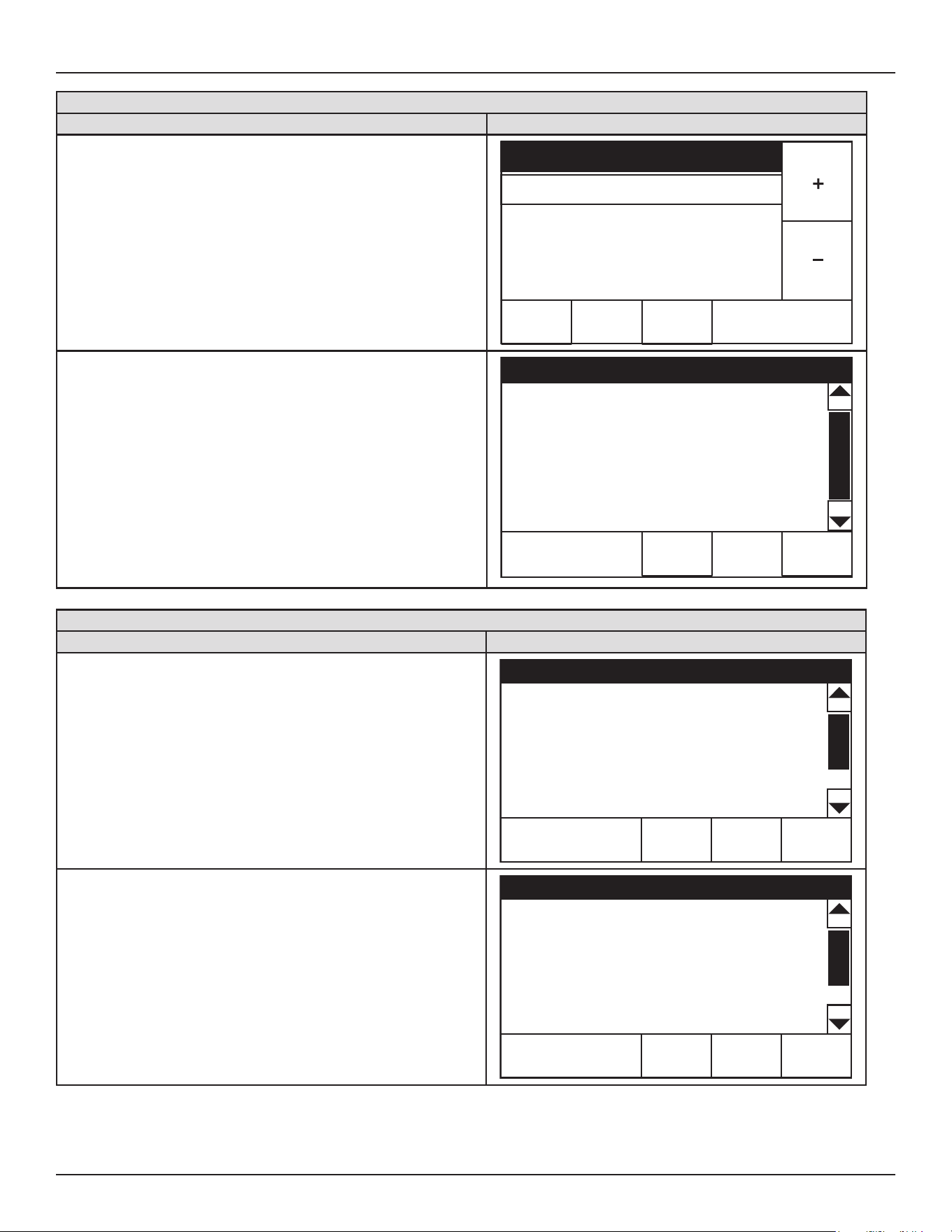
28 • Commercial Electric Heat Pump Water Heater
System Operation
Temperatures Menu
Description/Action Display
Use the "+" and "-" Buttons to change the current setting.
Press "ACCEPT" to save the new setting. Press "BACK" to discard
changes and return to the previously saved setting.
Note: Use this procedure to change the adjustable user settings in
the control system menus.
ACCEPT BACK
Operating Setpoint
MIN
95
°
F
MAX
150
°
F
120
°
F
• Tank Temperature - Non adjustable. Control system
sensed temperature (averaged from mid upper & mid-lower
temperature sensors).
• Upper Temperature - Non adjustable. Control system upper
temperature sensor sensed temperature.
• Mid-Upper Temperature - Non adjustable. Control system
mid-upper temperature sensor sensed temperature.
• Mid-Lower Temperature - Non adjustable. Control system
mid-lower temperature sensor sensed temperature.
• Lower Temperature - Non adjustable. Control system lower
temperature sensor sensed temperature.
Temperatures
HELPBACK
Operating Setpoint
120°F >
Tank Temperature
82°F
Upper Temperature
82°F
Mid Upper Temperature
82°F
Lower Temperature
73°F
Mid Lower Temperature
79°F
Mode of Operation Menu
Description/Action Display
Press Mode to access the Mode menu.
Main Menu
HELPBACK
Temperatures
>
Mode >
Heater Status
>
Clock >
Display Settings
>
Press > to activate the adjustment mode for this menu item.
Mode
HELPBACK
Mode Hybrid>
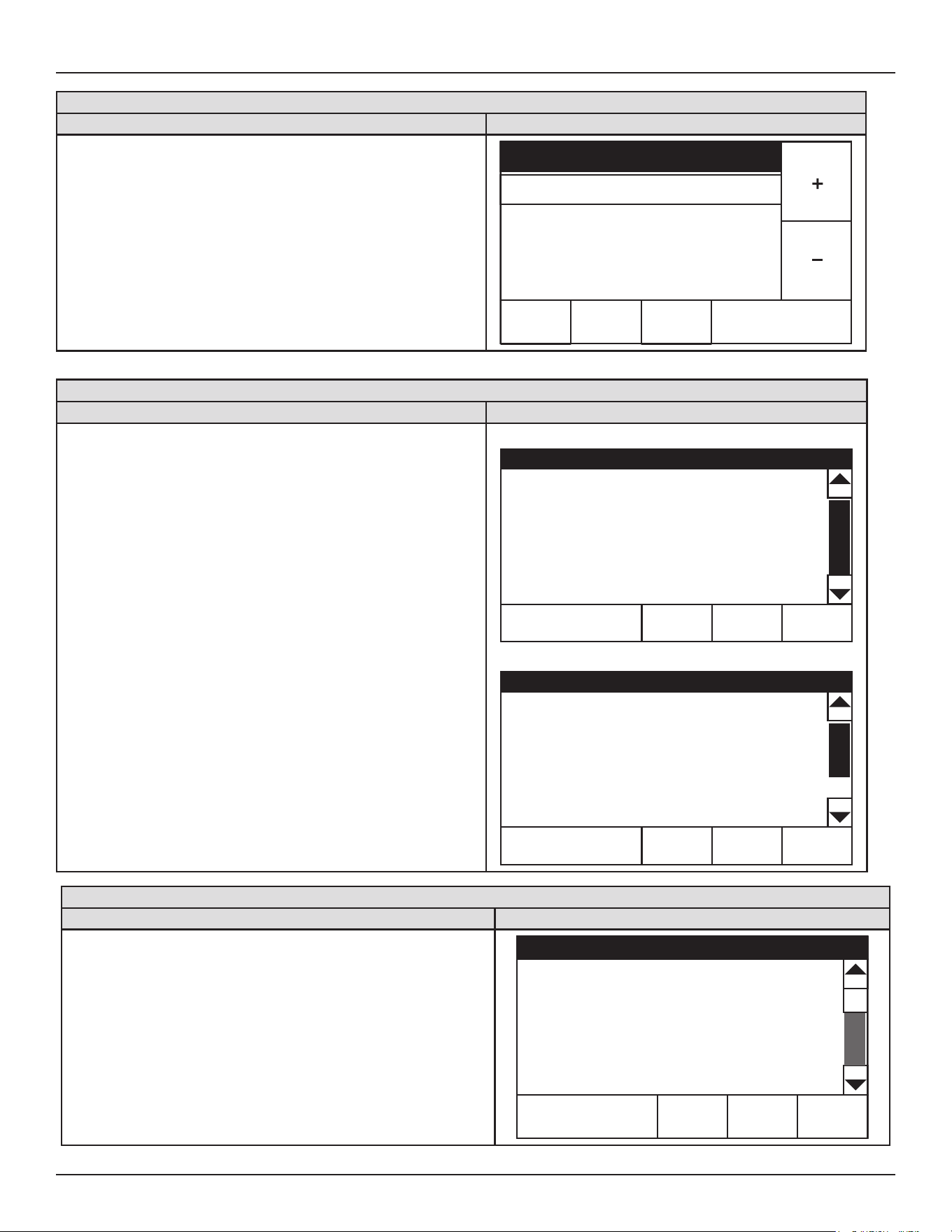
System Operation
Commercial Electric Heat Pump Water Heater • 29
Mode of Operation Menu
Description/Action Display
Use the “+” and “-” Buttons to change the current setting. There are 3
modes of operation, Eciency, Hybrid, and Electric. Hybrid mode is the
factory setting.
Press “ACCEPT” to save the new setting. Press “BACK” to discard
changes and return to the previously saved setting.
Note: Use this procedure to change the adjustable user settings in
the control system menus.
ACCEPT BACK
Mode
MIN
Efficiency
MAX
Hybrid
Hybrid
Heater Status Menu
Description/Action Display
Press Heater Status from the Main Menu to enter this menu. This menu
contains non adjustable operational information. Use the slidebar to
navigate the menu.
• Status - displays the current Operating State. See
Table 9
(page
26).
• Mode - Displays the current heater mode of operation.
• Upper/Lower Element, Fan, Compressor - displays whether
or not the control system is currently energizing these water
heater components: on = energized, o = de-energized.
• 4 Way Valve Status - Displays the status of the 4 Way Valve.
• EEV Steps - displays the pulses or signals sent by the CCB.
• Power Voltage - Displays the supply voltage.
Note: Menu displays shown are for informational purposes only. The
actual heater display will vary dependent upon the operational
state of the water heater.
Top of Menu
Heater Status
HELPBACK
Status: Standby
Mode Efficiency
Upper Element Off
Lower Element Off
Fan On
Compressor On
Bottom of Menu
Heater Status
HELPBACK
4 Way Valve Status Heating
EEV Steps 206 Pulses
Power Voltage 240 VAC
Blocked Inlet PS Closed
Blocked Outlet PS Closed
Compressor No
Clock Menu
Description/Action Display
Press Clock Settings from the Main Menu to enter this menu. This menu
contains adjustable display options for viewing information on the UIM’s
LCD screen. Use the Slidebar to navigate the menu.
• Current Date - Adjustable user setting that is used to set the
current date.
• Current Time - Adjustable user setting that is used to set the
current date.
Note: These settings are adjusted in the same way as described in
Operating Set Point Adjustment
(page 27).
Clock
HELPBACK
Current Date 01/01/2018 >
Current Time 12:00 AM >
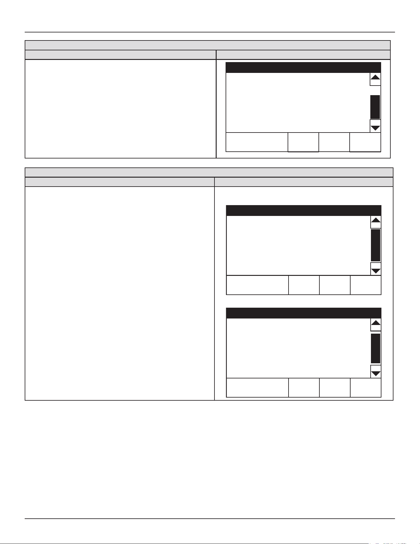
30 • Commercial Electric Heat Pump Water Heater
System Operation
Display Settings
Description/Action Display
Press Display Settings from the Main Menu to enter this menu. This menu
contains adjustable display options for viewing information on the UIM’s
LCD screen. Use the Slidebar to navigate the menu.
• Temperature Units - Adjustable user setting that changes
temperature units display to Celsius °C or Fahrenheit °F.
• Backlight Delay - Adjustable user setting that determines how
long the UIM’s LCD backlight remains illuminated after a key
has been pressed. Available settings are; Always O, 10, 30 or
60 seconds and Always On.
Note: These settings are adjusted in the same way as described in
Operating Set Point Adjustment
(page 27).
Display Settings
HELPBACK
Temperature Units °F >
Brightness 5 >
Backlight Delay 30s >
Heater Information
Description/Action Display
Press Heater Information from the Main Menu to enter this menu. This
menu contains non adjustable operational information.
• Total Run Time - Total accumulated time the control system
(water heater) has been energized.
• Eciency Mode Run Time - Total accumulated time the
control system has been in the Eciency mode of operation.
• Electric Mode Run Time - Total accumulated time the control
system has been in the Electric mode of operation.
• Hybrid Mode Run Time - Total accumulated time the control
system has been in the Hybrid mode of operation.
• Compressor Run Time - Total accumulated time the
compressor has been energized.
• Fan Run time - Total accumulated time the fans have been
energized.
• Upper Element Run Time - Total accumulated time the upper
element has been energized.
• Lower Element Run Time - Total accumulated time the lower
element has been energized.
• CCB Version - Software version for the main control board
(CCB).
•
UIM V
ersion
- Software version for the user interface module
(UIM). Version shown for reference only.
Top of Menu
Heater Information
HELPBACK
Total Run Time 22Hr
Efficiency Mode Run Time 3Hr
Electric Mode Run Time 0Hr
Hybrid Mode Run Time 17Hr
Compressor Run Time 11Hr
Fan Run Time 11Hr
Bottom of Menu
Heater Information
HELPBACK
Upper Element Run Time 0Hr
Lower Element Run Time 0Hr
CCB Version 1.03
UIM Version 4.10.00
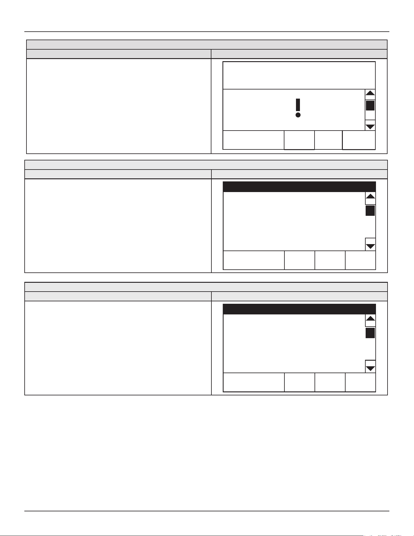
System Operation
Commercial Electric Heat Pump Water Heater • 31
Current Fault
Description/Action Display
Press Current Fault from the Main Menu to enter this menu. This menu
contains non adjustable operational information. Use the Slidebar to
navigate the menu.
This menu contains the current Fault or Alert error message. The time
the Fault or Alert message occurred appears directly below. A brief
description of what causes the particular Fault or Alert condition appears
below that. Pressing "ADVANCED" will give more detailed service
information and a list of possible causes for the Fault or Alert condition.
See
Fault and Alert Conditions
(page 37) for more detailed information
and diagnostic procedures.
If there is no Fault or Alert condition active this menu will not contain
any information, "(none)" will be shown next to Current Fault in the
Main menu.
ADVANCEDBACK
7/3/2018 02:58 PM
Error Code: 788-0
Mid-upper Sensor Fault
Fault History
Description/Action Display
Press "Fault History" from the Main Menu to enter this menu. This menu
contains non adjustable operational information. Use the Slidebar to
navigate the menu.
This menu contains a list of the last nine (9) Fault and Alert messages
with a time stamp. The newest event will replace the oldest. Faults will
clear after 30 days.
Press the Fault to view details for each Fault or Alert message stored.
Fault History
HELPBACK
1: Upper Element Fault (794) >
10/12/2017 10:10 AM
2: Mid-upper Sensor Fault (788) >
10/12/2017 10:10 AM
3: Mid-upper sensor Fault (788) >
10/12/2017 10:10 AM
Fault Occurrence
Description/Action Display
Press Fault Occurrence from the Main Menu to enter this menu. This
menu contains non adjustable operational information. Use the Slidebar
to navigate the menu.
This menu contains a running total of how many times each Fault condition
has occurred since the water heater was rst installed.
Fault Occurrence
HELPBACK
EEPROM Fault 0
Relay Error 0
Upper Sensor Fault 1
Mid-upper Sensor Fault 1
Mid-low Sensor Fault 1
Lower Sensor Fault 1
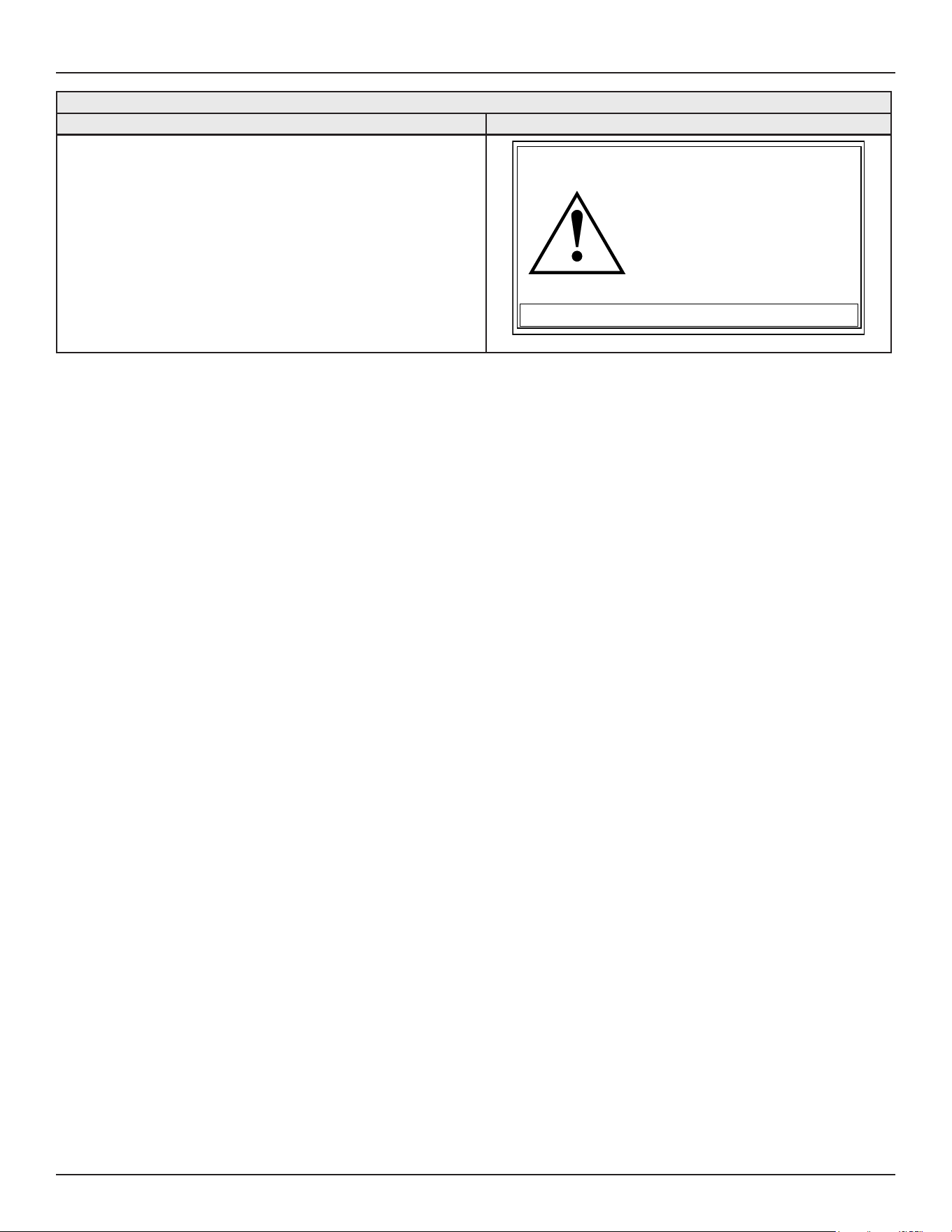
32 • Commercial Electric Heat Pump Water Heater
System Operation
Restore Defaults
Description/Action Display
Press Restore Defaults from the Main Menu to enter this menu.
To restore the adjustable user settings to their default settings press
“YES.” The display will show text conrming the default settings have
been restored.
Press NO to exit the Restore Defaults menu.
NO
YES
Restore Defaults
Are you sure you want to
restore the system to defaults?
Commercial Electric Heat Pump Water Heater • 33
MAINTENANCE
Table 11. Maintenance Schedule
Component Operation Interval Reference
Tank Drain and Flush
Every 6
Months
See
Draining the Water
Heater
(page 21) and
Flushing the Water Heater
Storage Tank
(page 33).
Tank
Lime Scale Re-
moval
(Water Less Than
25 Grains Hard)
Not Required N/A
Tank
Lime Scale Re-
moval
(Water Greater
Than 25 Grains
Hard)
Annually
See
Sediment Removal
(page
34).
Moving Parts Lubrication Not Required N/A
Anodes
Inspection
/Cleaning
Annually See
Anode Rod Maintenance.
T&P Valve Test Operation Semi Annually
See
Temperature-Pressure Re-
lief Valve Test
(page 35).
Property Damage Hazard
● The temperature-pressure relief-valve discharge pipe
must terminate at an adequate drain.
Periodically the drain valve should be opened and the water allowed
to run until it ows clean. This will help to prevent sediment buildup
in the tank bottom.
Periodically check the temperature and pressure relief valve to
ensure that it is in operating condition. Lift the lever at the top of the
valve several times until the valve seats properly and operates freely.
Water heater maintenance includes periodic tank ushing and
cleaning, and removal of lime scale from the heating element.
ANODE ROD MAINTENANCE
The heater tank is equipped with an anode rod to aid in corrosion
control.
Avoid damage.
Property Damage Hazard
Inspection and replacement of anode rod required.
The anode rod is used to protect the tank from corrosion. Most hot-water
tanks are equipped with an anode rod. The submerged rod sacrices
itself to protect the tank. Instead of corroding the tank, water ions attack
and eat away the anode rod. This does not aect water’s taste or color.
The rod must be maintained to keep the tank in operating condition.
Anode deterioration depends on water conductivity, not necessarily
water condition. A corroded or pitted anode rod indicates high water
conductivity and should be checked and/or replaced more often than
an anode rod that appears to be intact. Replacement of a depleted
anode rod can extend the life of your water heater. Inspection should
be conducted by a qualied service agency.
Articially-softened water is exceedingly corrosive because the process
substitutes sodium ions for magnesium and calcium ions.
The use of a water softener may decrease life of the water heater tank.
Anode Rod Inspection
The water heaters covered in this manual are factory equipped with
an anode rod mounted in the top of the unit. Anode rods require
inspection and cleaning that should be performed once a year.
To inspect the powered anode, do the following:
1. Turn o electrical supply to the water heater.
2. Shut o the water supply and open a nearby hot water faucet to
depressurize the water tank.
3. Drain approximately 5 gallons of water from tank. See
Draining the
Water Heater
(page 21)
for proper procedures. Close drain valve.
4. Remove the plastic cap on top of the water heater tank.
5. Remove the anode by loosening the 3/4” NPT bushing that forms
the top of the anode.
6. Remove the entire anode rod from the water heater for inspection.
• If undamaged and in working order, clean the anode rod
with a soft cloth and reinstall.
• If the anode needs to be replaced, obtain a new anode rod.
Apply thread sealer tape or an approved pipe sealant on
the threads before installing the new anode rod.
Whether re-installing or replacing the anode rod, check for any
leaks and immediately and correct if found.
7. Turn on water supply and open nearby hot water faucet to purge
air from water system.
8. Rell the water heater following the instructions for
Filling the Water
Heater
(page 21).
9. Restart the water heater as directed in this manual.
Note: Articially-softened water requires that the anode rod to be
inspected annually.
New Unused Anode Rod
Partially-Consumed Anode Rod
Fully-Depleted Anode Rod
Figure 11. Anode Rod Depletion
Flushing the Water Heater Storage Tank
1. Turn o the electrical supply to the water heater.
2. Ensure the cold water inlet valve is open.
3. Open a nearby hot water faucet and let the water run until the
water is no longer hot. Then close the hot water faucet.
4. Connect a hose to the drain valve and terminate it to an adequate
drain.
5. Ensure the drain hose is secured before and during the entire
ushing procedure. Flushing is performed with system water
pressure applied to the water heater.
6. Open the water heater drain valve to ush the storage tank.
7. Flush the water heater storage tank to remove sediment and
allow the water to ow until it runs clean.
8. Close the water heater drain valve when ushing is completed.
9. Remove the drain hose.
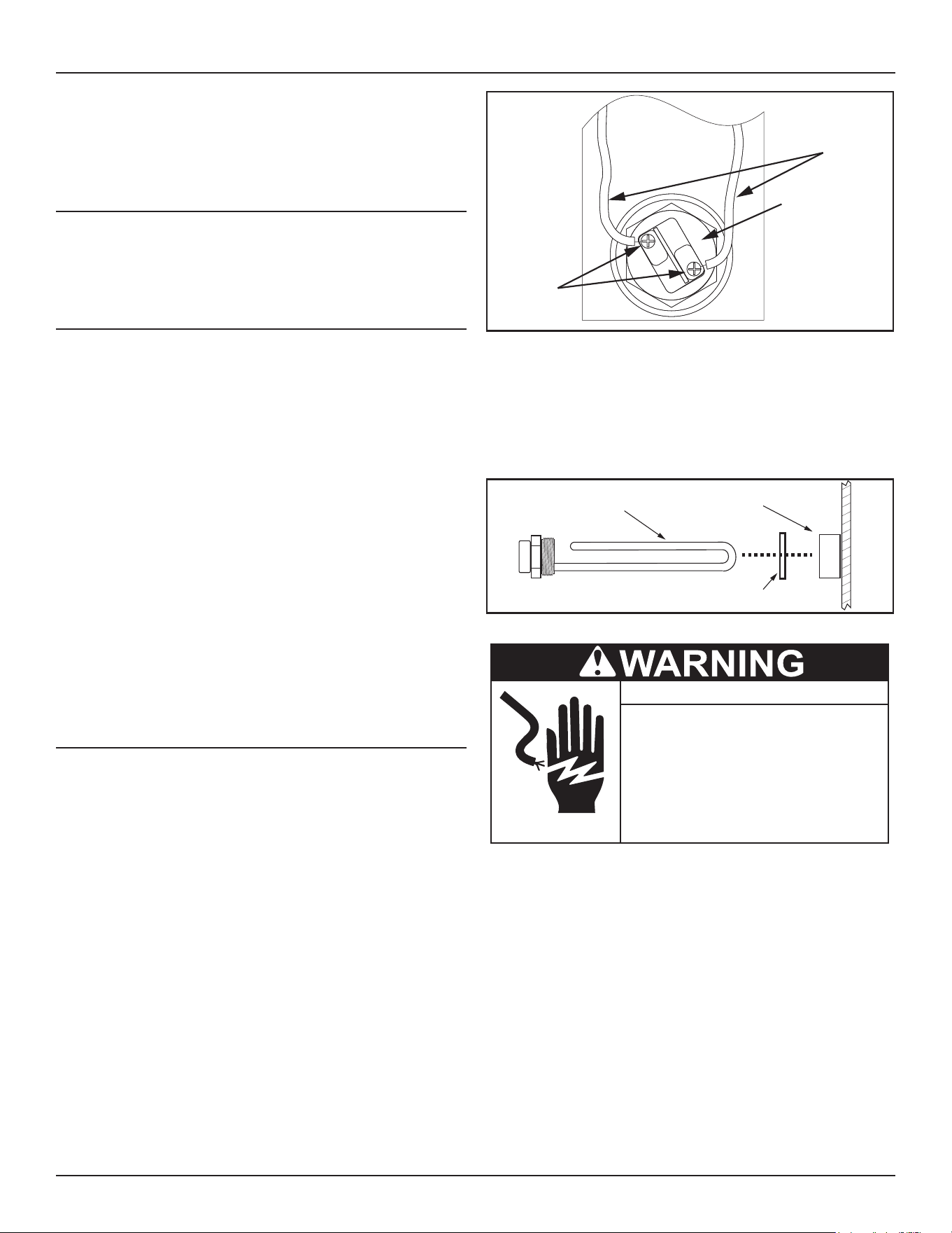
34 • Commercial Electric Heat Pump Water Heater
Maintenance
10. Fill the water heater - see
Filling the Water Heater
(page 21).
11. Turn on the electrical supply to place the water heater back in
operation.
12. Allow the water heater to complete several heating cycles to
ensure it is operating properly.
SEDIMENT REMOVAL
Waterborne impurities consist of the particles of soil and sand which
settle out and form a layer of sediment on the bottom of the tank.
For convenience, sediment removal and lime scale removal should be
performed at the same time.
Lime Scale Removal
Lime scale accumulations on the heating elements is a normal
condition, common to all immersion type elements. Factors which
aect the amounts of this formation are:
1. Amount of hot water used. As the volume of water heated
increases, more scale results.
2. Water temperature. As the temperature of the water is increased,
more scale is deposited on the elements.
3. Characteristics of water supply.
4. Regardless of water treatment, the elements should be examined
regularly.
Lime scale accumulations may cause noises to occur during
operation.
It is recommended that a heating element be removed periodically
for examination. If it is scaled, all of the elements should be removed
and cleaned. If the tank bottom has an accumulation of sediment it
should be cleaned.
Lime scale should be removed by dissolving the accumulation in
UN•LIME® delimer. Do not use muriatic or hydrochloric acid base
deliming solutions to remove lime scale from the elements.
HEATING ELEMENT REPLACEMENT
Replacement heating elements must be of the same style and
Voltage/wattage rating as the ones originally in the water heater.
This information can be found on the ange or terminal block of the
element or on the water heater data plate.
Important: Before replacing any element, conrm that you have
the correct replacement element (wattage). DO NOT
replace the element(s) with a wattage, style or shape
dierent than the elements specied for the upper and/
or lower element.
1. Turn o power to the water heater at the breaker disconnect
switch serving the water heater.
2. Verify there is no power at the incoming power connection to the
water heater with an AC volt meter.
3. Open a nearby hot water faucet and allow to run until the water
is no longer hot.
4. Close the cold water shut-o valve to the heater.
5. Drain the water heater by connecting a hose to the drain valve and
terminating it to an adequate drain or to the exterior of the building.
When unit is drained, close the drain valve and remove hose.
Wires
Element
Screws
Figure 12. Heating Element Wiring
6. Remove the water heater’s left side access panel and the element
access cover.
7. Remove the protective plastic cover from the element.
8. Disconnect the electrical wires from the heating element by
loosening the screws (
Figure 12
). Remove the screw-in element
by turning the element counterclockwise with a 1-1/2 inch socket
wrench. Remove the existing gasket.
Screw-in
Element
Spud
Gasket
Figure 13. Heating Element Components
● Before removing any access panels or
servicing the water heater, make sure
the the electrical supply to the water
heater is turned OFF.
Electrical Shock Hazard
● Failure to follow these instructions can
result in personal injury or death.
9. Clean the area where the gasket ts to the tank. If you are
replacing the bottom element, remove any accumulated sediment
on the bottom of the tank.
10. Make sure the replacement element has the correct voltage and
wattage rating and shape by matching it to the rating plate on
the water heater. Position the new gasket(s) on the element and
insert it into the water heater tank (
Figure 13
). Tighten the element
by turning it clockwise until secure.
11. Close the drain valve and open the nearest hot water faucet.
Then open the cold water shut o valve and allow the tank to ll
completely with water. To purge the lines of any excess air and
sediment, keep the hot water faucet open for three (3) minutes
after a constant ow of water is obtained.
12. Check for leaks around the element.
13. Reconnect the electrical wires to the element and securely tighten
the screws (
Figure 12
).
14. Replace the protective plastic cover removed earlier. Make sure
the covers are securely engaged on the attachment points.
15. Replace the element access cover and water heater panel.
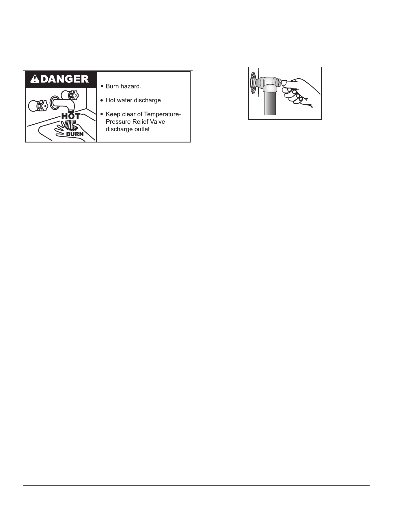
Maintenance
Commercial Electric Heat Pump Water Heater • 35
16. Although this water heater is equipped with “Dry Fire” protection
circuitry, be sure tank is completely lled with water before
applying electrical power to the water heater.
TEMPERATURE-PRESSURE RELIEF VALVE TEST
It is recommended that the Temperature-Pressure Relief Valve
should be checked to ensure that it is in operating condition every
6 months.
When checking the Temperature-Pressure Relief Valve operation,
make sure that (1) no one is in front of or around the outlet of the
Temperature-Pressure Relief Valve discharge line, and (2) that the
water discharge will not cause any property damage, as the water
may be extremely hot. Use care when operating valve as the valve
may be hot.
To check the relief valve, lift the lever at the end of the valve several
times. See
Figure 14
. The valve should seat properly and operate
freely.
If after manually operating the valve, it fails to completely reset and
continues to release water, immediately close the cold water inlet to
the water heater and drain the water heater. See
Draining and Flushing
(page 77). Replace the Temperature-Pressure Relief Valve with
a properly rated/sized new one. See
Temperature-Pressure Relief Valve
(page 24) for instructions on replacement.
Figure 14. Testing the T&P Relief Valve
If the Temperature-Pressure Relief Valve on the water heater weeps
or discharges periodically, this may be due to thermal expansion.
Note: Excessive water pressure is the most common cause of
Temperature-Pressure Relief Valve leakage. Excessive water
system pressure is most often caused by “thermal expansion”
in a “closed system.” See
Closed Water Systems
(page 17)
and
Thermal Expansion
(page 23). The Temperature-Pressure
Relief Valve is not intended for the constant relief of thermal
expansion.
Temperature-Pressure Relief Valve leakage due to pressure build
up in a closed system that does not have a thermal expansion
tank installed is not covered under the limited warranty. Thermal
expansion tanks must be installed on all closed water systems.
Do not plug the Temperature-Pressure Relief Valve opening.
This can cause property damage, serious injury or death.
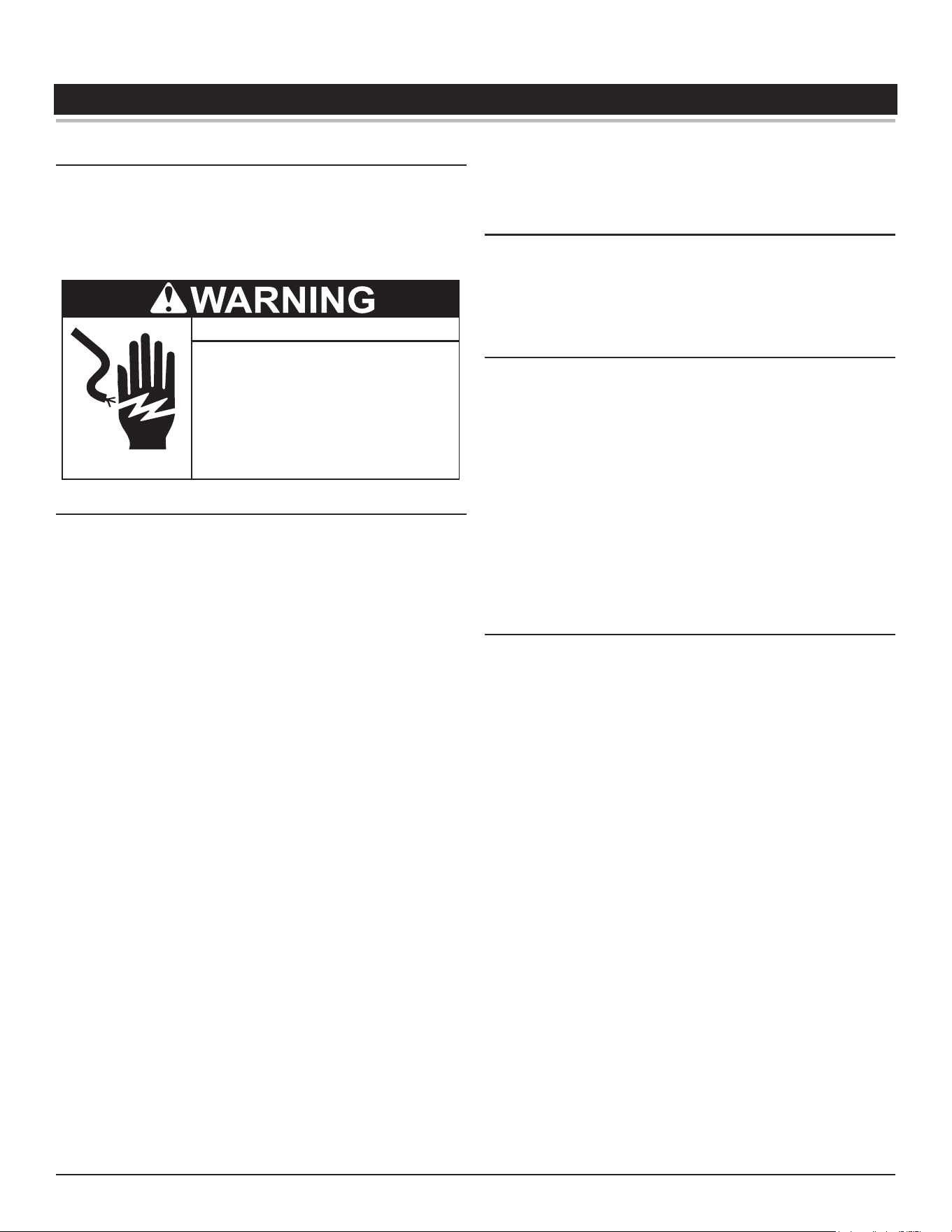
36 • Commercial Electric Heat Pump Water Heater
TROUBLESHOOTING
CHECKLIST
Before calling for service, check the following points to see if the
cause of trouble can be identied and corrected.
Reviewing this checklist may eliminate the need of a service call and
quickly restore hot water service. See
Figure 1
(page 9) in this
manual to identify and locate water heater components.
● Before removing any access panels or
servicing the water heater, make sure
the the electrical supply to the water
heater is turned OFF.
Electrical Shock Hazard
● Failure to follow these instructions can
result in personal injury or death.
Not Enough Or No Hot Water
1. Be certain the electrical disconnect switch serving the water
heater is in the ON position.
2. Check the fuses.
The electrical disconnect switch usually contains fuses.
3. If the water was excessively hot, and is now cold, the high limit
switch may have activated.
4. See the Temperature Regulation section of this manual for more
information on how to reset the ECO high limit controls.
5. The capacity of the heater may have been exceeded by a large
demand for hot water.
6. Large demands require a recovery period to restore water
temperature.
7. Cooler incoming water temperature will lengthen the time required
to heat water to the desired temperature.
8. Look for hot water leakage.
9. Sediment or pipe scale may be aecting water heater operation.
Abnormal Sounds
10. Sediment or lime scale accumulations on the elements causes
sizzling and hissing noises when the heater is operating.
• The sounds are normal, however, the tank bottom and
elements should be cleaned. See the Maintenance section
of this manual.
Water Leakage is Suspected
11. Check to see if the heater drain valve is tightly closed.
12. If the outlet of the relief valve is leaking it may represent:
• Excessive water temperature.
• Faulty relief valve.
• Excessive water pressure.
13. Excessive water pressure is the most common cause of relief
valve leakage. It is often caused by a “closed system”. See
“Closed Water Systems” and “Thermal Expansion” in the
Installation section of this manual for more information.
14. Examine the area around the element for gasket leakage.
• Tighten the elements or, if necessary, follow the WATER
AND LIME SCALE REMOVAL procedure to replace the
gaskets.
If You Cannot Identify Or Correct The Source Of Malfunction
1. Turn the power supply to the water heater o.
2. Close the supply water inlet valve to the heater.
3. Contact Technical Support for further assistance or to locate a
qualied service agent in your area. See the contact information
label on the water heater.
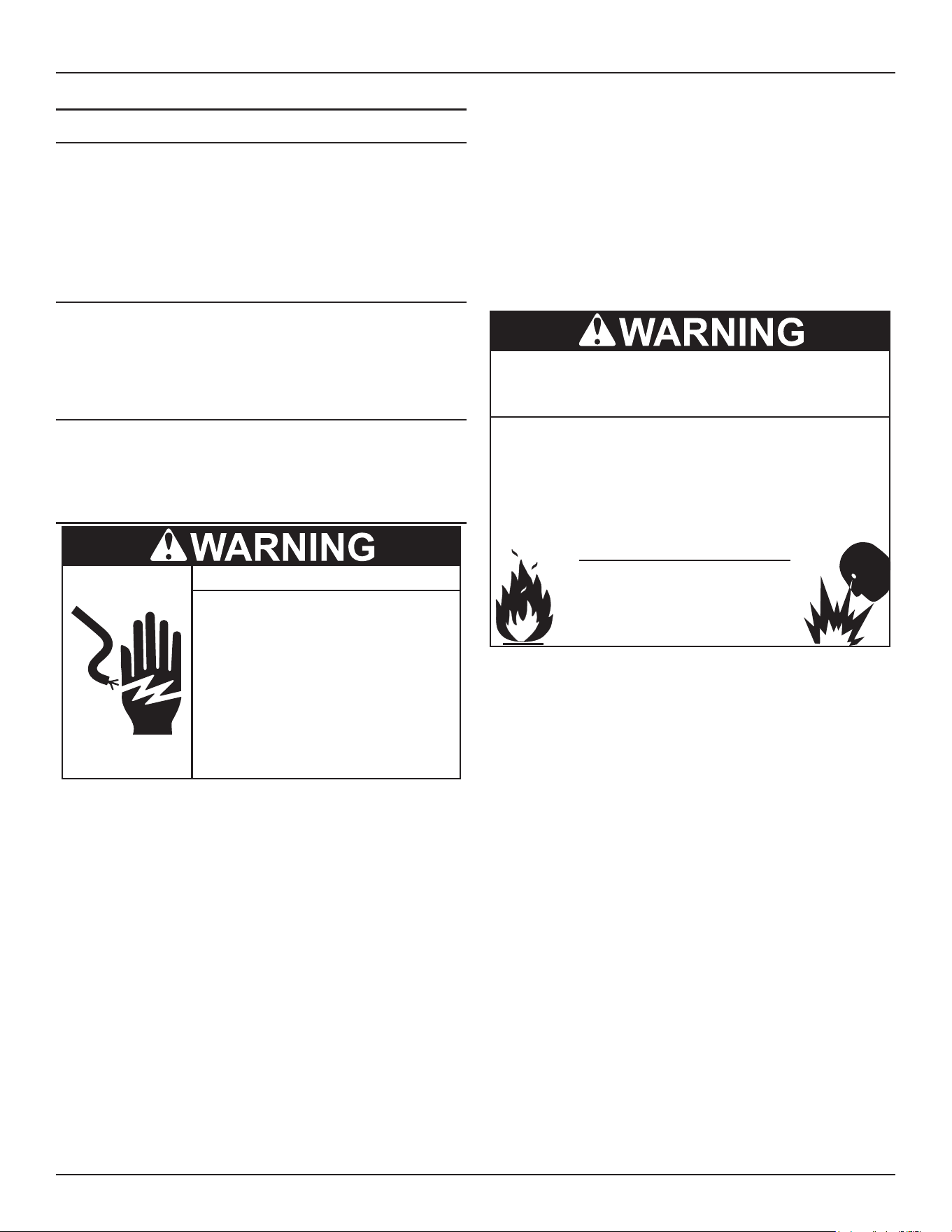
Troubleshooting
Commercial Electric Heat Pump Water Heater • 37
FAULT AND ALERT CONDITIONS
Fault Conditions
When the control system declares a Fault condition it will display a Fault
message on the control system’s LCD with an exclamation “!” mark.
The control system will lock out and disable heating operation until the
condition is corrected. The water heater must be serviced by a qualied
service agent before operation can be restored. Some faults will reset
automatically when the fault condition is corrected. Others will require
the power supply to be turned o at the breaker or disconnect switch
then turned back on.
Alert Conditions
When the control system declares an Alert condition it will display an
Alert message on the control system’s LCD with a question “?” mark.
The water heater will continue to operate during an Alert condition but
the water heater must be serviced by a qualied service agent as soon
as possible.
Resetting Control System Lock Outs
To reset the control system from a lock out condition; turn the power
supply o at the breaker or disconnect switch for approximately 20
seconds and then back on. Keep in mind; if the condition that caused the
Fault has not been corrected, the control system will continue to lock out.
Diagnostic Checks
Turn off power at the branch circuit
breaker serving the water heater
before performing any service.
Electrical Shock Hazard
•
Label all wires prior to disconnecting
when performing service. Wiring errors
can cause improper and dangerous
operation.
•
Verify proper operation after servicing.
•
Failure to follow these instructions can
result in personal injury or death.
•
The following section,
Fault and Alert Messages
(page 38), lists some
of the messages the control system will display on the LCD when there
are operational problems. This is not a complete list. Along with each of
the Fault and Alert messages described there will be a list of possible
causes and things to check and repair.
Only qualied service agents, as dened in
Approvals
(page 3), using
appropriate test equipment, should perform any service procedures on
the water heater.
Note: If you are not qualied and licensed or certied as required
by the authority having jurisdiction to perform a given task
do not attempt to perform any of the diagnostic or service
procedures described in the following section.
If you do not understand the instructions in the following section do not
attempt to perform any procedures.
Call the technical support phone number listed on the back cover of this
manual for further technical assistance or to locate a qualied service
agent in your area.
Jumping out control circuits or components can
result in property damage, personal injury or death.
Service should only be performed by a qualified service
technician using proper test equipment.
•
Altering the water heater controls and/or wiring in any way
could result in permanent damage to the controls or water
heater and is not covered under the limited warranty.
•
Any bypass or alteration of the water
heater controls and/or wiring will result
in voiding the appliance warranty.
38 • Commercial Electric Heat Pump Water Heater
Troubleshooting
Fault and Alert Messages
Call the technical support phone number listed on the water heater for further technical assistance or to locate a qualied service agent
in your area.
Table 12. Diagnostic Codes
Display Shows Error Code Indicates Corrective Action
Relay Error
786
Water temperature is sensed to be
rising when there is no water heating
Recycle electrical power to heater.
Replace main control board.
Top Upper Sensor Fault
787
Upper tank temperature sensor is not
functioning.
Replace upper tank temperature sensor.
Mid-Upper Sensor Fault
788
Mid-upper tank temperature sensor is
not functioning.
Replace mid-upper tank temperature sensor.
Mid-Lower Sensor Fault
789
Mid-lower tank temperature sensor is
not functioning.
Replace mid-lower tank temperature sensor.
Bottom Lower Sensor
Fault
78A
Lower tank temperature sensor is not
functioning.
Replace lower tank temperature sensor.
System Low Voltage Fault
78B
Power supply voltage is too low. Check the power supply to the unit and make sure
it is higher than 198 VAC.
System High Voltage Fault
78C
Power supply voltage is too high. Check the power supply to the unit and make sure
it is lower than 252 VAC.
Dry Fire Fault
78D
Not enough water in tank. Fill unit completely with water. Open a nearby hot
water faucet to permit air in the system to escape.
Close the hot water faucet when water starts to
ow without air interruptions.
Discharge Over
Temperature Fault
78E
Heat pump discharge temperature is
too high.
Contact a qualied installer or service agency
for repair. Refer to phone number listed on the
technical support label located on the unit.
Discharge Sensor Fault
78F
Heat pump discharge temperature
sensor is not functioning.
Contact a qualied installer or service agency
for repair. Refer to phone number listed on the
technical support label located on the unit.
Coil Sensor Fault
790
Coil temperature sensor is not
functioning.
Contact a qualied installer or service agency
for repair. Refer to phone number listed on the
technical support label located on the unit.
Ambient Sensor Fault
791
Ambient temperature sensor is not
functioning.
Contact a qualied installer or service agency
for repair. Refer to phone number listed on the
technical support label located on the unit.
Suction Sensor Fault
792
Heat pump suction sensor is not
functioning.
Contact a qualied installer or service agency
for repair. Refer to phone number listed on the
technical support label located on the unit.
Low Pressure Fault
793
Heat pump low pressure switch is
open.
Contact a qualied installer or service agency
for repair. Refer to phone number listed on the
technical support label located on the unit.
Communication Error
NA
No communication between main
control board and UIM.
Contact a qualied installer or service agency
for repair. Refer to phone number listed on the
technical support label located on the unit.
Upper Contactor
Connection Fault
794
No communication between the main
control board and upper element
contactor and or elements.
1. Turn o power at the breaker or disconnect
switch and check for loose connections at the
contactors, main board, and elements. If error
persists proceed to next step.
2. Replace contactor.
3. Replace main control board.
Power Frequency Fault
0C1
Power supply frequency (Hz) is too
high or too low.
Check the power supply to the unit and make sure
the line frequency is between 56 Hz to 64 Hz.
EEPROM Fault
795
EEPROM Failure Contact a qualied installer or service agency
for repair. Refer to phone number listed on the
technical support label located on the unit.
The diagnostic codes listed above are the most common. If a diagnostic code not listed above is displayed, call the telephone number
listed on the Technical Support label located on the water heater.
Troubleshooting
Commercial Electric Heat Pump Water Heater • 39
Table 13. Troubleshooting Chart
Problem Possible Cause(s) Corrective Action
NO HOT WATER 1. No power to the water heater (No lights on the
unit are on).
2. ECO open
3. Hot water usage pattern exceeds the capability
of the water heater in current mode
4. Non-functioning temperature sensor
5. Faulty thermostatic mixing valve.
6. Leak in plumbing system
1. Check for blown fuse or tripped breaker. Restore
power to unit.
2. Reset the high temperature limit switch; see
High
Temperature Limit Control (ECO)
(page 22) for more
information.
3. Change to different mode or modify usage
patterns.
4. Contact a qualied person for service.
5. Check hot water at other faucets.
6. Check hot water side of home’s plumbing system
for leaks.
INSUFFICIENT HOT
WATER/
SLOW HOT WATER
RECOVERY
1. Temperature set-point too low
2. Hot water usage pattern exceeds the capability
of the water heater in current mode
3. Water connections to unit reversed
4. Heat lost through long run of exposed pipe
5. Hot water leak at faucet or piping
6. Non-functioning heating element
7. Sediment or scale build up in tank
8. Thermostatic mixing valve faulty/set too low.
9. Low supply voltage.
10. Insucient air ow.
11. Installation space too small.
1. Increase set point temperature; see
Operating Set
Point Adjustment
(page 27).
2. Change to dierent mode or modify usage patterns
(For example if in Eciency Mode, switch to Hybrid
Mode).
3. Ensure the cold connection is at the bottom and
that the hot connection is at the top
4. Insulate exposed piping
5. Repair hot water leaks
6. Call qualied person for service
7. Drain and ush tank. Water conditioning may be
necessary to minimize build up.
8. Check hot water at other faucets.
9. Check power (voltage).
TEMPERATURE TOO
HIGH
1. Non Functioning ECO switch.
2. Non functioning thermostat.
3. Grounded/shorted heating element.
4. Thermostatic mixing valve faulty.
1. Replace ECO switch.
2. Replace tank temperature sensors.
3. Replace heating element.
4. Check hot water at other faucets.
LOW WATER
PRESSURE
Partially closed supply valve Open supply valve completely.
WATER ODOR 1. A concentration of sulfate in the supply water
2. Little or no dissolved oxygen in the water.
3. A sulfate reducing bacteria which has accumulated
within the water heater (this harmless bacteria is
nontoxic to humans).
4. An excess of active hydrogen in the tank. This
is caused by the corrosion protective action of
the anode.
Replace anode.
SOUNDS 1. Normal expansion and contraction of metal parts
during periods of heat-up and cool-down.
2. Sediment buildup on or around the elements.
3. The heat pump compressor or fan running.
1. No action required.
2. Drain and ush the tank as directed. See the
Draining and Flushing section.
3. No action required.
DRIP FROM
TEMPERATURE &
PRESSURE RELIEF
VALVE
1. Excessive water pressure
2. Add or service a thermal expansion tank.
3. Non-functioning Temperature & Pressure Relief
Valve
4. Debris under valve seat.
1. Check water supply inlet pressure. If higher than 80
PSIG, install a pressure reducing valve. (A 50-60
PSIG valve is recommended.)
2. See Water Pressure Increase Caused by Thermal
Expansion section on page nn.
3. Replace the temperature & pressure relief valve.
4. See the
Water Leakage is Suspected
(page 36).
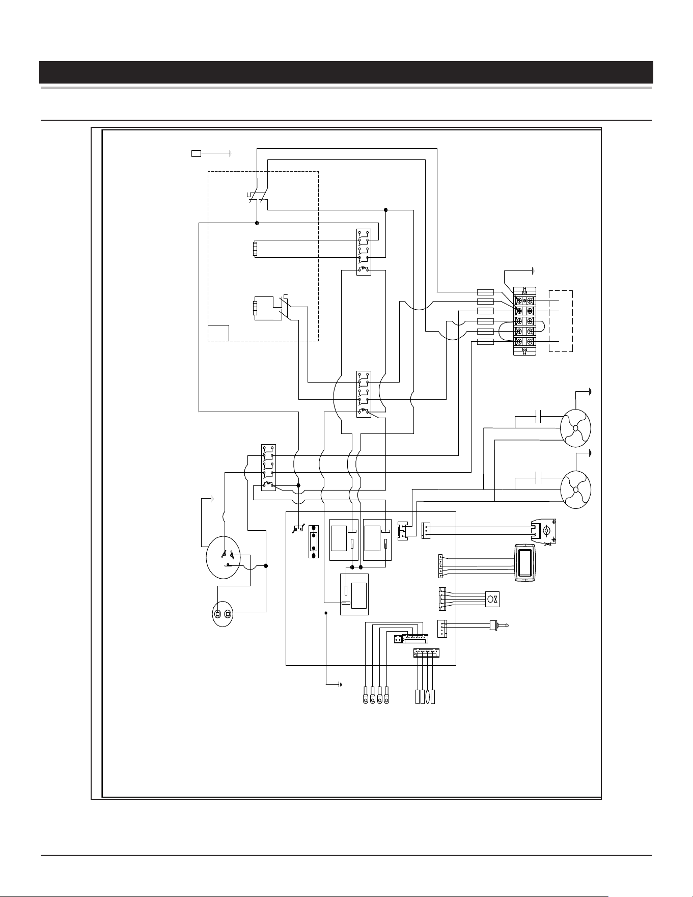
40 • Commercial Electric Heat Pump Water Heater
DIAGRAMS
WIRING DIAGRAMS
A1
A2
NCNC
M
2 T1
4 T2
6 T3
1 L1
3 L2
5 L3
L1
X X
L2
L2
G
TERMINAL
BLOCK
GREEN/YELLOW
FIELD
WIRING
GREEN
RED
TANK
WRITE
BLUE
BLACK
L INPUT
LOWER
(GREEN)
L INPUT
UPPER
(RED)
L INPUT
COMP.
(BLACK)
FOUR-WAY
VALVE
ELECTRONIC
EXPANSION
VALVE
LOWER PRESSURE
SWITCH
UIM
FAN
A1 A2
NCNC
2 T1
4 T2
6 T3
1 L1
3 L2
5 L3
A1
A2
NONO
2 T1
4 T2
6 T3
1 L1
3 L2
5 L3
C
R
S
208/240VAC 60Hz 1Φ
FUSE
SUCTION TEMP. SENSOR
AMBIENT TEMP. SENSOR
COIL TEMP. SENSOR
DISCHARGE TEMP. SENSOR
TANK UPPER TEMP. SENSOR
TANK MID-UPPER TEMP. SENSOR
TANK MID-LOWER TEMP. SENSOR
TANK LOWER TEMP. SENSOR
RTD
RED
BLUE
GREEN
BLUE
BLUE
BLUE
BLUE
BLUE
BLUE
BLUE
RED
BROWN
GREEN
ORANGE
AC
CONTACTOR 3
AC
CONTACTOR 2
AC
CONTACTOR 1
BLACK
LOWER ELEMENT
UPPER ELEMENT
ECO
TANK JA
CKET
TANK
GROUNDING
COMPRESSOR
COMPRESSOR
PROTECTOR
CAPACITOR
RED
GREEN
N_IN
L1
ORANGE
ORANGE
FAN
FUSE
Figure 15. Wiring Diagram
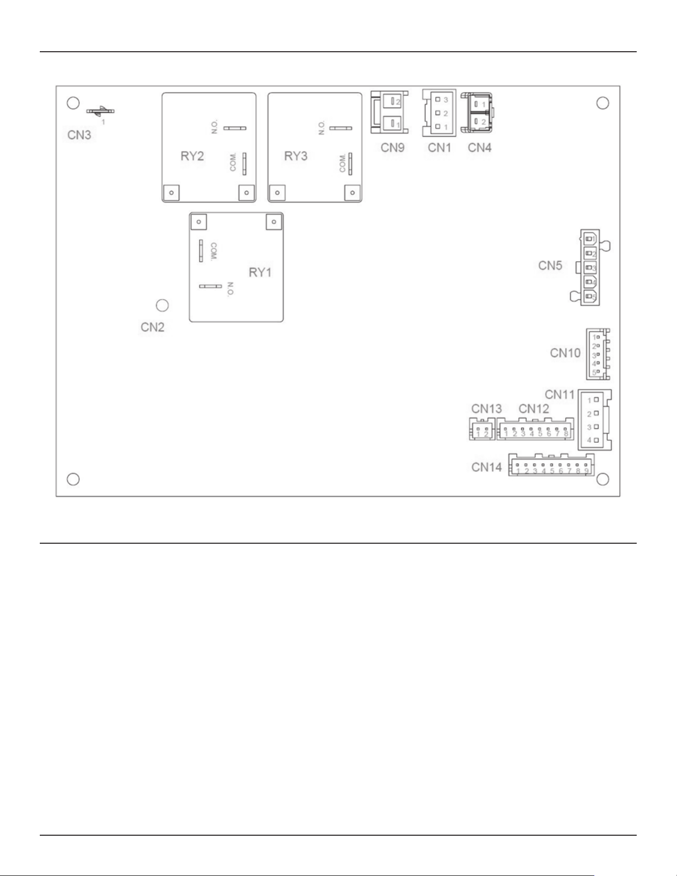
Diagrams
Commercial Electric Heat Pump Water Heater • 41
Figure 16. Main Control Board (CCB) Layout
MAIN CONTROL BOARD (CCB) CONNECTION IDENTIFICATION
CN1 - Four Way Valve Switch
CN2 - Main Control Board (CCB) Ground
CN3 – Main Control Board (CCB) Power In
CN4 – Not Used
CN5 – UIM Communication Interface
CN9 – Fan Switch
CN10 – Electronic Expansion Valve (EEV)
CN11 – Low Pressure Switch
CN12 – Tank Temperature Sensors
CN13 - Not Used
CN14 – Discharge, Coil, Ambient, and Suction Temperature Sensors
RY1 – Lower Element Relay
RY2 – Upper Element Relay
RY3 – Compressor Relay
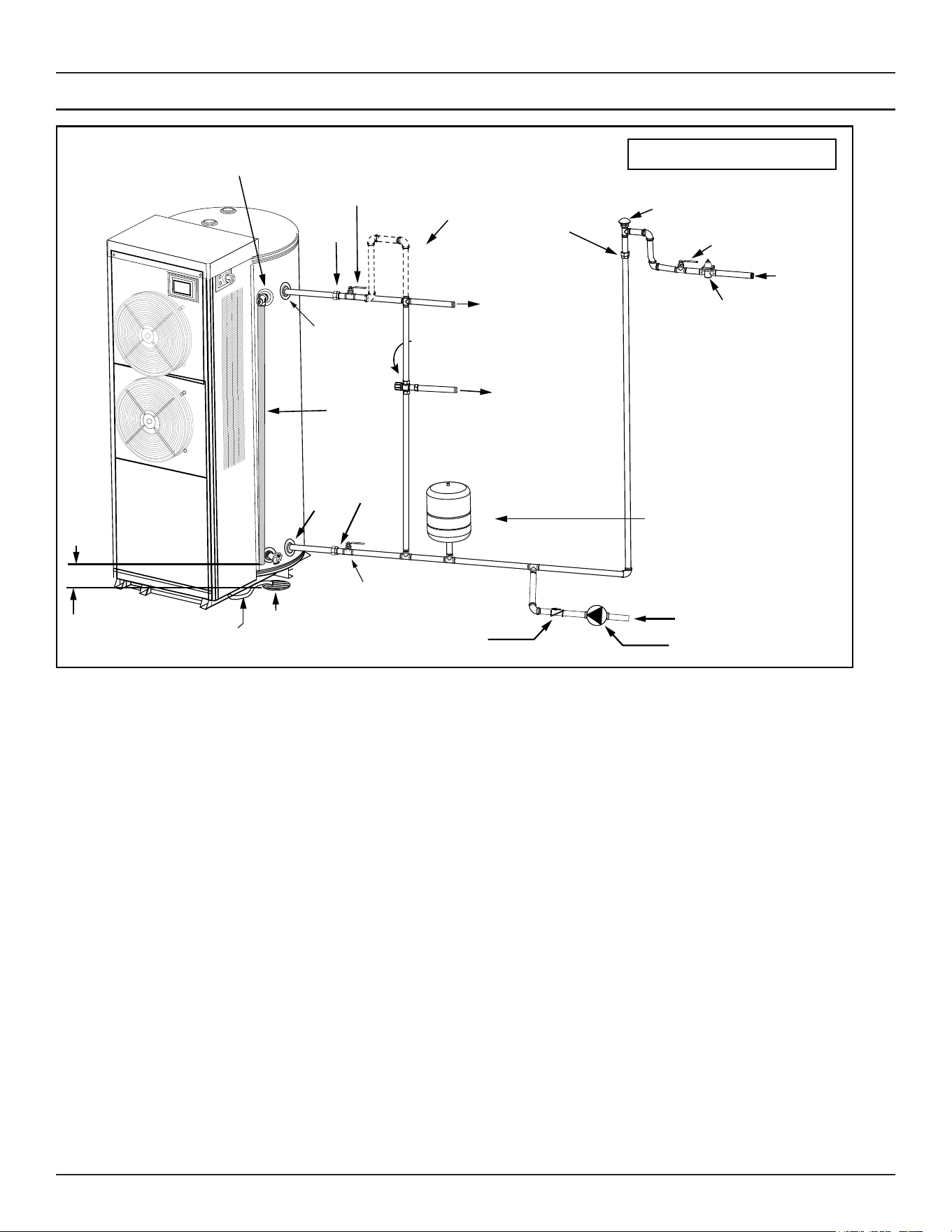
42 • Commercial Electric Heat Pump Water Heater
Diagrams
PIPING DIAGRAM
Vacuum Relief Valve
(when required by local code)
Cold Water
Inlet Valve
Massachusetts: Install a vacuum relief in
cold water line per section 19 MGL 142.
Cold Water
Inlet
Pressure Reducing Valve (PRV)
should be installed where the water
supply enters the building.
When installed PRVs create a
closed water system, a thermal
expansion tank must be installed.
* If an adequate drain is not available for the condensate drain lines then a condensate pump must be used.
In a closed system, use a
thermal expansion tank.
See “Closed System/
Thermal Expansion”
section.
6” Maximum
Air Gap
Shut-off Valve
(Cold)
Optional Mixing Valve - Follow the Mixing
Valve’s Manufacturer’s Installation
Instructions. (Set to 120°F / 48.8°C)
Shut-off Valve (Hot)
Union
T&P Discharge Pipe
(Do Not Cap or Plug)
Union
Drain
Cold
(Inlet)
Hot
(Outlet)
Union
Temperature and
Pressure Relief Valve
Optional Heat
Trap Piping
Tempered Water
to Fixtures
Untempered Water Outlet
* Primary Condensate
Drain (3/4” Flex Tube)
Recirculation Loop Return
Circulating Pump
Check Valve
Figure 17. Completed Water System Piping

Commercial Electric Heat Pump Water Heater • 43
NOTES

Copyright © 2022 . All rights reserved.