PLACE THESE INSTRUCTIONS ADJACENT TO HEATER AND NOTIFY OWNER TO KEEP FOR FUTURE REFERENCE.
KEEP THIS MANUAL IN THE POCKET ON HEATER FOR FUTURE REFERENCE WHENEVER MAINTENANCE
ADJUSTMENT OR SERVICE IS REQUIRED.
100358519_2000616907 Rev B
Instruction Manual
COMMERCIAL ELECTRIC WATER HEATERS
300 Maddox Simpson Parkway
Lebanon, TN 37090
Technical Service Phone: 1-800-722-2101
Technical Service email: 2tech@lochinvar.com
www.Lochinvar.com
LOW LEAD
CONTENT
LISTED
Thank you for buying this energy efcient water heater. We
appreciate your condence in our products.
Read and understand this instruction
manual and the safety messages
herein before installing, operating or
servicing this water heater.
Failure to follow these instructions and
safety messages could result in death
or serious injury.
This manual must remain with the
water heater.
MODELS LHS 50/80/119 Series 100
& LHC 50/80/119 Series 100
Installation - Service
- Maintenance - Operation
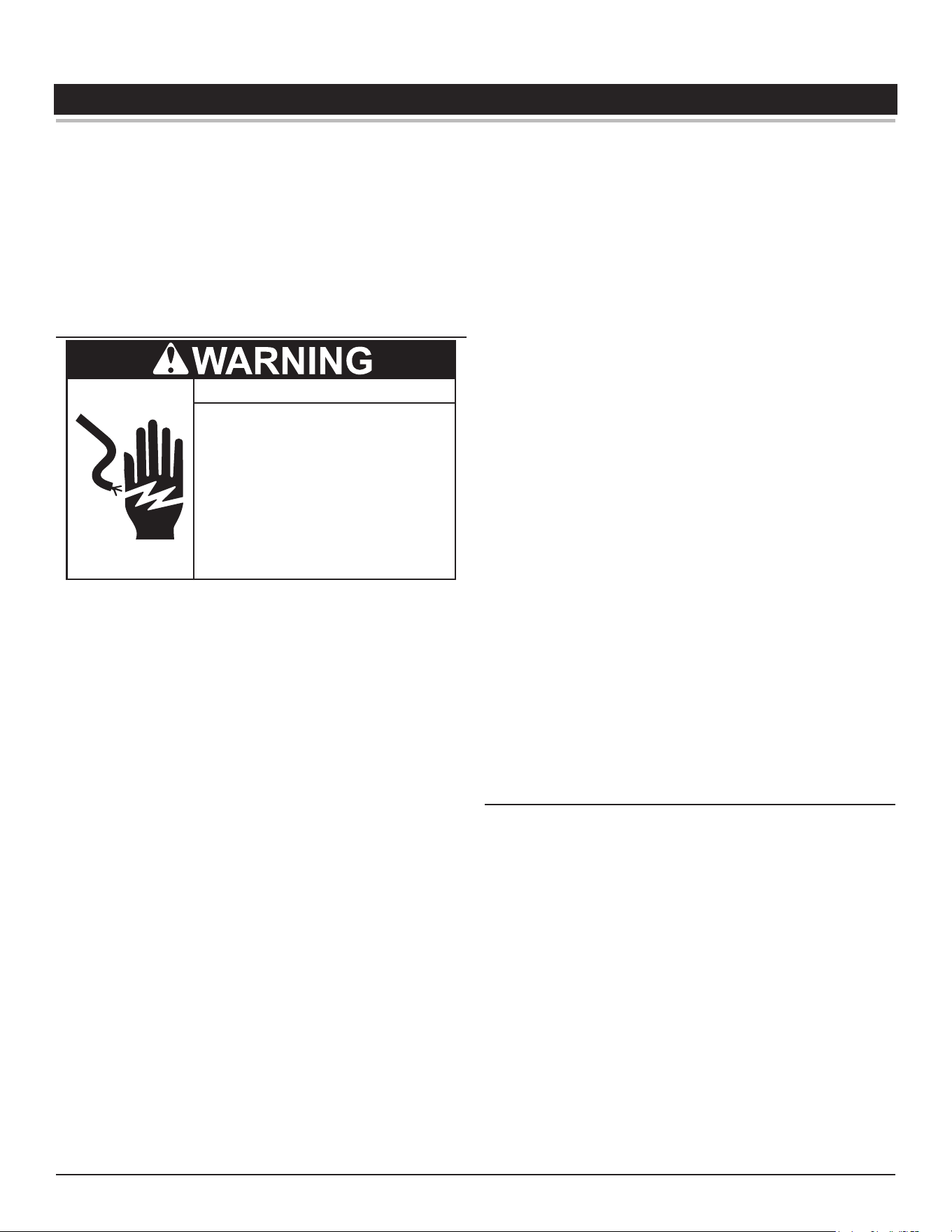
If the water heater becomes immersed in water up to or
above the level of the bottom of the element doors,
the heater should be examined by a qualified service
agency before it is placed in operation.
Electrical Shock Hazard

2
CONTENTS
SAFE INSTALLATION, USE, AND SERVICE ....................................3
Important Definitions ............................................................ 3
APPROVALS.......................................................................................3
GENERAL SAFETY INFORMATION .................................................4
Do Not Operate if Damaged ................................................. 4
Grounding Instructions ......................................................... 4
Limiting the Risk of Scalding ................................................ 4
Hydrogen Gas (Flammable) ................................................. 4
Hazard Messages ................................................................ 5
INTRODUCTION ................................................................................7
Preparing for the Installation ................................................ 7
General ................................................................................ 7
FEATURES AND COMPONENTS .....................................................8
LHS/LHC Model Differences ................................................8
Model and Rating Plate ...................................................... 10
INSTALLATION CONSIDERATIONS ............................................... 11
Locating the Water Heater ................................................. 11
INSTALLING THE WATER HEATER ...............................................12
Required Ability .................................................................. 12
Thermostatic Point-of-Use Mixing Valves ........................... 12
Contaminated Water .......................................................... 12
Circulating Pump ................................................................ 13
Insulation Blankets ............................................................. 13
Temperature-Pressure Relief Valve .................................... 13
Water Line Connections ..................................................... 14
Closed Water Systems ....................................................... 14
Thermal Expansion ............................................................ 14
Electrical ............................................................................ 14
START UP AND OPERATION ..........................................................17
Filling The Water Heater .................................................... 17
Initial Start Up .................................................................... 17
TEMPERATURE REGULATION ......................................................18
Limiting the Risk of Scalding .............................................. 18
High Temperature Limit Controls (ECO) ............................. 18
Surface Mount Control Models ........................................... 18
Electronic Control Models .................................................. 18
Thermostat Controls .......................................................... 18
Thermostat Settings - Surface Mount Control ................... 19
Thermostat Settings - Electronic Controls ......................... 19
CONTROL SYSTEM OPERATION ..................................................21
Temperatures Menu ........................................................... 24
Heater Status Menu ........................................................... 27
Economy Mode Setup Menu .............................................. 28
Economy Mode Settings .................................................... 29
Time Clock Settings ........................................................... 30
Daily Operating Mode Settings ........................................... 32
Alarm Output Setup Menu .................................................. 34
Display Settings Menu ....................................................... 35
Heater Information Menu ................................................... 35
Current Fault / Alert Menu .................................................. 36
Fault History Menu ............................................................. 36
Fault Occurrence Menu ...................................................... 37
Restore Factory Defaults Menu .......................................... 37
MAINTENANCE ................................................................................38
Anode Rod Maintenance .................................................... 38
Temperature-Pressure Relief Valve Test ............................ 39
Draining And Flushing ........................................................ 39
Sediment Removal ............................................................. 39
Lime Scale Removal .......................................................... 39
TROUBLESHOOTING ......................................................................41
Not Enough or No Hot Water ............................................. 41
Water Is Too Hot ................................................................ 41
Water Heater Makes Strange Sounds ................................ 41
If You Cannot Identify or Correct the Source
of Malfunction: ................................................................... 41
Checking for Leaks ............................................................ 42
DIAGRAMS .......................................................................................43
Wiring Diagrams ................................................................ 43
Piping Diagrams ................................................................. 49
Commercial Electric Water Heaters • 3
SAFE INSTALLATION, USE, AND SERVICE
The proper installation, use, and servicing of this water heater is
extremely important to your safety and the safety of others.
Many safety-related messages and instructions have been provided
in this manual and on your own water heater to warn you and others
of a potential injury hazard. Read and obey all safety messages
and instructions throughout this manual. It is very important that the
meaning of each safety message is understood by you and others
who install, use, or service this water heater.
DANGER
WARNING
CAUTION
CAUTION
DANGER indicates an imminently
hazardous situation which, if not avoided,
will result in injury or death.
This is the safety alert symbol. It is used to alert you to
potential personal injury hazards. Obey all safety
messages that follow this symbol to avoid possible
injury or death. Keep this manual near the water heater.
WARNING indicates a potentially hazardous
situation which, if not avoided, could result
in injury or death.
CAUTION indicates a potentially hazardous
situation which, if not avoided, could result in
minor or moderate injury.
CAUTION used without the safety alert
symbol indicates a potentially hazardous
situation which, if not avoided, could result in
property damage.
All safety messages will generally tell you about the type of hazard, what can happen if you do not follow the safety message, and how
to avoid the risk of injury.
IMPORTANT DEFINITIONS
• Qualied Installer or Service Agency:
Installation and service of this water heater requires ability
equivalent to that of a Qualied Agency (as dened by ANSI
below) in the eld involved. Installation skills such as plumbing
and electrical supply are required in addition to electrical testing
skills when performing service.
• ANSI Z223.1 2006 Sec. 3.3.83:
“Qualified Agency” - “Any individual, firm, corporation or
company that either in person or through a representative is
engaged in and is responsible for (a) the installation, testing
or replacement of gas piping or (b) the connection, installation,
testing, repair or servicing of appliances and equipment; that
is experienced in such work; that is familiar with all precautions
required; and that has complied with all the requirements of the
authority having jurisdiction.”
APPROVALS
LOW LEAD
CONTENT
LISTED
4 • Commercial Electric Water Heaters
GENERAL SAFETY INFORMATION
DO NOT OPERATE IF DAMAGED
DO NOT USE THIS WATER HEATER IF ANY PART HAS BEEN
EXPOSED TO FLOODING OR WATER DAMAGE. Immediately
call a qualied service technician to inspect the water heater and to
replace any part of the control system which has been under water.
If the unit is exposed to the following, do not operate heater until all
corrective steps have been made by a qualied service technician.
1. External re.
2. Damage.
3. Firing without water.
GROUNDING INSTRUCTIONS
This water heater must be grounded in accordance with the National
Electrical Code and/or local codes. These must be followed in all cases.
Failure to ground this water heater properly may also cause erratic
control system operation on electronic control models.
This water heater must be connected to a grounded metal,
permanent wiring system, or an equipment grounding conductor must
be run with the circuit conductors and connected to the equipment
grounding terminal or lead on the water heater.
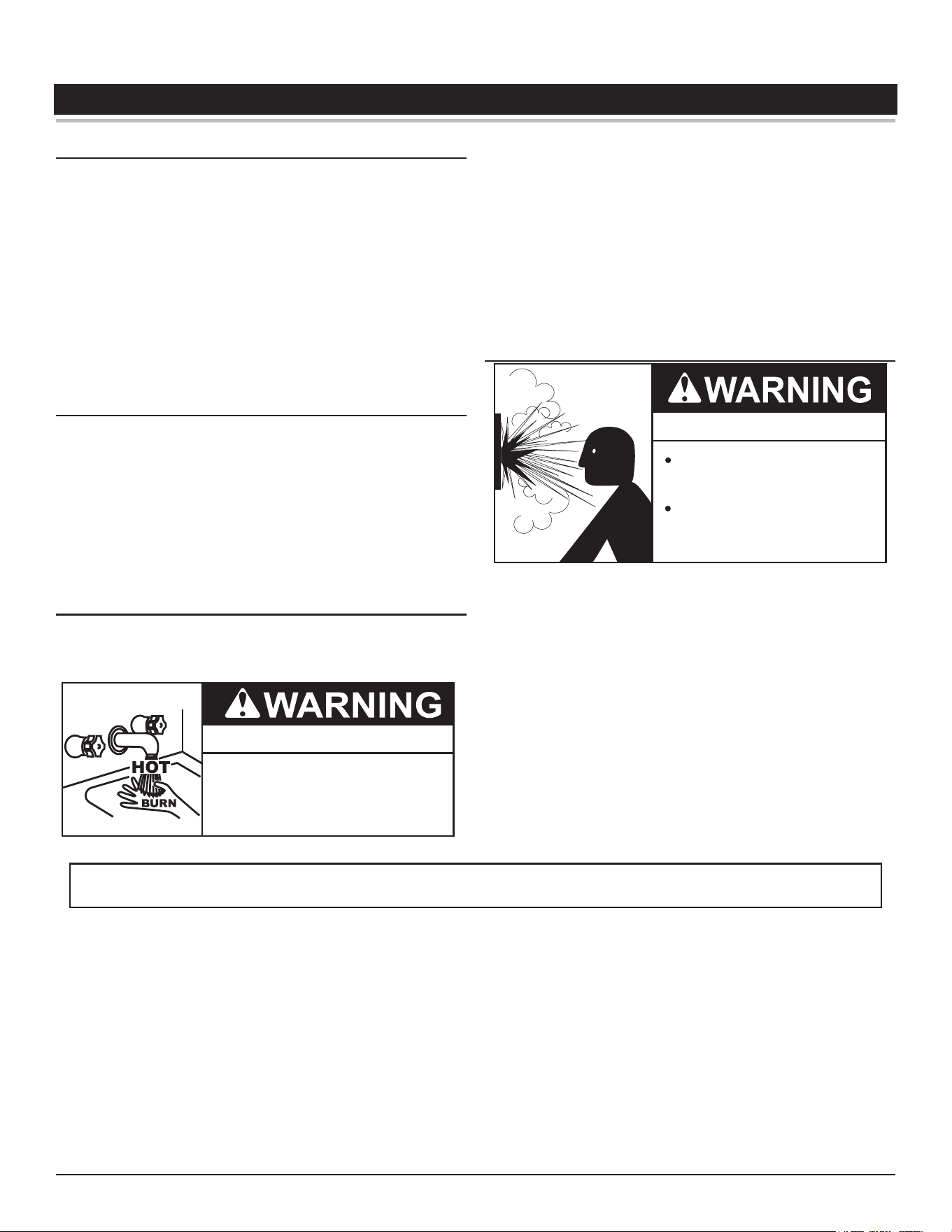
LIMITING THE RISK OF SCALDING
For a variety of reasons, water heaters can produce water that is
much hotter than its temperature setting. Take precautions to prevent
this higher temperature water from reaching the water xtures.
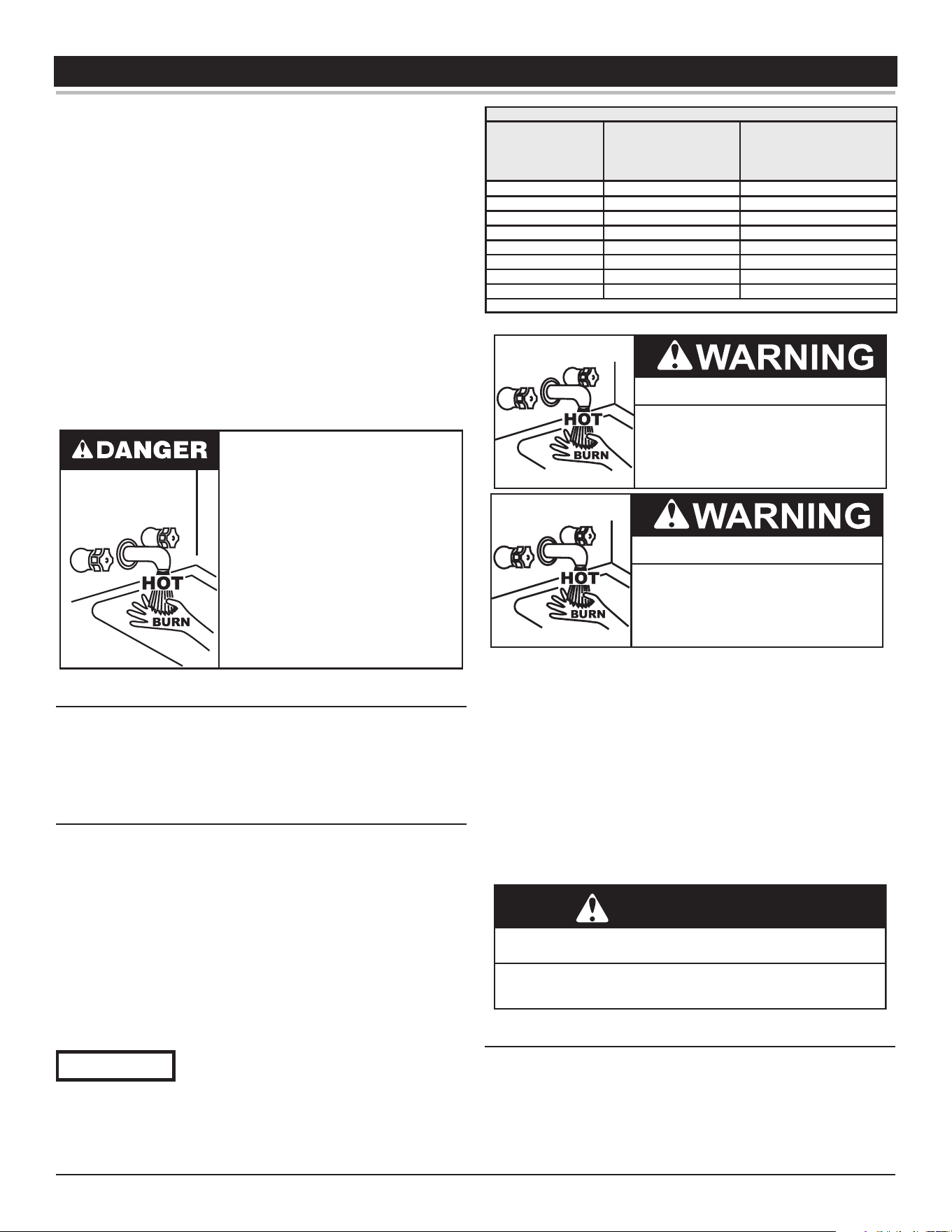
Burn Hazard
To reduce the risk of unusually hot
water reaching the fixtures in the
house, install thermostatic mixing
valves at each point of use.
According to a national standard , Performance Requirements for Water
Temperature Limiting Devices (ASSE 1070) and many local plumbing
codes, the water heater’s gas control valve should not be used as
the sole means to regulate water temperature and avoid scalds.
A properly adjusted thermostatic mixing valve at each point of use
allows you to set the tank temperature to a higher setting without
increasing risk of scalds. A higher temperature setting allows the
tank to provide much more hot water and can help provide proper
water temperatures for appliances such as dishwashers and washing
machines.
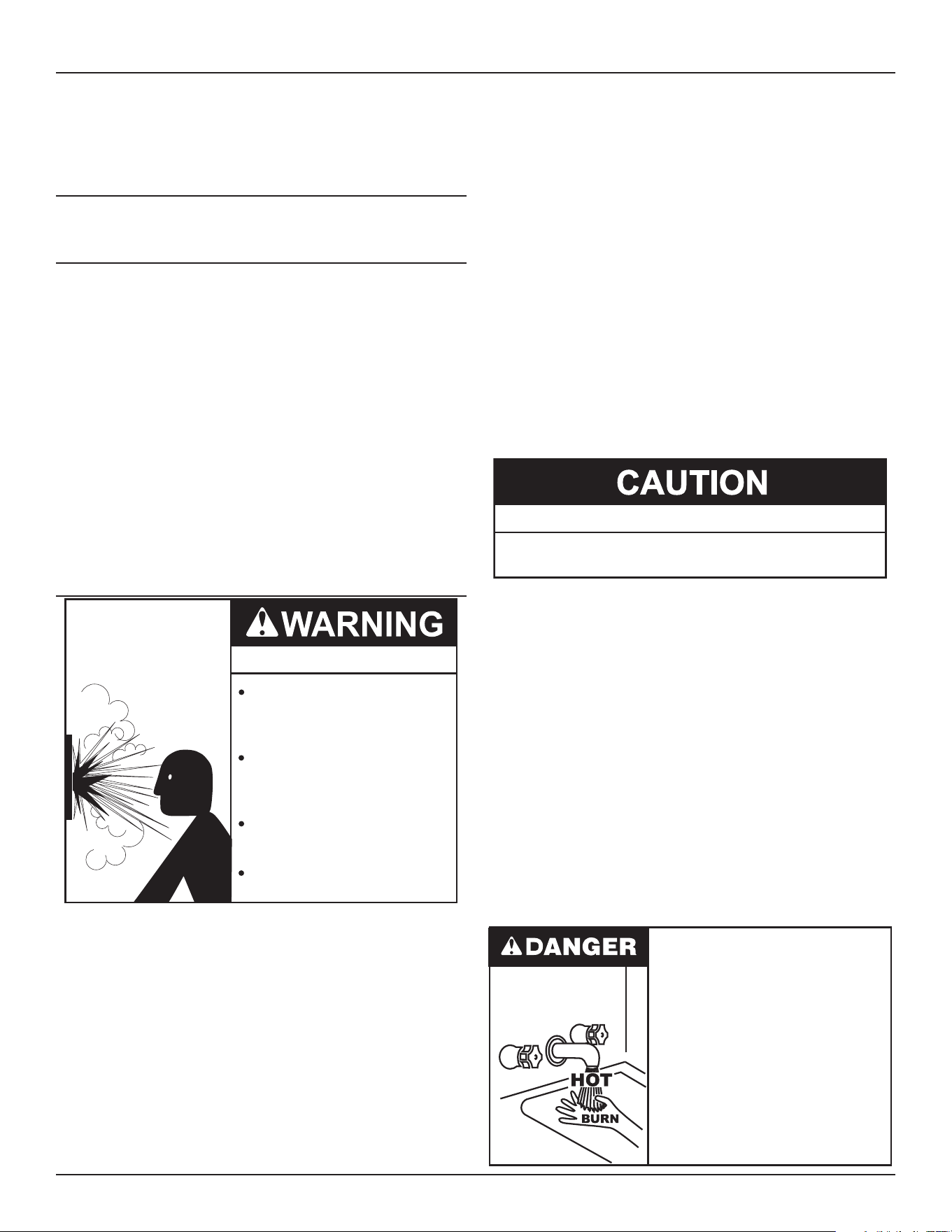
HYDROGEN GAS (FLAMMABLE)
Explosion Hazard
Flammable hydrogen gases
may be present.
Keep all ignition sources away
from faucet when turning on
hot water.
Hydrogen gas can be produced in a hot water system served by this
heater that has not been used for a long period of time (generally two
weeks or more). Hydrogen gas is extremely ammable. To reduce
the risk of injury under these conditions, it is recommended that the
hot water faucet be opened for several minutes at the kitchen sink
before using any electrical appliance connected to the hot water
system. If hydrogen is present there will probably be an unusual
sound such as air escaping through the pipe as the water begins to
ow. THERE SHOULD BE NO SMOKING OR OPEN FLAME NEAR
THE FAUCET AT THE TIME IT IS OPEN.
Verify the power to the water heater is turned o before performing any service procedures. The Enable /Disable switch
on front panel disables the gas valve. Electrical supply must be turned o at circuit breaker serving water heater.
General Safety Information
Commercial Electric Water Heaters • 5
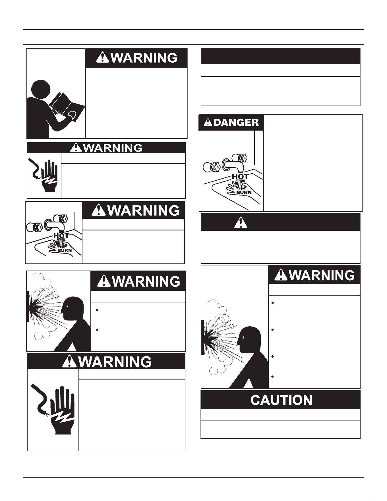
HAZARD MESSAGES
Read and understand this instruction
manual and the safety messages
herein before installing, operating or
servicing this water heater.
Failure to follow these instructions and
safety messages could result in death
or serious injury.
This manual must remain with the
water heater.
If the water heater becomes immersed in water up to or
above the level of the bottom of the element doors,
the heater should be examined by a qualified service
agency before it is placed in operation.
Electrical Shock Hazard
Burn Hazard
To reduce the risk of unusually hot
water reaching the fixtures in the
house, install thermostatic mixing
valves at each point of use.
Explosion Hazard
Flammable hydrogen gases
may be present.
Keep all ignition sources away
from faucet when turning on
hot water.
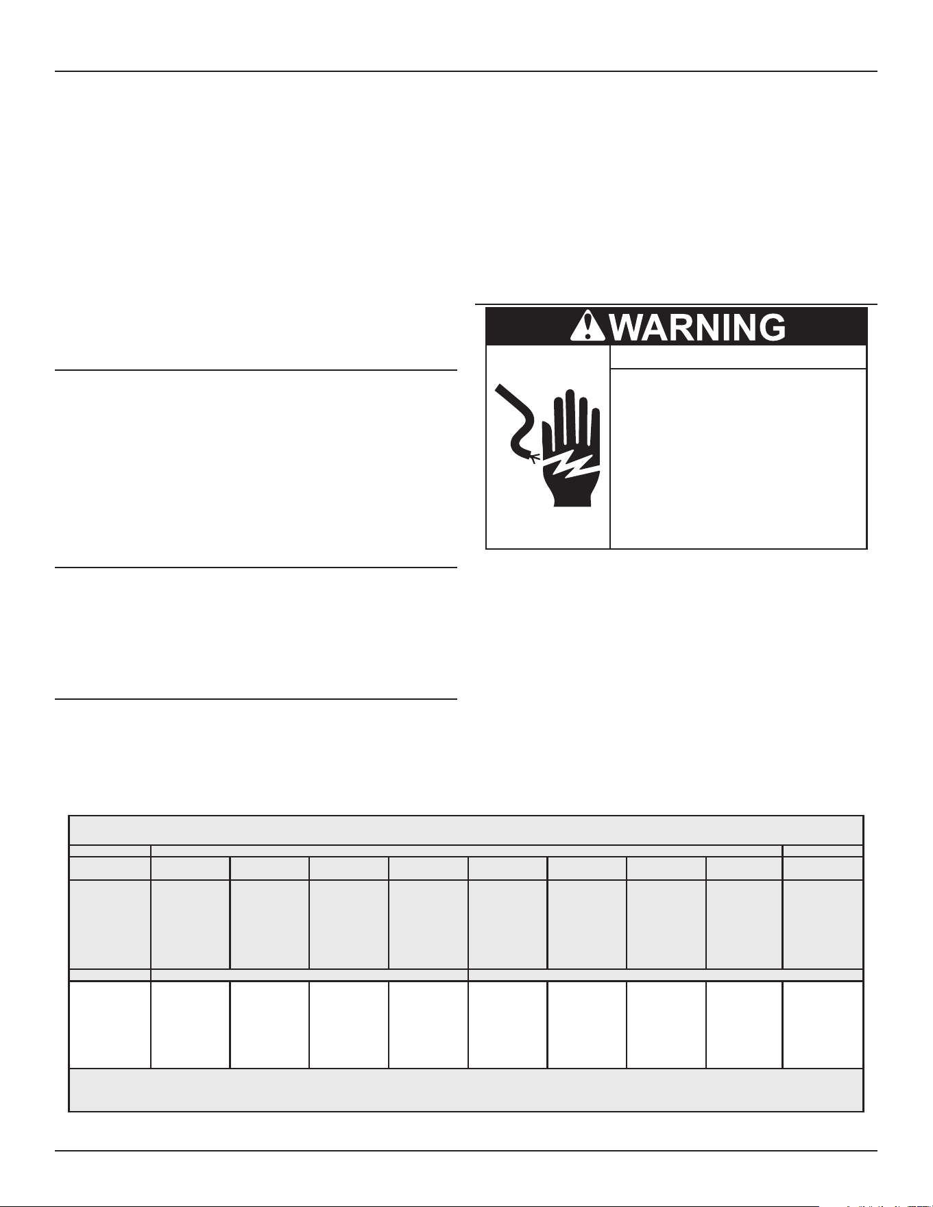
Turn off power to the water heater
before performing any service.
Electrical Shock Hazard
•
Label all wires prior to disconnecting
when performing service. Wiring errors
can cause improper and dangerous
operation.
•
Verify proper operation after servicing.
•
Failure to follow these instructions can
result in personal injury or death.
•
Property Damage Hazard
•
All water heaters eventually leak.
•
Do not install without adequate drainage.
CAUTION
Water temperature over 125°F (52°C)
can cause severe burns instantly
resulting in severe injury or death.
Children, the elderly and the
physically or mentally disabled are at
highest risk for scald injury.
Feel water before bathing or shower-
ing.
Temperature limiting devices such as
thermostatic point-of-use mixing
valves must be installed when
required by codes and to ensure safe
temperatures at fixtures.
Toxic Chemical Hazard
WARNING
● Do not connect to non-potable water system.
Explosion Hazard
Temperature-Pressure Relief Valve
must comply with ANSI Z21.22-
CSA 4.4 and ASME code.
Properly sized temperature-
pressure relief valve must be
installed in opening provided.
Can result in overheating and
excessive tank pressure.
Can cause serious injury or death.
Property Damage Hazard
● The temperature-pressure relief-valve discharge pipe
must terminate at an adequate drain.
6 • Commercial Electric Water Heaters
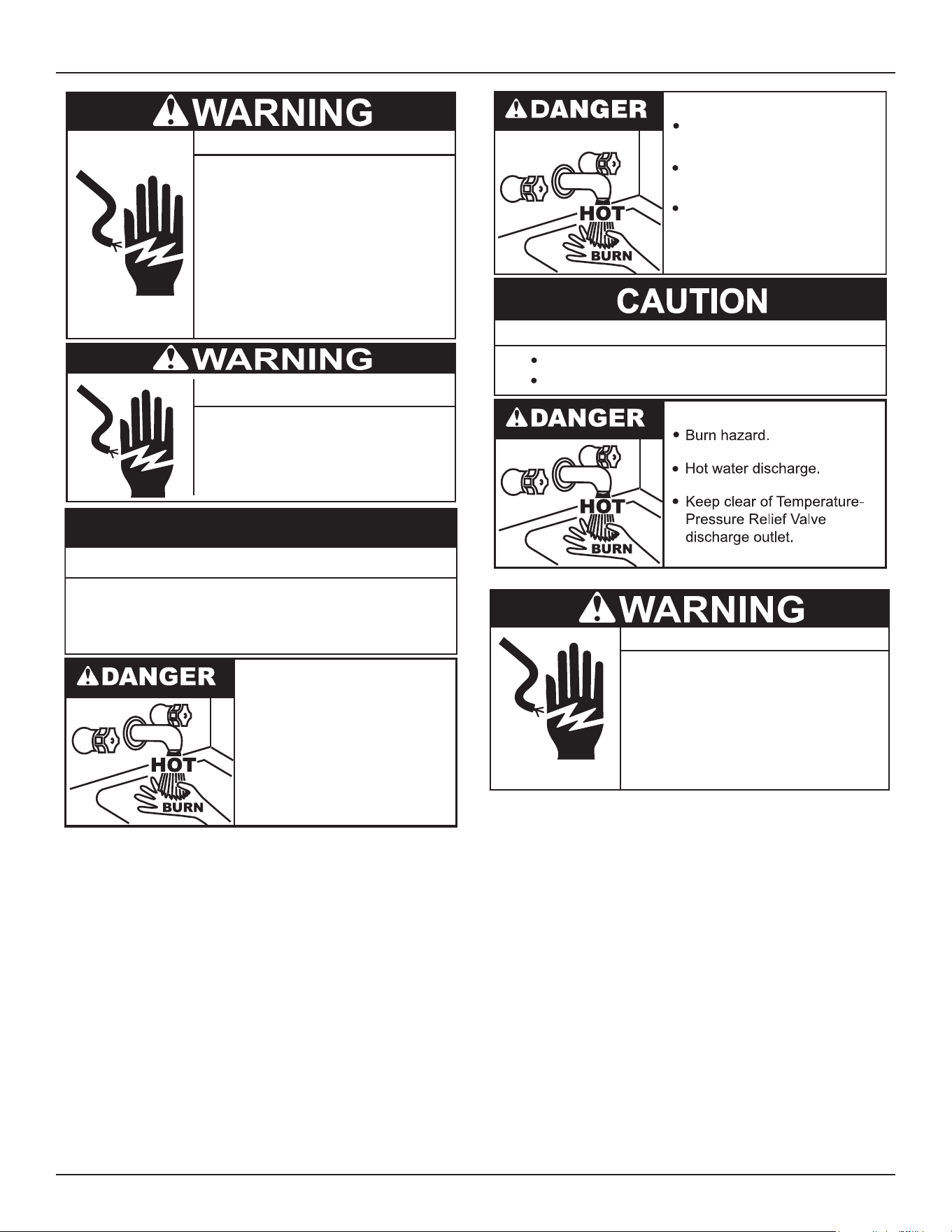
General Safety Information
Turn off power at the branch circuit
breaker serving the water heater
before performing any service.
Electrical Shock Hazard
•
Label all wires prior to disconnecting
when performing service. Wiring errors
can cause improper and dangerous
operation.
•
Verify proper operation after servicing.
•
Failure to follow these instructions can
result in personal injury or death.
•
Full power is present whenever the
cabinet door is opened, even with
the pilot switch turned off.
Electrical Shock Hazard
Property Damage Hazard
To avoid water heater damage, fill tank with water
before operating.
CAUTION
• Burn hazard.
• Hot water discharge.
• Keep hands clear of drain
valve discharge.
Burn hazard.
Hot water discharge.
Keep clear of the Relief Valve
discharge outlet.
Avoid damage.
Property Damage Hazard
Inspection and replacement of anode rod required.
● Before removing any access panels or
servicing the water heater, make sure
the the electrical supply to the water
heater is turned OFF.
Electrical Shock Hazard
● Failure to follow these instructions can
result in personal injury or death.
Commercial Electric Water Heaters • 7
INTRODUCTION
Thank You for purchasing this water heater. Properly installed and
maintained, it should give you years of trouble free service.
Abbreviations Found In This Instruction Manual:
• AHRI - Air Condition, Heating and Refrigeration Institute
• ANSI - American National Standards Institute
• ASME - American Society of Mechanical Engineers
• NEC - National Electrical Code
• NFPA - National Fire Protection Association
• UL - Underwriters Laboratory
PREPARING FOR THE INSTALLATION
Turn off power to the water heater
before performing any service.
Electrical Shock Hazard
•
Label all wires prior to disconnecting
when performing service. Wiring errors
can cause improper and dangerous
operation.
•
Verify proper operation after servicing.
•
Failure to follow these instructions can
result in personal injury or death.
•
1. Read the “General Safety Information” section of this manual rst
and then the entire manual carefully. If you don’t follow the safety
rules, the water heater may not operate safely. It could cause
DEATH, SERIOUS BODILY INJURY AND/OR PROPERTY
DAMAGE.
This manual contains instructions for the installation, operation,
and maintenance of the electric water heater. It also contains
warnings throughout the manual that you must read and be
aware of. All warnings and all instructions are essential to the
proper operation of the water heater and your safety. READ
THE ENTIRE MANUAL BEFORE ATTEMPTING TO INSTALL
OR OPERATE THE WATER HEATER.
Detailed installation diagrams are in this manual. These
diagrams will serve to provide the installer with a reference for the
materials and method of piping suggested. IT IS NECESSARY
THAT ALL WATER PIPING AND THE ELECTRICAL WIRING
BE INSTALLED AND CONNECTED AS SHOWN IN THE
DIAGRAMS.
Particular attention should be given to the installation of
thermometers at the locations indicated in the diagrams as
these are necessary for checking the operation of the heater.
Be sure to turn o power when working on or near the electrical
system of the heater. Never touch electrical components with wet
hands or when standing in water. When replacing fuses always
use the correct size for the circuit. See Table 4 (page 15).
The principal components of the heater are identied in Features
and Components (page 8). The model and rating plate
interprets certain markings into useful information. See Model and
Rating Plate (page 10) .Both of these references should be used
to identify the heater, its components and optional equipment.
2. The installation must conform with these instructions and the
local code authority having jurisdiction and the requirements
of the power company. In the absence of local codes, the
installation must comply with the current editions of the National
Electrical Code, NFPA 70 or the Canadian Electrical Code CSA C22.1.
The National Electrical Code may be ordered from: National Fire
Protection Association, 1 Batterymarch Park, Quincy, MA 02269.
The Canadian Electrical Code is available from the Canadian
Standards Association, 8501 East Pleasant Valley Road,
Cleveland, OH 44131.
3. If after reading this manual you have any questions or do not
understand any portion of the instructions, call the toll free number
listed on the back cover of this manual for technical assistance.
A sample rating plate is shown in Model and Rating Plate (page
10). In order to expedite your request, please have full model
and serial number available for the technician.
4. Carefully plan your intended placement of the water heater.
Examine the location to ensure the water heater complies with
the Locating the Water Heater (page 11).
Installation and service of this water heater requires ability
equivalent to that of a licensed tradesman or qualied agency. in
the eld involved. See Important Denitions (page 3). Plumbing
and electrical work are required.
5. For installation in California this water heater must be braced or
anchored to avoid falling or moving during an earthquake. See
instructions for correct installation procedures. Instructions may
be obtained from California Oce of the State Architect, 1102 Q
Street, Suite 5100, Sacramento, CA 95811.
6. Massachusetts Code requires this water heater to be installed in
accordance with Massachusetts 248-CMR 2.00: State Plumbing Code
and 248-CMR 5.00.
GENERAL
The installation must conform with these instructions and the local
code authority having jurisdiction and the requirements of the power
company. In the absence of local codes, the installation must comply
with the current editions of the National Electrical Code, NFPA 70 or the
Canadian Electrical Code CSA C22.1. The National Electrical Code may be
ordered from: National Fire Protection Association, 1 Batterymarch
Park, Quincy, MA 02269. The Canadian Electrical Code is available from
the Canadian Standards Association, 8501 East Pleasant Valley
Road, Cleveland, OH 44131.
Note: To comply with NSF Standard 5 installation requirements the
bottom of the water heater must be sealed to the oor with a
silicone based sealant or elevated 6 inches above the oor.
Do NOT test electrical system before heater is lled with water,
follow the procedures in Start Up and Operation (page 17).
The principal components of the heater are identied in the
Features and Components (page 8).
8 • Commercial Electric Water Heaters
FEATURES AND COMPONENTS
LHS/LHC MODEL DIFFERENCES
This Instruction Manual covers two models of commercial electric water heaters; LHS models and LHC models. These two models are
equipped from the factory with dierent controls.
LHS models are factory equipped with surface mounted thermostat/ECO combination controls. LHC models are factory equipped with an
electronic control system.
In this Instruction Manual “LHS” models are referred to as: “Surface Mount Control” models.
In this Instruction Manual “LHC” models are referred to as: “Electronic Control” models.
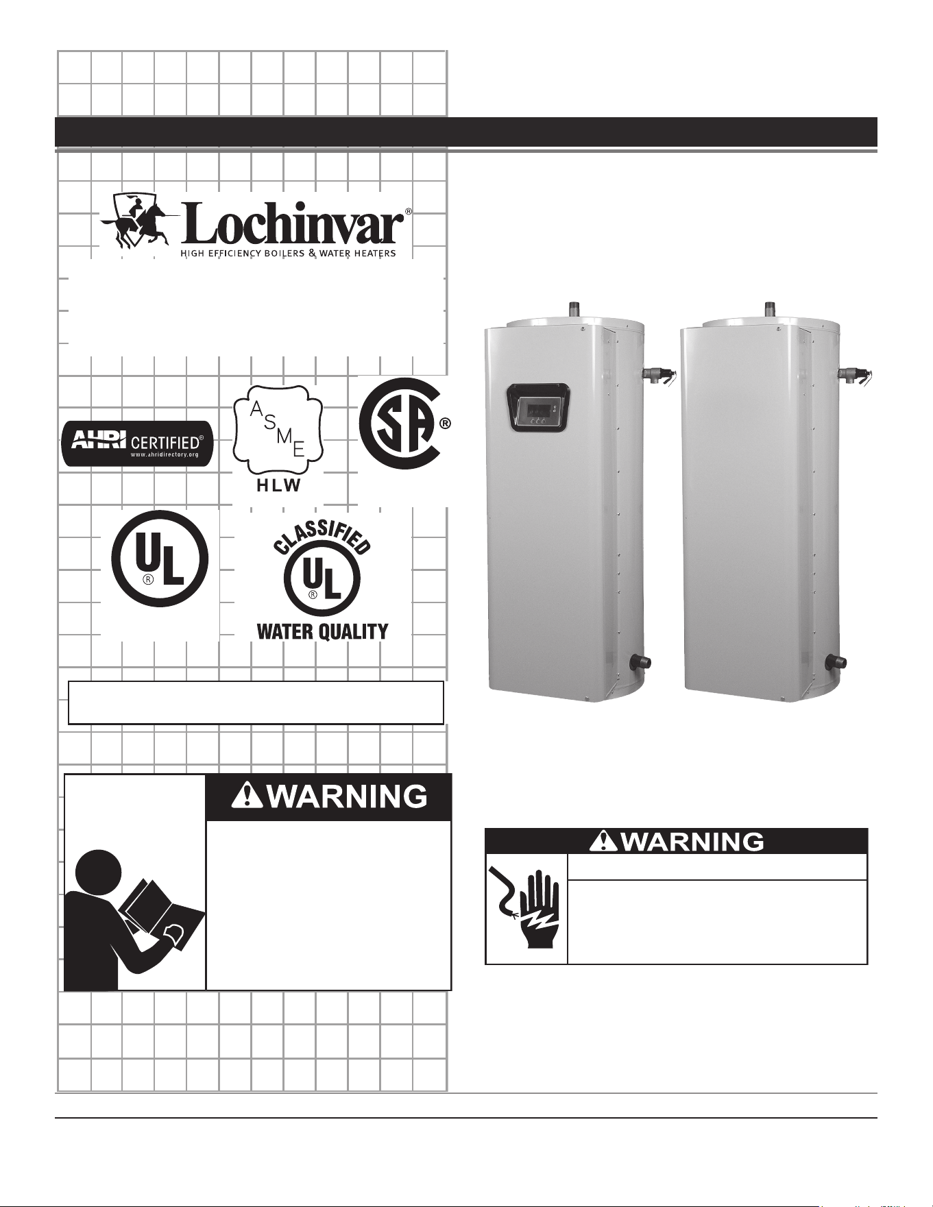
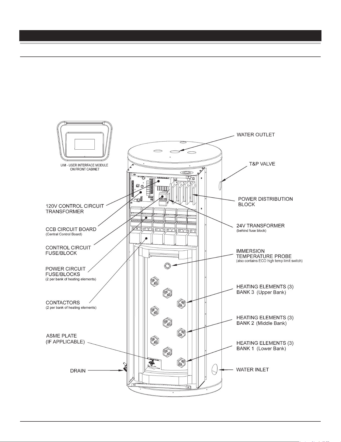
Figure 1. Electronic Control Models
Features and Components
Commercial Electric Water Heaters • 9
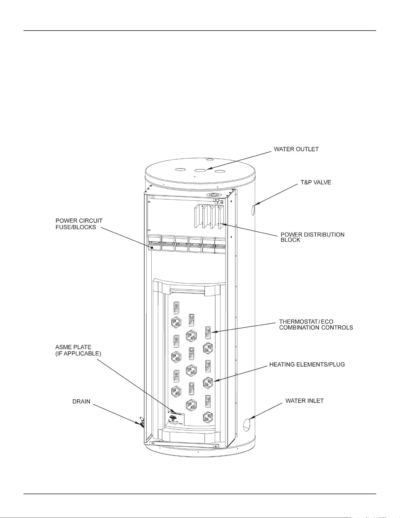
Figure 2. Surface Mount Control Models
10 • Commercial Electric Water Heaters
Features and Components
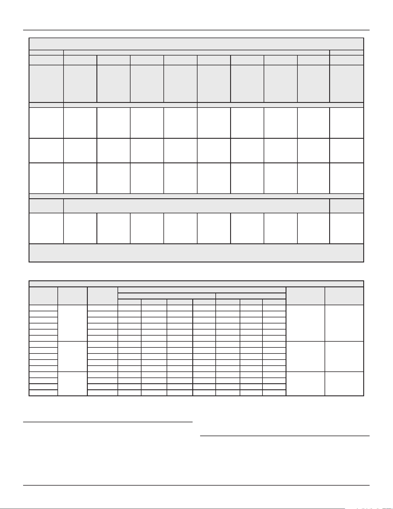
Table 1. Recovery Rate In Gallons Per Hour* / Temperature Rise °F
Standard
KW Input
BTU/
Hour 30° 40° 50° 60° 70° 80° 90° 100° 110° 120° 130° 140°
6 20,478 82 62 49 41 35 31 27 25 22 21 19 18
9 30,717 123 92 74 62 53 46 41 37 34 31 28 26
12 40,956 164 123 98 82 70 61 55 49 45 41 38 35
13.5 46,075 184 138 111 92 79 69 62 55 50 46 43 40
15 51,195 205 154 123 102 88 77 68 61 56 51 47 44
18 61,434 246 184 148 123 105 92 82 74 67 61 57 53
24 81,912 328 246 197 164 140 123 109 98 89 82 76 70
27 92,151 369 276 221 184 158 138 123 111 101 92 85 79
30 102,390 410 307 246 205 176 154 137 123 112 102 95 88
36 122,868 492 369 295 246 211 184 164 148 134 123 113 105
40.5 138,226 554 418 3332 277 237 208 1185 166 151 138 128 119
45 153,585 615 461 369 307 263 230 205 184 168 154 142 132
54 184,302 738 553 443 369 316 277 246 221 201 184 170 158
*Figured at 1 KW (3413 Btu) = 4.1 gallons at 100°F temperature rise.
To determine recovery rate per minute, divide recovery rate per hour by 60.
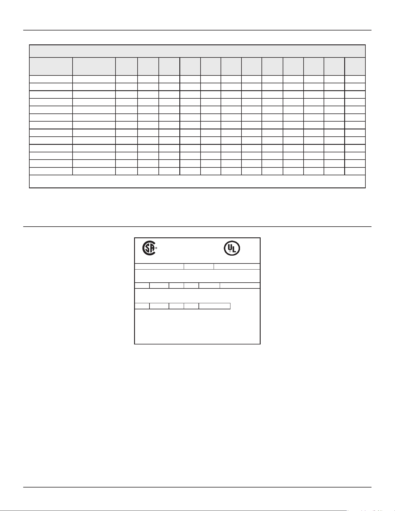
MODEL AND RATING PLATE
LISTED
22U1
No. OF
WATTS
PHASE VOLTS - AC ELEMENTS EACH
RATED MEASURED
%
WATTS
COMMERCIAL STORAGE
TANK WATER HEATER
MODEL NUMBER SERIAL NUMBER ITEM ID / PART NUMBER
WATTS
TOTAL
CAPACITY US GAL STANDBY LOSS MAX WORKING
PRESSURE
Low Lead Content
Commercial Electric Water Heaters • 11
INSTALLATION CONSIDERATIONS
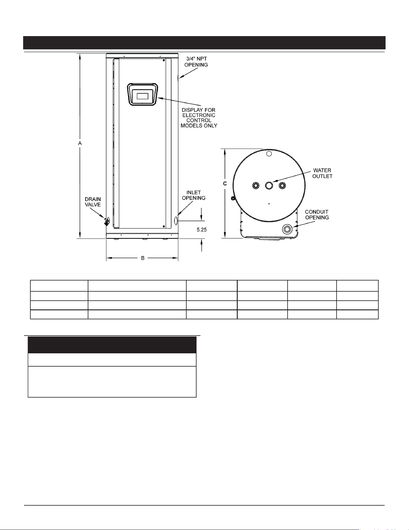
Figure 3. Rough-In Dimensions
Model Number Tank Capacity in Gallons (Liters) A - Inches (mm) B - Inches (mm) C - Inches (mm) Inlet/Outlet
LHS/LHC 50 50 (189.3) 55 3/4 (1416) 21 3/4 (552) 27 (685) 1 1/4
LHS/LHC 80 80 (302.8) 60 1/4 (1350) 25 1/2 (648) 31 (787) 1 1/4
LHS/LHC 119 119 (450.5) 62 1/4 (1581) 29 1/2 (749) 35 (889) 1 1/4
LOCATING THE WATER HEATER
Property Damage Hazard
•
All water heaters eventually leak.
•
Do not install without adequate drainage.
CAUTION
Carefully choose a location for the new water heater. The placement
is a very important consideration for the safety of the occupants in
the building and for the most economical use of the water heater.
Whether replacing an old water heater or putting the water heater in
a new location, the following critical points must be observed. The
water heater must be located:
• On a level surface. Shim the channel type skid base as
necessary if levelling is required.
• Near a oor drain. The heater should be located in an area
where leakage of the tank or connections will not result in
damage to the area adjacent to the heater or to lower oors of
the structure.
• Close to the point of major hot water usage and the power
supply.
• Hot water piping and branch circuit wiring should be as short
as possible.
• Insulate hot and cold water piping where heat loss and
condensation may be a problem.
• Heater construction permits installation, maintenance, and
service work to be
12 • Commercial Electric Water Heaters
INSTALLING THE WATER HEATER
The installation must conform with these instructions and the local
code authority having jurisdiction and the requirements of the power
company. In the absence of code requirements, follow NFPA-70
(current edition). In the absence of local codes, the installation must
comply with the latest editions of the National Electrical Code, NFPA
70 or the Canadian Electrical Code CSA C22.1. The National Electrical
Code may be ordered from: National Fire Protection Association, 1
Batterymarch Park, Quincy, MA 02269. The Canadian Electrical Code
is available from the Canadian Standards Association, 8501 East
Pleasant Valley Road, Cleveland, OH 44131.
Note: To comply with NSF Standard 5 installation requirements the
bottom of the water heater must be sealed to the oor with a
silicone based sealant or elevated 6 inches above the oor.
Do NOT test electrical system before heater is lled with water, follow
the procedures in Start Up and Operation (page 17).
The principal components of the heater are identied in Features and
Components (page 8).
Water temperature over 125°F (52°C)
can cause severe burns instantly
resulting in severe injury or death.
Children, the elderly and the
physically or mentally disabled are at
highest risk for scald injury.
Feel water before bathing or shower-
ing.
Temperature limiting devices such as
thermostatic point-of-use mixing
valves must be installed when
required by codes and to ensure safe
temperatures at fixtures.
REQUIRED ABILITY
Installation and service of this water heater requires ability equivalent
to that of a qualied agency (page 2) in the eld involved. See
Important Definitions (page 3). Plumbing and electrical work is
required.
THERMOSTATIC POINT-OF-USE MIXING VALVES
Water heaters are intended to produce hot water. Water heated to
a temperature which will satisfy space heating, clothes washing,
dish washing, cleaning and other sanitizing needs can scald and
permanently injure you upon contact. Some people are more likely
to be permanently injured by hot water than others. These include
the elderly, children, the infirm, or physically/developmentally
disabled. If anyone using hot water in your home ts into one of these
groups or if there is a local code or state law requiring a maximum
water temperature at the hot water tap, then you must take special
precautions.
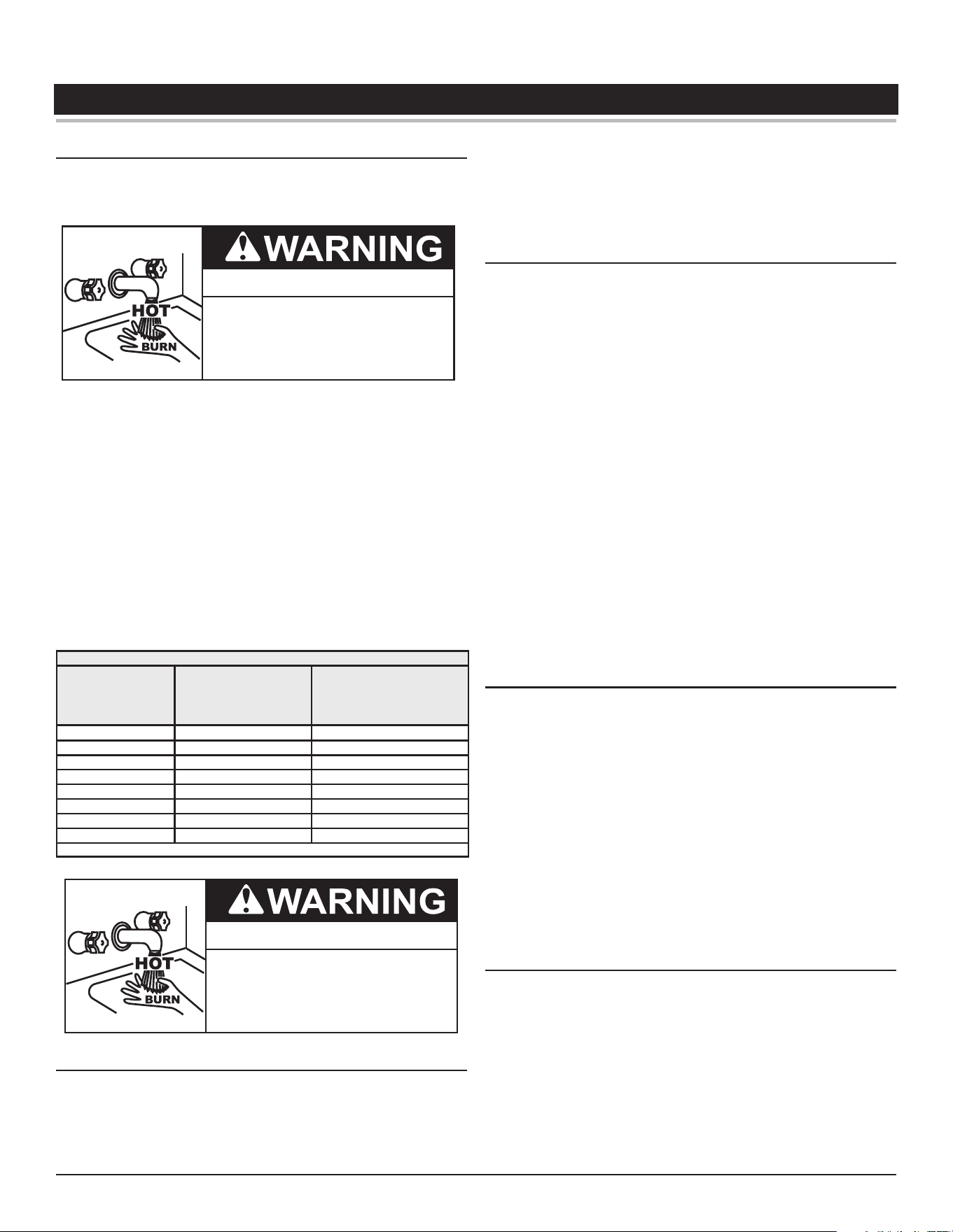
Table 2 shows the approximate time-to-burn relationship for normal
adult skin.
Table 2. Burn Time at Various Temperatures
Water Temperature
°F (°C)
Time for 1st Degree
Burn
(Less Severe Burns)
Time for Permanent
Burns
2nd & 3rd Degree
(Most Severe Burns)
110 (43) (normal shower temp.)
116 (47) (pain threshold)
116 (47) 35 minutes 45 minutes
122 (50) 1 minute 5 minutes
131 (55) 5 seconds 25 seconds
140 (60) 2 seconds 5 seconds
149 (65) 1 second 2 seconds
154 (68) instantaneous 1 second
(U.S. Government Memorandum, C.P.S.C., Peter L. Armstrong, Sept. 15, 1978)
Burn Hazard
If you choose a higher temperature
setting, install thermostatic mixing
valves at each point-of-use to help
avoid scalding.
Burn Hazard
To reduce the risk of unusually hot
water reaching the fixtures in the
house, install thermostatic mixing
valves at each point of use.
In addition to using the lowest possible temperature setting that
satises your hot water needs, a means such as a mixing valve
can be used at the water heater or the hot water taps used by
these people or at the water heater.
Check State and/or local codes for mixing valve requirements and
installation practices.
Thermostatic Point-of-Use Mixing Valves for reducing point of
use temperature are available. Consult a qualied installer or service
agency. Follow all manufacturer’s Instructions for installation of these
valves. Before changing the factory setting on the thermostat, read
Temperature Regulation (page 18).
Toxic Chemical Hazard
WARNING
● Do not connect to non-potable water system.
CONTAMINATED WATER
This water heater shall not be connected to any heating system(s)
or component(s) used with a non-potable water heating appliance.
Toxic chemicals, such as those used for boiler treatment shall not
be introduced into this system.
NOTICE
The water inlet and outlet threaded
connections are steel. When connecting the
unit to piping made of a different material, use of a dielectric fitting
or a dielectric union conforming to ASSE 1079 is recommended
to prevent corrosion and potential subsequent water leaks at or
near the connection. Dielectric fittings may be required by local
plumbing codes.
Installing the Water Heater
Commercial Electric Water Heaters • 13
Products of this sort should not be stored near the heater. Also, air
which is brought in contact with the water heater should not contain
any of these chemicals. If necessary, uncontaminated air should be
obtained from remote or outside sources.
CIRCULATING PUMP
Field installed circulating pumps should be of all bronze construction.
INSULATION BLANKETS
Insulation blankets are available to the general public for external
use on electric water heaters but are not necessary with this product.
The purpose of an insulation blanket is to reduce the standby heat
loss encountered with storage tank heaters. Your water heater meets
or exceeds the EPACT and ASHRAE/IES 90.1 standards with respect
to insulation and standby loss requirements, making an insulation
blanket unnecessary.
Should you choose to apply an insulation blanket to this heater,
you should follow these instructions below. Failure to follow these
instructions can result in re, serious personal injury, or death.
• Do not cover the temperature and pressure relief (T & P) valve
with an insulation blanket.
• Do not cover the instruction manual. Keep it on the side of the
water heater or nearby for future reference.
• Do obtain new warning and instruction labels for placement on
the blanket directly over the existing labels.
TEMPERATURE-PRESSURE RELIEF VALVE
Explosion Hazard
Temperature-Pressure Relief Valve
must comply with ANSI Z21.22-
CSA 4.4 and ASME code.
Properly sized temperature-
pressure relief valve must be
installed in opening provided.
Can result in overheating and
excessive tank pressure.
Can cause serious injury or death.
This water heater is provided with a properly rated/sized and certied
combination temperature - pressure relief valve by the manufacturer.
The valve is certied by a nationally recognized testing laboratory
that maintains periodic inspection of production of listed equipment
of materials as meeting the requirements for Relief Valves for Hot Water
Supply Systems, ANSI Z21.22 • CSA 4.4, and the code requirements of
ASME.
If replaced, the new valve must meet the requirements of local codes,
but not less than a combination temperature and pressure relief
valve rated/sized and certied as indicated in the above paragraph.
The new valve must be marked with a maximum set pressure not to
exceed the marked hydrostatic working pressure of the water heater
(150 psi = 1,035 kPa) and a discharge capacity not less than the
water heater Btu/hr or kW input rate as shown on the water heater’s
model rating plate.
For safe operation of the water heater, the temperature and pressure
relief valve must not be removed from its designated opening nor
plugged. The temperature-pressure relief valve must be installed
directly into the tting of the water heater designed for the relief
valve. Install discharge piping so that any discharge will exit only
within 6 inches (15.2 cm) above, or external to the structure. Do not
pipe the discharge to a crawl space. Be certain that no contact is
made with any live electrical part. The discharge opening must not
be blocked or reduced in size under any circumstances. Excessive
length, over 30 feet (9.14 m), or use of more than four elbows can
cause restriction and reduce the discharge capacity of the valve.
No valve or other obstruction is to be placed between the relief valve
and the tank. Do not connect discharge piping directly to the drain
unless a 6” (15.2 cm) air gap is provided. To prevent bodily injury,
hazard to life, or property damage, the relief valve must be allowed
to discharge water in adequate quantities should circumstances
demand. If the discharge pipe is not connected to a drain or other
suitable means, the water ow may cause property damage.
Property Damage Hazard
● The temperature-pressure relief-valve discharge pipe
must terminate at an adequate drain.
The Discharge Pipe:
• Shall not be smaller in size than the outlet pipe size of the
valve, or have any reducing couplings or other restrictions.
• Shall not be plugged or blocked.
• Shall not be exposed to freezing temperatures.
• Shall be of material listed for hot water distribution.
• Shall be installed so as to allow complete drainage of both the
Temperature-Pressure Relief Valve and the discharge pipe.
• Must terminate a maximum of six inches above a oor drain
or external to the building. In cold climates, it is recommended
that the discharge pipe be terminated at an adequate drain
inside the building.
Shall not have any valve or other obstruction between the relief valve
and the drain.
Water temperature over 125°F (52°C)
can cause severe burns instantly
resulting in severe injury or death.
Children, the elderly and the
physically or mentally disabled are at
highest risk for scald injury.
Feel water before bathing or shower-
ing.
Temperature limiting devices such as
thermostatic point-of-use mixing
valves must be installed when
required by codes and to ensure safe
temperatures at fixtures.
14 • Commercial Electric Water Heaters
Installing the Water Heater
The temperature-pressure relief valve must be manually operated
at least once a year. Caution should be taken to ensure that (1) no
one is in front of or around the outlet of the temperature-pressure
relief valve discharge line, and (2) the water manually discharged
will not cause any bodily injury or property damage because the
water may be extremely hot. If after manually operating the valve, it
fails to completely reset and continues to release water, immediately
close the cold water inlet to the water heater, follow the draining
instructions in this manual, and replace the temperature-pressure
relief valve with a properly rated/sized new one.
If you do not understand these instructions or have any questions
regarding the temperature-pressure relief valve call the toll free
number listed on the back cover of this manual for technical
assistance.
WATER LINE CONNECTIONS
This manual provides detailed piping installation diagrams. See
Piping Diagrams (page 49) for typical methods of application.
For the heater inlet and outlet connections, dielectric unions are
recommended. The water heater may be installed by itself, or with a
separate storage tank, on both single and two-temperature systems.
When used with a separate storage tank, the circulation may be either
by gravity or by means of a circulating pump. When a circulating
pump is used it is important to note that the ow rate should be
slow so that there will be a minimum of turbulence inside the heater.
CLOSED WATER SYSTEMS
Water supply systems may, because of code requirements or such
conditions as high line pressure, among others, have installed
devices such as pressure reducing valves, check valves, and back
ow preventers. Devices such as these cause the water system to
be a closed system.
THERMAL EXPANSION
As water is heated, it expands (thermal expansion). In a closed
system the volume of water will grow when it is heated. As the
volume of water grows there will be a corresponding increase in
water pressure due to thermal expansion. Thermal expansion can
cause premature tank failure (leakage). This type of failure is not
covered under the limited warranty. Thermal expansion can also
cause intermittent temperature-pressure relief valve operation:
water discharged from the valve due to excessive pressure build
up. This condition is not covered under the limited warranty. The
temperature-pressure relief valve is not intended for the constant
relief of thermal expansion.
A properly sized thermal expansion tank must be installed on all
closed systems to control the harmful eects of thermal expansion.
Contact a local plumbing service agency to have a thermal expansion
tank installed.
ELECTRICAL
Turn off power at the branch circuit
breaker serving the water heater
before performing any service.
Electrical Shock Hazard
•
Label all wires prior to disconnecting
when performing service. Wiring errors
can cause improper and dangerous
operation.
•
Verify proper operation after servicing.
•
Failure to follow these instructions can
result in personal injury or death.
•
The installation must conform with these instructions and the local
code authority having jurisdiction and the requirements of the power
company. In the absence of local codes, the installation must comply
with the current editions of the National Electrical Code, NFPA 70 or the
Canadian Electrical Code CSA C22.1.
An electrical ground is required to reduce risk of electrical shock
or possible electrocution. The water heater should be connected
to a separate grounded branch circuit with over-current protection
and disconnect switch. The water heater should be grounded in
accordance with national and local codes.
Voltage applied to the heater should not vary more than +5% to -10%
of the model and rating plate marking for satisfactory operation.
Table 3. Allowable Ampacities of Insulated Conductors
Not More Than Three Conductors in Raceway or Cable or Earth (Directly Buried), Based on Ambient Temperature of 30°C (86°F)
Size Temperature Rating of Conductor Size
60°C
(140°F)
75°C
(167°F)
85°C
(185°F)
90°C
(194°F)
60°C
(140°F)
75°C
(167°F)
85°C
(185°F)
90°C
(194°F)
AWG
MCM
TYPES
RUW, T
TW, UF
TYPES
FEPW
RH, RHW
RUH,
THW,
THWN,
XHHW
USE, ZW
TYPES
V, MI
TYPES
TA, TBS
SA, AVB
SIS, =FEP,
=FEPB,
=RHH,
=THHN,
=XHHW*
TYPES
RUW, T
TW, UF
TYPES
RH, RHW
RUH
THW,
THWN
XHHW,
USE
TYPES
V, MI
TYPES
TA, TBS,
SA, AVB
SIS,
=RHH,
=THHN,
=XHHW*
AWG
MCM
COPPER ALUMINUM OR COPPER-CLAD ALUMINUM
18
16
14
12
10
8
......
......
15
20
30
40
......
......
15
20
30
45
......
22
25
30
40
50
21
22
25
30
40
50
......
......
......
15
25
30
......
......
......
15
25
40
......
......
......
25
30
40
......
......
......
25
30
40
......
......
......
12
10
8
+ The load current rating and the overcurrent protection for these conductors shall not exceed 15 amperes for 14 AWG. 20 amperes for 12 AWG.
and 30 amperes for 10 AWG copper; or 15 amperes for 12 AWG and 25 amperes for 10 AWG aluminum and copper-clad aluminum.
* For dry locations only. See 75°C column for wet locations.
Installing the Water Heater
Commercial Electric Water Heaters • 15
Table 3. Allowable Ampacities of Insulated Conductors
Not More Than Three Conductors in Raceway or Cable or Earth (Directly Buried), Based on Ambient Temperature of 30°C (86°F)
Size Temperature Rating of Conductor Size
60°C
(140°F)
75°C
(167°F)
85°C
(185°F)
90°C
(194°F)
60°C
(140°F)
75°C
(167°F)
85°C
(185°F)
90°C
(194°F)
AWG
MCM
TYPES
RUW, T
TW, UF
TYPES
FEPW
RH, RHW
RUH,
THW,
THWN,
XHHW
USE, ZW
TYPES
V, MI
TYPES
TA, TBS
SA, AVB
SIS, =FEP,
=FEPB,
=RHH,
=THHN,
=XHHW*
TYPES
RUW, T
TW, UF
TYPES
RH, RHW
RUH
THW,
THWN
XHHW,
USE
TYPES
V, MI
TYPES
TA, TBS,
SA, AVB
SIS,
=RHH,
=THHN,
=XHHW*
AWG
MCM
COPPER ALUMINUM OR COPPER-CLAD ALUMINUM
6
4
3
2
1
55
70
80
65
85
100
115
130
70
90
105
120
140
70
90
105
120
140
40
55
65
75
50
65
75
90
100
55
70
80
95
110
55
70
80
95
110
6
4
3
2
1
0
00
000
0000
150
175
200
230
155
185
210
235
155
185
210
235
120
135
155
180
125
145
165
185
125
145
165
185
0
00
000
0000
250
300
350
400
500
255
285
310
335
380
270
300
325
360
405
270
300
325
360
405
205
230
250
270
310
215
240
260
290
330
215
240
260
290
330
250
300
350
400
500
CORRECTION FACTORS
Ambient
Temperature
°C
For ambient temperatures over 30°C, multiply the ampacities shown by the appropriate correction factor to deter-
mine the maximum allowable load current.
Ambient
Temperature
°F
31-40
41-50
51-60
61-70
71-80
.82
.58
......
......
......
.88
.75
.58
.35
......
.90
.80
.67
.52
.30
.91
.82
.71
.58
.41
.82
.58
......
......
......
.88
.75
.58
.35
......
.90
.80
.67
.52
.30
.91
.82
.71
.58
.41
86 –104
105–122
123–141
142–158
159–176
+ The load current rating and the overcurrent protection for these conductors shall not exceed 15 amperes for 14 AWG. 20 amperes for 12 AWG.
and 30 amperes for 10 AWG copper; or 15 amperes for 12 AWG and 25 amperes for 10 AWG aluminum and copper-clad aluminum.
* For dry locations only. See 75°C column for wet locations.
Table 4. Standard kW Inputs
KW
Input
Number Of
Elements
Element
wattage
Full Load Current In Amperes
Number ot
Thermostats
Number of
Fuses
Single Phase Three Phase
208V 240V 277V 480V 208V 240V 480V
6
3
2000 29 25 22 13 17 15 8
3 6
9 3000 44 38 33 19 25 22 11
12 4000 58 50 44 25 34 29 15
13.5 4500 65 57 49 29 38 33 17
15 5000 73 63 55 32 42 37 18
18 6000 - - - 75 65 38 - - - 44 22
18
6
3000 87 - - - - - - - - - 50 - - - - - -
6 12
24 4000 116 100 87 50 67 58 29
27 4500 130 113 98 57 75 65 33
30 5000 145 125 109 63 84 73 37
36 6000 - - - 150 130 75 - - - 87 44
36
9
4000 173 - - - - - - - - - 100 - - - - - -
9 18
40.5 4500 195 169 147 85 113 98 49
45 5000 217 188 163 94 125 109 55
54 6000 - - - 225 195 113 150 130 65
Amperage Table/Over-current Protection
The tables above provides the total connected heating element
load in amperes for branch circuit conductor and over-current
protection sizing. Single-phase heaters are two wire circuits. Three-
phase heaters are three wire circuits. In addition to the foregoing, a
grounded conductor is required.
The rating of the over-current protection must be computed on
the basis of 125% of the total connected load amperage. Where
the standard ratings and settings do not correspond with this
computation, the next higher standard rating or setting should be
selected.
Heater Circuits - Electronic Control Models
The water heater’s electrical components are pictured and identied
in Figure 1 (page 8) and Figure 2 (page 9). The model and
rating plate illustration on page 4 identies heater circuit ratings. The
electronic control model has two electrical circuits:

16 • Commercial Electric Water Heaters
Installing the Water Heater
• The control circuit, which controls the electrical power to
heating elements, referring the following control circuit diagram
Figure 12 (page 44).
• The power circuit, which is operated by the control circuit
carries the electrical load of the heating elements. The
following describes the heater circuits and includes wiring
diagrams for Delta conguration, refer to the WYE Conguration
Insert for water heaters operating at 380 V / 400 V / 416 V / 575
V. All heater circuits are designed for 50/60 cycle alternating
current.
Control Circuit - Electronic Control Models
These models are equipped with an electronic control system. The
system includes a CCB (Central Control Board), an immersion
temperature probe with ECO for temperature sensing and limiting, a
UIM (User Interface Module) for user interface & information display
and element current sensors for monitoring the power circuits. Refer
to the control circuit label on the water heater for details. The CCB
is powered by a small 120 V / 24 V transformer. The control circuit
operates on 120 V supplied by a larger 100 VA transformer. Standard
equipment includes control circuit fusing using two, 3 amp, class G
fuses with 600 volt rating. Do not substitute fuses of a dierent rating.
Sequence of Operation
1. When the control is powered, the UIM should display model
information, water temperature, Operating Set Point, heating
status and operating mode.
2. If the control determines that the actual water temperature inside
the tank is below the programmed Operating Setpoint minus the
(1st) dierential, a call for heat is activated.
3. After all safety checks are veried, the CCB will energize contactor
coils starting with the lower bank of heating elements (each
diagonal row of three heating elements is considered a “bank”)
then energize the middle bank (if so equipped) and top bank
(if so equipped). See Figure 1 (page 8). The middle and top
banks (if so equipped) are energized according to programmed
2nd and 3rd dierential set points.
4. The control remains in the heating mode until the water
temperature reaches the programmed Operating Setpoint. At
this point the contactors will be de-energized in the reverse order.
5. The control system now enters the standby operating mode
while continuing to monitor the water temperature and the state
of other system devices. If the water temperature drops below
the programmed Operating Setpoint minus the (1st) dierential,
the control will automatically return to step 2 and repeat the
heating cycle.
Note: See Set the Operating Set Point at the lowest setting which produces
an acceptable hot water supply. This will always give the most energy
efcient operation. (page 20) for more detailed information
on temperature settings mentioned above.
Commercial Electric Water Heaters • 17
START UP AND OPERATION
See Features and Components (page 8) for the location of
components mentioned in the instructions that follow.
NEVER turn on power to the water heater without being certain the
water heater is lled with water and a temperature and pressure
relief valve is installed in the relief valve opening.
DO NOT TEST ELECTRICAL SYSTEM BEFORE HEATER IS
FILLED WITH WATER. FOLLOW FILLING AND START-UP
INSTRUCTIONS IN OPERATION SECTION.
Full power is present whenever the
cabinet door is opened, even with
the pilot switch turned off.
Electrical Shock Hazard
FILLING THE WATER HEATER
Property Damage Hazard
To avoid water heater damage, fill tank with water
before operating.
CAUTION
1. Turn o the electrical disconnect switch.
2. Close the water heater drain valve.
3. Open a nearby hot water faucet to permit the air in the system
to escape.
4. Fully open the cold water inlet pipe valve allowing the heater and
piping to be lled.
5. Close the hot water faucet as water starts to ow. The heater is
now ready for STARTUP and TEMPERATURE REGULATION.
INITIAL START UP
The following checks should be made by the installer when the heater
is placed into operation for the rst time.
1. Turn o the electrical disconnect switch.
2. Open the front panel, check all water and electrical connections
for tightness. Also check connections on top and side of heater.
Repair water leaks and tighten electrical connections as
necessary.
3. Depress the red manual reset button on each Thermostat/ECO
combination control (Surface Mount Control Models only).
4. Turn on the electrical disconnect switch.
5. Observe the operation of the electrical components during the rst
heating cycle. Use care as the electrical circuits are energized.
6. Close the front panel.
Temperature control and contactor operation should be checked
by allowing heater to come up to temperature and shut off
automatically. Use care as the electrical circuits are energized.
18 • Commercial Electric Water Heaters
TEMPERATURE REGULATION
LIMITING THE RISK OF SCALDING
For a variety of reasons, water heaters can produce water that is
much hotter than its temperature setting. Take precautions to prevent
this higher temperature water from reaching the water xtures.
Burn Hazard
To reduce the risk of unusually hot
water reaching the fixtures in the
house, install thermostatic mixing
valves at each point of use.
According to a national standard , Performance Requirements for Water
Temperature Limiting Devices (ASSE 1070) and many local plumbing
codes, the water heater’s gas control valve should not be used as
the sole means to regulate water temperature and avoid scalds.
A properly adjusted thermostatic mixing valve at each point of use
allows you to set the tank temperature to a higher setting without
increasing risk of scalds. A higher temperature setting allows the
tank to provide much more hot water and can help provide proper
water temperatures for appliances such as dishwashers and washing
machines.
Table 5 shows the approximate time-to-burn relationship for normal
adult skin.
Table 5. Burn Time at Various Temperatures
Water Temperature
°F (°C)
Time for 1st Degree
Burn
(Less Severe Burns)
Time for Permanent
Burns
2nd & 3rd Degree
(Most Severe Burns)
110 (43) (normal shower temp.)
116 (47) (pain threshold)
116 (47) 35 minutes 45 minutes
122 (50) 1 minute 5 minutes
131 (55) 5 seconds 25 seconds
140 (60) 2 seconds 5 seconds
149 (65) 1 second 2 seconds
154 (68) instantaneous 1 second
(U.S. Government Memorandum, C.P.S.C., Peter L. Armstrong, Sept. 15, 1978)
Burn Hazard
If you choose a higher temperature
setting, install thermostatic mixing
valves at each point-of-use to help
avoid scalding.
HIGH TEMPERATURE LIMIT CONTROLS (ECO)
Both the ELECTRONIC CONTROL and SURFACE MOUNT
CONTROL model water heaters are equipped with one or more ECO
(energy cut out) non adjustable high temperature limit control(s).
An ECO is a normally closed switch that opens (activates) on a rise
in temperature. If the ECO switch contacts open (activate) due to
abnormally high water temperatures it will lock-out and disable further
heating element operation. It is important that a qualied service
agent be contacted to determine the reason for the ECO activation
before resetting the ECO. Once the reason has been determined
and corrected the ECO(s) can be reset as follows:
SURFACE MOUNT CONTROL MODELS
Surface Mount Control models have multiple surface mounted
Thermostat/ECO combination controls. One for each installed
heating element. See the surface mount control wiring diagrams
in Wiring Diagrams (page 43). The ECO high temperature limit
switch contacts on each control will open when the tank temperature
reaches approximately 200°F/93°C. When the ECO switch contacts
open (activate) voltage to ONE heating element ONLY is terminated
to prevent further heating operation of that element. Voltage may still
be present at other heating elements and they may still be heating
the water.
The ECO is a manual reset switch. Should one or more ECO activate,
the tank temperature must drop below 120°F/49°C before an ECO
can be reset. To manually reset an ECO:
1. Disconnect the power supply to the water heater.
2. Allow the tank temperature to cool below 120°F/49°C.
3. Remove the front control cover from the eected control(s).
4. Press the manual reset button on each of the eected controls.
Once the control(s) has been reset the control cover should be
replaced prior to restoring power to the water heater.
ELECTRONIC CONTROL MODELS
The ECO high temperature limit switch is located inside the
immersion Temperature Probe (two red wires) on ELECTRONIC
CONTROL models. The ECO switch contacts will open when the
water temperature reaches approximately 202°F/94°C. When the
ECO switch contacts open (activate) the electronic control system
locks out and displays a Fault message. Voltage to the contactor
coils and heating elements is terminated to prevent further heating
operation.
Should the ECO activate, the water temperature must drop below
140°F/60°C before the control system can be reset. Once the water
temperature has cooled below this point the power supply to the
water heater must be turned o and on again to reset the control
system.
THERMOSTAT CONTROLS
The water heaters covered in this instruction manual are equipped
with adjustable thermostat controls to control water temperature. Hot
water temperatures required for automatic dishwasher and laundry
use can cause scald burns resulting in serious personal injury and/
or death. The temperature at which injury occurs varies with the
person’s age and duration of exposure. The slower response time
of children, the elderly or disabled persons increases the hazards to
them. Never allow small children to use a hot water tap or draw their
own bath water. Never leave a child or disabled person unattended
in a bathtub or shower.
Temperature Regulation
Commercial Electric Water Heaters • 19
The water heater should be located in an area where the general
public does not have access to set temperatures.
Burn Hazard
If you choose a higher temperature
setting, install thermostatic mixing
valves at each point-of-use to help
avoid scalding.
Setting the water heater temperatures at 120°F will reduce the risk of
scalds. Some States require settings at specic lower temperatures.
THERMOSTAT SETTINGS - SURFACE MOUNT CONTROL
Water temperature over 125°F (52°C)
can cause severe burns instantly
resulting in severe injury or death.
Children, the elderly and the
physically or mentally disabled are at
highest risk for scald injury.
Feel water before bathing or shower-
ing.
Temperature limiting devices such as
thermostatic point-of-use mixing
valves must be installed when
required by codes and to ensure safe
temperatures at fixtures.
These models have multiple thermostat/ECO combination controls
one for each heating element installed. These thermostats are set
from the factory at 140°F/60°C. Set the thermostat dial at the lowest
setting which produces an acceptable hot water supply. This will
always give the most energy ecient operation.
The water heater is supplied with thermostats that may come from
dierent manufactures and have dierent temperature indications
as described below.
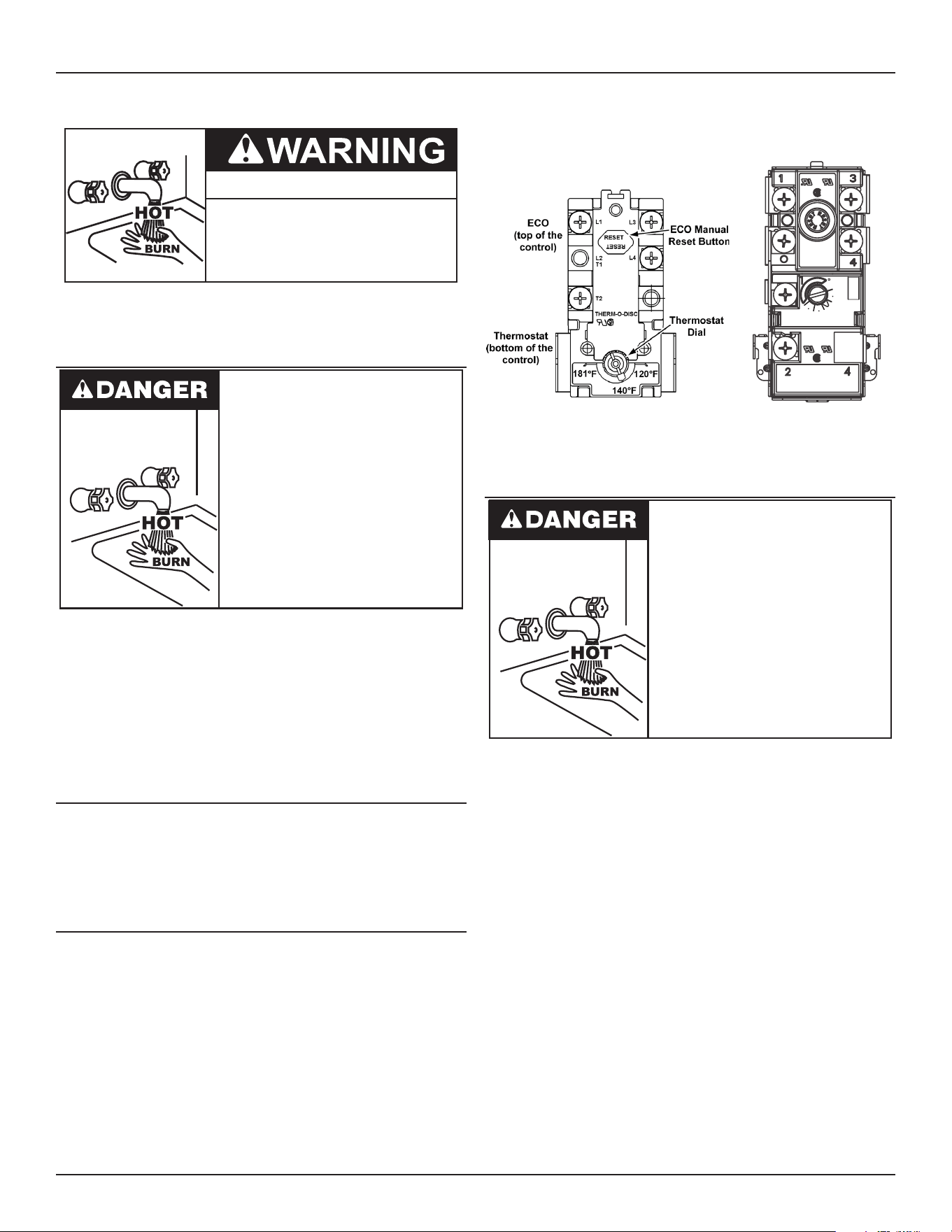
Thermodisc Thermostat
Thermodisc thermostats are adjustable from approximately 120°F
(49°C) (lowest setting) to 181°F (83°C) (highest setting). See
Figure 4 (page 19). These thermostats are set from the factory at
approximately the 140°F (60°C) setting. The over temperature device
(ECO high limit) attached to each thermostat has a manual reset.
APCOM Thermostat
Apcom thermostats have three designated set points; LO, MED and
HI. The approximate equivalent temperatures for these three settings
are: LO = 140°F (60°C), MED = 160°F (71°C) and HI = 181°F (83°C).
These thermostats are set from the factory at the MED 140°F (60°C)
setting. The over temperature device (ECO high limit) attached to
each thermostat has a manual reset. See Figure 4 (page 19).
Thermodisc Thermostat
APCOM
INC
40A 120-277 VAC
25A.480 VAC
125VA.PT.DTY.
120-480 VAC
MED
LO
HI
MODEL
WH19HC
30A 120-250 VAC
22A 277 VAC
12.5A 480VAC
125 VA.PT.DTY. 120-480 VAC
APCOM Thermostat
Figure 4. Thermostatic Disc and APCOM Thermostats
THERMOSTAT SETTINGS - ELECTRONIC CONTROLS
Water temperature over 125°F (52°C)
can cause severe burns instantly
resulting in severe injury or death.
Children, the elderly and the
physically or mentally disabled are at
highest risk for scald injury.
Feel water before bathing or shower-
ing.
Temperature limiting devices such as
thermostatic point-of-use mixing
valves must be installed when
required by codes and to ensure safe
temperatures at fixtures.
These models are equipped with an electronic control system.
The control system senses temperature from a factory installed
Immersion Temperature Probe. See Figure 1 (page 8). The
“Operating Set Point” is adjusted to control water temperature. This
is an adjustable user setting in the control system’s Temperatures
menu. This and all control system menus are accessed through the
user interface module (UIM) located on the front panel of the water
heater. See Figure 5.
The Operating Set Point is adjustable from 90°F/42°C to 190°F/88°C.
The factory setting is 120°F/49°C. See Set the Operating Set Point at
the lowest setting which produces an acceptable hot water supply. This
will always give the most energy efficient operation. (page 20) for
instructions on how to adjust the Operating Set Point and other
user settings.
20 • Commercial Electric Water Heaters
Temperature Regulation
Figure 5. User Interface Module (UIM)
Set the Operating Set Point at the lowest setting which produces an
acceptable hot water supply. This will always give the most energy
ecient operation.
Commercial Electric Water Heaters • 21
CONTROL SYSTEM OPERATION
Control System Features
Advanced Diagnostics: Plain English text and animated icons
display detailed operational and diagnostic information. LCD screen
on the front of the water heater displays the Sequence of Operation
in real time. Fault or Alert messages are displayed when operational
problems occur. Advanced Service menu displays a list of possible
causes for current Fault and Alert conditions to aid in servicing.
Economy Mode Operation: Control system automatically lowers
the Operating Set Point by a programmed value during user dened
time periods. Helps reduce operating costs during unoccupied or
peak demand periods.
Linear Sequencing: Banks of heating elements (3 elements per
bank) are energized according to adjustable (1 to 20°) dierential
set points for each bank. First bank on is the last bank o. Helps
reduce operating costs during low/moderate loads.
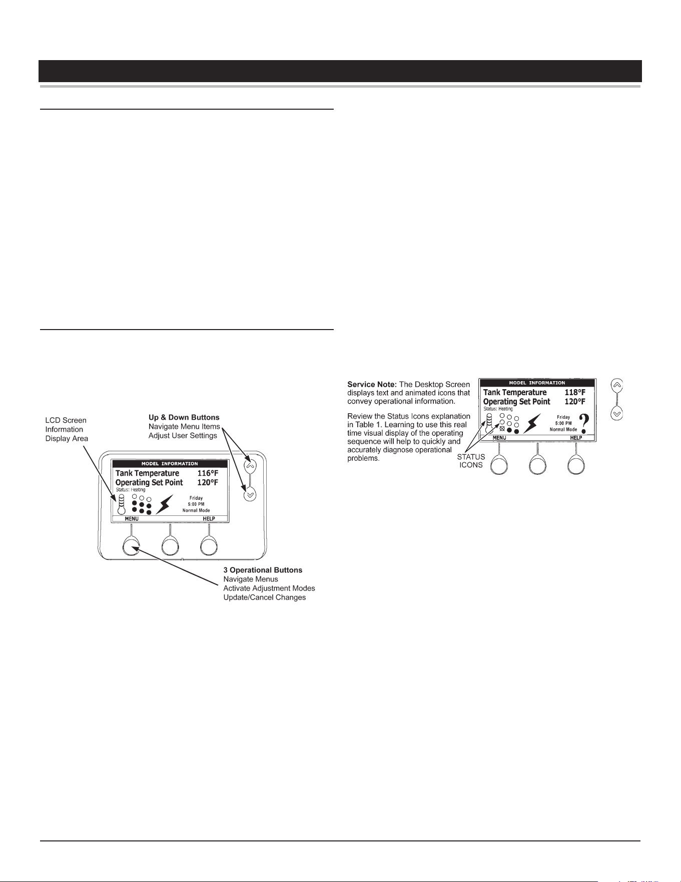
Control System Navigation
The UIM (User Interface Module) is located on the front cabinet of the
Electronic Control Model water heaters. All operational information
and user settings are displayed and accessed using the UIM. The
UIM includes ve snap acting (momentary) user input buttons; an
Up, Down and 3 Operational Buttons.
Figure 6. User Interface Module (UIM)
Up & Down Buttons
Used to navigate (up and down) and to select (highlight) menu items.
Also used to adjust or change (increase/decrease, on/o, set time)
various user settings.
Operational Buttons
The 3 Operational Buttons are multifunctional. Their current function
is dened by the text that appears above each button on the LCD
screen. The function will change depending on what menu is currently
displayed or what menu item is selected. When no text appears on
the LCD screen above an Operational Button there is no function
assigned.
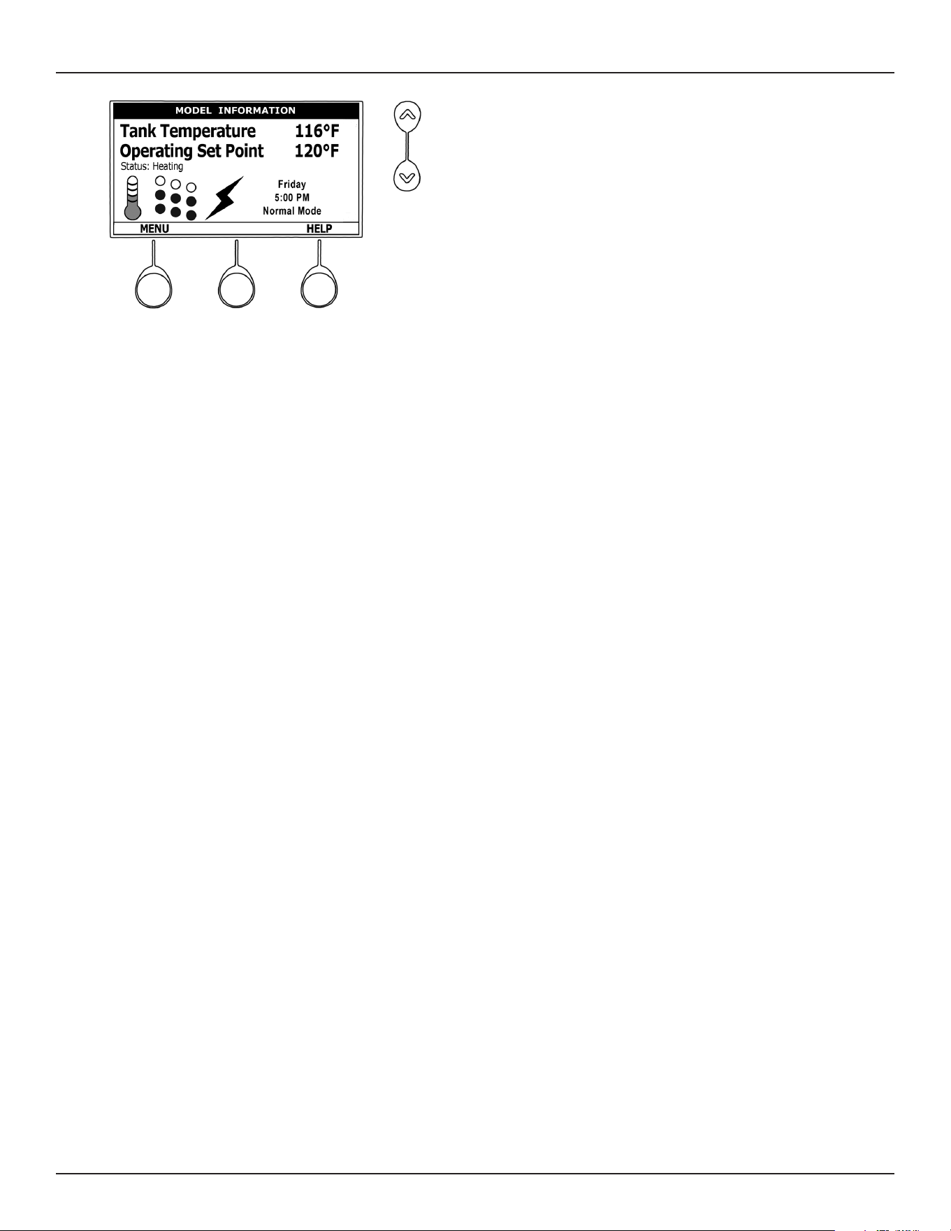
The Home Screen
Figure 7. Home Screen below shows the control system Home
Screen. This is the default screen. If there are no active Fault or
Alert conditions and no user input for approximately 10 minutes the
control system will return to this screen automatically.
Model Information
Model information and menu titles are shown in the black bar at the
top of the Home Screen.
Tank Temperature
Current water temperature as sensed from the immersion
Temperature Probe.
Operating Set Point: Temperature at which the control system will
maintain tank (water) temperature in the Normal Mode. This line of
text will read Economy Set Point whenever the control system is
operating in the Economy Mode.
Status: The Operating State of the control system is displayed
beneath the Operating Set Point.
Figure 7. Home Screen
Menu: The left Operational Button is pressed to enter the Main Menu
where all control system menus are accessed. See Table 8 (page
23) for a list of control system menus.
Help: The right Operational Button is pressed to access instructions
and explanations for user settings, Operating States, Status Icons,
manufacturer’s web address, technical support phone number and
service agent contact information.
Day/Time/Operating Mode: The current time and day are also
displayed on the Home Screen. “Clock Not Set” will be displayed
until the time clock has been initially set. Day and Time are adjusted
in the Economy Mode Setup menu. The current Operating Mode,
either Normal Mode or Economy Mode, is displayed beneath the
day and time.
Discreet Menu Contact Information: From the Home Screen
press and hold down the middle (unmarked) Operational Button for
30 seconds and then release it. This will launch a discreet menu
where personalized contact information can be entered. Installing
contractors and/or service agents can enter their company name
and telephone number. This contact information will be displayed
with all Fault and Alert messages.
22 • Commercial Electric Water Heaters
Control System Operation
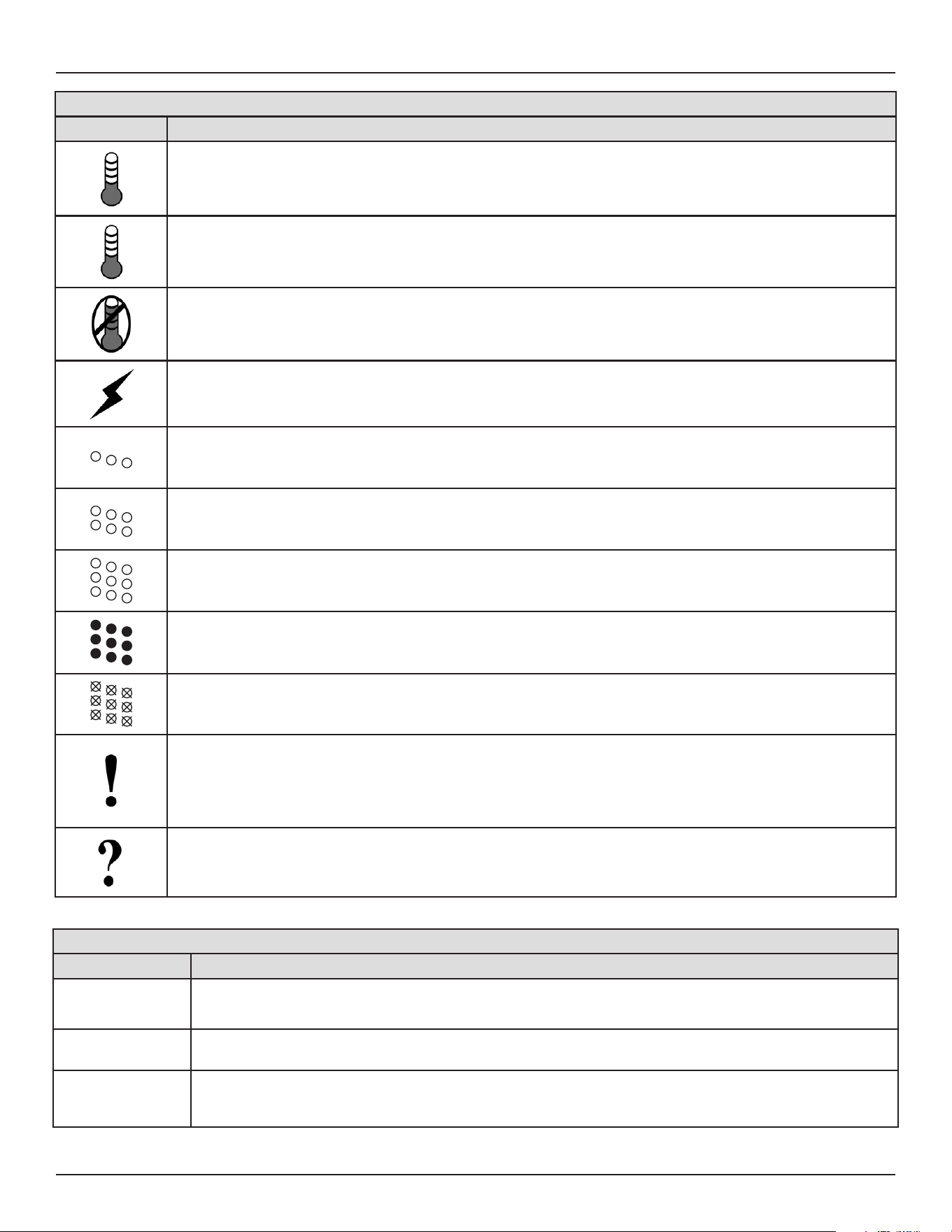
Table 6. Status Icons
ICON DESCRIPTION
Water temperature in the tank has fallen. Shaded area of the animated thermometer icon will rise and fall in response
to water temperature in the storage tank as sensed from the immersion Temperature Probe.
Water temperature in the tank has reached the Operating Set Point. Shaded area of the animated thermometer icon will
rise and fall in response to water temperature in the storage tank as sensed from the immersion Temperature Probe.
The control is unable to initiate a heating cycle. This will happen whenever a Fault condition is detected by the control
system or when either of the two Enable/Disable circuits are open circuits.
The control system is in Heating Mode and has energized the electromagnetic contactor coils for at least one bank of
heating elements. This animated icon DOES NOT indicate current has been sensed from the heating elements, only
that there is a call for heat present and the control system has initiated heating operation.
Heating elements icon for a water heater equipped with 1 Bank of heating elements. Each circle represents one heating
element. Each diagonal row of 3 elements = 1 Bank of elements. Open circles represent heating elements the control
system has not energized and is not sensing electrical current from.
Heating elements icon for a water heater equipped with 2 Banks of heating elements. Each circle represents one
heating element. Each diagonal row of 3 elements = 1 Bank of elements. Open circles represent heating elements
the control system has not energized and is not sensing electrical current from.
Heating elements icon for a water heater equipped with 3 Banks of heating elements. Each circle represents one
heating element. Each diagonal row of 3 elements = 1 Bank of elements. Filled circles represent heating elements
the control system has energized AND is sensing electrical current from.
Heating elements icon for a water heater equipped with 3 Banks of heating elements. Each circle represents one
heating element. Each diagonal row of 3 elements = 1 Bank of elements. Open circles with an X represent heating
elements the control system has energized that it IS NOT sensing electrical current from.
The control has detected/declared a Fault Condition. Fault message details can be viewed in the Current Fault menu.
Heating operation is discontinued (locked out) until the condition that caused the fault is corrected. Power to the water
heater must be cycled o and on to reset the control system.
Note: Cycling power will not reset the control system if the condition that caused the fault has not been corrected.
The control has detected/declared an Alert Condition. The water heater will continue to operate during an Alert Condition
but there is an operational condition that requires the attention of a Qualied Service Agent. Alert message details can
be viewed in the Current Alert menu.
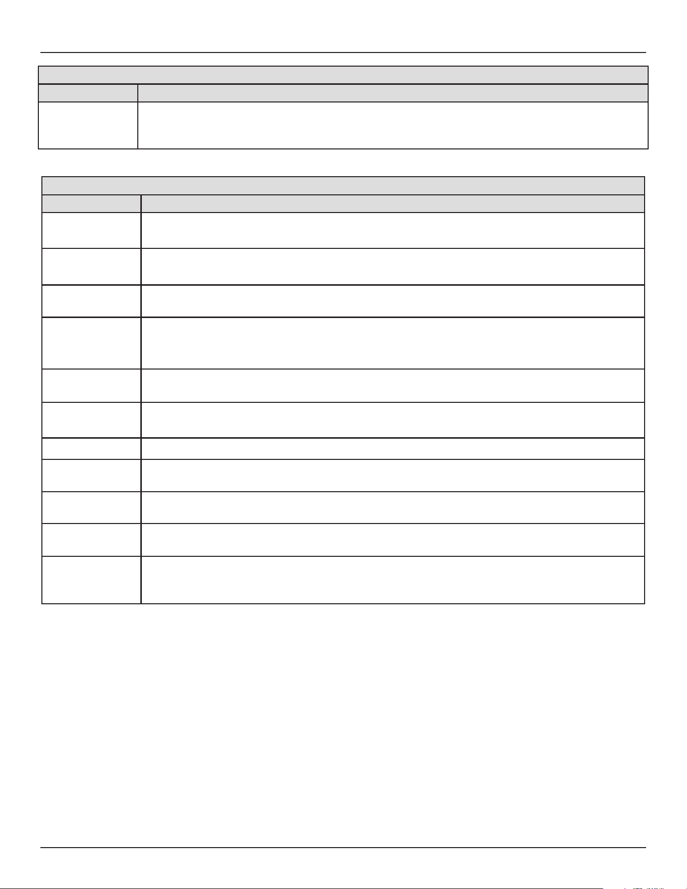
Table 7. Operating States
STATE DESCRIPTION
Standby
The water heater is not in an active heating cycle. This usually indicates the temperature in the tank has reached the Operat-
ing Set Point and the control system has terminated the heating cycle.
Heating The control system is in the Heating Mode. At least one bank of heating elements has been energized.
Alert
The control system has detected/declared an Alert Condition. The controls system will continue heating operation. However, a
Qualied Service Agent should be contacted to check/service the water heater.
Control System Operation
Commercial Electric Water Heaters • 23
Table 7. Operating States
STATE DESCRIPTION
Fault
The control system has detected/declared a Fault Condition. The control system will discontinue heating operation and “lock
out.” Power to the water heater must be cycled o and on to reset the control system. Note; cycling power will not reset the
control system until the condition that caused the fault has been corrected.
Table 8. Control System Menus
MENUS DESCRIPTION
Temperatures
Most commonly accessed menu. Operating Set Point, Dierential settings, Tank Temperature and Tank Probe Oset are
located in this menu.
Heater Status
Current Operating State/Mode (heating/standby etc) and status (open/closed - on/o - yes/no) of monitored water heater
functions and components are displayed in this menu.
Economy Mode
Setup
Seven day 24 hour time clock with temperature set back capability to reduce operating costs during unoccupied or reduced
demand periods.
Alarm Output
Setup
The control system’s CCB (Central Control Board) features on board SPDT (single pole double throw) relay contacts for
building EMS (Energy Management System) notication of operational conditions such as Fault Conditions and heating
mode status. This menu features a list of user denable conditions for relay activation.
Display Settings
Temperature units (°F or °C), appearance (brightness contrast) and backlight delay user adjustable settings are located in
this menu.
Heater Information
Elapsed time of operation, total heating cycle time, heating cycle count, heating element bank(s) cycle count and heating
bank on time along with UIM and CCB software revisions can be viewed in this menu.
Current Fault/Alert Displays any current Alert or Fault messages.
Fault History
Retains 9 event history of Fault/Alert messages with time stamp. The Fault History is useful when dealing with intermittent
operational problems or when the customer has reset the control system prior to a service agent’s arrival.
Fault Occurrence
Running total of all Fault and Alert Conditions that have occurred are displayed in this menu. Can help determine potential
root cause(s) of related operational problems.
Restore Factory
Defaults
This control system feature allows the user to restore control system user settings to their factory default settings. Alarm
Output Setup and Display Settings menu items ARE NOT changed when factory defaults are restored.
Help Menu
Accessible by pressing the corresponding Operational Button from most menus and screen displays. This menu provides
access to instructions and explanations for user settings, Operating States, Status Icons, manufacturer’s web address, tech-
nical support phone number and service agent contact information.
24 • Commercial Electric Water Heaters
Control System Operation
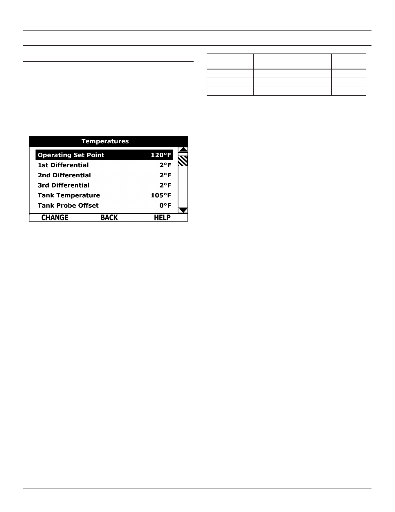
TEMPERATURES MENU
Operating Set Point
User adjustable setting 90°F to 190°F range; factory default is
120°F. When the water temperature sensed by the control system
from the immersion Temperature Probe reaches the Operating Set
Point the control system will end the heating cycle. A call for heat
will be activated again when the water temperature drops below the
Operating Set Point minus the 1st Dierential Setting.
Example: Operating Set Point is 120°F, the 1st Dierential Setting is
2°F (factory default). A call for heat will be activated when the sensed
water temperature drops to 118°F.
Dierential Settings
Adjustable user setting(s) 1°F to 20° range; factory default is 2°F.
The water heaters covered in this Instruction Manual will have 3,
6 or 9 heating elements. Each group of 3 heating elements is one
“Bank” of heating elements. Heating elements are energized in
Banks of 3. Each Bank of heating elements will have a Dierential
Setting associated with it. Dierential Settings are located in the
Temperatures Menu.
There is a 1st Dierential Setting on all models. There will be one
additional Dierential Setting visible/adjustable for each additional
Bank of (3) heating elements.
Operating Sequence
With an Operating Set Point of 120°F and all Dierential settings at 2°F
the On/O sequencing of heating element Banks would be as follows:
BANK NUMBER
DIFFERENTIAL
SETTING
TURN ON
TEMP
TURN OFF
TEMP
Bank 1 2°F 118°F 120°F
Bank 2 2°F 116°F 118°F
Bank 3 2°F 114°F 116°F
Tank Temperature
Non adjustable information display. Current water temperature as
sensed by the control system from the immersion Temperature
Probe.
Tank Probe Oset
User adjustable setting -5°F to +5°F range; factory default is 0°F.
If the current Tank Temperature is sensed (from the immersion
Temperature Probe) at 120°F and the oset is adjusted to -5°F the
control system would calibrate or “oset” the Tank Temperature to
115°F. Heating cycles would then start/stop based on the calibrated
Tank Temperature.
Used to calibrate for slight dierences in control system temperature
sensing. This can improve the precision of temperature control in
the storage tank and at points of use. This feature can also be used
to compensate for building recirculation loops (hot water returning
to the storage tank) that may cause the heating cycle to terminate
prematurely.
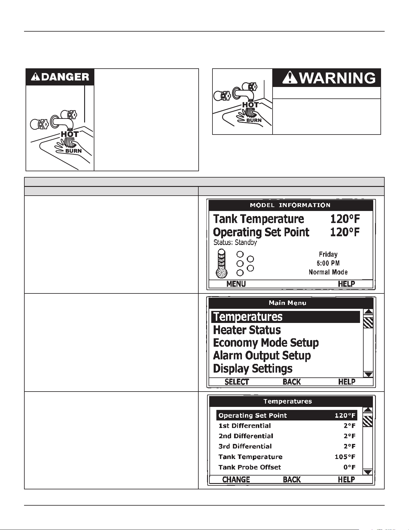
Control System Operation
Commercial Electric Water Heaters • 25
Temperature Settings
The Operating Set Point and the Dierential Settings are adjusted in the Temperatures Menu. The following instructions explain how to
adjust these user settings and navigate the control system menus.
Water temperature over 125°F (52°C)
can cause severe burns instantly
resulting in severe injury or death.
Children, the elderly and the
physically or mentally disabled are at
highest risk for scald injury.
Feel water before bathing or shower-
ing.
Temperature limiting devices such as
thermostatic point-of-use mixing
valves must be installed when
required by codes and to ensure safe
temperatures at fixtures.
Burn Hazard
If you choose a higher temperature
setting, install thermostatic mixing
valves at each point-of-use to help
avoid scalding.
Adjusting the Operating Set Point and the Differential Settings
ACTION DISPLAY
From the Home Screen, press the Operational Button underneath
“MENU” to enter the Main Menu.
Notice how the text above the Operational Buttons on the display
changes as you navigate through the various menus and screens.
With Temperatures selected (highlight in black) in the Main Menu,
press the Operational Button underneath “SELECT” to enter the Tem-
perature Menu.
If Temperatures is not selected use the Up and Down buttons to select
this menu item.
With the Operating Set Point selected (highlighted in black) in the Tem-
peratures Menu, press the Operational Button underneath “CHANGE”
to activate the adjustment mode for this menu item.
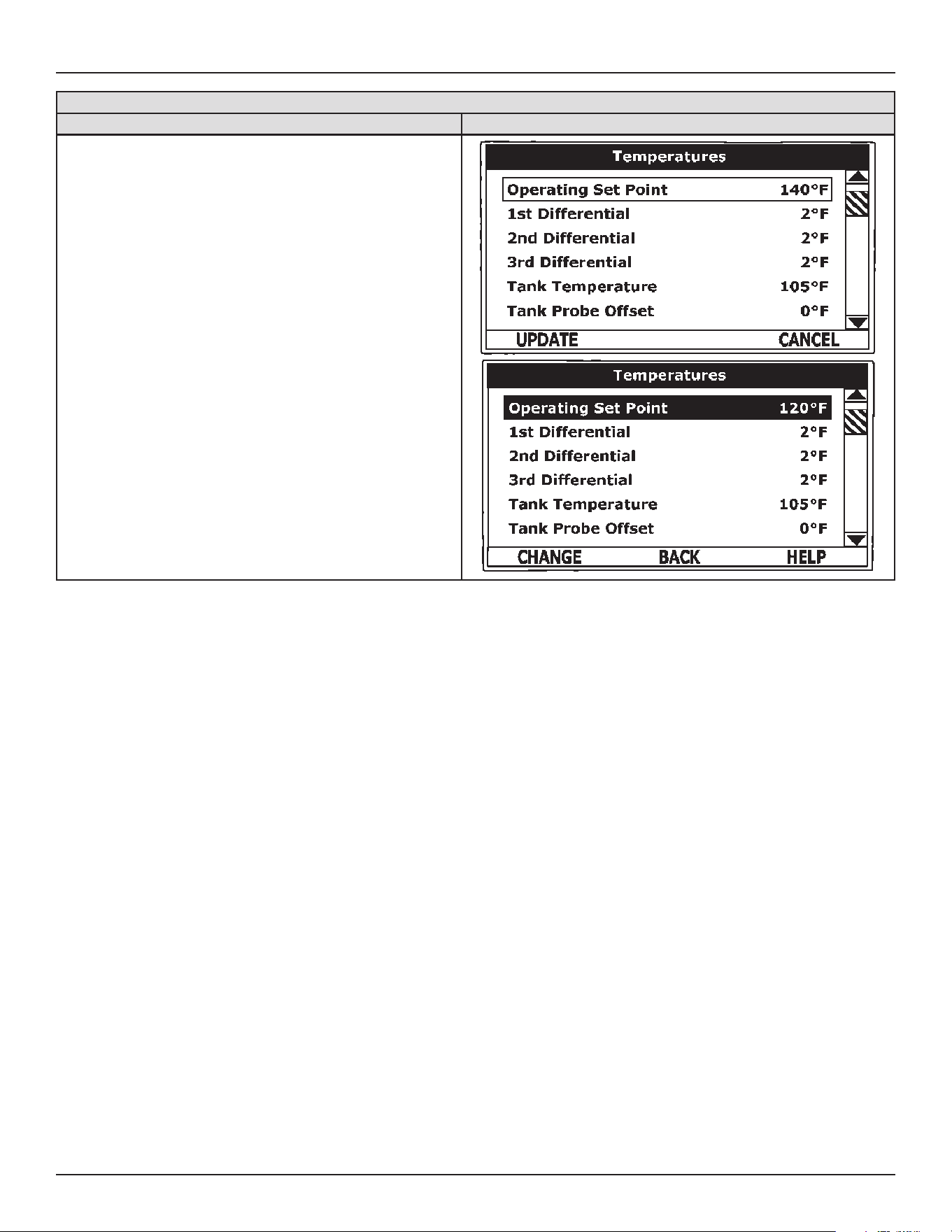
26 • Commercial Electric Water Heaters
Control System Operation
Adjusting the Operating Set Point and the Differential Settings
ACTION DISPLAY
Press the Up and Down buttons to adjust the Operating Set Point to
the desired setting.
Press the Operational Button underneath “UPDATE” to conrm the new
setting. Press the Operational Button underneath “CANCEL” to discard
the new setting and retain the previous setting.
The new Operating Set Point value should now be displayed as the
current value.
NOTE: Use this same procedure to adjust the Dierential settings and
the Tank Probe Oset in the Temperatures Menu.
This same procedure is used to change user settings in other control
system menus.
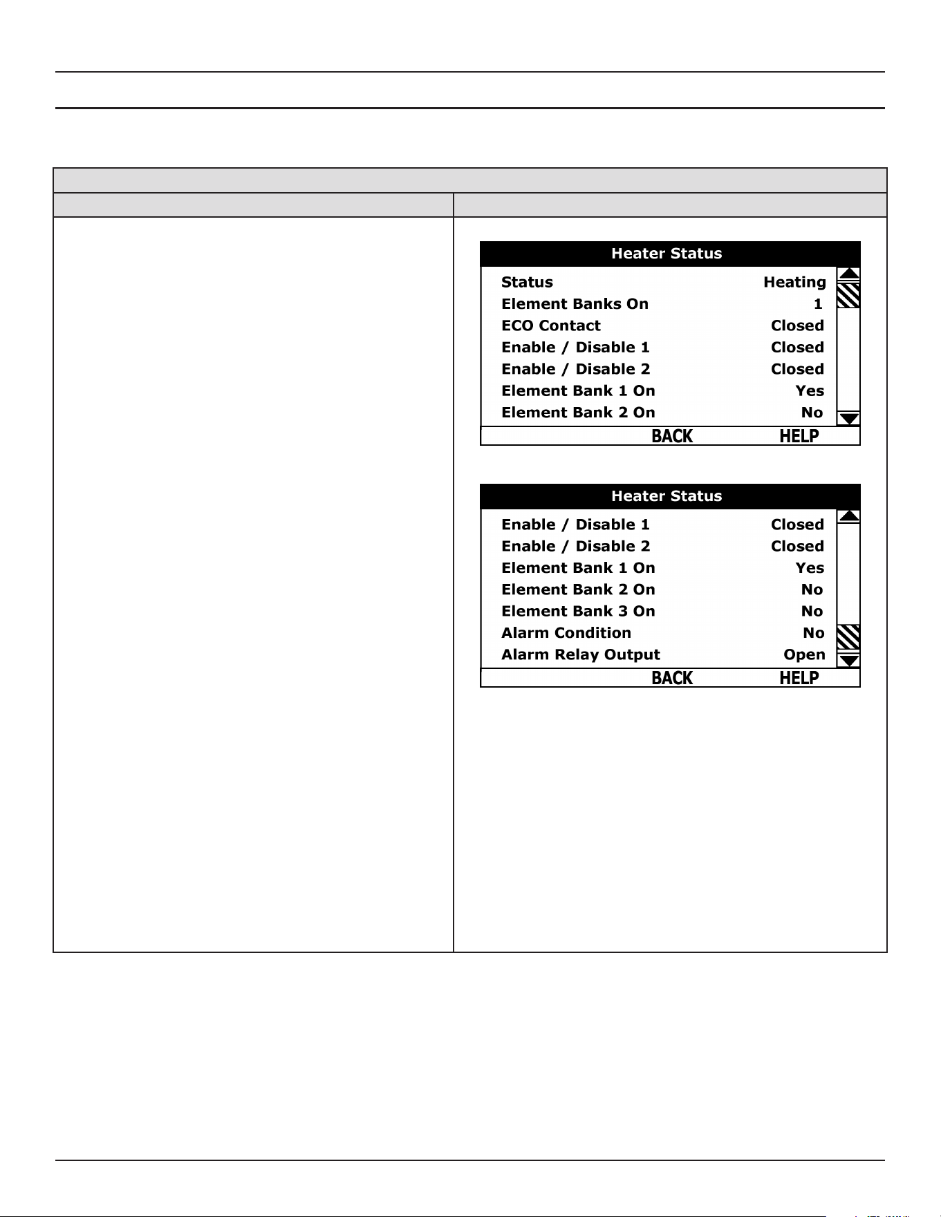
Control System Operation
Commercial Electric Water Heaters • 27
HEATER STATUS MENU
This menu displays non adjustable operational information. This menu contains more information that can be displayed on one screen of
the LCD display. Use the Up & Down Buttons to navigate to the bottom of this menu.
Heater Status Menu
ACTION DISPLAY
Status Displays the current Operating State of the control
system, for example, Heating, Standby, or Fault. See Table 7
(page 22).
Element Banks On Displays the current number of heating
element Banks the control system has energized. Each Bank
of elements contains 3 heating elements.
ECO Contact - Displays the current state of the ECO high
temperature limit switch contacts. The ECO switch is located
inside the immersion Temperature Probe (two red wires).
Enable / Disable 1 & 2 - Displays the current state, open
or closed, of the two Enable/Disable circuits (J7 socket on
the CCB) provided for external supervisory controls such
as building EMS (Energy Management System). See Wiring
Diagrams (page 43). Both of these Enable/Disable circuits
must be closed to “enable” heating operation. If either Enable/
Disable circuit is open for any reason heating operation will be
“disabled.” There is a plug with two jumper wires installed from
the factory in the CCB J7 socket to enable heating operation
when external controls are not in use.
Service Note: If a supervisory control(s) is used to enable/
disable heating operation, install eld wiring between the J7
socket on the CCB and a set of “dry contacts” on the external
control per all applicable building codes. This is a switching
circuit only: DO NOT apply any external voltage or connect
any load (for example, relay coil) to either circuit.
Element Bank On - Displays the on/o status of each Bank
of heating elements. Yes = On, No = O.
Alarm Condition - Displays the status of the user denable
Alarm Output function. See Alarm Output Setup Menu (page 34).
Yes = alarm condition has been met, No = alarm condition has
not been met.
Alarm Relay Output - Displays the state of the normally open
contacts of the Alarm Output relay. This relay (J3 contacts
on the CCB) is used for building EMS (Energy Management
System) notication of operational conditions such as Fault
conditions.
Top of Menu
Bottom of Menu
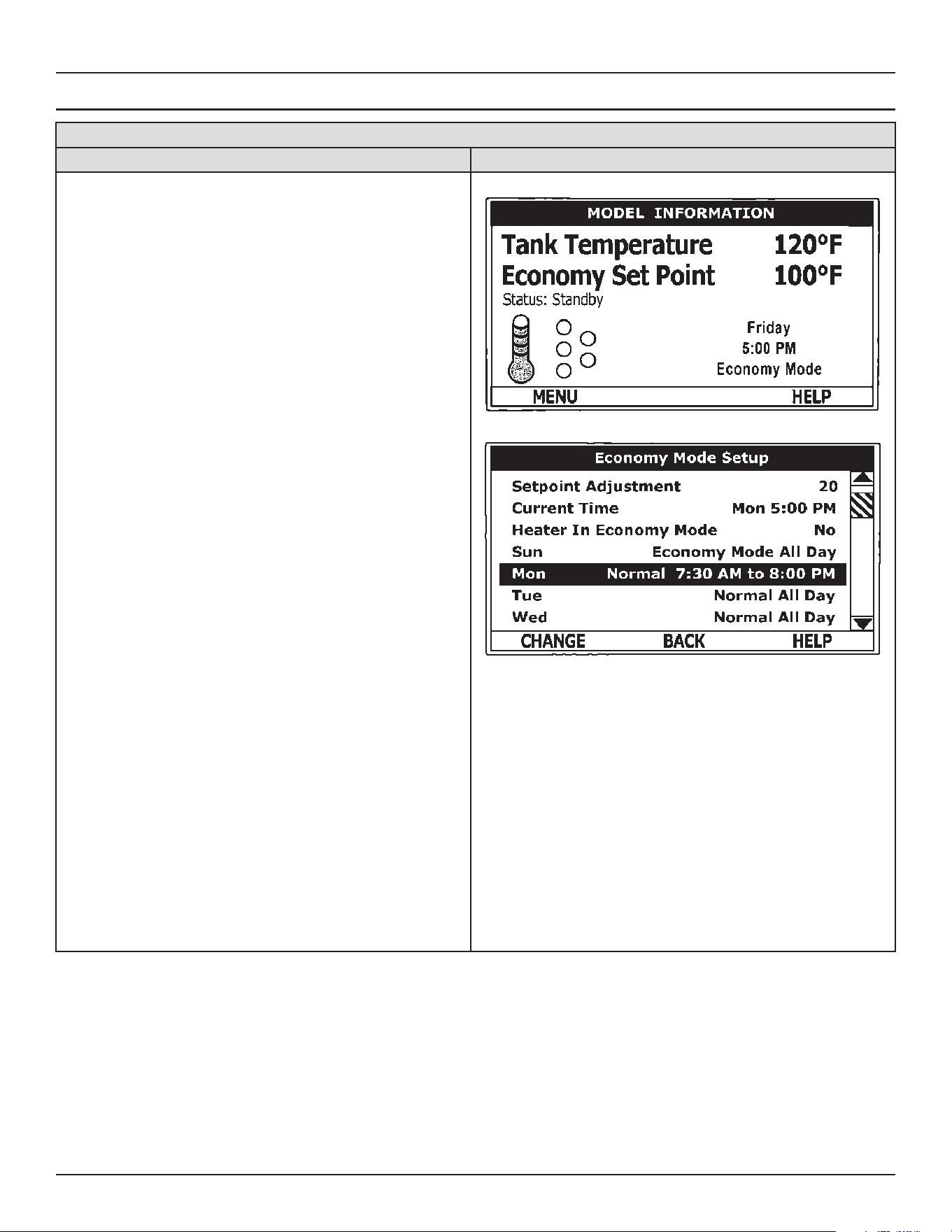
28 • Commercial Electric Water Heaters
Control System Operation
ECONOMY MODE SETUP MENU
Economy Mode Home Screen and Setup Menu
ACTION DISPLAY
This menu contains settings used to establish an “Economy
Set Point” and “Economy Mode” operating periods. This
control system feature can help reduce operating costs during
unoccupied, low load, or peak demand periods.
Set-Point Adjustment - Adjustable user setting (2°F to 50°F -
factory default is 20°F) the control system uses to calculate the
“Economy Set Point.” The Economy Set Point = normal Operating
Set Point minus the programmed Set-Point Adjustment value.
The Economy Set Point is the water temperature the control
system maintains during programmed Economy Mode time
periods. “Economy Set Point” is displayed instead of “Operating
Set Point” and “Economy Mode” appears beneath the current
time on the Home Screen during Economy Mode time periods.
Current Time - Seven Day 24 hr clock. Use this menu item
to set the current time and day of the week. Current day and
time are not set from the factory. “Clock Not Set” will be dis-
played on the Home until the time/day has been initially set.
Note: the time will not self adjust for Daylight Savings time.
Heater In Economy Mode - Displays whether the control system
is currently operating in Economy Mode or not.
Daily Operating Mode (Sun - Mon - Tue - Wed - Thu - Fri - Sat)
- Seven daily sub menus are listed at the bottom of the Economy
Mode Setup menu. There are 3 Operating Modes in each sub
menu; “Normal Operation All Day” - “Economy Mode All Day”
and “Normal Operation Between.” Only one Operating Mode
can be active, the factory default is Normal Operation All Day.
Normal Operation All Day: When this operating mode is active
the normal Operating Set Point is used for the entire day.
Economy Mode All Day: When this operating mode is active
the Economy Set Point is used for the entire day.
Normal Operation Between: When this operating mode is
active there will also be start and stop times to program. The
normal Operating Set Point is used between the programmed
start and stop times and the Economy Set Point will be in eect
during the rest of the day. There is one start time and one stop
time event per day.
Home Screen During Economy Mode
Economy Mode Setup Menu
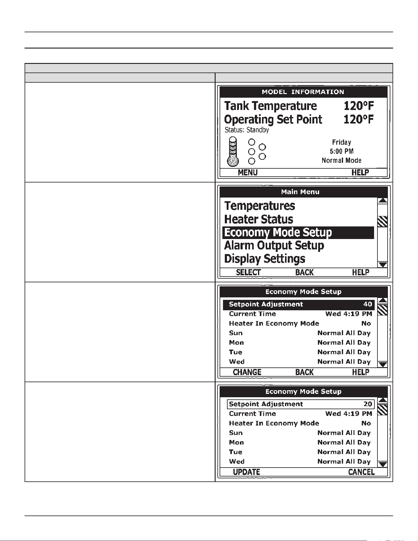
Control System Operation
Commercial Electric Water Heaters • 29
ECONOMY MODE SETTINGS
Set- Point Adjustment Value
ACTION DISPLAY
From the Home Screen, press the Operational Button underneath “MENU”
to enter the Main Menu.
Notice how the text above the Operational Buttons on the display changes
as you navigate through the various menus and screens.
Use the Up/Down buttons to select (highlight in black) the Economy Mode
Setup menu from the Main Menu. Press the Operational Button underneath
“SELECT” to enter the Economy Mode Setup menu.
Use the Up/Down buttons to select (highlight in black) Set-Point Adjustment.
Press the Operational Button underneath “CHANGE” to activate the adjust-
ment mode for the Set-Point Adjustment value.
Use the Up/Down buttons to change the Set-Point Adjustment to the desired
value. The Set-Point Adjustment value is adjustable from 2°F to 50°F. The
factory default is 20°F.
Notice how the text above the Operational Buttons on the display changes
to “UPDATE” & “CANCEL” when the adjustment mode is activated and how
the current value is outlined rather than highlighted in black.
Press the Operational Button underneath “UPDATE” to enter and conrm
the new value. Pressing the Operational Button underneath “CANCEL”
would discard the new value and retain the previous value.
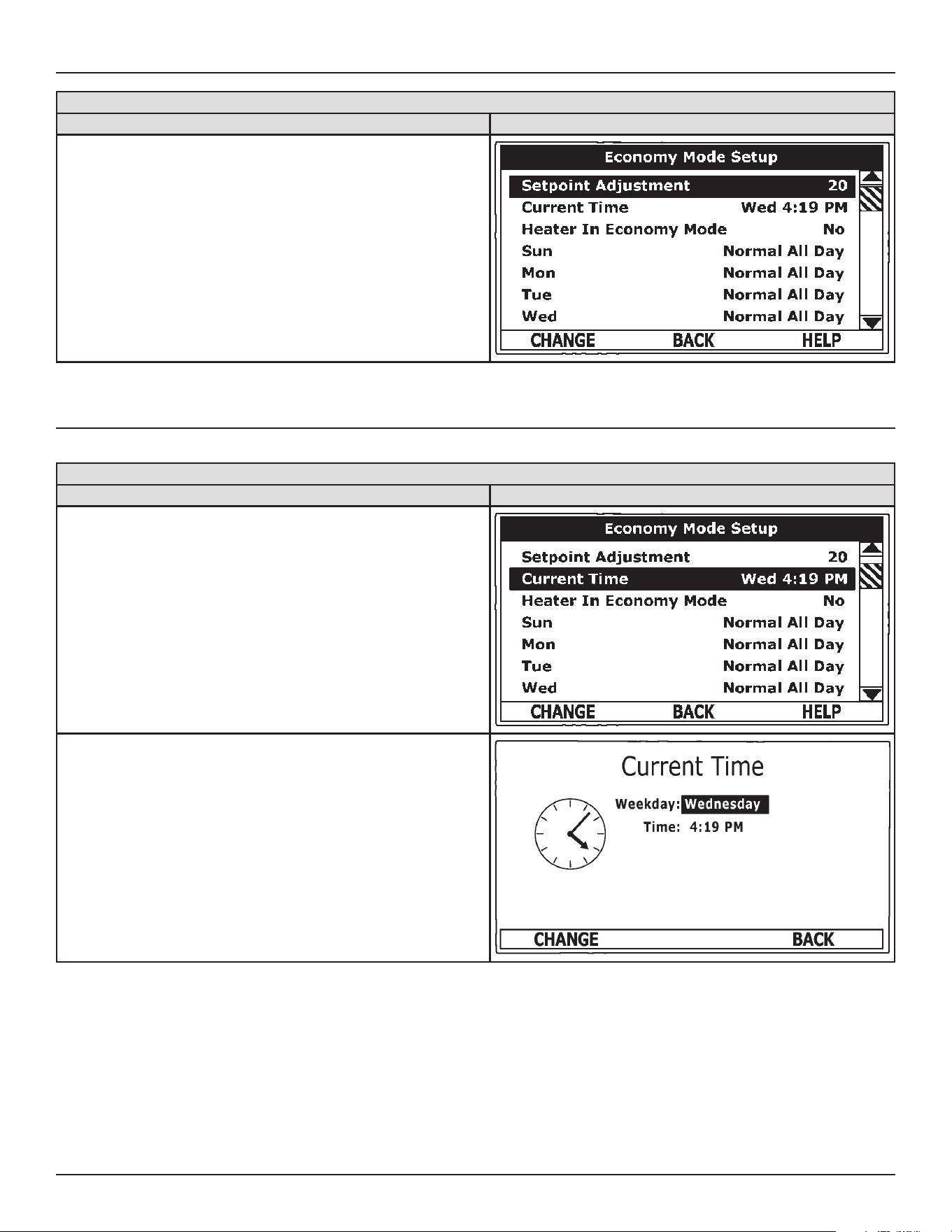
30 • Commercial Electric Water Heaters
Control System Operation
Set- Point Adjustment Value
ACTION DISPLAY
The new Set-Point Adjustment value should now be displayed as the current
value.
TIME CLOCK SETTINGS
Time Clock Settings
ACTION DISPLAY
From the Home Screen navigate to the Economy Mode Setup menu.
Use the Up/Down buttons to select (highlight in black) Current Time sub
menu. Press the Operational Button underneath “CHANGE” to enter the
Current Time sub menu.
Use the Up/Down buttons to select the “Weekday” setting.
Press the Operational Button underneath “CHANGE” to activate the adjust-
ment mode for this setting.
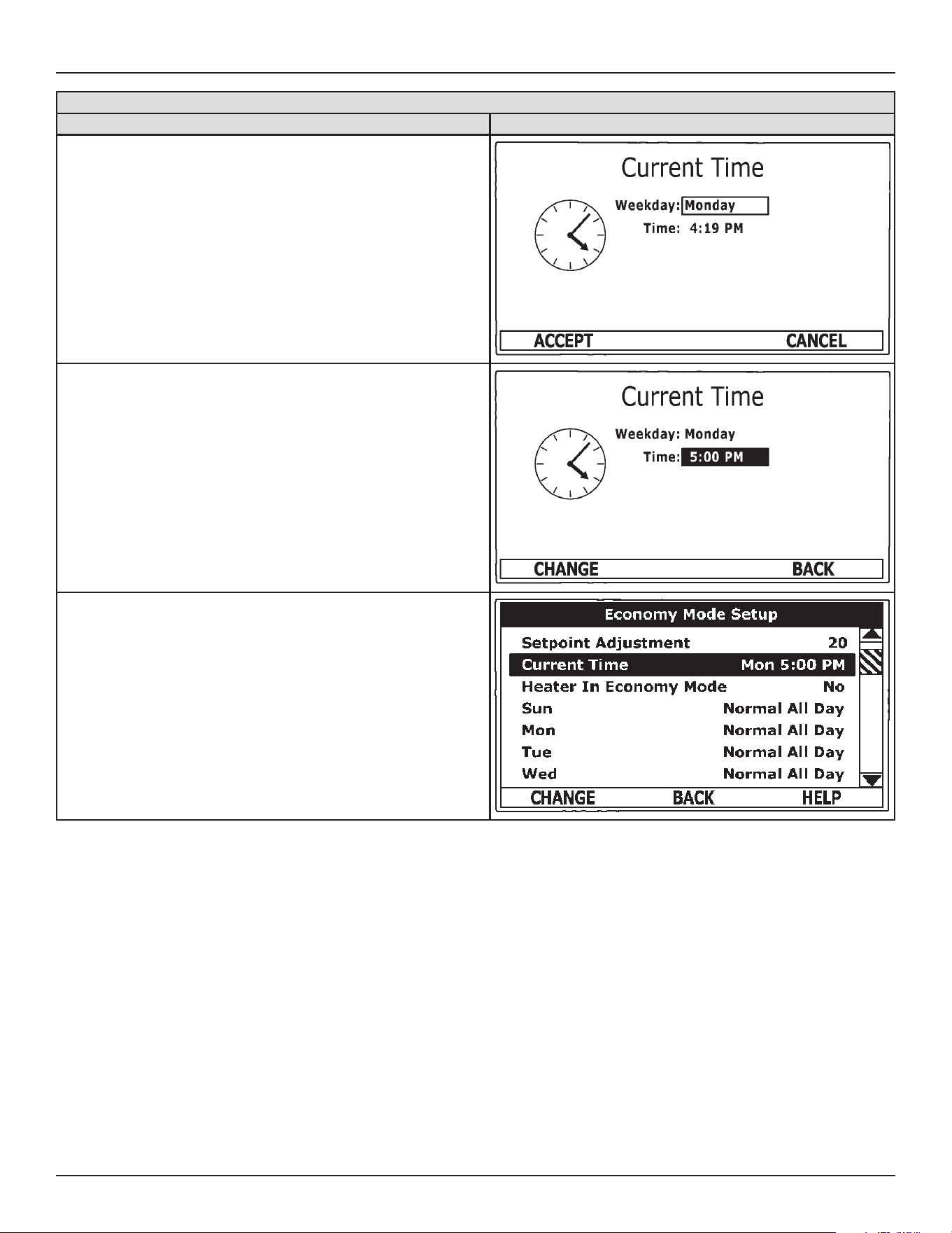
Control System Operation
Commercial Electric Water Heaters • 31
Time Clock Settings
ACTION DISPLAY
Press the Up and Down buttons to adjust the Weekday setting to the current
day.
Notice how the text above the Operational Buttons on the display changes
to “ACCEPT” & “CANCEL” when the adjustment mode is activated and how
the current setting is outlined rather than highlighted in black.
Press the Operational Button underneath “ACCEPT” to enter and conrm
the new setting. Pressing the Operational Button underneath “CANCEL”
would discard the new setting and retain the previous setting.
Use the Up/Down and the CHANGE/ACCEPT Operational Buttons to indi-
vidually select and change the remaining time settings (Hour, Minutes, AM/
PM) to the current time in the same way as outlined above.
When nished making changes press the Operational Button underneath
“BACK” to conrm all new settings and update the control system. The dis-
play will automatically return to the Economy Mode Setup menu.
The new settings should be displayed as the Current Time.
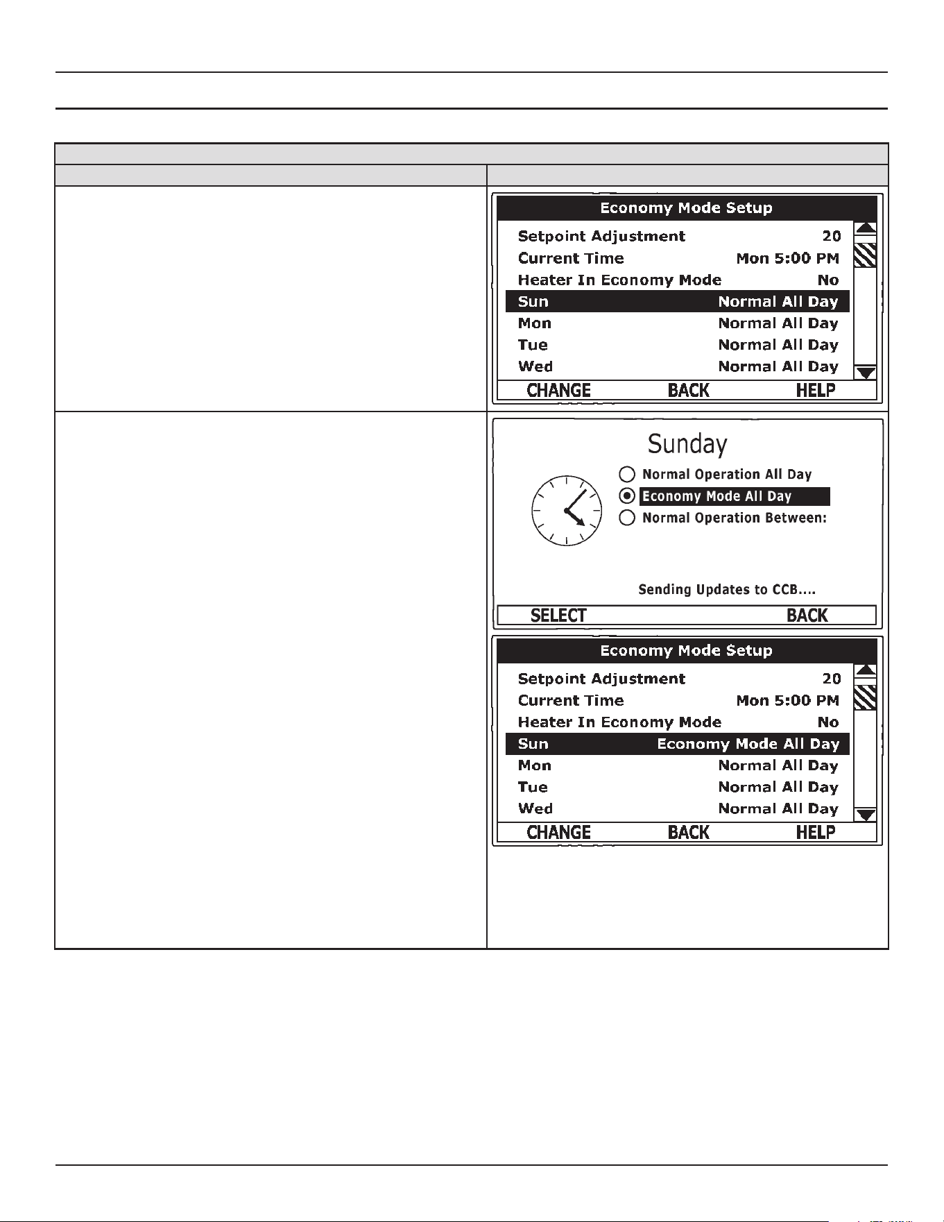
32 • Commercial Electric Water Heaters
Control System Operation
DAILY OPERATING MODE SETTINGS
Daily Operating Mode Settings
ACTION DISPLAY
Economy Mode All Day:
From the Economy Mode Setup menu use the Up/Down buttons to select
(highlight in black) the Daily sub menu for “Sun.” Press the Operational But-
ton underneath “CHANGE” to enter this menu.
Use the Up/Down buttons to select (highlight in black) the “Economy Mode
All Day” setting.
Press the Operational Button underneath “SELECT” to change from the fac-
tory default Normal Operation All Day setting to the Economy Mode All Day
setting.
Press the Operational Button underneath “BACK” to conrm the new setting
and update the control system. You will be returned to the Economy Mode
Setup menu. The new setting should now be displayed for Sun.
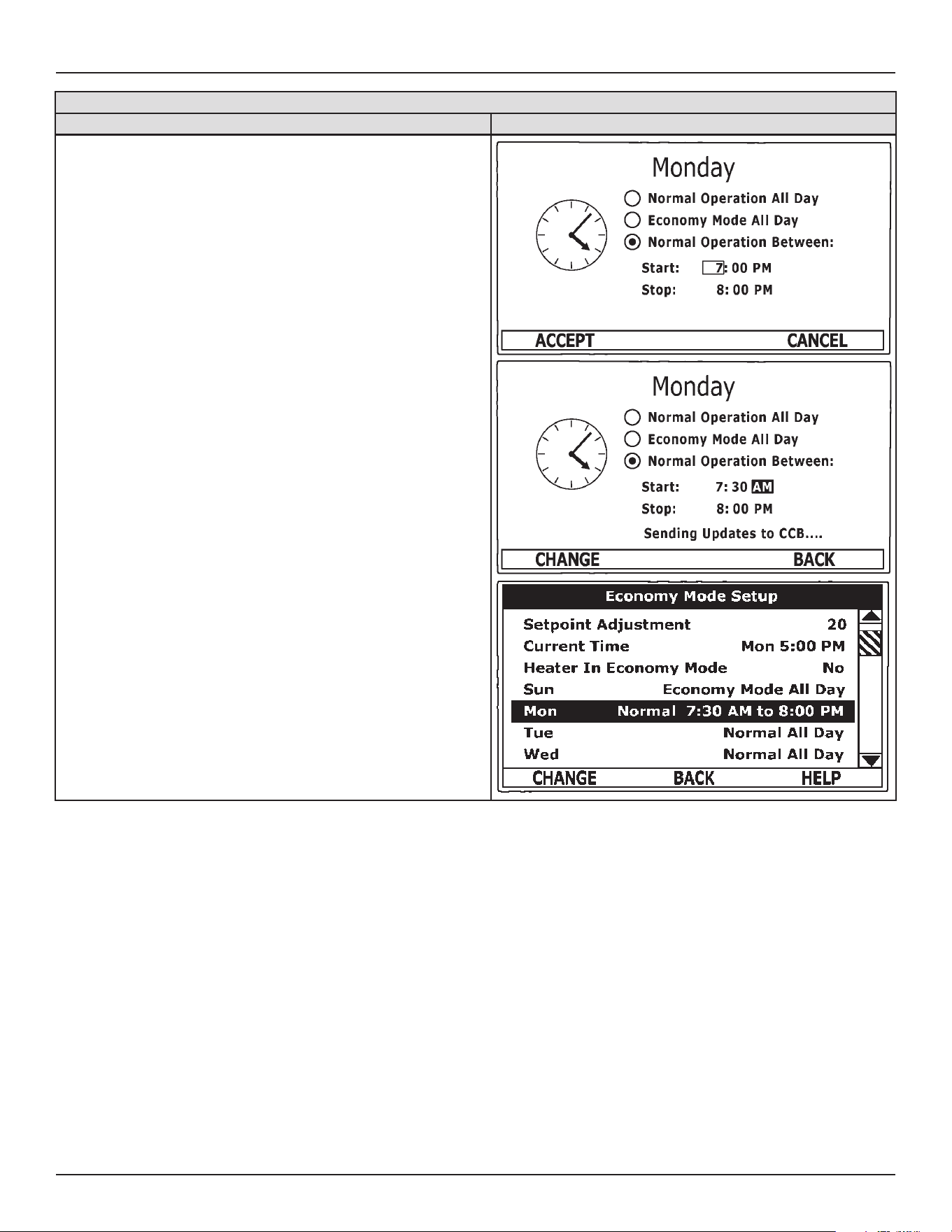
Control System Operation
Commercial Electric Water Heaters • 33
Daily Operating Mode Settings
ACTION DISPLAY
Normal Operation Between:
From the Economy Mode Setup menu Use the Up/Down and CHANGE but-
tons to enter the Mon sub menu as described above.
Use the Up/Down buttons to select (highlight in black) the “Normal Operation
Between” setting. Press the Operational Button underneath “SELECT” to
change the operating mode for Monday to Normal Operation Between. Note
that when this setting is selected Start and Stop time user settings appear on
the display.
Use the Up/Down buttons to navigate between the Start and Stop time Hour,
Minutes and AM/PM settings.
With each item selected press the Operational Button underneath
“CHANGE” to activate the adjustment mode for each setting. Use the Up/
Down buttons to change the value to the desired setting.
Press the Operational Button underneath “ACCEPT” to enter the new setting
or “CANCEL” to discard the new setting and retain the previous setting.
Press the Operational Button underneath “BACK” when nished to conrm
the new settings and update the control system. The display will return to the
Economy Mode Setup menu with the new settings shown for Mon.
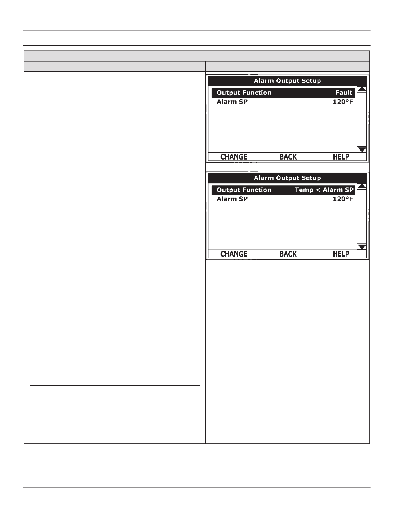
34 • Commercial Electric Water Heaters
Control System Operation
ALARM OUTPUT SETUP MENU
Alarm Output Setup Menu
ACTION DISPLAY
Permits user to set the condition (from a list of options) for when
the CCB’s integral alarm output relay will be energized. Alarm relay
connections (common, normally open, normally closed) are located
on the J3 terminal strip on the CCB. See Wiring Diagrams (page
43). Alarm output relay contacts are capable of switching 1 amp
maximum at 120 VAC.
The alarm relay operates in the background according to the settings
in this menu and is not capable of disabling water heater operation.
The alarm relay is used for external notication/verication of
various operational conditions such as fault conditions and heating
mode status. This relay can be used with building EMS (Energy
Management System) and other external supervisory controls.
Output Function - Adjustable user setting. Available options for the
Alarm Output Function setting are:
• Heating Mode: Used for heating mode on/o status
notication.
• Enable / Disable Closed: Used for notication and/or
verication of the enable/disable circuits open/closed status.
There are two enable/disable circuits available for external
supervisory control(s) at the J7 socket on the CCB. See Wiring
Diagrams (page 43). The Enable/disable circuit(s) status can
be viewed in the Heater Status Menu.
• Temp < Heater SP: Used for external notication when current
tank temperature drops below Operating Set Point.
• Temp < Alarm SP: Used for external notication when current
tank temperature drops below programmable Alarm SP.
• Fault or Alert: Used for external notication whenever a Fault
or Alert condition is active.
• Fault: Used for notication whenever a Fault condition is
active.
• Disabled: Disables the Alarm Relay Output Function.
Alarm SP - Adjustable user setting (90°F to 190°F) the control
system uses for the “Temp < Alarm SP” function described above.
This setting has no eect with any other Alarm Output functions.
Alarm Output Settings
Changing the user settings in this menu is done using the same
methods for changing the Operating Set Point.
Note: Adjustable user settings in the Alarm Output Setup menu are
unaected by Restore Factory Defaults.
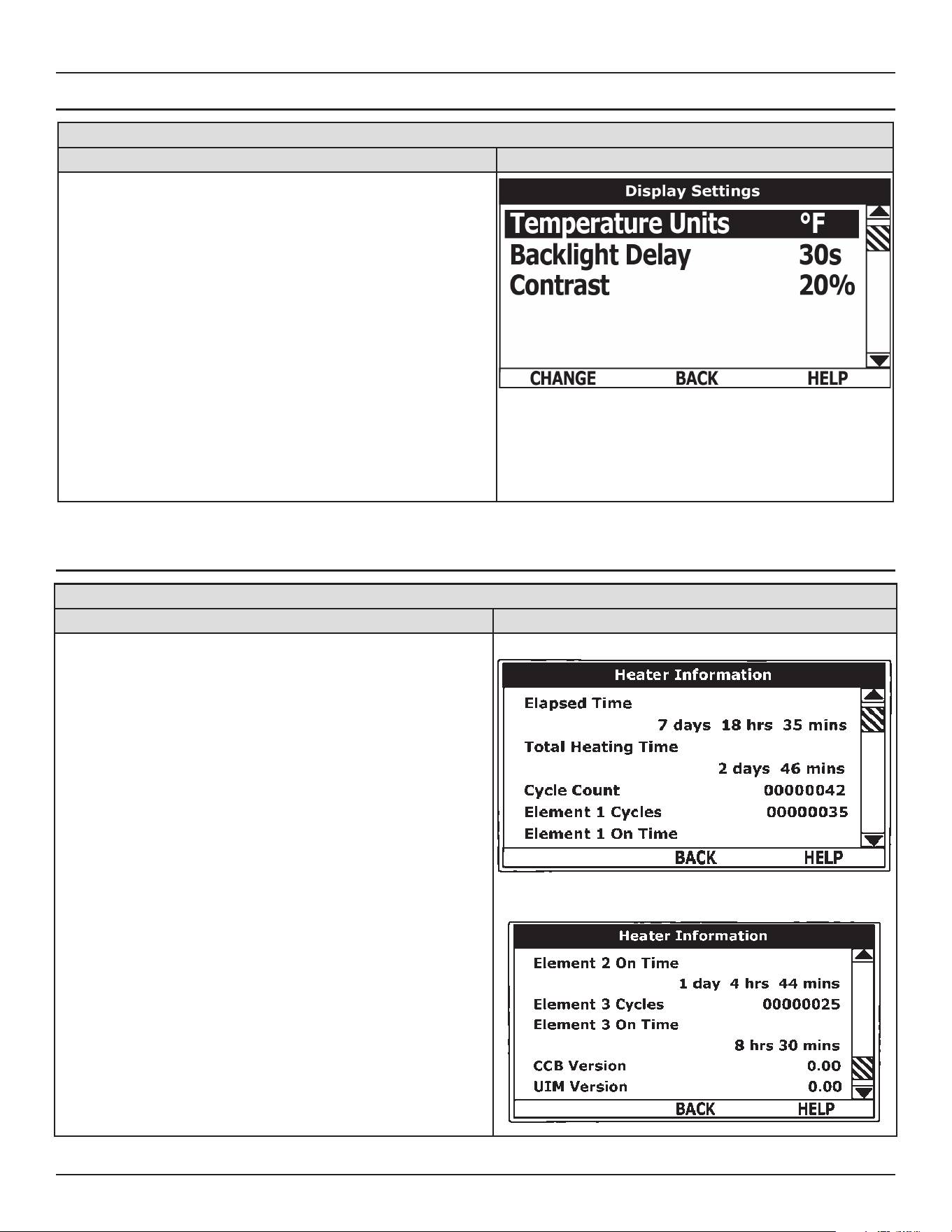
Control System Operation
Commercial Electric Water Heaters • 35
DISPLAY SETTINGS MENU
Display Settings Menu
ACTION DISPLAY
Permits user to set display options for viewing information on the
UIM’s LCD screen.
Temperature Units - Adjustable user setting that changes
temperature units display to Celsius °C or Fahrenheit °F.
Backlight Delay - Adjustable user setting that determines how long
the UIM’s LCD backlight remains illuminated after a key has been
pressed. Available settings are; Always O, 10, 30 or 60 seconds
and Always On.
Contrast - Adjustable user setting to adjust the UIM’s LCD screen
contrast between text and background.
Display Settings - Changing the user settings in this menu is done
using the same methods for changing the Operating Set Point.
Adjustable user settings in the Display Settings menu are unaected
by Restore Factory Defaults.
HEATER INFORMATION MENU
Heater Information Menu
ACTION DISPLAY
This menu displays non adjustable operational information.
Elapsed Time - Total accumulated time the control system (water
heater) has been energized.
Total Heating Time - Total accumulated time the control system
has been in the heating mode. IE: any heating elements have been
energized.
Element # Cycles - Total accumulated count of heating cycles for
each heating element.
Element # On Time - Total accumulated heating on time for each
heating element.
CCB Version - Software version for Central Control Board.
UIM Version - Software version for User Interface Module
Top of Menu
Bottom of Menu
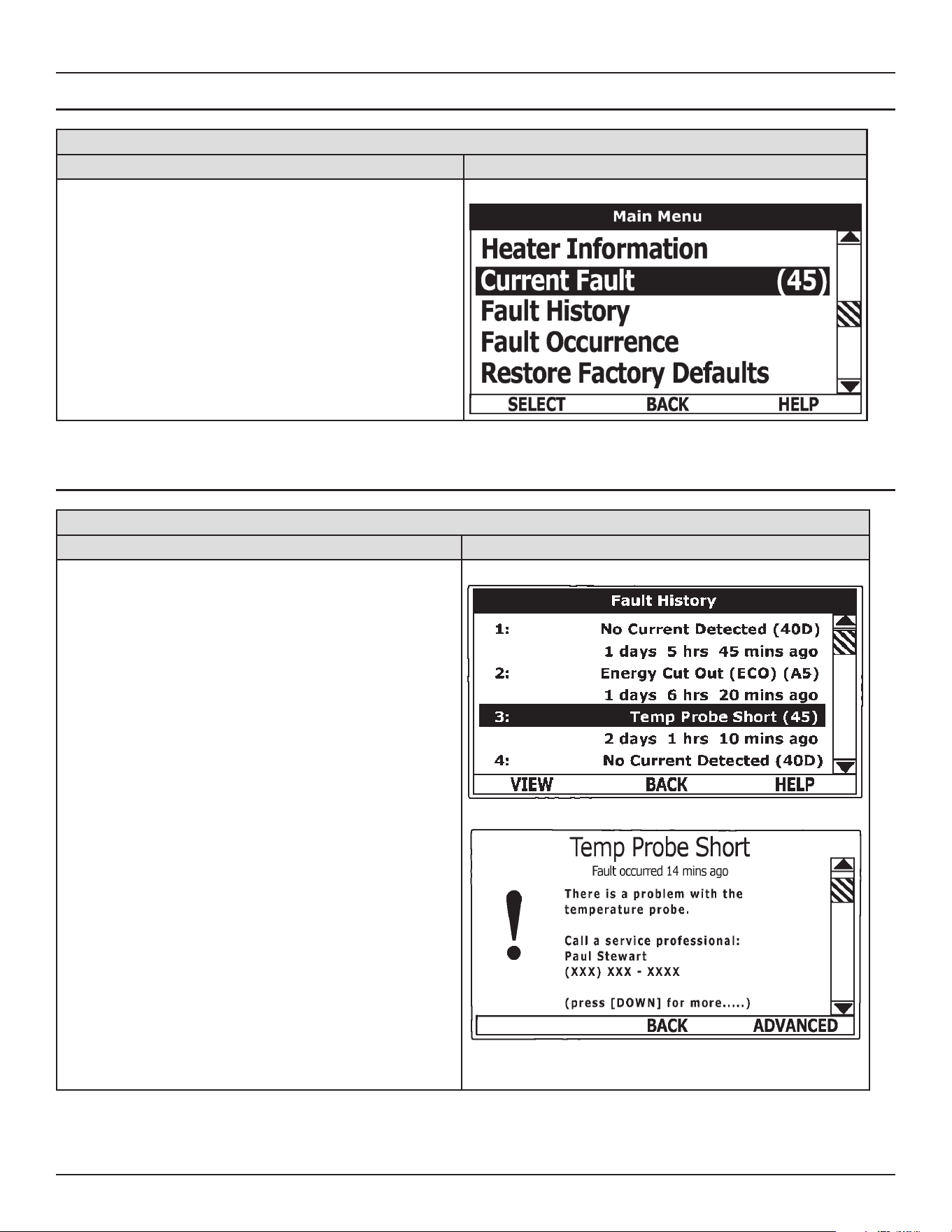
36 • Commercial Electric Water Heaters
Control System Operation
CURRENT FAULT / ALERT MENU
Table 9. Current Fault / Alert Menu
ACTION DISPLAY
This menu displays non adjustable operational information. With
the Fault History sub menu selected in Main Menu; press the
Operational Button underneath “SELECT” to display the current
Fault or Alert message. If there is not a Fault or Alert condition
currently active “(none)” is displayed to the right of this menu.
Main Menu - Current Fault Selected
FAULT HISTORY MENU
Fault History Menu/
ACTION DISPLAY
This menu displays non adjustable operational information.
The control system records and stores the last 9 Fault and
Alert messages in chronological order in this menu. The most
recent will be at the top of the list. A time stamp is displayed
below each listed Fault and Alert message showing when the
Fault or Alert condition occurred.
The Fault History is useful when dealing with intermittent
operational problems or when the customer has reset the
control system prior to a service agent’s arrival.
With a Fault or Alert item selected press the Operational Button
underneath “VIEW” to display the details for the Fault or Alert
message. The Fault/Alert message screen displays a brief
description of the condition, contact information and access
to the Advanced service information sub menu.
Fault History Menu
Current History/ Fault Message
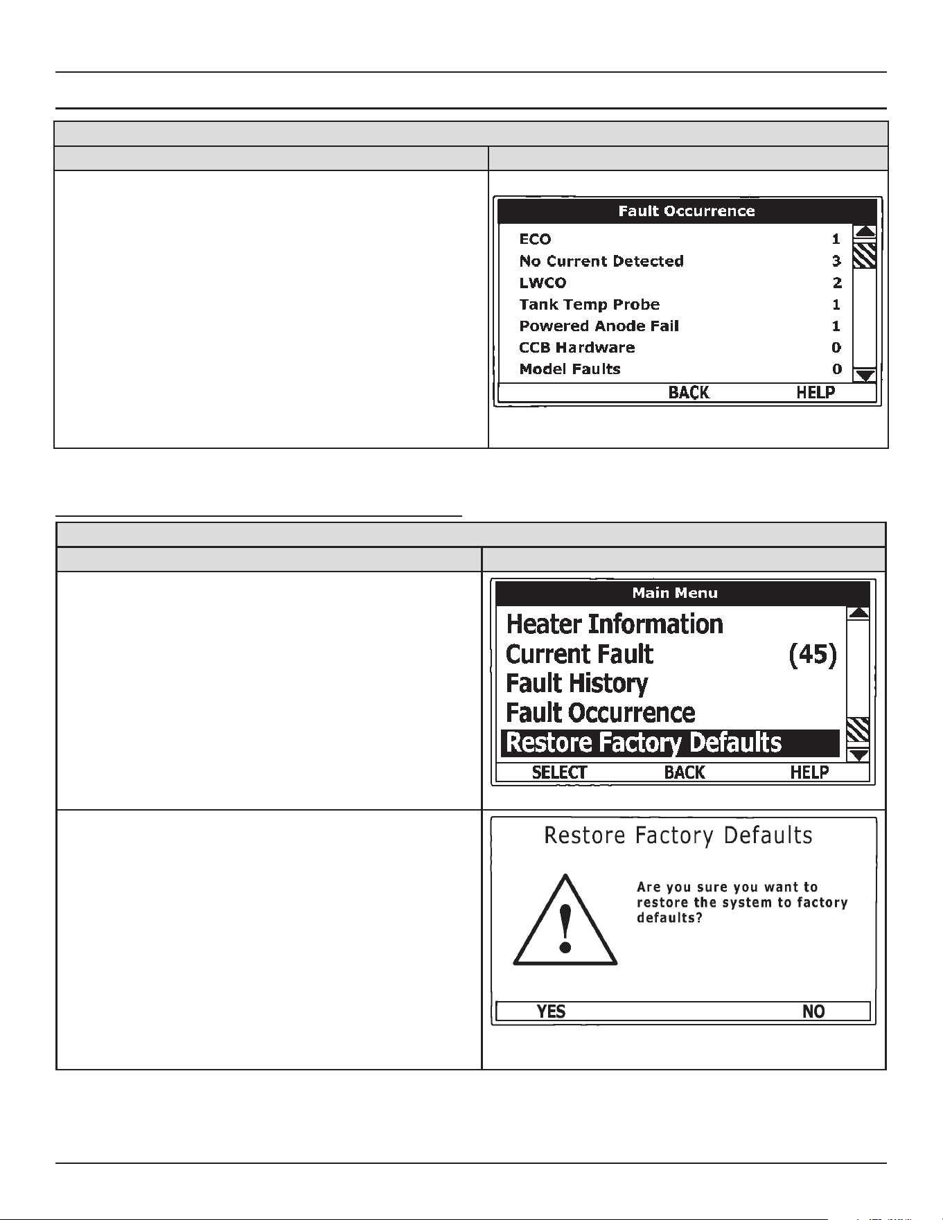
Control System Operation
Commercial Electric Water Heaters • 37
FAULT OCCURRENCE MENU
Fault Occurrence Menu
ACTION DISPLAY
Total accumulated number each individual Fault condition has
occurred is displayed in this menu. This running total of Fault
Occurrences can be useful in determining which (if any) operational
problems have been persistent.
Fault Occurrence Menu
RESTORE FACTORY DEFAULTS MENU
Restore Factory Defaults
ACTION DISPLAY
This control system menu allows the user to restore most of the
control system’s user settings to their factory default settings. User
settings in the Alarm Output Setup and Display Settings menus are
unaected by executing Restore Factory Defaults
From the Main Menu use the Up/Down buttons to select (highlight in
black) the “Restore Factory Defaults” menu.
Press the Operational Button underneath “SELECT.” The Restore
Factory Defaults menu will be displayed.
From the Restore Factory Defaults menu press the Operational Button
underneath “YES.” The display will show text conrming the factory
default settings have been restored.
Press the Operational Button underneath “BACK” to exit the Restore
Factory Defaults menu.
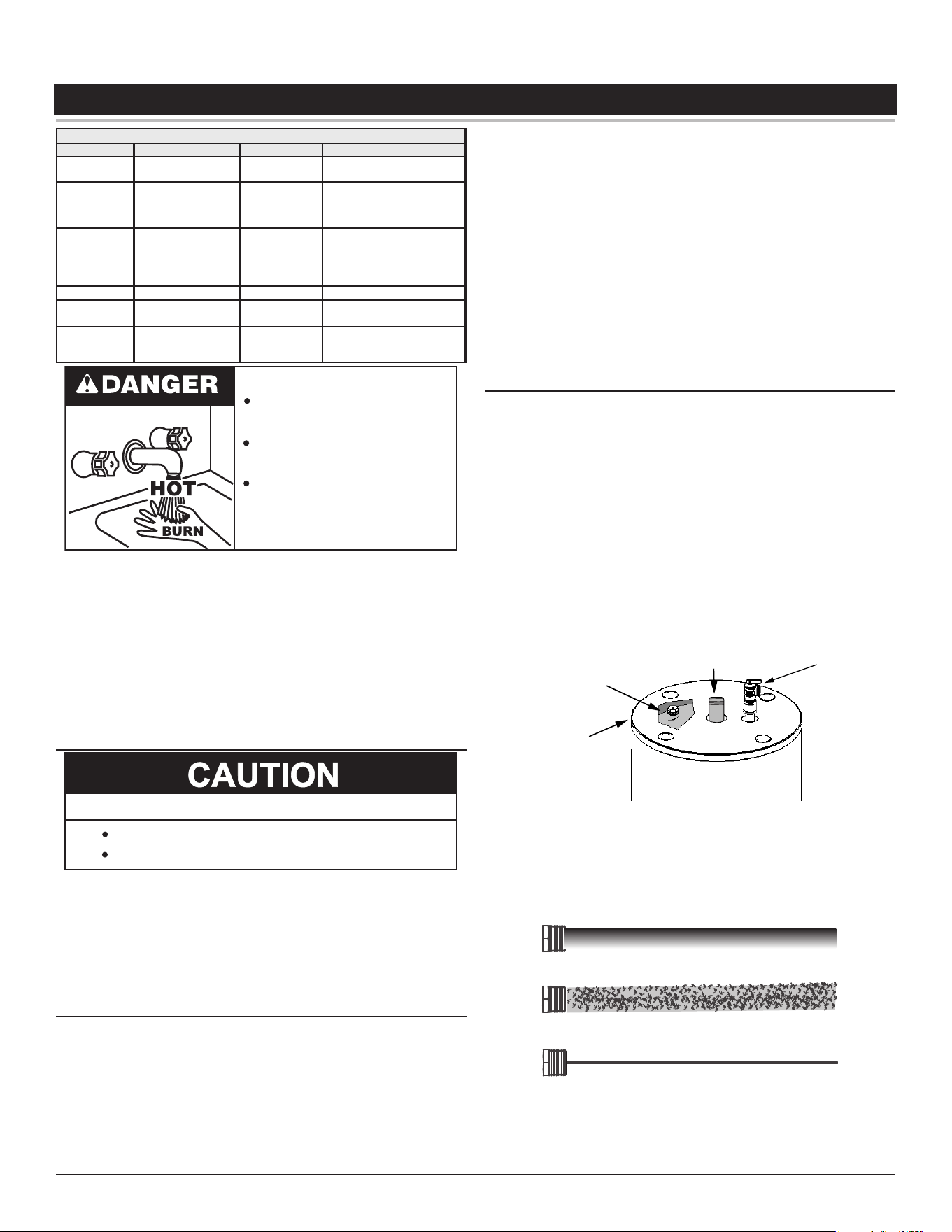
38 • Commercial Electric Water Heaters
MAINTENANCE
Table 10. Maintenance Schedule
Component Operation Interval Reference
Tank Drain and Flush
Every 6
Months
See Draining the Water
Heater.
Tank
Lime Scale Re-
moval
(Water Less Than
25 Grains Hard)
Not Required N/A
Tank
Lime Scale Re-
moval
(Water Greater
Than 25 Grains
Hard)
Annually See Lime Scale Removal.
Moving Parts Lubrication Not Required N/A
Powered
Anodes
Inspection/
Cleaning
Annually
See Anode Rod Mainte-
nance.
T&P Valve Test Operation Semi Annually
See Temperature-Pressure
Relief Valve Test (page
39).
Burn hazard.
Hot water discharge.
Keep clear of the Relief Valve
discharge outlet.
Water heater maintenance includes inspection and testing of the
Temperature Pressure Relief Valve, periodic tank ushing and
cleaning, and removal of lime scale from the heating elements.
Where used, water heating system circulating pumps should be oiled.
Tank flushing and element maintenance should be performed
in accordance with the maintenance schedule. See Table 10.
Tank sediment removal and element lime scale removal must be
performed when needed as determined by periodic inspections.
ANODE ROD MAINTENANCE
Avoid damage.
Property Damage Hazard
Inspection and replacement of anode rod required.
This water heater is equipped with a powered anode rod and a
consumable sacricial anode rod. The powered anode protects the
tank from corrosion by inducing electrical current between the anode
and the tank. The consumable anode works through electrolysis,
corroding itself to prevent corrosion of the tank. Both types require
annual inspection to ensure the maximum life of the water heater.
Inspecting/Replacing the Powered Anode
The powered anode is mounted on the inside of the cabinet near
the bottom of the water heater.
1. Turn o the electrical disconnect switch.
2. Shut o the water supply and open a nearby hot water faucet to
depressurize the water tank.
3. Drain the water heater tank to a point below the level of the anode.
See Draining And Flushing (page 39) for proper procedures.
4. Close drain valve.
5. Remove the wiring connection from the powered anode. Use a
socket wrench to unscrew and remove the old powered anode
rod.
6. Check for damage to the rod, its connections, and gaskets.
Replace the rod assembly if necessary.
7. Use pipe thread sealer tape or approved pipe sealant on threads
and install new powered anode rod.
8. Turn on water supply and open nearby hot water faucet to purge
air from water system. Check for any leaks and immediately
correct any if found.
9. Restart the water heater as directed in this manual.
Inspecting/Replacing the Sacricial Anode Rod
Replace the sacricial anode rod when its diameter is 3/8” (1 cm)
of an inch, or annually which ever is rst. Aggressive, very hot and
softened water causes rapid consumption of the anode rod requiring
frequent inspections. Call the toll free number on the back cover of
this manual for information on obtaining replacement anode rods.
The sacricial anode rod is mounted in the top of the water tank.
1. Turn o the electrical disconnect switch.
2. Shut o the water supply and open a nearby hot water faucet to
depressurize the water tank.
3. Drain approximately 5 gallons of water from tank. See Draining the
Water Heater (page 39) for proper procedures. Close drain valve.
4. Remove the top plug above the anode from the top cover.
Jacket Top
Cover
Anode
Water Outlet
T&P
Valve
Figure 8. Accessing the Anode
5. Use a socket wrench to unscrew an remove the anode rod and
inspect the rod.
Check the rod for damage or depletion.
New Rod
Partially Consumed Rod
Depleted Rod
If the rod is depleted, obtain a new rod and apply pipe thread
sealer tape or approved pipe sealant on threads to ensure there
is no leakage.
6. Install the new rod or reinstall the existing rod.
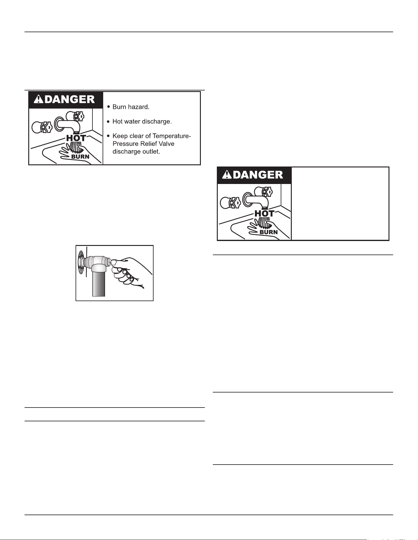
Maintenance
Commercial Electric Water Heaters • 39
7. Reinstall the top plug.
8. Rell the tank. See Filling The Water Heater (page 17).
9. Turn on the electrical power supply and restart the water heater See
Start Up and Operation (page 17).
TEMPERATURE-PRESSURE RELIEF VALVE TEST
The temperature-pressure relief valve must be manually operated
at least once a month. Lift the lever at the top of valve several times
until the valve seats properly and operates freely. See Figure 9.
When checking the temperature-pressure relief valve operation,
make sure that (1) no one is in front of or around the outlet of the
temperature-pressure relief valve discharge line, and (2) that the
water discharge will not cause any property damage, as the water
may be extremely hot. Use care when operating valve as the valve
may be hot.
Figure 9. Testing the T&P Relief Valve
If after manually operating the valve, it fails to completely reset and
continues to release water, immediately close the cold water inlet
to the water heater, follow the draining instructions in the Start Up
section of this manual, and replace the temperature-pressure relief
valve with a properly rated/sized new one.
If the temperature-pressure relief valve on the water heater weeps
or discharges periodically, this may be due to thermal expansion.
Consult your local water supplier or a Qualied Service Agency for
further information. Do not plug the temperature-pressure relief valve.
DRAINING AND FLUSHING
Draining the Water Heater
It is recommended that the water heater storage tank be drained and
ushed every 6 months to reduce sediment buildup. The water heater
should be drained if being shut down during freezing temperatures.
Maintenance and service procedures may also require draining the
heater See Features and Components (page 8) for the location of
the water heater components described below.
1. Turn o the electrical supply to the water heater at the breaker or
disconnect switch.
2. Ensure the cold water inlet valve is open.
3. Open a nearby hot water faucet and let the water run until the
water is no longer hot.
4. Close the cold water inlet valve to the water heater.
5. Connect a hose to the water heater drain valve and terminate it to an
adequate drain.
6. Open the water heater drain valve and allow all the water to drain
from the storage tank.
7. Close the water heater drain valve when all water in the storage tank
has drained.
8. Close the hot water faucet opened in Step 3.
9. If the water heater is going to be shut down for an extended period,
the drain valve should be left open.
Follow FILLING instructions when restoring hot water service. See
Filling The Water Heater (page 17).
• Burn hazard.
• Hot water discharge.
• Keep hands clear of drain
valve discharge.
Flushing the Water Heater
The water heater drain valve should be opened periodically to help
prevent sediment buildup on the tank bottom.
1. Turn o the electrical disconnect switch.
2. Open a nearby hot water faucet until the water is no longer hot, then
close the hot water faucet.
3. Attach hose to outlet opening of drain valve and direct end to drain.
• Open the drain valve by turning the hand wheel to the left
(counterclockwise). Allow water to ow until it runs clean.
• If water does not ow from opened drain valve, follow
instructions for sediment removal.
4. When nished ushing:
• Close heater drain valve and remove hose.
• Turn on electricity.
SEDIMENT REMOVAL
Water borne impurities consist of ne particles of soil and sand which
settle out and form a layer of sediment on the bottom of the tank. In
time, if not removed, the level of sediment might reach the heating
elements and cause their failure.
For convenience, sediment removal and element lime scale removal
should be performed at the same time as follows.
LIME SCALE REMOVAL
Lime scale accumulations on the heating elements is a normal
condition, common to all immersion type elements. Factors which
aect the amounts of this formation are:
1. Amount of hot water used. As the volume of the water heated
increases, more scale results.

40 • Commercial Electric Water Heaters
Maintenance
2. Water temperature. As the temperature of the water is increased,
more scale is deposited on the elements.
3. Characteristics of water supply.
4. Regardless of water treatment, the elements should be examined
regularly.
Lime scale accumulations may cause noises to occur during
operation.
It is recommended that a heating element be removed periodically
for examination. If it is scaled, all of the elements should be removed
and cleaned. If the tank bottom has an accumulation of sediment it
should be cleaned.
Lime scale should be removed by dissolving the accumulation in
UN-LIME
®
delimer. Do not use muriatic or hydrochloric acid base
deliming solutions to remove lime scale from the elements.
The Process For Lime Scale Removal Is As Follows:
1. Turn o electrical disconnect switch.
2. Drain the heater following DRAINING instructions.
3. Open front panel.
4. Disconnect the element wiring. Try not to disturb the wiring
unnecessarily and reconnection will be easier.
5. Unscrew each element.
6. Remove the elements and gaskets from the openings.
• Use a twisting, pulling action to remove elements scaled
beyond the size of the tank openings.
• Brush loose scale from elements.
7. Lime scale removal:
• Place limed ends of heating elements into UN-LIME
delimer and allow scale to dissolve. Do not permit delimer
or water to contact heating element electrical terminals.
• Silicates, sulfates, and aluminates must be removed
by scraping or other mechanical means. Lime scale
dissolvents will not remove these types of scale which are
occasionally encountered.
Call the manufacturer to purchase UN-LIME and heating element
gaskets.
Other Scale Removal:
1. Flush cleaned ends of elements with water when deliming or
cleaning is completed.
2. Remove sediment and scale from the tank bottom through the
access provided by the element openings or drain valve opening.
The cold water inlet valve and drain valve may be opened to
aid the cleanout process.
3. Clean remaining gasket material from tank and element anges.
Don not reuse original element gaskets.
4. Put new gaskets on each element and install into tank openings.
5. Attach element wires to connection points from which they were
removed.
6. Follow FILLING instructions to restore hot water service.
• Check for water leaks around elements and proper
operation when heater is lled.
• Close the panel.
Commercial Electric Water Heaters • 41
TROUBLESHOOTING
Before calling for service, check the following points to see if the
cause of trouble can be identied and corrected. Reviewing this
checklist may eliminate the need of a service call and quickly restore
hot water service.
The illustration in the Features and Components (page 8) identies
the location of most of the heater components.
● Before removing any access panels or
servicing the water heater, make sure
the the electrical supply to the water
heater is turned OFF.
Electrical Shock Hazard
● Failure to follow these instructions can
result in personal injury or death.
BE SURE TO TURN OFF THE ELECTRICITY (ELECTRICAL
DISCONNECT SWITCH) WHEN CHECKING EQUIPMENT.
NOT ENOUGH OR NO HOT WATER
1. Be certain the electrical disconnect switch serving the water
heater is in the ON position. The pilot toggle switch on the cabinet
should be ON.
In some areas water heater electrical service may be limited
by the power company. If the heater operates on a controlled
circuit, heater recovery may be aected.
The optional manual override switches on the cabinet front may
be turned o, de-energizing the elements.
2. Check the fuses.
The electrical disconnect switch usually contains fuses.
The water heater has fuses located behind the cabinet front
door. See Features and Components (page 8) for their location.
3. If the water was excessively hot, and is now cold, the ECO high
limit switch may have activated.
See Temperature Regulation (page 18) for more information on
how to reset the ECO high limit controls.
Repeated activation of the ECO high limit switch should be
investigated by a qualied service technician or qualied agency.
4. The storage capacity and/or recovery rate of the water heater
may have been exceeded by a large demand for hot water. See
Table 1 (page 10) in this manual.
Large demands require a recovery period to restore water
temperature.
5. Cold incoming water temperature will lengthen the time required
to heat water to the desired temperature.
6. If the heater was installed when incoming water temperature was
warm, colder water creates the eect of less hot water.
7. Sediment or lime scale may be aecting water heater operation.
See Maintenance (page 38) for details.
WATER IS TOO HOT
See Temperature Regulation (page 18).
WATER HEATER MAKES STRANGE SOUNDS
8. Sediment or lime scale accumulations on the elements causes
sizzling and hissing noises when the heater is operating.
The sounds are normal, however, the tank bottom and elements
should be cleaned. See Maintenance (page 38) for details.
9. Some of the electrical components of the water heater make
sounds which are normal, for example, contactors will click or
snap as the heater starts and stops.
IF YOU CANNOT IDENTIFY OR CORRECT THE SOURCE
OF MALFUNCTION:
10. Place the water heater electrical disconnect switch in the OFF
position.
11. Close the cold water inlet valve to the heater.
12. Call the toll free number on the back cover of this manual for
further assistance.
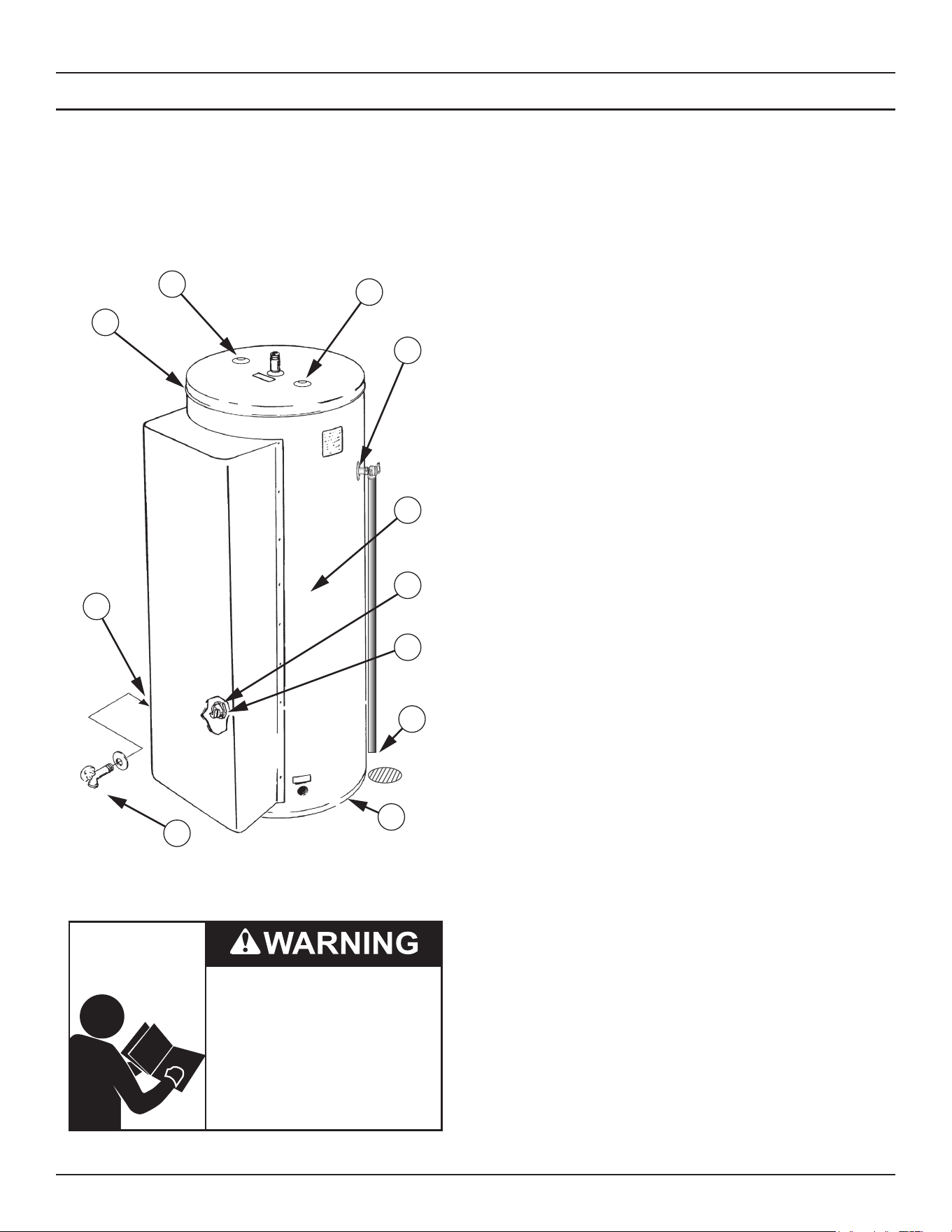
42 • Commercial Electric Water Heaters
Troubleshooting
CHECKING FOR LEAKS
Use this illustration as a guide when checking for sources of water leakage. You or your dealer may be able to correct what appears to
be a problem.
Water leaks which appear at the water heater bottom or on the surrounding oor may be caused by condensation, loose connections or
relief valve operation and leakage. Do not replace the water heater until full inspection of all potential leak points is made and corrective
steps taken to stop the leak.
Leakage from other appliances, water lines, or ground should also be suspected until proven otherwise.
1
2
3
5
6
7
9
10
8
4
2
Figure 10. Leakage Checkpoints
Read and understand this instruction
manual and the safety messages
herein before installing, operating or
servicing this water heater.
Failure to follow these instructions and
safety messages could result in death
or serious injury.
This manual must remain with the
water heater.
Never use this water heater unless it is completely lled with water.
To prevent damage to the tank, the tank must be lled with water.
Water must ow from the hot water faucet before turning the water
heater.
1. Where possible remove or lift top cover to examine threads of
ttings installed into tank for evidence of leakage. Correct tting
leaks as necessary.
2. *The anode rod tting may be leaking.
3. *The temperature-pressure relief valve may be leaking at the
tank tting.
4. Water on the side of the tank may be condensation due to the
panel or insulation not being in place.
5. Defective element which leaks at terminals or thru ange. Replace
element*
6. Loose element/gasket leak
1) Screw-in type: tighten with 1-1/2” socket wrench. If leak
continues, remove element*, discard gasket and clean thread
areas. Apply non-hardening Permatex Number 2 to thread
areas, install new gasket and screw element into tting until
it seats. Tighten 1/2 to 3/4 turn with wrench.
2) Flange type: tighten screw with wrench. If leak continues
remove element* and discard gasket. Clean gasket seating
areas and re-install element with new gasket. A new element
may be required where threads have become rusted or
damaged, preventing tightening.
7. Small amounts of water from temperature-pressure relief valve
may be due to thermal expansion, high water pressure in your
area, or a defective temperature-pressure relief valve.
8. All water which appears at the heater bottom or on the surrounding
oor may be caused by condensation, loose connections or relief
valve operation and leakage. Do not replace the heater until a
full inspection of all potential leak points is made and corrective
steps taken to stop the leak.
9. Water from a drain valve may be due to the valve being slightly
opened.
10. *The drain valve may be leaking at the tank tting.
Leakage from other water heaters, water lines, or ground seepage
should also be checked.
* To check where threaded portion enters tank, insert cotton
swab between jacket opening and tting. If cotton is wet,
follow instructions in Draining the Water Heater (page 39)
and then remove tting. Put pipe dope or teon tape on the
threads and replace. Then follow the instructions in Installing
the Water Heater (page 12) and Start Up and Operation (page
17) .
* Contact your dealer as it is necessary to shut o electricity
and drain tank to perform procedure.
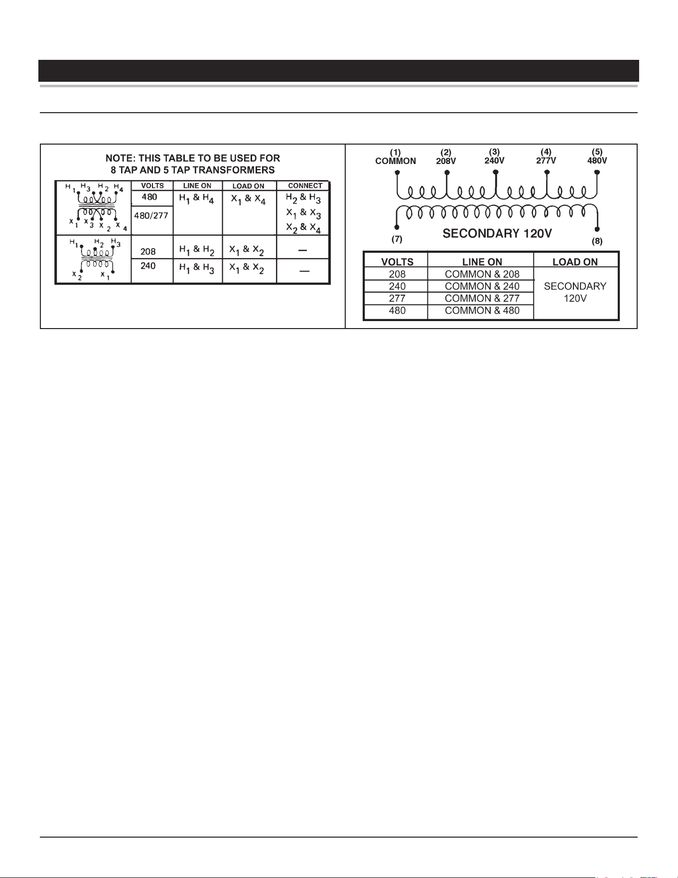
Commercial Electric Water Heaters • 43
DIAGRAMS
WIRING DIAGRAMS
Figure 11. 120 VAC Control Circuit Transformer Connections - Electronic Control Models
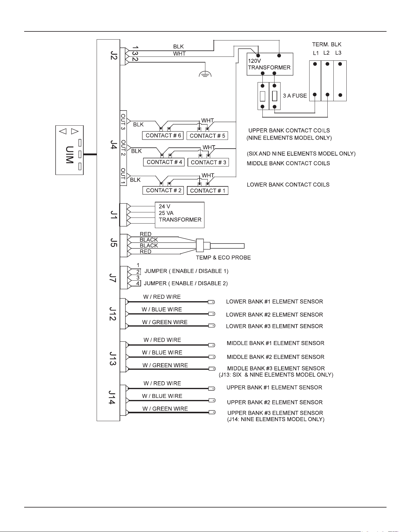
44 • Commercial Electric Water Heaters
Diagrams
Figure 12. Central Control Board (CCB) Control Circuit Diagram - Electronic Control Models
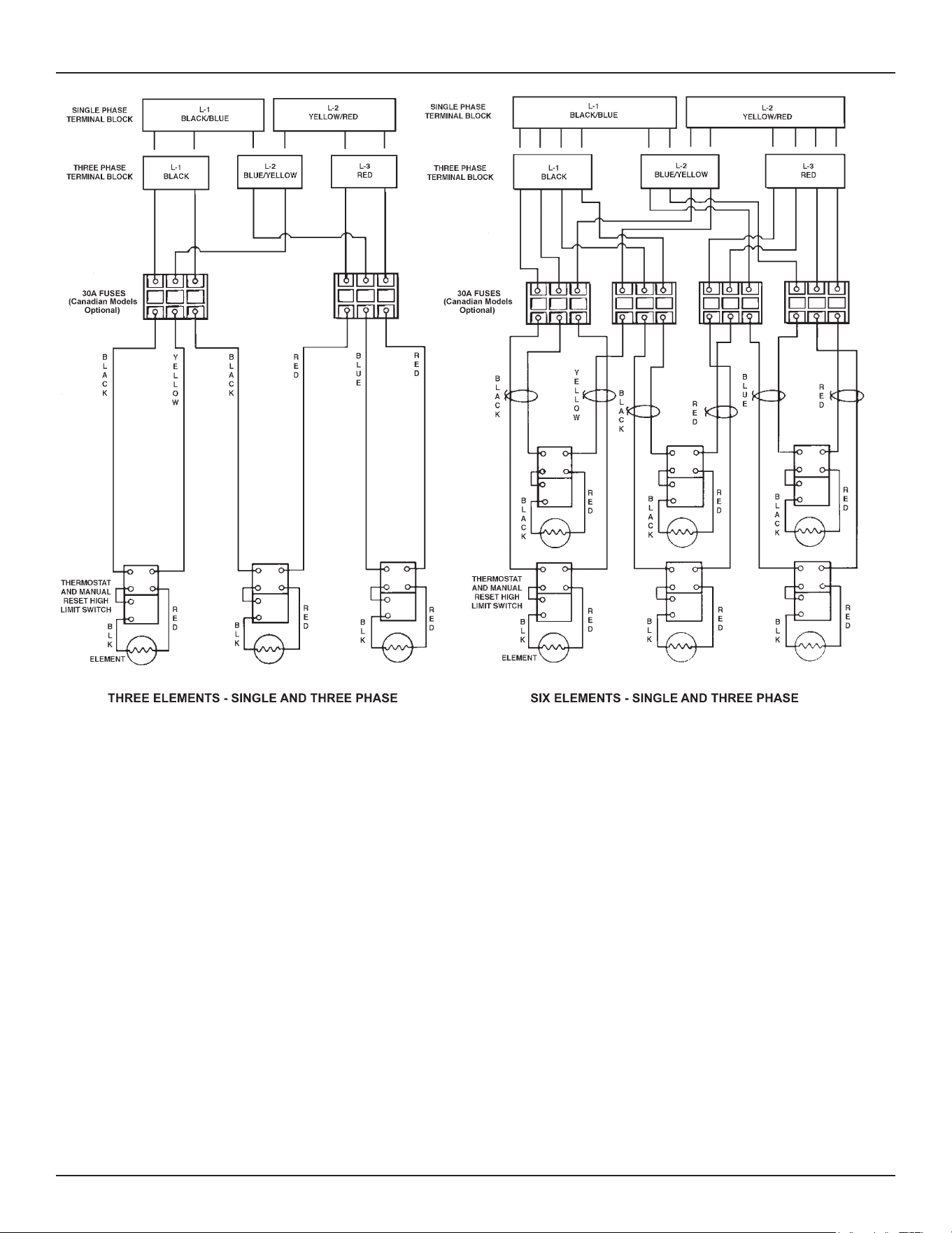
Diagrams
Commercial Electric Water Heaters • 45
Figure 13. Power Circuit Diagrams - Surface Mount Control Models
The water heater’s electrical components are pictured and identied on page 8. The following describes the heater circuits and includes
wiring diagrams. All heater circuits are designed for 60/50 hertz alternating current. The water heater circuit wiring is 12 AWG, AWM, or TEW
type, rated 600 volts, 105°C. Fusing consists of two 30 amp fuses for each element. Fusing is an optional feature for Canadian models.
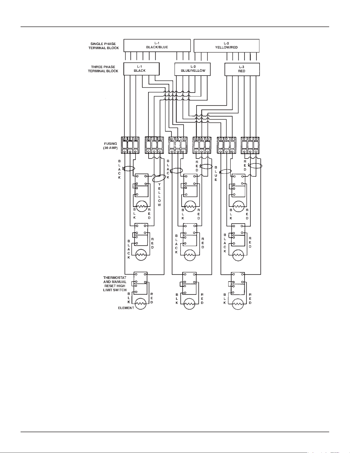
46 • Commercial Electric Water Heaters
Diagrams
Figure 14. Nine Elements - Single and Three Phase
Conversion to Single Phase
When the heater is shipped for connection to a three-phase electrical
service, it may be connected to a single-phase electrical service of
the same voltage by:
1. Disconnect blue wires from terminal L2.
2. Connect all blue wires to terminal L1 (with black wires).
3. Disconnect all red wires from terminal L3.
4. Connect all red wires to terminal L2 (with yellow wires).
5. Connect incoming power to terminals L1 and L2.
Conversion to Three Phase
When heater is shipped for connection to a single-phase electrical
service, it may be connected to a three-phase electrical service of
the same voltage by:
1. Disconnect blue wires from terminal L1
2. Disconnect red wires from terminal L2.
3. Connect all blue wires to terminal L2 (with yellow wires).
4. Connect red wires to terminal L3.
5. Connect incoming power to terminals L1, L2 and L3.
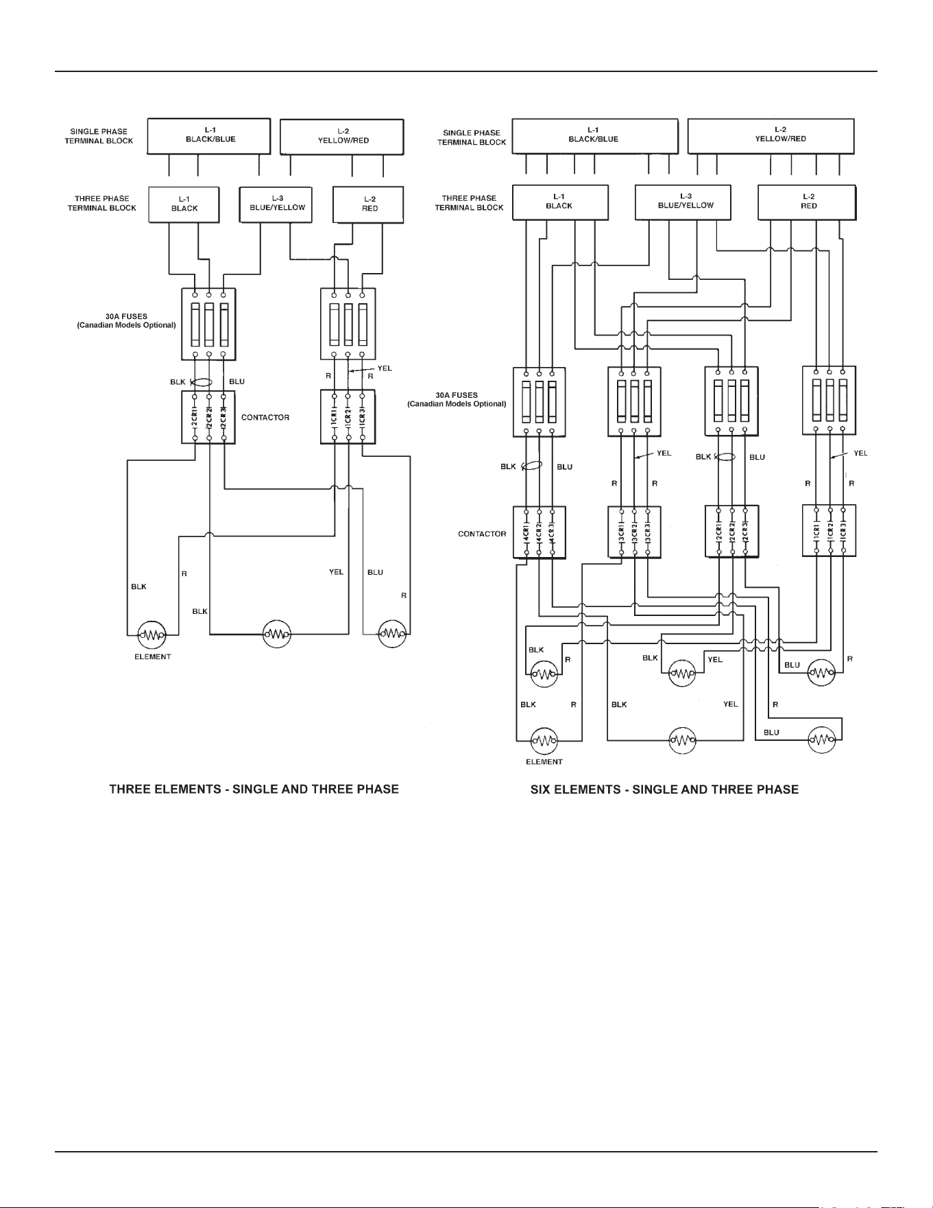
Diagrams
Commercial Electric Water Heaters • 47
Figure 15. Power Circuit Diagrams - Electronic Control Models
The water heater’s electrical components are pictured and identied on page 7. The following describes the heater circuits and includes
wiring diagrams. All heater circuits are designed for 60/50 hertz alternating current. The water heater circuit wiring is 12 AWG, AWM, or TEW
type, rated 600 volts, 105°C. Fusing consists of three 30 amp fuses for each contactor. Fusing is an optional feature for Canadian models.
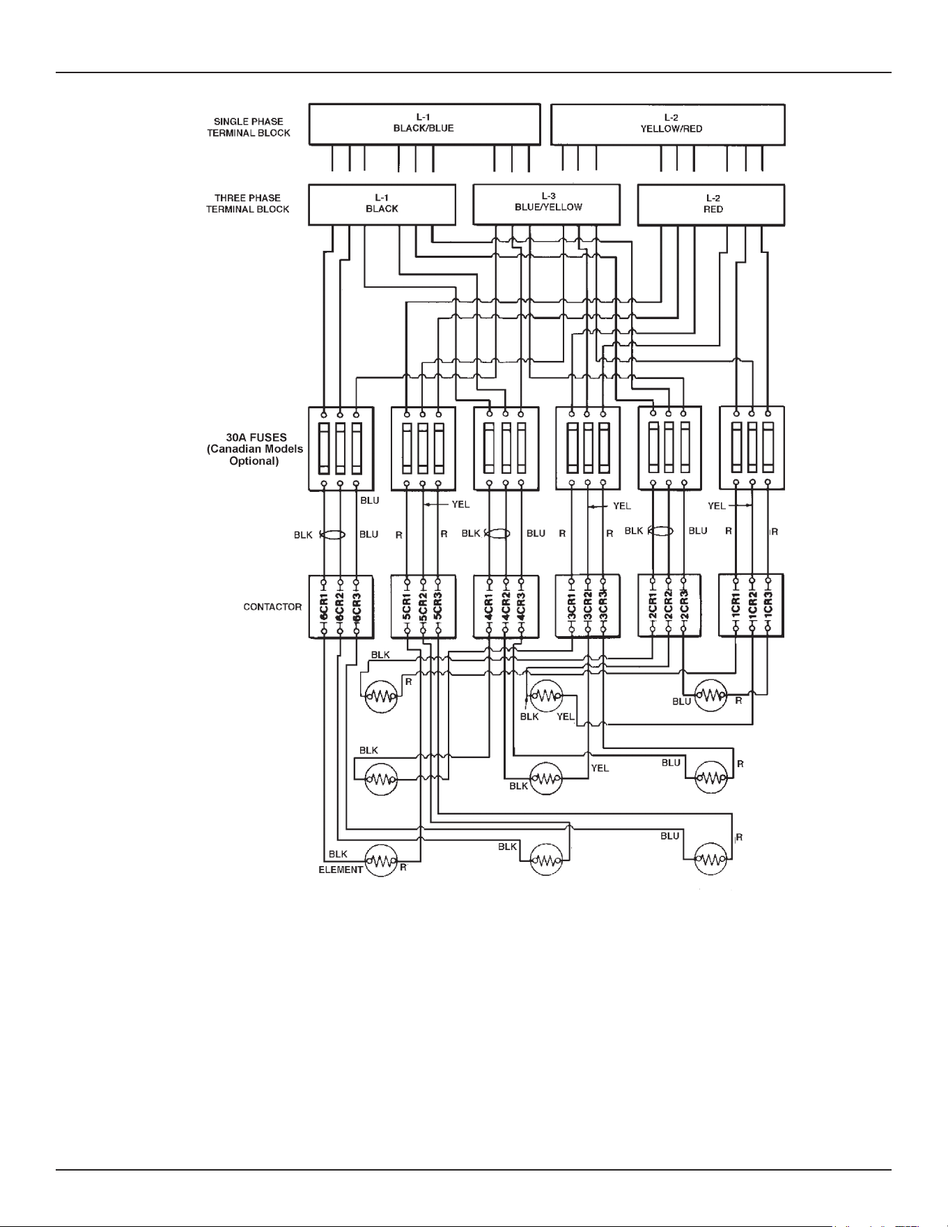
48 • Commercial Electric Water Heaters
Diagrams
Figure 16. Nine Element - Single And Three Phase
Conversion to Single Phase
When the heater is shipped for connection to a three-phase electrical
service, it may be connected to a single-phase electrical service of
the same voltage by:
1. Disconnect blue wires and yellow wires from terminal L3.
2. Reconnect all blue wires to terminal L1 (with black wires).
3. Reconnect all yellow wires to terminal L2 (with red wires).
4. Connect incoming power to terminals L1 and L2.
Conversion to Three Phase
When heater is shipped for connection to a single-phase electrical
service, it may be connected to a three-phase electrical service of
the same voltage by:
1. Disconnect blue wires from terminal L1.
2. Disconnect yellow wires from terminal L2.
3. Reconnect all blue wires and yellow wires to terminal L3.
4. Connect incoming power to terminals L1, L2, and L3.
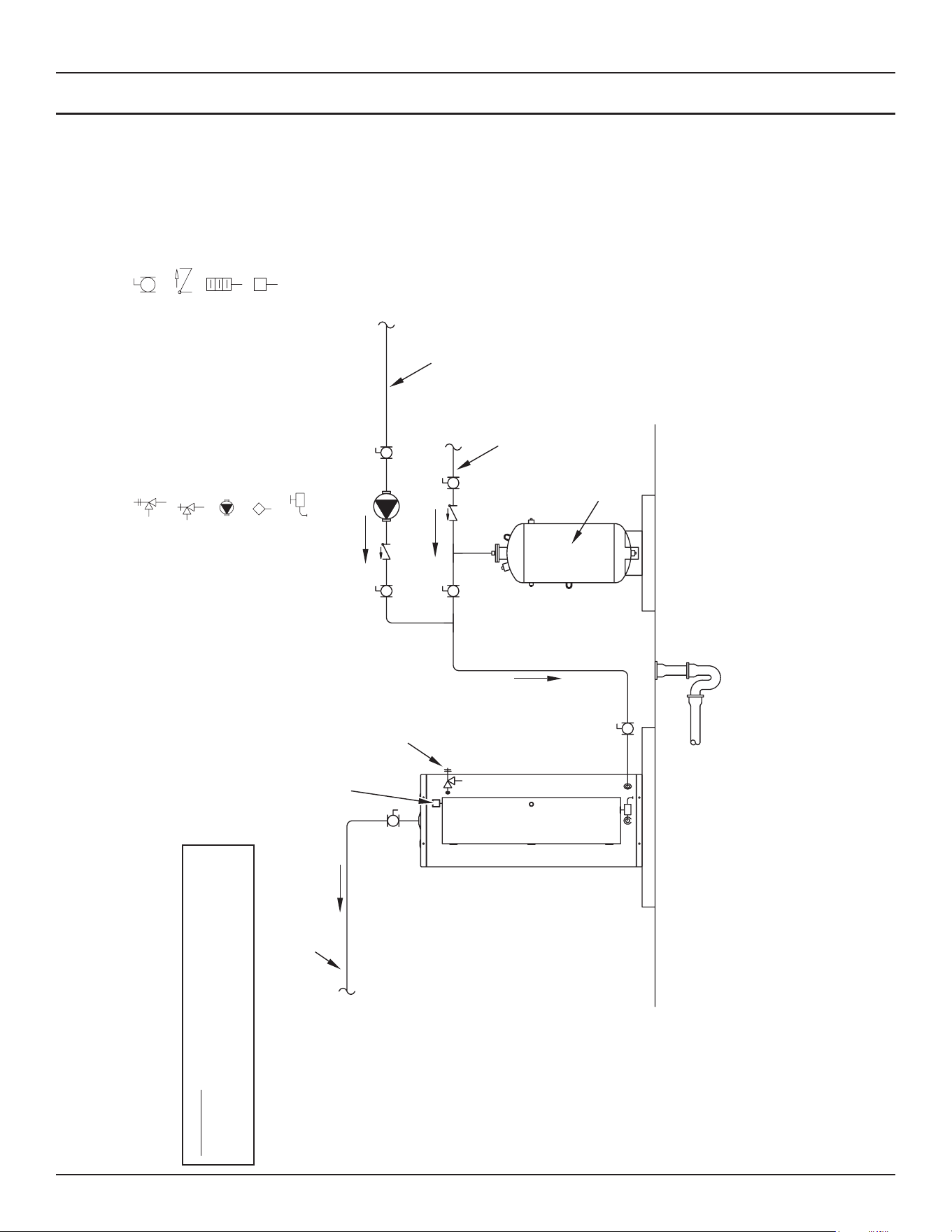
Diagrams
Commercial Electric Water Heaters • 49
PIPING DIAGRAMS
NOTES:
1. Preferred piping diagram.
2. The temperature and pressure relief valve setting shall not exceed pressure rating of any component in the system.
3. Service valves are shown for servicing unit. However, local codes shall govern their usage.
COMMERCIAL ELECTRIC - (1 UNIT)
LEGEND
TEMPERATURE & PRESSURE
RELIEF VALVE
PRESSURE RELIEF VALVE
CIRCULATING PUMP
TANK TEMPERATURE CONTROL
DRAIN
FULL PORT BALL VALVE
TEMPERATURE GAGE
WATER FLOW SWITCH
CHECK VALVE
WARNING: THIS DRAWING SHOWS SUGGESTED
PIPING CONFIGURATION AND OTHER DEVICES;
CHECK WITH LOCAL CODES AND ORDINANCES
FOR ADDITIONAL REQUIREMENTS.
FINISHED
FLOOR
HOT WATER
TO FIXTURES
FUSED
DISCONNECT
SWITCH
HOT WATER
RETURN
EXPANSION
TANK
COLD WATER
SUPPLY
PIPE T&P TO
OPEN DRAIN
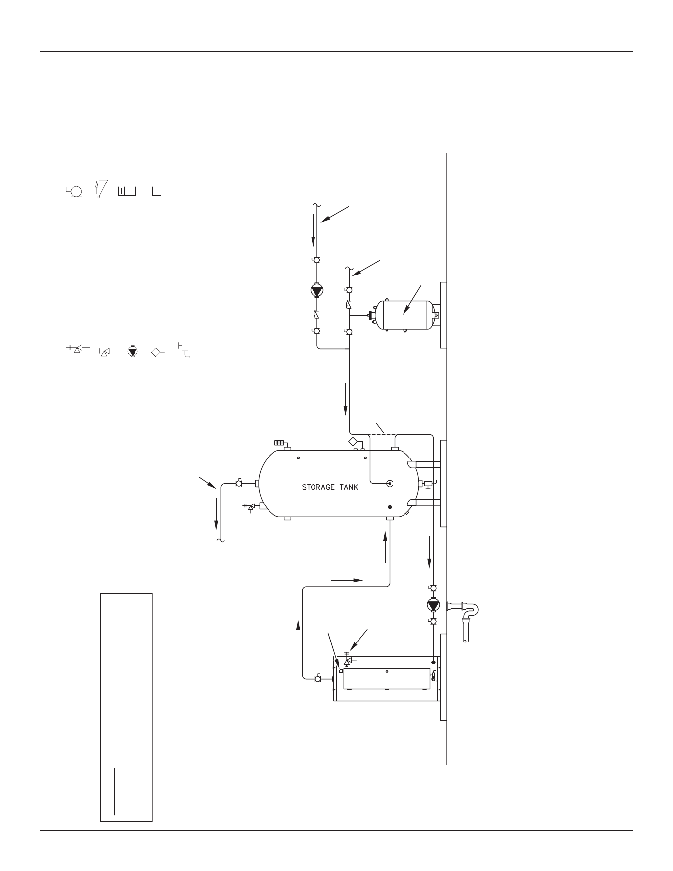
50 • Commercial Electric Water Heaters
Diagrams
NOTES:
1. Preferred piping diagram.
2. The temperature and pressure relief valve setting shall not exceed pressure rating of any component in the system.
3. Service valves are shown for servicing unit. However, local codes shall govern their usage.
4. The Tank Temperature Control should be wired to and control the pump between the water heater(s) and the storage tank(s).
5. The water heater’s operating thermostat should be set 5 degrees F higher than the Tank Temperature Control.
COMMERCIAL ELECTRIC - (1 UNIT) WITH VERTICAL STORAGE TANK
LEGEND
TEMPERATURE & PRESSURE
RELIEF VALVE
PRESSURE RELIEF VALVE
CIRCULATING PUMP
TANK TEMPERATURE CONTROL
DRAIN
FULL PORT BALL VALVE
TEMPERATURE GAGE
WATER FLOW SWITCH
CHECK VALVE
WARNING: THIS DRAWING SHOWS SUGGESTED
PIPING CONFIGURATION AND OTHER DEVICES;
CHECK WITH LOCAL CODES AND ORDINANCES
FOR ADDITIONAL REQUIREMENTS.
FINISHED
FLOOR
HOT WATER
TO FIXTURES
FUSED
DISCONNECT
SWITCH
EXPANSION
TANK
ALT. COLD WATER
CONNECTION
HOT WATER
RETURN
COLD WATER
SUPPLY
PIPE T&P TO
OPEN DRAIN
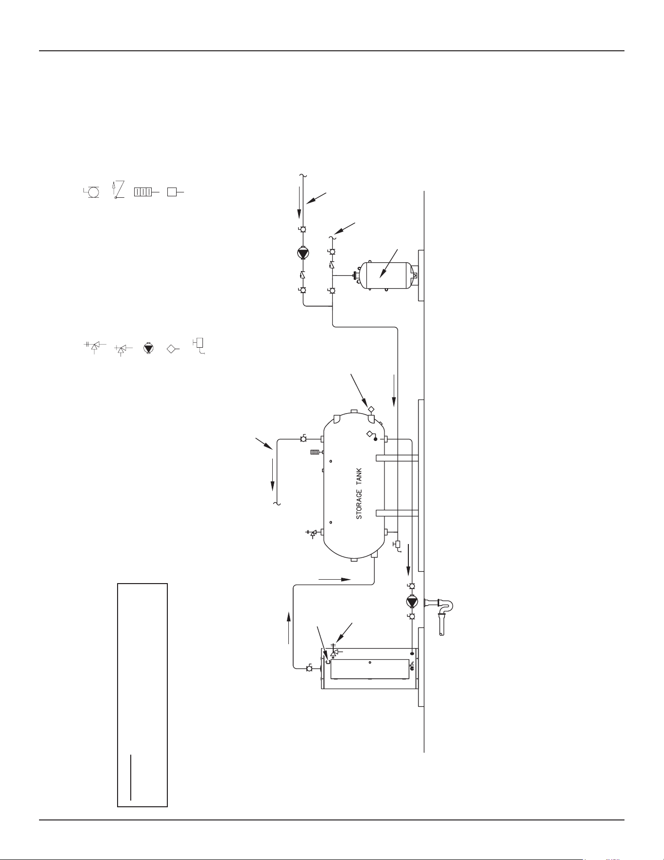
Diagrams
Commercial Electric Water Heaters • 51
NOTES:
1. Preferred piping diagram.
2. The temperature and pressure relief valve setting shall not exceed pressure rating of any component in the system.
3. Service valves are shown for servicing unit. However, local codes shall govern their usage.
4. The Tank Temperature Control should be wired to and control the pump between the water heater(s) and the storage tank(s).
5. The water heater’s operating thermostat should be set 5 degrees F higher than the Tank Temperature Control.
COMMERCIAL ELECTRIC - (1 UNIT) WITH HORIZONTAL STORAGE TANK
LEGEND
TEMPERATURE & PRESSURE
RELIEF VALVE
PRESSURE RELIEF VALVE
CIRCULATING PUMP
TANK TEMPERATURE CONTROL
DRAIN
FULL PORT BALL VALVE
TEMPERATURE GAGE
WATER FLOW SWITCH
CHECK VALVE
WARNING: THIS DRAWING SHOWS SUGGESTED
PIPING CONFIGURATION AND OTHER DEVICES;
CHECK WITH LOCAL CODES AND ORDINANCES
FOR ADDITIONAL REQUIREMENTS.
FINISHED
FLOOR
HOT WATER
TO FIXTURES
EXPANSION
TANK
ALTERNATE
LOCATION
HOT WATER
RETURN
COLD WATER
SUPPLY
FUSED
DISCONNECT
SWITCH
PIPE T&P TO
OPEN DRAIN
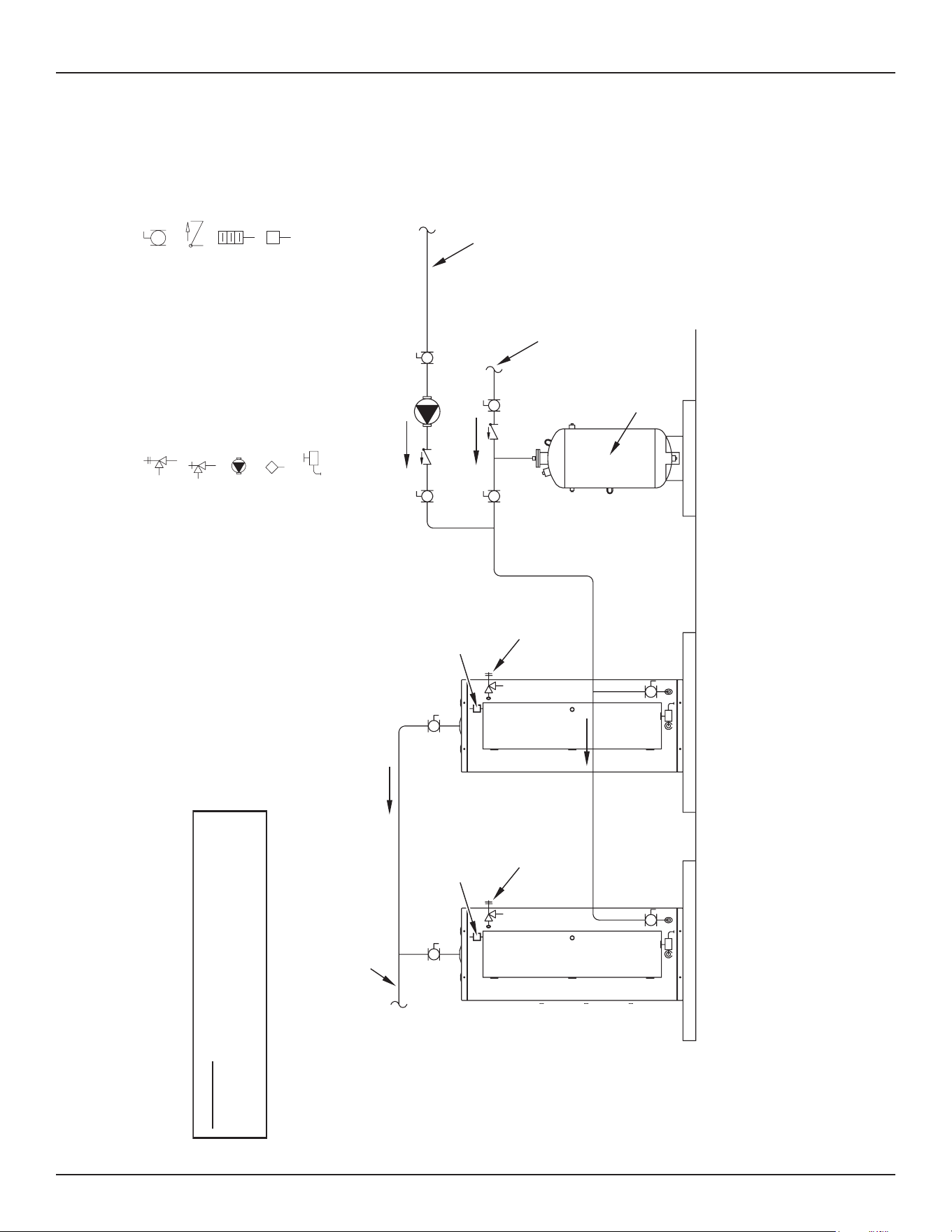
52 • Commercial Electric Water Heaters
Diagrams
NOTES:
1. Preferred piping diagram.
2. The temperature and pressure relief valve setting shall not exceed pressure rating of any component in the system.
3. Service valves are shown for servicing unit. However, local codes shall govern their usage.
COMMERCIAL ELECTRIC - (2 UNITS)
LEGEND
TEMPERATURE & PRESSURE
RELIEF VALVE
PRESSURE RELIEF VALVE
CIRCULATING PUMP
TANK TEMPERATURE CONTROL
DRAIN
FULL PORT BALL VALV
E
TEMPERATURE GAGE
WATER FLOW SWITCH
CHECK VALVE
WARNING: THIS DRAWING SHOWS SUGGESTED
PIPING CONFIGURATION AND OTHER DEVICES;
CHECK WITH LOCAL CODES AND ORDINANCES
FOR ADDITIONAL REQUIREMENTS.
EXPANSION
TANK
HOT WATER
RETURN
COLD WATER
SUPPLY
FUSED
DISCONNECT
SWITCH
PIPE T&P TO
OPEN DRAIN
FUSED
DISCONNECT
SWITCH
PIPE T&P TO
OPEN DRAIN
HOT WATER
TO FIXTURES
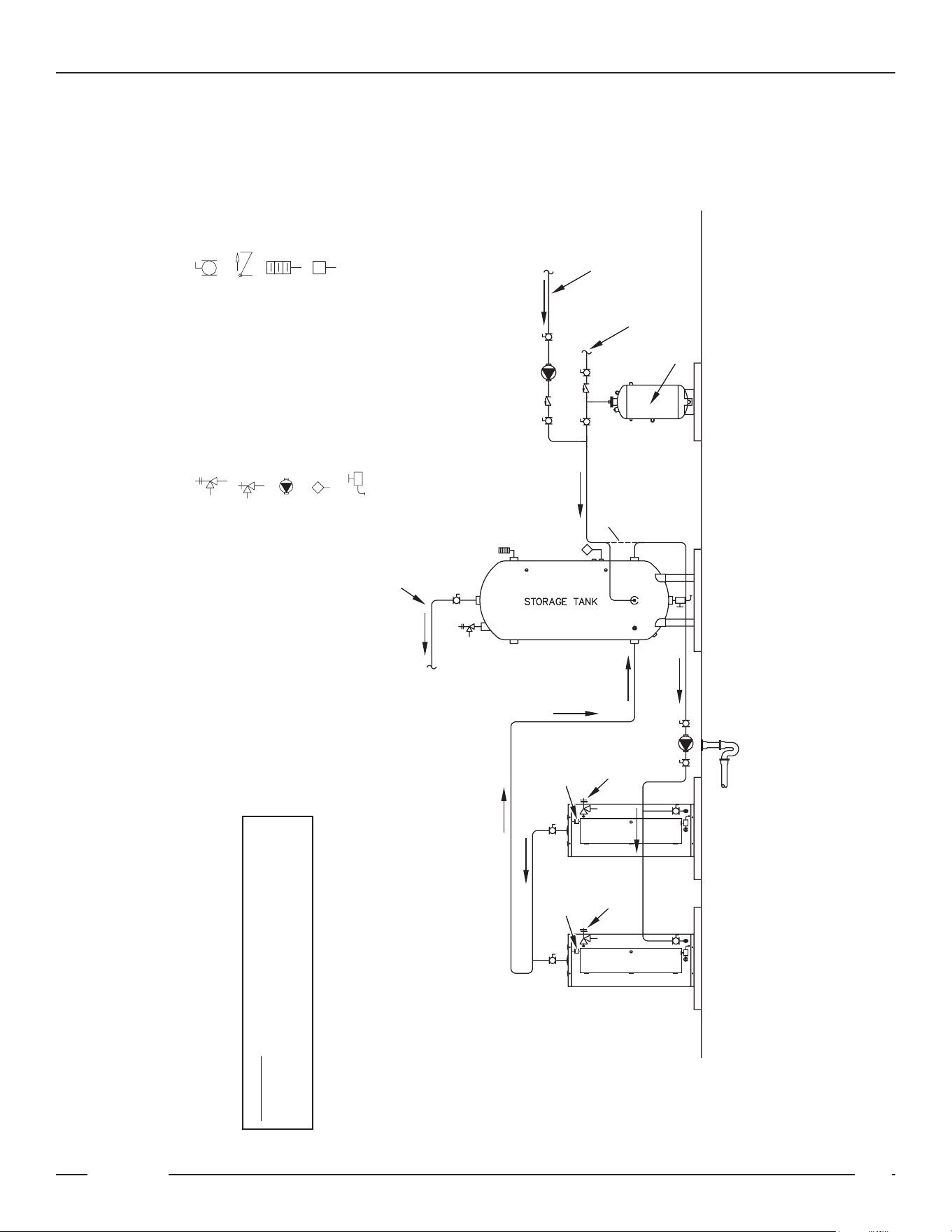
Diagrams
Commercial Electric Water Heaters • 53
October 2009 | Printed in U.S.A. | © A. O. Smith For Technical Information and Automated Fax Service, call 800-527-1953 or visit www.hotwater.com. AOSCE61050 | PAGE 1 of 1
A. O. Smith Corporation reserves the right to make product changes or improvements without prior notice.
NOTES:
1. Preferred piping diagram.
2. The temperature and pressure relief valve setting shall not exceed pressure rating of any component in the system.
3. Service valves are shown for servicing unit. However, local codes shall govern their usage.
4. The Tank Temperature Control should be wired to and control the pump between the water heater(s) and the storage tank(s).
5. The water heater’s operating thermostat should be set 5 degrees F higher than the Tank Temperature Control.
COMMERCIAL ELECTRIC - (2 UNITS) WITH VERTICAL STORAGE TANK
LEGEND
TEMPERATURE & PRESSURE
RELIEF VALVE
PRESSURE RELIEF VALVE
CIRCULATING PUMP
TANK TEMPERATURE CONTROL
DRAIN
FULL PORT BALL VALVE
TEMPERATURE GAGE
WATER FLOW SWITCH
CHECK VALVE
WARNING: THIS DRAWING SHOWS SUGGESTED
PIPING CONFIGURATION AND OTHER DEVICES;
CHECK WITH LOCAL CODES AND ORDINANCES
FOR ADDITIONAL REQUIREMENTS.
FINISHED
FLOOR
HOT WATER
TO FIXTURES
EXPANSION
TANK
ALT. COLD WATER
CONNECTION
HOT WATER
RETURN
COLD WATER
SUPPLY
FUSED
DISCONNECT
SWITCH
PIPE T&P TO
OPEN DRAIN
FUSED
DISCONNECT
SWITCH
PIPE T&P TO
OPEN DRAIN
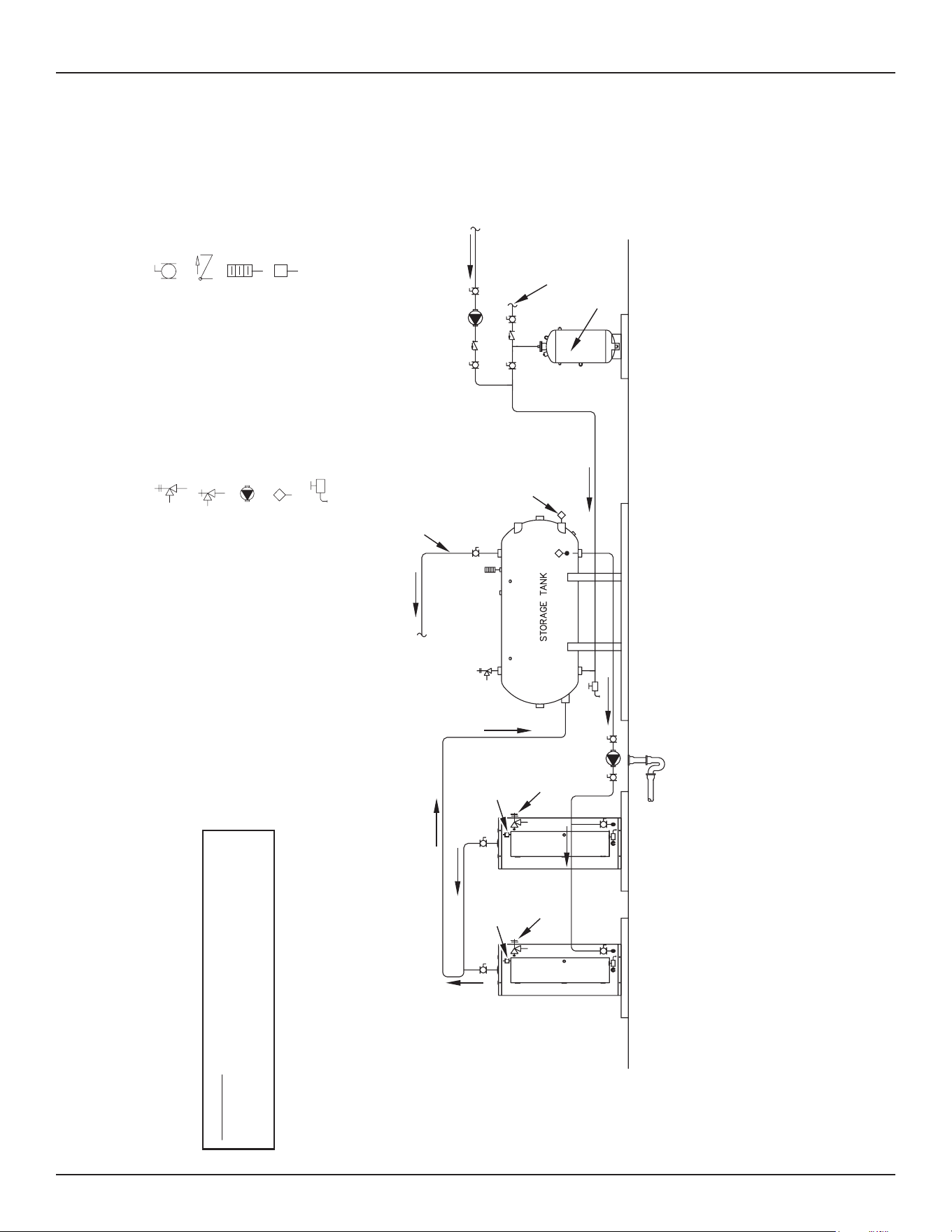
54 • Commercial Electric Water Heaters
Diagrams
October 2009 | Printed in U.S.A. | © A. O. Smith For Technical Information and Automated Fax Service, call 800-527-1953 or visit www.hotwater.com. AOSCE61060 | PAGE 1 of 1
A. O. Smith Corporation reserves the right to make product changes or improvements without prior notice.
NOTES:
1. Preferred piping diagram.
2. The temperature and pressure relief valve setting shall not exceed pressure rating of any component in the system.
3. Service valves are shown for servicing unit. However, local codes shall govern their usage.
4. The Tank Temperature Control should be wired to and control the pump between the water heater(s) and the storage tank(s).
5. The water heater’s operating thermostat should be set 5 degrees F higher than the Tank Temperature Control.
COMMERCIAL ELECTRIC - (2 UNITS) WITH HORIZONTAL STORAGE TANK
LEGEND
TEMPERATURE & PRESSURE
RELIEF VALVE
PRESSURE RELIEF VALVE
CIRCULATING PUMP
TANK TEMPERATURE CONTROL
DRAIN
FULL PORT BALL VALVE
TEMPERATURE GAGE
WATER FLOW SWITCH
CHECK VALVE
WARNING: THIS DRAWING SHOWS SUGGESTED
PIPING CONFIGURATION AND OTHER DEVICES;
CHECK WITH LOCAL CODES AND ORDINANCES
FOR ADDITIONAL REQUIREMENTS.
FINISHED
FLOOR
HOT WATER
TO FIXTURES
ALTERNATE
LOCATION
EXPANSION
TANK
HOT WATER
RETURN
COLD WATER
SUPPLY
FUSED
DISCONNECT
SWITCH
PIPE T&P TO
OPEN DRAIN
FUSED
DISCONNECT
SWITCH
PIPE T&P TO
OPEN DRAIN
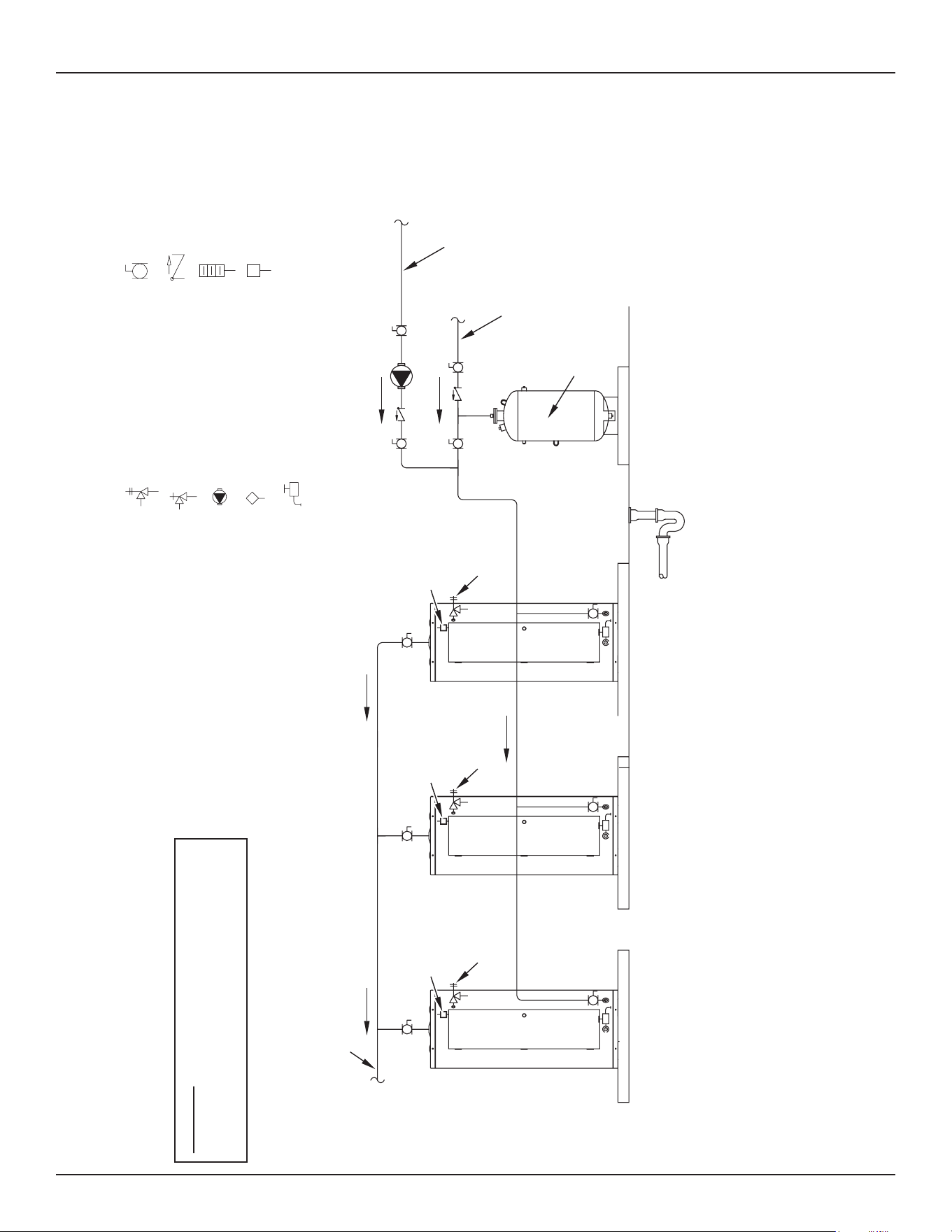
Diagrams
Commercial Electric Water Heaters • 55
NOTES:
1. Preferred piping diagram.
2. The temperature and pressure relief valve setting shall not exceed pressure rating of any component in the system.
3. Service valves are shown for servicing unit. However, local codes shall govern their usage.
COMMERCIAL ELECTRIC - (3 UNITS)
LEGEND
TEMPERATURE & PRESSURE
RELIEF VALVE
PRESSURE RELIEF VALVE
CIRCULATING PUMP
TANK TEMPERATURE CONTROL
DRAIN
FULL PORT BALL VALVE
TEMPERATURE GAGE
WATER FLOW SWITCH
CHECK VALVE
WARNING: THIS DRAWING SHOWS SUGGESTED
PIPING CONFIGURATION AND OTHER DEVICES;
CHECK WITH LOCAL CODES AND ORDINANCES
FOR ADDITIONAL REQUIREMENTS.
HOT WATER
TO FIXTURES
EXPANSION
TANK
HOT WATER
RETURN
COLD WATER
SUPPLY
FUSED
DISCONNECT
SWITCH
PIPE T&P TO
OPEN DRAIN
FUSED
DISCONNECT
SWITCH
PIPE T&P TO
OPEN DRAIN
PIPE T&P TO
OPEN DRAIN
FUSED
DISCONNECT
SWITCH
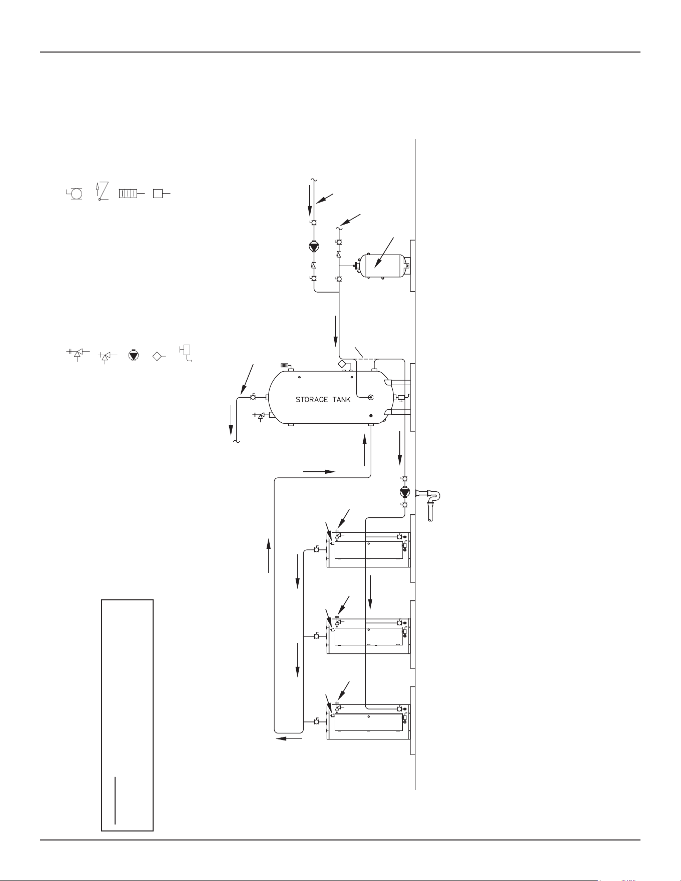
56 • Commercial Electric Water Heaters
Diagrams
NOTES:
1. Preferred piping diagram.
2. The temperature and pressure relief valve setting shall not exceed pressure rating of any component in the system.
3. Service valves are shown for servicing unit. However, local codes shall govern their usage.
4. The Tank Temperature Control should be wired to and control the pump between the water heater(s) and the storage tank(s).
5. The water heater’s operating thermostat should be set 5 degrees F higher than the Tank Temperature Control.
COMMERCIAL ELECTRIC - (3 UNITS) WITH VERTICAL STORAGE TANK
LEGEND
TEMPERATURE & PRESSURE
RELIEF VALVE
PRESSURE RELIEF VALVE
CIRCULATING PUMP
TANK TEMPERATURE CONTROL
DRAIN
FULL PORT BALL VALVE
TEMPERATURE GAGE
WATER FLOW SWITCH
CHECK VALVE
WARNING: THIS DRAWING SHOWS SUGGESTED
PIPING CONFIGURATION AND OTHER DEVICES;
CHECK WITH LOCAL CODES AND ORDINANCES
FOR ADDITIONAL REQUIREMENTS.
HOT WATER
TO FIXTURES
FINISHED
FLOOR
ALT. COLD WATER
CONNECTION
EXPANSION
TANK
HOT WATER
RETURN
COLD WATER
SUPPLY
FUSED
DISCONNECT
SWITCH
PIPE T&P TO
OPEN DRAIN
FUSED
DISCONNECT
SWITCH
PIPE T&P TO
OPEN DRAIN
FUSED
DISCONNECT
SWITCH
PIPE T&P TO
OPEN DRAIN
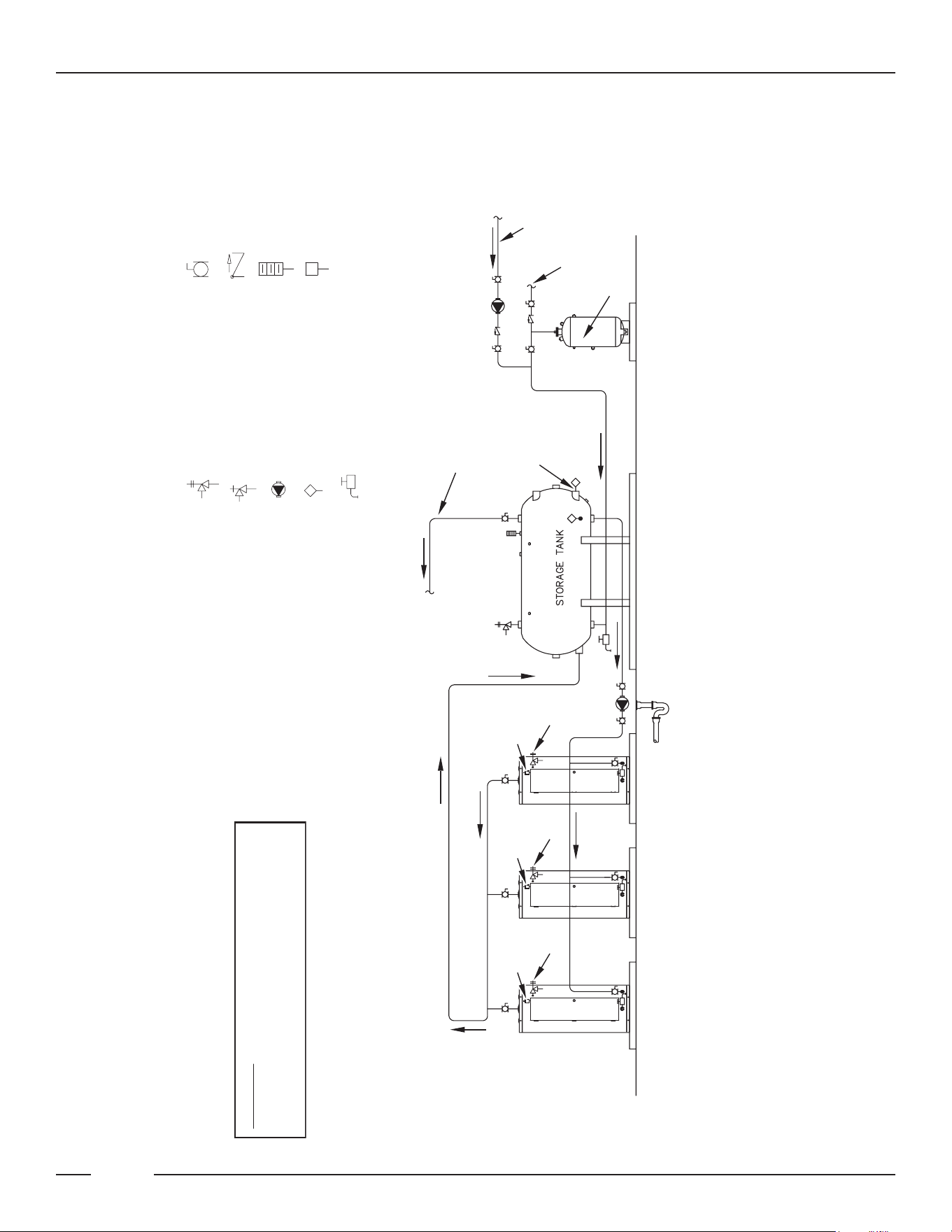
Diagrams
Commercial Electric Water Heaters • 57
October 2009 | Printed in U.S.A. | © A. O. Smith For Technical Information and Automated Fax Service, call 800-527-1953 or visit www.hotwater.com. AOSCE61090 | PAGE 1 of 1
A. O. Smith Corporation reserves the right to make product changes or improvements without prior notice.
NOTES:
1. Preferred piping diagram.
2. The temperature and pressure relief valve setting shall not exceed pressure rating of any component in the system.
3. Service valves are shown for servicing unit. However, local codes shall govern their usage.
4. The Tank Temperature Control should be wired to and control the pump between the water heater(s) and the storage tank(s).
5. The water heater’s operating thermostat should be set 5 degrees F higher than the Tank Temperature Control.
COMMERCIAL ELECTRIC - (3 UNITS) WITH HORIZONTAL STORAGE TANK
LEGEND
TEMPERATURE & PRESSURE
RELIEF VALVE
PRESSURE RELIEF VALVE
CIRCULATING PUMP
TANK TEMPERATURE CONTROL
DRAIN
FULL PORT BALL VALVE
TEMPERATURE GAGE
WATER FLOW SWITCH
CHECK VALVE
WARNING: THIS DRAWING SHOWS SUGGESTED
PIPING CONFIGURATION AND OTHER DEVICES;
CHECK WITH LOCAL CODES AND ORDINANCES
FOR ADDITIONAL REQUIREMENTS.
HOT WATER
TO FIXTURES
FINISHED
FLOOR
ALTERNATE
LOCATION
EXPANSION
TANK
HOT WATER
RETURN
COLD WATER
SUPPLY
FUSED
DISCONNECT
SWITCH
PIPE T&P TO
OPEN DRAIN
FUSED
DISCONNECT
SWITCH
PIPE T&P TO
OPEN DRAIN
FUSED
DISCONNECT
SWITCH
PIPE T&P TO
OPEN DRAIN
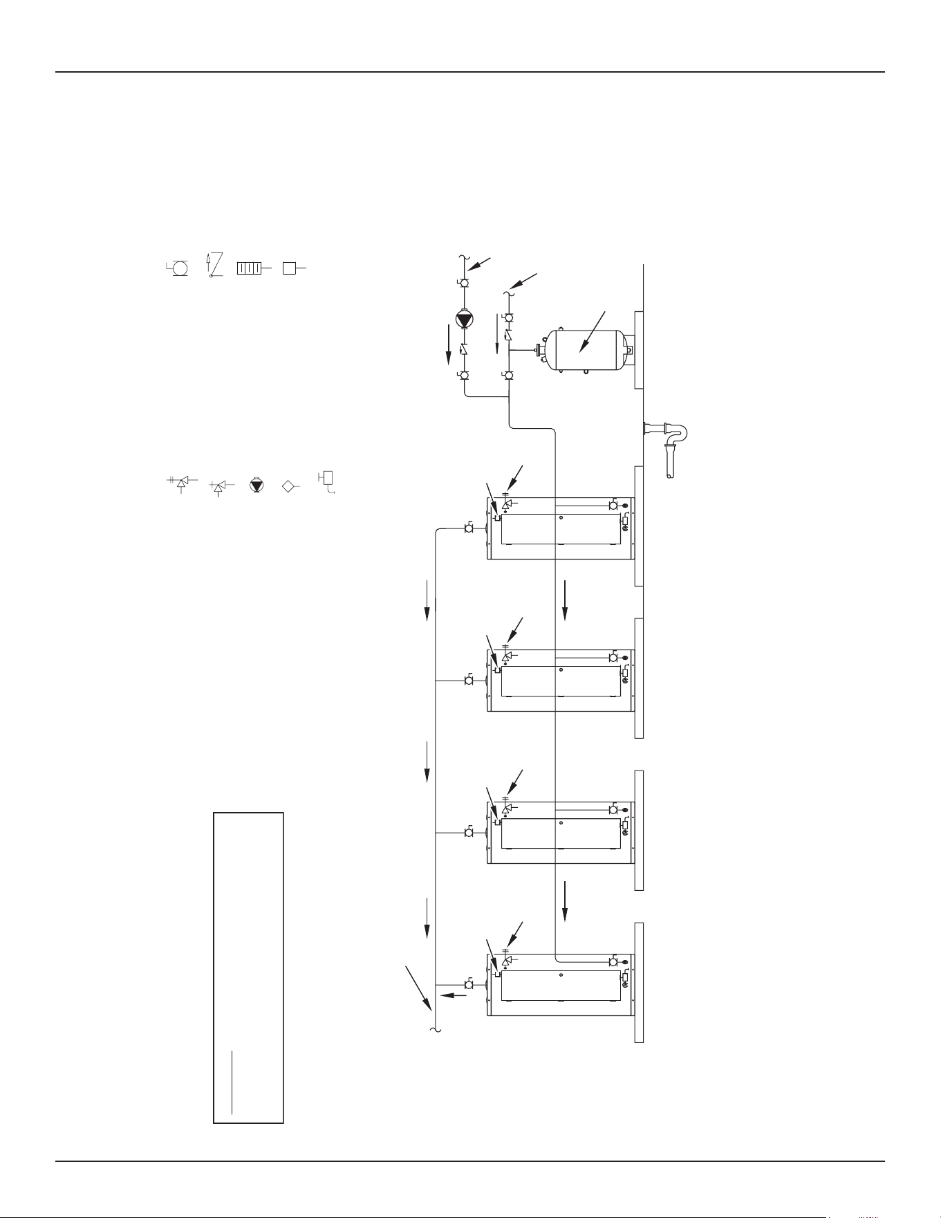
58 • Commercial Electric Water Heaters
Diagrams
October 2009 | Printed in U.S.A. | © A. O. Smith For Technical Information and Automated Fax Service, call 800-527-1953 or visit www.hotwater.com. AOSCE61100 | PAGE 1 of 1
A. O. Smith Corporation reserves the right to make product changes or improvements without prior notice.
NOTES:
1. Preferred piping diagram.
2. The temperature and pressure relief valve setting shall not exceed pressure rating of any component in the system.
3. Service valves are shown for servicing unit. However, local codes shall govern their usage.
COMMERCIAL ELECTRIC - (4 UNITS)
LEGEND
TEMPERATURE & PRESSURE
RELIEF VALVE
PRESSURE RELIEF VALVE
CIRCULATING PUMP
TANK TEMPERATURE CONTROL
DRAIN
FULL PORT BALL VALVE
TEMPERATURE GAGE
WATER FLOW SWITCH
CHECK VALVE
WARNING: THIS DRAWING SHOWS SUGGESTED
PIPING CONFIGURATION AND OTHER DEVICES;
CHECK WITH LOCAL CODES AND ORDINANCES
FOR ADDITIONAL REQUIREMENTS.
EXPANSION
TANK
HOT WATER
RETURN
COLD WATER
SUPPLY
FUSED
DISCONNECT
SWITCH
PIPE T&P TO
OPEN DRAIN
FUSED
DISCONNECT
SWITCH
PIPE T&P TO
OPEN DRAIN
FUSED
DISCONNECT
SWITCH
PIPE T&P TO
OPEN DRAIN
FUSED
DISCONNECT
SWITCH
PIPE T&P TO
OPEN DRAIN
HOT WATER
TO FIXTURES
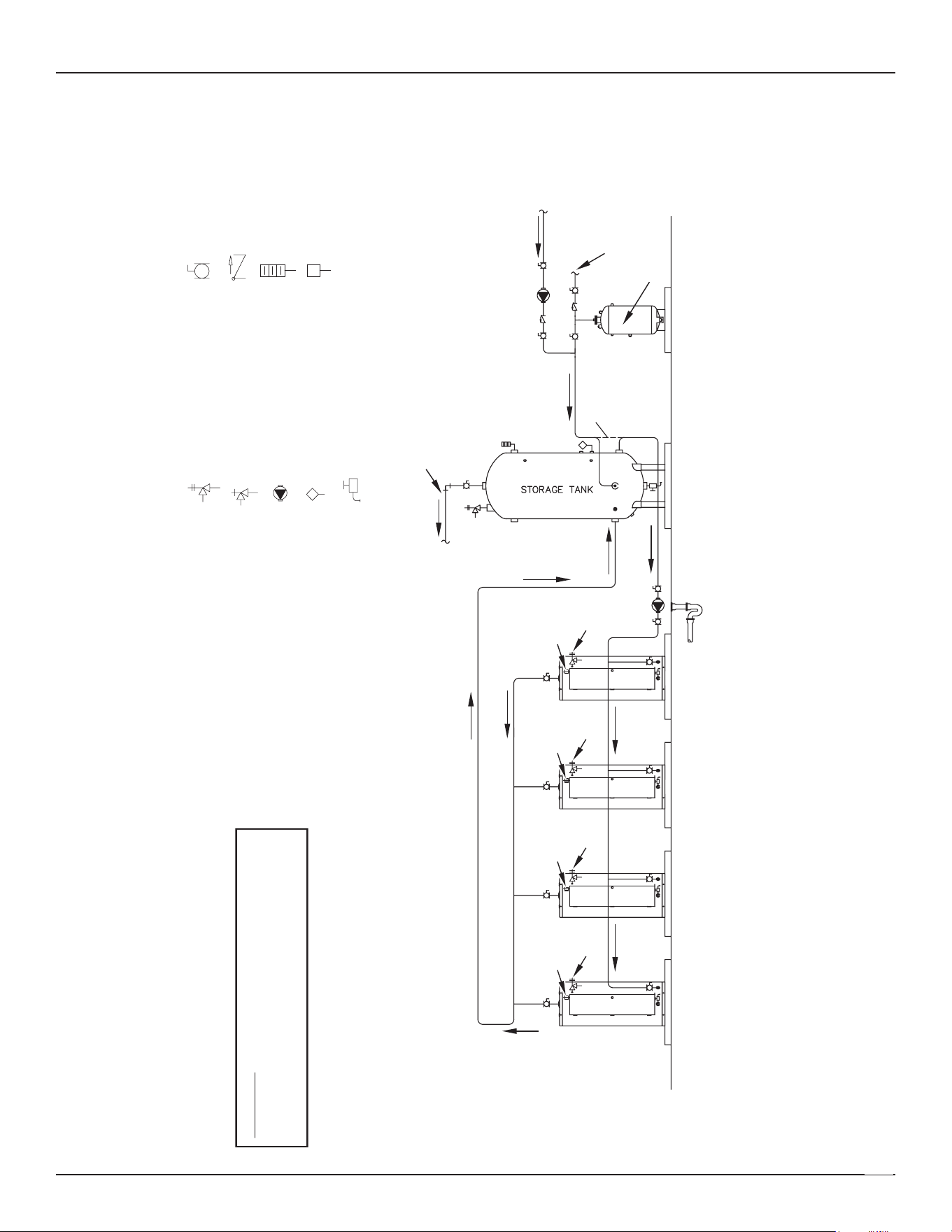
Diagrams
Commercial Electric Water Heaters • 59
October 2009 | Printed in U.S.A. | © A. O. Smith For Technical Information and Automated Fax Service, call 800-527-1953 or visit www.hotwater.com. AOSCE61110 | PAGE 1 of 1
A. O. Smith Corporation reserves the right to make product changes or improvements without prior notice.
NOTES:
1. Preferred piping diagram.
2. The temperature and pressure relief valve setting shall not exceed pressure rating of any component in the system.
3. Service valves are shown for servicing unit. However, local codes shall govern their usage.
4. The Tank Temperature Control should be wired to and control the pump between the water heater(s) and the storage tank(s).
5. The water heater’s operating thermostat should be set 5 degrees F higher than the Tank Temperature Control.
COMMERCIAL ELECTRIC - (4 UNITS) WITH VERTICAL STORAGE TANK
LEGEND
TEMPERATURE & PRESSURE
RELIEF VALVE
PRESSURE RELIEF VALVE
CIRCULATING PUMP
TANK TEMPERATURE CONTROL
DRAIN
FULL PORT BALL VALVE
TEMPERATURE GAGE
WATER FLOW SWITCH
CHECK VALVE
WARNING: THIS DRAWING SHOWS SUGGESTED
PIPING CONFIGURATION AND OTHER DEVICES;
CHECK WITH LOCAL CODES AND ORDINANCES
FOR ADDITIONAL REQUIREMENTS.
HOT WATER
TO FIXTURES
FINISHED
FLOOR
EXPANSION
TANK
HOT WATER
RETURN
COLD WATER
SUPPLY
ALT. COLD
WATER
CONNECTION
FUSED
DISCONNECT
SWITCH
PIPE T&P TO
OPEN DRAIN
FUSED
DISCONNECT
SWITCH
PIPE T&P TO
OPEN DRAIN
FUSED
DISCONNECT
SWITCH
PIPE T&P TO
OPEN DRAIN
FUSED
DISCONNECT
SWITCH
PIPE T&P TO
OPEN DRAIN
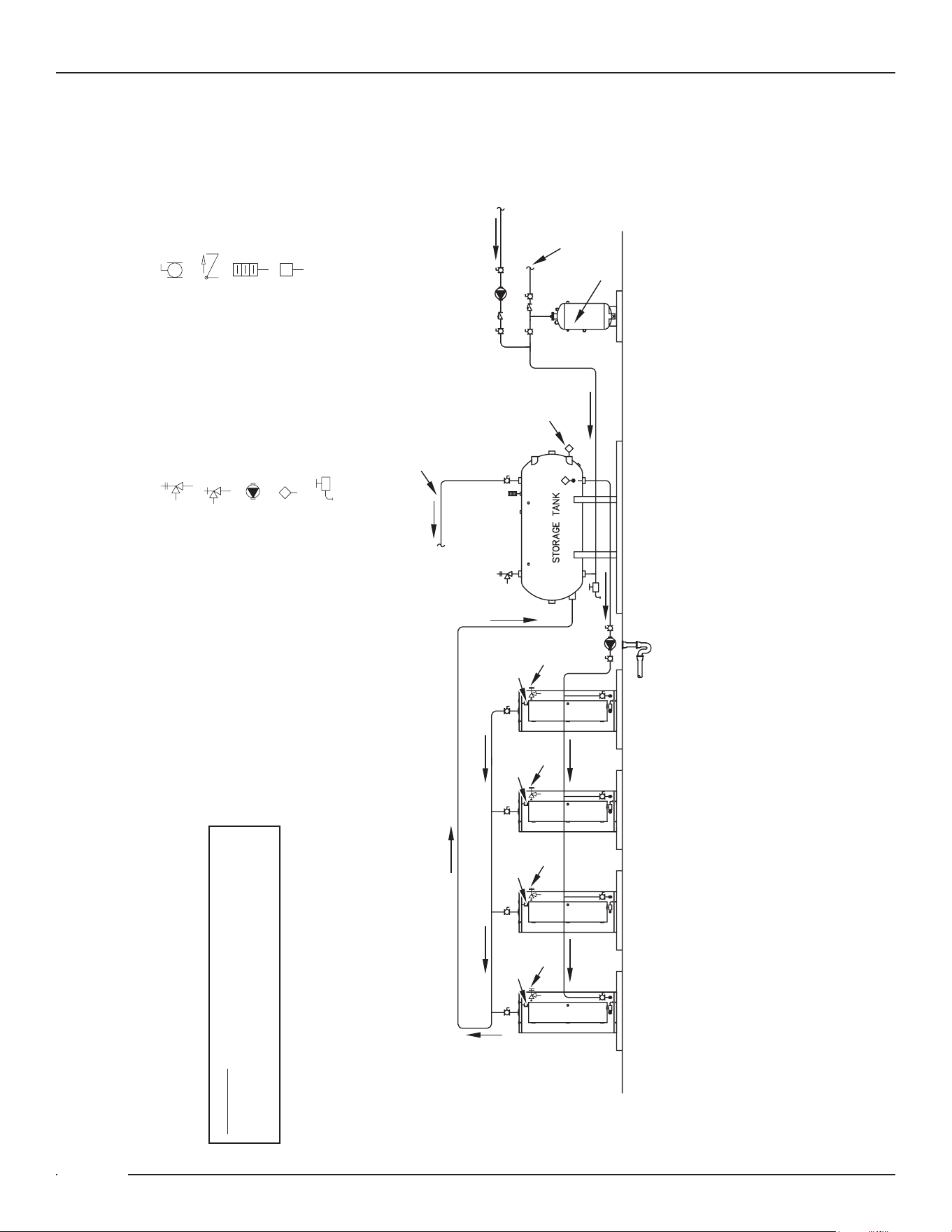
60 • Commercial Electric Water Heaters
Diagrams
October 2009 | Printed in U.S.A. | © A. O. Smith For Technical Information and Automated Fax Service, call 800-527-1953 or visit www.hotwater.com. AOSCE61120 | PAGE 1 of 1
A. O. Smith Corporation reserves the right to make product changes or improvements without prior notice.
NOTES:
1. Preferred piping diagram.
2. The temperature and pressure relief valve setting shall not exceed pressure rating of any component in the system.
3. Service valves are shown for servicing unit. However, local codes shall govern their usage.
4. The Tank Temperature Control should be wired to and control the pump between the water heater(s) and the storage tank(s).
5. The water heater’s operating thermostat should be set 5 degrees F higher than the Tank Temperature Control.
COMMERCIAL ELECTRIC - (4 UNITS) WITH HORIZONTAL STORAGE TANK
LEGEND
TEMPERATURE & PRESSURE
RELIEF VALVE
PRESSURE RELIEF VALVE
CIRCULATING PUMP
TANK TEMPERATURE CONTROL
DRAIN
FULL PORT BALL VALVE
TEMPERATURE GAGE
WATER FLOW SWITCH
CHECK VALVE
WARNING: THIS DRAWING SHOWS SUGGESTED
PIPING CONFIGURATION AND OTHER DEVICES;
CHECK WITH LOCAL CODES AND ORDINANCES
FOR ADDITIONAL REQUIREMENTS.
HOT WATER
TO FIXTURES
ALTERNATE
LOCATION
FINISHED
FLOOR
EXPANSION
TANK
HOT WATER
RETURN
COLD WATER
SUPPLY
FUSED
DISCONNECT
SWITCH
PIPE T&P TO
OPEN DRAIN
FUSED
DISCONNECT
SWITCH
PIPE T&P TO
OPEN DRAIN
FUSED
DISCONNECT
SWITCH
PIPE T&P TO
OPEN DRAIN
FUSED
DISCONNECT
SWITCH
PIPE T&P TO
OPEN DRAIN

Commercial Electric Water Heaters • 61
NOTES

62 • Commercial Electric Water Heaters
NOTES

Commercial Electric Water Heaters • 63
NOTES

300 Maddox Simpson Parkway
Lebanon, TN 37090
Technical Service Phone: 1-800-722-2101
Technical Service email: 2tech@lochinvar.com
www.Lochinvar.com
Copyright © 2024. All rights reserved.