
Dear Valued Customer,
Thank you for going with ARCCAPTAIN! We're all about making welders superior for you.
ARCCAPTAIN was built by high quality components, every single unit machine was passed
multiple industry leading laboratory tests to provide a great welding experience and
performance.
One-year warranty service is provide to yours! When unpacking, make sure that the
product is intact and undamaged. DO NOT return directly before contact our customer
service.
7 ways to connect us and join in ARCCAPTAIN Community:
Email: [email protected]
Online: www.arccaptain.com/pages/contact-us
Facebook: arccaptainwelder
Instagram: arccaptain_welder
Youtube: arccaptain-weld
Whatsapp: +19892449456
This manual is designed to help you get the most out of your ARCCAPTAIN products.
Please save this manual and take time to read the safety warnings and precautions,
assembly, operating, inspection, maintenance. They will help you protect yourself against
potential hazards on the worksite. Failure to do so can result in serious injury!
Save for future reference:
Product
:
Date Purchased:
Serial Number:
Product Feedback:


CONTENTS
1. SAFETY ..................................................................................................................................... 1
1.1 General Safety .......................................................................................................................1
1.2 Electrical Safety .................................................................................................................... 1
1.3 Fire Safety ..............................................................................................................................1
1.4 Fumes and Gases Safety ..................................................................................................... 2
1.5 Arc Rays and Noice Safety .................................................................................................. 2
1.6 Gas Shielded Welding – Cylinder Safety ........................................................................... 2
1.7 Additional Safety Information..............................................................................................3
2. PRODUCT INSTRUCTION ....................................................................................................... 3
2.1 Function Overview ................................................................................................................3
2.2 Package ..................................................................................................................................3
2.3 Technical Parameters ...........................................................................................................4
3. OPERATION CONTROL AND INSTRUCTIONS ......................................................................5
3.1 Panel Instruction ...................................................................................................................5
3.2 Multi-function Digital Operation Description .....................................................................6
3.3 Wire Feeding Description .................................................................................................... 9
1. Feed Tensioner........................................................................................................................9
Fixed the Idler Arm and adjusts the pressure on the wire .....................................................9
Figure 7 Inside wire feeder ......................................................................................................9
2.Idler Arm ....................................................................................................................................9
Press down on the welding wire............................................................................................... 9
3. Wire Inlet Liner ........................................................................................................................ 9
Guide the welding wire into the wire feeder ............................................................................ 9
4. Feed Roller ...............................................................................................................................9
V0.8-0.9 feed roller,Transfer welding wire ................................................................................9
5. Wire Spool ............................................................................................................................... 9
Fixed welding wire spool ........................................................................................................... 9
4. INSTALLATION AND CONNECTION .....................................................................................10
4.1 Selecting the Welding Wire ................................................................................................10
4.2 Checking the Torch Accessories ...................................................................................... 10
4.3 Installing the Welding Wire ................................................................................................11
4.4 Wire Feeding Installation ................................................................................................... 12
5. OPERATION FOR MIG AND FLUX CORED WELDING ....................................................... 14
5.1 Connection For Flux Cored Welding ................................................................................14
5.2 Connection For MIG/MAG Welding...................................................................................14
5.3 Input Power Connection .................................................................................................... 15
5.4 Wire Stick Out ..................................................................................................................... 16
5.5 Operation ............................................................................................................................. 17
6. Operation for Spool gun(Not Included) ...............................................................................18
6.1 Set Up Spool gun ................................................................................................................18
6.2 Connection .......................................................................................................................... 19
6.3 Input Power Connection .................................................................................................... 20

6.4 Operation ............................................................................................................................. 21
7. Operation for MMA and TIG .................................................................................................. 22
7.1 MMA Welder Cable Connection ........................................................................................ 22
7.2 MMA Welder Operation ...................................................................................................... 23
7.3 Lift TIG Welder Cable Connection(Not Included) ............................................................24
7.4 Lift tig Welder Operation ....................................................................................................26
8. Engineer Mode ....................................................................................................................... 28
8.1 Setting of system parameters ........................................................................................... 28
9. MIG Basic Welding Technique ..............................................................................................29
9.1 Basic MIG Welding ..............................................................................................................29
9.2 Feeding Speed .................................................................................................................... 31
10. MAINTENANCE .................................................................................................................... 32
10.1 Routine and Periodic Maintenance .................................................................................32
10.2 Daily maintenance ............................................................................................................ 33
11. TROUBLESHOOTING .......................................................................................................... 34
1
1. SAFETY
! WARINING READ ALL SAFETY WARNINGS BEFORE WORKING!
Failure to follow the warnings and instructions may result in electric shock, fire and/or
serious injury. Save all warnings and instructions for future reference!
If you encounter any issues during installation or operation, refer to the relevant sections in this
manual for inspection. If you're still unsure or unable to resolve the problem, please contact
ARCCAPTAIN professional support.
1.1 General Safety
Do NOT use the welder if the switch does not turn it on and off.
Disconnect the plug from the power source before making any adjustments, changing
accessories, or storing the welder.
Ensure the switch is off before connecting to power or moving the welder to prevent
accidental starting.
Always maintain and use safety guards, covers, and devices properly.
Keep hands, hair, clothing, and tools away from moving parts like V-belts, gears, and fans.
Follow these instructions and consider working conditions when using the welder and
accessories.
This manual may not cover every possible situation. It's important for the operator to use
common sense and caution while using this product.
1.2 Electrical Safety
! WARINING BEWARE OF ELECTRIC SHOCK!
DO NOT weld in a damp area or come in contact with a moist or wet surface.
DO NOT modify any wiring, ground connections, switches, or fuses in this welding
equipment.
DO NOT come into physical contact with any part of the welding current circuit, including
the workpiece, ground clamp, electrode or welding wire, and metal parts on the electrode
holder or MIG gun.
DO NOT connect the ground clamp to electrical conduit, and DO NOT weld on electrical
conduit.
NEVER leave the Welder unattended while energized. Turn off the power if you have to
leave.
DO NOT attempt to plug the welder into the power source if the ground prong on INPUT
POWER CABLE plug is bent over, broken off, or missing.
DO NOT alter INPUT POWER CABLE or plug in any way.
People with pacemakers should consult their physicians before use. Magnetic field can
make cardiac pacemaker a bit wonky.
! WARINING REPLACING COMPONENTS CAN BE DANGEROUS!
Only experts should replace machine parts. Avoid dropping foreign objects into the
machine during component replacement. Ensure correct wire connections after replacing
PCBs to prevent property damage.
1.3 Fire Safety
! WARINING BEWARE OF FIRE HAZARD!
Place the machine on non-combustible surfaces to prevent fires.
2
Ensure no flammable materials are near the working area to reduce fire risk.
Avoid installing the machine near water sources to prevent water damage.
Always weld/cut materials in a dry environment with humidity below 90% and maintain a
working temperature between -10°C and 40°C.
When welding/cutting outdoors, ensure shelter from sunlight and rain, keeping the
machine dry at all times.
Do not operate the machine in dusty or chemically corrosive environments.
Remove or secure all combustible materials within a 35 feet (10 meters) radius of the work
area. Use fire-resistant material to cover or seal open doorways, windows, cracks, and other
openings.
Improper use can lead to fire or explosion. Avoid flammable materials near the working
area, keep a fire extinguisher nearby with trained personnel, refrain from cutting closed
containers, and do not use the machine for pipe thawing.
1.4 Fumes and Gases Safety
! WARINING SMOKE CAN BE HARMFUL TO YOUR
HEALTH!
Keep your head away from the smoke while cutting to avoid breathing in harmful gases.
Ensure the working area is well-ventilated with exhaust or ventilation equipment during
cutting.
Only work in a confined area if it's well-ventilated, or wear an air-supplied respirator.
1.5 Arc Rays and Noice Safety
! WARINING
Arc radiation can harm eyes and skin; excessive noise can damage hearing.
Use certified welding eye protection with at least a number 10 shade lens rating.
Wear leather leggings and fire-resistant shoes or boots; avoid clothing that can catch
sparks or molten metal. Do not touch hot workpiece with bare hands.
Keep clothing free of flammable substances and wear dry, insulating gloves and
protective clothing.
Wear an approved head covering and use appropriate welding attire.
When welding overhead or in confined spaces, use flame-resistant ear plugs or ear muffs.
Wear ear covers or other hearing protectors when cutting.
1.6 Gas Shielded Welding – Cylinder Safety
! WARINING CYLINDERS CAN EXPLODE WHEN
DAMAGED!
Never weld on a pressurized or closed cylinder.
Avoid letting the electrode holder, electrode, welding torch, or welding wire touch the
cylinder.
Keep cylinders away from all electrical circuits, including welding circuits.
Always keep the protective cap on the valve except when the cylinder is in use.
Use only the correct gas shielding equipment designed for your specific type of welding,
and maintain it properly.
Protect gas cylinders from heat, physical damage, slag, flames, sparks, and arcs.
EXCESSIVE NOISE DOES GREAT HARM TO HEARING!
ARC RADIATION MAY HURT YOUR EYES AND BURN YOUR SKIN!
3
Always follow proper procedures when moving cylinders.
Do not install the machine in an environment with explosive gas to avoid an explosion.
1.7 Additional Safety Information
Use only the supplied power cord for this welder or an identical replacement cord. Do not
install a thinner or longer cord on this Welder.
Maintain labels and nameplates on the Welder. These carry important information.
Ensure the ground clamp is securely connected to the workpiece during welding.
Pressing the gun switch when welding or cutting.
When disposing of the cutting machine, please note the following:
Burning electrolytic capacitors on the main circuit or PCB board may cause explosions.
Burning plastic components such as the front panel may produce toxic gases. Dispose of it
as industrial waste.
2. PRODUCT INSTRUCTION
2.1 Function Overview
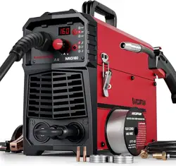
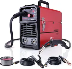
This is MIG200P, with advanced technology, perfect function and high performance. This ultra-portable
welding system is suitable for various application needs.
Multi-functions: Gas MIG/Gasless MIG/Pulse MIG/MMA /TIG/Spot welding/Spool Gun are available.
Synergic: Automatic matching by adjusting wire/rod diameter, material.
Accurate Preset Parameter: 9 groups parameter can be set and storage.
2T/4T: Realize wide application, easy welding and continuous long-term welding.
Inductance Adjustment: Improve welding performance.
Burn Back Adjustment: You could set burn-back time in MIG.
Hot Start: Make the arc ignition in MMA welding easier and more reliable.
Arc Force: Obviously improve the performance of the machine contribute to long-distance welding.
VRD: Reduce the risk of electric shock to ensure operator’s safety.
2.2 Package
Name
Specification
Quantity (pcs)
Welding machine
MIG200P
1
MIG welding torch
10ft
1
Torch accessories
Conduct tips
2
Ground clamp
10ft
1
Electrode holder
10ft
1
Gas hose
10ft
1
Adapter
220V to 110V
1
Rollers
/
3
4
Operator’s manual
For MIG200P
1
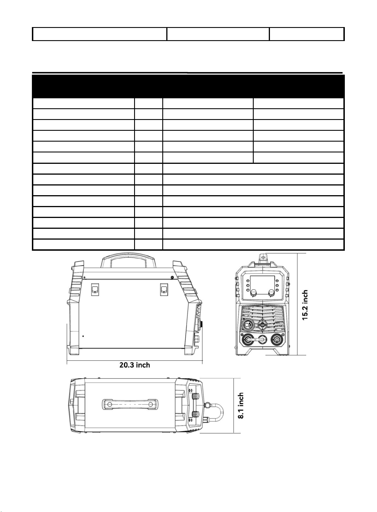
2.3 Technical Parameters
Technical Parameter
Units
Model
MIG200P
Rated input voltage
V
AC110V±15% 50/60HZ
AC220V±15% 50/60HZ
Rated input power
KVA
4.9
7.0
Rated input current
A
40.7
31.1
Welding current range (MMA)
A
20--140
20--200
Welding current range (TIG)
A
20--140
20--200
Welding voltage range (MIG)
A
30--140
30--200
Open circuit voltage
V
U
0
: 62 U
r
:12.5
Overall efficiency
%
85
Enclosure class
IP
21S
Power factor
COSφ
0.72
Insulation class
H
Standard
ANSI/NEMA/IEC 60974-1
Noise
db
<70
Dimension
inch
20.3x8.1x15.2
Figure 1 Size
5
3. OPERATION CONTROL AND INSTRUCTIONS
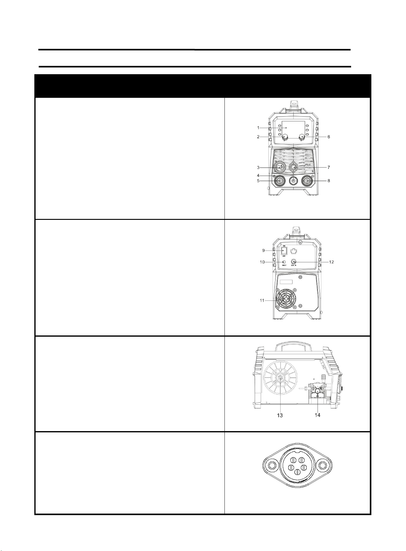
3.1 Panel Instruction
Part
Picture
1. Digital screen display area
2. Current and wire feed speed adjustment knob
3. Euro connector for torch
4. Polarity changeover plug
5. "+" output terminal
6. Voltage and spot welding time adjustment knob
7. Socket
8. "-" output terminal
9. Power switch
10. Input power cable
11. Cooling Fan
12. Gas inlet
13. Spool holder
14. Wire feeding unit
PIN 1: power source +
PIN 2: power source -
PIN 3: Remote control potentiometers 3 pin
PIN 4: Remote control potentiometers 2 pin
PIN 5: Remote control potentiometers 1 pin
1
2
3
4
5
Figure 2
Figure 3
Figure 4
Figure 5 Socket
6
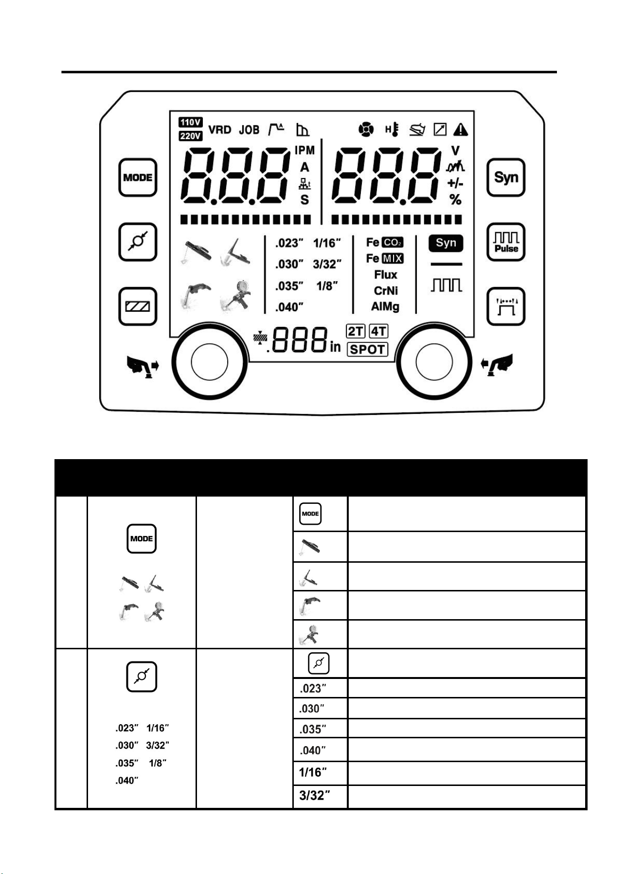
3.2 Multi-function Digital Operation Description
Figure 6 operation panel
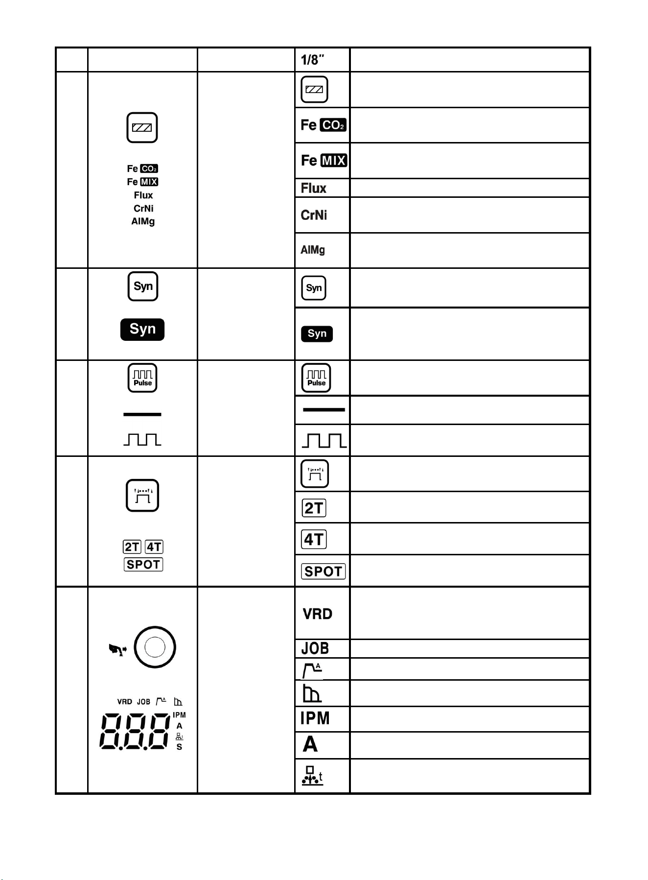
Detailed description for operation panel functions:
NO
.
Picture
Description
Item
Function
5
+
Welding
process
selection area
Welding process selection button
MMA Mode
Lift TIG Mode
MIG Mode
MIG spool gun Mode
7
+
Diameter
selection area
Diameter selection button
Φ0.023 inch diameter
Φ0.030 inch diameter
Φ0.035 inch diameter
Φ0.040 inch diameter
1/16 inch diameter
3/32 inch diameter
7
1/8 inch diameter
8
+
MIG material
selection area
Material selection button
Steel(carbon steel) + CO
2
100%
+ER50S-6/ER70S-6
Steel(carbon steel) + Ar80% CO
2
20%
+ER50S-6/ER70S-6
FCAW+gasless+E71T-GS
CrNi(stainless steel) + Ar98% CO
2
2% +
ER308
AlMg(Aluminum-magnesium alloy) +
Ar100% + ER5356
4
+
Synergic
selection
Switch button for “synergic” and
“separated”
MIG “synergic”LED
The LED is on when the machine is in
“synergic” *
+
Pulse
selection
Pulse switch in MIG mode
DC welding in MIG mode
Pulse welding in MIG mode
6
+
MIG operation
mode
selection area
MIG operation mode selection button
2T operation mode
4T operation mode
Spot welding mode
9
+
Left
adjustment
knob
VRD in MMA mode
Long press the 2T/4T button to turn on
and off VRD
Parameter group LED*
Hot start in MMA mode
Arc force in MMA mode
MIG Wire feeding speed
:
inch/min
Welding output current
MIG Bum-back time
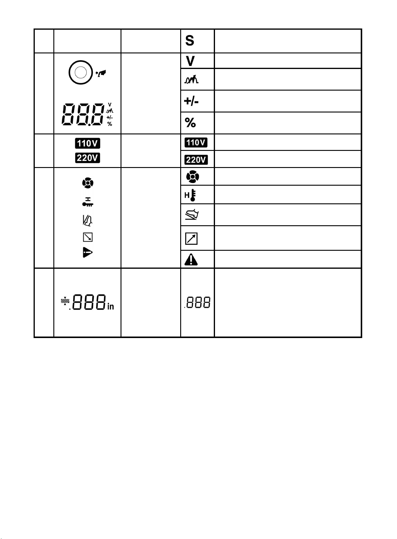
8
Spot welding time
+
Right
adjustment
knob
Welding voltage
Arc inductance, recommended to be set to
0
Subtle adjustment on welding voltage in
MIG “synergic”mode
MMA mode arc force and hot start
percentage display
Input voltage
The input voltage is 110V
The input voltage is 220V
The cooling fan is running
Welding machine overheating reminder
The welding machine has been connected
to the foot switch
The welding machine has been connected
to the spool gun control
Welding machine error reminder
Thickness of
the workpiece
The thickness of the workpiece suitable for
welding under the current output
Note:This parameter is only for general
reference, and the actual suitable
thickness of the workpiece depends on
the user's usage situation
* MIG welding mode “Synergic” and “separated”
There are two MIG/MAG welding mode, “synergic” and “separated”, for welding specification
adjustment:
Synergic: Current and voltage settings vary with different welding wire, wire diameter and gas; and
also at the same welding current, wire feed speed and synergic voltage may differ; the welder will
auto-match preset current and welding voltage, and users can adjust the inductance to the standard
position according to the process requirements,This MIG mode is suitable for unskilled welders.
Separated: No relation between wire feed speed and voltage adjustment, and users need to set
values separately, This MIG model is suitable for skilled welders.
* Parameter group
“JOB”, function of parameter group storage and usage, is in support of ten parameter group
storage“CH0~CH9” with one group covering all adjustable parameters on the machine panel, including
welding mode and the related conditions and settings. Press left encoder knob until the “JOB” LED
lights up and adjust the left encoder knob to select the parameter group. If the parameter group has
9
been saved on the current channel. The right LED screen will display the number 1/2/3/4(The number 1
-> MIG mode, 2 -> MIG spool gun mode, 3 -> TIG mode, 4 ->MMA mode).Otherwise the LED will display
“0”,which means no parameter group is currently saved, the parameter group will automatically save the
adjusted parameters(save after keeping the same parameters for 10S).The parameter group keeps the
last used parameters when the machine is turned on again. .It is easy to use parameter group, adjust left
encoder to select a channel with a saved parameter set, and press the right encoder knob to use it.
Attention
Attention! Please select welding functions according to welding requirements.
During welding, choose proper welding process and parameters according to
the technology requirements of workpiece. With improper welding process
and parameters, there will be unstable arc, excessive spatter and wire and
electrode sticking during welding.
Current display shows actual welding current, while voltage display shows actual welding voltage during
welding. Below is display in standby:
Welding process
Voltage display
Current display
MMA
Open circuit voltage or
VRD voltage(V)
Preset current value(A)
TIG
Open circuit voltage or
VRD voltage(V)
Preset current value(A)
MIG
Preset voltage value(V)
Preset wire feed speed(inch/min)
※During MIG welding, actual welding current is displayed when current knob is not rotated, preset wire
feed speed is displayed when current knob is rotated.
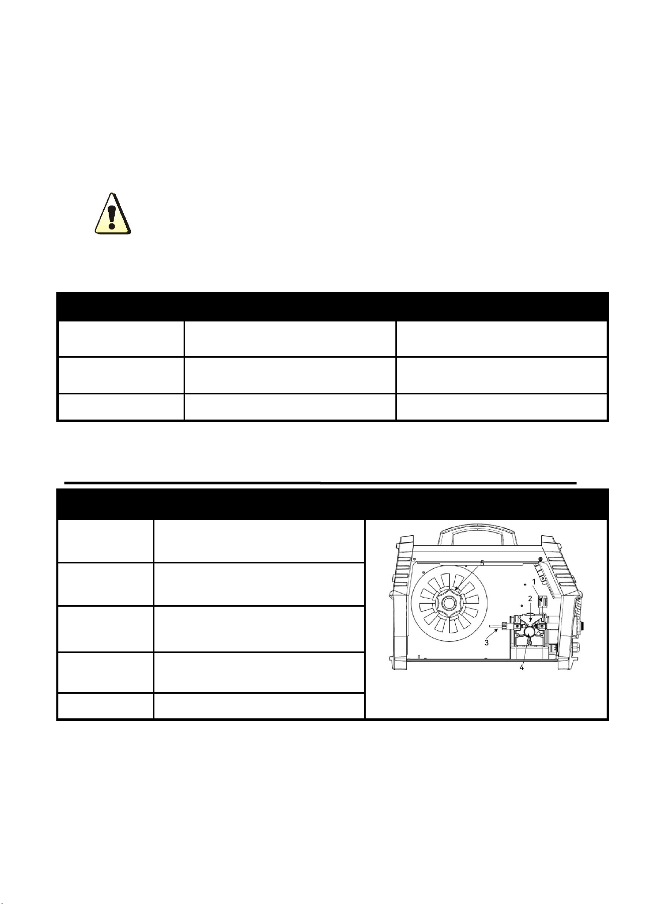
3.3 Wire Feeding Description
Part name
Function
Picture
1. Feed
Tensioner
Fixed the Idler Arm and adjusts the
pressure on the wire
Figure 7 Inside wire feeder
2.Idler Arm
Press down on the welding wire
3. Wire Inlet
Liner
Guide the welding wire into the wire
feeder
4. Feed Roller
V0.8-0.9 feed roller,Transfer welding
wire
5. Wire Spool
Fixed welding wire spool
10
4. INSTALLATION AND CONNECTION
! WARINING BEWARE OF ELECTRIC SHOCK!
Check and follow the instructions listed in the “Safety” section of this manual.
! WARINING DO NOT set up without SWITCH OFF !
4.1 Selecting the Welding Wire
This welder is compatible with 2lb or 10lb spools of 0.023", 0.030", 0.035", or 0.040" MIG
wire. Using thicker wire will not improve welding performance on thicker materials, nor will it
increase deposition rate. Additionally, it may strain your AC power source.
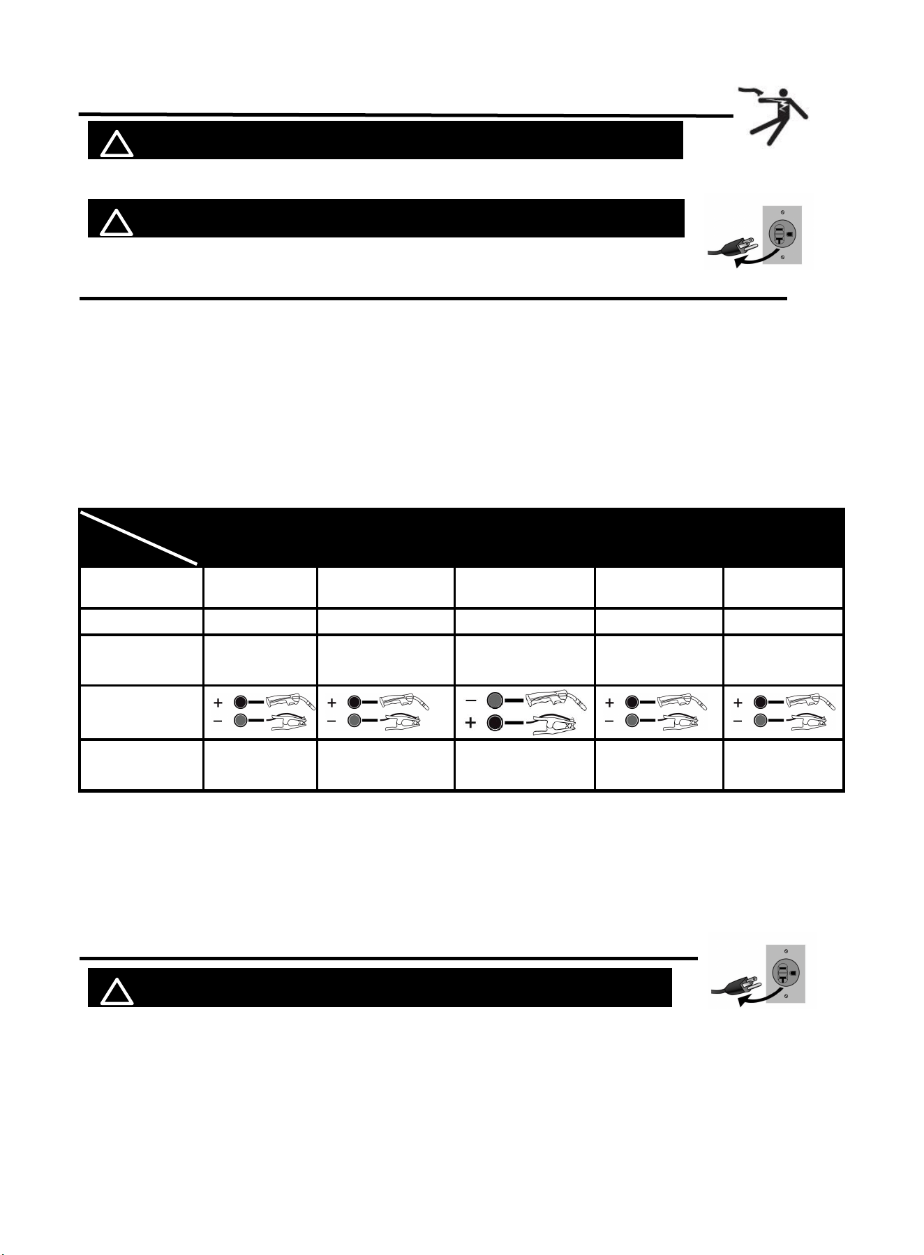
Matching table of relation between welding wire, diameter, shielding gas, material
and wire feeding roll
:
In synergic mode, different welding wire, diameter, shielding gas, material and wire feeding roll have
corresponding matching relationship as below table. Please select correct settings to achieve optimal
welding performance.
Function
Item
Fe CO
2
Fe MIX
Flux
CrNi
AlMg
MATERIAL
STEEL
STEEL
FLUX CORED
STAINLESS
ALUMINIUM
WIRE TYPE
ER70S-6
ER70S-6
E71T-GS
ER308
ER5356
DRIVE
ROLLER
V GROOVE
V GROOVE
KNURLED
V GROOVE
U GROOVE
POLARITY
GAS TYPE
100%CO
2
20%CO
2
+80%A
r
NO GAS
2%CO
2
+98%A
r
100%Ar
NOTE: Oxidized welding wire can affect welding results.
If you find rust on a wire spool, it's best to throw it away. But before you do, unwind a bit of
wire to see if the rest is still good. If it's also rusty, get rid of the whole spool.
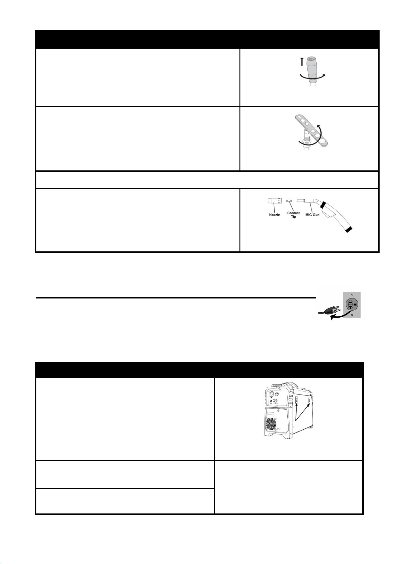
4.2 Checking the Torch Accessories
! WARINING DO NOT set up without SWITCH OFF !
Before welding, verify that the contact tip size in your MIG torch matches your welding wire
type. Do as following steps.
11
Description
Picture
1. Rotate counterclockwise to remove the nozzle.
Figure 8
2.Rotate counterclockwise to remove the contact tip.
Figure 9
3.Checking the size number on the contact tip. If not confirmed with your welding wire, change it.
4. Replace the nozzle and Contact Tip in clockwise.
Figure 10
4.3 Installing the Welding Wire
NOTE: Turn machine power switch to the OFF position before
working inside the wire feed enclosure. Make sure that the wire feed
drive roll and the contact tip of the gun match the diameter and type of wire used.
NOTE: DO NOT unhook leading end of the wire! It will prevents scattering the entire
coil of wire.
Description
Picture
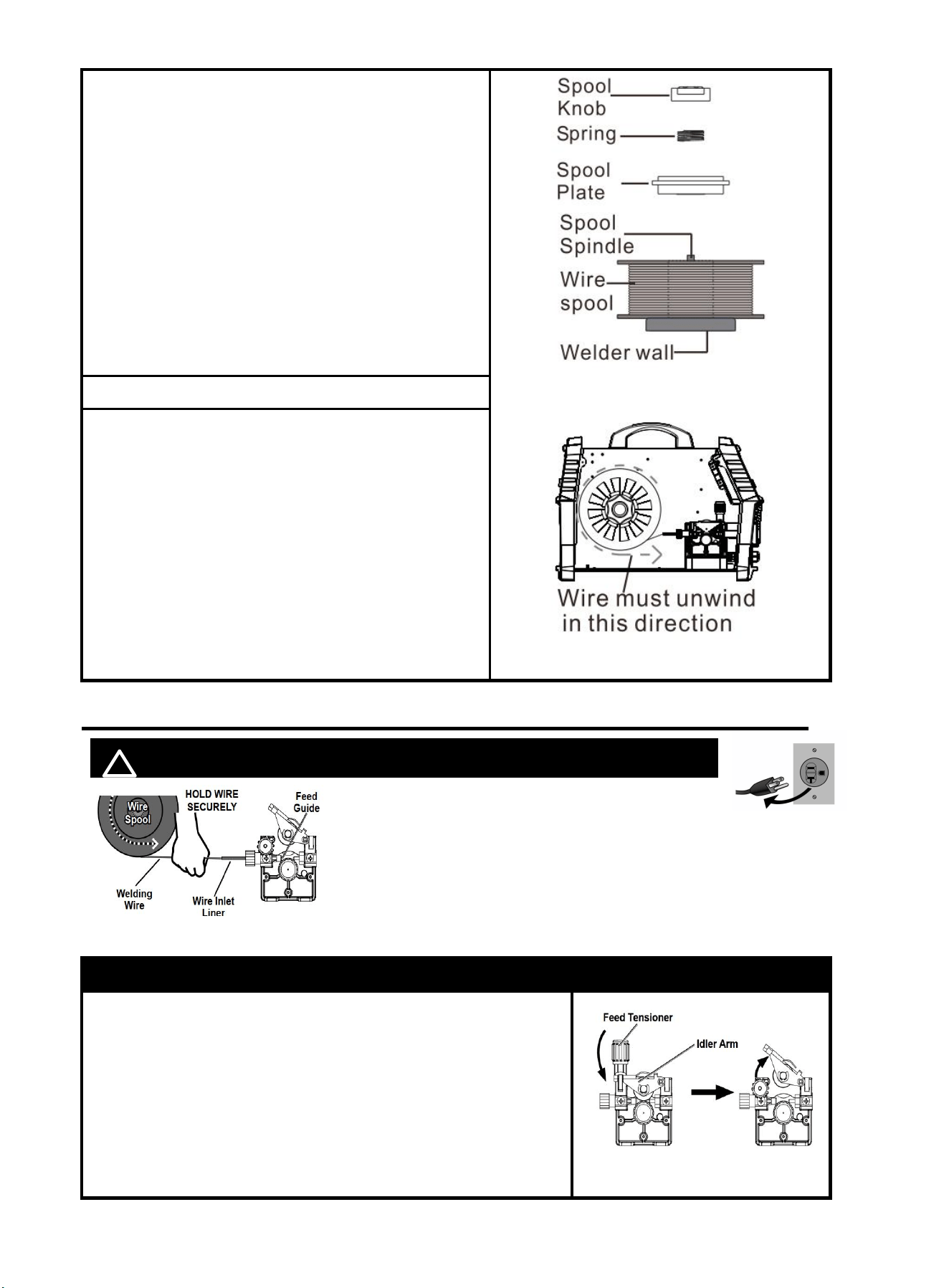
1.Pull up on the Door Latch, then open the Door.
Then you will see Wire Spool and wire feeder.
Figure 11 Door latch
2. Start to install the wire:
Turn counterclockwise to remove the spool knob.
3.Remove the spool plate, then spool spindle will be
exposed.
12
Figure 12 Wire spool
4.Place the wire spool over the spool spindle.
NOTICE:
To prevent wire feed problems, set the leading
end of spool wire towards to wire inlet liner (refer
to the picture), so that it will unwind
counterclockwise.
NOTICE:
To prevent welding wire to unravel and unspool
which can cause tangling and feeding problems,
DO NOT release the wire before spool knob
replace.
5.Replace the spool plate back on the spool spindle.
6. 6.Replace the spring and spool knob over the spool
plate, then turn the spool knob clockwise to tighten.
NOTICE:
If Wire Spool can spin freely, Knot is too loose.
This will cause the welding wire to unravel and
unspool which can cause tangling and feeding
problems.
4.4 Wire Feeding Installation
! WARINING DO NOT set up without SWITCH OFF !
NOTE: MUST Securely hold onto the end
of the welding wire and keep tension on it during the
following steps. If this is not done, the welding wire will
unravel and unspool which can cause tangling and
feeding problems!
Description
Picture
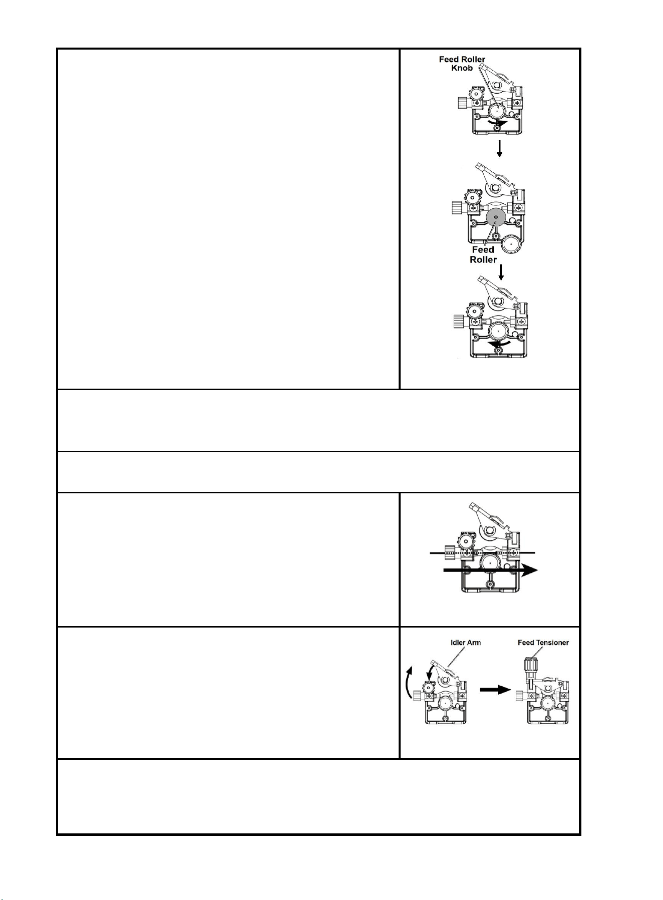
1.Release Feed Tensioner and rotate the Idler Arm away from
the Feed Roller.
NOTICE:
*Feed Tensioner knob could be turn counterclockwise to
loosen it. Then, pull it down to remove tension. The
spring-loaded Idler Arm will move upwards as illustrated.
Figure 14
Figure 13
13
2.Feed roller instructions.
Ensure that the visible, stenciled size on the drive roll side facing
you matches the wire size being used.
NOTICE:
Please pay attention to the model of the Feed Roller
Unscrew the Feed Roller Knob counterclockwise.
Remove the Feed Roller Knob to access the Feed Roller.
Flip or replace the Feed Roller as necessary. Ensure it
matches the wire type and diameter indicated on the Spool.
Figure 15
3.Carefully detach the end of the wire from the spool. Maintain tension on the wire to prevent the
spool from unwinding.
NOTICE: DO NOT release the wire
4.Trim all bent and crimped wire. Ensure the cut end is smooth without any burrs or sharp edges;
re-cut if necessary.
5.Keep tension on the wire and guide at least 12 inches of wire
through the Wire Inlet Liner, over the Feed Roller, and into the
gun liner.
NOTICE: The spool will rotate in a counter-clockwise
fashion.
Figure 16
6.Close the Idler Arm and turn down the Feed Tensioner until
the idle roller presses down firmly on the wire.
Now you may release the welding wire. Make sure the wire is
positioned in the groove of the lower feed roller.
Figure 17
7.The Feed Tensioner on the Idler Arm adjusts the pressure on the wire .Adjust pressure by
turning the Feed Tensioner to prevent spool overrun, but still allow smooth and easy wire feeding.
Start with the pressure set to an intermediate value. Readjust, if necessary. If the drive roll slips
while feeding wire, the pressure should be increased until the wire feeds properly.
14
5. OPERATION FOR MIG AND
FLUX CORED WELDING
! WARINING DO NOT set up without SWITCH OFF!
5.1 Connection For Flux Cored Welding
Description
Picture
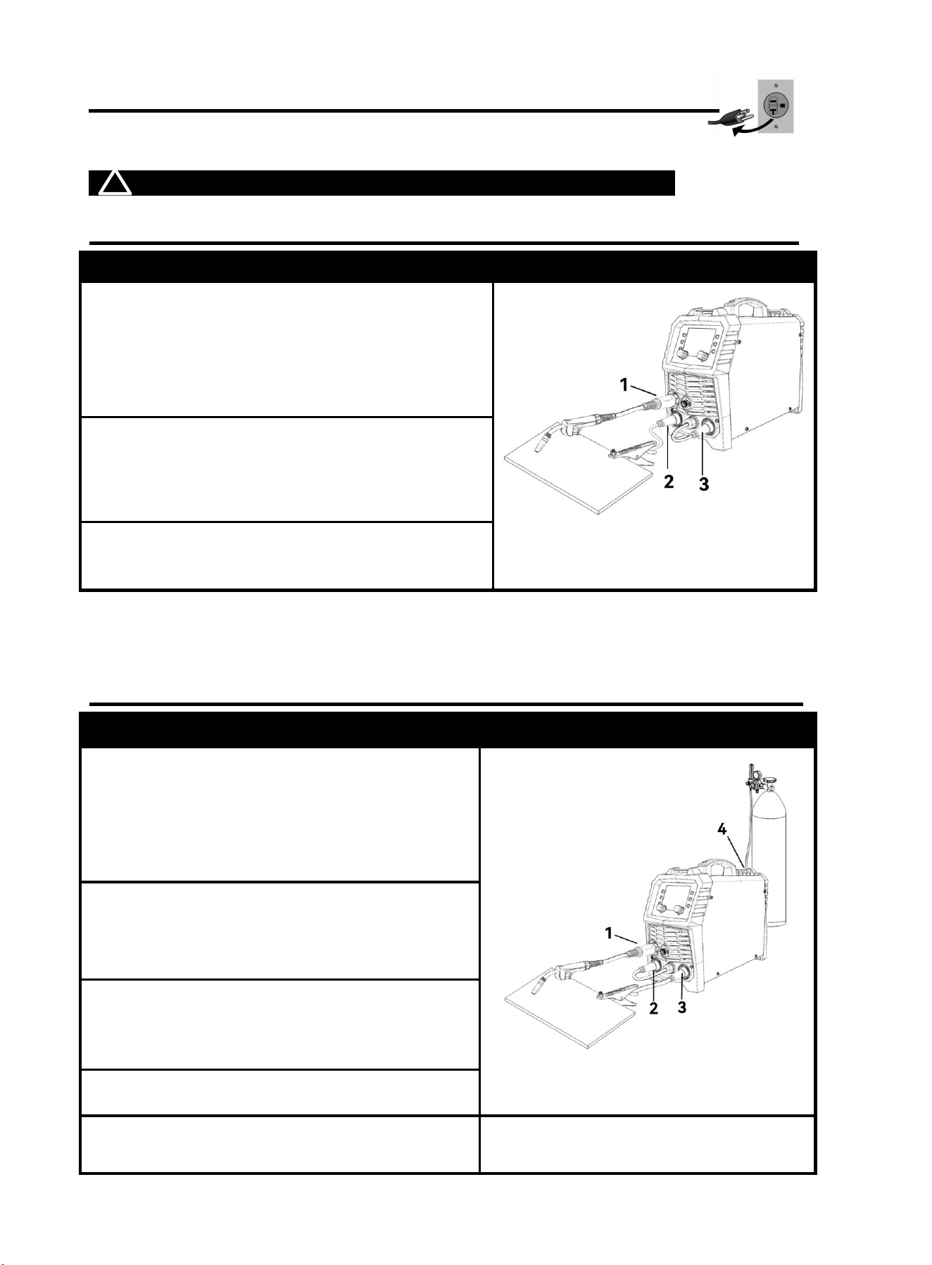
1. Connect the welding gun to euro connector
NOTICE:
The connector MUST be tightly connected to the
socket to avoid power short circuit or air leakage.
Figure 18
2.Connect the ground clamp to “+” Positive Output.
NOTICE:
Ensure the ground clamp is connected on
clean, bare metal (not rusty or painted).
3.Connect the polarity changeover plug to “-”
Negative Output.
5.2 Connection For MIG/MAG Welding
Description
Picture
1. Connect the welding gun to euro connector
NOTICE:
The connector MUST be tightly connected to the
socket to avoid power short circuit or air
leakage.
Figure 19
2. Connect the polarity changeover plug to “+”
Positive Output.
3.Connect the ground clamp to “-” Positive Output.
NOTICE:
Ensure the ground clamp is connected on
clean, bare metal (not rusty or painted).
4. Connect the gas hose to the regulator and the
GAS IN .
1. With assistance, place an 100% CO2 cylinder
(not included) onto a cabinet or cart near the Welder
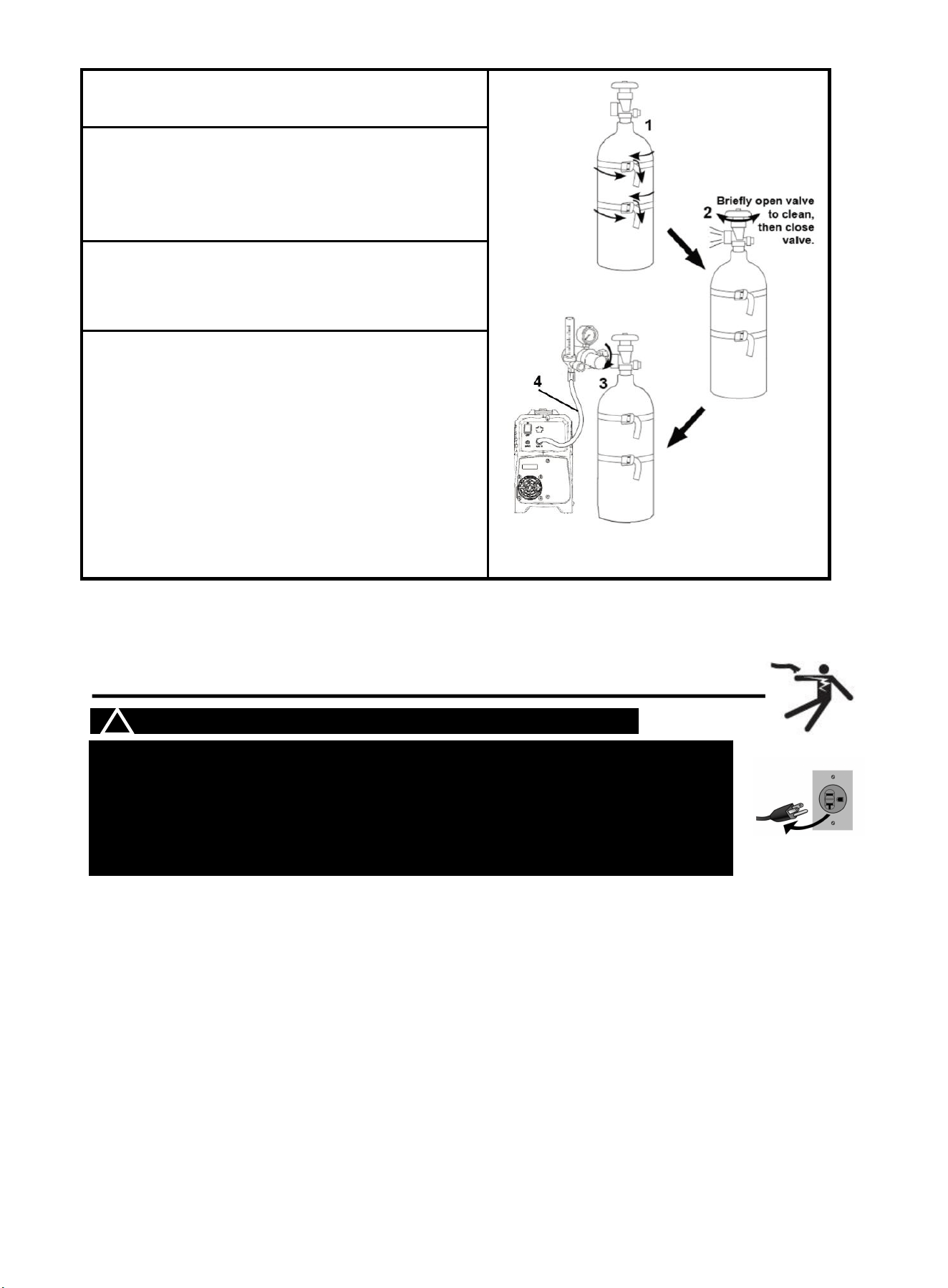
15
and secure the cylinder in place with two straps (not
included) to prevent tipping.
2. Remove the cylinder’s cap. Stand to the side of
the valve opening, then open the valve briefly to blow
dust and dirt from the valve opening. Close the
cylinder valve.
3. Locate the Regulator(Not Included) and close its
valve until it is loose, then thread Regulator onto
cylinder and wrench-tighten connection.
4. Connector the gas hose to the Regulator’s Outlet
and the welder’s Gas inlet connector.
NOTICE:
The gas hose connector MUST be tightly
connected to the socket to avoid air leakage.
5.3 Input Power Connection
! WARINING BEWARE OF ELECTRIC SHOCK!
NOTICE: The following steps require applying power to the Welder with the
cover open.
To prevent serious injury from fire or electric shock:
1.DO NOT touch anything, especially not the ground clamp, with the gun or
welding wire or an arc will be ignited.
2. DO NOT touch internal Welder Components while it is plugged in.
The MIG200P operates with a 110V or 220V power supply. Plug the Power Cord into a
properly grounded. Set MIG Gun down on nonconductive, nonflammable surface away
from any grounded objects. And then turn the Power Switch ON.
NOTE:
For optimal performance, connect the MIG200P to a 50A branch circuit. If connected to a circuit with
lower capacity, expect reduced welding current and duty cycle. The circuit must be equipped over
50A with delayed action-type circuit breaker or fuses.
Ensure the mains supply voltage remains within ±15% of the rated value (110V/220V). Low voltage
can lead to subpar welding results, while excessively high voltage may cause components to
overheat and potentially fail. Check whether the voltage value varies in acceptable range with a
multi-meter.
Code Requirements for Electrical Input Connections
This welding machine must be connected to a power source in accordance with applicable electrical
codes. The National Electrical Code provides standards for amperage handling capability of supply
Figure 20
16
conductors based on duty cycle of the welding source.
NOTICE: Do not remove the power cord ground prong.
If there is any other question about the installation meeting applicable electrical code requirements,
consult a qualified electrician.
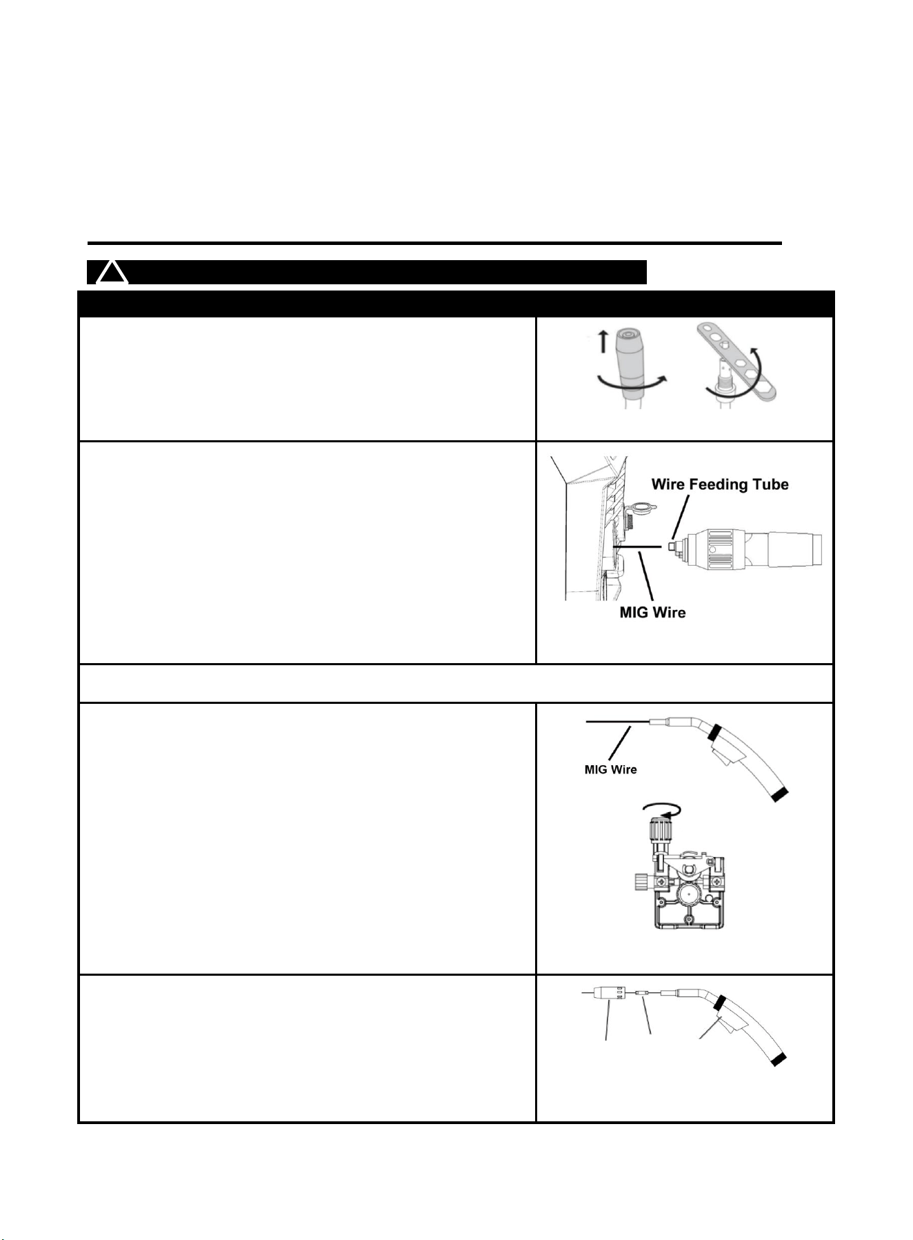
5.4 Wire Stick Out
! WARINING BEWARE OF ELECTRIC SHOCK!
Description
Picture
1.Rotate counterclockwise to remove the nozzle.
2.Rotate counterclockwise to remove the contact tip.
Note:Checking the size number on the contact tip. If not
confirmed with your welding wire, change it.
3.Thread the welding wire through the wire feeding tube on
the Mig torch interface, and then install and tighten the
welding torch connector.
Note: If the front end of the welding wire is curled, it needs to
be
trimmed flat
4.Turn on the welding machine power supply, Set the Mode Switch to MIG setting.
5. Press and hold the gun trigger to load the wire through
the gun, until the wire
feeds through the end of the Gun of 1.5-2.5inch long.
NOTE:
If the wire stops instead of bending, disconnect the
Welder, tighten the Feed
Tensioner slightly clockwise, and try again. If the wire
bends due to feed
pressure, the tension is set correctly. Point the Gun
away from all objects.
6. Replace the nozzle and Contact Tip in counterclockwise,
Subtract the excess mig welding wire and retain 0.4-0.6
inches
of wire to expose the noise,The machine is now ready to weld.
Figure 22
Figure 24
Nozzl
Contact
Tip
MIG
Gun
Figure 21
Figure 23
17
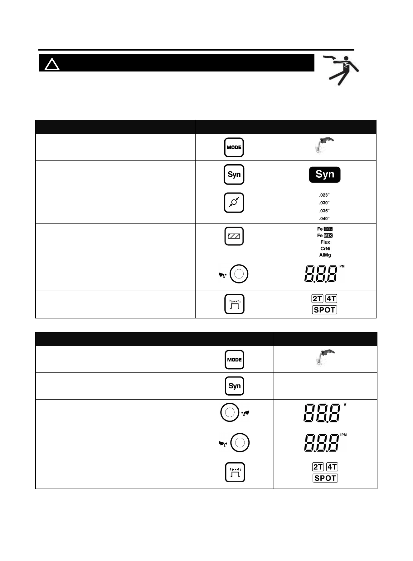
5.5 Operation
! WARINING BEWARE OF ELECTRIC SHOCK!
Turn on the power switch of the machine, and the power indicator illuminates.
Select proper working mode and proper function according your welding situation.
Clamp the Ground clamp onto the workpiece, The Ground clamp must be securely connected to the
workpiece.
Function with synergic
Part
Select
Select MIG
Open SYN
Select wire
diameter
Select MIG material according to the workpiece
and inlet gas. If using flux cored wire, please
choose FLUX.
Turn the knob to find the required current or
IPM
Select 2T / 4T / Spot
Function with separated
Part
Select
Select MIG
Close SYN
/
Turn the knob to find the required voltage
Turn the knob to find the required IPM
Select 2T / 4T / Spot
Clamp the Ground clamp onto the workpiece, The Ground clamp must be securely connected to
the workpiece.
NOTICE:
18
•
Always weld clean, dry and well-prepared material.
•
Hold gun at a 45° angle to the workpiece with nozzle about 12mm from the surface.
• Move the gun smoothly and steadily as you weld.
•
On thin gauge material, move quickly and only weld 6mm stitch-welds at a time to avoid
melt-through.
• Avoid welding in very drafty areas. A weak, pitted and porous weld will result due to drafts
blowing away the Shielding gas.
•
Keep wire and liner clean. Do not use rusty wire.
• Sharp bends or kinks in the welding cable should be avoided.
6. Operation for Spool gun(Not Included)
! WARINING DO NOT set up without SWITCH OFF !
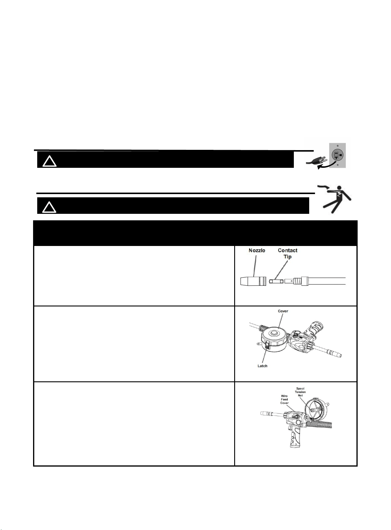
6.1 Set Up Spool gun
! WARINING BEWARE OF EL ECTRIC SHOCK!
Description
Picture
Clockwise pull the nozzle to remove it. Unscrew the Contact
Tip counterclockwise and remove it.
Open Latch and remove Cover.
note:
To prevent unraveling, leave wire secured to Spool.
Loosen Spool Tension Nut.
Install Spool so wire will feed clockwise.
Tighten Spool Tension Nut until Spool cannot spin freely.
Figure 27
Figure 25
Figure 26
19
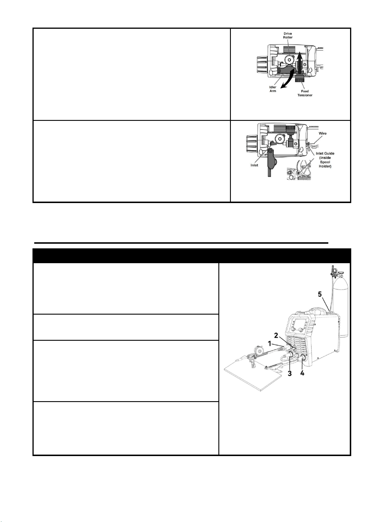
Open Wire Feed Cover.
Pull up on Feed Tensioner, then swing up and over to expose
Idler Arm.
Open Idler Arm to expose wire feed components.
Remove Drive Roller knob. Make sure number on Drive Roller
matches wire diameter. Flip Drive Roller if necessary.
Figure 28
Hold end of wire while releasing from Spool. Cut off any bent
wire.
Keeping tension on Spool, feed Wire through Inlet Guide and
1/4" into Inlet .
Close Idler Arm and Feed Tensioner.
Replace Spool Cover.
Set Spool Gun down on nonconductive, nonflammable
surface away from any grounded objects.
Figure 29
6.2 Connection
Description
Picture
1. Connect the spool gun to euro connector
NOTICE:
The spool gun connector MUST be tightly connected to
the socket to avoid power short circuit or air leakage
2. Connect the spool gun control line to socket and tighten
it.
3. Connect the polarity changeover plug to “+” Positive
polarity
NOTICE:
DCEN or DCEP should be selected according to the
specific welding material.
4. Connect the ground clamp to “-” negative polarity
NOTICE:
DCEN or DCEP should be selected according to the
specific welding material.
Figure 30
20
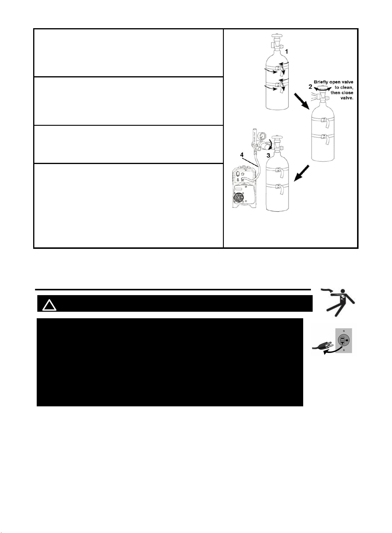
1. With assistance, place an 100% argon cylinder (not
included) onto a cabinet or cart near the Welder and secure
the cylinder in place with two straps (not included) to
prevent tipping.
2. Remove the cylinder’s cap. Stand to the side of the
valve opening, then open the valve briefly to blow dust and
dirt from the valve opening. Close the cylinder valve.
3.
Locate the Regulator and close its valve until it is loose,
then thread Regulator(Not Included) onto cylinder and
wrench-tighten connection.
4. Connector the gas hose to the Regulator’s Outlet and the
welder’s Gas inlet connector.
NOTICE:
The gas hose connector MUST be tightly connected to the
socket to avoid air leakage.
6.3 Input Power Connection
! WARINING BEWARE OF ELECTRIC SHOCK!
NOTICE: The following steps require applying power to the Welder
with the cover open.
To prevent serious injury from fire or electric shock:
1.DO NOT touch anything, especially not the ground clamp, with the
gun or welding wire or an arc will be ignited.
2. DO NOT touch internal Welder Components while it is plugged in.
The MIG200P operates with a 110V or 220V power supply. Plug the Power Cord into a
properly grounded. Set MIG Gun down on nonconductive, nonflammable surface away
from any grounded objects. And then then turn the Power Switch ON.
NOTE
:
For optimal performance, connect the MIG200P to a 50A branch circuit. If connected to a circuit with
lower capacity, expect reduced welding current and duty cycle. The circuit must be equipped over
50A with delayed action-type circuit breaker or fuses.
Ensure the mains supply voltage remains within ±15% of the rated value (110V/220V). Low voltage
Figure 31
21
can lead to subpar welding results, while excessively high voltage may cause components to
overheat and potentially fail. Check whether the voltage value varies in acceptable range with a
multi-meter.
Code Requirements for Electrical Input Connections
This welding machine must be connected to a power source in accordance with applicable electrical
codes. The National Electrical Code provides standards for amperage handling capability of supply
conductors based on duty cycle of the welding source.
NOTICE: Do not remove the power cord ground prong.
If there is any other question about the installation meeting applicable electrical code requirements,
consult a qualified electrician.
6.4 Operation
! WARINING BEWARE OF ELECTRIC SHOCK!
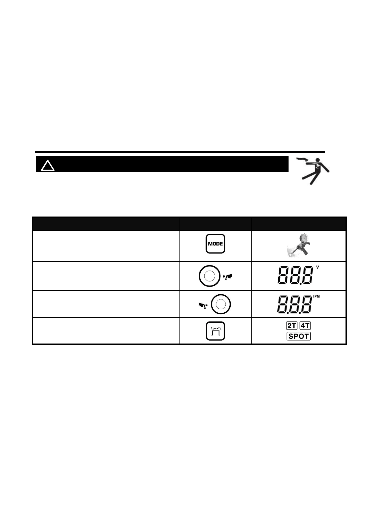
Turn on the power switch of the machine, and the power indicator illuminates.
Select proper working mode and proper function according your welding situation.
Clamp the Ground clamp onto the workpiece, The Ground clamp must be securely connected to the
workpiece.
Function with separated
Part
Select
Select MIG
Turn the knob to find the required voltage
Turn the knob to find the required IPM
Select 2T / 4T / Spot
NOTICE:
•
Always weld clean, dry and well-prepared material.
• Hold gun at a 45° angle to the workpiece with nozzle about 1/2” from the surface.
•
Move the gun smoothly and steadily as you weld.
• On thin gauge material, move quickly and only weld 1/4” stitch-welds at a time to
avoid melt-through.
•
Avoid welding in very drafty areas. A weak, pitted and porous weld will result due
to drafts blowing away the
• Keep wire and liner clean. Do not use rusty wire.
•
Sharp bends or kinks in the welding cable should be avoided
• ONLY use MIG solid welding wire.
22
7. Operation for MMA and TIG
! WARINING DO NOT set up without SWITCH OFF !
7.1 MMA Welder Cable Connection
NOTICE: Before setting up or using this product for new function, make
sure to read the entire Important Safety Information section at the beginning of this
manual!
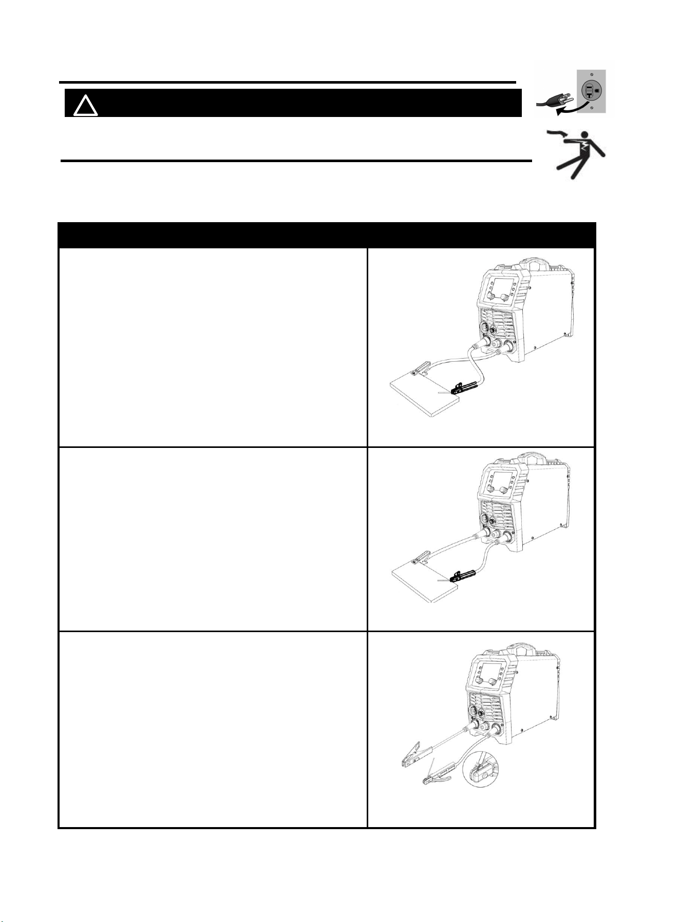
Description
Picture
DCEP:Alkaline rods (E7018)
1. Connect the ground clamp to “-” Negative polarity
2. Connect the Electrode Holder to “+” Positive
polarity
NOTE:
Ensure the ground clamp is connected on clean,
bare metal (not rusty or painted).
DCEN:Acidic rods (E6013)
1. Connect the ground clamp to “+” Negative polarity
2. Connect the Electrode Holder to “-” Positive
polarity
NOTE:
Ensure the ground clamp is connected on clean,
bare metal (not rusty or painted).
Place the bare metal end of the Stick Electrode (sold
separately) inside the jaws of the Electrode Holder.
NOTE: Set Electrode Holder down on
nonconductive, nonflammable surface away from
any grounded objects.Install Stick Electrode with
the machine turned off.
Figure 32 DCEP
Figure 33 DCEN
Figure 34
23
7.2 MMA Welder Operation
! WARINING BEWARE OF ELECTRIC SHOCK!
NOTICE: The following steps require applying power to the Welder
with the cover open.
To prevent serious injury from fire or electric shock:
1.DO NOT touch anything, especially not the ground clamp, with the
gun or welding wire or an arc will be ignited.
2. DO NOT touch internal Welder Components while it is plugged in.
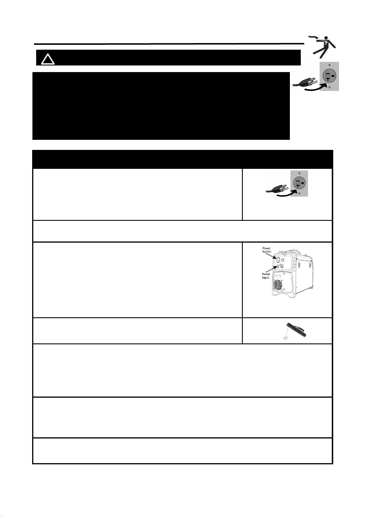
Operation steps
Picture
1.
connect power cord
NOTE:
Turn the Power Switch off before connecting Power Cord.
Plug the Power Cord into a properly grounded and rated receptacle
that matches the plug. The circuit must be equipped with delayed
action-type circuit breaker or fuses.
2. Place the bare metal end of the Stick Electrode (sold separately) inside the jaws of the Electrode
Holder.
3. Turn the Power Switch ON.
The Operation interface will light up and the Cooling fan will rotate.
NOTE:Welder is now energized and open circuit Voltage is
present.
4. Select MMA
5. Stroke the workpiece lightly to ignite the arc.
Tips for igniting the arc:
a. Tap the surface with the Electrode.
b. Stroke the surface with the Electrode.
c. Strike the surface like a match with the Electrode.
6. After the arc ignites:
a. Lift the Electrode off workpiece the same distance as the diameter of the bare metal end.
b. Tilt Electrode back 10 to 20 degrees.
c. Drag Electrode to the back end of the weld puddle to deposit material as needed.
7. The initial settings may need to be adjusted after stopping and carefully inspecting the weld.Proper
welding takes experience.
Figure 35
Figure 36
24
8. When finished welding; lift the Electrode from the workpiece, then set Electrode Holder down on
nonconductive, nonflammable surface away from any grounded objects.
9. Turn the Power Switch OFF
NOTE:
To prevent accidents, after use:
• Allow Welder to cool down.
• Unplug Welder’s power cord from outlet.
• Remove Ground Clamp.
• Disconnect Electrode Holder and Ground Cables.
10. Clean, then store Welder and its accessories indoors out of children’s reach.
7.3 Lift TIG Welder Cable Connection(Not Included)
! WARINING BEWARE OF ELECTRIC SHOCK!
NOTICE: The following steps require applying power to the Welder
with the cover open.
To prevent serious injury from fire or electric shock:
1.DO NOT touch anything, especially not the ground clamp, with the
gun or welding wire or an arc will be ignited.
2. DO NOT touch internal Welder Components while it is plugged in.
Description
Picture
1. Connect the ground clamp to “+” Positive polarity
NOTICE:
The ground clamp connecter MUST be tightly
connected to the socket to avoid power short
circuit.
Ensure the ground clamp is connected on clean,
bare metal (not rusty or painted).
Figure 37
25
Figure 39
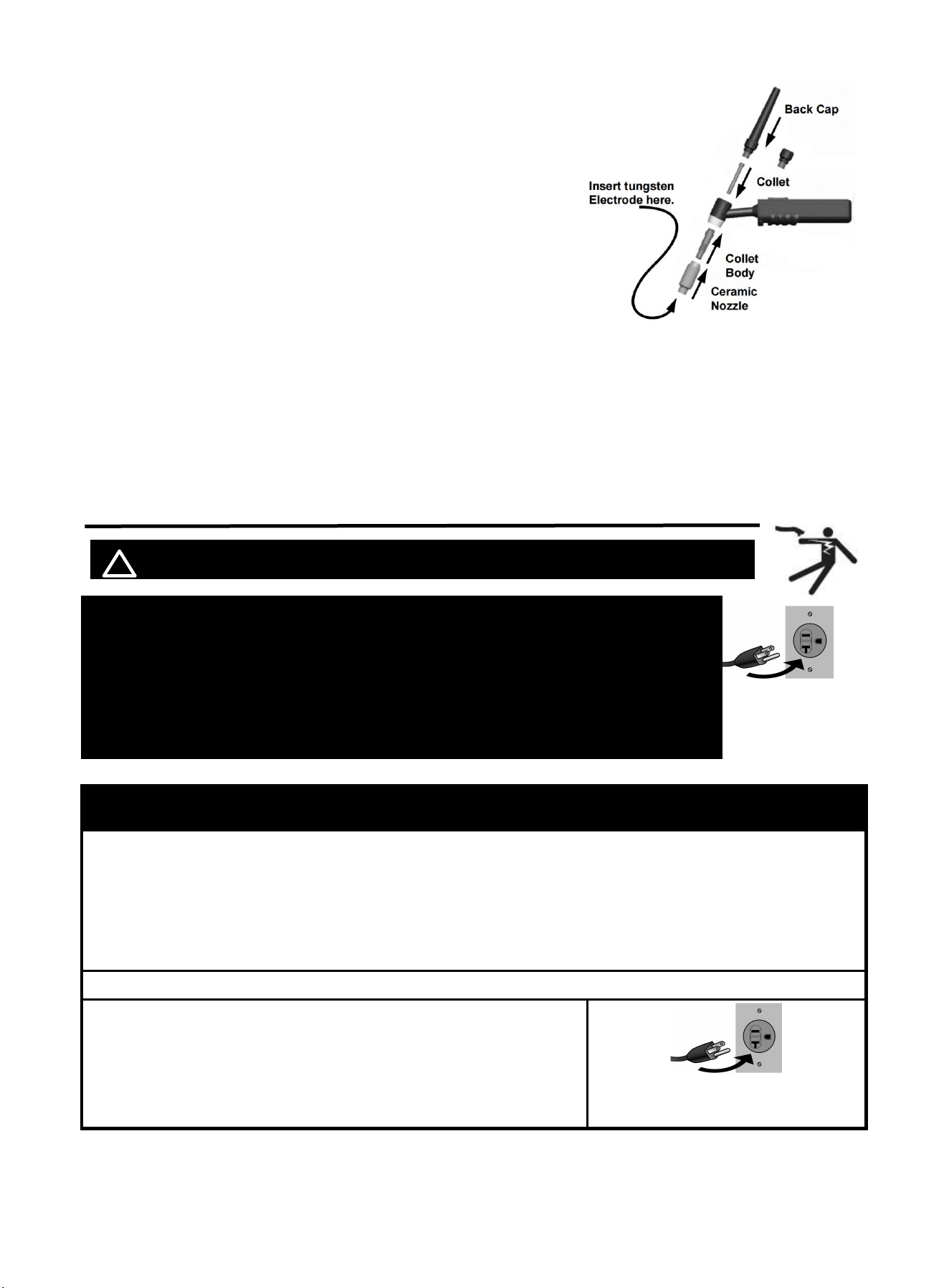
Sharpen tungsten Electrode
WARNING! TO PREVENT SERIOUS INJURY: Some Electrodes may contain materials that are
hazardous to breathe. Wear a respirator and ANSI-approved safety goggles when grinding an
Electrode.
To avoid Electrode contamination, dedicate a fine grit grinding wheel exclusively
to Electrode grinding.
1. Shut off the welder and wait until Electrode and Torch have cooled enough to
handle.
2. Remove Back Cap to release Collet’s grip on Electrode.
3. Pull Electrode out from front of Torch. (Pulling it from rear will damage Collet
and create burrs on Electrode).
4. If Electrode has dulled or been otherwise contaminated, use pliers or a suitable
tool to grip the Electrode above the contaminated section and snap off the end of
the Electrode.
5. Lightly press Electrode tip against the surface of the grinding wheel at an angle.
Rotate Electrode tip until a blunt point is formed.
NOTE: Grinding direction must be parallel to length of Electrode.
6. The conical portion of the ideal tip will be 2-1/2 times as long as the Electrode
diameter.
7. Re-insert Electrode into Collet with tip protruding 1/8"-1/4" beyond the Ceramic Nozzle, then re-tighten the
Back Cap to secure the Electrode in place.
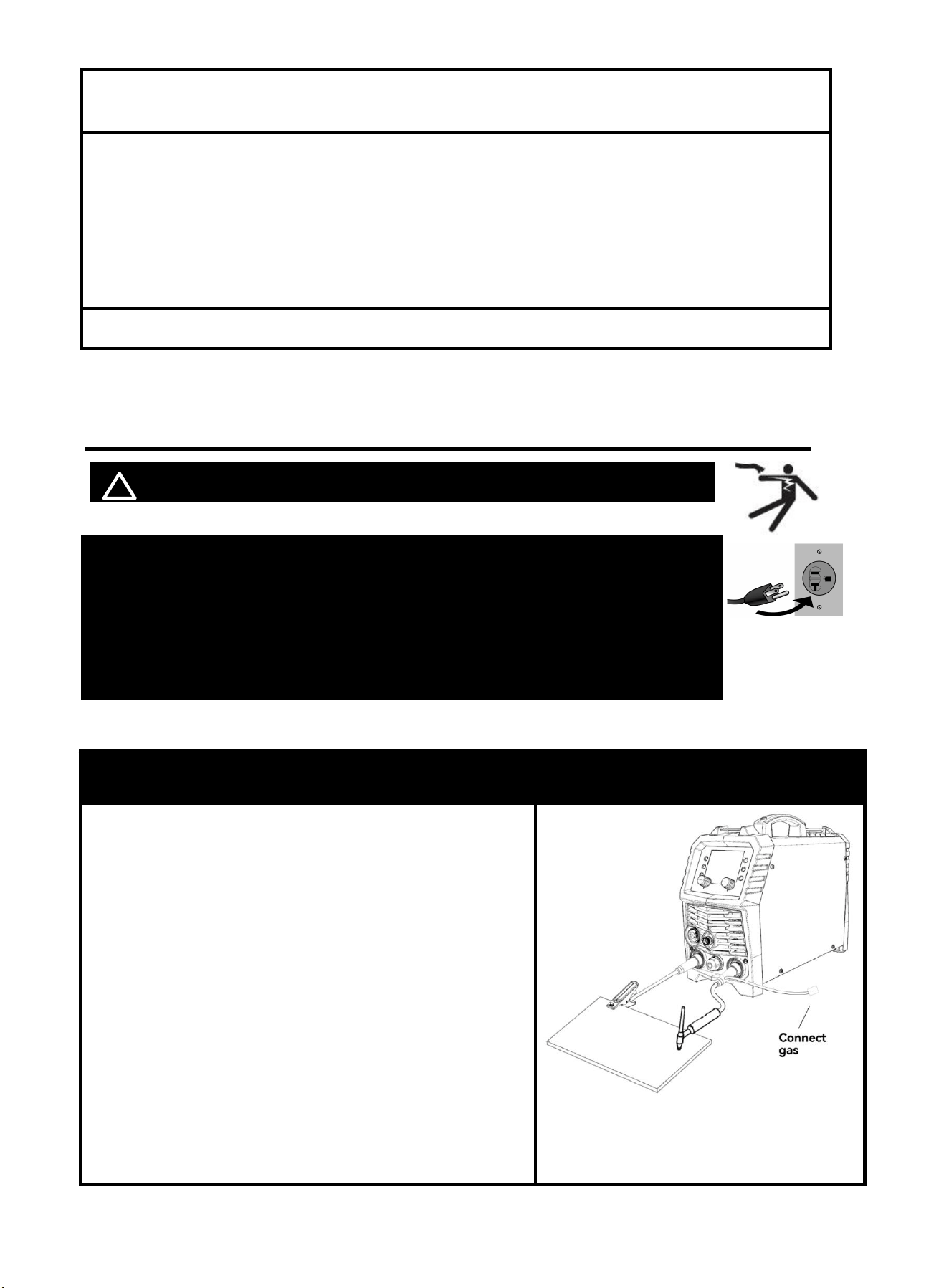
2. Connect the tig gun(Not Included) to “-” Negative
polarity
NOTICE:
The tig gun connecter MUST be tightly connected
to the socket to avoid power short circuit.
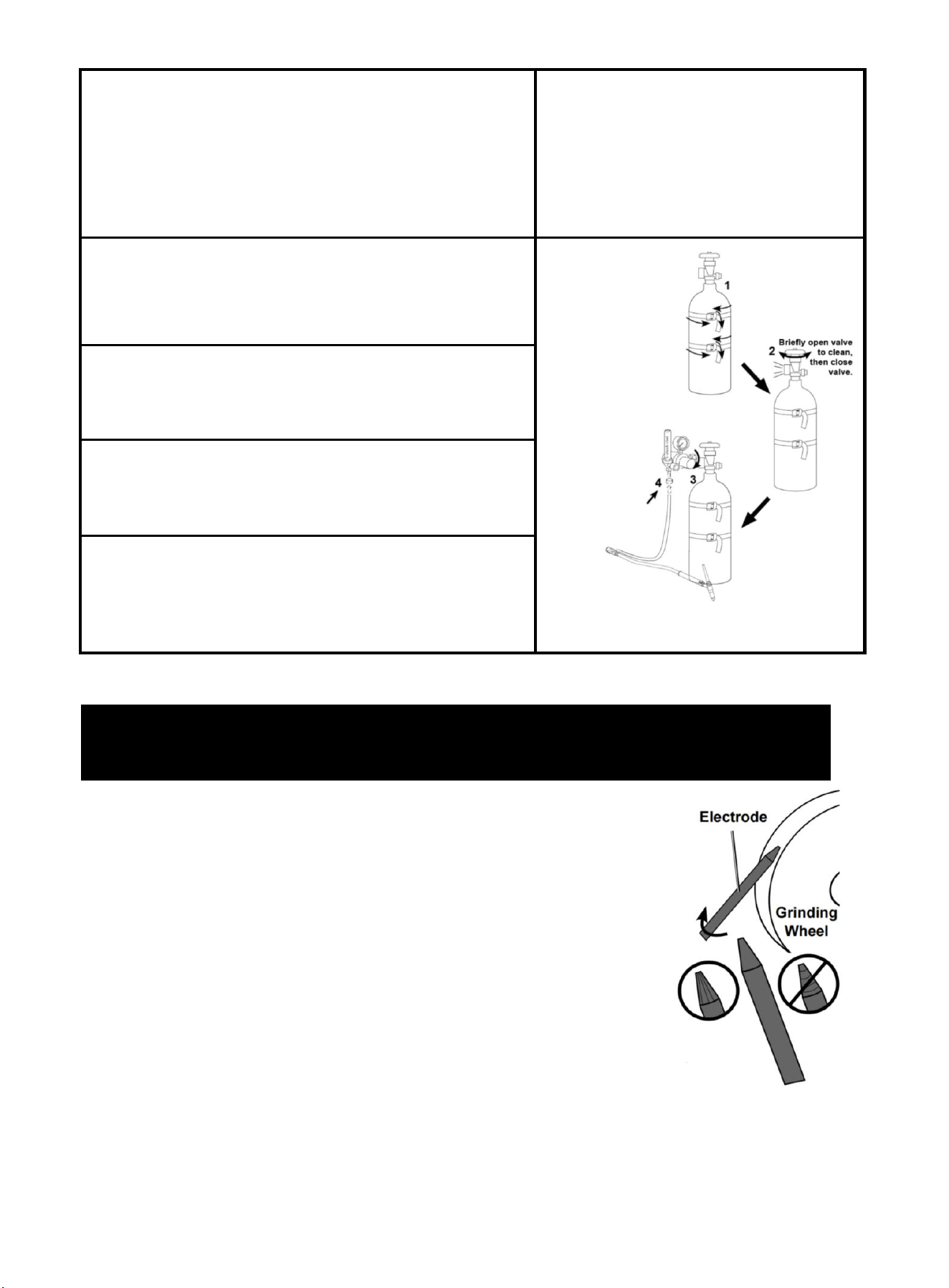
1. With assistance, place an 100% Argon cylinder (not
included) onto a cabinet or cart near the Welder and secure
the cylinder in place with two straps (not included) to prevent
tipping.
2.
Remove the cylinder’s cap. Stand to the side of the valve
opening, then open the valve briefly to blow dust and dirt from
the valve opening. Close the cylinder valve.
3.
Locate the Regulator (not included) and close its valve until
it is loose, then thread Regulator onto cylinder and
wrench-tighten connection.
4.
Connect Shielding Gas Hose on TIG Torch Cable
Connector to the Regulator’s Outlet and wrench-tighten
connection.
Figure 38
26
Figure 40
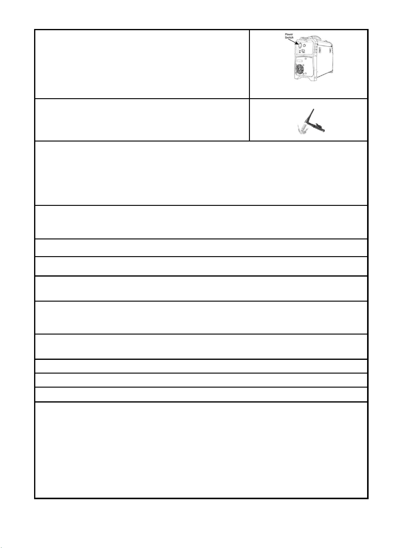
Assemble tig torch
1. Consult Settings Chart, on top of Welder, to determine proper
Tungsten Electrode size to be used with thickness of material to be
welded.
2. Match Collet and Collet Body sizes to Tungsten Electrode size.
3. Thread Collet Body into the front of the Torch.
4. Make sure Ceramic Nozzle size is appropriate for application.
5. Thread Ceramic Nozzle onto Collet Body.
6. Insert Collet into back of Torch and into Collet Body.
7. Insert Tungsten Electrode into Collet on front of Torch.
8. Lock Electrode in place with Back Cap. Electrode should protrude
1/8" to 1/4" beyond the Ceramic Nozzle.
NOTE: The tig torch and tungsten electrode are not included in the machine. If you need to
purchase, please log in to the official website: WWW.ARCCAPTAIN.COM
7.4 Lift tig Welder Operation
! WARINING BEWARE OF ELECTRIC SHOCK!
NOTICE: The following steps require applying power to the Welder
with the cover open.
To prevent serious injury from fire or electric shock:
1.DO NOT touch anything, especially not the ground clamp, with the
gun or welding wire or an arc will be ignited.
2. DO NOT touch internal Welder Components while it is plugged in.
Operation steps
1. Open gas cylinder’s valve all the way.
NOTE: TO PREVENT DEATH FROM ASPHYXIATION:
Do not open gas without proper ventilation. Fix gas leaks immediately. Shielding gas can displace
air and cause rapid loss of consciousness and death. Shielding gas without carbon dioxide can be
even more hazardous because asphyxiation can start without feeling shortness of breath.
2. Set Flow Gauge to SCFH value
3.
connect power cord
NOTE: Turn the Power Switch off before connecting Power
Cord. Plug the Power Cord into a properly grounded and rated
receptacle that matches the plug. The circuit must be equipped
with delayed action-type circuit breaker or fuses.
Figure 41
27
4. Turn the Power Switch ON.
NOTE: Set TIG Torch down on nonconductive, nonflammable
surface away from any grounded objects.
The Operation interface will light up and the Cooling fan will rotate.
5. Select Lift TIG
NOTE:
Welder is now energized and open circuit Voltage is
present.
6. Hold TIG Torch in one hand and the TIG Rod (sold separately) in other hand. Both hands need to wear
protective gloves.
WARNING! TO PREVENT SERIOUS INJURY: Metalwork bench must be grounded when TIG
welding.
NOTE: Maintain a constant distance between the Tungsten Electrode and the workpiece: between
1 and 1.5 times the diameter of the Electrode.
7. The initial settings may need to be adjusted after stopping and carefully inspecting the weld. Please refer
to 6.7 Lift TIG Welding parameters table,Proper welding takes experience.
8. Open valve on TIG Torch to start gas flow.
9. To initiate welding arc, touch Electrode to work piece and lift.
10. When welding puddle is hot enough, tilt Torch backward about 10-15 degrees from vertical and
move it back slightly. Add TIG Rod material as needed to the front end of the weld puddle.
11. Alternate between pushing the torch/weld puddle and adding the TIG Rod material.
NOTE: Remove the TIG Rod each time the Electrode is advanced, but do not remove it from the gas shield.
This prevents oxidation from contaminating the weld.
12. When finished welding, pull Torch away from work piece until welding arc is broken, then return the gas
coverage until weld solidifies.
13. Close valve on TIG Torch and turn Right Knob to OFF to turn off power to TIG Torch.
14. Set TIG Torch down on nonconductive, nonflammable surface away from any grounded objects.
15. Turn the Power Switch OFF.
16. To prevent accidents, after use:
• Allow Welder to cool down.
• Unplug Welder’s power cord from outlet.
• Remove Ground Clamp from workpiece or table.
• Disconnect TIG Torch and Ground Cables.
• Close gas cylinder’s valve securely, remove regulator and replace cap.
• Disconnect Gas Hose from Welder.
• Store and secure gas cylinder.
• Clean, then store Welder and its accessories indoors out of children’s reach.
Figure 42
28
8. Engineer Mode
! WARINING BEWARE OF ELECTRIC SHOCK!
8.1 Setting of system parameters
A default set of common welding parameters for this machine can be revised by revising system
parameters in case of need. Below is method:
NOTE:
The default parameters of the welder are modified for experienced welders.
The default parameters of the welder have been set in the best state. Do not change the
default parameters of the welder unless necessary.
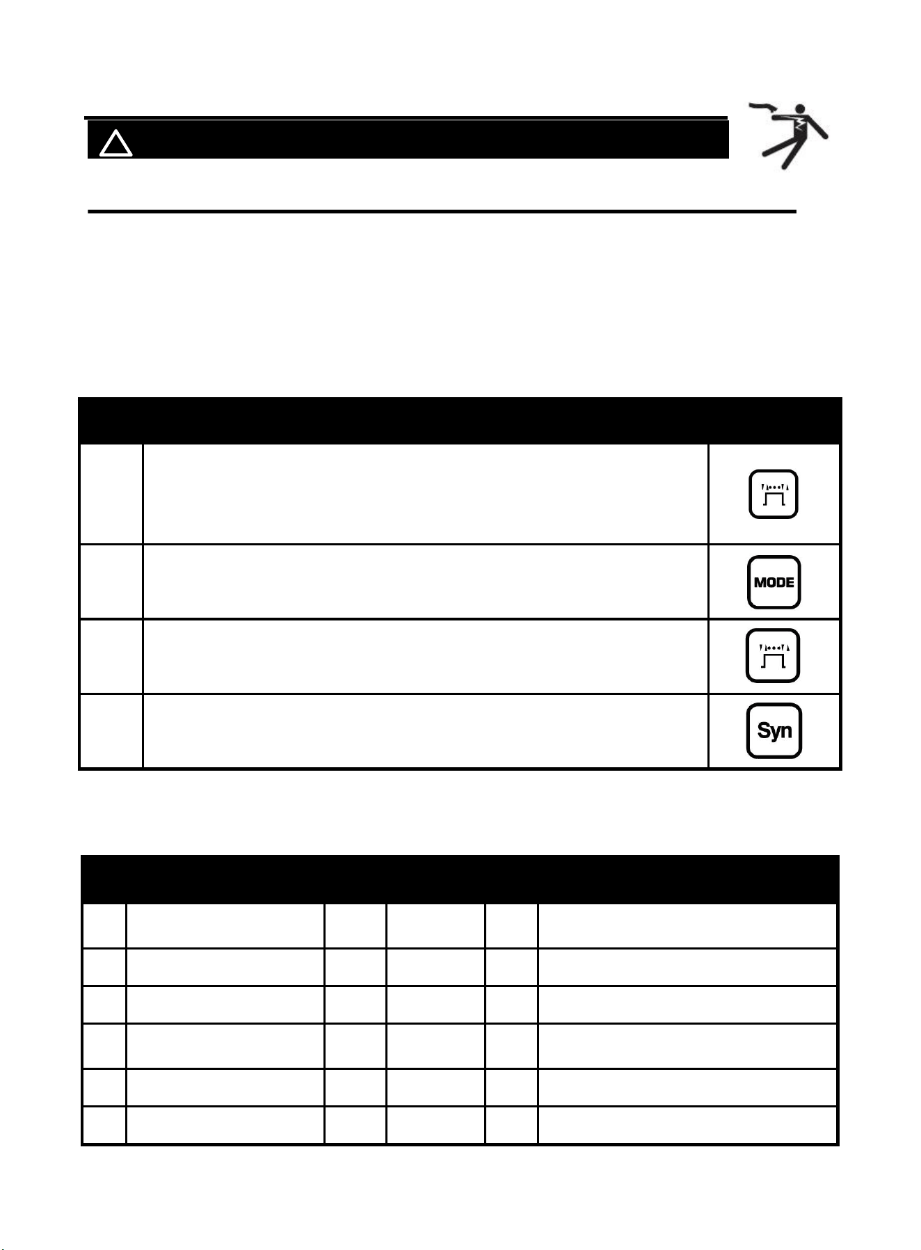
NO
operation
Picture
1
Press MIG operation mode selection button without releasing, turn on the
power switch of the welder. As soon as display shows “db9”, release MIG
operation mode selection button to enter revision interface of system
parameters.
2
Select system parameters of MIG, TIG or MMA by pressing Welding
process selection button.
3
Select the parameter to be revised by The knob on the left. Revise the
parameter value by The knob on the right. After revision, press MIG
operation mode selection button to save.
4
After revising parameters, press Synergic button again to exit the setting of
system parameters to be in normal standby.
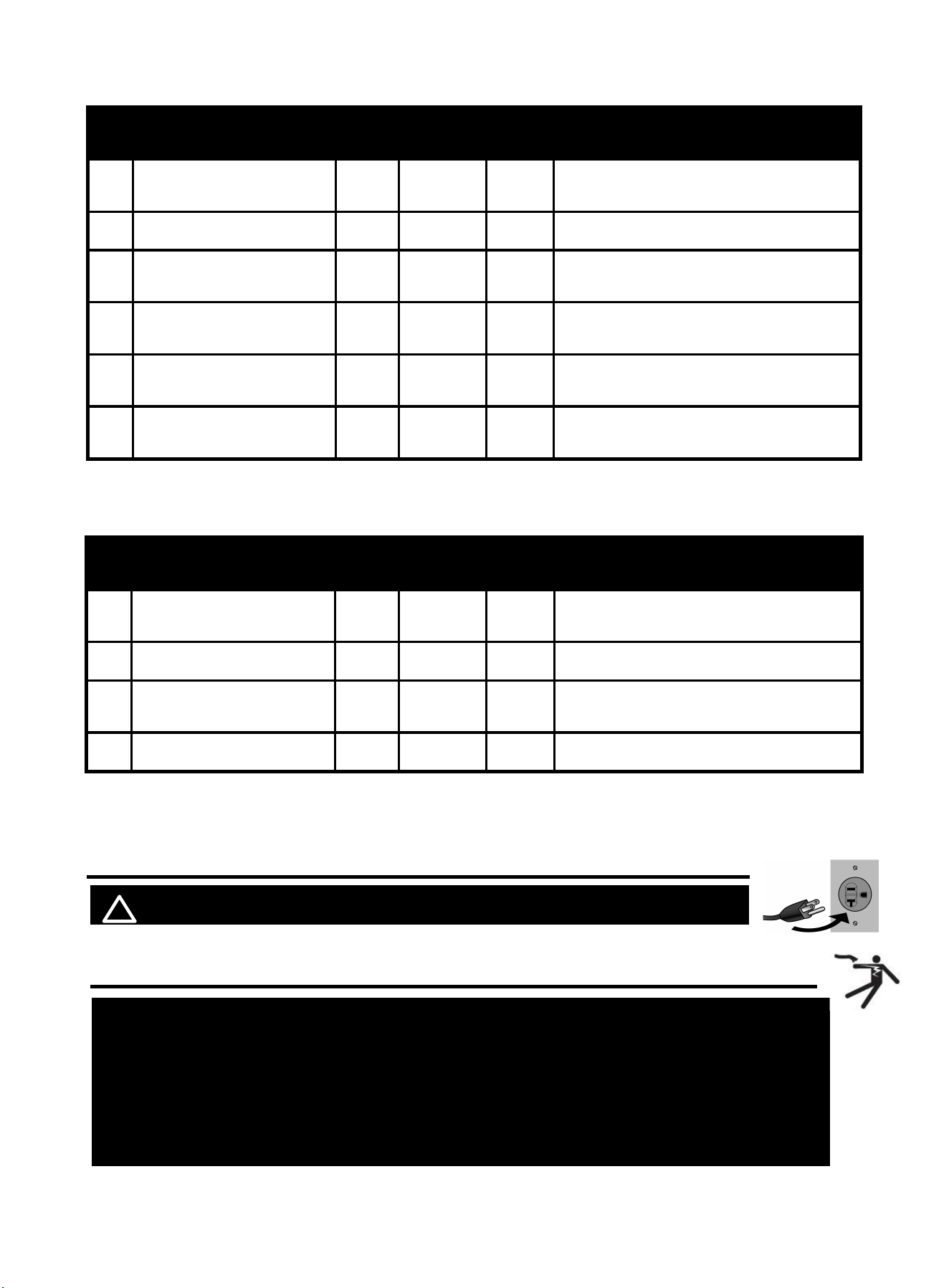
System parameter:
MIG mode
No.
Function parameter
Default
Setting
range
Unit
Description
P01
Background parameters
initialization
off
on/off
-
Restore factory default
(Select “on” to restore factory default)
P02
Welding time calculation
0
/
-
Not enabled
P03
Burn-back time at MIG
0.20
0.15
~
0.50
S
Burn-back time at MIG
P04
Burn-back voltage at MIG
12.0
10.0~18.0
V
Given output voltage of removing metal
ball after releasing torch trigger at MIG
P05
Pre-flow time at MIG
0.05
0.01
~
0.30
S
Pre-flow time at MIG
P06
Post-flow time at MIG
0.5
0.1
~
5.0
S
Post-flow time at MIG
29
MMA mode
No.
Function parameters
Default
Setting
range
Unit
Description
P01
Background parameters
initialization
off
on/off
-
Restore factory default
(Select “on” to restore factory default)
P02
Welding time calculation
0
/
/
Not enabled
P03
VRD switch at MMA
off
on/off
-
VRD switch at MMA
(“off”: VRD is off, “on”:VRD is on)
P04
Arc-force current at MMA
50
0
~
80
A
Given current value when output voltage
is below 14V at MMA
P05
Arc ignition current at MMA
60
0~100
A
Given current value of arc ignition at
MMA
P06
Arc ignition time at MMA
400
300
~
999
ms
Duration for given current value of arc
ignition at MMA(400 represents 400ms)
TIG mode
No.
Function parameters
Default
Setting
range
Unit
Description
P01
Background parameters
initialization
off
On/off
-
Restore factory default
(Select “on” to restore factory default)
P02
Welding time calculation
0
/
/
Not enabled
P03
Lift TIG current
50
35
~
65
A
Current value when tungsten and
workpiece are shorted at Lift TIG
P04
Post-flow time at TIG
/
/
/
Not enabled
9. MIG Basic Welding Technique
! WARINING BEWARE OF ELECTRIC SHOCK!
9.1 Basic MIG Welding
Good weld quality and profile depend on factors like gun angle, travel direction, electrode extension
NOTICE: The following steps require applying power to the Welder with the
cover open.
To prevent serious injury from fire or electric shock:
1.DO NOT touch anything, especially not the ground clamp, with the gun or
welding wire or an arc will be ignited.
2. DO NOT touch internal Welder Components while it is plugged in.
30
(stick out), feeding speed, base metal thickness, wire feed speed (amperage), and arc voltage. Here are
some basic guidelines to help with your setup:
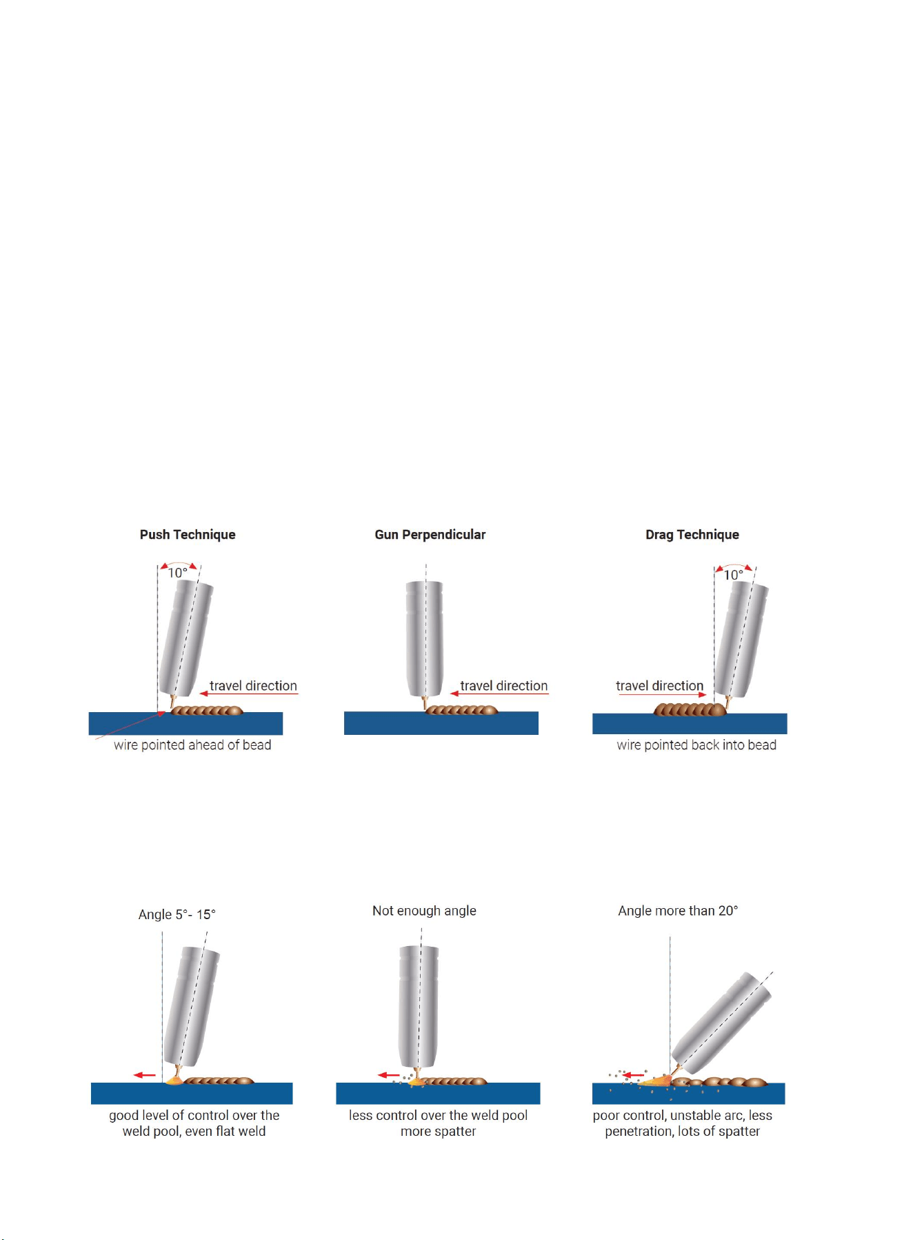
Gun Position and Travel Direction
Gun position refers to how the wire is directed at the base metal, including the angle and travel direction
chosen. Feeding speed and work angle affect the weld bead profile and penetration depth.
Push Technique
In the push technique, the wire is positioned at the leading edge of the weld pool and pushed towards
the unmelted work surface. This technique offers a clear view of the weld joint and wire direction. It
directs heat away from the weld puddle, allowing for faster feeding speeds, resulting in a flatter weld
profile with light penetration. It's suitable for welding thin materials, producing wider and flatter welds with
minimal cleanup or grinding required.
Perpendicular Technique
In the perpendicular technique, the wire is fed directly into the weld. This method is primarily used in
automated situations or when necessary. It typically results in a higher weld profile and deeper
penetration.
Drag Technique
With the drag technique, the gun and wire are pulled away from the weld bead. The arc and heat focus
on the weld pool, resulting in more heat on the base metal, deeper melting, increased penetration, and a
higher weld profile with more buildup.
Travel Angel
Travel angle is the right to left angle relative to the direction of welding. A travel angle of 5°- 15° is ideal
and produces a good level of control over the weld pool. A travel angle greater that 20° will give an
unstable arc condition with poor weld metal transfer, less penetration, high levels of spatter, poor gas
shield and poor quality finished weld.
Figure 43
Figure 44
31
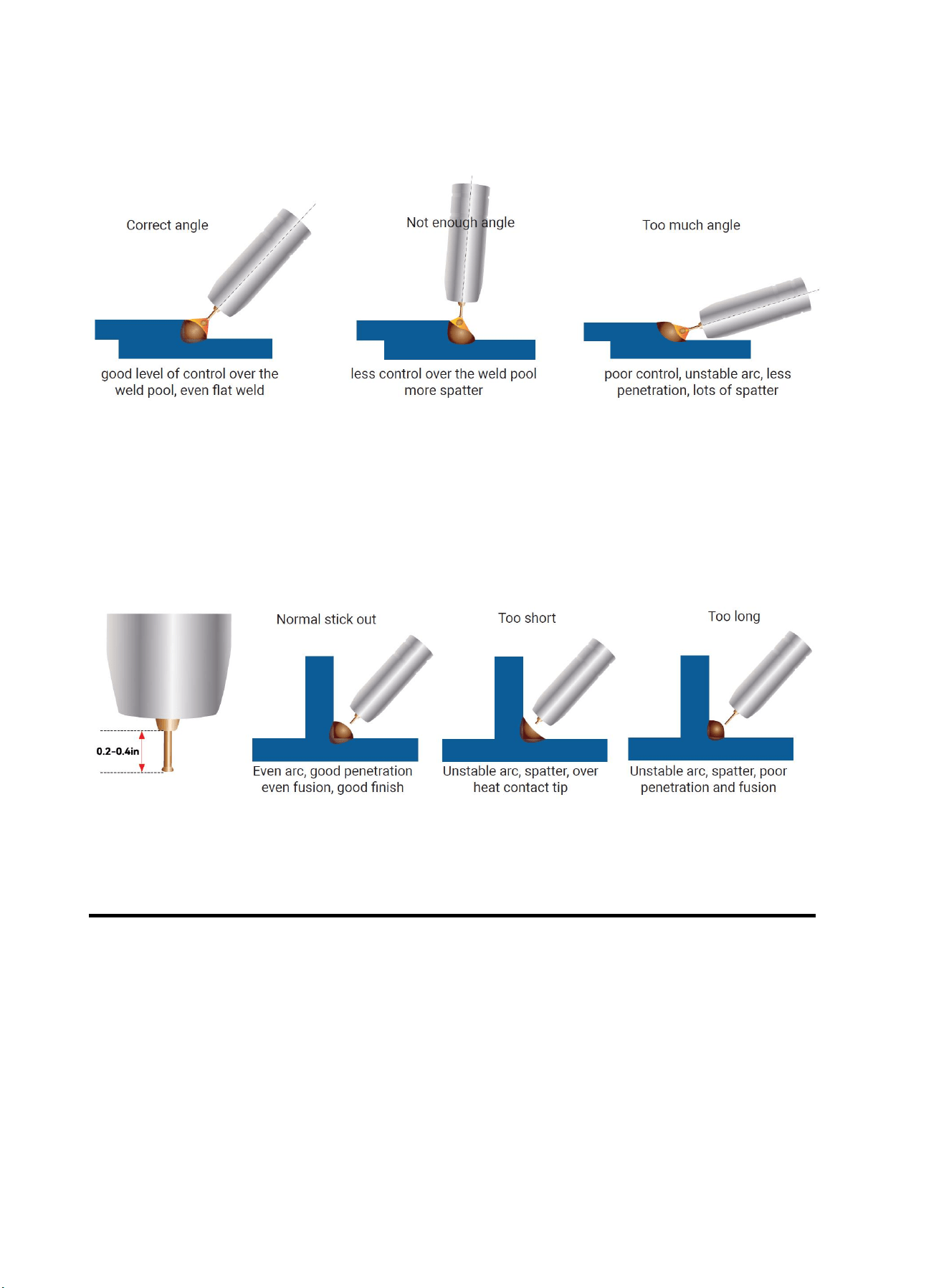
Angle to Work
The work angle is the forward back angle of the gun relative to the work piece.The correct work angle
provides good bead shape, prevents undercut, uneven penetration, poor gas shield and poor quality
finished weld.
Stick Out
Stick out is the length of the unmelted wire protruding from the end of the contact tip. A constant even
stick out of 0.2-0.4in will produce a stable arc, and an even current flow providing good penetration and
even fusion. Too short stick out will cause an unstable weld pool, produce spatter and over heat the
contact tip. Too long stick out will cause an unstable arc, lack of penetration, lack of fusion and increase
spatter.
9.2 Feeding Speed
Feeding speed refers to how quickly the gun is moved along the weld joint, measured in inches per
minute. It can vary based on conditions and the welder's skill, limited by their ability to control the weld
pool. The push technique allows for faster feeding speeds compared to the drag technique. Gas flow
should match the feeding speed, increasing with faster feeding and decreasing with slower speed.
Feeding speed should match the amperage and decreases as material thickness and amperage
increase.
Too Fast Feeding Speed
Too fast feeding speed results in insufficient heat per inch of travel, leading to less penetration and
reduced weld fusion. The weld bead solidifies quickly, trapping gases inside and causing porosity.
Undercutting of the base metal may occur, leaving an unfilled groove in the base metal.
Too Slow Feeding Speed
Figure 45
Figure 46
32
Too slow feeding speed produces a wide weld with inadequate penetration and fusion. The arc energy
remains on top of the weld pool, resulting in excessive weld metal deposition per inch and poor-quality
weld deposits.
Correct Feeding Speed
The correct feeding speed maintains the arc at the leading edge of the weld pool, allowing sufficient
melting of the base metal for good penetration, fusion, and wetting out of the weld pool. This produces a
high-quality weld deposit.
10. MAINTENANCE
! WARINING BEWARE OF ELECTRIC SHOCK!
NOTICE: To prevent serious injury, fire, and burns:
Unplug the welder.
Place the MIG gun on a heat-proof, electrically non-conductive
surface.
Allow all parts of the welder to cool completely before servicing.
10.1 Routine and Periodic Maintenance
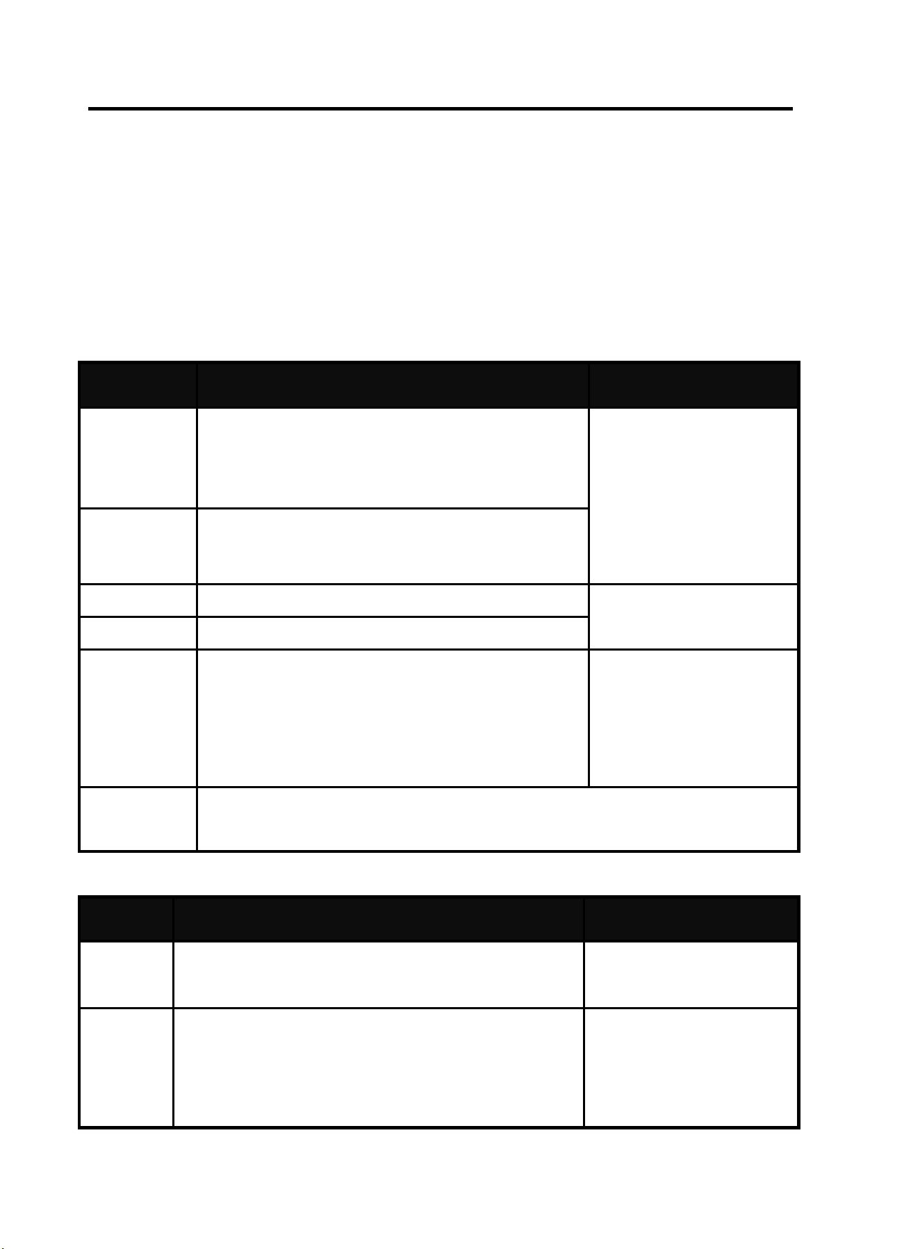
• Before Each Use -Check over machine and accessories for any obvious condition that may prevent
safe performance or operation, repair or replace items as necessary to correct any abnormal
condition.
• loose hardware
• misalignment or binding of moving parts
• damaged cord / electrical wiring
• frayed or damaged cables
• cracked or broken parts
• any other condition that may affect its safe operation.
• Store in a clean and dry location.
• For optimal weld quality, clean and inspect the contact tip and nozzle before each use.
Cleaning Tip and Nozzle- With the power switch OFF, keep the contact tip and nozzle clean to
prevent issues like shorted nozzles, poor welds, and overheating of the gun.
NOTE:
Make sure that the entire Mig gun is completely cool and that the power cord is unplugged from the
electrical outlet before proceeding.
Torch accessories are consumables, ARCCAPTAIN provided more for your replacement.
33
10.2 Daily maintenance
The power of the switching box and the welding machine should be shut down before daily checking
(except appearance checking without contacting the conductive body) to avoid personal injury accidents
such as electric shock and burns.
Daily checking is very important in keeping the high performance and safe operation of this welding
machine.
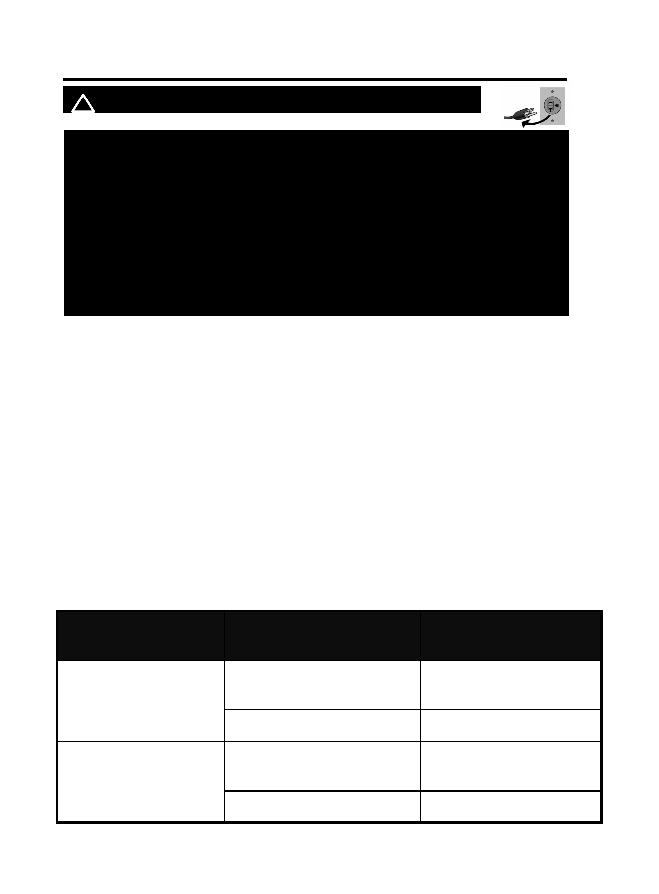
Do daily checking according to the table below, and clean or replace components when necessary.
In order to ensure the high performance of the machine, please choose components provided by
ARCCAPTAIN when replacing components.
Daily checking of the welding machine
Items
Checking requirements
Remarks
Front panel
Whether any of the components are damaged or
loosely connected;
Whether the output quick sockets are tightened;
Whether the abnormity indicator illuminates.
If unqualified, check the
interior of the machine,
and tighten or replace the
components.
Back panel
Whether the input power cable and buckle are in
good condition;
Whether the air intake is unobstructed.
Cover
Whether the bolts are loosely connected.
If unqualified, tighten or
replace the components.
Chassis
Whether the screws are loosely connected.
Routine
Whether the machine enclosure has color fading or
overheating problems;
Whether the fan sounds normal when the machine is
running;
Whether there is abnormal smell, abnormal vibration
or noise when the machine is running.
If abnormal, check the
interior of the machine.
Cleaning the
Feed Rolls
Clean the grooves in the drive rolls frequently. This can be done by using a small
wire brush. Also wipe off, or clean the grooves on the upper feed roll. After
cleaning, tighten the feed roll retaining knobs.
Daily checking of the cables
Items
Checking requirements
Remarks
Earth
cable
Whether the grounding wires (including workpiece
Earth wire and welding machine earth wire) break off.
If unqualified, tighten or
replace the components.
Welding
cable\
MIG gun
Whether the insulating layer of the cable is worn, or the
conductive part of the cable is exposed;
Whether the cable is drawn by an external force;
Whether the cable connected to the workpiece is well
connected.
Use appropriate methods
according to the work site
situation to ensure safety
and normal cutting.
34
11. TROUBLESHOOTING
! WARINING DO NOT set up without SWITCH OFF !
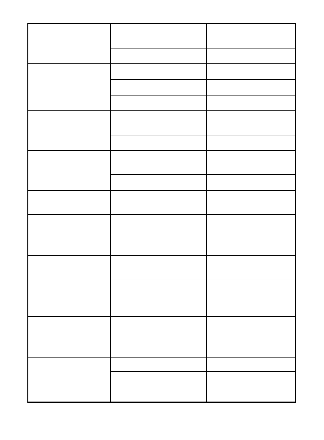
This Troubleshooting Guide is provided to help you locate and repair possible machine
malfunctions. Simply follow the three step procedure listed below.
Locate Problem(Symptom)
Look under the column labeled “PROBLEM(SYMPTOMS)”. This column describes possible symptoms
that the machine may exhibit. Find the listing that best describes the symptom that the machine is
exhibiting.
Possible Cause
The second column labeled “POSSIBLE CAUSE” lists the obvious external possibilities that may
contribute to the machine symptom.
Recommended Course of Action
This column provides a course of action for the Possible Cause, generally it states to contact you local
after-sales service center.
Problem (symptoms)
Possible areas of
mis-adjustment
Recommended course of
action
Bead is too
thick(intermittently)
Feeding speed is slow and/or
inconsistent
Increase and maintain a
constant feeding speed.
Output heat range is too high.
Set the knob to low
Bead does not penetrate
base metal.
Feeding speed is inconsistent.
Decrease and maintain a
constant feeding speed.
Output heat range is too low.
Set the knob to high
NOTICE: For safety and to maintain warranty validity:
Only qualified authorized personnel should perform service and repairs!
Unauthorized repairs may endanger the technician and machine operator!
To prevent electrical shock, follow all safety precautions in this manual!
Use only original spare parts when replacing components!
When ordering spare parts, provide machine type, serial number, and item
number, along with type designation and item number of the spare parts!
35
Wire sputters and sticks to
workpiece
The wire is damp.
Change to dry wire. Be sure wire
is stored in a dry location
Wire feed speed is too fast.
Reduce wire feed speed.
Edge of weld has ragged
depressions
Feeding speed is too fast.
Reduce feeding speed.
Wire feed speed is too fast.
Reduce wire feed speed.
Output heat range is too high
Set the knob to low
There is no current after
turning on the machine.
The power cord is not well
connected.
Reconnect the power cord.
The welding machine fails.
Ask professionals to check.
The fan does not work
during welding.
The power cord for the fan is not
well connected.
Reconnect the power cord for
the fan.
Auxiliary power fails.
Ask professionals to check.
The overheating indicator is
on.
The overheating protection circuit
works.
It can be recovered after the
machine cools down.
There is no response when
pushing the torch trigger
and the alarm indicator
does not illuminate.
The torch trigger fails.
Repair or replace the welding
torch.
When the torch trigger is
pushed, there is gas output,
but there is no output
current, and the alarm
indicator does not
illuminate.
The earth cable is not well
connected with the workpiece.
Reconnect it.
The torch trigger fails.
Repair or replace the welding
torch.
There is output current
when pushing the torch
trigger to feed gas, but the
wire feeder does not work.
The wire feeder is clogged.
Unclog it.
The wire feeder fails.
Repair it.
The control PCB or wire feeding
power PCB inside the machine
fails.
Replace it.
36
The welding current is
unstable.
The pressure arm on the wire
feeder is not properly adjusted.
Adjust it to get proper pressure.
The drive roll does not match the
wire size being used.
Make sure they match with each
other.
The contact tip of the welding torch
is badly worn.
Replace it.
The wire-feeding tube of the
welding torch is badly worn.
Replace it.
The electrode is of poor quality.
Use electrode of good quality.
Common Failure Analysis and Troubleshooting:
Common failure and troubleshooting
Failure
Cause
Solution
Turn on the
machine, there is
no current
● Power is not well connected
● Not holding down the MIG
gun switch continuously
● No Connect the polarity
changeover plug
● Reconnect power
● During MIG welding, it is necessary to
continuously press and hold the MIG gun switch
● Connect the polarity changeover plug,
According to the instruction manual.
Fan does not work
during welding
● Fan power cord is not well
connected
● Auxiliary power supply fails
● Reconnect fan power cord
● Ask professional personnel for help
Display “Err10”
● Over-current protection for
welder
● Restart the welder, if problem cannot be solved,
contact maintenance personnel
Display “Err14”
● Short-circuit current
protection
● Restart the welder, if problem cannot be solved,
contact maintenance personnel
Display “Err15”
● Power limitation protection
● Restart the welder, if problem cannot be solved,
contact maintenance personnel
Display “Err60”
● Overheat protection
● It gets to normal after cooling the welder
Display “Err34”
● 15V undervoltage
protection
●15V undervoltage protection
GMAW (MIG/MAG) failure and troubleshooting
Failure
Cause
Solution
There are no
response and error
code after pressing
torch trigger
● Torch is not well connected to
wire feeder
● Torch trigger fails
● Reconnect torch and wire feeder
● Repair or replace the torch
There are gas output
and wire feeding after
pressing torch trigger
● Ground wire is not well
connected to workpiece
● Wire feeding unit or torch fails
● Reconnect ground wire and workpiece
● Repair the wire feeding unit or torch
37
but no current output
and error code
There are gas supply
and current output but
no wire feeding after
pressing torch trigger
●Wire feeding unit is stuck
●Wire feeder fails
●Control board in the welder fails
● Unblock the wire feeding unit
● Repair the wire feeder
● Ask professional personnel for help
Welding current is
instable
●Unsuitable moment adjustment
for wire feeder
● Wire feed rolls do not match
welding wire
● Contact tip is worn severely
● Wire liner of torch is worn
severely
●Welding wire is of poor quality
● Readjust moment of wire feeder
● Select suitable wire feed rolls and
welding wire
● Replace the contact tip of torch
● Replace the wire liner
● Replace wire with one of better quality
If you do not understand or are unable to perform the Recommended Course of Action
safely, contact arccaptain.com for after-sale service.
Save for future reference:
Product:
Date Purchased:
Serial Number:
Product Feedback: