
Dear Valued Customer,
Thank you very much for being our valued customer. ARCCAPTAIN welder was built
by high quality components, every single unit machine was passed multiple industry
leading laboratory tests to provide a great welding experience and performance.
For your safety, please read and understand this manual carefully before using this
product. Your satisfaction is our priority! For any question or concerns, please do not
hesitate to contact ARCCAPTAIN for SUPPORT :
www.arccaptain.com

TABLE OF CONTENTS
1. SAFETY..................................................................................................................................... 1
2. PRODUCT INTRODUCTION ........................................................................................ 3
2.1 Function Overview ................................................................................................ 3
2.2 Duty Cycle .............................................................................................................. 3
2.3 Ordering Information and Packing ..................................................................... 3
2.4 Technical Parameters......................................................................................... 4
3. INSTALLATION AND OPERATION ..............................................................................5
3.1 Input Power Connection .......................................................................................5
3.2 Panel Display ......................................................................................................... 6
3.3 Wire Loading and Threading..............................................................................7
3.4 Installation and Operation for Flux-cored Welding..........................................9
3.5 MMA and TIG Operationg..................................................................................11
3.6 Welding Parameters Table................................................................................12
3.7 Strap Installation...............................................................................................13
3.8 FCAW Basic Welding Technique......................................................................14
3.9 Basic MIG Welding.............................................................................................14
4.0 Travel Speed.......................................................................................................16
4. MAINTENANCE .......................................................................................................... 17
4.1 Safety Matters .............................................................................. .......................17
4.2 Routine and Periodic Maintenance ............................................ ......................18
4.3 Daily Maintenance..............................................................................................18
5. TROUBLESHOOTING ................................................................................................ 19
1
1. SAFETY
Welding may cause damage to you and others. Please take good protection during welding. Please
refer to the operator safety guidelines in conformity with the accident prevention requirements of the
manufacturer for more details.
Only qualified personnel can operate this machine!
Please use welding protection appliances approved by
national safety supervision department.
All operators must be licensed and valid special operating
personnel for metal welding & cutting jobs.
Please cut off power supply while maintaining.
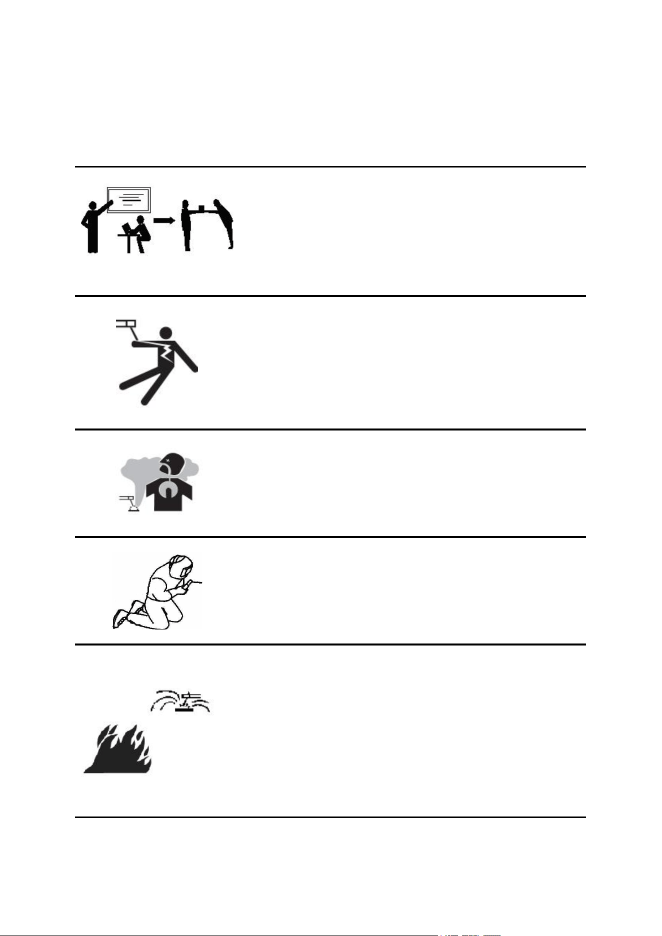
Electric shock-may result in serious injury or even death!
Install grounding device according to application standard.
Do not touch live parts with naked skin, wet gloves or wet
clothes.
Be sure you are insulated from ground and work piece.
Make sure all your working conditions are safe
Fume and gases can be dangerous!
Keep your head away from fumes and gases while in
welding.
Please use enough ventilation or exhaust to keep fumes and
gases away from the breathing zone.
Arc rays can burn!
Use suitable shield and clothing to protect your eyes and
body.
Protect other nearby personnel with suitable ,non-flammable
screening from being injured.
Improper operation may cause fire or explosion.
Welding spark may cause fire. Please make ensure there
are no inflammable in welding area, and always be alert to
fire safety.
Make sure there is fire extinguisher readily available and
welders are well trained to operate the fire extinguisher.
Do not weld air-tight container.
Do not use this machine for pipe unfreezing
2
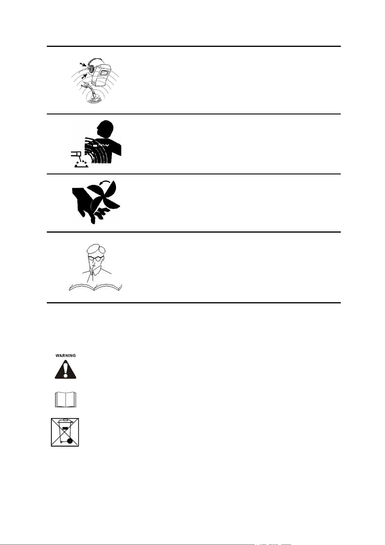
Excessive noise can be harmful to hearing.
Wear ear covers or other hearing protectors when welding.
Give warning to nearby personnel that noise may be
potentially hazardous to hearing.
Magnetic field can be harmful to pacemakers.
Electric current flowing through any conductor creates
electric and magnetic fields. Welders having peacemakers
should consult their doctor before operating this
equipment.
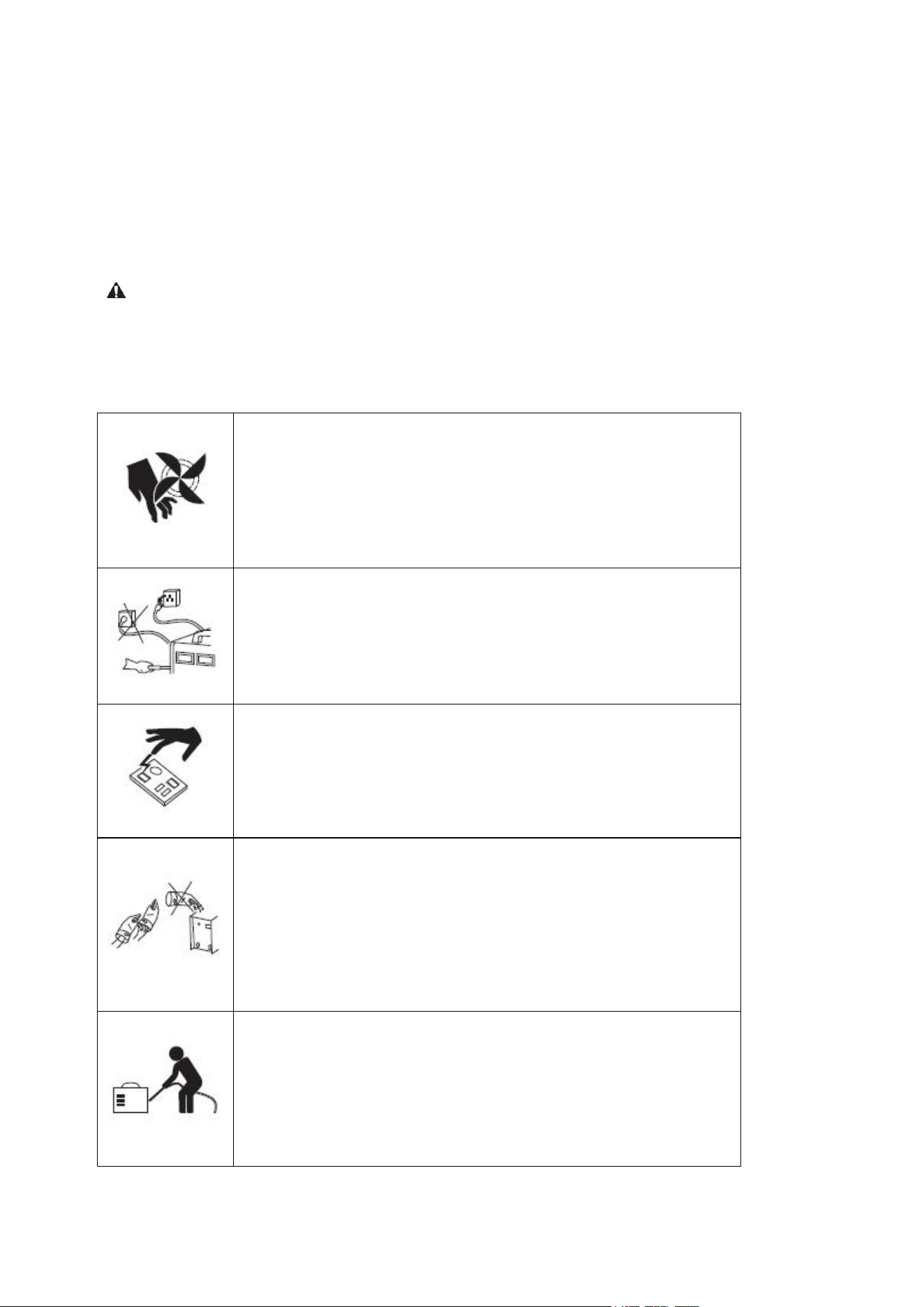
Moving parts may injure your body.
Please keep away from moving parts (such as fan).
All door, panel, cover, baffle plate, and other protective
device should be closed and well located.
Asking for professional support while trouble strikes.
When trouble strikes in installation and operation, please
resort to this manual for according contents.
If you are still in lost, or you still cannot solve the problem,
please contact the service center for professional support.
Symbol Description
Cautions in operation
Items need special instruction
It’s forbidden to dispose electric waste
with other ordinary waste. Please take
care of our environment.

3
2. PRODUCT INSTRUCTION
2.1 Function Overview
Synergic MIG: Automatically match voltage & wire feeding speed by adjusting wire
diameter.
3 in 1 Multi-functions: Gasless MIG/MMA /Lift TIG are available.
Advanced IGBT Inverter and MCU Technology: Improve welding performance.
Portable with Lightweight: Easy to carry with handle or shoulder strap.
Wire Feed Speed Adjustment: Meet your welding requirement.
Comes with attached MIG torch and input power cable.
Smart cooling fan, excellent heat dissipation.
VRD: Reduce the risk of electric shock to ensure operator’s safety.
Hot Start: Make the arc ignition in MMA welding easier and more reliable.
Arc Force: Obviously improve the performance of machine contribute to long-distance welding.
Anti-stick: Improve welding performance to prevent stickiness.
Multiple Protection: Built-in overheating, over-current, over-voltage, overloading protection.
2.2 Duty Cycle
The rated duty cycle of a welding power source, is a statement of the time it may be operated at its
rated welding current output without exceeding the temperature limits of the insulation of the
component parts. To explain the 10 minute duty cycle period the following example is used.
Suppose a welding power source is designed to operate at a 60% duty cycle, 130 amperes at 20
volts. This means that it has been designed and built to provide the rated amperage (130A) for 6
minutes, i.e. Arc welding time, out of every 10 minute period (60% of 10 minutes is 6minutes).
During the other 4 minutes of the 10 minute period the welding power source must idle and be
allowed to cool.
2.3 Ordering Information and Packing
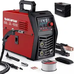
1* ARCCAPTAIN MIG130 Welder
1* 10ft MIG Welding Torch
1* 10ft Ground Clamp
1* 10ft Electronic Holder
1* .030"/2lb Flux Cored Wire
1* 0.8mm/.030" Conduct Nozzle
1* 0.9mm/.035" Conduct Nozzle
1* Brush&Hammer
1* User Manual
1* Strap

4
2.4 Technical Parameters
Items
Model
MIG130
Rated input voltage
Single-phase AC110V
50Hz/60Hz
Rated input power (KVA)
5
Welding current range
(MIG,MMA,TIG)
20-130A
Welding voltage range
(MIG,MMA,TIG)
16-20.5V (MIG)
20.8-25.2V(MMA)
10.8V-15.2V(TIG)
Rated duty cycle
60%
No-load voltage (V)
65
Applicable wire
/electrode
0.8/0.9/1.0mm
1.6-3.2mm (1/16"-1/8")
Housing protection grade
IP21S
Insulation grade
H
Power factor(COSφ)
0.68
Cooling mode
Air cooling
Overall efficiency
85%
Dimension
380*135 *247 mm
14.9*5.3*9.7 in
Weight
5.35kg/11.79lb

5
3. INSTALLATION AND OPERATION
3.1 Input Power Connection
1) The machine has one input connection,the power input cable. The power input cable is located
on the rear.
2) The MIG130 is provided with a 110V cables, 2.0M in length, with a 16Amp 5-15P plug molded
onto the cord;
3) The rated output of the MIG130 is available when connected to a 40A branch circuit. when
connected to a branch circuit with lower capacity, lower welding current and duty cycle must be
used.
4) The primary cable should be tightly connected to the correct socket to avoid oxidization.
5) Check whether the voltage value varies in acceptable range with a multi-meter.
6) The mains supply voltage should be within ±15% of the rated mains supply voltage. Low voltage
may cause poor welding performance.Too high a supply voltage will cause components to overheat
and possibly fail.
Note: Code Requirements for Electrical Input Connections
This welding machine must be connected to a power source in accordance with applicable
electrical codes.
The National Electrical Code provides standards for amperage handling capability of supply
conductors based on duty cycle of the welding source.
If there is any question about the installation meeting applicable electrical code
requirements,consult a qualified electrician.
Note: Do not remove the power cord ground prong.
6
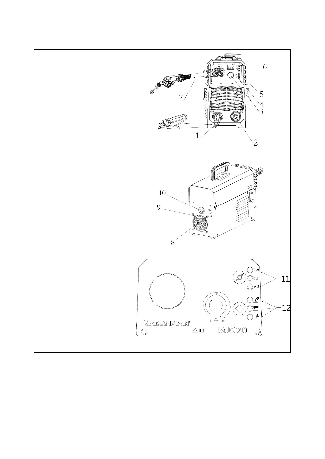
3.2 Panel Display
1.Positive Welding Terminal(+)
2. Negative Welding Terminal(-)
3. Synergic Knob
4. Welding Mode Button
5. Wire Selection Button
6. Display Meter
7. Flux MIG Torch
8.Power Switch
9. Cooling Fan
10. Power Input Cable
11.Wire Selection 0.8/0.9/1.0 LED
12.Welding Mode MIG/MMA/TIG
LED
7
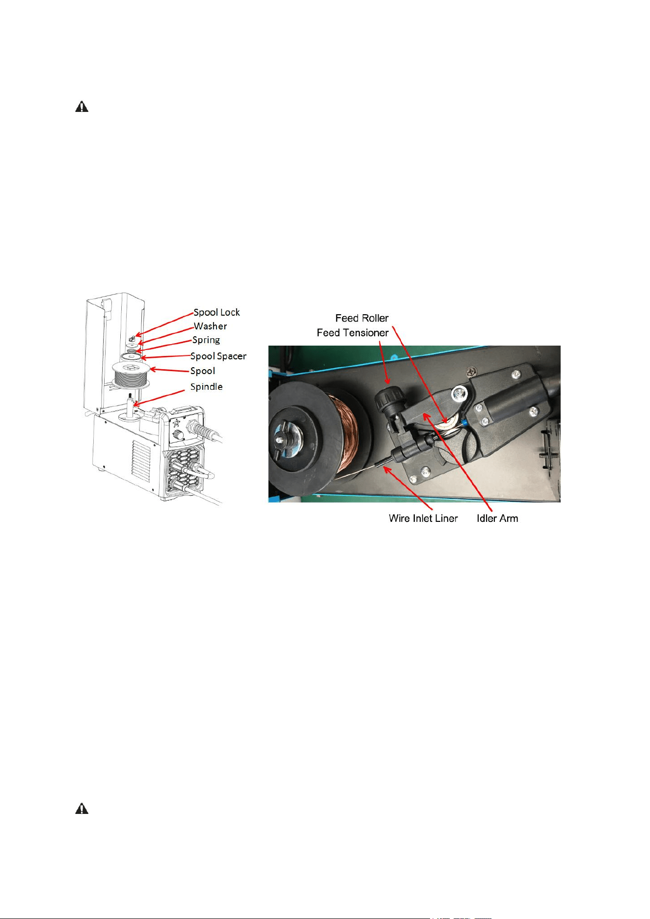
3.3 Wire Loading and Threading
Turn machine power switch to the OFF(“0”)position before working inside the wire feed
enclosure.Make sure that the wire feed drive roll and the contact tip of the gun match the diameter
and type of wire used.
Installation of Wire Spool
1) Push the spool onto the spindle so that the wire deeds off the bottom of the spool, toward the
drive roll.
2) Push the spool spacer onto the spindle, against the spool.
3) Slide the spring onto the spool, then press on the spool lock, turning it clockwise to lock the
spool assembly onto the spindle.
Wire Threading Details
1) Release Feed Tensioner and rotate the Idler Arm away from the Feed Roller. Ensure that the
visible, stenciled size on the drive roll side facing you matches the wire size being used.
2) Carefully detach the end of the wire from the spool. Maintain tension on the wire to prevent the
spool from unwinding and do not release the wire until after step 8).
3) Cut the bent portion of wire off and straighten the first 4”(100mm).
4) Thread the wire through the Wire Inlet Liner, over the Feed Roller, and into the gun liner.
5) Close the Idler Arm and turn down the Feed Tensioner until the idle roller presses down firmly
on the wire. (Now you may release the welding wire ). Make sure the wire is positioned in the
groove of the lower feed roller.
6) The Feed Tensioner on the Idler Arm adjusts the pressure on the wire .Adjust pressure by
turning the Feed Tensioner to prevent spool overrun, but still allow smooth and easy wire feeding.
Start with the pressure set to an intermediate value. Readjust, if necessary. If the drive roll slips
while feeding wire, the pressure should be increased until the wire feeds properly.
When feeding the welding wire through the gun, the feed roller, the gun connector block and the
gun contact tip are always energized relative to work and ground.
8
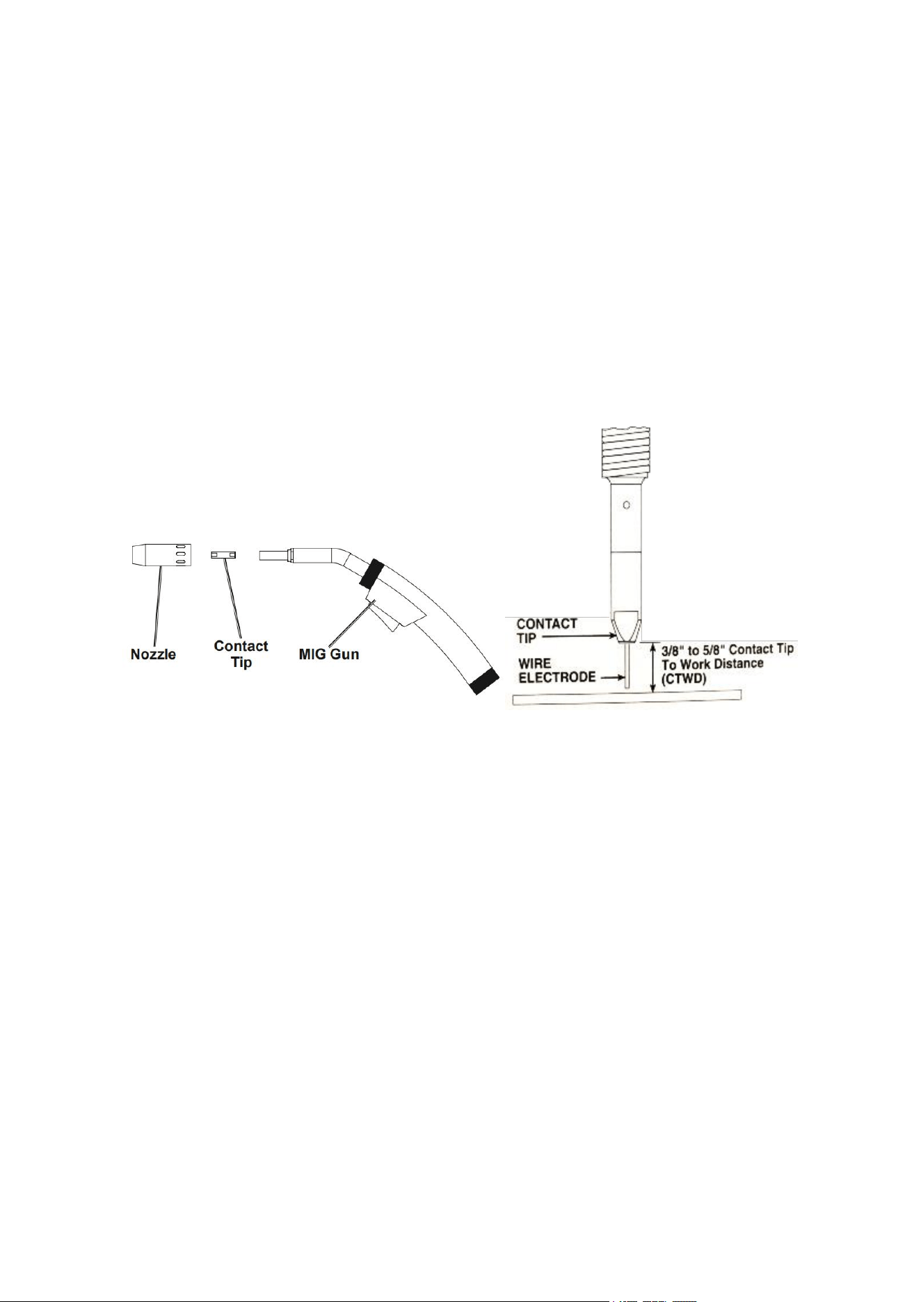
Wire Stick Out
7) Remove the contact tip and nozzle from the gun.
8) Turn the machine ON(“1”).
9) Straighten the gun cable assembly.
10) Depress the gun trigger switch and feed welding wire through the gun and cable. (Point the gun
away from yourself and others while feeding wire). Release the gun trigger after wire appears at the
end of the gun.
11)Turn off the machine.
12) Install the nozzle and contact tip. Refer to Figure 4. Cut the wire off so the 3/8” to 5/8”(10-15mm)
protrudes from the end of the tip.
13) Turn on the machine. The machine is now ready to weld.
9
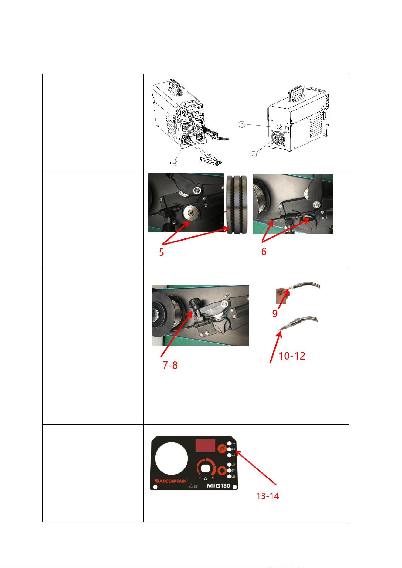
3.4 Installation and Operation For MIG Flux-Cored Welding
Installation
1) Turn off the Power switch
2)Connect power cable to the
negative socket
3/4) Connect earth clamp lead to+
5)Fit the correct sized Knurled
Driver roller for Gas Less Flux
Cored wire
6)Place wire onto spool
holder(spool retaining nut is top
thread) Feed the wire through the
inlet guide tube on to the drive
roller
7-8) Close down the top roller
bracket and clip the pressure arm
into place. Apply a medium amount
of pressure to the drive roller
9) Remove the gas nozzle and
contact tip from the front end of the
MIG torch
10-12) Fit the correct size contact
tip over the wire and fasten tightly
into tip holder
13-14) Select the correct sized
wire diameter and set the welding
parameter

10
Operation
1) Switch the Power Source ON/OFF switch located on the rear of the power source to the OFF
position.
2) Connect the weld power cable to the Negative socket and tighten it.
3) Connect the earth cable plug into the Positive socket and tighten it.
Important: Loose welding terminal connections can cause overheating and result in the male,
plug being fused in the terminal. Remove any packaging material prior to use. Do not block the air
vents at the front or rear of the Welding Power Source.
4) Check the Weld Power Cable is connected to the Negative terminal.
5) Fit the correct size Knurled drive roller for Gas less Flux Core wire.
6) Place the Wire Spool onto the Spool Holder
Note: The spool retaining nut is top thread. Snip the wire from the spool being sure to hold the wire
to prevent rapid uncoiling.Feed the wire into the wire feeder inlet guide tube through to the
drive roller.
7) Carefully feed the wire over the drive roller into the outlet guide tube about 150mm .
8) Align the wire into the groove of the drive roller and close down the top roller making sure the
wire is in the groove of the bottom drive roller, lock the Feed Tensioner into place.
Note: Apply a light amount of pressure to the Feed Roller. Too much pressure will crush the cored
wire.
9) Remove the gas nozzle and contact tip from the torch neck.
10) Switch the Power Source ON/OFF switch located on the rear of the Power Source to the ON
position and the display in the front panel is illuminated.
11) Press and hold the MIG Torch switch to feed the wire through to the torch neck.
12) Fit the correct sized contact tip and feed the wire through it, screw the contact tip into the tip
holder of the torch head and nip it up tightly.
Note: Not install the gas nozzle to the torch head.
13) Select the correct sized wire diameter.
14) Select welding parameter required on “synergic” knob, based on the material ,thickness of the
work piece.
11
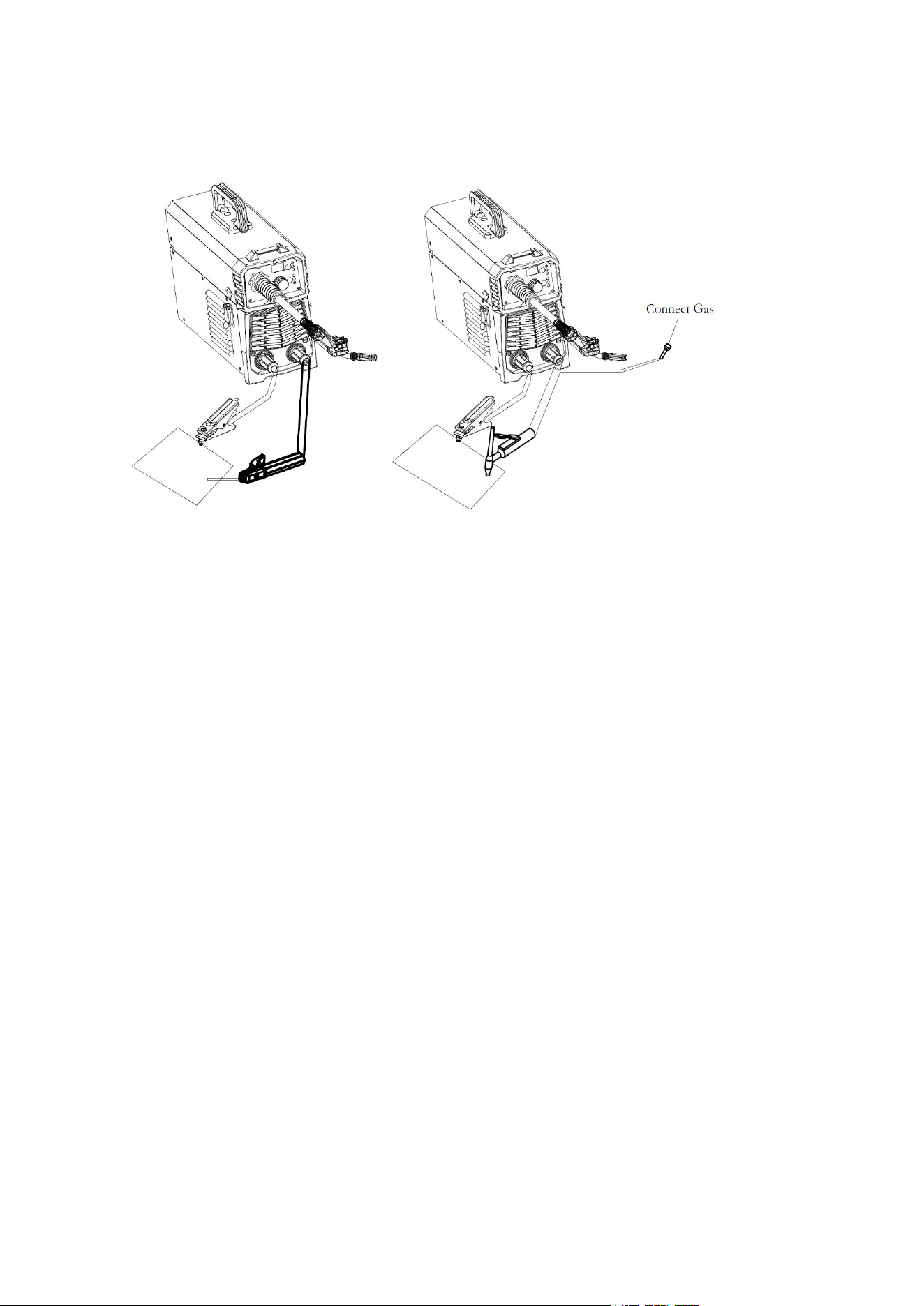
3.5 MMA and TIG Operation
(MMA) (TIG)
1) A primary power supply cable is available for this welding machine. Connect the power supply
cable to the rated input power.
2) The primary cable should be tightly connected to the correct socket to avoid oxidization.
3) Check whether the voltage value varies in acceptable range with a multi-meter.
4) Insert the cable plug with electrode holder into the “-” socket on the front panel of the welding
machine, and tighten it clockwise.
5) Insert the cable plug with earth clamp into the “+” socket on the front panel of the welding
machine, and tighten it clockwise.
6) Ground connection is needed for safety purpose.The connection as mentioned above in 4) and
5) is DCEN connection. Operator can choose DCEP connection according to workpiece and
electrode application requirement. Generally, DCEP connection is recommended for basic
electrode, while there is no special requirement for acid electrode.
7) Insert the cable plug with TIG Welding torch into the “-” socket on the front panel of the welding
machine, and tighten it clockwise.
8) Insert the cable plug with earth clamp into the “+” socket on the front panel of the welding
machine, and tighten it clockwise.

12
3.6 Welding parameters table
1) MIG Welding parameters table(for reference only)
Note: This table is suitable for mild steel welding. For other materials, consult related materials and welding
process for reference.
2) MMA Welding parameters table(for reference only)
Electrode Diameter(mm)
Recommended Welding Current(A)
Recommended welding voltage(V)
1.6
30~70
21.2~22.8
2.0
40~90
21.6~23.6
2.5
50~100
22~24
3.2
80~120
22.4~24.8
Note: This table is suitable for mild steel welding. For other materials, consult related materials and welding
process for reference.
3) Parameters for TIG welding on stainless steel (for reference only)
Plate
thickness
(mm)
Weldin
g
layers
Electrode
diameter
(mm)
Wire
diamet
er
(mm)
Welding
current
(A)
Gas flow (L/min)
Nozzle
diamete
r
(mm)
Square
groove
Single V groove
with root face
Double V groove
with root face
0.5
1.0
1.5
2.0
2.5
3.0
1
1
1
1
1
1~2
1.5
2.0
2.0
2.0~3.0
2.0~3.0
3.0
1.0
1.0~2.0
1.0~2.0
1.0~2.0
2.0
2.0~3.0
30~50
40~60
60~80
80~110
110~120
110~120
8~10
8~10
10~12
12~14
12~14
12~14
6~8
6~8
8`10
10~12
10~12
10~12
14~16
14~16
14~16
16~20
16~20
16~20
10
10
10~12
12~14
12~14
14~18
Note: This table is suitable for stainless steel welding. For other materials, consult related materials and welding
process for reference.
Material
Wire
Type
Drive Roller
Polarity
Gas Type
Wire Ø
Material Thickness
1mm
2mm
3mm
mild Steel
E71T-
GS
Knurled
Dcep
NO Gas
0.8/0.9/1.
0
40-70
70-100
100-120A
13
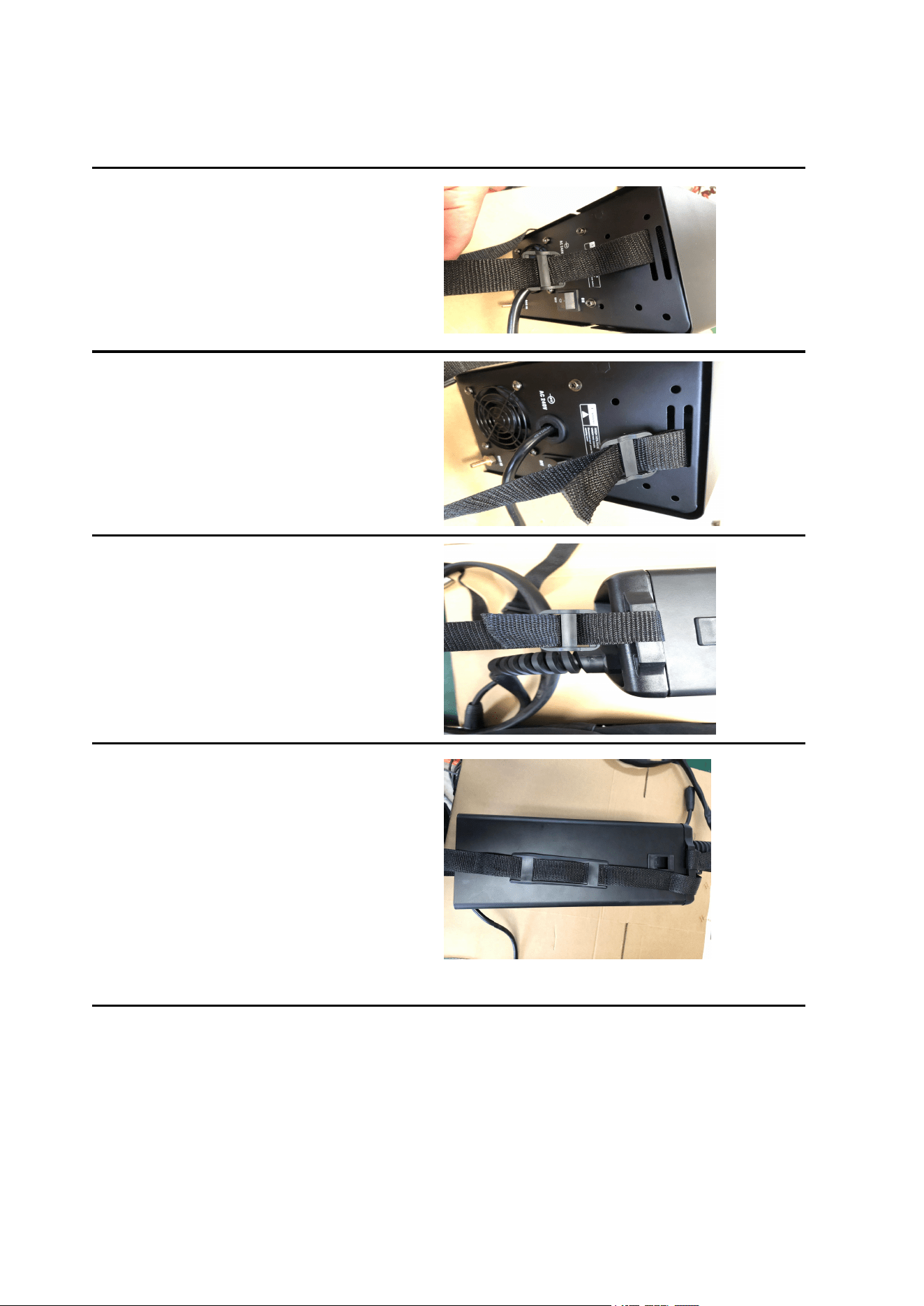
3.7 Strap Installation
Step 1: Pull out one side through the strap
hole on the back panel with hook side of the
velcro up.
Step 2: Pull out it to well stick hook side of the
velcro to loop side and across the nylon
buckle.
Repeat it on the other side.
Step 3: Repeat it on the front panel. Pull out
one side through the strap hole on the back
panel with hook side of the velcro up.
Pull out it to well stick hook side of the velcro
to loop side and across the nylon buckle.
Step 4: Proper state after installation:
1. Strap does not twist;
2. Buckle side of shoulder pad is up, while its
flat side faces the machine (as shown in the
picture);
3. Straps are well locked.

14
3.8 FCAW Basic Welding Technique
Flux Cored Arc Welding(FCAW)
This is an electric arc welding process which fuses together the parts to be welded by heating them
with an arc between a continuous flux filled electrode wire and the work. Shielding is obtained
through decomposition of the flux within the tubular wire. Additional shielding may or may not be
obtained from an externally supplied gas or gas mixture. The process is normally applied semi
automatically; however the process may be applied automatically or by machine. It is commonly
used to weld large diameter electrodes in the flat and horizontal position and small electrode
diameters in all position. The process is used to a lesser degree for welding stainless steel and for
overlay work.
Weld at a Steady Pace do not weave the arc, neither forward,backward,of sideways remove slag
with the Chipping Hammer to expose weld for Horizontal Weld Joins.
Remember:Drag if there’s Slag ,Refer to manual for Troubleshooting Poor Weld Quality.
Adjustable Variables
1) Stick-out (distance between the end of the contact tube (tip) and the end of the electrode
wire). Maintain at about 10mm stick-out.
2) Wire Feed Speed. Increase in wire feed speed increases weld current ,Decrease in wire feed
3) speed decreases weld current.
4) Nozzle Angle. This refers to the position of the welding gun in relation to the joint. The transverse
angle is usually one half the included angle between plates forming the joint. The longitudinal angle
is the angle between the center line of the welding gun and a line perpendicular to the axis of the
weld. The longitudinal angle is generally called the Nozzle Angle and can be either trailing (pulling)
or leading (pushing). Whether the operator is left handed or right handed has to be considered to
realize the effects of each angle in relation to the direction of travel.
Establishing the Arc and Making Weld Beads
1) Before attempting to weld on a finished piece of work, it is recommended that practice welds be
made on a sample metal of the same material as that of the finished piece.
2) The easiest welding procedure for the beginner to experiment with MIG welding is the flat
position. The equipment is capable of flat, vertical and overhead positions.
3) For practicing MIG welding, secure some pieces of 1.5mm or 2.0mm mild steel plate 150X
150mm. Use 0.8mm flux cored gas less wire or a solid wire with shielding gas.
3.9 Basic MIG Welding
Good weld quality and weld profile depends on gun angle, direction of travel, electrode extension
(stick out), travel speed, thickness of base metal, wire feed speed (amperage) and arc voltage. To
follow are some basic guides to assist with your setup.
1) Gun Position -ravel Direction, Work Angle
Gun position or technique usually refers to how the wire is directed at the base metal, the angle and
travel direction chosen.Travel speed and work angle will determine the characteristic of the weld
bead profile and degree of weld penetration.
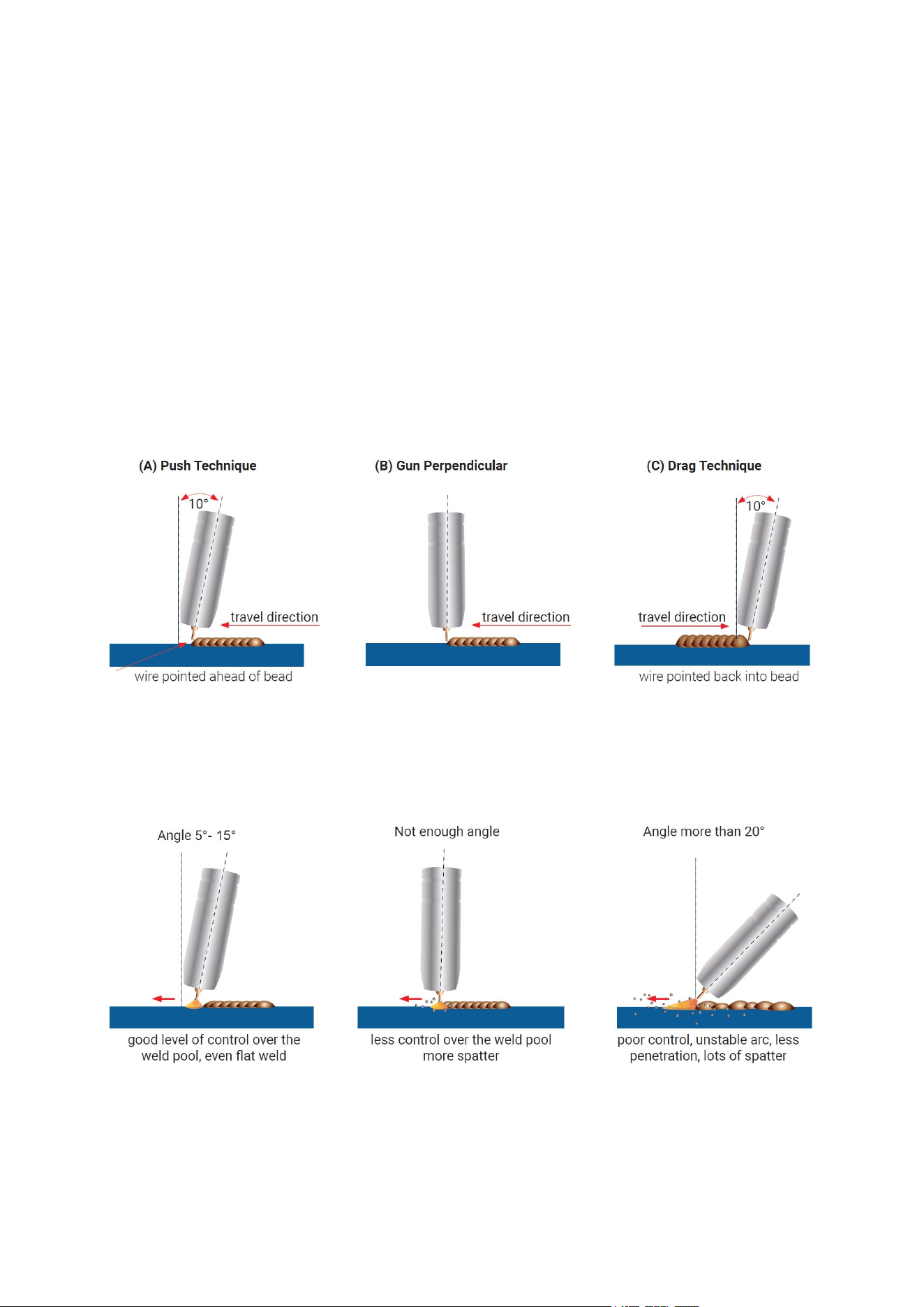
15
(A) Push Technique
The wire is located at the leading edge of the weld pool and pushed towards the un-melted work
surface. This technique offers a better view of the weld joint and direction of the wire into the weld
joint. Push technique directs the heat away from the weld puddle allowing faster travel speeds
providing a flatter weld profile with light penetration - useful for welding thin materials. The welds are
wider and flatter allowing for minimal clean up / grinding time.
(B) Perpendicular Technique
The wire is fed directly into the weld, this technique is used primarily for automated situations or
when conditions make it necessary. The weld profile is generally higher and a deeper penetration is
achieved.
(C) Drag Technique
The gun and wire are dragged away from the weld bead. The arc and heat are concentrated on the
weld pool, the base metal receives more heat, deeper melting, more penetration and the weld
profile is higher with more build up.
2) Travel Angel
Travel angle is the right to left angle relative to the direction of welding. A travel angle of 5°- 15° is
ideal and produces a good level of control over the weld pool. A travel angle greater that 20° will
give an unstable arc condition with poor weld metal transfer, less penetration, high levels of spatter,
poor gas shield and poor quality finished weld.
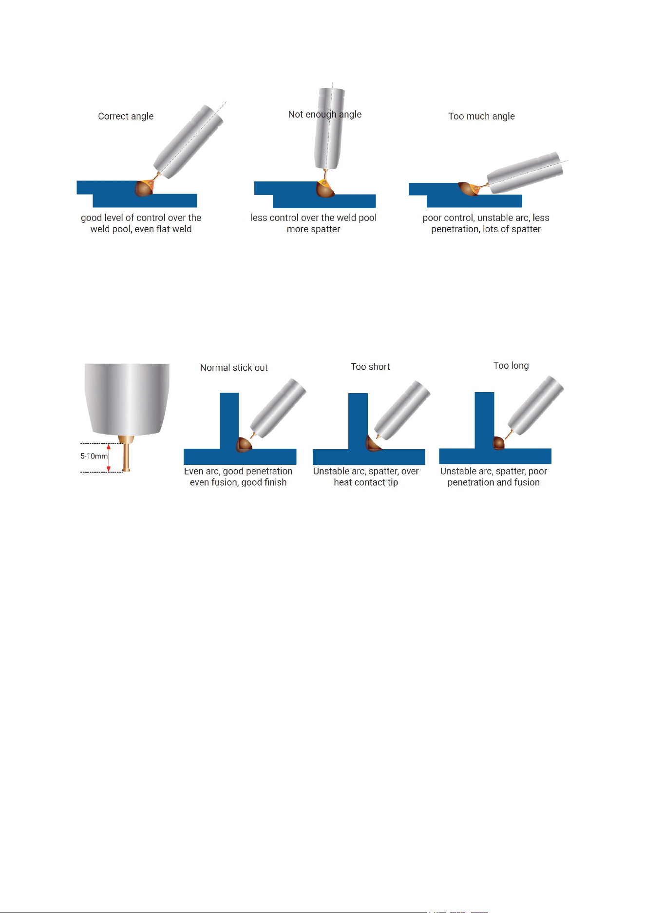
3) Angle to Work
The work angle is the forward back angle of the gun relative to the work piece.The correct work
angle provides good bead shape, prevents undercut, uneven penetration, poor gas shield and poor
quality finished weld.
16
4) Stick Out
Stick out is the length of the unmelted wire protruding from the end of the contact tip. A constant
even stick out of 5-10mm will produce a stable arc, and an even current flow providing good
penetration and even fusion. Too short stick out will cause an unstable weld pool, produce spatter
and over heat the contact tip. Too long stick out will cause an unstable arc, lack of penetration, lack
of fusion and increase spatter.
4.0 Travel Speed
Travel speed is the rate that the gun is moved along the weld joint and is usually measured in mm
per minute. Travel speeds can vary depending on conditions and the welders skill and is limited to
the welders ability to control the weld pool. Push technique allows faster travel speeds than Drag
technique. Gas flow must also correspond with the travel speed, increasing with faster travel speed
and decreasing with slower speed. Travel speed needs to match the amperage and will decrease
as the material thickness and amperage increase.
1) Too Fast Travel Speed
A too fast travel speed produces too little heat per mm of travel resulting in less penetration and
reduced weld fusion, the weld bead solidifies very quickly trapping gases inside the weld metal
causing porosity. Undercutting of the base metal can also occur and an unfilled groove in the base
metal is created when the travel speed is too fast to allow molten metal to flow into the weld crater
created by the arc heat.
2) Too Slow Travel Speed
A too slow travel speed produces a large weld with lack of penetration and fusion. The energy from
the arc dwells on top of the weld pool rather than penetrating the base metal. This produces a wider
weld bead with more deposited weld metal per mm than is required resulting in a weld deposit of
poor quality.
3) Correct Travel Speed
The correct travel speed keeps the arc at the leading edge of the weld pool allowing the base metal
17
to melt sufficiently to create good penetration, fusion and wetting out of the weld pool producing a
weld deposit of good quality.
4.
MAINTENANCE
4.1 Safety Matters
Periodic check should be carried out by qualified professionals to ensure safety. The power of
the switching box and the welding machine should be shut down before periodic check to avoid
personal injury accidents such as electric shock and burns. Due to the discharge of capacitors,
checking should be carried out 5 minutes after the machine is powered off.
Tips:
Safety
All maintenance and checking should be carry out after the power is
completely cut off. Make sure the power plug of the machine is
pulled out before uncovering the welding machine.
When the machine is powered on, keep hands, hair and tools away
from the moving parts such as the fan to avoid personal injury or
machine damage.
Periodic check
Check periodically whether inner circuit connection is in good
condition (esp. plugs). Tighten the loose connection. If there is
oxidization, remove it with sandpaper and then reconnect.
Check periodically whether the insulating layer of all cables is in
good condition. If there is any dilapidation, rewrap it or replace it.
Beware of static
In order to protect the semiconductor components and PCBs from
the static damage, please wear antistatic device or touch the metal
part of the enclosure to remove static in advance before contacting
the conductors and PCBs of the machine internal wiring.
Keep it dry
Avoid rain, water and vapor infiltrating the machine. If there is, dry it
and check the insulation of the welding machine (including that
between the connections and that between the connection and the
enclosure) with an ohmmeter. Only when there are no abnormal
phenomena anymore, can the machine be used.
Put the machine into the original packing in dry location if it is not to
be used for a long time.
Pay attention to maintenance
Periodic check should be carried out to ensure the long-term normal
use of the machine. Be careful when doing the periodic check,
including the inspection and cleaning of the machine interior.
Generally, periodic check should be carried out every 6 months, and
it should be carried out every 3 months if the welding environment is
dusty or with heavy oily smoke.

18
4.2 Routine and Periodic Maintenance
1) Before Each Use -Check over machine and accessories for any obvious condition that may
prevent safe performance or operation,repair or replace items as necessary to correct any
abnormal condition.
AFTER 5 MINUTES OF WELDING OR WHEN SPATTER ACCUMULATES ON THE CONTACT
TIP:
4) Cleaning Tip and Nozzle- With the power switch in the OFF position,keep the contact tip and
nozzle clean to avoid are bridging between them. Bridging can result in a shorted nozzle, poor
welds and an overheated gun. Hint:Anti-stick spray or gel, available from a welding supplier, may
reduce buildup and aid in spatter removal.
4.3 Daily maintenance
The power of the switching box and the welding machine should be shut down before daily
checking (except appearance checking without contacting the conductive body) to avoid personal
injury accidents such as electric shock and burns.
1) Daily checking is very important in keeping the high performance and safe operation of this
welding machine.
2) Do daily checking according to the table below, and clean or replace components when
necessary.
3) In order to ensure the high performance of the machine, please choose components provided
or recommended by producer when replacing components.
Daily checking of the welding machine
Items
Checking requirements
Remarks
Front panel
Whether any of the components are
damaged or loosely connected;
Whether the output quick sockets are
tightened;
Whether the abnormity indicator illuminates.
If unqualified, check the
interior of the machine,
and tighten or replace the
components.
Back panel
Whether the input power cable and buckle
are in good condition;
Whether the air intake is unobstructed.
Cover
Whether the bolts are loosely connected.
If unqualified, tighten or
replace the components.
Chassis
Whether the screws are loosely connected.
Routine
Whether the machine enclosure has color
fading or overheating problems;
Whether the fan sounds normal when the
machine is running;
Whether there is abnormal smell, abnormal
vibration or noise when the machine is
running.
If abnormal, check the
interior of the machine.
Cleaning the
Feed Rolls
Clean the grooves in the drive rolls frequently.This can be done by using
a small wire brush.Also wipe off, or clean the grooves on the upper feed
roll. After cleaning,tighten the feed roll retaining knobs.

19
Daily checking of the cables
Items
Checking requirements
Remarks
Earth cable
Whether the grounding wires (including
workpiece Earth wire and welding machine
earth wire) break off.
If unqualified, tighten or
replace the components.
Welding
cable\ MIG
gun
Whether the insulating layer of the cable is
worn, or the conductive part of the cable is
exposed;
Whether the cable is drawn by an external
force;
Whether the cable connected to the
workpiece is well connected.
Use appropriate methods
according to the work site
situation to ensure safety
and normal cutting.
5. TROUBLESHOOTING
Service and Repair should only be performed by qualified authorized personnel; Unauthorized
repairs performed on this equipment may result in danger to the technician and machine operator
and will invalidate your factory warranty. For your safety and to avoid Electrical Shock,please
observe all safety noted and precautions detailed throughout this manual.When replacing parts,use
only original spare parts.When ordering spare parts,please quote the machine type,serial number
and item number of the machine,as well as the type designation and item number of the spare part.
This Troubleshooting Guide is provided to help you locate and repair possible machine
malfunctions. Simply follow the three step procedure listed below.
1) Locate Problem(Symptom)
Look under the column labeled “PROBLEM(SYMPTOMS)”. This column describes possible
symptoms that the machine may exhibit. Find the listing that best describes the symptom that the
machine is exhibiting.
2) Possible Cause
The second column labeled “POSSIBLE CAUSE” lists the obvious external possibilities that may
contribute to the machine symptom.
3) Recommended Course of Action
This column provides a course of action for the Possible Cause, generally it states to contact you
local after-sales service center.
If you do not understand or are unable to perform the Recommended Course of Action safely,
contact your local after-sales service center.
4) Electric Shock can kill
Turn off machine at the disconnect switch on the rear of the machine and remove main power
supply connections before doing any troubleshooting.

20
5) Observe all Safety Guidelines detailed throughout this manual
Problem
(symptoms)
Possible areas of
mis-adjustment
Recommended course of action
Bead is too
thick(intermittently)
Travel speed is slow and/or
inconsistent
Increase and maintain a constant travel
speed.
Output heat range is too high.
Set the knob to low
Bead does not
penetrate base
metal.
Travel speed is inconsistent.
Decrease and maintain a constant travel
speed.
Output heat range is too low.
Set the knob to high
Wire sputters and
sticks to workpiece
The wire is damp.
Change to dry wire.Be sure wire is stored
in a dry location
Wire feed speed is too fast.
Reduce wire feed speed.
Edge of weld has
ragged depressions
Travel speed is too fast.
Reduce travel speed.
Wire feed speed is too fast.
Reduce wire feed speed.
Output heat range is too high
Set the knob to low
There is no current
after turning on the
machine.
The power cord is not well
connected.
Reconnect the power cord.
The welding machine fails.
Ask professionals to check.
The fan does not
work during welding.
The power cord for the fan is
not well connected.
Reconnect the power cord for the fan.
Auxiliary power fails.
Ask professionals to check.
The overheating
indicator is on.
The overheating protection
circuit works.
It can be recovered after the machine cools
down.
There is no response
when pushing the
torch trigger and the
alarm indicator does
not illuminate.
The torch trigger fails.
Repair or replace the welding torch.
When the torch
trigger is pushed,
there is gas output,
The earth cable is not well
connected with the
workpiece.
Reconnect it.

21
but there is no output
current, and the
alarm indicator does
not illuminate.
The torch trigger fails.
Repair or replace the welding torch.
There is output
current when
pushing the torch
trigger to feed gas,
but the wire feeder
does not work.
The wire feeder is clogged.
Unclog it.
The welding current
is unstable.
The wire feeder fails.
Repair it.
The control PCB or wire
feeding power PCB inside the
machine fails.
Replace it.
The pressure arm on the wire
feeder is not properly
adjusted.
Adjust it to get proper pressure.
The drive roll does not match
the wire size being used.
Make sure they match with each other.
The contact tip of the welding
torch is badly worn.
Replace it.
The wire-feeding tube of the
welding torch is badly worn.
Replace it.
The electrode is of poor
quality.
Use electrode of good quality.
WIRING DIAGRAM

22