VERSION A3
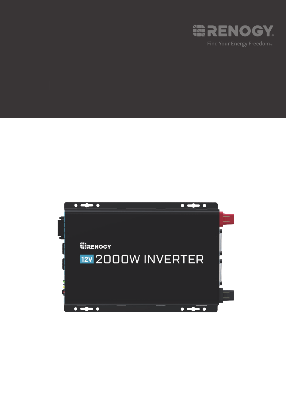
PGH1 Series
Battery Power Inverter
Renogy
12V
1000W/2000W/3000W
USER MANUAL

Applicability
The user manual applies to the following products:
z
Renogy PGH1 12V 1000W Battery Power Inverter (PGH1-10111S)
z
Renogy PGH1 12V 2000W Battery Power Inverter (PGH1-20111S)
z
Renogy PGH1 12V 3000W Battery Power Inverter (PGH1-30111S)
Disclaimer
z
Renogy ensures the accuracy, sufficiency, and the applicability of information in the user
manual at the time of printing due to continual product improvements that may occur.
z
Renogy assumes no responsibility or liability for personal and property losses, whether
directly and indirectly, caused by the user
’
s failure to install and use the product in
compliance with the user manual.
z
Renogy is not responsible or liable for failures, damages, or injuries resulting from repair
attempted by unqualified personnel, improper installation and operation.
z
The illustrations in the user manual are for demonstration purposes only. Details may
appear slightly different depending on product revision and market region.
z
Renogy reserves the right to change the information in the user manual without notice.
For the latest user manual, visit renogy.com.
Copyright
Renogy PGH1 Series Battery Power Inverter User Manual © 2022 Renogy. All rights
reserved. All information in the user manual is subject to copyright and other intellectual
property rights of Renogy and its licensors. The user manual may not be modified,
reproduced, or copied, in whole or in part, without the prior written permissions of Renogy
and its licensors.
Trademark
The following are registered trademarks of Renogy:
RENOGY
The registered trademarks in the user manual are the property of Renogy. The unauthorized
use of the trademarks is strictly prohibited.
Date and Revision
October 2022, Revision A3

Table of Contents
Important Safety Information .......................................................................................................... 01
Symbols Used .......................................................................................................................... 01
General Safety Information ...................................................................................................... 01
Overview......................................................................................................................................... 03
Introduction .............................................................................................................................. 03
Key Features ............................................................................................................................ 03
Pure Sine Wave ....................................................................................................................... 03
Package Contents .......................................................................................................................... 04
Included Components .............................................................................................................. 04
Optional Components .............................................................................................................. 04
Product Overview ........................................................................................................................... 05
Identification of Parts (AC Side) ............................................................................................... 05
Identification of Parts (DC Side) ............................................................................................... 06
Installation ...................................................................................................................................... 07
Location Recommendations ..................................................................................................... 07
Sizing your Battery Bank .......................................................................................................... 08
Wiring ............................................................................................................................................. 09
Grounding ................................................................................................................................ 09
DC Wiring ................................................................................................................................. 09
AC Wiring ..................................................................................................................................11
Fusing ...................................................................................................................................... 13
Operation ........................................................................................................................................ 14
AC Side Operation ................................................................................................................... 14
LED Overview .......................................................................................................................... 14
Wired Remote .......................................................................................................................... 15
DIP Switches ............................................................................................................................ 15
Troubleshooting .............................................................................................................................. 16
Technical Specifications ................................................................................................................. 18
Dimensions ..................................................................................................................................... 20

1000W Inverter (PGH1-10111S) .............................................................................................. 20
2000W Inverter (PGH1-20111S) .............................................................................................. 20
3000W Inverter (PGH1-30111S) .............................................................................................. 21
Maintenance ................................................................................................................................... 22
Inspection ................................................................................................................................. 22
Cleaning ................................................................................................................................... 22
Storage ..................................................................................................................................... 22
Emergency Responses .................................................................................................................. 23
Fire ........................................................................................................................................... 23
Flooding ................................................................................................................................... 23
Smell ........................................................................................................................................ 23
Noise ........................................................................................................................................ 23
Technical Support ........................................................................................................................... 24
Important Safety Information
01
Important Safety Information
The user manual provides important installation, operation, and maintenance instructions
for Renogy PGH1 Series Battery Power Inverter (hereinafter referred to as inverter).
Read the user manual carefully before installation and operation and save it for future
reference. Failure to observe the instructions or precautions in the user manual can result in
electrical shock, serious injury, or death, or can damage the inverter, potentially rendering it
inoperable. The installation and service of the inverter might require knowledge of electricity
and is recommended to be carried out by qualified personnel.
Symbols Used
The following symbols are used throughout the user manual to highlight important
information:
WARNING
Indicates a potentially dangerous condition which could
result in injury or death.
CAUTION
Indicates a critical procedure for safe and proper installation
and operation.
NOTE
Indicates an important step or tip for optimal performance.
INFO
Indicates that more information is available in other
documents relating to the subject.
General Safety Information
WARNING
z
Inspect the inverter for any visible damage including cracks, dents, deformation, and
other visible abnormalities before installation.
z
Do not puncture, drop, crush, penetrate, shake, strike, or step on the inverter.
z
Do not open, dismantle, repair, tamper with, or modify the components of the inverter.
z
Install the inverter on a vertical surface indoors protected from direct sunlight, high
temperature, and water. Make sure there is good ventilation.
z
Make sure all connections going into and from the inverter are tight. There may be sparks
when making connections, therefore, make sure there are not flammable materials or
gases near installation.
z
Keep the inverter away from heating equipment.
z
Do not insert foreign objects into the inverter.
z
Do not install the inverter near flammable fumes or gases.
z
Keep the inverter out of the reach of children.
z
Wear proper protective equipment and use insulated tools during installation and
operation. Do not wear metal jewelry, such as necklaces and watches.
Symbols Used General Safety Information

Important Safety Information
02
z
Do not touch the connector contacts while the inverter is in operation.
z
Disconnect all connectors from the inverter before maintenance or cleaning.
z
Risk of electric shock! Be careful when touching bare terminals of the inverter as they
may retain high lethal voltages even after power is removed.
z
Do not dispose of the inverter as household waste. Comply with local, state, and federal
laws and regulations and use recycling channels as required.
z
In the event of fire, use fire extinguishers suitable for electrical equipment.
z
If the inverter is installed improperly on a boat, it may cause damage to the corrosive
agents of the boat. Please have the inverter installed by a qualified electrician.
CAUTION
z
Do not expose the inverter to flammable or harsh chemicals or vapors.
z
Ensure that there is no water source including downspouts, sprinklers, or faucets above
or near the inverter.
z
Ensure that the battery bank is properly connected before installation.
z
Check the installation environment of the inverter regularly and keep it clean to prevent
the ventilation holes from being blocked by debris or dust.
▇
Inverter Safety
z
The inverters are suitable for 12V Battery Banks ONLY.
z
ALWAYS make sure the inverter is in OFF position and disconnect all AC and DC
connecting when working on any circuit associated with the inverter.
z
NEVER connect the AC output of the inverter directly to an Electrical Breaker Panel/Load
Centre which is also fed from the utility power/generator.
z
When connecting battery terminals, ensure the polarity of the battery connections is
correct. Incorrect polarity may cause permanent damage to the inverter.
▇
Battery Safety
z
Do NOT let the positive (+) and negative (-) terminals of the battery touch each other.
z
Use Sealed Lead Acid, AGM, Flooded, Gel, or Lithium batteries which must be deep
cycle.
z
Explosive battery gases may be present while charging. Be certain there is enough
ventilation to release the gases.
z
Be careful when working with large lead acid batteries. Wear eye protection and have
fresh water available in case there is contact with the battery acid.
z
Over-charging and excessive gas precipitation may damage the battery plates and
activate material shedding on them. Too high of an equalizing charge or too long of one
may cause damage. Please carefully review the specific requirements of the battery
used in the system.
Symbols Used General Safety Information
Overview
03
Overview
Introduction
The Renogy PGH1 Series Battery Power Inverter transforms the DC power stored in
batteries into standard household AC power for consumer electronic needs. It features an
ECO power-saving mode in order to conserve your system's energy and even has a switch
to change the frequency between 50Hz / 60Hz. As a pure sine wave inverter, it is capable of
producing cleaner, smoother, quieter, and more reliable electricity to operate fans, lights, and
other electronics without interference.
Key Features
z
Robust and sleek design
z
Pure sine wave output (THD<3%)
z
Excellent Surge Rating: 2x the Power Rating
z
Optimized for 12VDC system voltage
z
Easy-to-read LED indicator display
z
Multiple protection features (LVD, HVD, AC Overload and Over Temperature)
z
Clean power for safe operation of sensitive electronics
z
Power Saving Mode to conserve energy
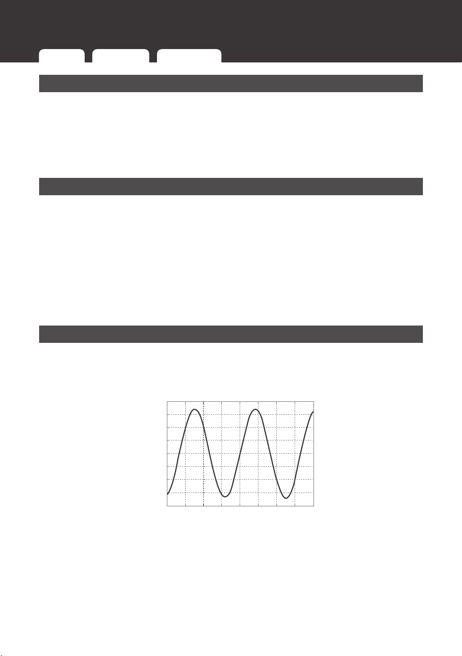
Pure Sine Wave
The Renogy PGH1 Series Battery Power Inverter output a pure sine wave similar to the
waveform of the grid power. In a pure sine wave, the voltage rises and falls in a smooth
fashion with very low harmonic distortion and cleaner utility-like power.
Time(Seconds)
Amplitude(Volts)
Pure(Sine Wavefom)
200
150
100
50
0
-50
-100
-150
-200
-0.02 -0.015 0.015-0.01 0.01-0.005 0 0.005
0.02
This gives users stable enough power to operate tools, fans, lights, computers, and other
electronics without any interference. Pure sine wave inverters are in many cases more
efficient, allowing users to use less energy and allow for more device capability. The main
advantage to pure sine wave inverters is that they are used to operate sensitive electronic
devices that require a high quality waveform with little harmonic distortion. Almost any
electronic device could be powered using a pure sine wave inverter.
Introduction
Key Features Pure Sine Wave
Package Contents
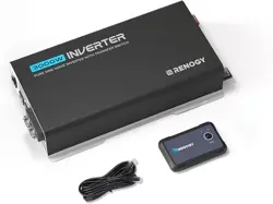
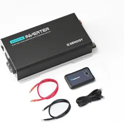
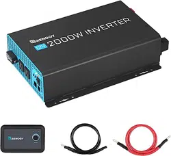
04
Included Components
The inverter will include a wired remote controller that can power the inverter ON or OFF. In
addition, the 1000W and 2000W models will include inverter cables.
Inverter Model Gauge
1000W Inverter (PGH1-10111S) 4 AWG
2000W Inverter (PGH1-20111S) 4 AWG * 2
3000W Inverter (PGH1-30111S) Cables not included. 4/0 Recommended
Wired Remote Control
The Wired Remote Control for the inverter gives users the
opportunity to power on/off the inverter from a distance.
Giving you approximately 16.4ft of distance, simply connect
the cable to the REMOTE port on the PGH inverter. Make
sure the inverter switch is flipped to REM and the wired
remote power button is unpressed. When connected, press
the wired remote's power button to turn on the inverter.
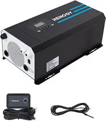
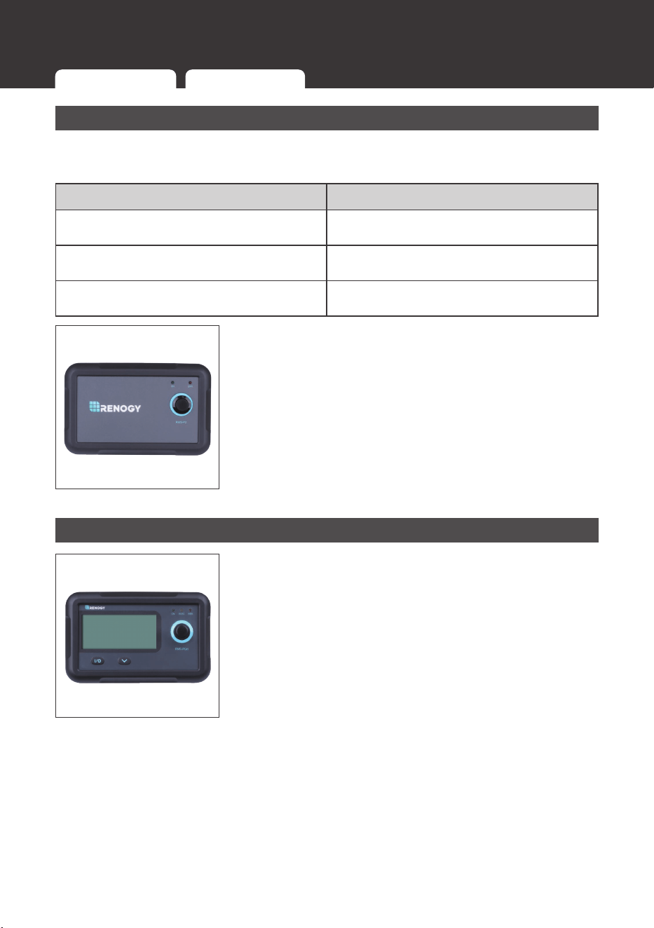
Optional Components
Monitoring Screen (Model: RMS-PGH)
The RMS-PGH is a high precision meter designed for the
PGH1 Power Saving Inverter Series. Utilize the 2-key input
to easily navigate through your system information as well
as identify any error codes. You can also use the main push
button to power your inverter on/off at your convenience. The
RMS-PGH is the perfect monitor companion to optimize any
solar-inverter system!
Package Contents
Included Components Optional Components
Product Overview
05
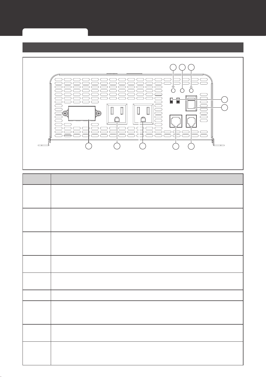
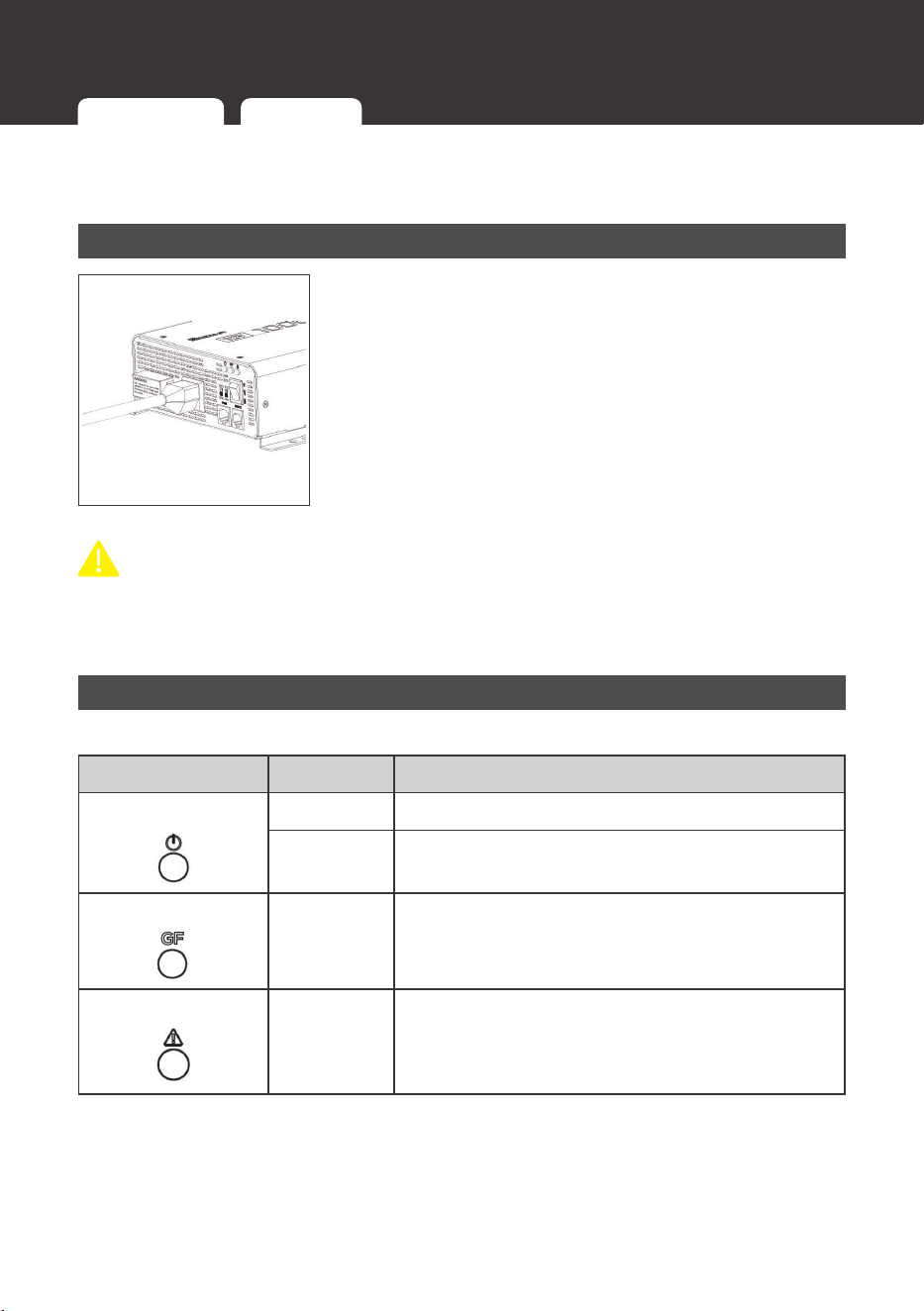
Identification of Parts (AC Side)
Figure 1: 2000W Inverter
AC OUTPUT AC OUTPUT
L N G
ON
OFF
REM.
REMOTE
ECO
GF
COMM.
50Hz
60Hz Nor.
5
4
1 2 3
9 88
7 6
No. Part
1
Power LED (Green): Solid Green indicates normal power on operation.
Flashing Green indicates inverter is powered in ECO power saving mode and
is pulsing.
2
GF LED (Yellow): Indicates an interruption in the circuit. Shut down the
inverter to clear or review AC wiring. The inverter does not have Neutral and
Ground bonded. Refer to Troubleshooting.
3
Fault LED (Red) + Alarm: Solid Red light indicates a system fault due to
either overheating, overload, undervoltage, or over-voltage. Alarm sounding is
typical for a low battery voltage. Refer to Troubleshooting.
4
DIP Switches (Frequency/Power Saver): Adjust the frequency or ECO power
saver mode.
5
ON/OFF/REM Power Button: Main power button that can switch between
ON, Off, or be in Remote control mode.
6 Remote Port: Connect the included wired remote onto this port.
7
Communication Port (RS485): Optional port for connecting the BT-2 Module
(Model: RCM-BT2) or Monitoring Screen (Model: RMS-PGH). Requires
separate purchase.
8
AC Outlets: Directly plug in AC appliances. Utilize up to 8.3Amps (1000W) or
up to 15amps (2000W/3000W).
9
AC Terminal Block (Covered): Use the terminal block to utilize the full
wattage in 110V AC 50Hz / 60Hz for the 2000W / 3000W models. 1000W
model can use full wattage using the AC outlets.
Product Overview
Identification of Parts (AC Side) Identification of Parts (DC Side)
Product Overview
06
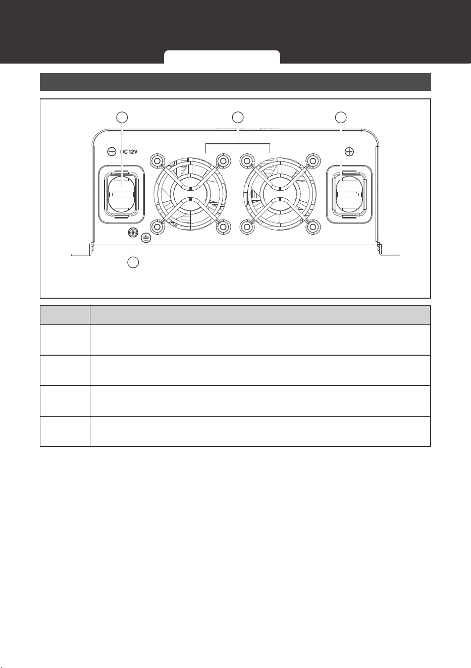
Identification of Parts (DC Side)
4
Figure 1: 2000W Inverter
3
2
1
No. Part
1
12VDC M8 Negative Battery Terminal: Negative 12V DC is written above the
terminal.
2
Ventilation Fans: Automatic fans that dissipate heat inside the inverter. They
that are temperature controlled.
3
12VDC M8 Positive Battery Terminal: Positive 12V DC is written above the
terminal.
4
M4 Grounding Lug: Connect to grounding point which will vary depending on
install.
Identification of Parts (AC Side) Identification of Parts (DC Side)

Installation
07
WARNING
z
Make sure inverter is in the off position before connecting anything.
CAUTION
z
Do not over tighten the terminals. This could potentially damage the inverter.
Location Recommendations
WARNING
z
Never install the inverter in a sealed enclosure with flooded batteries. Gas can
accumulate and there is a risk of explosion.
Ensure installation follows the following guidelines:
1. Cool, dry, well-ventilated area:
Heat is the worst enemy for electronic equipment.
Inverters must be in an area where the fans are not blocked or where they are not hit
directly by the sun. They should be in an area free of any kind of moisture and allow for
clearance of at least 10” around the inverter to provide for adequate ventilation.
2. Protection against fire hazard: the inverter should be away from any flammable
material, liquids, or any other combustible material. The inverter can spark and the
consequences could be severe.
3. Close proximity to battery bank: prevent excessive voltage drop by keeping the
inverter close to the battery bank and having a properly sized wire going from the battery
bank to the inverter.
4. Limiting electromagnetic interference (EMI): ensure the inverter is firmly grounded to
a building, vehicle, or earth grounded. Keep the inverter away from EMI receptors such
as TVs, radios, and other audio/visual electronics to prevent damage / interference to the
equipment.
5. Secure mounting: The inverter should be standalone or mounted by using the outlying
terminals with M6 or M8 screws on the inverter.
WARNING
z
The inverter should be mounted to a solid horizontal base. Vertical installations need to
ensure clearance of fans for proper cooling. Never mount the inverter upside down due
to lack of heat dissipation.
Installation
Location Recommendations Sizing your Battery Bank

Installation
08
Sizing your Battery Bank
Battery types and capacity relate to overall inverter performance. To size a battery bank, you
need to identify the loads that you will be utilizing, as well as an estimate (hours/day) you
will be using the load. The inverter is only compatible with 12V battery banks and oversizing
should be considered due to efficiency losses.
1. Determine your Watts (Amps * Volts): every electronic will have a sticker or plate
identifying the watts directly (W) or will show you the voltage value (V) as well as
amperage (A) which need to be multiplied to get Watts. The formula is below:
Watts (W) = Volts (V) * Amps (A)
Fan Watts = 120V * 0.4A = 48Watts
2. Estimate Load Run: Time in Watt-Hours (Wh)—Estimate how many hours per day you
will be using the load and multiply this by your Watts per load.
Fan Watts * 12 hours = Watt-Hour (Wh)
46W * 12h = 576Wh
3. Determine Battery Capacity in Amp-Hour (Ah): Divide your Load Run Watt-Hour result
by the battery voltage. This inverter is 12V, so we will use this as the reference:
Load Run-Time (Wh) / Battery Voltage (V) = Amp-Hour (Ah)
576Wh / 12V = 48 Ah
4. Oversize the Battery: The calculated Amp-Hour value represents the minimum size
battery capacity to run your load for your intended time. Note that this assumes 100%
use of a battery, which is not recommended. Assuming 50% depth of discharge (DoD),
you want to divide by this value and then multiply by a factor of 1.25 to account for some
efficiency losses.
NOTE
z
You will need a battery charging source as this is a non-charging inverter and will only
work to deplete the battery.
(Amp-Hour / DoD
%
) * Efficiency Losses = Recommended Amp-Hour
(48Ah / 50% DoD) * 1.2 = Approx. 115Ah
A 115Ah battery bank, or close, will be able to support a 12-hour run time while also
prolonging battery life for the best system size possible.
NOTE
z
This is an example and actual quantities vary by battery capacity and rates of discharge.
Location Recommendations Sizing your Battery Bank
Wiring
09
Wiring
Grounding
If available, the chassis ground lug should be connected to a ground point such as a vehicle
chassis or boat grounding system. In fixed locations, connect the ground lug to earth ground.
The connections to ground must be tight and against bare metal. Whether using the inverter
in a mobile application, such as an RV, or in a building, grounding is highly recommended.
The recommended wire size for grounding is 14AWG (1000W), 12AWG (2000W), and 10
AWG (3000W) insulated copper strand wire.
The neutral (common) is not bonded to the chassis ground. Therefore, when chassis is
connected to ground, the neutral conductor is not grounded. At no point should the chassis
ground and the neutral conductor of the inverter be bonded. Bonding the chassis ground and
the neutral conductor of the inverter or connecting the inverter to household AC distribution
wiring will damage the inverter and void the warranty. For more information regarding
grounding, users and/or installers must consult with the Local and National Electric Codes
(NEC) for more specific grounding regulations and suggestions as they can change per
scenario.
WARNING
z
At no point should the chassis ground and the neutral conductor of the inverter be
bonded. Bonding the chassis ground and the neutral conductor of the inverter or
connecting the inverter to household or recreational AC distribution wiring will damage
the inverter and void the warranty.
CAUTION
z
Do not over-tighten the M4 Ground Screw. The recommended torque is 1.5~2.0N-m /
13~18.2 lbf-in.
DC Wiring
WARNING
z
The Renogy Pure Sine Wave Inverters are suitable for 12V battery bank systems ONLY.
Not following the minimum DC requirement will cause irreversible damage to the inverter.
CAUTION
z
Be careful of the positive and negative poles. Reversing the poles might cause
permanent damage to the inverter. It will surely blow the internal fuse.
NOTE
z
Damage to the Renogy inverters due to reverse polarity is NOT covered by warranty.
The input terminals of the inverters have large capacitors connected to them. Once a
positive and negative wire are connected to the terminals, it will complete the circuit,
and commence drawing a heavy current momentarily. As a result, there may be a
sparking occurring even if the inverter is in the off position. To minimize sparking, it is
recommended that the user have the appropriate size wire feeding into the inverters and/
or install an external fuse leading into the inverter.
Grounding
DC Wiring AC Wiring Fusing
Wiring
10
z
Do not over-tighten the M8 DC Terminals. The recommended torque is 12 ~ 16N-m /
105.9 ~ 141.5 lbf-in.
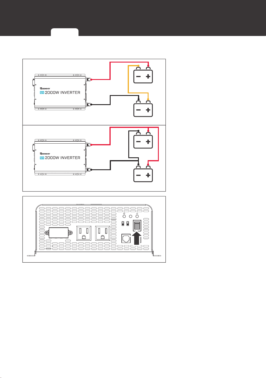
12V: 2 x 6V Series
6V Battery
6V Battery
12V: 2 x 12V Parallel
12V Battery
12V Battery
1. Make sure your battery
bank is rated for 12V.
Batteries that are 6V
may be put in series to
create a 12V battery
bank. 12V batteries may
be connected in parallel
prior to connecting to the
inverter DC terminals.
When joining batteries
together, they must be
the same chemistry,
voltage, and are also
recommended to be
the same level prior to
combining.
AC OUTPUT AC OUTPUT
L N G
ON
OFF
REM.
REMOTE
ECO
GF
COMM.
50Hz
60Hz Nor.
2. Flip inverter power to
OFF position (on AC
side).
Grounding
DC Wiring AC Wiring Fusing
Wiring
11
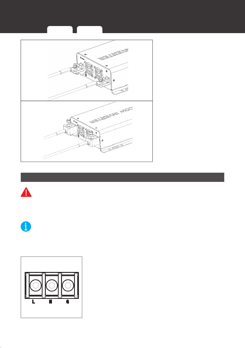
3. Remove Cap, then
unscrew inverter
terminals and connect
battery connections.
Then tighten.
AC Wiring
WARNING
z
All AC Wiring should be approved by an electrician for RV or Marine applications. Do
not connect the AC Output to a power source like a generator/shore power. Irreversible
damage may occur. to the inverter.
NOTE
z
Do not over-tighten the screws in the AC Terminal Cover or Terminal Block. The
recommended torque for the M3 terminal cover screws is .64 ~ 1.0N-m / 5.7 ~ 9.1 lbf-in.
z
The recommended torque for the M4 terminal block is Max 0.98N-m / 8.7 lbf-in.
You can plug your AC loads directly into the receptacles on
the inverter
’
s AC Side. You can also hardwire (permanently
connect) the AC output from the AC hardwire terminal
through the AC knockout into a load sub-panel or additional
AC outlets powered by the inverter. From left to right, the
terminal block indicates: Live/Hot (L), Neutral (N), and
Ground (G).
Grounding
DC Wiring AC Wiring Fusing
Wiring
12
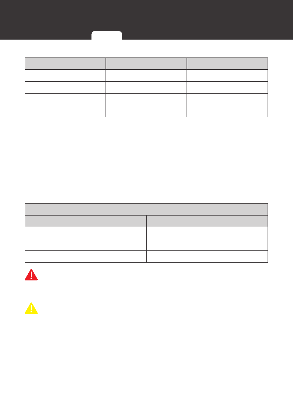
▇
Typical Colors for AC Wiring
Live Neutral Ground
Red White Green
Black Light Grey Bare
Brown - -
Blue - -
▇
Recommended Ground-Fault Circuit Interrupter (GFCI)
A ground-fault circuit interrupter, or GFCI, is a device that help protect people from electric
shocks by de-energizing a circuit or portion of a circuit within an established period of time
when a current to ground exceeds some predetermined value that is less than that required
to operate the overcurrent device (circuit breaker or fuse) of the supply circuit. GFCIs are
usually required in wet or damp locations.
While the inverter is equipped with a GFCI, it is recommended to install an external GFCI
where you can manually test the circuit.
The following table lists GFCIs that meet the specifications and will function properly when
they are connected to the AC Outlets of the inverter.
Tested GFCI Models
Manufacturer Model Number
Leviton GFNT2
Hubbell GFRST20
Hubbell GF15WLA
WARNING
z
Risk of electrical shock. Use only ground-fault circuit interrupters [receptacle(s) or circuit
breaker(s)] compatible with your PGH1 inverter.
CAUTION
z
GFCIs shall be installed in a recreational
vehicle’s
wiring system to protect all branch
circuits.
Grounding
DC Wiring AC Wiring Fusing
Wiring
13
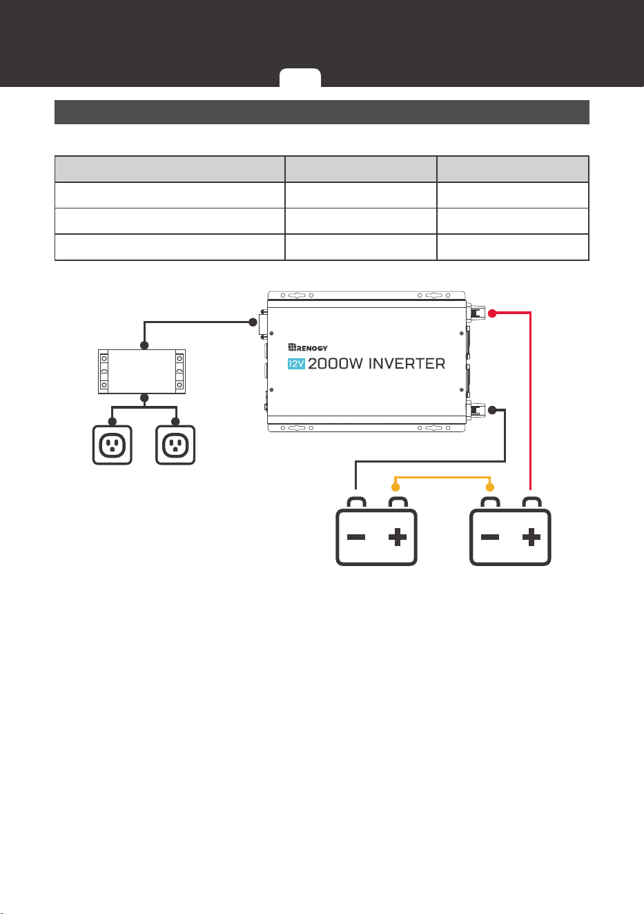
Fusing
The following are recommended fuse minimums:
Model Fuse Minimum AWG Minimum
1000W Inverter (PGH1-10111S) 100A 4 AWG
2000W Inverter (PGH1-20111S) 200A 2 AWG
3000W Inverter (PGH1-30111S) 300A 4/0 AWG
6V Battery 6V Battery
Sub Panel
Grounding
DC Wiring AC Wiring Fusing
Operation
14
Assuming proper connection, the inverter is now ready for use. To operate using the AC
Outlets:
AC Side Operation
1. Connect electronic devices to electrical socket(s) on
inverter. Flip inverter power to ON position (on AC side).
2. When finished, switch AC devices off FIRST, then turn off
inverter switch.
3. Turn the device
’
s power switch on to begin normal use.
4. To power down, turn off the device first then proceed to
shut down the inverter.
CAUTION
z
Avoid connecting powered on Devices before connecting to the inverter. Devices in the
ON position may trigger an overload as they might have a high initial startup power when
first connecting to the inverter.
LED Overview
The inverter has 3 LEDs that dictate different events: Power, Ground fault, and Fault.
LED Behavior Meaning
Power (Green) Solid The inverter is powered on (normal mode).
Slow Flash
Eco power saving mode. The inverter will pulse to
detect any AC loads above 50W.
GF (Yellow)
Solid
Ground fault detection of an unintentional electric
path diverting current to ground.
Fault (Red) + Alarm
Solid
Inverter Overheating
Inverter Overload
Inverter Undervoltage
Inverter Overvoltage
Operation
AC Side Operation LED Overview Wired Remote DIP Switches
Operation
15
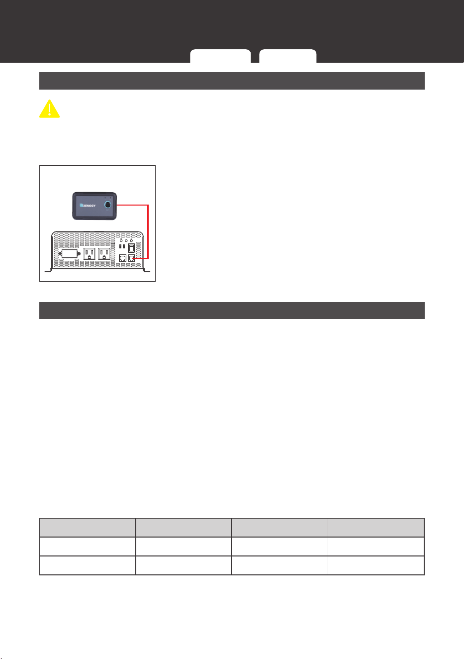
Wired Remote
CAUTION
z
The wired remote will only operate when REM mode is pressed on the inverter.
The wired remote control is an alternative way to power on or off your inverter from a
distance. To operate:
AC OUTPUT AC OUTPUT
L N G
ON
OFF
REM.
REMOTE
ECO
GF
COMM.
50Hz
60Hz Nor.
1. Make sure the push button on the wired remote is not
pressed.
2. Flip the inverter switch to REM mode.
3. Connect the remote wire to the REMOTE port on the
inverter model.
4. To confirm success, press the power button to power on
the inverter via remote.
DIP Switches
The DIP switches allow you to control the inverter
’
s ac output frequency or power up in an
ECO power saving mode. For DIP switch changes to take effect you must:
1. Shut down the inverter via power button or remote.
2. Make the desired dip switch change.
3. Power On the inverter via power button or remote.
4. DIP Switch changes have taken effect.
▇
Frequency DIP Switch
You can change your AC output frequency between 50Hz or 60Hz depending on your
location. By default, the USA uses 60Hz.
▇
ECO Mode
ECO mode is a battery saver mode. When on, the inverter will search for a load by sending
a pulse every 2~3 seconds to the AC outlets. The Power LED will also pulse. Loads that are
50Watts or less will not be powered on and the inverter will remain in this mode until 50W or
greater is detected or until it is manually shutdown.
Power Mode Power LED AC Load ≤ 50W AC Load > 50W
Normal Solid Power On Power On
ECO Pulsing Idle Power On
AC Side Operation LED Overview Wired Remote DIP Switches

Troubleshooting
16
Troubleshooting
Indicator Potential Issue Troubleshoot
Fault LED Lit
and Alarm
Beeps
Battery
Undervoltage
Alarm
The battery is depleting faster than it is being charged.
Lower the inverter load power or disconnect the load to
let the battery charge up to 12.0V at least.
Battery
Overvoltage
Alarm
The battery is at a higher than normal voltage, perhaps
from being charged. Use a multi-meter to confirm the
voltage and disconnect any chargers.
Fault LED
Lit, Inverter
shutdown,
alarm on
Input Voltage
has reached
the low voltage
disconnect and
shut down the
inverter
Disconnect any loads and use a charging source to
charge the battery bank back up to an appropriate
voltage of at least 12.0V.
Input Voltage
has reached
the high voltage
disconnect and
shut down the
inverter
Double check the charger is rated for the battery type.
Use a multi-meter to check for the source of the high
voltage and disconnect any chargers.
Inverter High
Temperature
Allow the inverter to cool down by disconnecting any
loads or by physically moving the inverter to a cooler
location. Check for adequate ventilation.
Load Output
exceeds
inverter rating
Double check the appliance and make sure the watts
(volts X amps) are within the specified rating of the
inverter. In addition, make sure your batteries are fully
charged as a low charged battery and a high load will
also fault.
Inverter
experiencing a
short circuit
Shut down the inverter, disconnect all connections and
reconnect again.

Troubleshooting
17
Indicator Potential Issue Troubleshoot
Yellow GFCI
Indicator Lit
Problem with
the AC outlets
The GFCI equipment is sensitive and could trip when
other GFCIs are present. Make sure there are none, or
that they do not interfere in the same circuit. Keep your
AC output connected directly to a load or extension
cord and avoid complicated connections when utilizing
the AC Outlet. Utilize the AC terminal block for making
AC connections and minimize any GFCI error.
GFCI issue with
electrical panel
GFCI can trip when wiring up to an electrical panel.
An electrical panel and/or the AC wiring can cause the
GFCI to detect a discrepancy between line and neutral,
as if there was a ground leak. Standard GFCIs tend
to trip when other GFCI outlets are present. Utilize the
AC terminal block as the alternative in your application.
More complex solutions might require Double checking
your AC output connection and verifying correct
paths between the neutral, and ground and should be
checked by a qualified electrician.
Technical Specifications
18
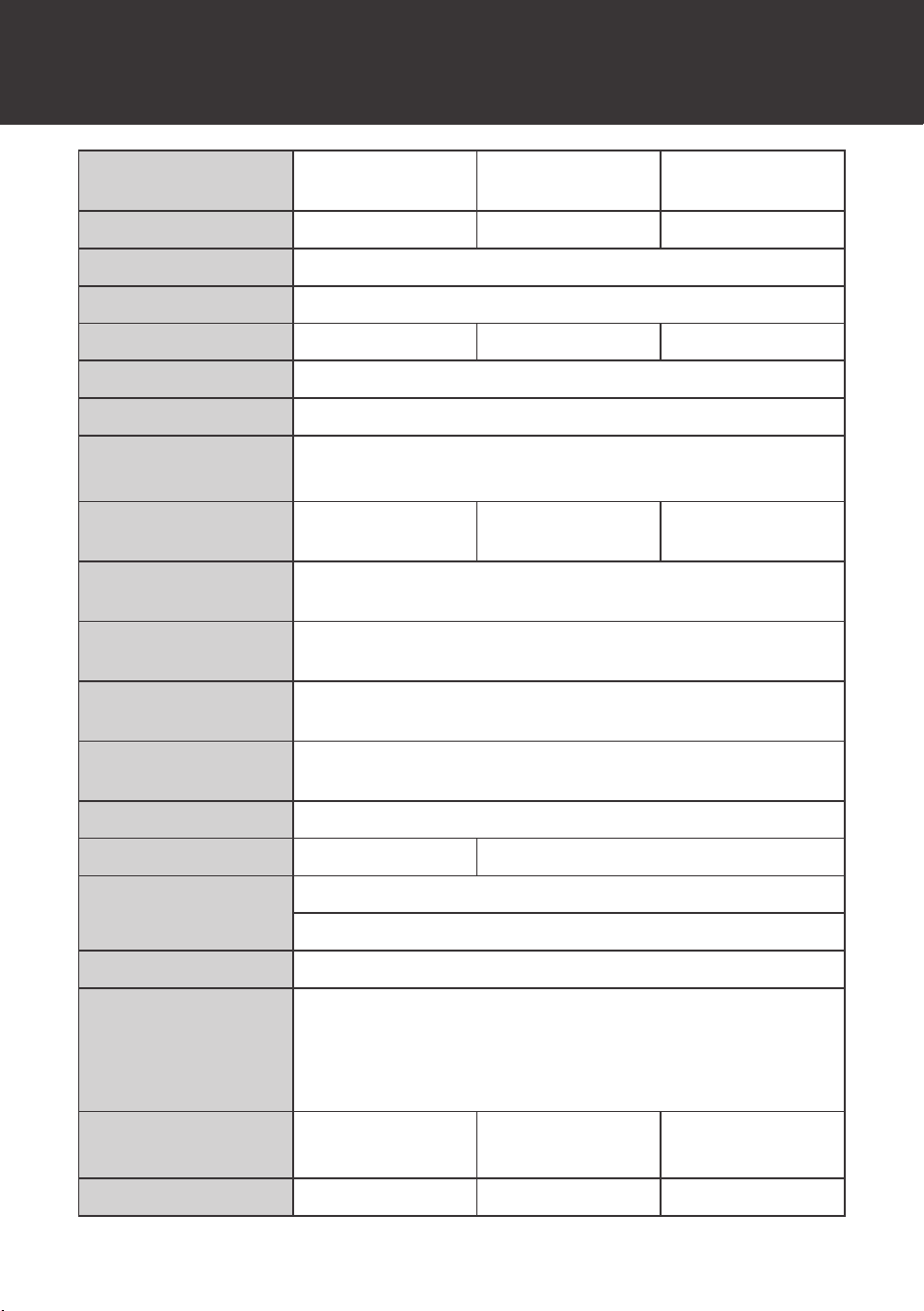
Technical Specifications
Model
1000W Inverter
(PGH1-10111S)
2000W Inverter
(PGH1-20111S)
3000W Inverter
(PGH1-30111S)
Continuous Power 1000W 2000W 3000W
Input Voltage 12V DC
Output Voltage
120V (±10%) AC
Peak Surge 2000W 4000W 6000W
Efficiency >90%
Frequency 50Hz / 60Hz (adjustable)
Total Harmonic
Distortion
Linear Load: <3%
Non-linear Load: <5%
No Load
Consumption
<1A <2A <3A
High Voltage
Disconnect
16V
(±0.3V)
DC
Battery Under-voltage
Alarm
11V
(±0.3V)
DC
Low Voltage
Shutdown
10.5V
(±0.3V)
DC
Normal Operating
Voltage
11V ~ 15V DC
Cooling Thermally controlled fans
AC Sockets 1 2
Temperature Range
Operating Temperature
:
-4°F
~
104°F / -20°C
~
40°C
Storage Temperature
:
-40°F
~
158°F /
-
40°C
~
70°C
Power Output Control
Inverter Power Switch, Remote
Terminals (D-P x L)
AC Terminal Cover: M3-0.5 x 8
AC Terminal Block: M4-0.7 x 10
DC Terminals: M8-1.25 x 15
Grounding Screw: M4-0.7 x 12
Dimensions
13.4 x 7.6 x 2.8in
340 x 193 x 71mm
15.8 x 9.8 x 3.8in
401 x 249 x 96mm
18.6 x 9.78 x 3.78in
472 x 248 x 96mm
Weight 7.5 lbs / 3.4 kg 10.4 lbs / 4.7 kg 13.4 lbs / 6.1 kg

Technical Specifications
19
Wired Remote Control
List dimensions
2.8 x 4.3 x 1.3 in / 70 x 110 x 31.8 mm
Wire length 16.4 ft
Dimensions
20
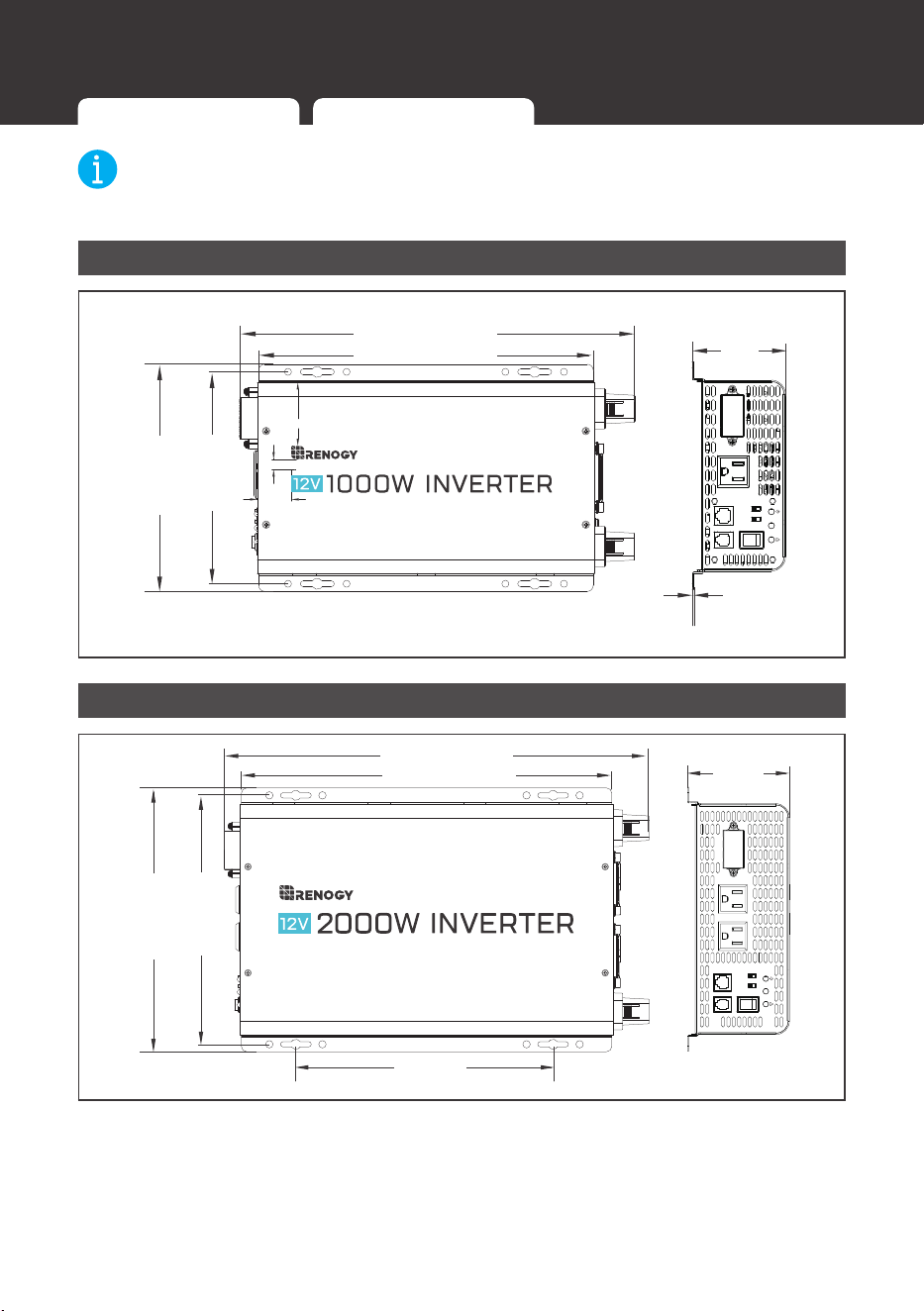
NOTE
z
Dimension tolerance: ±0.2 in (0.5 mm)
1000W Inverter (PGH1-10111S)
290.0mm
[13.4in]
[11.4in]
71.0mm
[2.8in]
1.5mm
[0.1in]
193.0mm
[7.6in]
166.0mm
[6.5in]
29,3
54,2
8,9
AC OUTPUT
L N G
ON OFF REM.
REMOTE
ECO
GF
COMM.
50Hz
60Hz Nor.
340.0mm
2000W Inverter (PGH1-20111S)
249.0mm
234.5mm
96.0mm
[3.8in]
242.3mm
[9.5in]
[9.2in]
[9.8in]
AC OUTPUT AC OUTPUT
L
N
G
ON
OFF
REM.
REMOTE
ECO
GF
COMM.
50Hz
60Hz Nor.
351.5mm
[15.8in]
[12.4in]
401.0mm
Dimensions
1000W Inverter (PGH1-10111S) 2000W Inverter (PGH1-20111S) 3000W Inverter (PGH1-30111S)
Dimensions
21
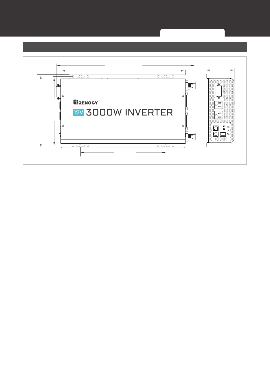
3000W Inverter (PGH1-30111S)
AC OUTPUT AC OUTPUT
L N G
ON
OFF
REM.
REMOTE
ECO
GF
COMM.
50Hz
60Hz Nor.
423.5mm
[18.6in]
[16.7in]
472.5mm
290.3mm
[11.4in]
96.0mm
[3.8in]
249.0mm
234.5mm
[9.2in]
[9.8in]
1000W Inverter (PGH1-10111S) 2000W Inverter (PGH1-20111S) 3000W Inverter (PGH1-30111S)

Maintenance
22
Inspection
For optimum performance, it is recommended to perform these tasks regularly.
z
Ensure the inverter is installed in a clean, dry and ventilated area.
z
Ensure there is no damage or wear on the cables.
z
Ensure the firmness of the connectors and check if there are any loose, damaged or
burnt connections.
z
Make sure the indicators are in proper condition.
z
Ensure there is no corrosion, insulation damage, or discoloration marks of overheating or
burning.
z
If the inverter is dirty, use a damp cloth to clean the outside of the device to prevent dust
and dirt from accumulating. Before the inverter is powered on, make sure it is completely
dry after cleaning.
z
Make sure the ventilation holes are not blocked.
WARNING
z
Risk of electric shock! Make sure that all power supplies are turned off before touching
terminals on the inverter.
Cleaning
Follow the steps below to clean the inverter regularly.
z
Disconnect all cables connected to the inverter.
z
Wear proper protective equipment and use insulated tools during operation. Be careful
when touching bare terminals of capacitors as they may retain high lethal voltages even
after power is removed.
z
Wipe the housing of the inverter and connector contacts with a dry cloth or nonmetallic
brush. If it is still dirty, you can use household cleaners.
z
Make sure the ventilation holes are not blocked.
z
Dry the inverter with a clean cloth and keep the area around the inverter clean and dry.
z
Make sure the inverter charger is completely dry before reconnecting it to the battery and
AC output.
Storage
Follow the tips below to ensure that the inverter is stored well.
z
Disconnect all cables connected to the inverter.
z
By applying dielectric grease to each connector contact, the dielectric grease repels
moisture and protects the connector contacts from corrosion.
z
Store the inverter in a well-ventilated, dry, and clean environment with the temperature
between -40°F to 158°F or
-
40°C to 70°C.
Maintenance
Inspection
Cleaning Storage
Emergency Responses
23
In the event of any threat to health or safety, always begin with the steps below before
addressing other suggestions.
z
Immediately contact the fire department or other relevant emergency response team.
z
Notify all people who might be affected and ensure that they can evacuate the area.
WARNING
z
Only perform the suggested actions below if it is safe to do so.
Fire
1. Disconnect all cables connected to the inverter.
2. Put out the fire with a fire extinguisher. Acceptable fire extinguishers include water, CO
2
,
and ABC.
WARNING
z
Do not use type D (flammable metal) fire extinguishers.
Flooding
1. If the inverter is submerged in water, stay away from the water.
2. Disconnect all cables connected to the inverter.
Smell
1. Ventilate the room.
2. Disconnect all cables connected to the inverter.
3. Ensure that nothing is in contact with the inverter.
Noise
1. Disconnect all cables connected to the inverter.
2. Make sure no foreign objects are stuck in the fan of the inverter or the ring terminal.
Emergency Responses
Fire
Flooding
Smell Noise
Technical Support
24
Technical Support
For additional support, contact the Renogy technical support team through renogy.com/
contact-us. Have the following information available when contacting Renogy.
z
Owner name
z
Contact information
z
Order number
z
Purchase channel
z
Serial number
z
Brief description of the issue
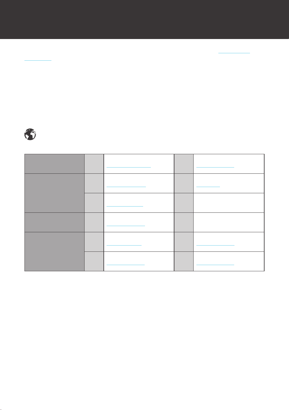
Renogy offers premium services worldwide:
North America
US
www.renogy.com
CA
ca.renogy.com
Asia
CN
www.renogy.cn
JP
renogy.jp
KR
kr.renogy.com
Oceania
AU
au.renogy.com
Europe
FR
fr.renogy.com
DE
de.renogy.com
ES
es.renogy.com
UK
uk.renogy.com
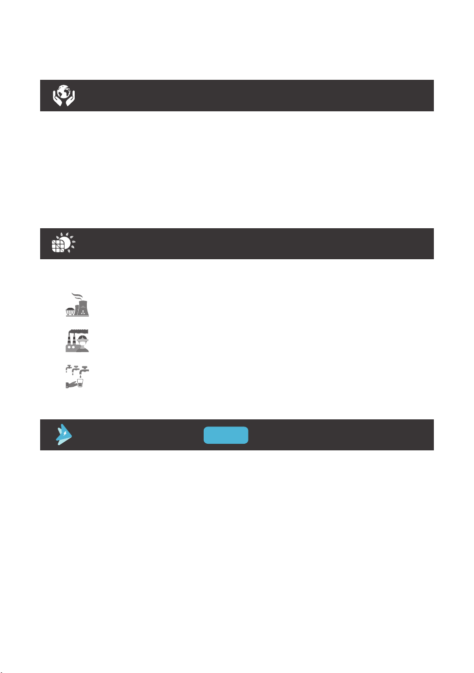
Renogy Empowered
Renogy aims to empower people around the world through education and distribution of
DIYfriendly renewable energy solutions.
We intend to be a driving force for sustainable living and energy independence.
In support of this effort, our range of solar products makes it possible for you to minimize your
carbon footprint by reducing the need for grid power.
Live Sustainably with Renogy
Did you know? In a given month, a 1KW solar energy system will...
Save 170 pounds of coal from being burned
Save 300 pounds of CO
2
from being released into the atmosphere
Save 105 gallons of water from being consumed
PLUS
Renogy Power
Renogy Power Plus allows you to stay in the loop with upcoming solar energy innovations, share
your experiences with your solar energy journey, and connect with like-minded people who are
changing the world in the Renogy Power Plus community.
Also, follow us on Youtube @Renogy Solar, Facebook @Renogy, and Instagram @renogyofficial.