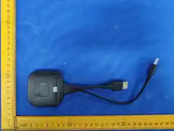
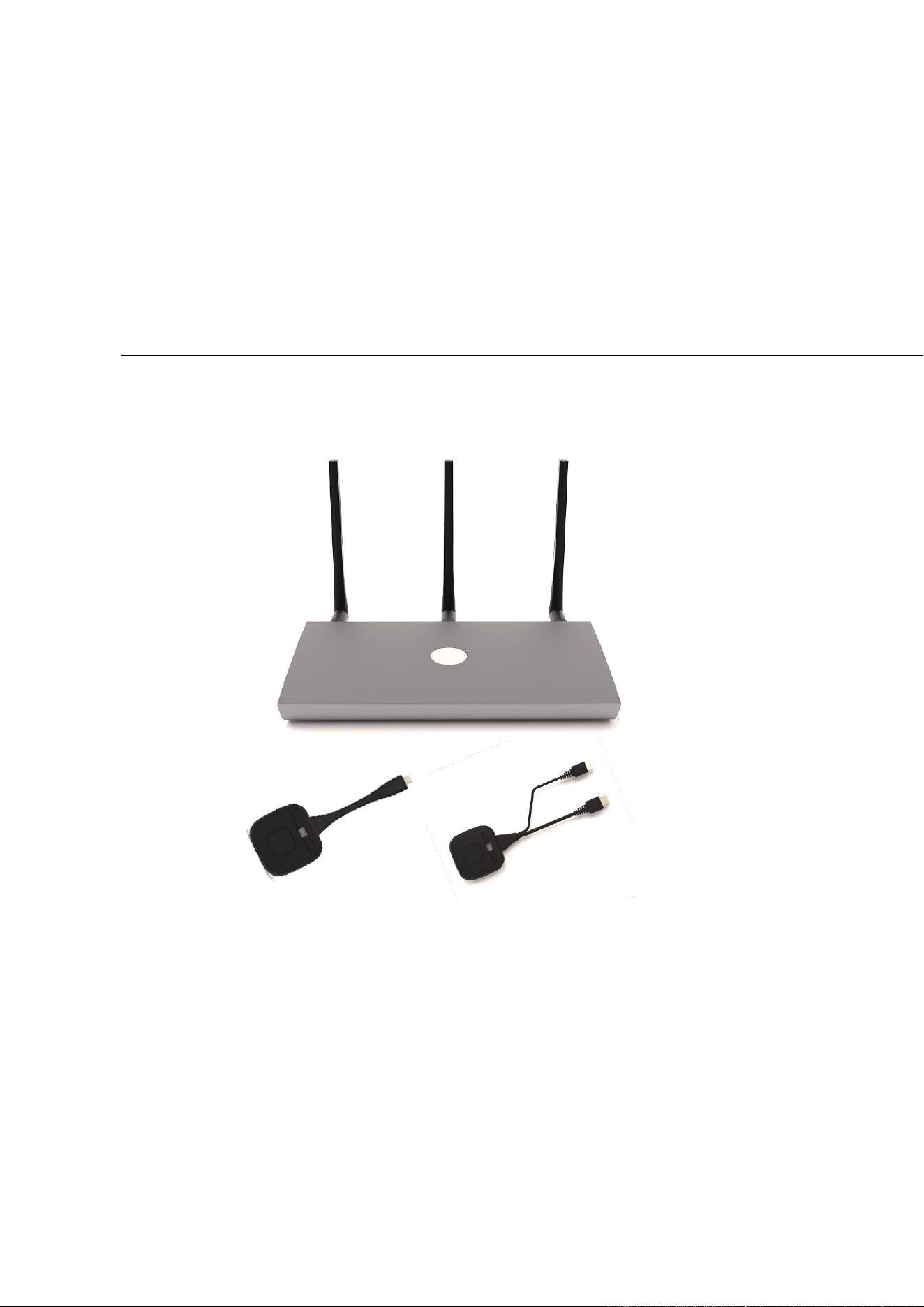
Wireless Conferencing and Presentation Switcher
USER MANUAL
P35&WMT-H55/WMT-C55
SWITCHERS & MATRIXES
EN P35 / WMT-H55 / WMT-C55

2
TABLE
OF
CONTENTS
1.
PRECAUTIONS
...........................................................................................................................
5
1.1
Important
Remark
....................................................................................................................5
1.2
Important
Safety
Instructions
..................................................................................................
6
1.3
Cleaning
....................................................................................................................................6
2.
PACKAGE
CONTENTS
.................................................................................................................
7
3.
DESCRIPTION
and
FEATURES
.....................................................................................................
7
3.1
Main
Features
..........................................................................................................................
7
3.2
Optional
Accessories
................................................................................................................
8
4.
INSTALL
&
CONNECT
.................................................................................................................
9
4.1
Wall
Mount
Install
....................................................................................................................9
4.2
Connection
Diagram
..............................................................................................................
10
4.3
Power
Connection
..................................................................................................................
10
4.4
Video
Connection
...................................................................................................................
11
4.5
Audio
Connection
...................................................................................................................
11
4.6
LAN
Connection
......................................................................................................................
12
4.7
USB
Control
Devices
Connection
............................................................................................
13
4.8
USB
Conferencing
Devices
Connection
...................................................................................14
5.
START-UP
and
OPERATION
......................................................................................................
15
5.1
Home
Screen
..........................................................................................................................
15
5.2
Pairing
WMT-H55
and
WMT-C55
with
base
unit.......................................................................17
5.3
Wireless
Presentation
Mode
..................................................................................................
18
5.3.1
Screen
Sharing
using
WMT-H55
and
WMT-C55
........................................................18
5.3.2
Screen
Sharing
using
WirelessMedia
Desktop
Application
....................................19
5.3.3
Screen
Sharing
using
Airplay
..................................................................................24
5.3.4
Screen
Sharing
using
Miracast
...............................................................................24
5.3.5
Screen
Sharing
using
Android
application
.............................................................
26
5.3.6
Screen
Sharing
using
Chromecast
..........................................................................
27
5.4
Wireless
Conferencing
Mode
.................................................................................................
28
5.4.1
WMMeeting
Driver
Installation
.............................................................................
28
5.4.2
Conference
via
WirelessMedia
application
............................................................30
5.4.3
Conference
via
transmitter
....................................................................................
31
5.4.4
Switch
cameras
during
wireless
meeting
...............................................................32
5.4.5
Screen
sharing
to
remote
.......................................................................................
33
5.5
Moderator
Preview
Window
..................................................................................................34
5.6
Whiteboard
&
Annotation
.....................................................................................................
35
5.6.1
Whiteboard
............................................................................................................
35
5.6.2
Annotation
.............................................................................................................
37
6.
WebGUI
SETTING
MANAGEMENT
&
CONFIGURATION
..............................................................39

3
6.1
Network
Settings
....................................................................................................................40
6.1.1
Network
Wizard
.....................................................................................................
40
6.1.2
Wireless
Network
Configuration
............................................................................
48
6.1.3
Ethernet
Network
Configuration
............................................................................51
6.1.4
Advance
Setting
......................................................................................................51
6.2
Display
&
Audio
......................................................................................................................
52
6.2.1
HDMI
......................................................................................................................
52
6.2.2
Audio
......................................................................................................................
54
6.2.3
Layout
.....................................................................................................................54
6.2.4
Dual-display
............................................................................................................55
6.2.5
Native
Protocol
.......................................................................................................57
6.3
Home
screen
...........................................................................................................................58
6.3.1
Customize
Home
screen
.........................................................................................
58
6.3.2
Digital
signage
........................................................................................................59
6.3.3
Misc
Setting
............................................................................................................60
6.4
Device
Control
........................................................................................................................
62
6.4.1
Telnet
and
serial
.....................................................................................................62
6.4.2
GPI
Definition
.........................................................................................................
63
6.4.3
Button
Definition
....................................................................................................
64
6.4.4
Transmitters
Manage
.............................................................................................64
6.5
UCC-Device
Manager
.............................................................................................................
65
6.5.1
USB
Hub
switching
.................................................................................................
65
6.5.2
USB
Camera
............................................................................................................65
6.5.3
USB
Audio
...............................................................................................................66
6.6
System
settings
......................................................................................................................
67
6.6.1
Date
&
Time
...........................................................................................................
67
6.6.2
Language
................................................................................................................67
6.6.3
Configuration
file
....................................................................................................68
6.6.4
Auto
Standby
..........................................................................................................68
6.6.5
Reboot
....................................................................................................................
69
6.6.6
Factory
reset
...........................................................................................................69
6.7
Security
settings
.....................................................................................................................
70
6.7.1
Security
Level
..........................................................................................................70
6.7.2
Login
Password
......................................................................................................
71
6.8
Firmware
Updates
..................................................................................................................71
6.9
Other
Settings
........................................................................................................................
72
6.9.1
Auto
Create
Launcher
.............................................................................................72
6.9.2
Clear
history
after
meeting
....................................................................................
73
6.9.3
Developer
tools
......................................................................................................
73
6.10
About
Device
........................................................................................................................
74
7.
FIRMWARE
UPDATE
................................................................................................................
75
7.1
Upgrading
Firmware
version
of
P35
......................................................................................
75
7.2
Upgrading
Firmware
version
of
WMT-H55
/
WMT-C55
............................................................77

4
8. PANEL FUNCTIONS and WIRELESS TRANSMITTERS................................................................... 78
8.1 Front Panel............................................................................................................................. 78
8.2 Rear Panel.............................................................................................................................. 79
8.2.1 Factory Reset Using Rear Panel Button ................................................................. 80
8.3 Wireless Transmitters ............................................................................................................ 83
8.3.1 WMT-H2................................................................................................................. 83
8.3.2 WMT-C2................................................................................................................. 83
8.3.3 LED Indicator.......................................................................................................... 84
9. TROUBLESHOOTING................................................................................................................ 85
10. TECHNICAL DATA ...................................................................................................................89
10.1 Technical Specifications
.....................................................................................................89
10.2 Mechanical Diagram ............................................................................................................91
5
1. PRECAUTIONS
1.1 Important Remark
The lightning flash with arrowhead symbol, within an equilateral triangle, is
intended to alert the user to the presence of uninsulated “dangerous voltage”
within the product’s enclosure that may be of sufficient magnitude to constitute a
risk of electric shock to persons.
The exclamation point within an equilateral triangle is intended to alert the user to
the presence of important operating and maintenance (servicing) instructions in the
literature accompanying the appliance.
WARNING (If applicable): The terminals marked with symbol of “ ” may be of sufficient
magnitude to constitute a risk of electric shock. The external wiring connected to the terminals
requires installation by an instructed person or the use of ready-made leads or cords.
WARNING: To prevent fire or shock hazard, do not expose this equipment to rain or moisture.
WARNING: A device with Class I construction shall be connected to a mains socket-outlet with a
protective earthing connection.
WARNING: This product must not be discarded, under any circumstance, as unsorted
urban waste. Take to the nearest electrical and electronic waste treatment centre.
This equipment has been tested and found to comply with the limits for a Class A
digital device, pursuant to part 15 of the FCC Rules.
These limits are designed to provide reasonable protection against harmful interference when the
equipment is operated in a commercial environment. This equipment generates, uses, and can
radiate radio frequency energy and, if not installed and used in accordance with the instruction
manual, may cause harmful interference to radio communications. Operation of this equipment in
a residential area is likely to cause harmful interference in which case the user will be required to
correct the interference at his own expense.

6
1.2 Important Safety Instructions
1. Read these instructions.
2. Keep these instructions.
3. Heed all warnings.
4. Follow all instructions.
5. Do not use this device near water.
6. Clean only with dry cloth.
7. Do not block any ventilation openings.
Please install in accordance with the
manufacturer’s instructions.
8. Do not install near any heat sources
such as radiators, heat registers, stoves,
or other device (including amplifiers)
that produce heat.
9. Do not defeat the safety purpose of the
polarized or grounding type plug. A
polarized plug has two blades with one
wider than the other. A grounding type
plug has two blades and a third
grounding prong. The wide blade or the
third prong are provided for your
safety. If the provided plug does not fit
into your outlet, consult an electrician
for replacement of the obsolete outlet.
10. Please protect the power cord from
being walked on or pinched particularly
at the plugs, convenience receptacles,
and at the point where they exit from
the device.
11. Please kindly check and just only use
attachments/accessories specified by
the manufacturer.
12. Unplug the device during lightening
sorts or when unused for long periods
of time.
13. Please refer all servicing to qualified
personnel. Servicing is required when
the device has been damaged in any
way, such as power supply cord or plug
is damaged, liquid has been spilled or
objects have fallen into the device, the
device has been exposed to rain or
moisture, does not operate normally,
or has been dropped.
14. Disconnecting from the mains: When
switching off the POWER switch, all the
functions and light indicators of the
base unit will be stopped, but fully
disconnecting the device from mains is
done by unplugging the power cable
from the mains input socket. For this
reason, it always shall remain easily
accessible.
15. Equipment is connected to a socket-
outlet with earthing connection by
means of a power cord.
16. The marking information is located at
the bottom of the unit.
17. The device shall not be exposed to
dripping or splashing and that no
objects filled with liquids, such as vases,
shall be placed on device.
1.3 Cleaning
Clean the unit with a soft, dry clean cloth or slightly wet with water and neutral liquid
soap only, then dry it with a clean cloth. Be careful that water never gets into the unit through
any hole. Never use alcohol, benzine, solvents or abrasive substances to clean this unit.
NEEC AUDIO BARCELONA, S.L. accepts no liability for any damage that may be caused to people,
animal, or objects due to failure to comply with the warnings above.

7
Thank you for choosing our device P35
Wireless Conferencing and Presentation Switcher!
We appreciate your trust.
It is VERY IMPORTANT to carefully read this manual and to fully understand its contents
before any connection in order to maximize your use and get the best performance from this
equipment.
To ensure optimal operation of this device, we strongly recommend that its maintenance be
carried out by our authorised Technical Services.
All products are covered by warranty, please refer to the warranty card included with this
product for the period of validity and conditions.
2. PACKAGE CONTENTS
P35.
Antenna (3 units). Not pre-mounted to avoid damages.
3. DESCRIPTION and FEATURES
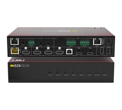
P35 is a wireless conference and presentation switcher with one HDMI input up to 4K30 and two
HDMI outputs. Wireless input supports up to 4K30. It supports sharing PC content to the display
via transmitters, Windows and macOS clients, and native protocols such as Airplay, Miracast, and
Chromecast, while supporting wireless connection of compatible USB devices such as webcams
and microphones via Windows and macOS clients to PC. Supports dual-screen display and can
display 5 devices simultaneously in a multi-view layout. It also has a powerful WebGUI
management background through which all these functions can be configured and managed.
3.1 Main Features
Two channels of HDMI output, supporting up to 4K@60Hz (the other channel is 1080P),
supporting same-screen display or 4+1/1+4 mode display;
One HDMI input, supporting up to 4K@30Hz;
Support EDID management;
2xUSB-A 3.0 +1xUSB-C3.0 + 4xUSB-A 2.0+1xUSB-C 2.0 ports, which can connect two cameras
at the same time (one of which must be connected to the USB-A 2.0 port), used for
switching between long and close shots in video conferencing or Other scenes that require
camera switching;
1XUSB-B 3.0 Device port, the camera connected to the base unit can be switched out
through this port and used by other computers such as Room PC;
2 x USB-A 2.0 touch ports, used to connect the touch screen of the main and sub screens
(please note: the main and sub positions need to be corresponding);

8
Two
Gigabit
network
ports,
one
of
which
supports
POE
power
supply
(802.11at
standard),
supporting
up
to
30W;
3.5
mm
headphone
unbalanced
stereo
analog
audio
output;
One
channel
RS232,
it
supports
receiving
commands
to
control
the
base
unit,
and
also
supports
sending
commands
from
the
base
unit
to
control
other
hosts;
Two
GPI
inputs,
the
maximum
level
supports
5V
input,
and
the
function
of
the
input
port
can
be
customized;
Wireless
input
up
to
4K
30
video
resolution;
Supports
native
wireless
mirroring
protocols
such
as
Airplay,
Chromecast
and
Miracast;
Supports
transmitter
screen
projection
(including
the
latest
4K
dongle
and
the
previous
1080p
dongle);
Continuously
updated
WirelessMedia
computer
client
(currently
supported
by
Windows
11
and
MacOS
14)
supports
screencasting
and
wireless
transmission
of
camera
video
data
to
the
computer;
Powerful
WebGUI
background
management;
Supports
Telnet
to
control
the
base
unit;
More
security
for
encrypted
wireless
transmissions;
Supports
up
to
5
split-screen
displays
and
up
to
16
participants
to
be
projected;
Supports
background
image
customization
for
home
screen;
Supports
wireless
touch
for
interactive
screens,
whiteboard
and
real-time
annotation
tools;
Local
12V
DC
power
supply;
3.2
Optional
Accessories
Wireless
transmitters:
WMT-H55
and
WMT-C55,
used
for
plug
&
play
wireless
mirroringfrom
personal
PC
or
mac
desktop
to
the
main
screen.
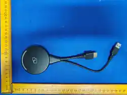
WMT-H55
is
a
HDMI
wireless
transmitter
that
allows
participants
to
easily
share
content
from
a
laptop
or
HDMI
device
to
the
P35
base
unit.
Power
is
supplied
by
an
auxiliary
USB
Type
A
connector.
It
is
designed
as
a
cross
platform
and
plug
and
play
device
with
no
additional
driver
installation
needed.
This
technology
allows
to
start
a
transmission
and
begin
sharing
content
by
just
connecting
the
wireless
transmitter
into
the
source
and
pushing
the
surface.
A
LED
indicator
and
a
vibration
driver,
both
allow
the
user
to
know
the
status
of
the
wireless
transmitter
at
any
time.
WMT-C55
is
an
USB-C
wireless
transmitter
that
allows
participants
to
easily
share
content
from
a
laptop
or
USB-C
video
device
to
the
P35
base
unit.
Power
is
supplied
directly
through
the
same
connector.
It
is
designed
as
a
cross
platform
and
plug
and
play
device
with
no
additional
driver
installation
needed.
This
technology
allows
to
start
a
transmission
and
begin
sharing
content
by
just
connecting
the
wireless
transmitter
into
the
source
and
pushing
the
surface.
A
LED
indicator
and
a
vibration
driver,
both
allow
the
user
to
know
the
status
of
the
wireless
transmitter
at
any
time.
9
4. INSTALL & CONNECT
4.1 Wall Mount Install
The P35 can be installed on the wall or flat surface. At the bottom of P35, there are two mounting
holes that can be fixed to a surface using flat screws.
Mounting screws are not included in the P35 box. The type of screws depends on the type
of wall (stone, wood, plasterboard, ...) you are mounting the Base Unit P35 to. Make sure the
head of the screw is not larger than the hole in the bottom of base unit P35.
For optimal performance, install the P35 close to the display and avoid obstacles between
the P35 and the Transmitters.
Antenna Placement
The antennas should be oriented vertically, so perpendicular to the ceiling and parallel to
the walls.
The antennas should be installed far enough (at least 50cm/1.6ft) from metallic surfaces
to avoid unwanted reflections and far enough (at least 1m/3.3ft) from other radio
equipment that operates in the same frequency range, e.g. other WiFi access points,
cordless telephone, microwave ovens, etc. It is also best to install antennas at least 15
cm (6 inches) from concrete walls.
The most favourable situation is a direct line of sight between antennas and buttons. Any
obstruction will cause the signal to follow a longer propagation path, which can result in
performance degradation.
Due to the particular radio pattern of the dipole antennas, the antennas should not be
placed just above potential positions of P35 users. As a result, the advised position for
the antennas is at the side of the meeting room.
10
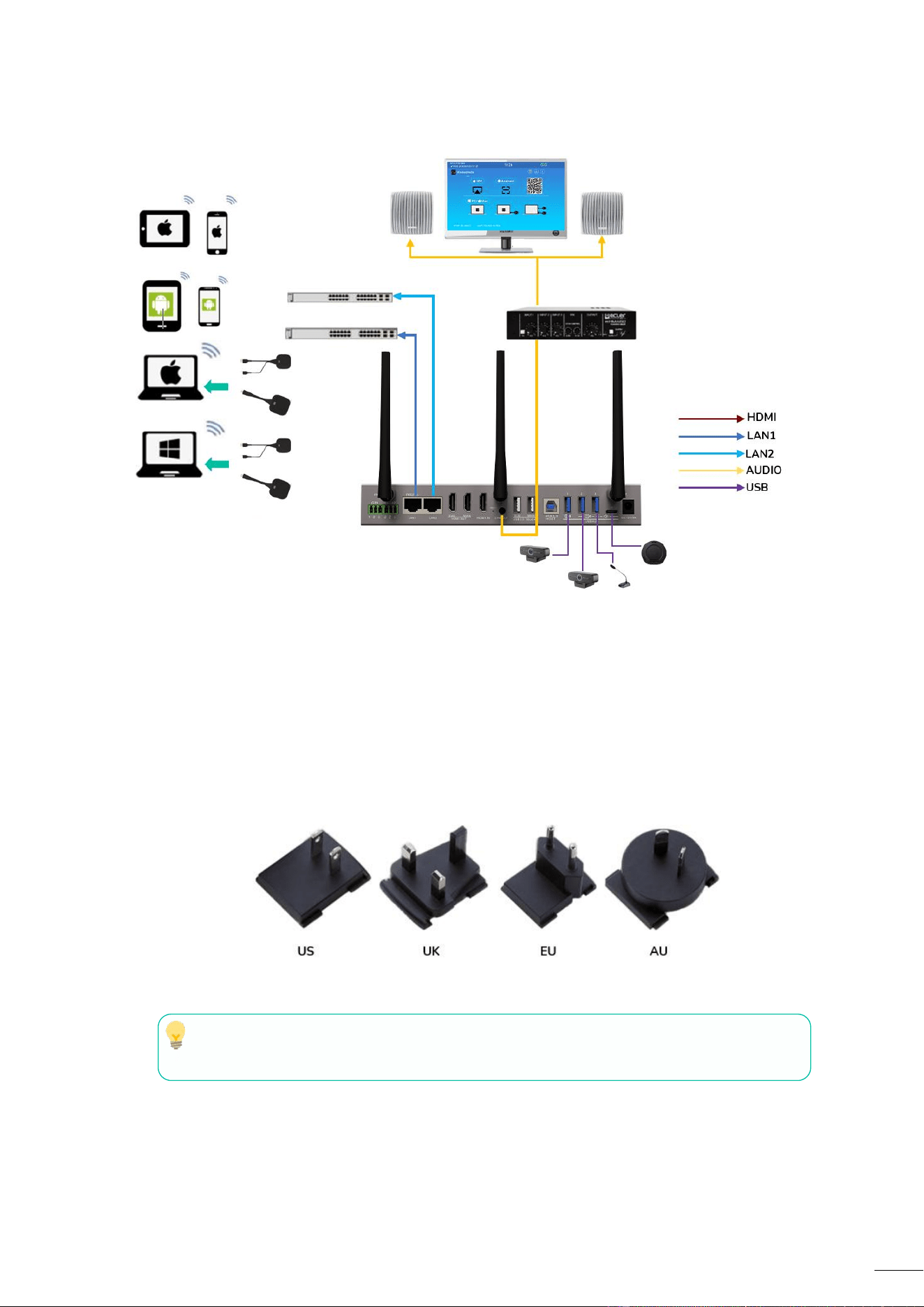
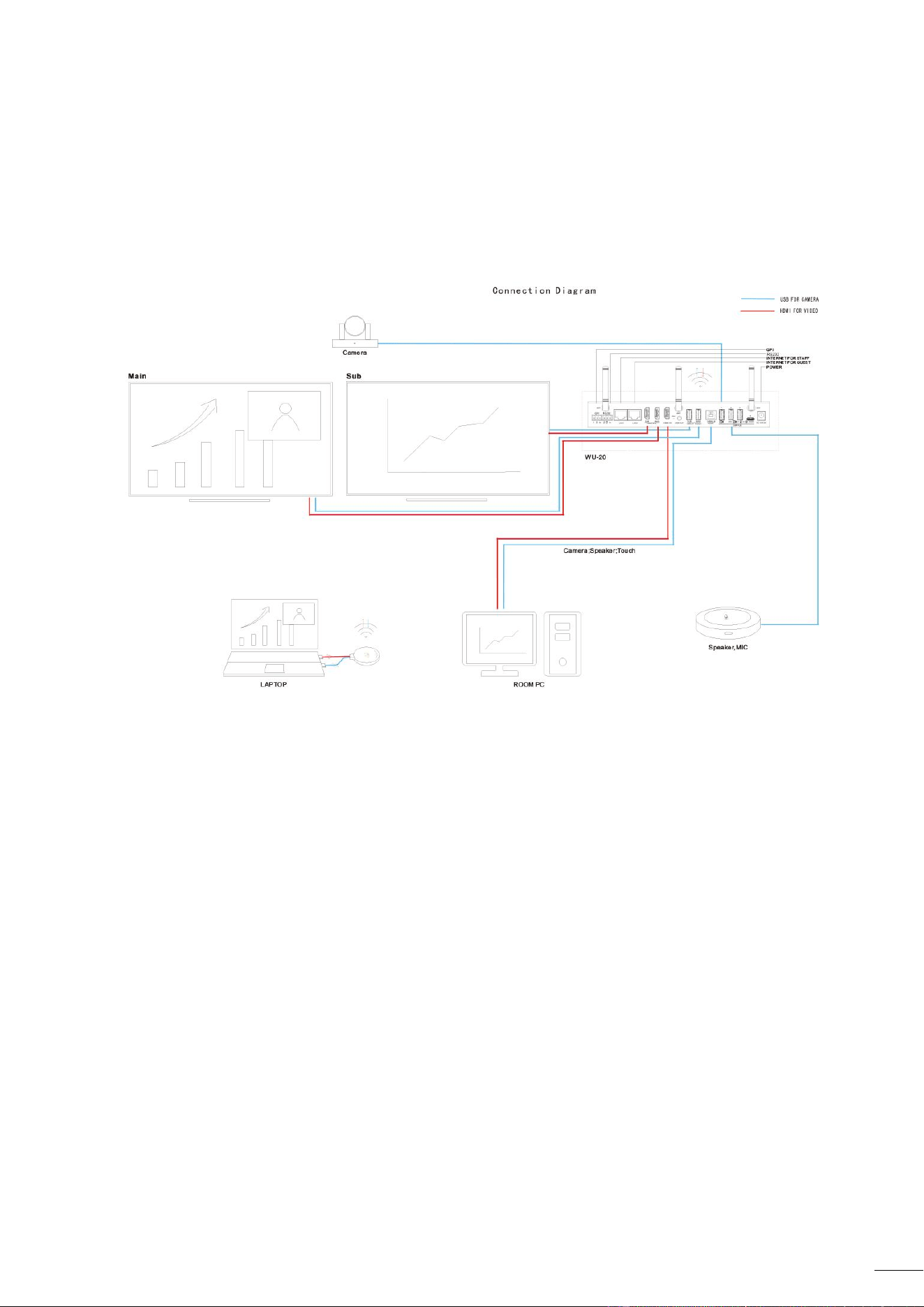
4.2 Connection Diagram
4.3 Power Connection
Local Power Source
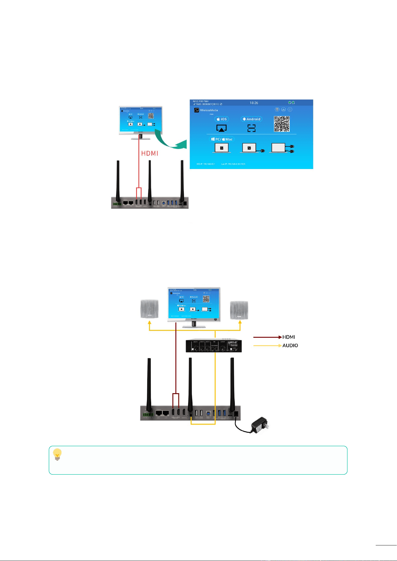
1. Plug the power connector to the power adapter to the power input connector of the
Base Unit P35.
2. Choose the appropriate power plug (US, UK, EU or AU) to be installed on the power
adapter.
3. Connect the power cable plug into the wall outlet.
Once the P35 is powered it is recommended to use the POWER button on the front of
the P35 to switch ON or OFF.
Power over Ethernet
If the LAN Ethernet switcher supports PoE (Power over Ethernet), LAN 1 port can be used to
power up the Base-unit P35 instead of using the external power adapter. (LAN1 Port of the
base unit supports PoE.).
11
4.4 Video Connection
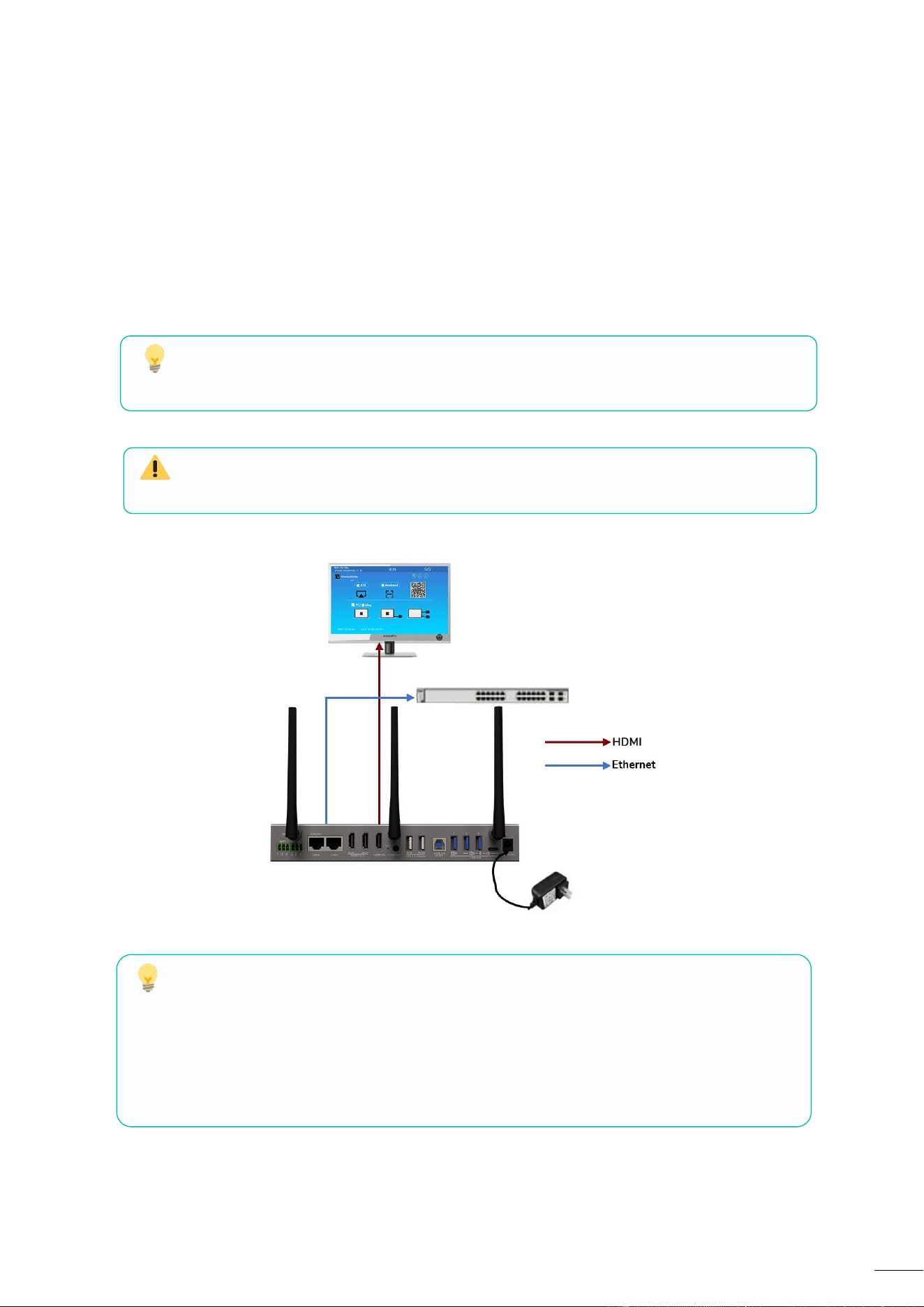
1. Connect the HDMI Output of P35 to a 4K or Full-HD display by a HDMI cable.
2. After starting up, the system displays the home page, as shown below.
4.5 Audio Connection
1. Connect an audio cable with mini jack socket 3.5mm connector into the audio of the P35.
2. Connect the other side to the meeting room’s sound system.
WMT-H55
and
WMT-C55
can
transmit
audio
to
the
P35
base
unit
when
the
audio output
of
the
source
device
is
selected.
12
4.6 LAN Connection
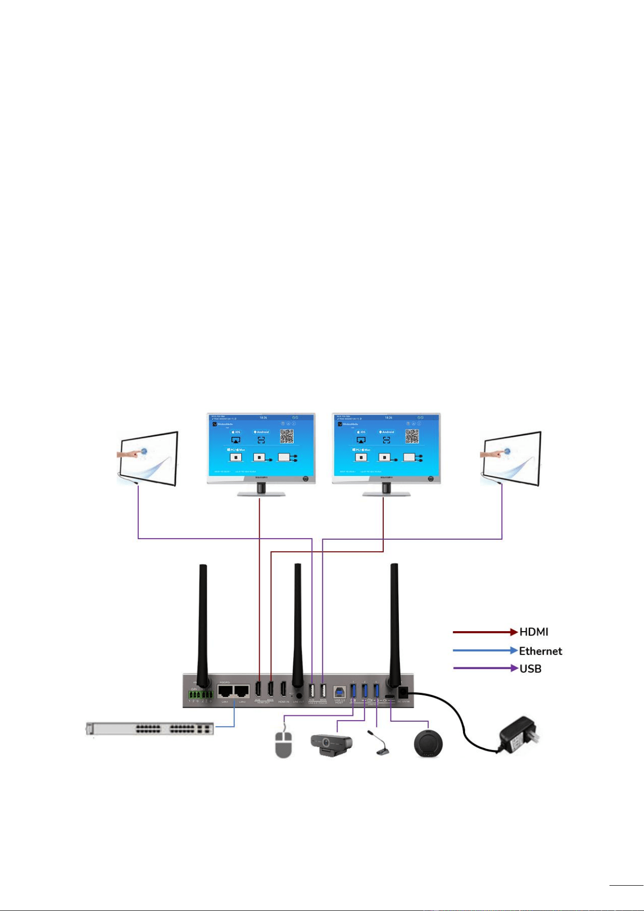
1. Connect a network cable with RJ-45 connector into the LAN 1 or LAN 2 port of P35.
2. Connect the other side to LAN. DHCP on the P35 switcher is enabled per default.
a) If there’s a DHCP server in the network, IP address will be assigned automatically.
b) If there is no DHCP server in the network, P35 will require to manually configure a
static IP address.
If the LAN Ethernet switcher supports PoE (Power over Ethernet), LAN 1 port of the P35
allows to power the switcher instead of using the external power adapter included.
Wireless Direct Mode is enabled by default. In this network mode, P35 generates its own
wireless SSID with IP address 192.168.43.1.
The LAN connection can be used for:
Network integration of P35 in guest or company network.
Telnet control the P35.
Maintenance purpose.
Over-The-Air -Update (OTA) of firmware of P35.
13
4.7 USB Control Devices Connection
If the user connects an USB Mouse or Touchscreen, the following features will be available:
Moderator tab to manage the active users sharing content with the P35.
Whiteboard or annotation during a presentation.
USB-HID function for laptop control and click function of a touchscreen:
o
USB mouse:
Single click to select.
Right-click to back to the Home Page.
o Touch screen:
Click to select.
Long press to open the contextual menus.
14
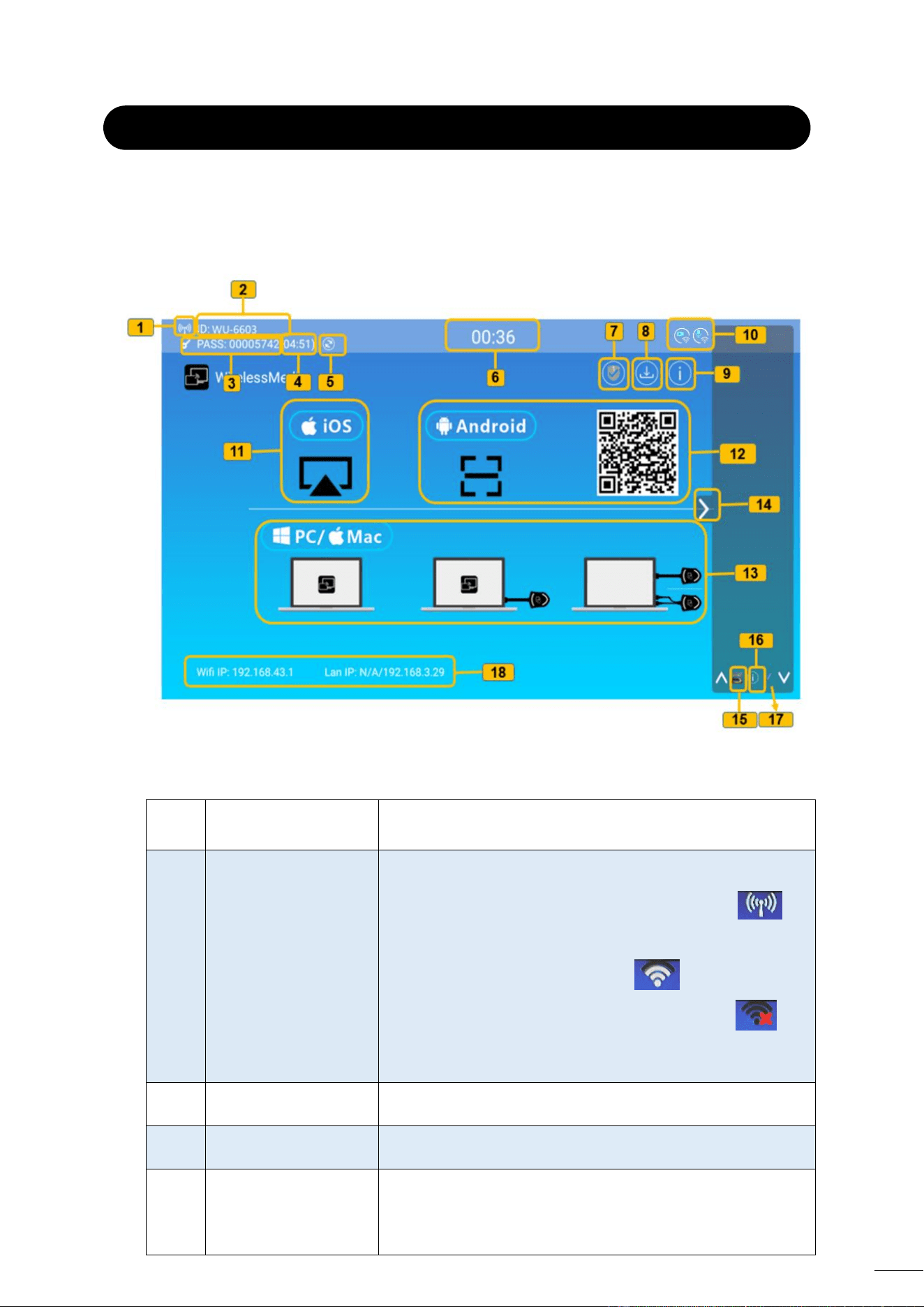
4.8 USB Conferencing Devices Connection
P35 supports one more USB Camera and USB Speaker & Microphone over WiFi sharing to start
meetings with conferencing software’s such as Skype, Zoom, Microsoft Teams, etc.
It can choose and use USB-B or Wireless two mode to do the communication with USB
camera and USB Speaker & Microphone that is connected to the P35 base unit.
When the base unit is on Wireles mode and there is one more USB camera connected,
it can switch different camera to use by dongle button, WirelessMedia application,
Web GUI.
The WirelessMedia application must be open on the computer when it is going to do
the video conference via Wireless mode even though it is using the transmitter.
To recognize the USB camera and USB Speaker & Microphone in the conferencing
software such as Skype, Zoom, Microsoft Teams so on, it must be open the
WirelessMedia application on the computer when it is using the Wireless mode.
15
5. START-UP and OPERATION
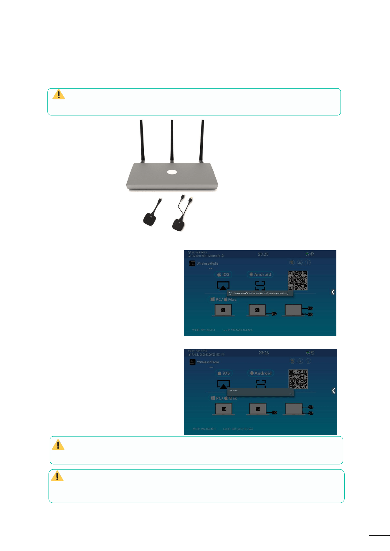
5.1 Home Screen
When a user connects the P35 base unit to the HDMI display, the following Home Screen is
displayed:
ID
Item
Details
1
Wifi working mode
Wi-Fi Direct mode: Internal access point available.
Networking mode: The router connected to Wi-Fi has been
established, which is more secure.
LAN networking mode: Access point is turned off.
2
ID
The name of the ID is the SSID.
3
PASS
Password of the base unit.
4
Password timer
For display only, when timer is enabled.
Automatically counts down and the password will change.

16
5
Wifi password refresh
Manually generate new password.
6
Time
Displays current time. If base unit has access to a time
server through wireless or LAN connection, time code will
be set automatically.
7
Security level
Clicking on the icon a pop-up window will appear, displaying
the security profile currently selected amongst the three
levels available.
8
Download button
Clicking on this icon will create a USB launcher drive
containing application and user manual.
9
Info
Clicking on this icon will show / hide Network information of
the Home screen.
10
Cameraµphone
icon indicator
It is only displayed accordingly a USB camera or microphone
is connected to the P35 base unit. When lighted in green,
USB device is being used. Otherwise, is only connected.
11
IOS quick start
Steps to start sharing content wirelessly using Airplay on iOS
and macOS.
12
Android quick start
Steps to start sharing content wirelessly using an Android
device.
13
Windows/MAC quick
start
Steps to start sharing content wirelessly using a laptop.
14
Sidebar
Preview screen for all connected devices, whiteboard,
annotation.
15
Whiteboard
Click here to open the whiteboard function.
16
Info Indicator
When casting, click this button to view the ID and password
to connect.
17
Annotation
Click here to open the annotation function.
18
Wifi IP
Lan IP
WiFi IP: address of base unit in wireless.
LAN IP: address of base unit in LAN.
“N/A” means the base unit is not connected to any WiFi /
LAN networks.
17
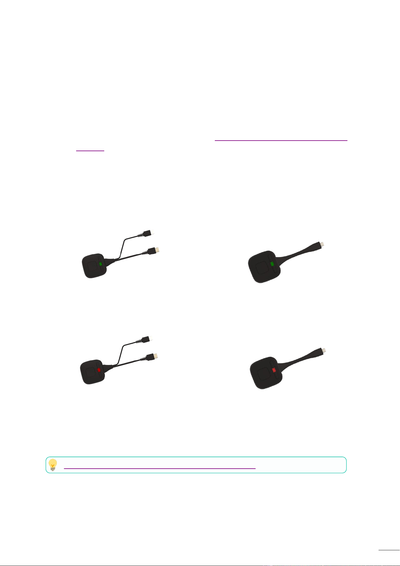
A transmitter can only be paired to one base unit and will always re connect to the one that
was last paired to.
Once a transmitter is plugged, a message
indicating that wireless transmitter is
booting will be displayed.
After completing the pairing, the message
table displays “Succeeded to pair!” on the
home page, as shown. Then, the
transmitters can be unplugged and used
for screen sharing content.
If error-message “Configuration fail” is displayed, check the connection of USB/type C to
keep stable after plug-in and try again.
After changing the SSID / WiFi channel in Web GUI settings menu, all the transmitters must
be paired again. Transmitters that need assigning to another P35 base unit must be paired again.
time.
5.2
Pairing
WMT-H55
and
WMT-C55
with
base
unit
Connecting
WMT-H55
(HDMI
wireless
transmitter)
to
USB
Type
A
port
or
WMT-C55
to
USB-Type
C
port
will
start
pairing
process
automatically.
They
should
be
connected
one
at
a
18
5.3 Wireless Presentation Mode
P35 can be used to wirelessly share the screen of AV sources. P35 can mirror 5 sources onto main
display simultaneously, which supports PC/Laptop and mobile devices.
See chapter LED Indicator for further information on LED status.
WMT-H55
5.3.1
Screen
Sharing
using
WMT-H55
and
WMT-C55
1.
Pair
WMT-H55
or
WMT-C55
to
P35
base
unit,
see
chapter
Pairing
WMT-H55andWMT-C55
with
P35.
2.
Plug
WMT-H55
to
the
USB-A
port
and
HDMI
port
or
WMT-C55
to
USB-C
port
of
the
device
that
is
going
to
share
its
content.
3.
LED
indicator
will
show
static
green
when
ready.
Touching
the
surface
will
start
wireless
presentation
and
LED
indicator
will
show
static
red.
4.
Touching
the
surface
again
will
stop
wireless
presentation
and
LED
indicator
will
go
back
to
static
green.
WMT-H55
WMT-C55
5.
When
LED
is
static
red,
the
content
is
mirroring
to
the
main
screen
connected
to
the
P35
base
unit.
WMT-C55
19
5.3.2 Screen Sharing using WirelessMedia Desktop Application
WirelessMedia application is the launcher that lets the user screen share content with P35 base
unit wirelessly from any source device which hosts it (mac, PC…). Just copying the launcher to the
internal storage will let the user run WirelessMedia application.
Setting up WirelessMedia
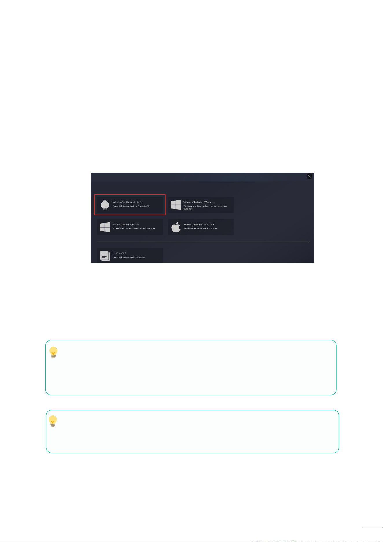
There are two ways of getting WirelessMedia desktop app:
1. Downloading from WEB page
Application can be downloaded from the website by connecting the device (laptop /
Android) to the same network as the P35 controller.
2. Automatically create startup programs
By connecting the USB flash drive and clicking the download icon on the home page, the
application can be downloaded to the root directory of the USB flash drive and then copy
to the computer.
The first time that user connects laptop with P35 over WiFi, when the application detects
that unit is connected to camera, mic&speaker, it will pop out the message bar indicating to install
a virtual driver to activate USB over WiFi function.
The virtual driver is only for video conferencing, user can normally mirror desktop without it
installed. If the P35 is not connected with camera, mic&speaker, it will not pop out message to
install driver, user could mirror desktop as well.
20
Starting and Operating WirelessMedia application
Once WirelessMedia app is copied into the local storage of the Laptop, it is ready for use.
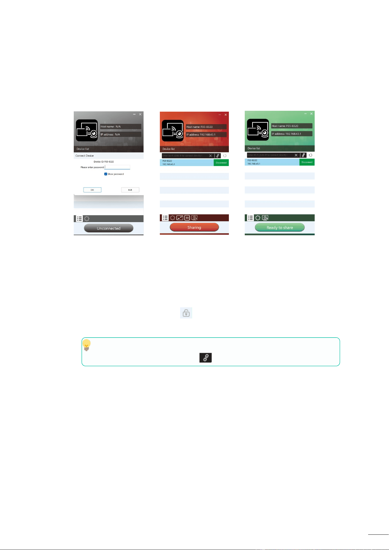
1. Open WirelessMedia application on the source device. The available P35 switcher will
show if source device and the switcher are on the same network.
2. Connect the laptop to WiFi network displayed on the Home Screen (“Guest”, “Staff”),
or connect to the LAN on the network using a network cable.
3. Double-click the WirelessMedia application. A list of all available P35 base units in the
same network will be displayed. select the device to connect to. The connections are
password protected (lock icon ).
4. Enter P35 password and click “connect”, the system is ready to share.
Manually connection by entering the name (SSID) or IP address is also possible if
base unit is not appearing. (click icon).
5. WirelessMedia app layout will turn to green. Clicking “Ready to share” will start
sharing content with the main display connected to the P35 HDMI output. When
window colour is static red, the desktop is mirroring to the main screen.
6. Clicking “Sharing” will stop sharing content. Window colour is static green again.
21
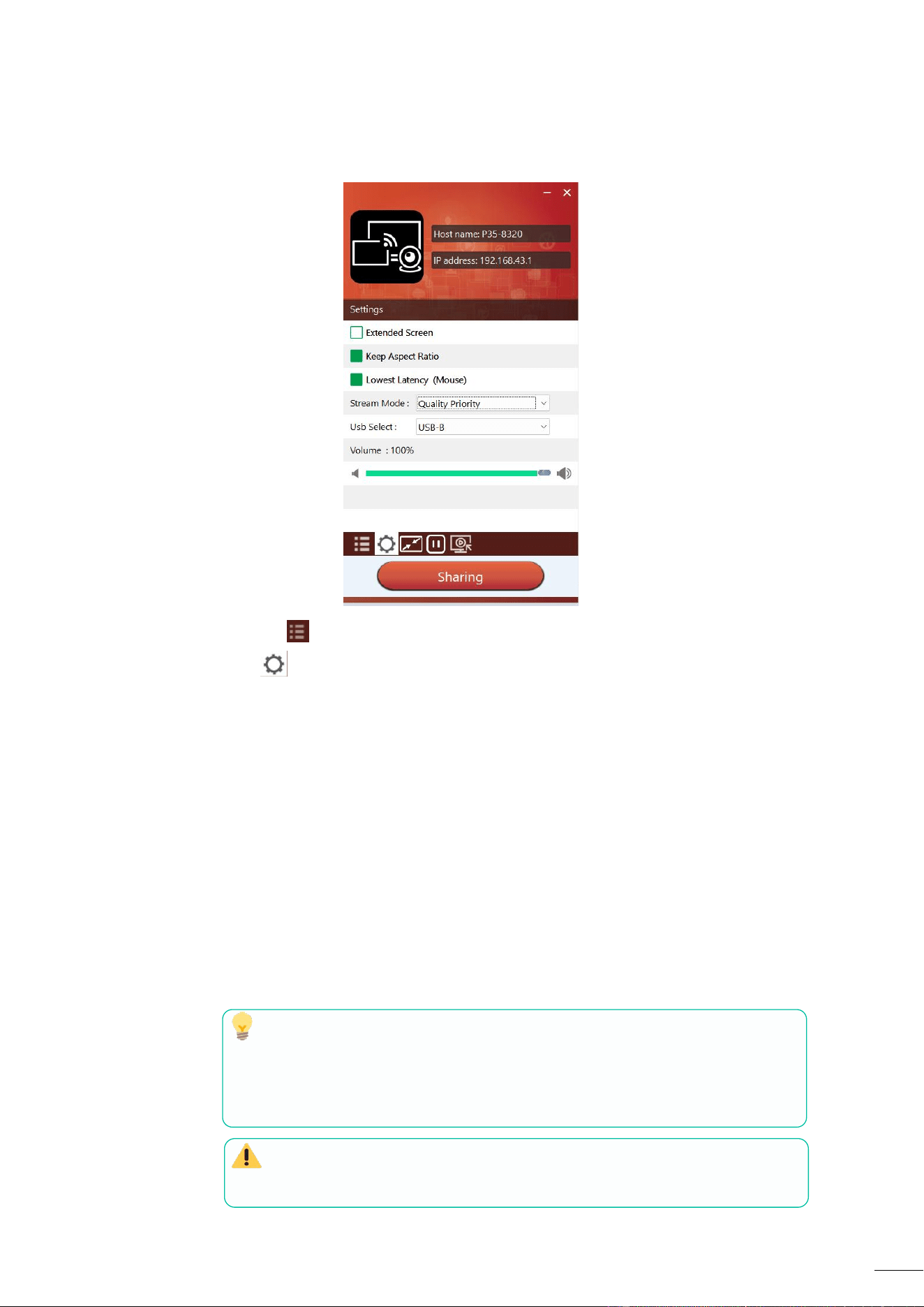
WirelessMedia Settings
1. Device List
2. Settings
Extended Screen:
Transfers extended desktop of active source.
The primary screen (1) is displayed on the laptop and the virtually extended
screen (2) is displayed on the main screen. If the PC has already connected an
extended screen (3), the extended screen (2) will always be displayed on the main
screen.
For the first time use of function “Extended Screen”, click the “Extended Screen”,
will pop out a message to indicate the installation of the “ExtendedDisplay” driver.
Click “yes” to continue, once installed, the Extended screen function is ready to
use.
If Extended Screen feature is selected, Windows automatically switches to
“Extended Mode”. If you stop the transfer with “WirelessMedia” (Pause),
Windows remains in " Extended Mode" until pressing "Windows key + P" on the
laptop to select the "PC screen only" mode.
In macOS, Extended desktop (“Use a Separate Display”) only via AirPlay,
when activated for Display on WirelessMedia app.

22
Keep Aspect Ratio:
This parameter will apply the original aspect ratio of the main screen.
Lowest Latency (Mouse):
The setting is applied individually on every WirelessMedia host device only. The
shape of mouse-pointer is equal to the shape in the application used. This
parameter significantly improves the mouse response (approximate latency is
under 20ms).
Stream Mode:
This parameter will adapt the performance to fit the desired application:
o Fluency Priority: (Default) Image transmission delay is small, image
resolution will be lower, suitable for PPT presentation mode.
o Quality Priority: The image resolution is relatively high, but when the
image content is complex, the transmission delay will be relatively larger,
suitable for watching video.
Usb Select:
o
USB-B: (Default) P35 base unit now is in wire mode, base unit is
connected with computer by using type B port line.
o WirelessMedia: P35 base unit now is in wireless mode, base unit is
connected with computer by using the wifi network.
Volume Slider:
This parameter will adjust the playback volume of the main screen when
presentation mode is in use.
Not available in macOS
3. Full Screen
By clicking full screen icon on PC UI interface, or long press the wireless transmitter,
the content will be full displayed on screen. Click or short press again, will get the
screen back to quad view mode.
4. Screen Freeze
By clicking the screen freeze icon on the interface or pressing the transmitter left
button, the screencast content will be frozen. it will cancel the freeze by clicking
again.
5. Screen Capture
By clicking the screen capture icon on the interface, the screen capture window will
open, and you can see the content of the main screen or sub screen.
23
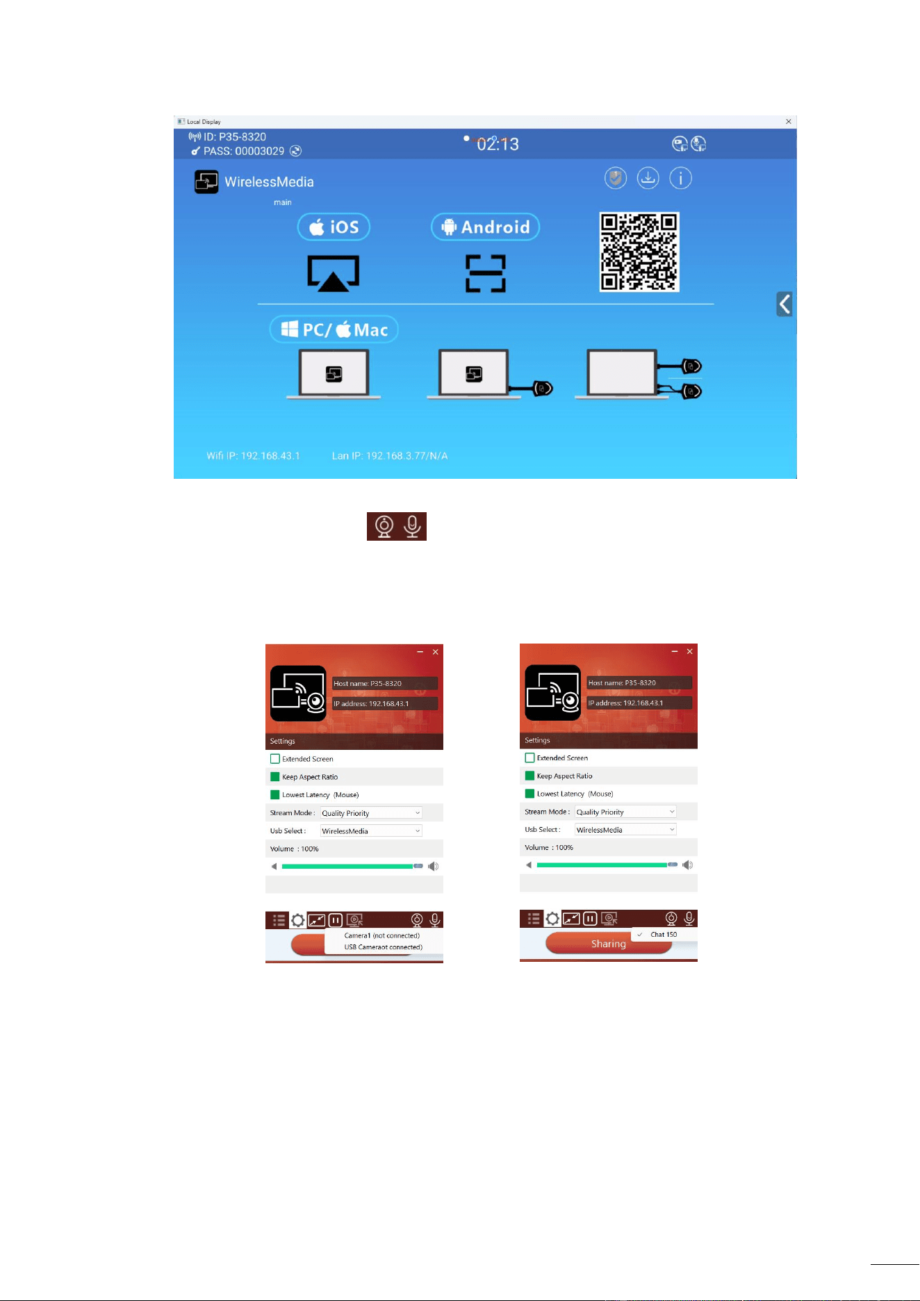
6. Camera & Mic (Option)
When insert the camera & Mic device into the base unit, the corresponding icon will
be shown on the software UI. If there is one more camera & Mic device inserted into
the base unit, it can use the mouse to click the icon to choose the camera & Mic that
wants to use.
24
5.3.3 Screen Sharing using Airplay
On iOS and macOS devices a user can stream his screen or sound wirelessly to P35 base unit via
Airplay protocol.
1. Connect the iOS or macOS device to the same WiFi network that P35 is connected too.
2. Show the control centre. Click the Airplay icon on your iOS and macOS device and
select the target P35 to start sharing content with the P35.
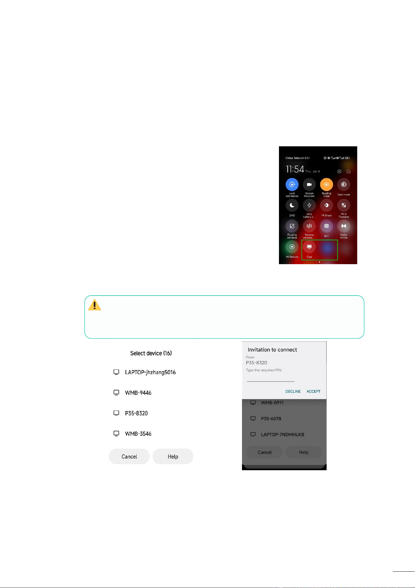
5.3.4 Screen Sharing using Miracast
Android Devices
1. WiFi must be enabled.
2. Click the Wireless projection icon on the control centre.
3. Select P35 SSID and click to connect.
Under Security Level 1 mode, there is no need to enter password to connect.
Under Security level 2 and Security level 3 mode, it will need to enter password on P35
Home Screen to connect and start casting.
4. After entering password, your mobile content will be shown on the display.
5. Click the “Wireless projection” icon again to stop mirroring.
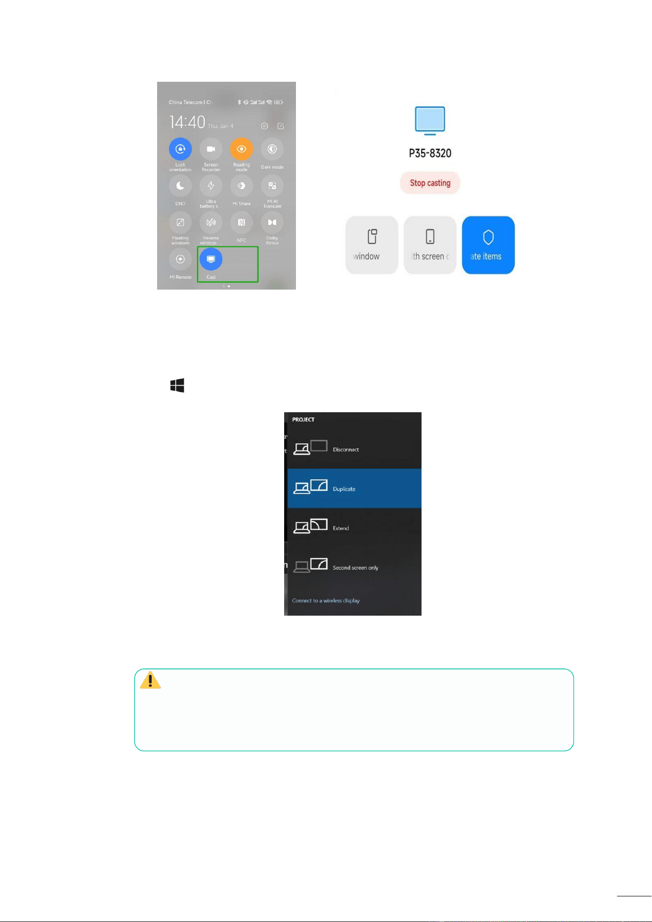
25
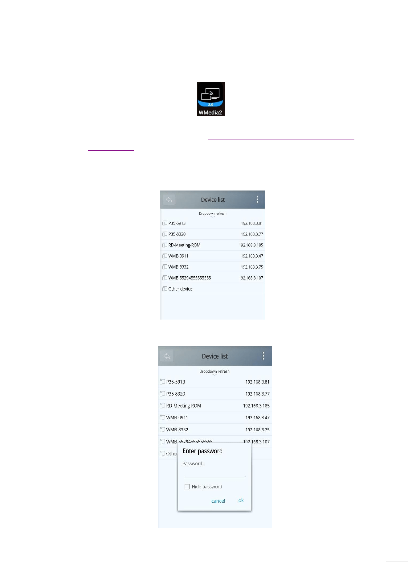
PC
1. WiFi must be enabled and connected to the same network as P35 base unit.
2. Press + P and then click “Connect to a wireless display” in the pop-up window.
Under Security Level 1 mode, there is no need to enter password to connect.
Under Security level 2 and Security level 3 mode, it will need to enter password on P35
Home Screen to connect and mirror. After entering password, your mobile content will
be shown on display.
26
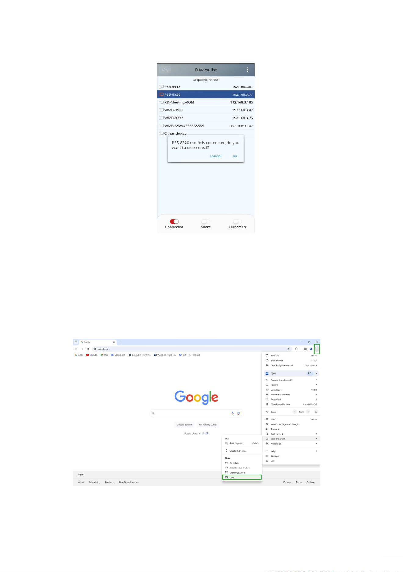
5.3.5 Screen Sharing using Android application
Android Devices
1. Download WirelessMedia application (see chapter WebGUI Setting Management &
Configuration).
2. Connect your Android device to one of the displayed WiFi networks.
3. Open the WirelessMedia application in the Android device, and then click the device
list refresh button.
4. Select the P35 to connect to and enter password to start screen sharing.
27
5. Click again the button “Share Screen” to stop mirroring.
5.3.6 Screen Sharing using Chromecast
PC
1. Connect the PC and P35 on the same network.
2. Open Chrome browser.
3. Click “cast” to connect Chromecast function.
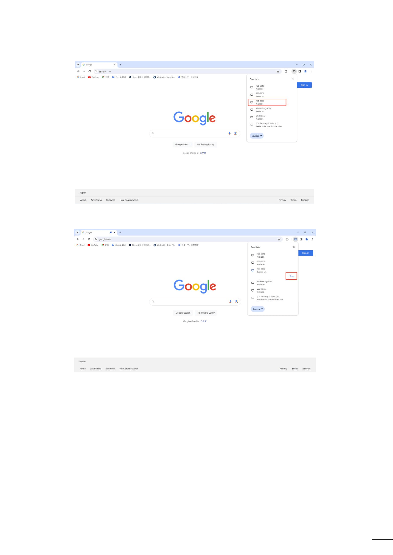
28
4. Click P35 SSID to start sharing content.
5. Click P35 SSID again to stop sharing content.
5.4 Wireless Conferencing Mode
P35 allows to conduct a video conference using the room USB conferencing devices over WiFi.
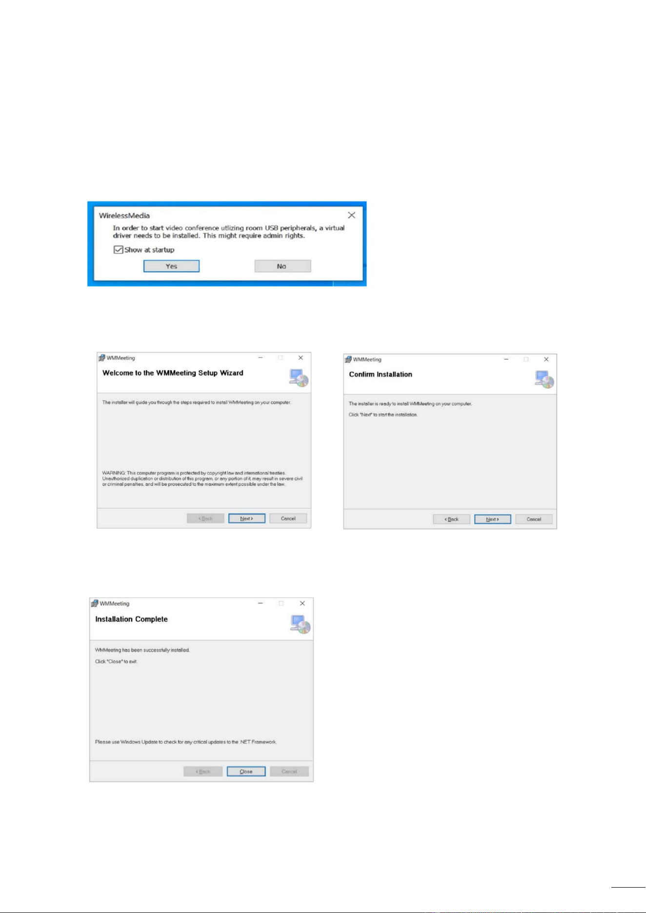
5.4.1 WMMeeting Driver Installation
WMMeeting virtual driver needs to be installed in the PC to support USB over Wifi.
29
Note:
Users only need to install the driver for the first time.
>> When runs the WirelessMedia application for the first time or connect to the transmitter for
the first time, a prompt to install the driver will pop up.
>> Click “Next” button to continue installation.
>> Click “Done” button to finish the installation
30
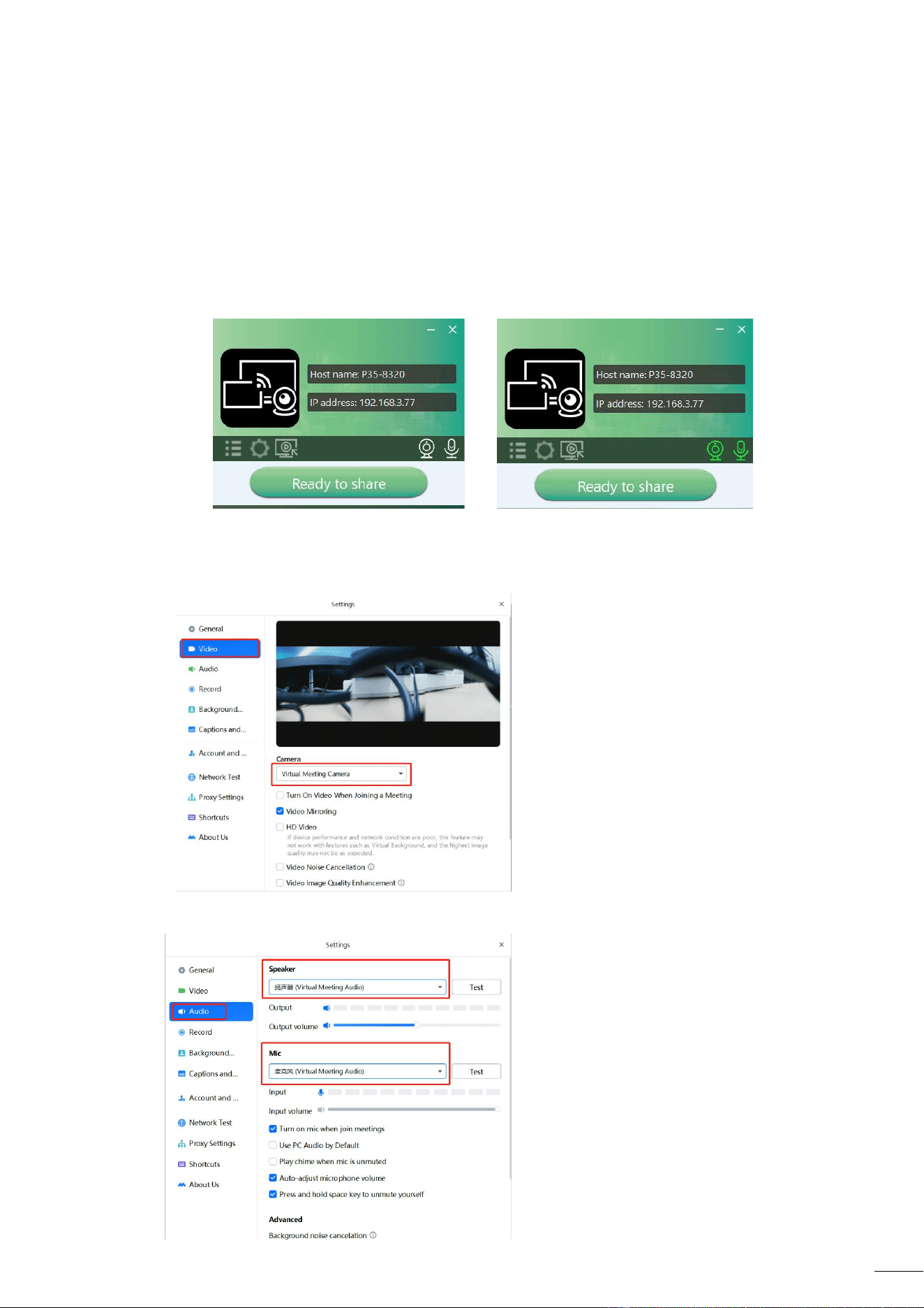
5.4.2 Conference via WirelessMedia application
1. Connect the USB conferencing devices to the P35 USB ports. Camera and microphone
icons will appear on WirelessMedia control bar.
o White icons: indicate the USB camera and speaker/mic are connected.
o
Green icons: indicate the USB camera and speaker/mic are connected and in use
by any given application.
2. Launch Video conferencing application.
Select “Virtual Meeting Camera” as video device.
For Speaker & Microphone, select “Virtual Meeting Audio”.
31
3. Clicking “Ready to share” button in WirelessMedia application will start wireless
conferencing sharing.
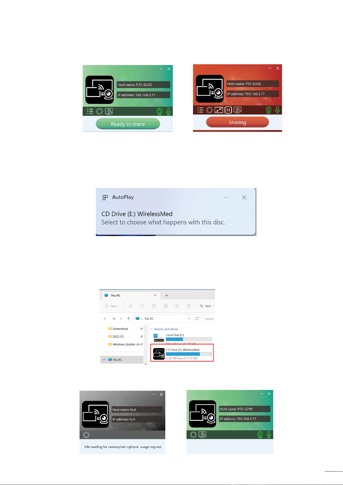
5.4.3 Conference via transmitter
Connect the USB conference device to the P35 USB port
The "WirelessMedia" CD drive will automatically pop up as below photo shown when
the transmitter is plugged into the computer. Click the "WirelessMedia" CD drive.
Note:
It can also double-click the "WirelessMedia" CD-ROM drive in the computer drive letter to
run the application, for first-time use only. The application will automatically run on your
PC for next use, no need to follow this step again.
Open the WirelessMedia application for video conference use.
32
5.4.4 Switch cameras during wireless meeting
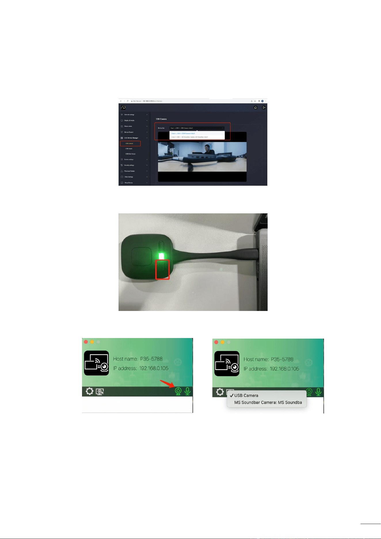
Switch via Web GUI. Click UCC-Device Manager > USB Camera, then it can select
cameras from the device list and preview them.
Switch by right-pressing button on the transmitter.
Switch the camera through the WirelessMedia application, click the camera icon.
Note:
>> If you connect 2 cameras, at least 1 of them need be connected with USB port 1.
>> you need make sure now the USB hub is switched to the wireless source.
>> the camera switching feature is only for wireless conferencing, not working with wired
USB-B room PC mode.
33
5.4.5 Screen sharing to remote
local screen content including annotations and whiteboard shares to remote. It can share
to remote participants.
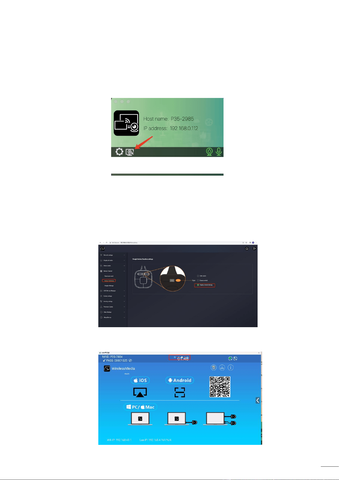
Open WirelessMedia App in the background and click the screen capture button
Note:
It will not work when the number of screencasts exceeds 2
It can define the right click button of the transmitter as "Display content sharing" in
the web, and then just press the right button to activate this function.
A window appears that captures the content on the screen.
34
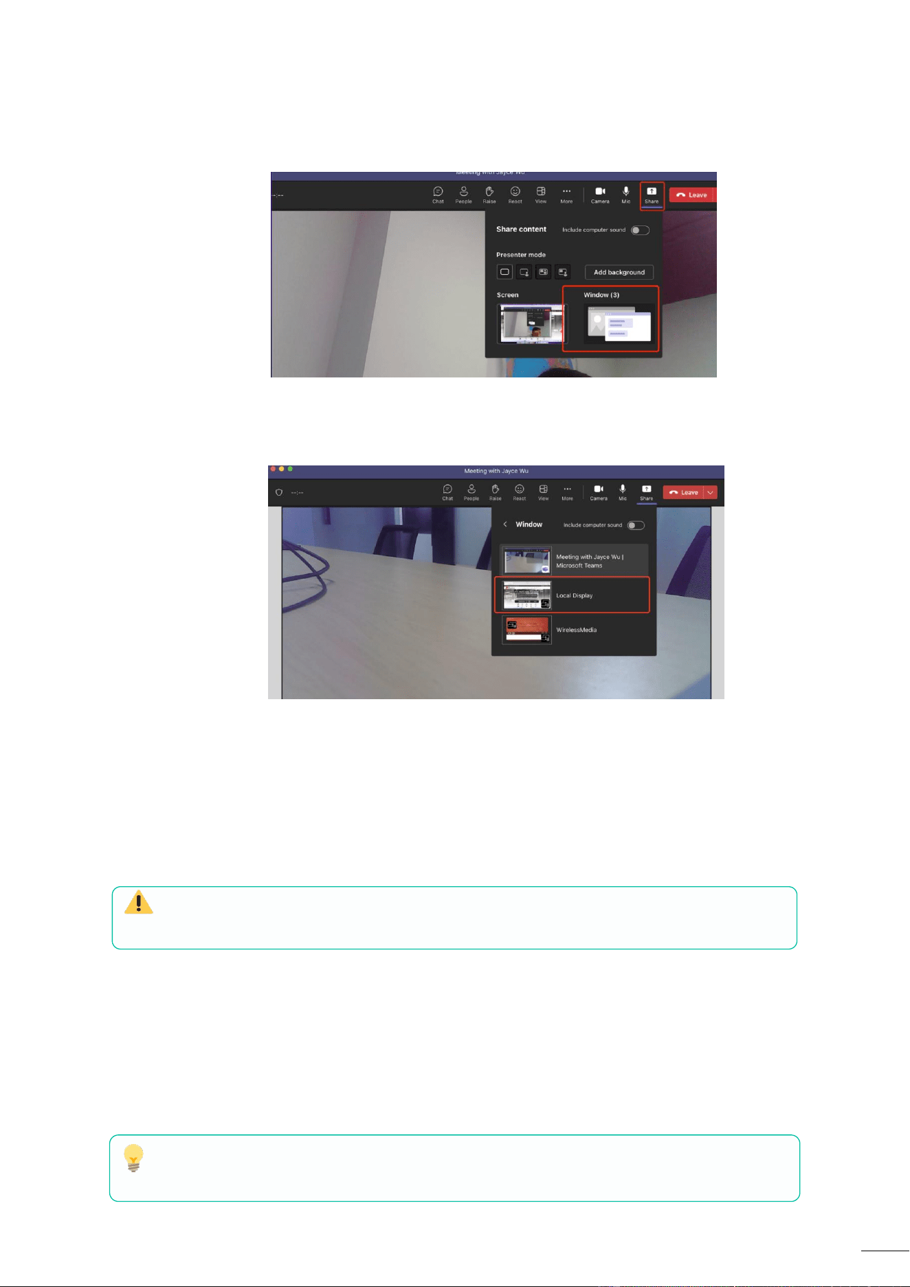
Return to the VC app like Teams, click the "Share" button and then click "Window"
Select "Local display" so remote participants can see the shared content on the local
screen.
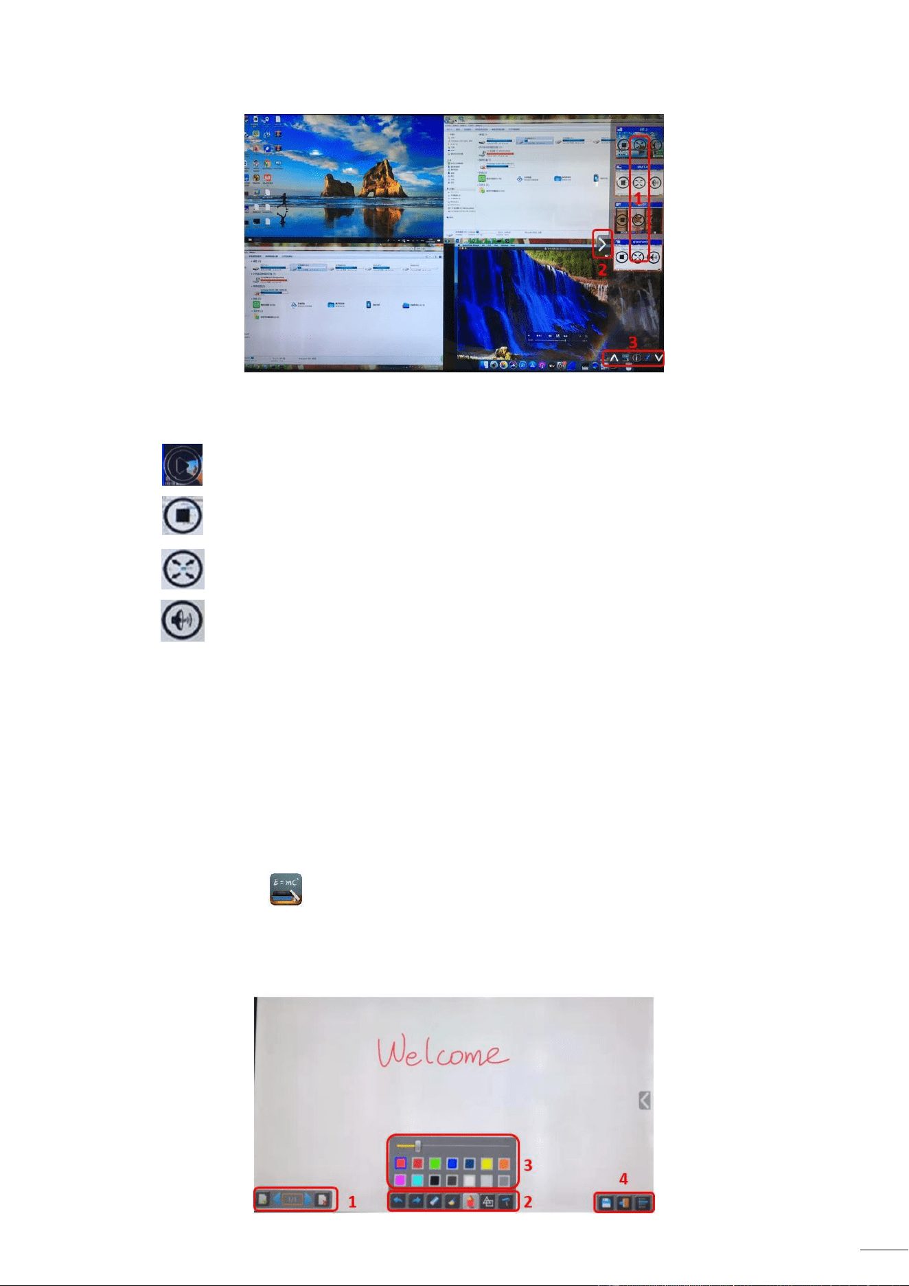
5.5 Moderator Preview Window
P35 includes a moderator preview window that will let the user choose which of the online
devices is displayed on the main screen, turn on and off wireless casting on any device or control
volume playback.
In order to show, hide or manage moderator tab, a USB HID compatible device connected
to the P35 base unit is necessary (Touchscreen, mouse…).
Preview windows of all connected transmitters, WirelessMedia app users and Airplay / Miracast /
Chromecast screen sharing devices will appear on the tab. Various window prefixed layouts can
be selected on Moderator section of WEB settings.
Five users are allowed to present simultaneously and 14 more can be connected to P35 base
unit in standby.
35
Moderator Preview Control Buttons:
1
Click to start transmission.
Click to stop mirroring the current participant.
Click to make this device full screen on main screen.
Click to adjust the volume of connected participant.
2
Arrow to show moderator tab.
3
Whiteboard and Annotation. For further details, see below.
5.6 Whiteboard & Annotation
Whiteboard and Annotation requires an USB HID compatible device, such as interactive white
board, touch screen or mouse. There are two different modes;
5.6.1 Whiteboard
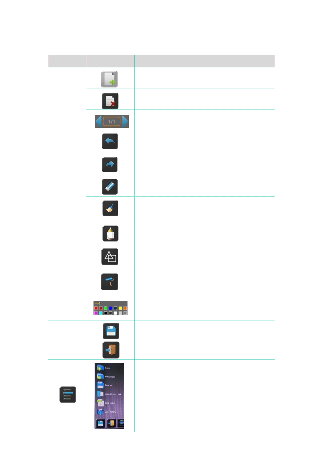
A white board is brought up that will let the user to write notes, draw content. It allows different
figures, colours and background. To start Whiteboard mode, click on the Home Screen.
36
Use the toolbar to select one of the following functions.
ID
Icons
Function
Tool bar 1
Add an empty page.
Delete current page.
Display previous or next page.
Tool bar 2
Undo: one step backward in changes.
Redo: one step forward in changes.
Erase part of drawings or annotation, change
diameter by a longer tap.
Clear the entire drawing/writing on the screen.
Pen allows writing/drawing in different colours.
Draw basic geometric shapes.
Select colour of board, the drawing will be kept.
Tool bar 3
will pop up, when “Pen” or Draw shape or Select
colour of board is selected, for individual change of
size of Pen, Shape or colour.
Tool bar 4
Save the current screenshot on local storage
(PNG+WMN).
Close Whiteboard to go back to Home Screen, actual
project can be saved on local storage (WMN).
File options
Open WMN-file from local storage and
continue/edit an older project.
New project
Save as WMN on local storage in unit, it will be
erased after POWER-OFF.
Import from U disk stored project (WMN).
All pages are saved as PDF on local storage.
Clear history – delete all files on local storage.
37
5.6.2 Annotation
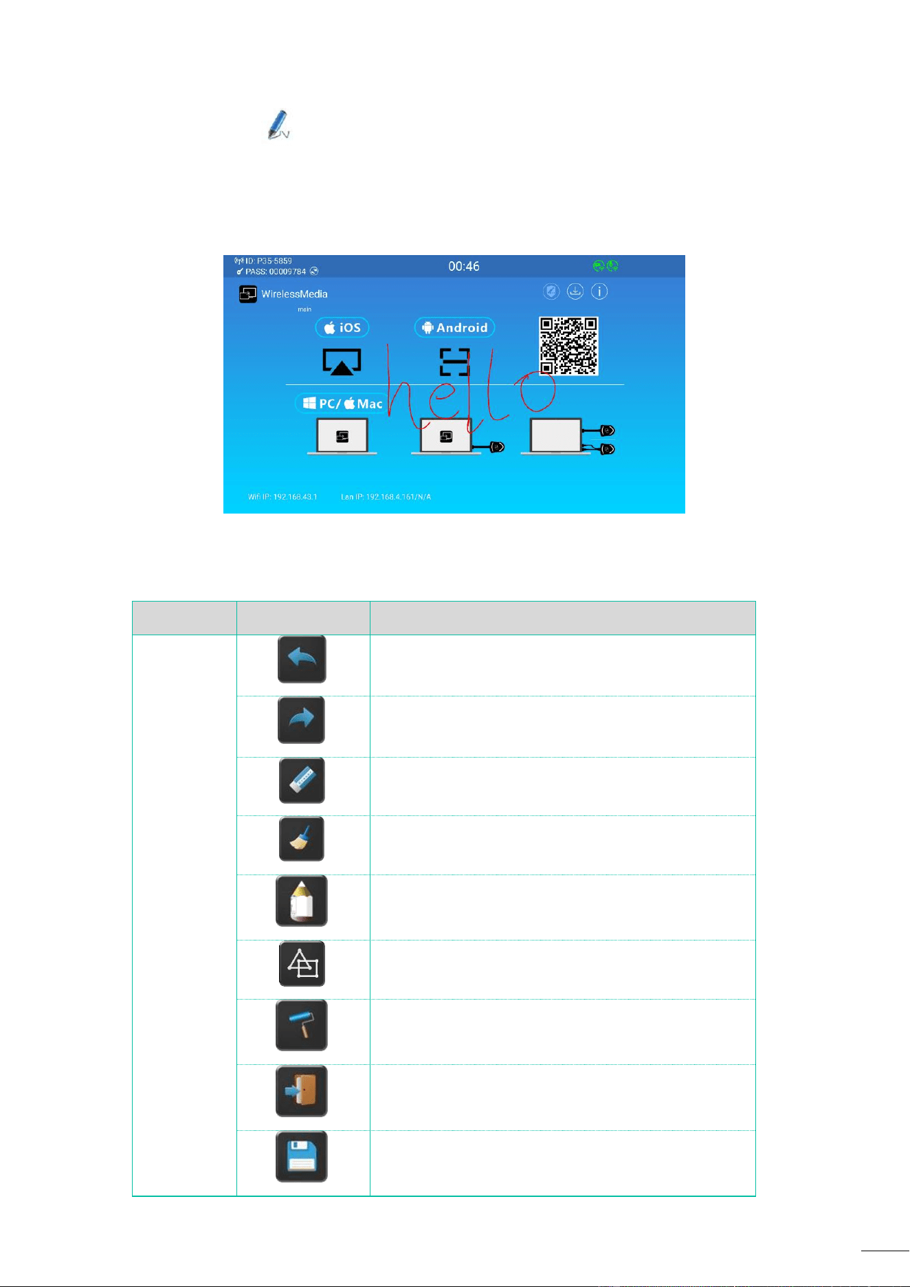
Allows the user to draw or write annotations in overlay within the presented content of the active
sharing devices. It allows different figures, colours, and background.
To start Annotation mode, click it on the Home Screen.
Use the toolbar to select one of the following functions.
ID
Icons
Function
Tool bar 1
Undo: one step backward in changes
Redo: one step forward in changes
Erase part of drawings or annotation, change
diameter by a longer tap
Clear the entire drawing/writing on the screen
Pen allows writing/drawing in different colours
Draw basic geometric shapes
Select colour of board, the drawing will be kept
Close Whiteboard to go back to Home Screen, actual
project can be saved on local storage (WMN).
Save the current screenshot on local storage (PNG).
38
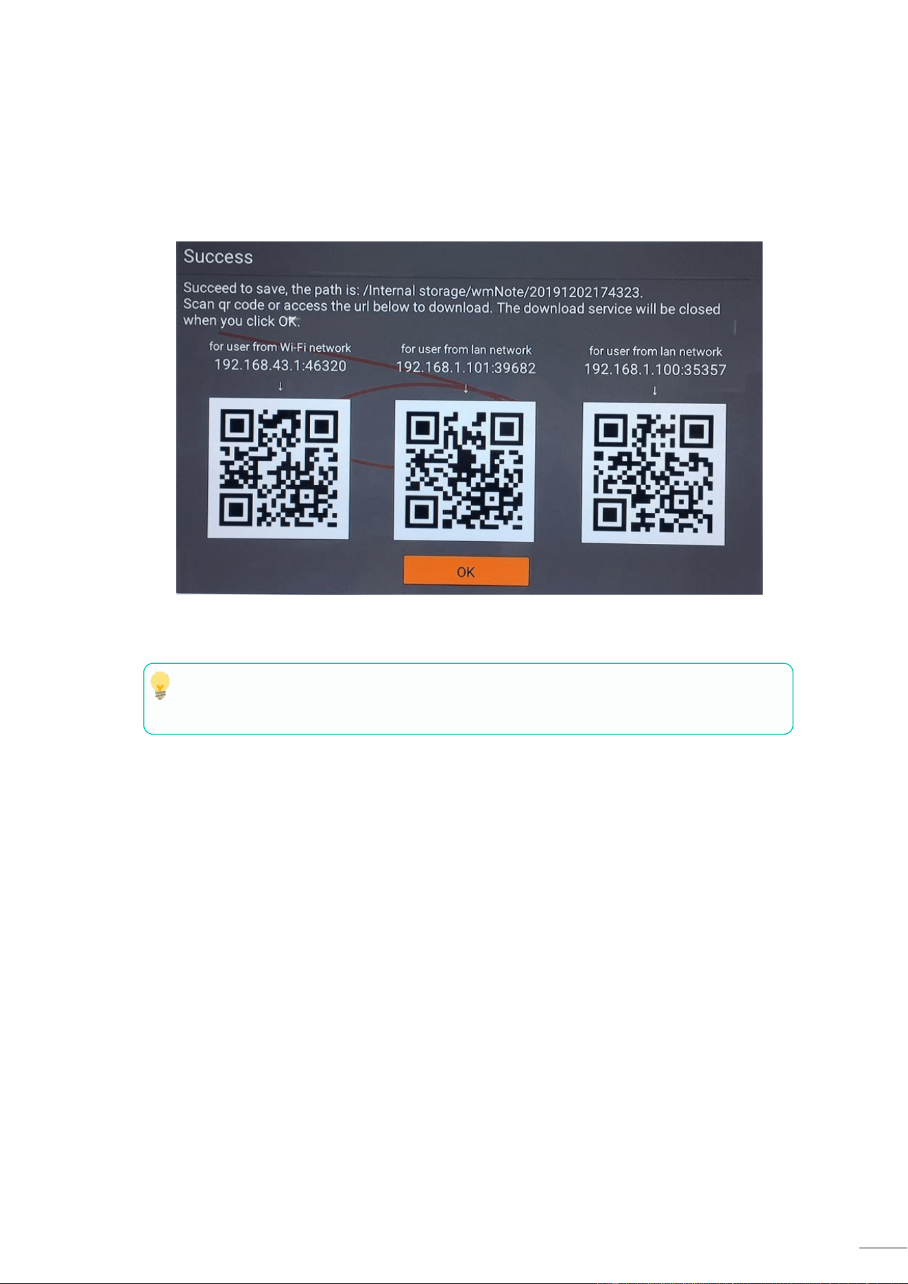
Download the Drawings to Connected Users
When saving a screen of Whiteboard or Annotation modes into internal storage of P35,
scanning the QR code or entering the given IP address in a browser will allow the user to
download the saved files.
Data can be copied to a USB disk and after connecting it to the P35, it can be imported
into the Whiteboard section with "Import from U disk".
39
6. WebGUI SETTING MANAGEMENT & CONFIGURATION
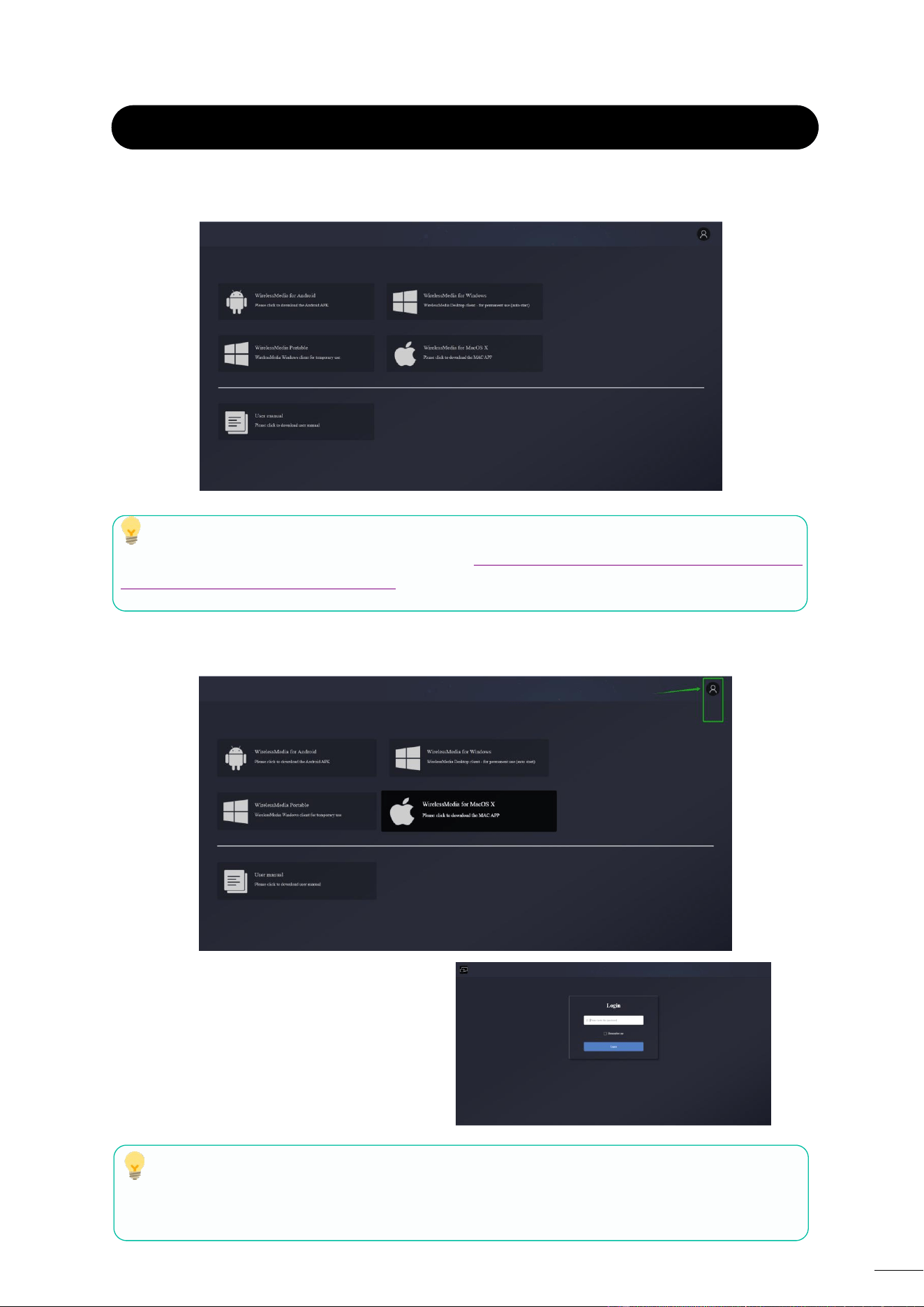
To access P35 WEB settings it is necessary to enter the base unit IP address in an internet browser.
The first page displayed will let the user download WirelessMedia app for all platforms.
If P35 is on “Wireless direct Mode”, first access P35 SSID and enter current password on
Home Screen page. IP address is 192.168.43.1. For further information on how to configure
network, see chapter Network Settings.
1. Click on the top right corner to enter into WEB Settings menu.
2. Login page will appear.
>> Default password: admin
Entering Login credentials will give access to the main WEB settings page where it will be
able to configure Network settings, Display & Audio, Home screen, Device Control, UCC-Device
Manager, System settings, Security settings, Firmware upgrade, Other settings, About device.
40
6.1 Network Settings
To take the full benefit of P35 features, it is important to configure and integrate the base unit
network settings according to the needs of the application required. P35 includes two
independent wired LAN and a WiFi network card.
The following sections can be accessed in Network Settings page:
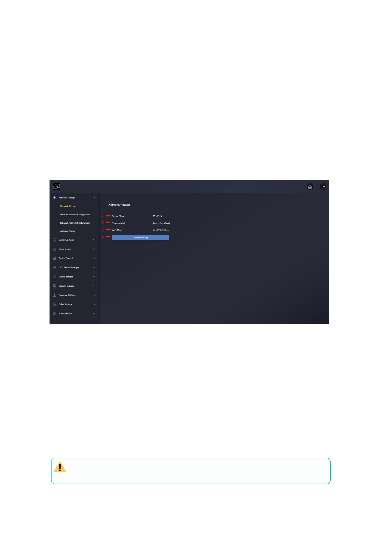
6.1.1 Network Wizard
This section allows the user to set the network working mode of P35.
1. Device Name: this parameter indicates current name assigned to P35.
2. Network Mode: this parameter tells the user which network working mode is currently
configured.
3. WiFi Mac: this parameter shows the MAC address assigned to the P35 network card.
4. Start modifying: Click to enter a network setup wizard is available to change network
working mode to properly integrate P35 into an existing wireless infrastructure.
Any
change
to
Network
mode
will
need
WMT-H55
and
WMT-C55
to
be
paired again
with
P35
base
unit.
41
6.1.1.1 Network Modes Configuration
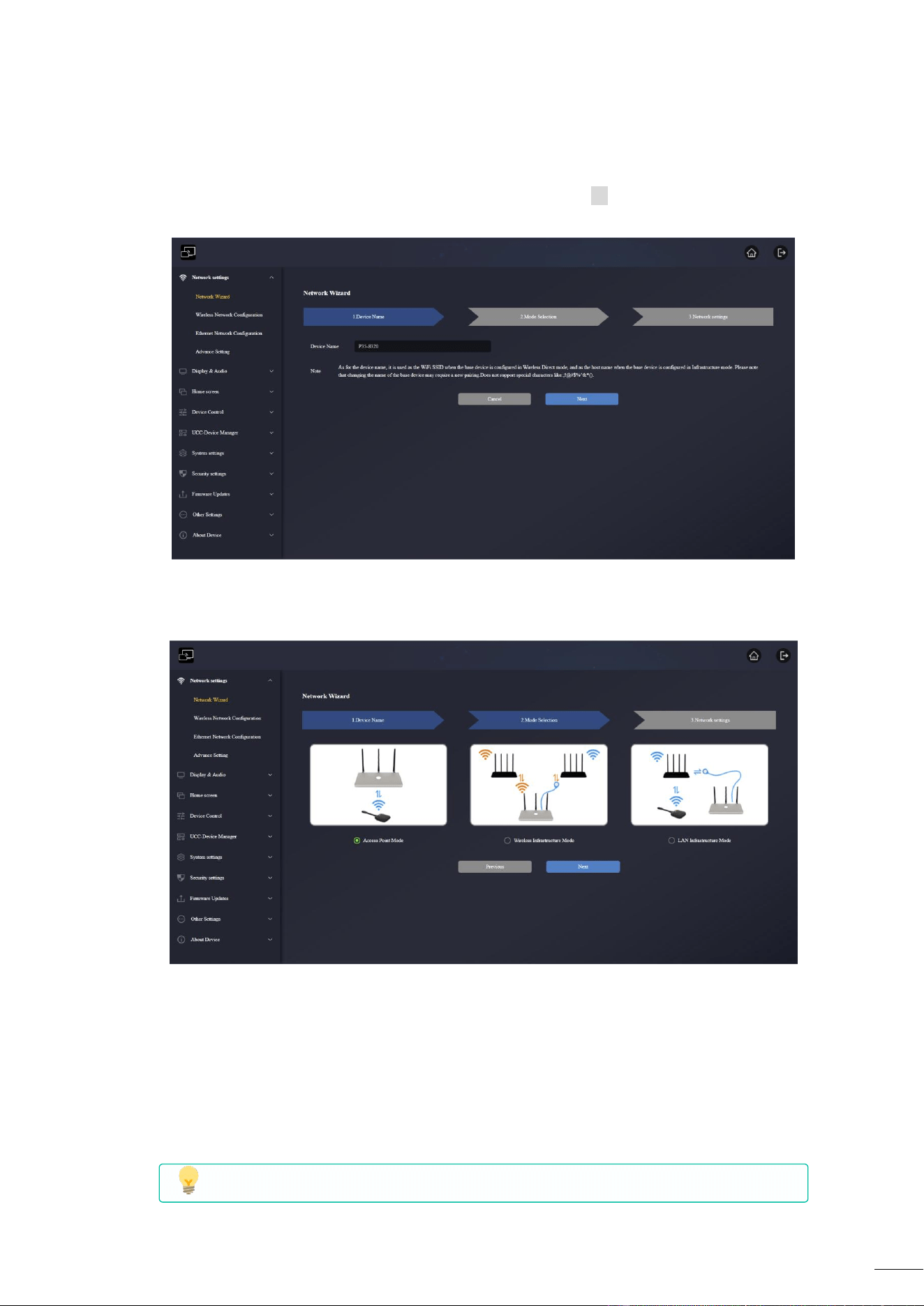
1. Device Name: Enter a device name for the Base-unit P35. Allowed characters are: "a-z",
"A-Z", "0-9", "-“, “_" and “space “, then Click “Next step”.
2. Mode Selection: Select the desired network mode and click “Next Step”.
Wireless Direct Mode
P35 unit starts up in the default standalone “Wireless direct mode” configuration after a
factory reset or the first time it’s being used. The base unit creates its own wireless access
point, which all devices need to connect in order to share content with base unit. This
option is best for temporary operation, small installations, and rooms without network
access or networks that do not allow network access for Guests, due to strict security
concerns, and are completely separated from the corporate network.
Under this mode, P35 can work without any other wireless network configuration.
42
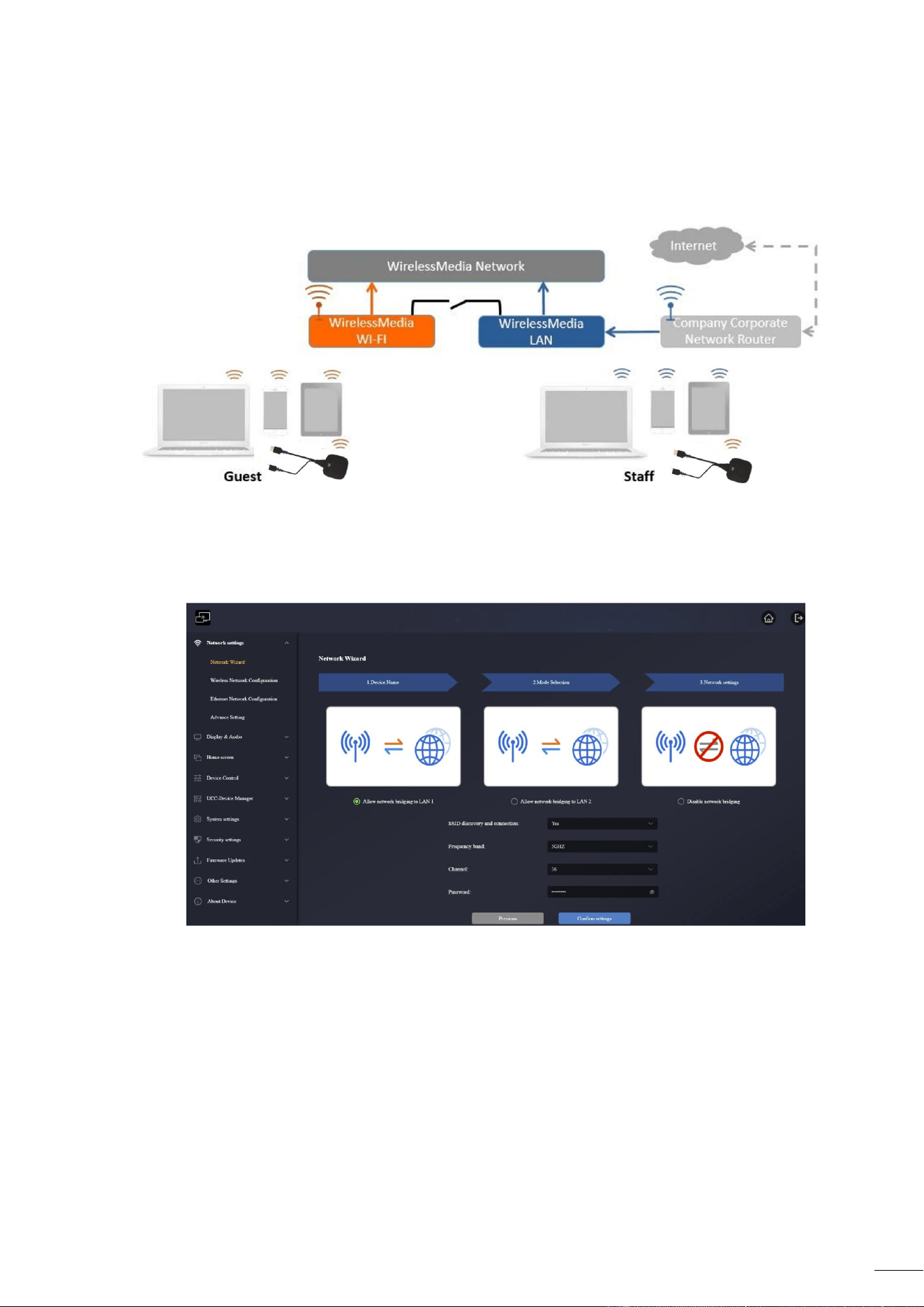
1. Click “Next step” to Set up WiFi access point.
There are three ways of connecting to Internet through P35 in “Wireless Direct
Mode”:
a) Allow internet access (bridging) via LAN 1: the source device is able to connect
to Internet if LAN1 port is available.
b) Allow internet access (bridging) via LAN 2: the source device is able to connect
to Internet if LAN2 port is available.
c) Disable internet access: the source device is not able to connect to Internet if
this mode is activated. Sometimes it is for safety requirements.
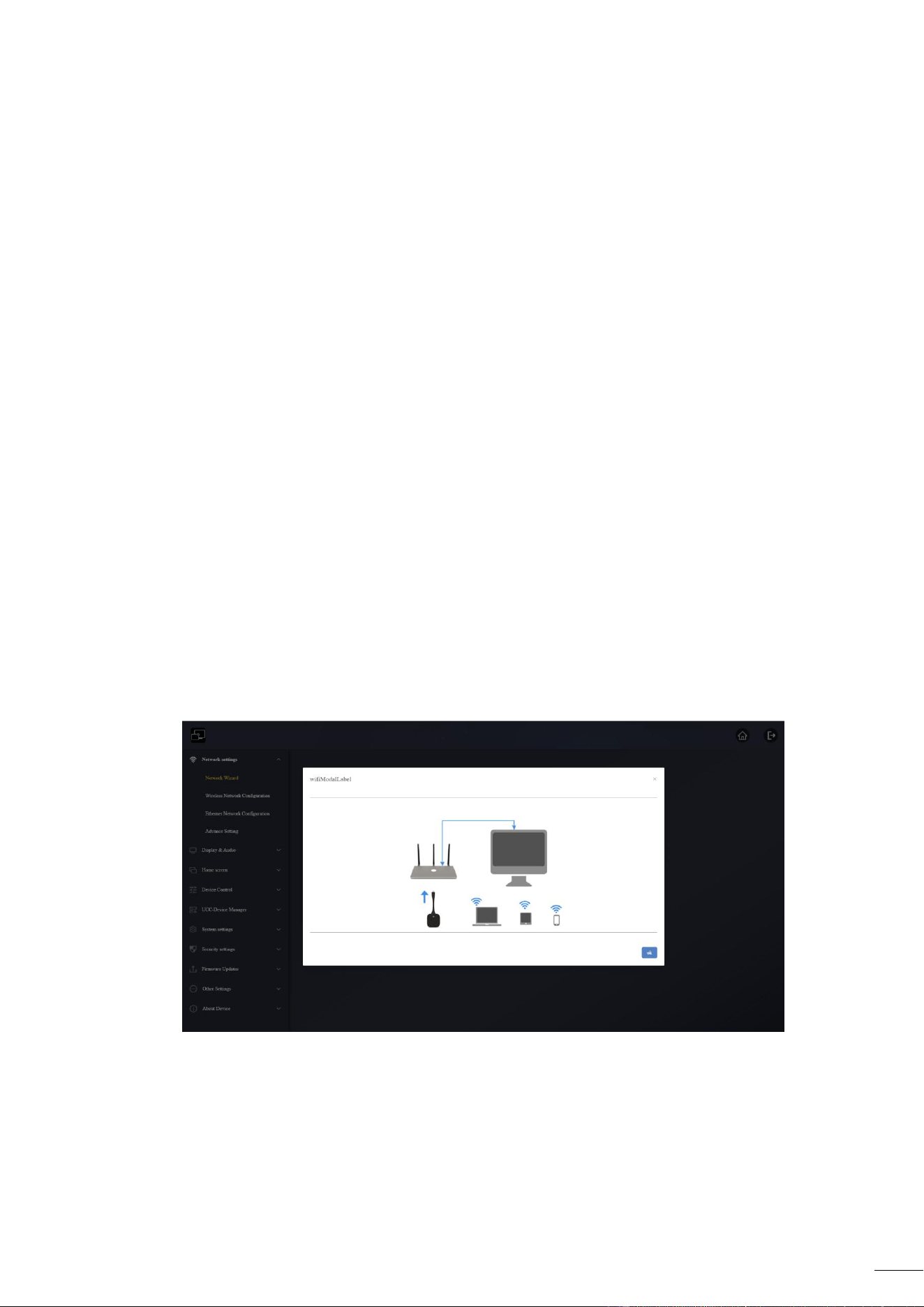
Just
pair
WMT-H55
/
WMT-C55
with
P35
base
unit,
connect
to
P35
internal
hotspot
and
open
WirelessMedia
app
or
use
Airplay,
Miracast
or
Chromecast
wireless
casting
protocols.
43
SSID discovery and connection: Select “Yes” to make P35 SSID visible and “No” to
hide it.
Frequency: Click to select 2.4 GHz or 5 GHz WiFi frequency. Default is 5 GHz.
Channel: Click to select the WiFi channel. Default is 5 GHz, Auto. If the WiFi channel
is changed, no new pairing of the wireless transmitter is necessary.
o 2.4 GHz frequency band: channels 1, 2, 3, 4, 5, 6, 7, 8, 9, 10, 11.
o 5 GHz frequency band: no need to choose 5G channel, system will choose
proper channel automatically. Default is 5 GHz, channel: 36.
o
Default channel (USA&China area): 36,40,44,48,149,153,157,161.
o Default channel (European area): 36,40,44,48.
Note:
Since channel 36 is supported all over the world, the default channel is 36.
Password: Click in the input filed to fill out the appropriate password with length of
8 characters.
2. Click “Submit settings” to finish configuration. Then, pair wireless transmitters with the
P35 again.
44
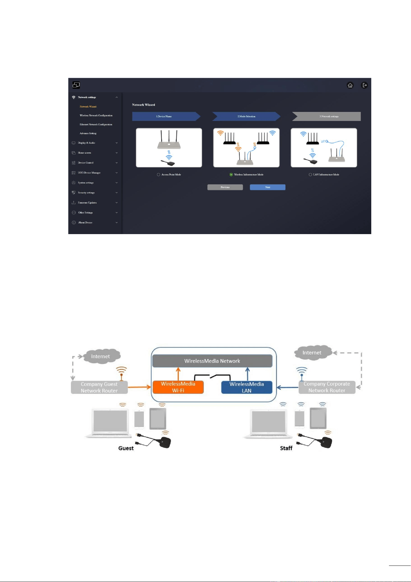
Wireless Infrastructure mode
P35 can simultaneously connect to a wired and a wireless network. The segmented dual
network of P35 provides two separated routing ways to connect to the base unit at the
same time. This is very useful for organizations, which have a wireless “Guest” network for
external visitors and a wired “Staff” network for their employees. Guest-users are not able
to access any resource on the internal network of the company. Guest and Staff have
internet access.
Under
this
mode,
users
will
be
able
to
present
with
WMT-H55
/
WMT-C55
/
Native
Wireless
protocols
(Airplay,
Miracast,
Chromecast).
WMT-H55
/
WMT-C55
will
be
connected
tothe
WiFi
access
point
of
“Guest”
network,
which
in
turn
is
connected
to
the
internal
WiFai
ccess
point
of
P35.
(They
can
also
be
configured
to
connect
to
the
enterprise’s
accesspoint.)
Mobile
devices
users
will
stay
connected
to
their
current
network
thus
have
accessto
their
normal
corporate
environment
as
well
as
Internet
access.
45
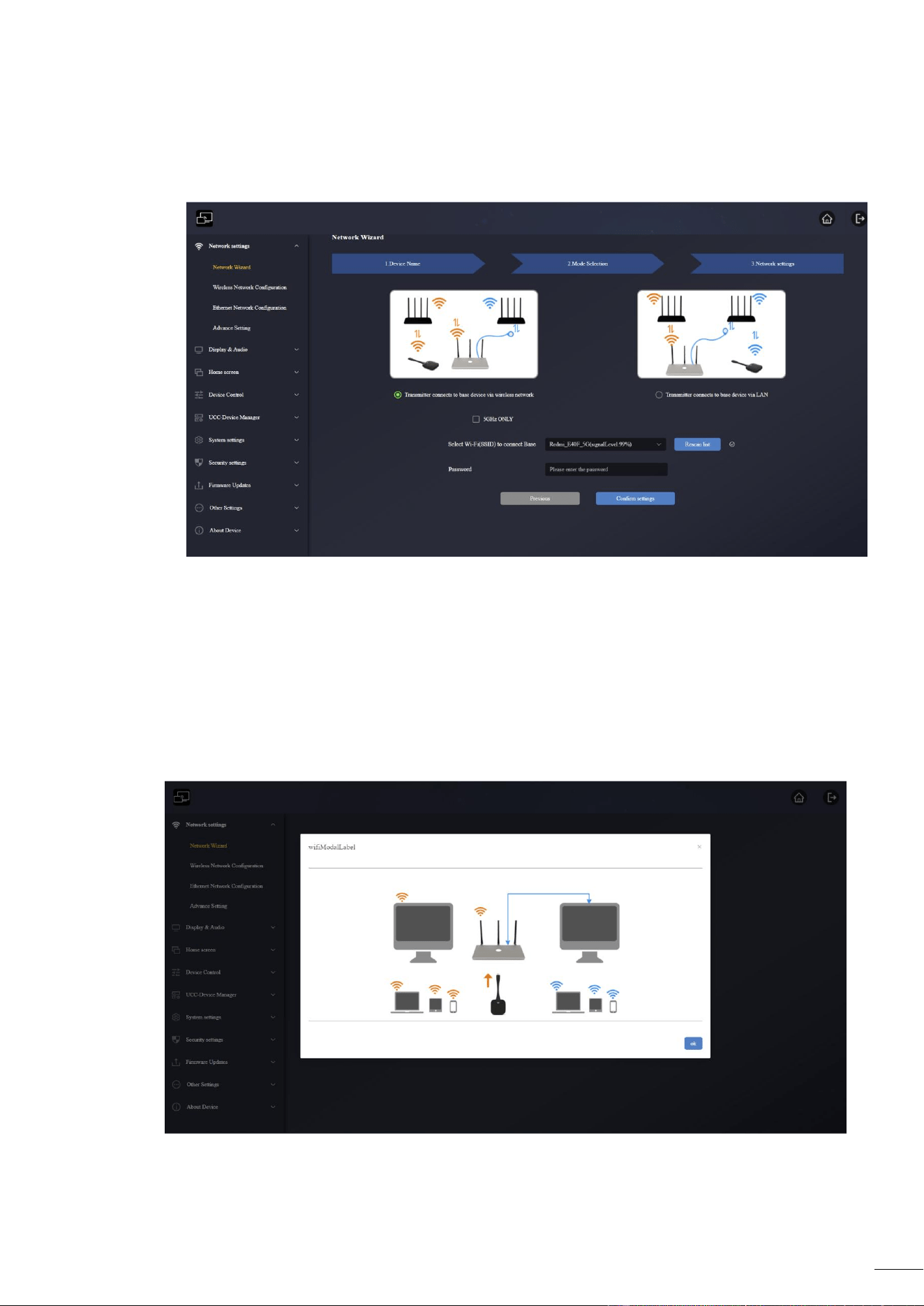
>> Transmitter conncts to base device via wireless network
1. Click “Next” to enter the configuration of this the network mode.
2. Choose “Transmitter conncts to base device via wireless network”, a wireless network
which is separate from the company LAN network for guest users.
Select SSID: Choose a wireless network to connect to P35 for guest.
Password: enter password to connect the P35 to the guest network.
3. Click “Confirm settings” to finish configuration. Then pair wireless transmitters with the
P35 again.
46
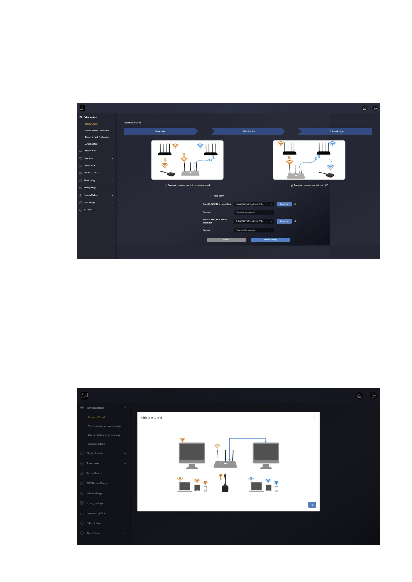
>> Transmitter connects to base device via LAN
Choose a wireless network for guests and a LAN network for staff.
1. Click “Next” to enter the configuration of this the network mode.
2. Choose “Transmitter connects to base device via LAN”, transmitter is for staff use.
Select Wi-Fi(SSID) to connect Base: Choose a wireless network to connect to P35 for
guest.
Password: enter password to connect the P35 to the guest network.
Select Wi-Fi(SSID) to connect transmitter: choose the same LAN network which P35
connects, to pair the wireless transmitter.
Password: enter password of the LAN network.
3. Click “Confirm settings” to finish configuration. Then pair transmitters with the P35.
47
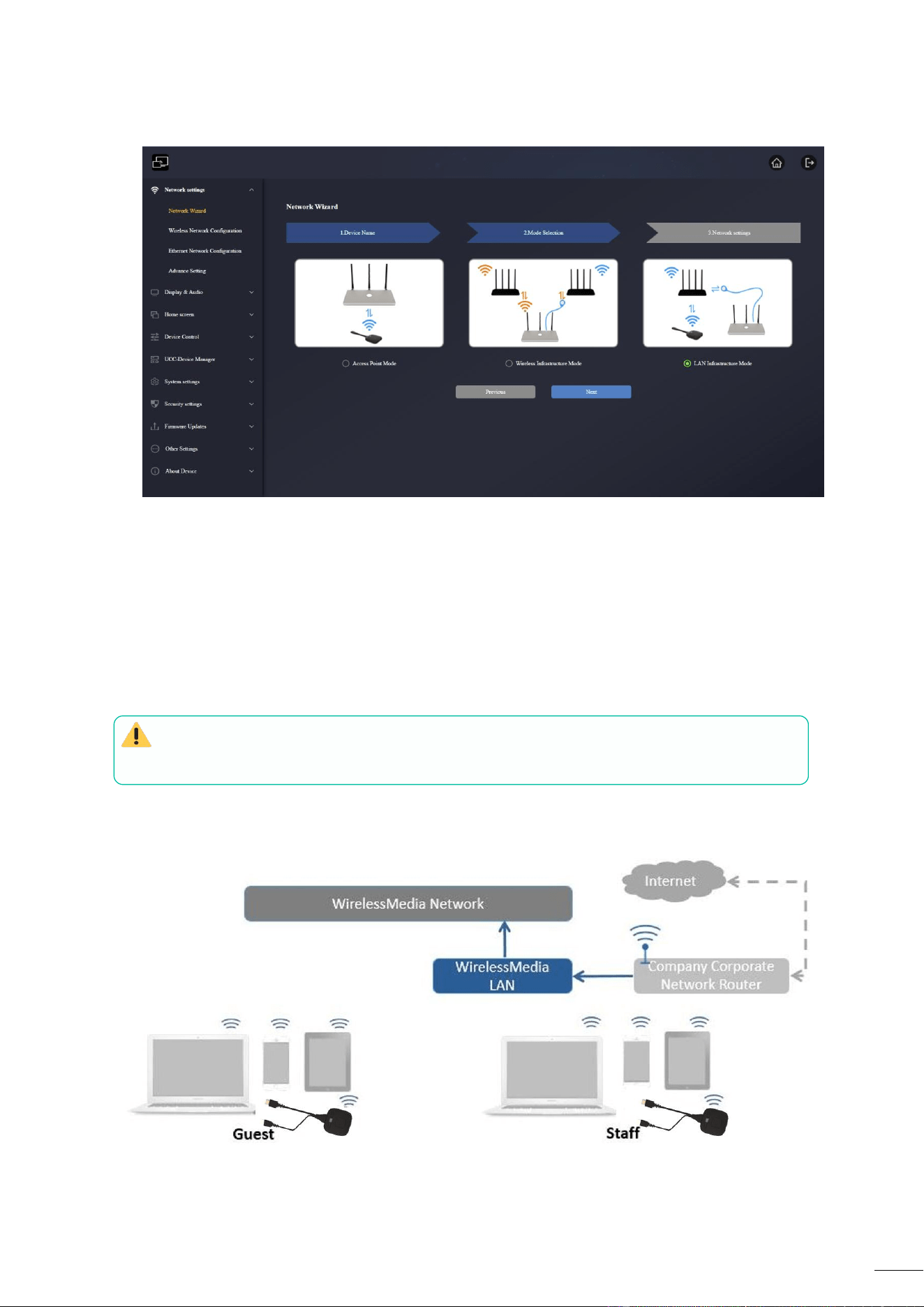
LAN Infrastructure Mode
WMT-H55
/
WMT-C55
will
be
automatically
paired
to
the
Staff
access
point,
and
not to
P35
base
unit.
In
this
configuration
the
built-in
WiFi
access
point
of
P35
is
disabled.
WMT-H55
/
WMT-C55
and
mobile
devices
can
connect
to
the
secured
wireless
access
point
ofthe
company
network.
The
P35
base
unit
will
be
connected
via
network
cable
to
the
wired
of
the
company
network.The
Staff
users
will
be
able
to
connect
to
their
usual
access
point
of
Company
network,
without the
need
to
change
the
WiFi
as
long
as
both
networks
are
on
the
same
range.
48
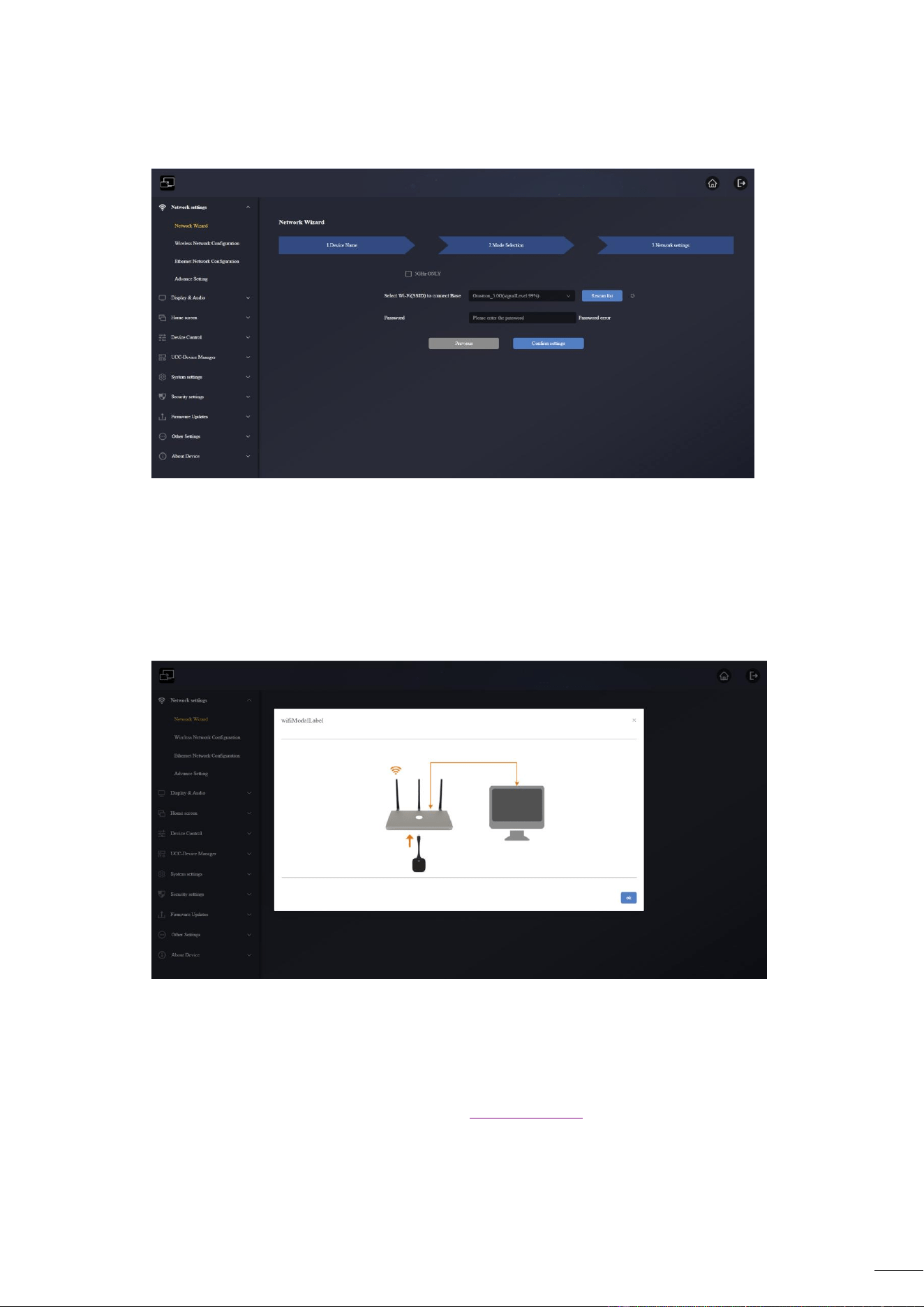
1. Click “Next” to enter the configuration of this the network mode.
Select Wi-Fi(SSID) to connect Base: Choose a network to connect to P35 for staff.
Password: enter password to connect the P35 to the staff network.
2. Click “Confirm settings” to finish configuration. Then pair transmitters with the P35.
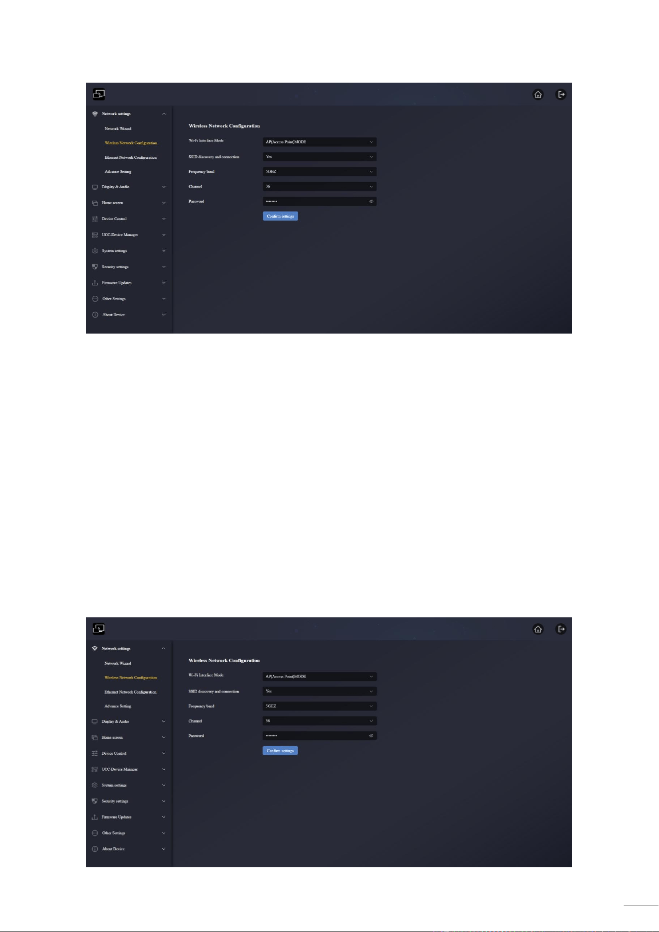
6.1.2 Wireless Network Configuration
For specific configuration of the three modes on this page, please refer to the operation of setting
the three network modes in the previous section "Network Wizard
".
49
Wi-Fi Interface Mode: AP(Access Point)MODE, STA(Station) MODE, OFF;
It can set the network mode directly on this page: Access Point Mode, Wireless Infrastructure
Mode or LAN Infrastructure Mode;
Which network mode is set on the network wizard page, this page will change accordingly;
similarly, after the mode is set on this page, the network wizard page will also change the network
mode accordingly.
6.1.2.1 AP(Access Point)MODE
When the Network Wizard is set to Access Point MODE, this page will be displayed in AP(Access
Point)MODE, you can directly set the options on this page.
50
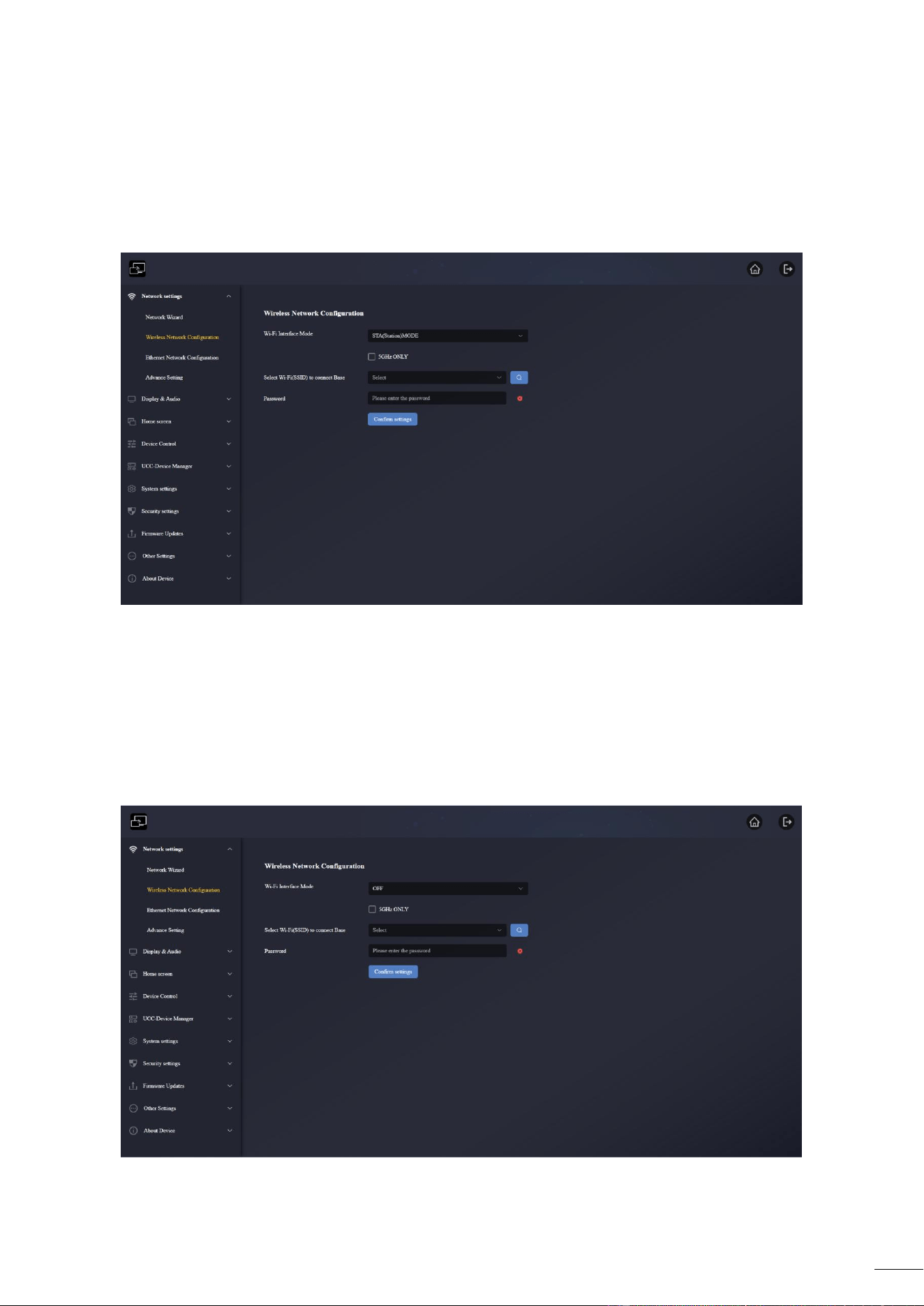
6.1.2.2 STA(Station)MODE
When the Network Wizard is set to Wireless Infrastructure Mode, this page will be displayed in
STA(Station)MODE, you can directly set the options on this page.
6.1.2.3 OFF
When the Network Wizard is set to LAN Infrastructure Mode, this page will be displayed in OFF,
you can directly set the options on this page.
51
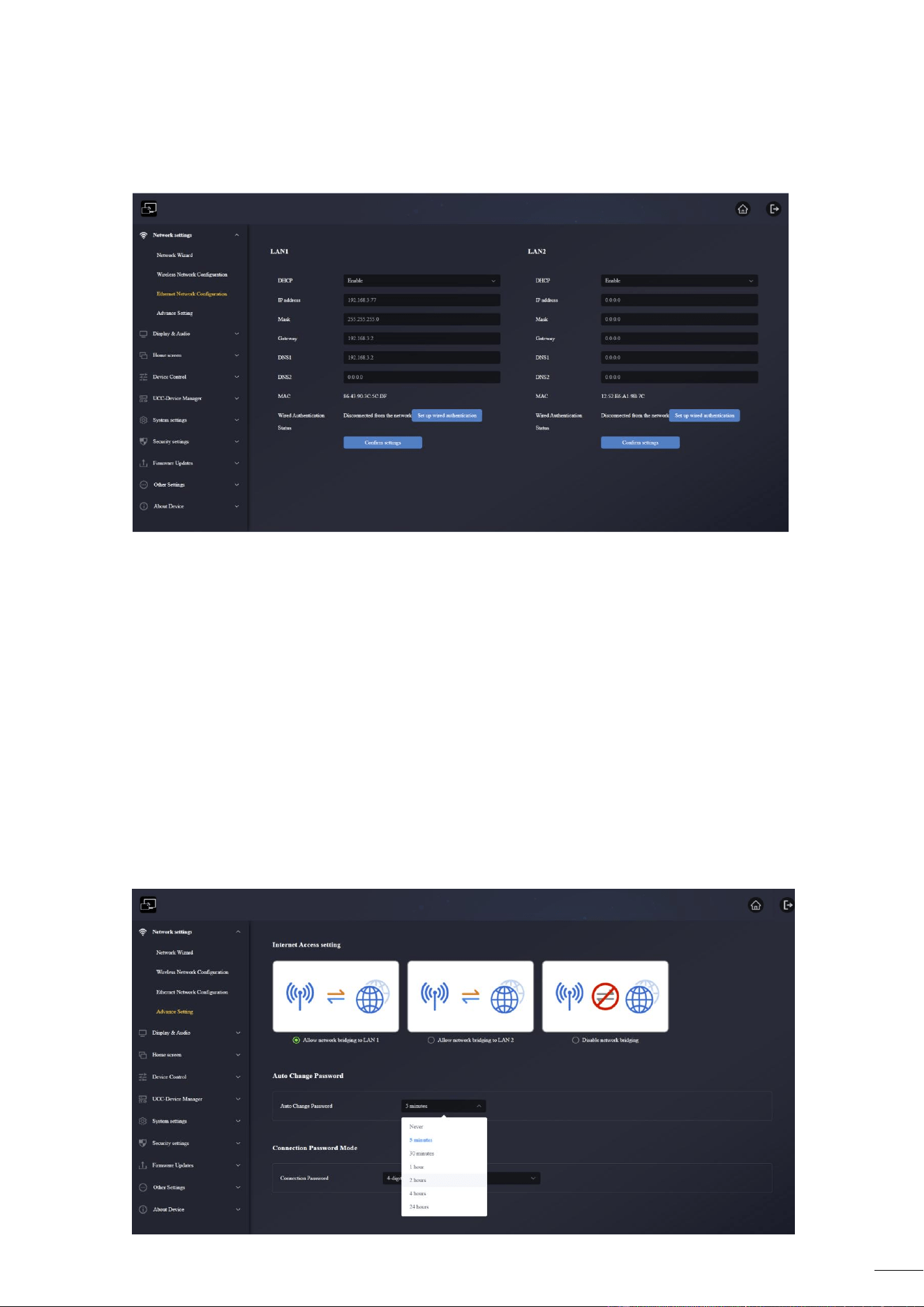
6.1.3 Ethernet Network Configuration
This section will let the user configure the wired LAN 1 and LAN2 settings.
DHCP: this parameter lets the user to enable the automatic assignment of IP address if a
DCHP server is present in the network. To configure a fixed IP address, first this parameter
should be disabled.
Mask: this parameter lets the user introduce the desired network mask.
Gateway: this parameter lets the user introduce the desired IP gateway.
DNS1-2: this parameter lets the user introduce the desired DNS servers.
Wired Authentication Status: Establish wired authentication (no authentication, EAP-TLS,
EAP-TTLS, PEAP).
6.1.4 Advance Setting
When the network mode is Access Point Mode, it can directly change the three ways the P35
connects to the Internet here.

52
Allow network bridging to LAN1: Allow the P35 to access the Internet through LAN port 1.
Allow network bridging to LAN2: Allow the P35 to access the Internet through LAN port 2.
Disable network bridging: Not allow the P35 to access the Internet through LAN port.
1. Auto Change Password
Never: never change WiFi password. (Even after POWER-OFF condition)
5 minutes: change WiFi password every 5 minutes.
30 minutes: change WiFi password every 30 minutes.
1 hour: change WiFi password every 1 hour.
2 hours: change WiFi password every 2 hours.
4 hours: change WiFi password every 4 hours.
24 hours: change WiFi password every 24 hours.
2. Connection Password Mode
4-digits password begining with 0000: The first 4 digits are fixed to 0, and the last 4 digits
are random numbers.
8-digits password: 8 digits are all random numbers
6.2 Display & Audio
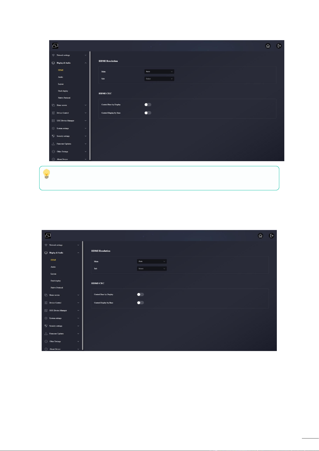
6.2.1 HDMI
6.2.1.1 HDMI Resolution
Select the resolution at HDMI output of base-unit.
Existing HDMI output resolution as below:
Main Sub
Auto ● Auto
3840x2160@60Hz ● 1920x1080@60Hz
3840x2160@50Hz ● 1280x720@60Hz
3840x2160@30Hz ● 1280x720@50Hz
1920x1080@60Hz
1920x1080@50Hz
1920x1080@30Hz
1280x720@60Hz
1280x720@50Hz
53
If the display only supports FULL HD, the 4K resolution will not be displayed on the
resolution list. The sub screen supports up to 1920*1080P
6.2.1.2 HDMI CEC
P35 support CEC function if the connected display support CEC function.
Control Base by the display
With this option, you can choose whether the connected P35 base unit automatically enters
standby mode or not as soon as the display is turned off.
o On: As soon as the display is turned off, the unit base P35 will also be auto turned off.
o
Off (Default): The display is turned off but the P35 will not be auto turned off.
54
Control Display by Base
With this option, you can choose whether the display automatically enters standby mode or
not as soon as the connected unit base P35 is turned off.
o ON: As soon as the P35 is turned off, the connected display will also auto turn off.
o
OFF (Default): Display will not automatically turn off when P35 is turned off.
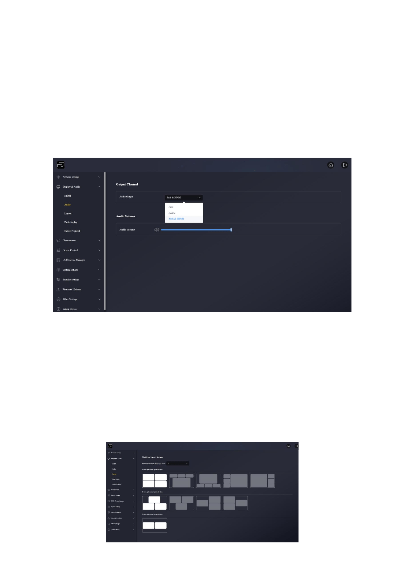
6.2.2 Audio
Allows the user to choose which sound source is routed to audio output.
1. Audio output:
Jack: output only 3.5mm mini-jack audio.
HDMI: output only HDMI audio.
Jack&HDMI (Default): output Jack & HDMI audio.
2. Audio volume: volume can be selected from 0 to 100.
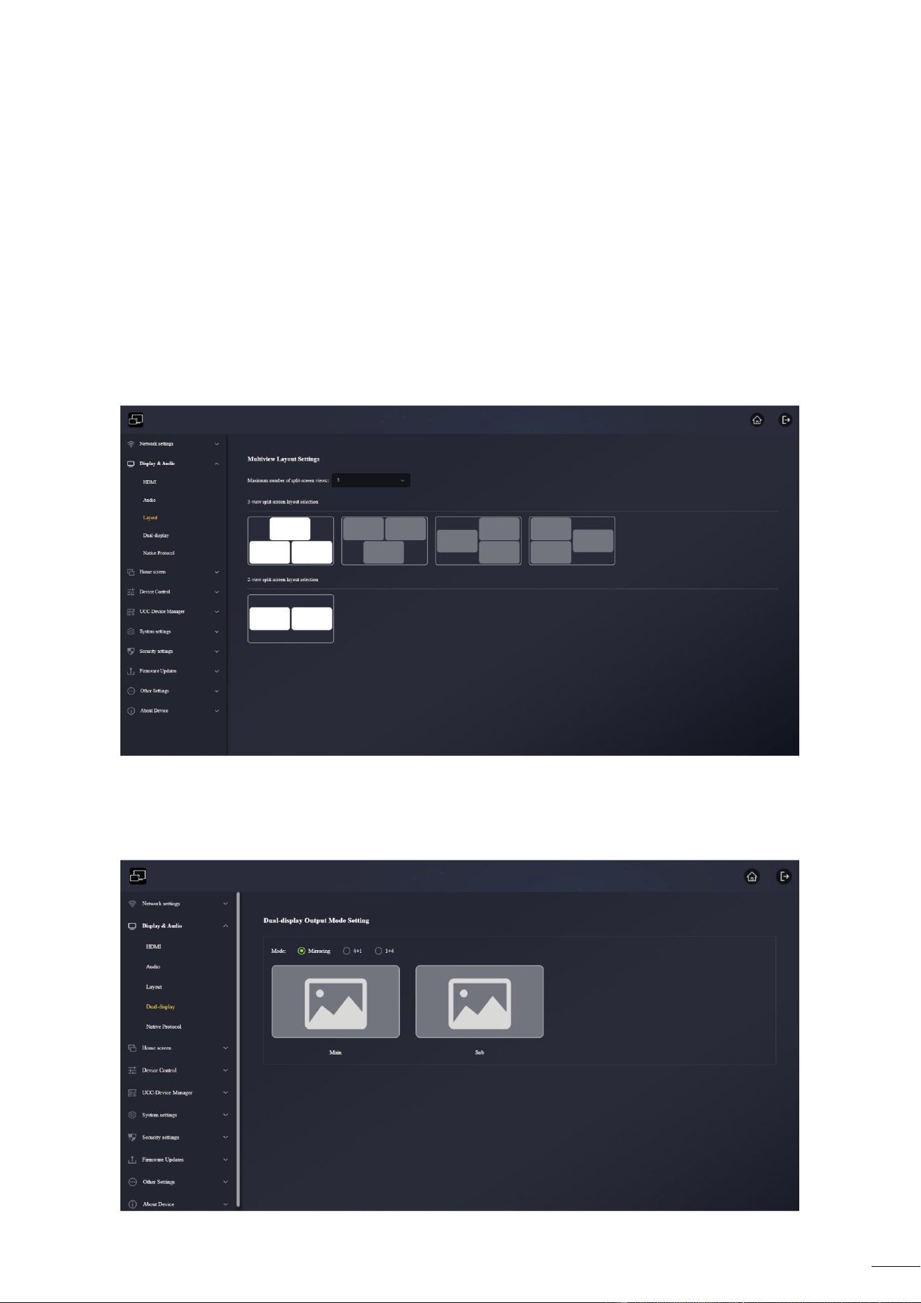
6.2.3 Layout
Allows various fixed window layout presets to display participants in the main screen. Four the
most can be performed simultaneously on one screen.
55
Maximum number of split-screen views: 1, 2, 3, 4
It can manually select the number of screens allowed to be presented as needed. If it selects 4, it
can cast a maximum of 4 screens. It can select a 4-split screen layout in the layout selection; if it
selects 3, it can only cast a maximum of 3 screens. It is the same meaning of selecting 1 and
selecting 2.
Example:
Select the maximum number of split-screen views is 3, the screen display is shown as below photo.
It can choose a 3-split screen layout in the layout selection.
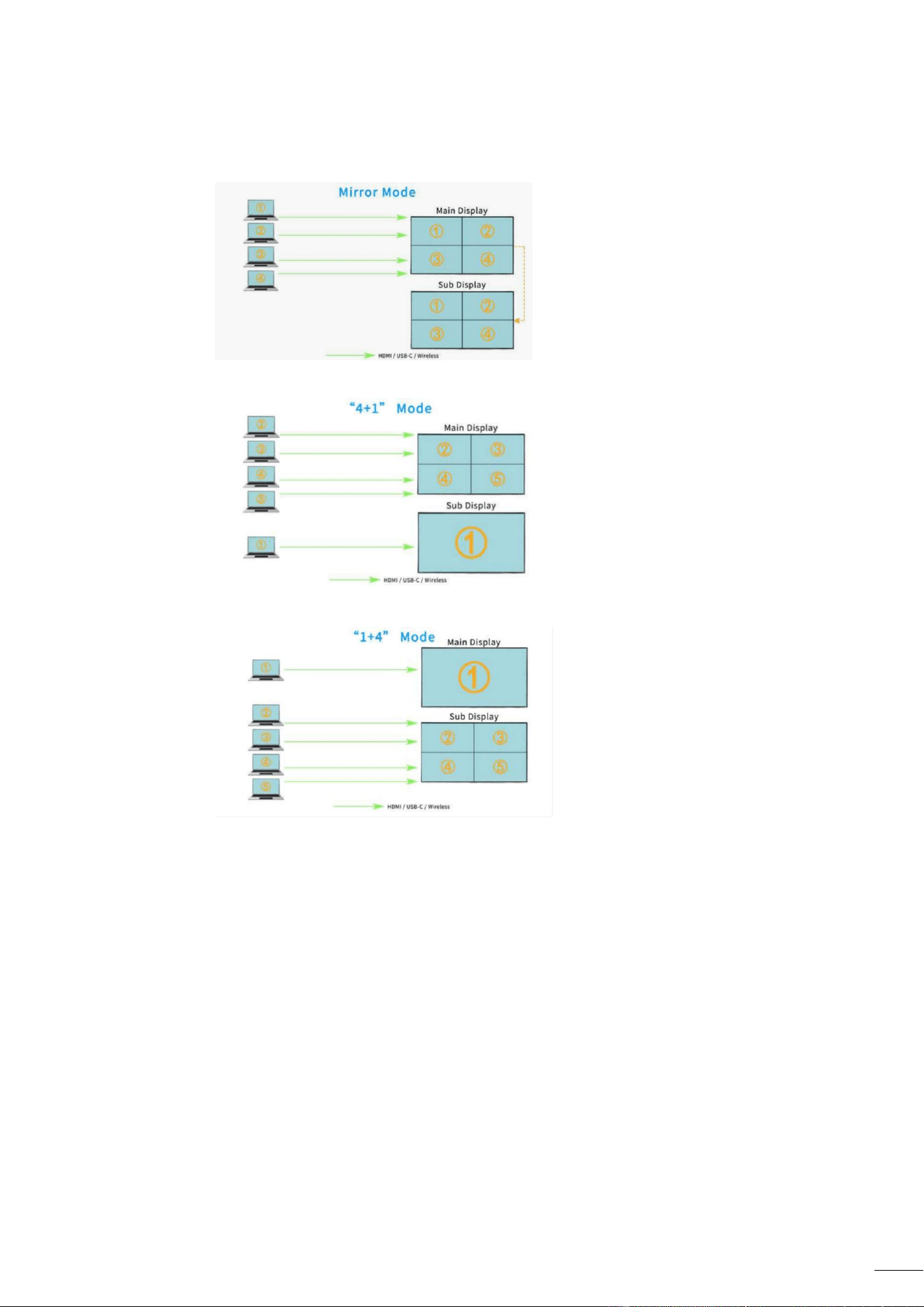
6.2.4 Dual-display
P35 can use two screen to display and can cast up to 5 images at the same time.
56
Mode:
Mirroring: Main screen and sub screen display the same cast image
4+1: Main screen can cast 4 images, sub screen can cast 1 image
1+4: Main screen can cast 1 image, sub screen can cast 4 images
Note:
In mode 4+1 or 1+4, the first cast screen is fixed even though the 6 cast source comes.
Example:
In 1+4 mode, there are several sources A/B/C/D/E/F for projection. The display logic is as follows
Main Sub
A home screen
A B
A B/C
A B/C/D
A B/C/D/E
A C/D/E/F
57
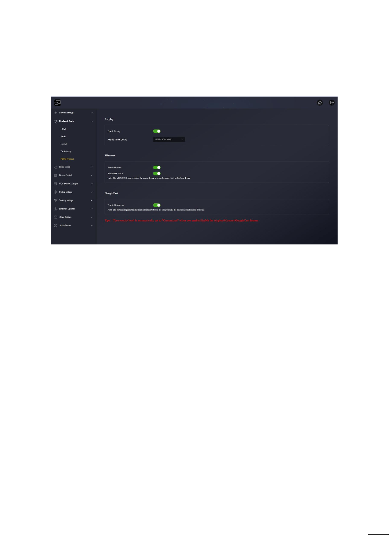
6.2.5 Native Protocol
Enabling/disabling third-party protocol, it will adjust the security level to a customized level.
6.2.5.1 Airplay
Airplay switch: enabled by default;
Turn on the Airplay switch, it can perform airplay screencasting through Mac, iPhone, and PAD.
Turn off the Airplay switch, it can not perform Airplay screencasting.
Airplay screen projection resolution:
>> High (1920*1080)
>> Medium(1600*900)
>> Low (1280*720)
>> 4k (3840*2160)
Note:
The higher the resolution, the clearer it is, but it will also bring greater delay.

58
6.2.5.2 Miracast
Miracast switch: enabled by default;
Miracast uses the P2P protocol by default, and the maximum supported resolution is 1080p. In
this mode, the computer and the base unit do not need to be on the same network. It only needs
to press the Windows+K keys to enable the Miracast function. In the searched miracast device
Find the P35 device and click the link to start screencasting;
Miracast MICE protocol switch: off by default
The MS-MICE protocol is an extension of the P2P protocol. To start this protocol, the PC and P35
need to be in the same LAN. Searching device still uses the P2P protocol, but when transmitting
video streams, it uses the LAN. There is no difference in usage from when the MS-MICE protocol is
not turned on.
Note:
MS-MICE functionality requires the source device to be on the same LAN as this device.
6.2.5.3 GoogleCast
Google Cast switch: enabled by default
Note: This protocol requires that the time difference between the computer and the base unit
does not exceed 24 hours.
6.3 Home screen
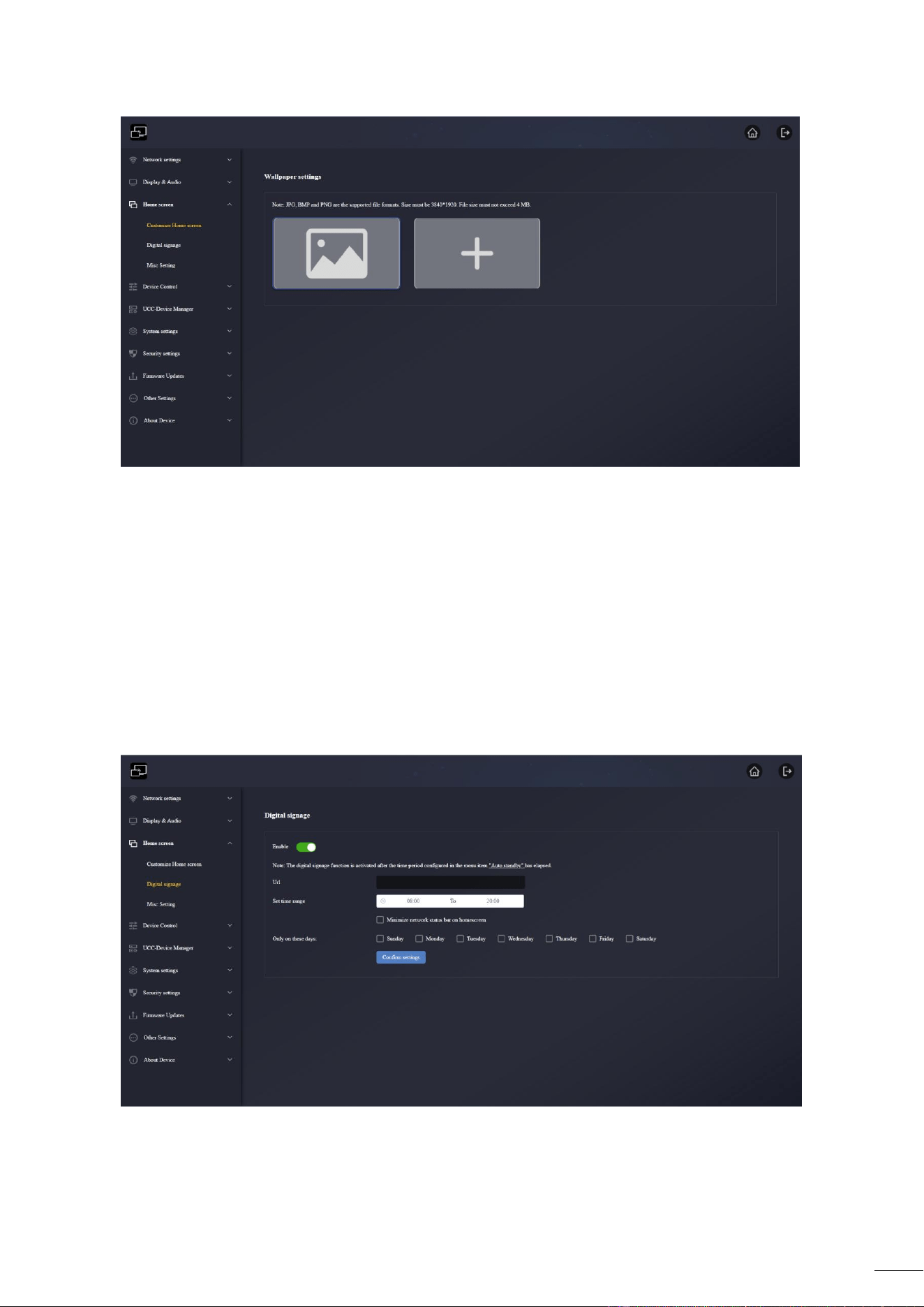
6.3.1 Customize Home screen
The home screen background can be customized. Click + to add a local image as the home screen
background image.
Note:
Currently supported image formats are: JPG/BMP/PNG, the maximum resolution is 3840*2160,
and the file size is within 4MB.
59
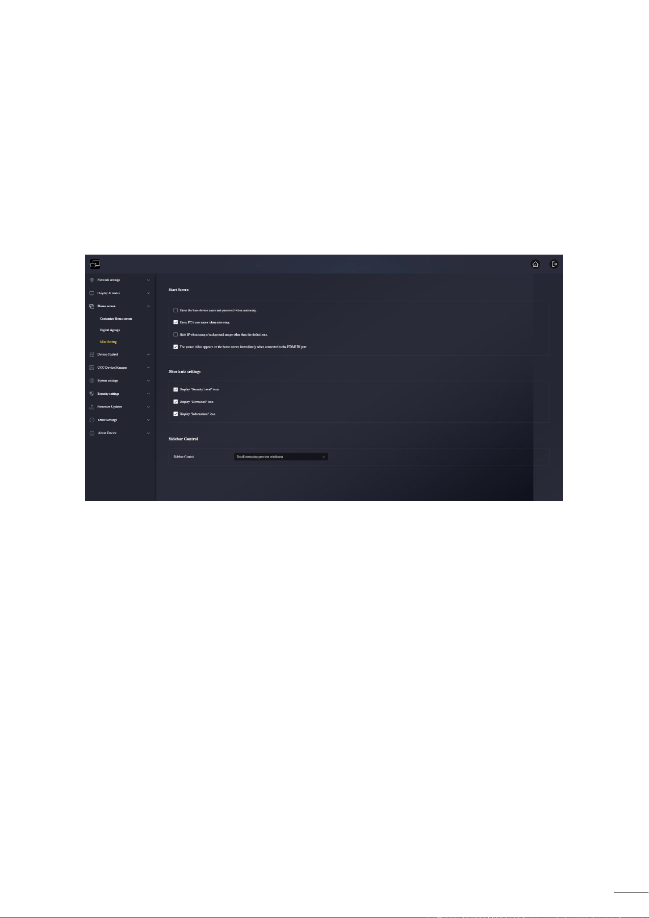
6.3.2 Digital signage
Switch is off by default
This function can display the web page information you want when the base unit is standby
Note:
Digital signage functionality will activate when ready for "auto standby".
URL: Enter the required URL.
Set time range: Set a time period. During this time period, the monitor will be standby and display
the web page information of the URL that set above.
60
Only on these days: it can set the date you want to display (Monday to Sunday).
It can directly click "Auto Standby" in the prompt on this page to jump to the auto standby page
for settings.If the current time is within the set time period, press the power key on the P35
device to enter the digital signage page. Press the key again to exit and return to the main page.
6.3.3 Misc Setting
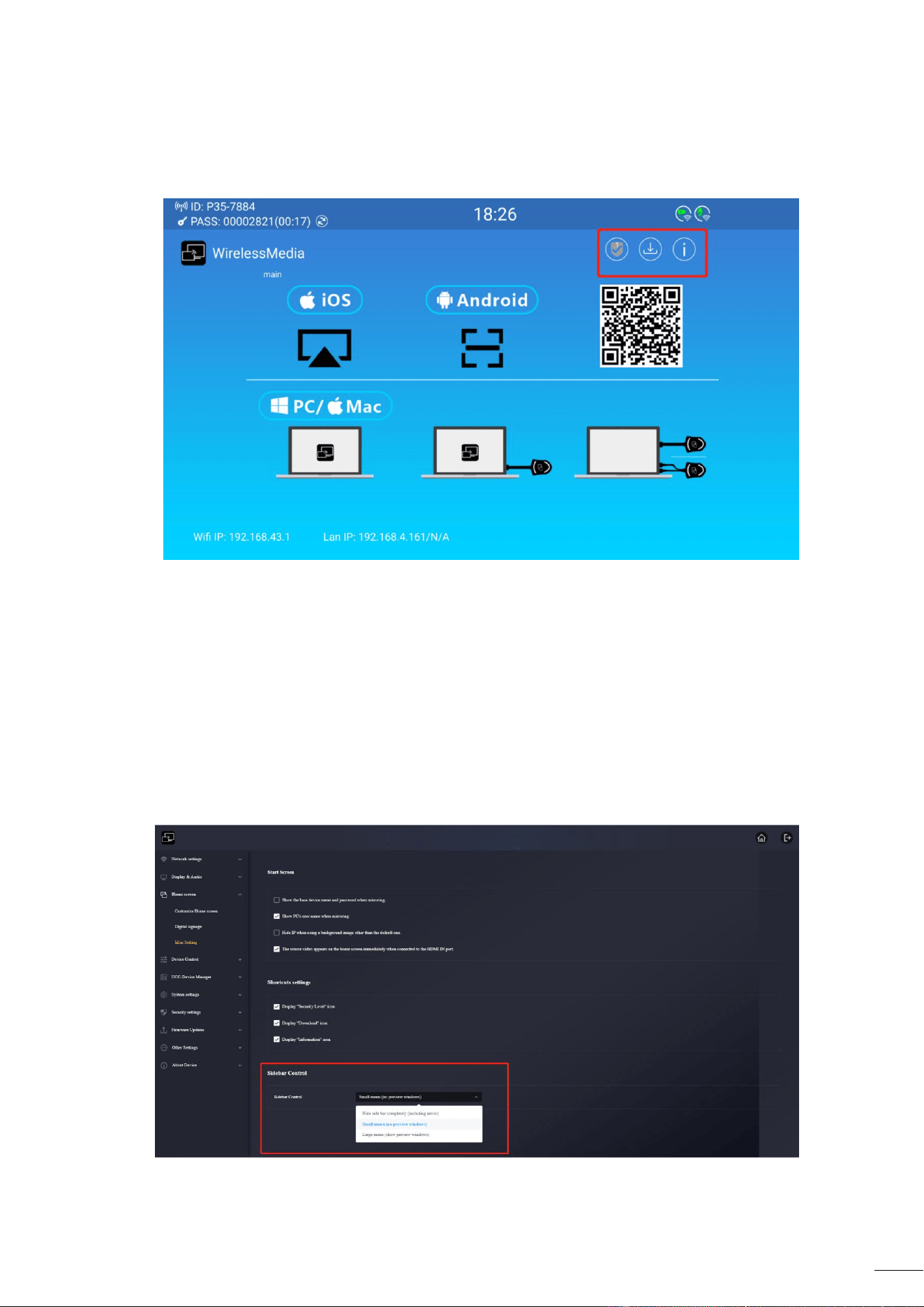
6.3.3.1 Start Screen
Show the base device name and password when mirroring: When this option is ticked, the
P35's device ID and password will not disappear when mirroring.
Show PC’s user name when mirroring: When this option is ticked, the PC username will be
displayed when casting the screen.
Hide IP when using a background image other than the default one: When this option is
ticked, the base device wifi IP and LAN IP will not displayed if the background image is not
the default one.
The source video appears on the home screen immediately when connected to the HDMI
IN port: When this option is ticked, it will cast the screen automatically if an HDMI source is
plugged into the P35's HDMI IN port.
6.3.3.2 Shortcuts settings
Display “Security Level” icon: The Security Level icon will be displayed on the home screen
when ticked. If not, it won’t be displayed.
Display “Download” icon: The Download icon will be displayed on the home screen when
ticked. If not, it won’t be displayed.
61
Display “Information” icon: The Information icon will be displayed on the home screen
when ticked. If not, it won’t be displayed.
6.3.3.3 Sidebar Control
Hide side bar completely(including arrow): When choose this item, the side bar won’t be
shown on the home screen.
Small menu(no preview windows): When choose this item, the side bar will be shown as
small menu(including whiteboard, annotation, information icon) on the home screen.
Large menu(show preview windows): When choose this item, the side bar will be shown as
large menu as well as the preview window will be displayed on the home screen.
62
6.4 Device Control
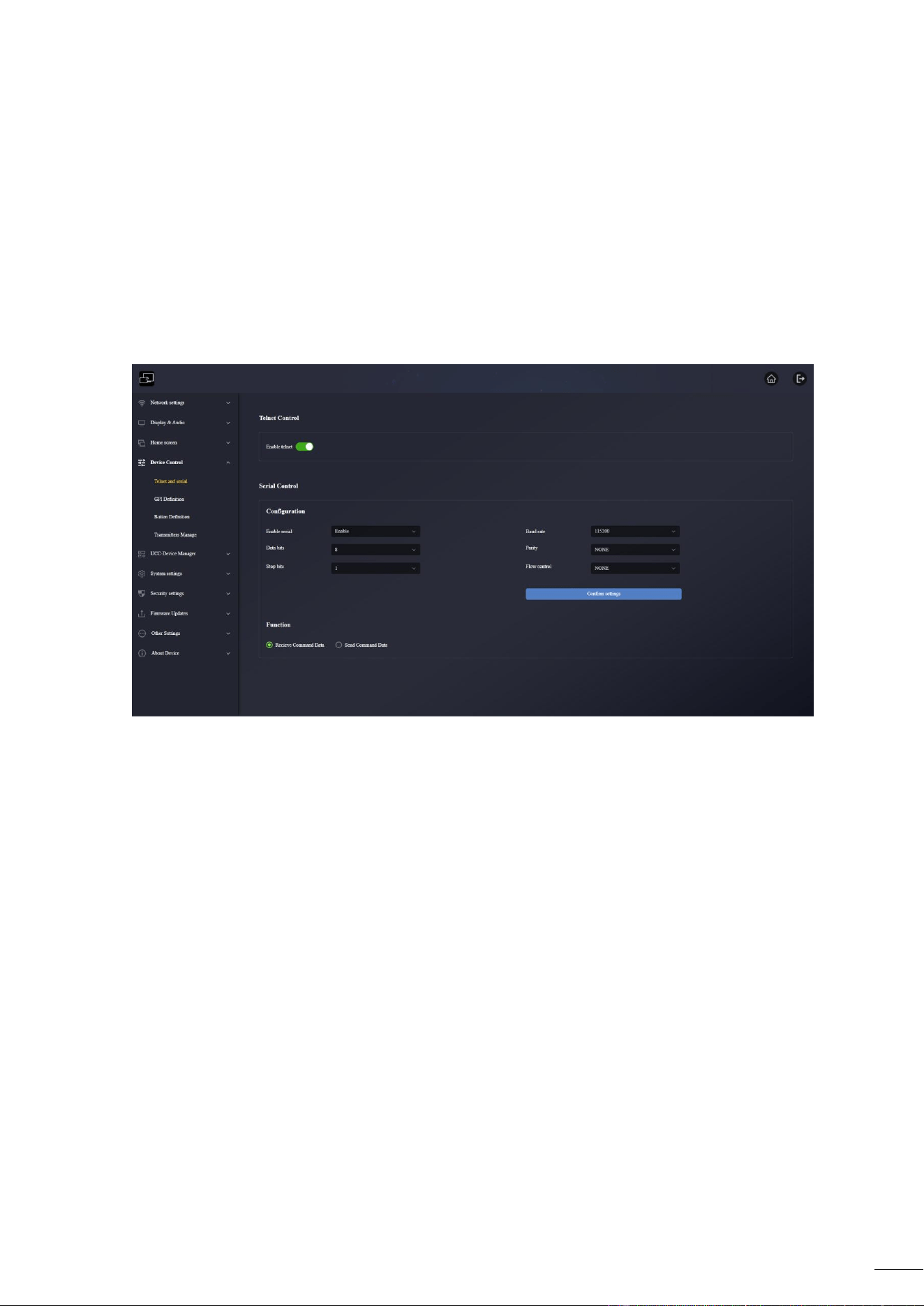
6.4.1 Telnet and serial
It allows users to configure telnet commands and RS-232 commands to control the P35.
Please contact the supplier for the control command table. In addition, RS232 also supports
sending simple commands, such as power on and off, controlling cascaded devices, and realizing
simple central control functions.
6.4.1.1 Telnet Control
Enable telnet: enabled by default.
When it is enable, the telnet command can control the device.
When it is not enable, it won’t be able to use the telnet command to control the P35.
Telnet communication via TCP commands, enter the current P35 IP address and port 23.
For commands that contain multiple words, spaces are required between each word.
Commands are not case sensitive.
6.4.1.2 Serial Control
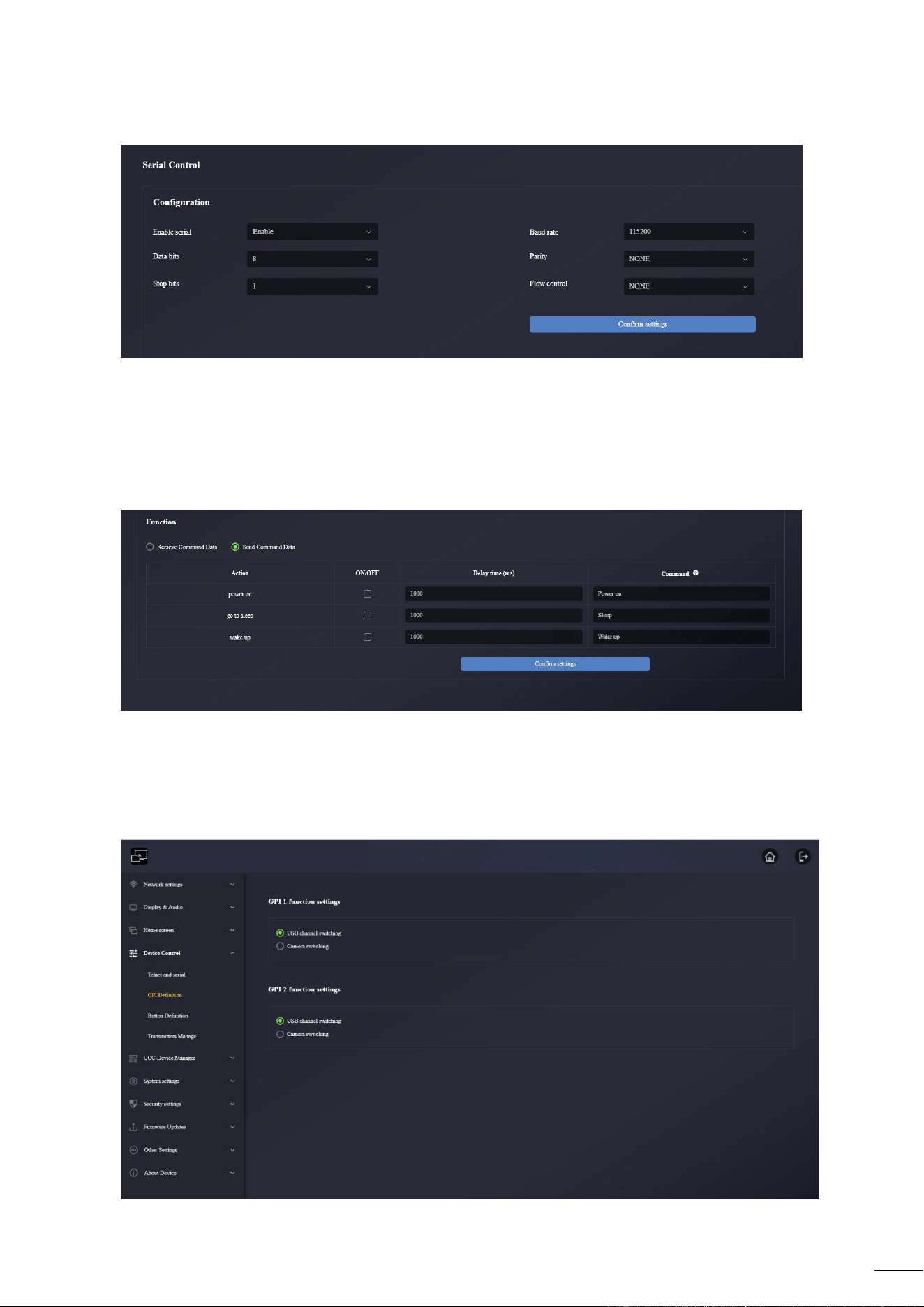
The serial port function is enabled by default. When it is disabled, RS-232 commands cannot be
used to control the P35.
63
For the first use, Set the baud rate, data, parity bit, stop bit, and flow control as needed.
6.4.1.3 Function
Receive Command Data: Base unit P35 can reveive the command and be controlled
Send Command Data: Base unit P35 can send the command out to control other device
proactively
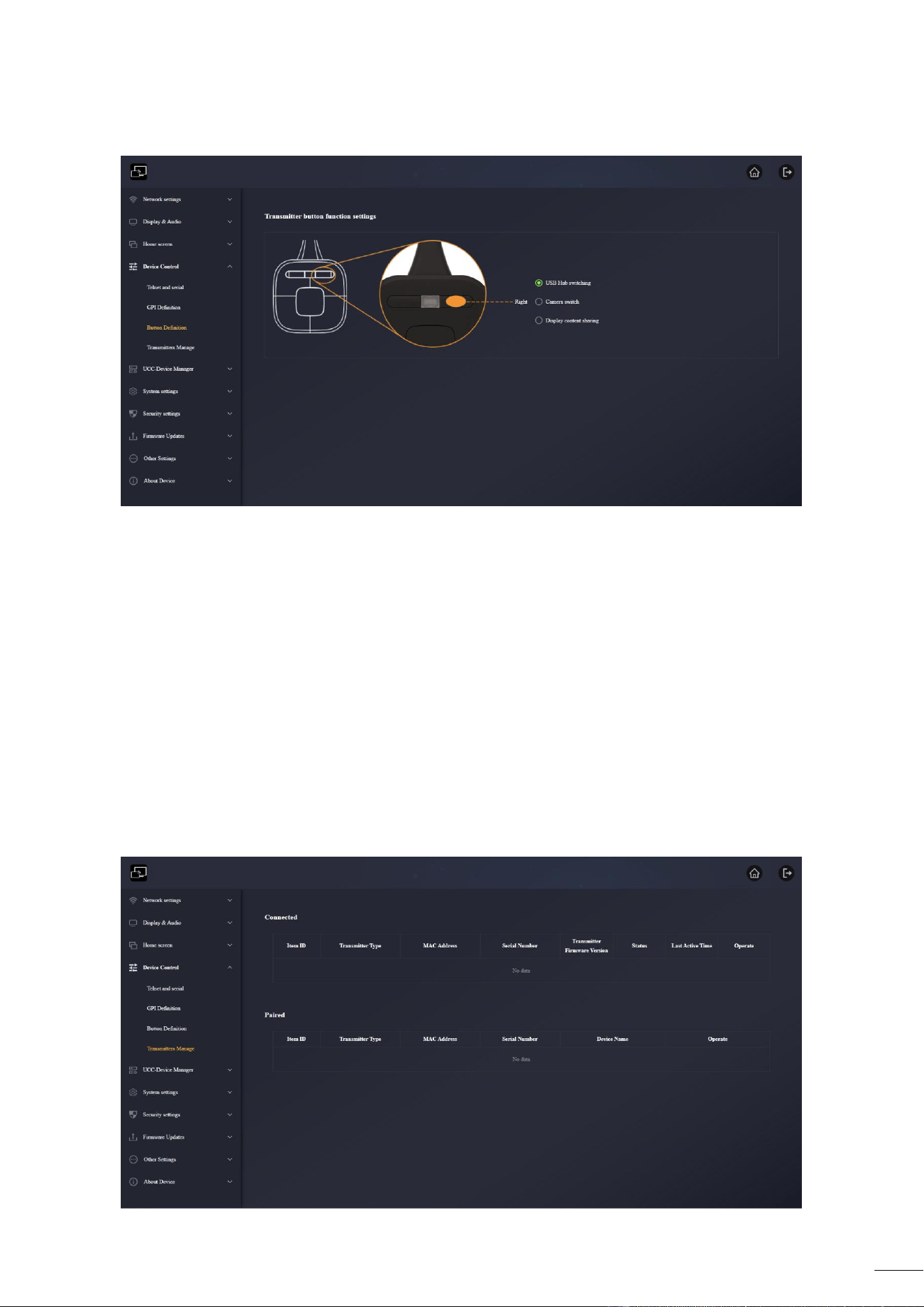
6.4.2 GPI Definition
Two GPI inputs, the maximum power frequency supports 5V input, the function of the input port
can be customized
64
6.4.3 Button Definition
USB Hub switching: When press the button, the function will be change between USB-B and
WirelessMedia to make the connection.
Camera switch: When press the button, it can switch different camera to use.
Display content sharing: This function will capture the content on the selected screen (main
screen or sub screen) and create a window for the video conferencing software to do the
remote sharing.
Note:
When the mouse is placed on the function options, a prompt for the function will pop up.
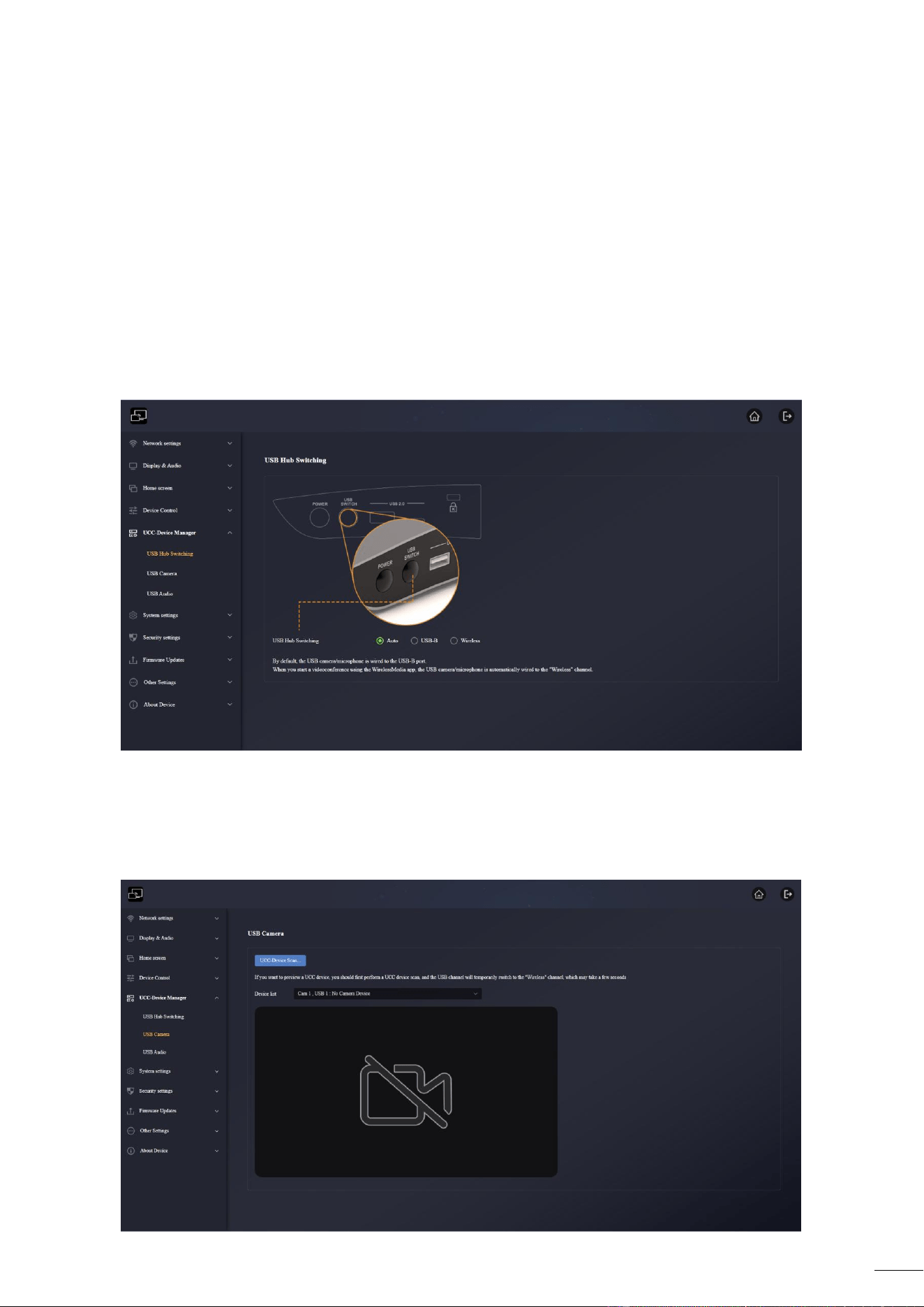
6.4.4 Transmitters Manage
65
Connected: Display the transmitters being connected to P35 and show the corresponding
transmitters information.
Paired: Display the transmitters successfully paired with P35 and show the corresponding
transmitters information.
6.5 UCC-Device Manager
6.5.1 USB Hub switching
It can switch the mode Auto/USB-B/Wireless by press the button on P35 base unit.
6.5.2 USB Camera
It allows users to select and preview the current USB camera device. When multiple cameras are
connected, the camera that wants to be used can be switched here.
66
UCC-Device Scan: After clicking, the connected camera device will be scanned.
Device list: Display the transmitters successfully paired with P35 and show the corresponding
transmitters information.
Note:
If wants to preview a UCC-device, it should first use UCC-device scan function, the USB channel
will temporarily switch to the "Wireless" mode, this may take a few seconds
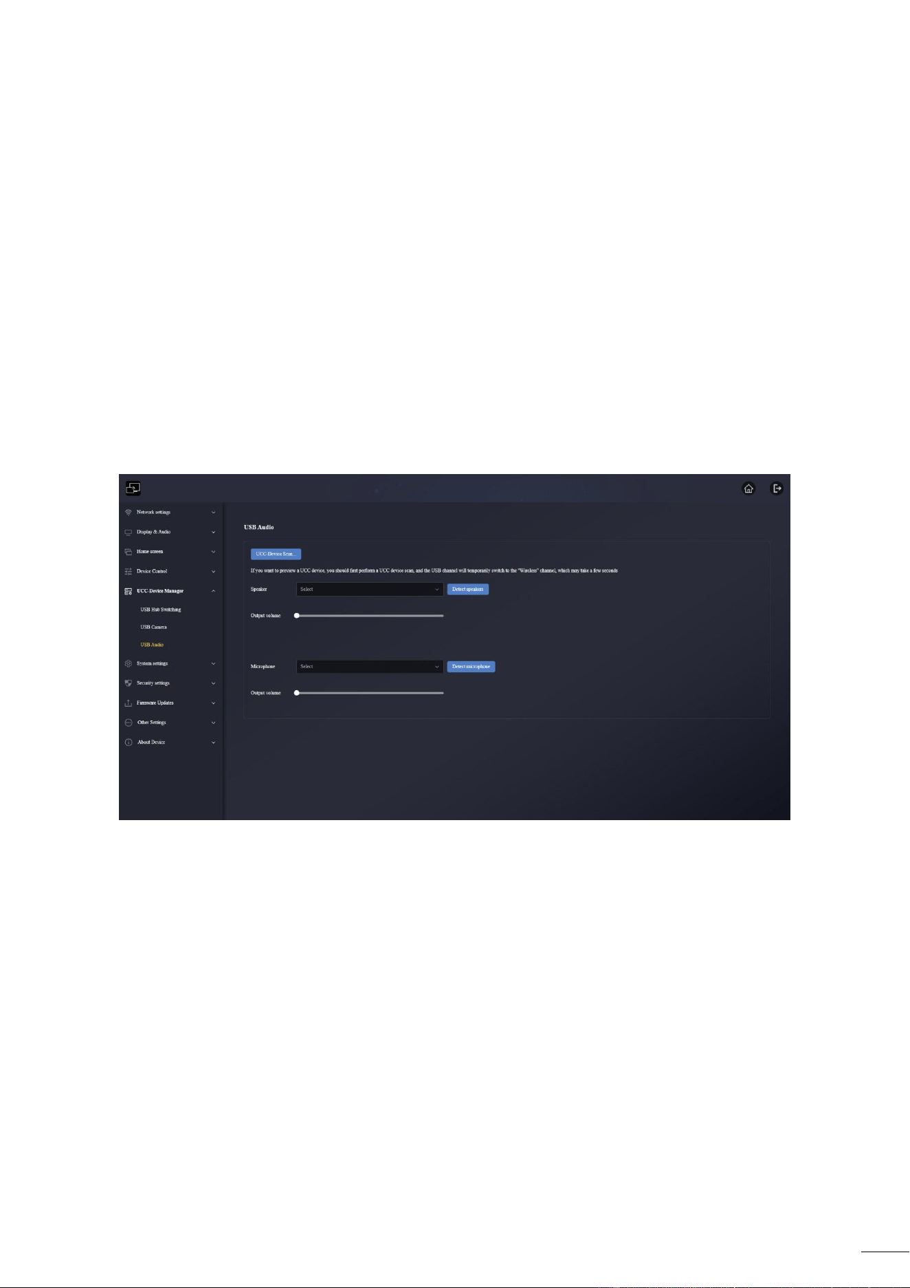
6.5.3 USB Audio
It allows users to select and preview the current USB audio device. When multiple microphones or
speakers are connected, they can switch the microphone or speaker to be used here.
UCC-Device Scan: After clicking, the connected audio device will be scanned.
Detect speakers: Click this button to test whether the audio device outputs sound normally.
Click button again it will cancel.
Detect microphone: Click this button to test whether the audio device inputs sound normally.
Click button again it will cancel.
Note:
If wants to preview a UCC-device, it should first use UCC-device scan function, the USB channel
will temporarily switch to the "Wireless" mode, this may take a few seconds
67
6.6 System settings
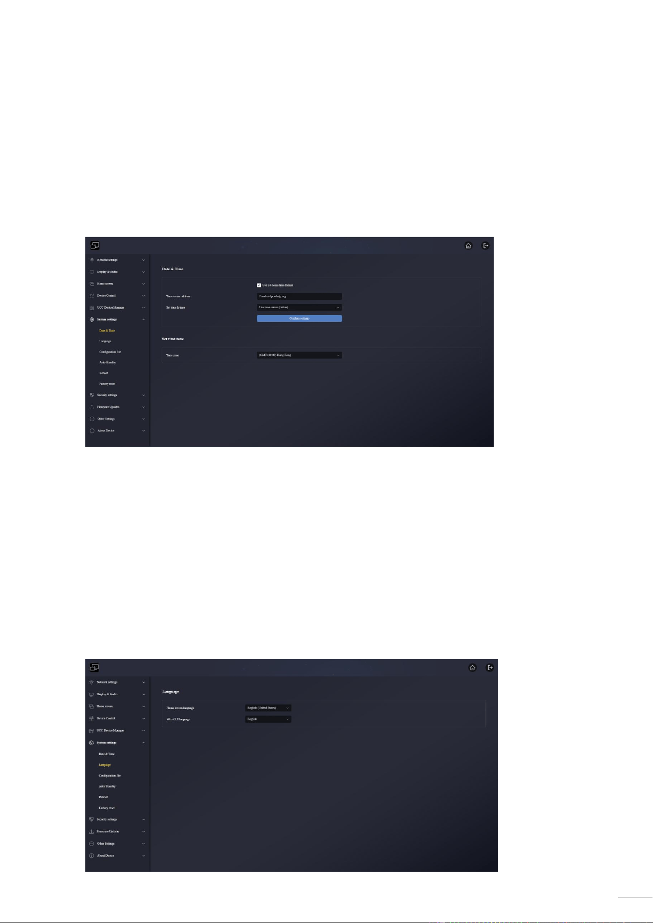
6.6.1 Date & Time
Use 24-hours time format: If ticked, the time will be displayed in 24-hour time format. If not
ticked, the time will be displayed in 12-hour format.
Time Server address: 2.android.pool.ntp.org
Set date & time:
Use time server(online): Check and use an NTP time server to provide time as system time.
OFF: It can set the date and time manually after turning off the network time
Time zone: Click the "Time Zone" option to drop down and select the required time zone.
6.6.2 Language
It allow users to select the home screen and web page display language
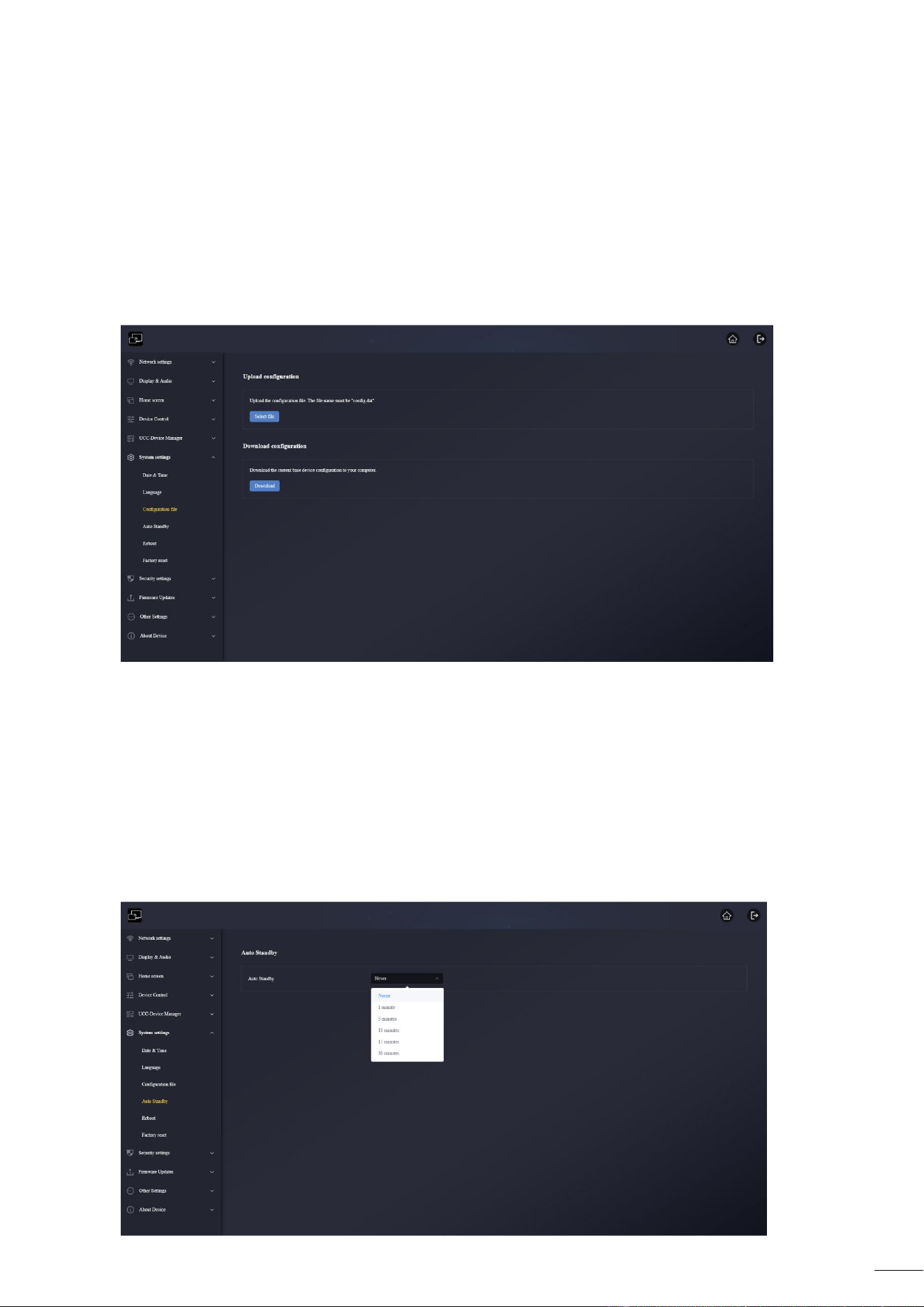
68
Home screen language: It can select the language display on home screen here.
Web-GUI language: It can select the language display on Web-GUI here.
6.6.3 Configuration file
A profile is a downloadable preset that will save all set configuration parameters so that they can
be loaded onto other devices.
Upload configuration: The file name must be "config.dat" when upload the file.
Download configuration: It can download the current P35 configuration to the computer.
6.6.4 Auto Standby
When Auto Standby mode is activated, the P35 base unit will automatically switch to power
saving mode. In standby mode, the green LED on top of the P35 base unit flashes and the HDMI
output is off.
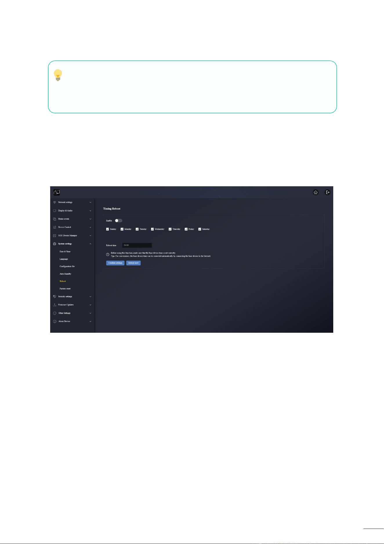
69
6.6.5 Reboot
It allows users to perform scheduled restart and routines for a given week
Timing Reboot: The scheduled restart time of the P35 base unit can be set, and the days that
need to be restarted can be selected from Monday to Sunday.
Reboot time: It can set the time to restart manually here.
Note:
Whether scheduled restart is enabled or not, it can click Restart now icon and the P35 base unit
will restart at once.
6.6.6 Factory reset
It allow users to perform a factory reset to restore device default settings.
deactivates
standby
mode
as
well.
When
a
WMT-H55
/
WMT-C55
is
plugged
in
and
connected,
or
a
mobile
device
is connected,Standby
is
deactivated.Movement
of
mouse
at
USB-input
at
P35
base
unit
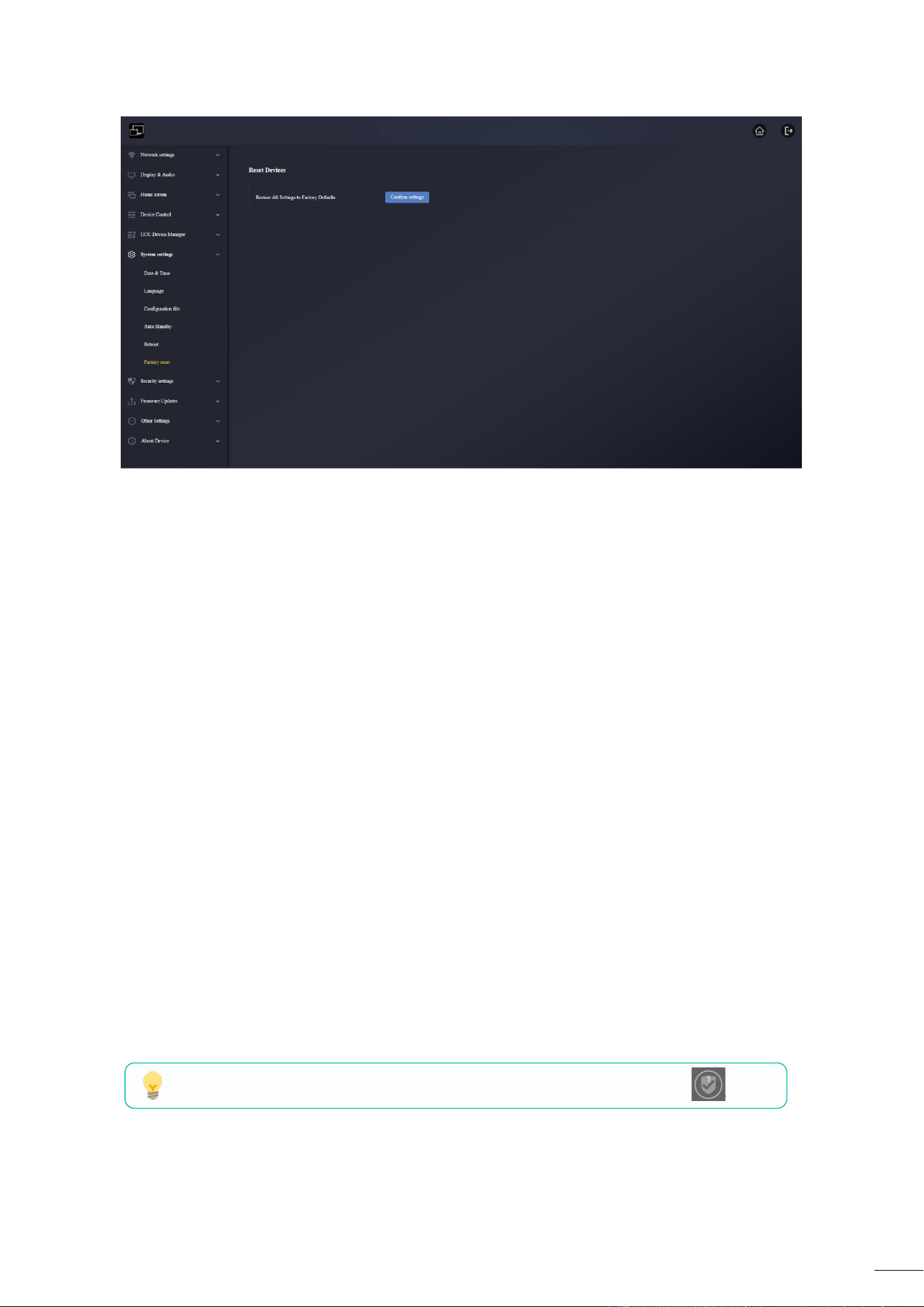
70
6.7 Security settings
6.7.1 Security Level
Based on user requirements, three different security levels can be set to satisfy different security
requirements.Click on the corresponding entry in the menu to adjust the respective security
features. The default setting is level 1.
Level 1: normal safety;
Keeps the security in normal and daily usage for any organization, such like classroom, regular
meeting room etc.
Level 2: higher security;
Provides increased security for companies, organizations, government agencies, etc., through
powerful encryption of audio and video data; other security features include limiting the
transmission of "AirPlay" by introducing a password.
Level 3: highest security;
It is used for strict security requirements of companies, organizations, authorities, banks.This level
contains all “Level 2” security measures and in addition, all mobile applications as well as the web
settings GUI will be blocked. In addition, the downgrade of the firmware will not be possible.
The security level will be displayed in the Home Screen clicking on the icon
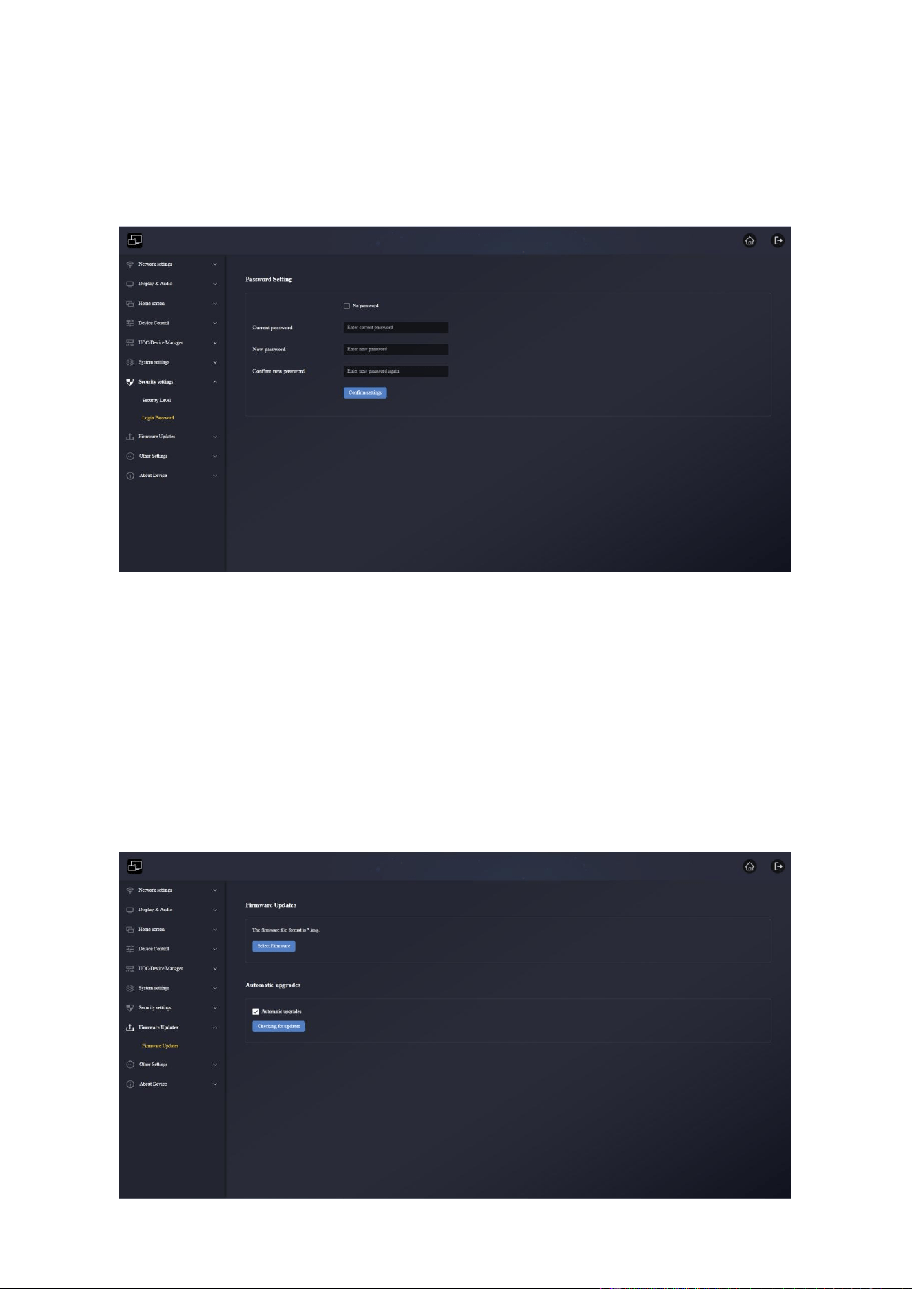
71
6.7.2 Login Password
It allows the user to change their password to enter the web settings GUI.
The default password is "admin"
No password: When ticked here, it can log in directly to the web and no need the password
to enter.
Current password: Enter the current login password of the base unit.
New password: Enter the new password that wants to set.
Confirm new password: Enter the new password again.
6.8 Firmware Updates
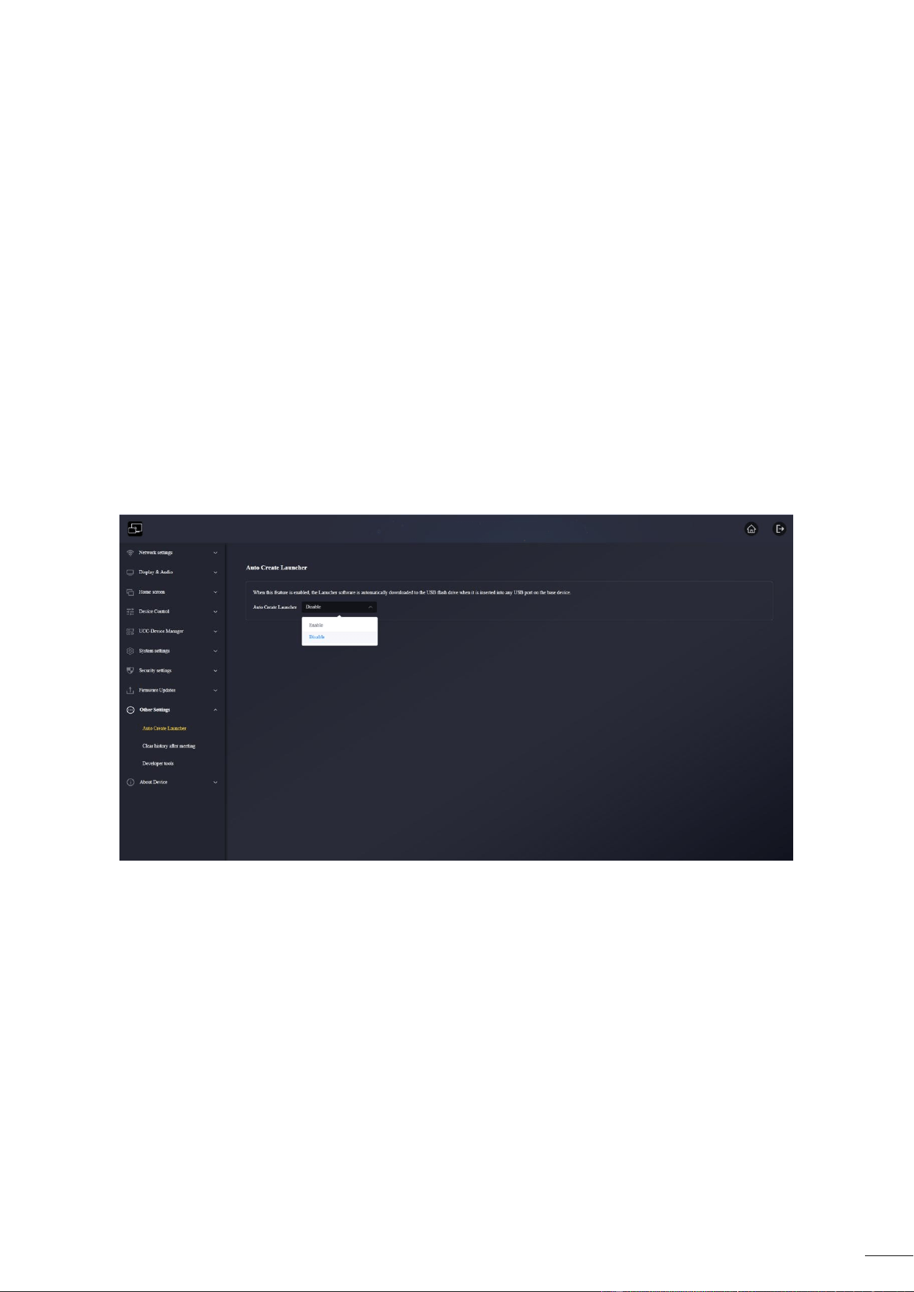
72
Firmware Updates: Users can upload local update files to upgrade P35. The firmware file
format is *.img.
Automatic upgrades: When ticked, it will automatically detect the new system and update
in the early morning. If not ticked, it can manually click the Check for Updates button to
detect updates manually.
6.9 Other Settings
6.9.1 Auto Create Launcher
After enabling this function, when a USB flash drive is inserted into any USB port of the base unit,
the Launcher software will be automatically downloaded to the USB flash drive.
Enable: When the USB flash drive is connected to the base unit, the Windows and mac
applications WirelessMedia, user manual, and Android apk will be automatically copied to
the USB storage.
Disable: When the USB flash drive is connected to the base unit, the Windows and mac
applications WirelessMedia, user manual, and Android apk won’t be automatically copied to
the USB storage.
Note:
If necessary, it also can click the download button manually on the home screen to download and
save to the USB flash driver finally.
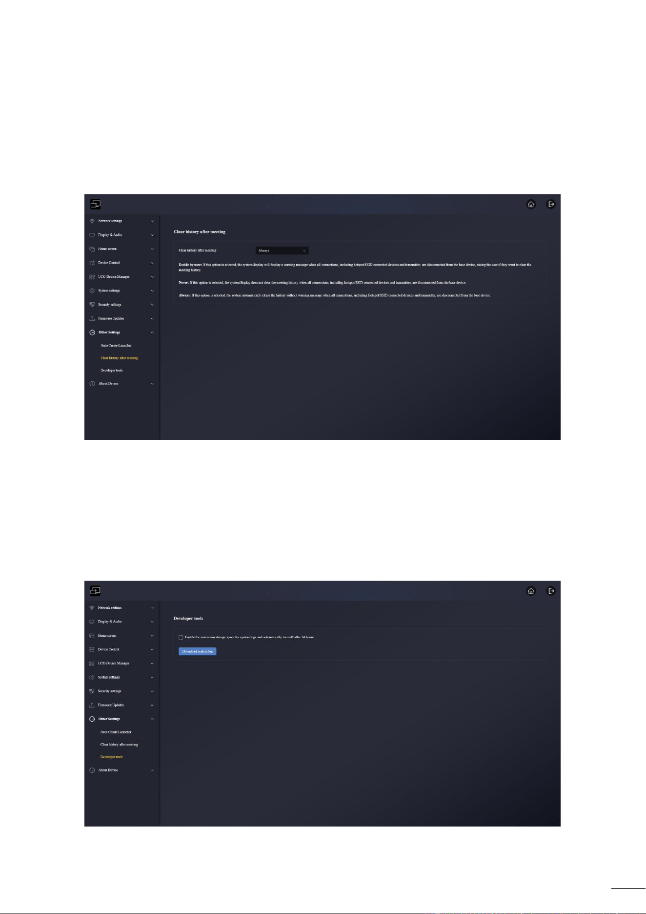
73
6.9.2 Clear history after meeting
The pictures, videos, and music from the screen mirroring device will be stored in the memory of
the Base unit. At the end of the meeting, when removing the transmitter from the laptop/PC,
here is an option to clear this memory.
6.9.3 Developer tools
Used to capture the log when a problem occurs. Click Download System Log on icon, and the
system will automatically start downloading the log file.
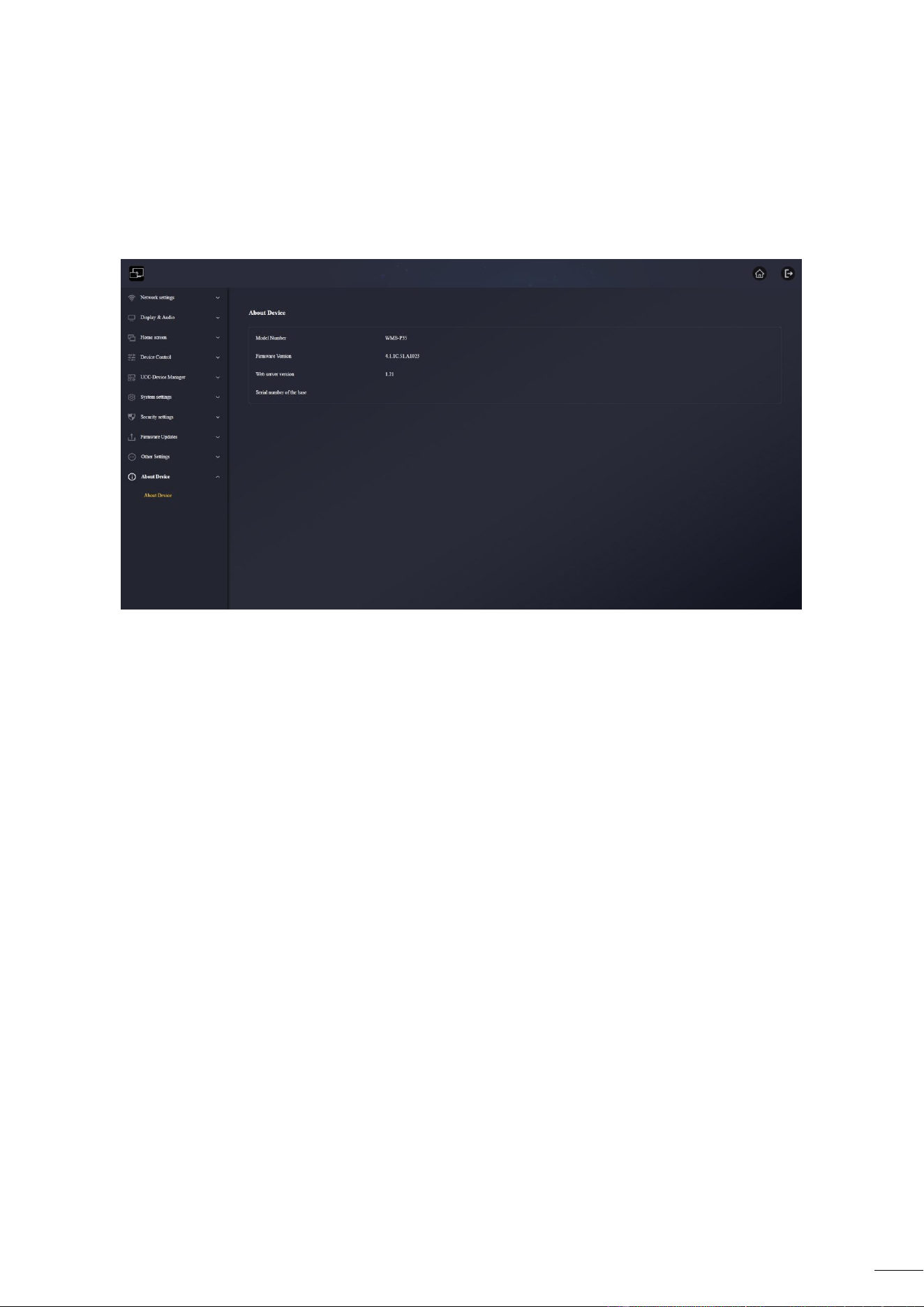
74
6.10 About Device
The information includes device Model Number, Firmware Version, Web server version, Serial
number of the base.
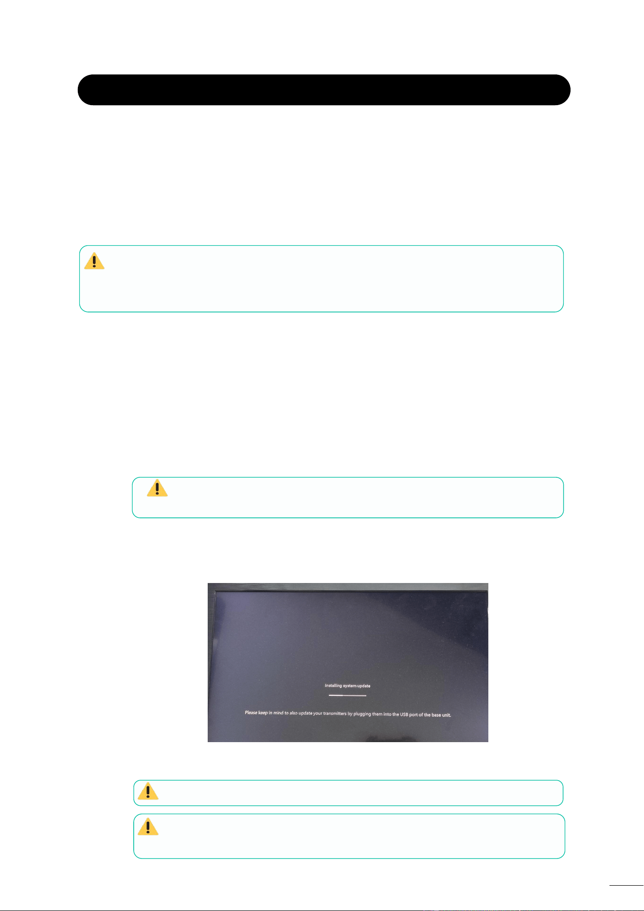
75
All software is stored in P35 base unit and later transferred to the rest of the elements.
After updating the P35 base unit, it is necessary to check whether the other parts need to be
updated as well.
7.1 Upgrading Firmware version of P35
External USB storage drive:
1. Copy the updating file “update.img” to the root directory of the USB drive.
2. Connect the USB drive to either USB 2.0 front port of P35 base unit.
3. P35 recognizes the “update.img”-file at the plugged-in USB stick automatically and
starts the “Full Update” procedure. USB stick can be plugged out within 10 seconds to
stop the update.
Do not disconnect power during upgrading progress. Otherwise, the unit
firmware will be corrupted.
4. The upgrading progress displays as shown, and the P35 will reboot automatically after
completing the updating.
During the update, screen can be temporary dark.
If the progress bar stops at 1%, use another USB stick, since this one may be
defective.
7.
FIRMWARE
UPDATE
There
are
three
different
elements
that
can
require
firmware
updating:
Base
unit:
o
P35
Wireless
transmitters:
o
WMT-H55
o
WMT-C55
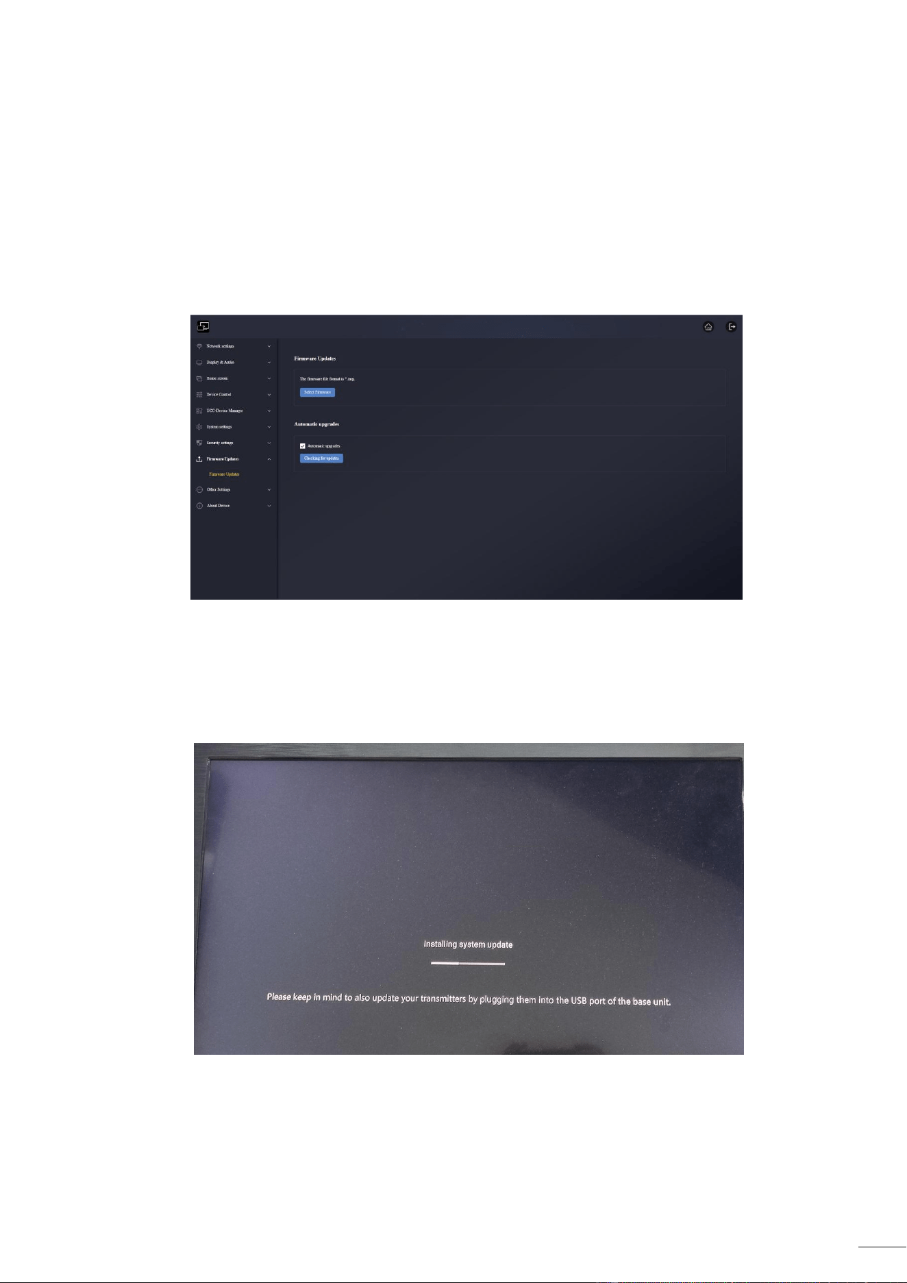
76
5. The display device shows the Home Screen after normal boot of the device, you can
disconnect USB stick.
6. Perform “Factory Reset” when the firmware update is completed.
Web settings:
1. Browse to “Firmware update” section on Web Settings.
2. Select a “update.img” file.
3. The upgrading progress displays as shown below, and the P35 will reboot
automatically after completing the updating.
4. The display device shows the Home Screen after normal boot of the device,
5. Perform “Factory Reset” when the firmware update is completed.
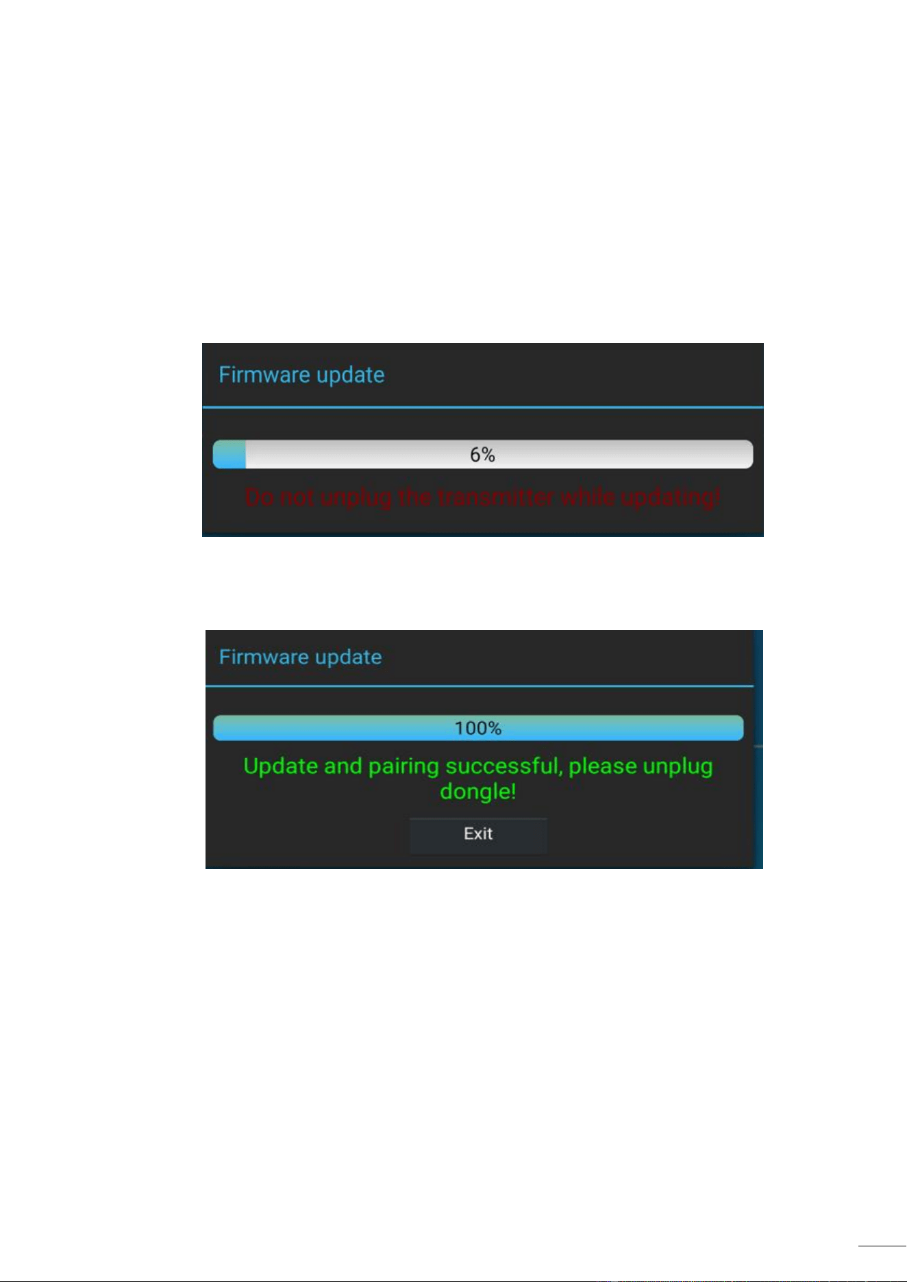
77
3. “Pairing” to the P35 base unit is done automatically afterwards.
7.2
Upgrading
Firmware
version
of
WMT-H55
/
WMT-C55
1.
Plug
the
WMT-H55
/
WMT-C55
to
the
according
USB
front
port
of
P35
to be
updated.It
will
automatically
display
up
a
message
to
indicate
if
the
installed
firmware
of
wireless
transmitter
is
older
and
needs
to
be
upgraded.
2.
The
upgrading
progress
starts
automatically
with
the
progress
bar.
4.
Upgrading
progress
is
finished.
Plug
out
the
wireless
transmitter
(WMT-H55
/WMT-C55)
and
it
is
now
ready
to
use.
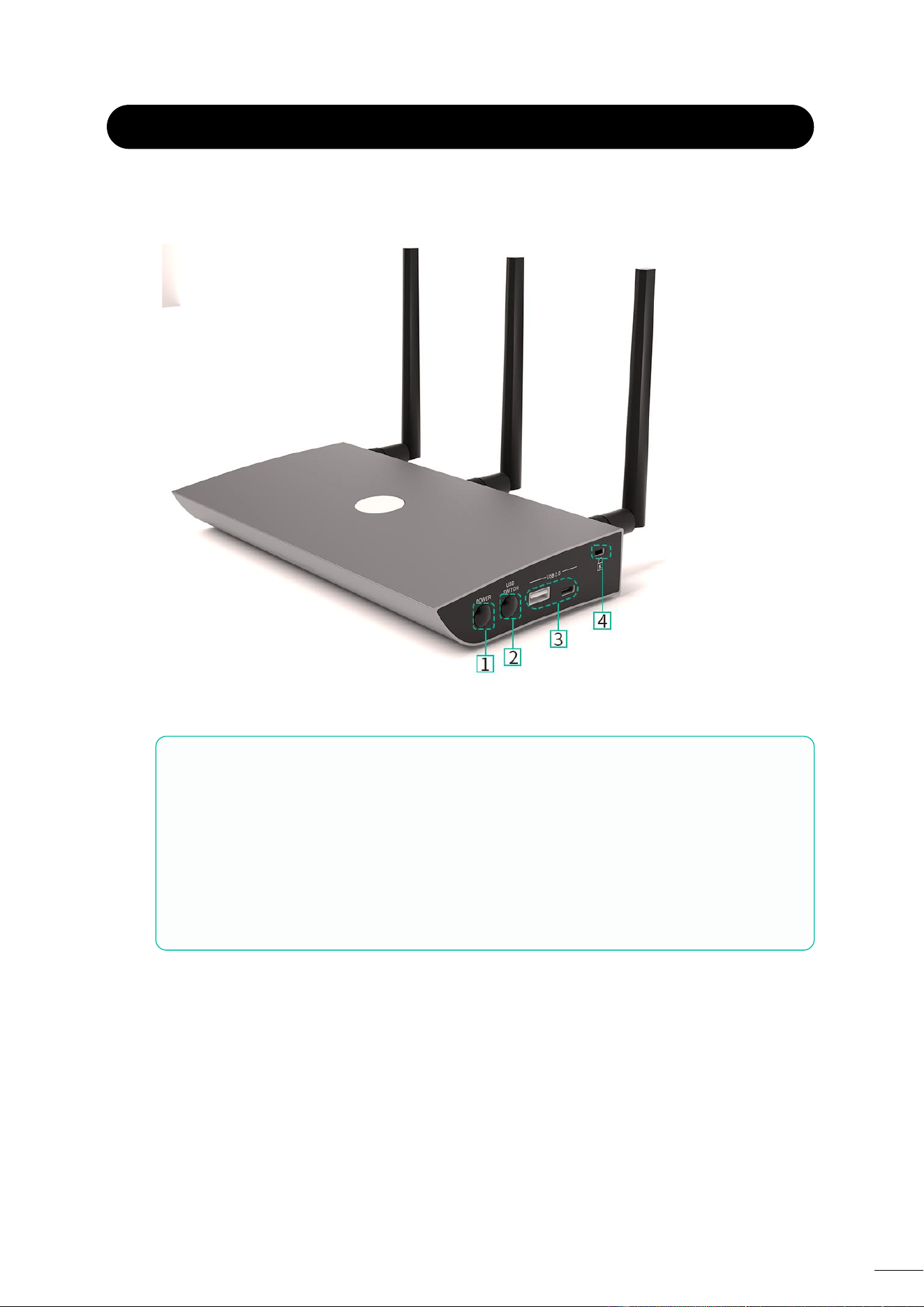
78
8. PANEL FUNCTIONS and WIRELESS TRANSMITTERS
8.1 Front Panel
1.
Power
button:
Turns
the
device
on
or
off
2.
USB
Switch
button:
used
to
switch
between
USB-B
and
Wireless
modes
3.
USB
2.0
port:
USB:
Used
to
pair
WMT-H55
with
P35
and
also
can
be
connected
to
U
disk
and
mouse
Type-C:
For
pairing
WMT-C55
with
P35.
4.
Kingston
lock:
used
to
prevent
theft
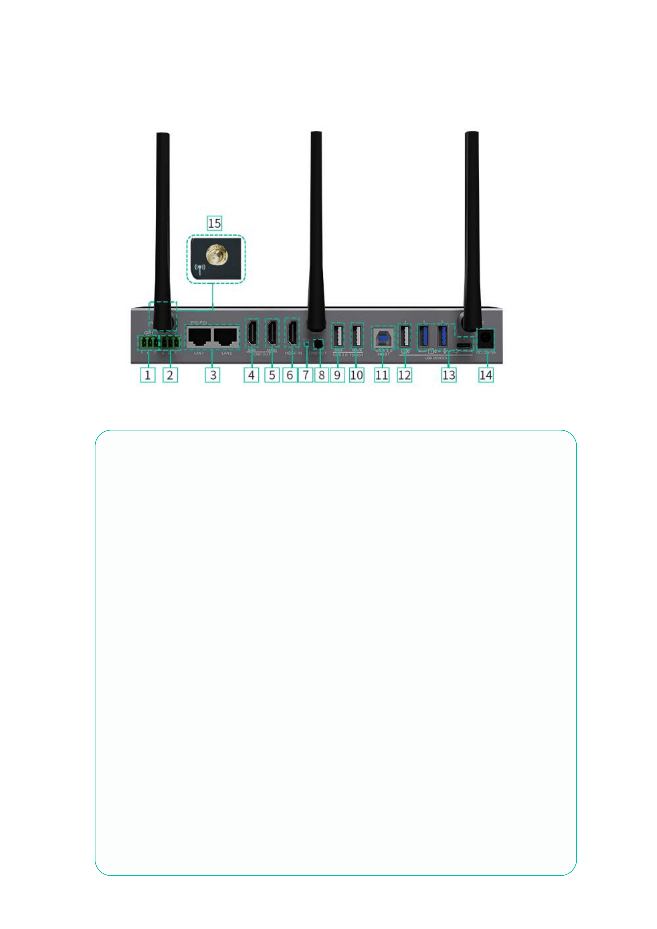
79
8.2 Rear Panel
1. GPI: Two GPI inputs, the maximum
level supports 5V input, and the
function of this input port can be
defined through the Web.
2. RS-232: Simple 232 interface, used to
receive or send serial port commands
to control the machine or other slave
devices.
3. LAN Ethernet port:
>> LAN1: 1000Mbps, supports PoE;
>> LAN2: 1000Mbps;
4. HDMI sub screen output: supporting
up to 1080P.
5. HDMI main screen output: support up
to 4K@60Hz.
6. HDMI IN input: it has been supporting
up to 4K@30Hz.
7. Reset: press button to restore factory
default settings.
8. Line audio output: 3.5mm headphone
unbalanced stereo analog audio output.
9. Sub screen USB 2.0 touch interface:
used to connect the touch screen from
the sub screen.
10. Main screen USB2.0 touch interface:
used to connect the touch screen from
the main screen.
11. USB-B interface: The camera that has
been connected to the base unit can be
switched through this port and used by
other computers such as Room PC.
12. USB 2.0 interface: Connect compatible
cameras and microphone devices for
video conferencing. It should be noted
that if two cameras are connected, one
of them must be connected to this port.
13. USB 3.0 interface: Connect compatible
camera and microphone devices for
video conferencing.
14. DC power socket: local 12V DC power
supply.
15. Antennas: Connect the three antennas
provided to use Miracast and built-in
WiFi functionality.
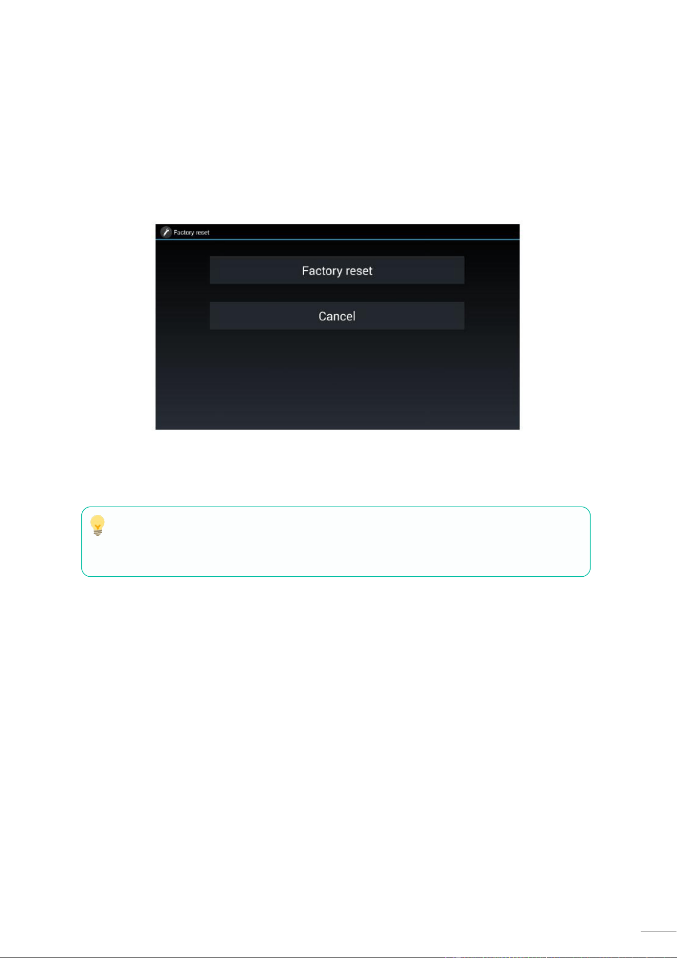
80
8.2.1 Factory Reset Using Rear Panel Button
By using this function, all previous settings will be lost, and you will need to do the set-up once
more.
Start up the P35. When the Home Screen is displayed, press the reset button at the rear panel of
P35. Press this button with a pointed object, e.g., an unbent paper clip for at least 2 seconds, until
the “FactoryReset” page is displayed as below.
The P35 will reboot after 3 seconds to be default configuration.
If P35 HDMI output is not connected to a display and no picture is available, press and hold
the reset button until the red LED indicator on the top surface of P35 lights up to execute the
reset process.
Factory Default Configuration is as following
Wireless Network Configuration:
o Wi-Fi Interface Mode: AP(Access Point)MODE
o SSID discovery and connection: Yes
o Frequency: 5GHZ
o
Channel: 36
Ethernet Network Configuration:
o LAN1 DHCP: Enable
o LAN2 DHCP: Enable
Advnace Setting:
o Internet Access setting: Allow network bridging to LAN 1
o Auto Change Password: 5 minutes
o
Connection Password Mode: 4-digits password begining with 0000

81
Display & Audio
o HDMI Resolution:
Main: Auto
Sub: Auto
o HDMI CEC:
Control Base by Display: OFF
Control Display by Base: OFF
o Audio output: Jack&HDMI
o Audio Volume: 100%
o Maximum number of split-screen views: 4
o Dual-display Output Mode: Mirroring
o Airplay:
Enable Airplay: ON
Airplay Screen Quality: HIGH (1920x1080)
o Miracast:
Enable Miracast: ON
Enable MS-MICE: OFF
o GoogleCast:
Enable Chromecast: ON
Home screen
o
Digital signage: OFF
o Start Screen:
Show the base device name and password when mirroring: OFF
Show PCs user name when mirroring: ON
Hide IP when using a background image other than the default one: OFF
The source video appears on the home screen immediately when connected to
the HDMI IN port: ON
o Shortcuts settings:
Display “Security Level” icon: ON
Display “Downloadl” icon: ON
Display “Information” icon: ON
o Sidebar Control: Large menu (show preview windows)
Device Control
o Telnet Control: ON
o Serial Control: ON
o Function: Receive Command Data
o
GPI Definition:
GPI 1 function settings: USB Channel switching
GPI 2 function settings: USB Channel switching
o
Transmitter button function settings: USB Hub switching

82
UCC-Device Manager:
o USB Hub switching: Auto
System settings
o
Date & time: Use time server(online)
o
Language: English
o Auto Standby: Never
o
Timing Reboot: OFF
Security Settings
o Security Level: Level 1
Other settings
o Auto create launcher: Disabled.
o Clear history after meeting: Always.
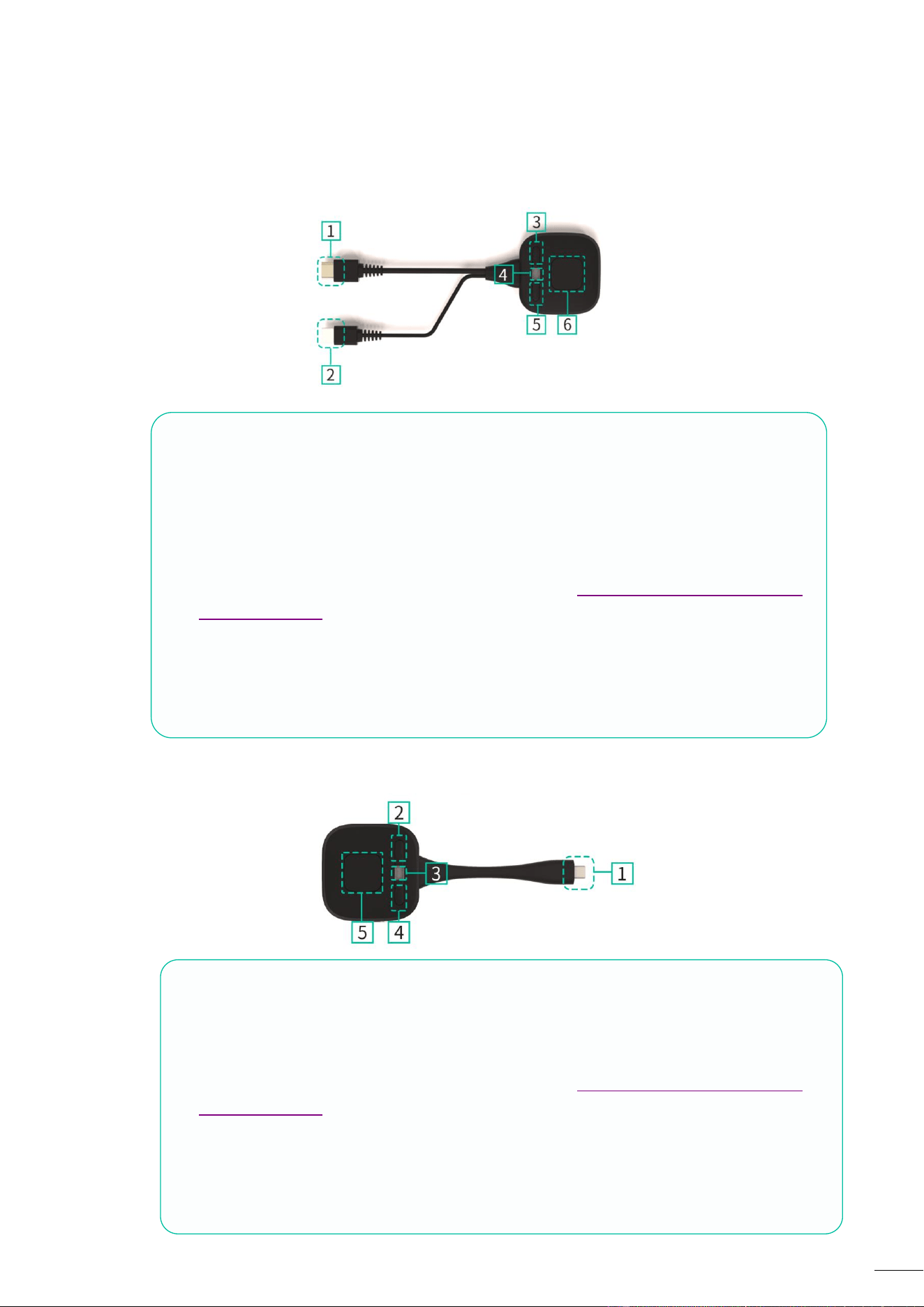
83
1. HDMI connector: Using HDMI connector of the button can be plugged into a
PC/Laptop for sharing your screen.
2. USB connector: Supply power or plug into the P35 for pairing the Button to the P35 or
upgrade the wireless transmitter.
3. Sub button 1: Freeze the mirrored screen. Press this button when mirroring, and the
mirrored screen will be frozen.
4. LED ring indicator: Indicates the status of the button. For further information, see Led
Indicator chapter.
5. Sub button 2: Customize the key function, for example different cameras switch
6. Main Button : Touch the sensor button to start displaying the content of the
PC/Laptop’s screen on the screen. Touch the button during the meeting will toggle the
sharing of the screen.
1. Type C (DP)connector: Using Type C (DP) connector of the button can be plugged into
a PC/Laptop for sharing your screen.
2. Sub button 1: Freeze the mirrored screen. Press this button when mirroring, and the
mirrored screen will be frozen.
3. LED ring indicator: Indicates the status of the button. For further information, see Led
Indicator chapter.
4. Sub button 2: Customize the key function, for example different cameras switch
5. Touching Button: Touch the sensor button to start displaying the content of the
PC/Laptop’s screen on the main screen. Touch the button during the meeting will
toggle the sharing of the screen.
8.3
Wireless
Transmitters
8.3.1
WMT-H55
8.3.2
WMT-C55
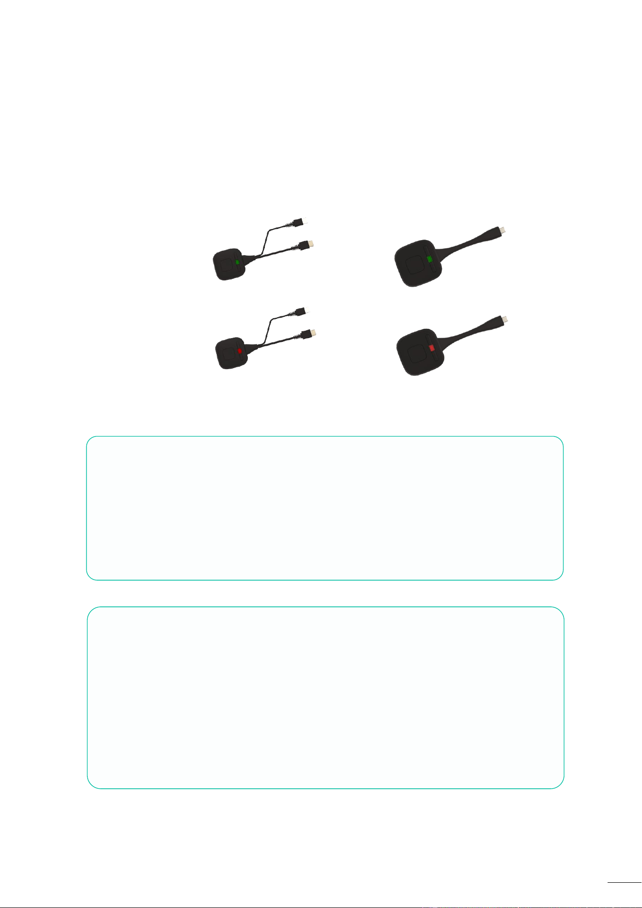
84
WMT-H55
Note:
WMT-C55
is
full
function
type-C
interface
with
DP
Alt
mod
compliance,
which
supports audio
and
video
transmission.
8.3.3
LED
Indicator
WMT-C55
WMT-H55
/
WMT-C55
connected
to
P35:
First
of
all,
a
WMT-H55
/
WMT-C55
needs
to
be
connected
to
the
P35
base
unit:
o
When
LED
indicator
is
blinking
Green:
the
WMT-H55
/
WMT-C55
is
pairing
with
P35
base
unit
or
firmware
upgrading.
o
When
LED
indicator
is
static
red:
pairing
is
done.
WMT-H55
/
WMT-C55
can
be
unplugged
and
ready
to
use.
WMT-H55
/
WMT-C55
connected
to
a
source
device:
First
of
all,
a
WMT-H55
/
WMT-C55
needs
to
be
connected
to
the
source
device.
For
example,to
a
PC:
o
When
LED
indicator
is
blinking
Green:
the
WMT-H55
/
WMT-C55
is
plugged
inthe
laptop
and
initializing.
o
When
LED
indicator
is
static
green:
it
is
ready
to
mirror
the
PC
desktop
on
the
main
screen
connected
to
P35
HDMI
output.
o
When
LED
indicator
is
static
red:
it
is
mirroring
the
PC
desktop
on
the
screen.

85
9. TROUBLESHOOTING
Here you can find some fundamental problems and possible causes, which can be happen during
the use of P35. Find out the problem in the table below and apply the indicated solution.
Problem
Cause
Solution
Using P35 for Android
application in Android
device or Airplay on
iOS device, it can’t find
P35 device.
WiFi password of P35 changed when
android or iOS device is connected
to the WiFi of P35.
Reconnect the mobile by entering
password displayed on Home Screen.
Image quality on the
main display screen is
not good.
The quality or length of the cable
between the P35 and the display or
the connection between these two.
Replace the cable
Use another cable.
Check the cable to be fasten
properly.
Improper resolution for the main
screen.
Change the resolution on the Setting
configuration and match it to the
native resolution of the main screen.
Bad wireless
connection. The
connection between
the transmitter and the
P35 is not stable.
WiFi problems.
Interference in the radio channel.
Overload in the radio channel.
P35 does not automatically jump
to other channels when there are
changes in the RF environment.
Use a WiFi scanner to find a free
wireless frequency and channel and
select it via the setting configuration.
Regularly check the RF environment
if there are frequently changes in
WiFi networks in your environment.
Low signal strength:
Construncion elements, cabinets,
Metal, walls, can cause reflections
deteriorating the wireless signal.
Obstacles between transmitters
and P35 cause lowering of the
wireless strength and quality.
Put the P35 closer to the main
screen.
Change orientation of the antennas
at the rear panel of P35 to the
transmitter direction.
Remove or limit as much as possible
all of the obstructions between the
transmitters and P35.
Avoid placing the P35 base unit in
(metal) cabinets, suspended ceilings,
under tables or in adjoining rooms.
Obvious that can not
get the WirelessMedia
application run when
plug the transmitter to
Laptop.
When you are using P35” for the
first time on your laptop or for
guests, you must copy the Launcher
program WirelessMedia for first on
your Laptop / PC. Run this Starter-
program. You can run the Starter
App without Admin-rights.
download the App via LAN or WiFi of
Base-unit. When the Launcher
program is preinstalled one time,
WirelessMedia is ready to use later
immediately.
Bad connection at USB port
on the Laptop.
Reconnect to the USB port.
Try another USB port.
Reboot the Laptop.
Some types of USB devices might be
blocked as the company policy.
USB port setting on the Laptop
might limit the usage of high power
USB device when on battery power.
If possible, change the USB port policy
on the Laptop.

86
Obvious that low video
performance
(sharpness, audio and
video dropouts, video
stream is jerking, …)
The media-player is not ideal.
The video quality also depends on
the computing power of the PC /
laptop and the interaction and
CPU load with other running
software applications.
A laptop in battery mode can be
switched to reduce the computer
power to save energy. However,
The transmission of HD video
requires a certain amount of CPU
power to guarantee the optimum
quality of the transmission.
Use another media-player (VLC
player…), another browser.
Update the software of your Video-
player to the latest version.
Reduce the CPU usage of other
software applications.
Lower the screen resolution of the
laptop.
Update driver of graphic card.
End low power mode at laptop.
Video is not shown on
screen
The content use HDCP
P35 input cannot support showing
HDCP source. If possible, connect the
source device to local HDMI input at
P35.
The display cable (HDMI) is not
correctly connected.
Insert the display cable to the display
and the Base-unit.
The displays are switched off.
Switch on the display.
The P35 base unit is in standby
mode, “Power-LED” is flashing at
P35 Power-supply is missed.
Power off and on again or insert a
wireless transmitter into laptop.
The message Window
Aero colour scheme
appears when using
Windows 7 “Windows
has detected your
computer’s following
performance is slow…”
P35 uses resource from the GPU. In
combination with other programs
which do so, Windows 7 sometimes
displays this message suggesting
disabling Aero to improve the
performance of Laptop.
It is safe to ignore this message and
choose “Keep the current colour
scheme.”
When the content is
removed from the
screen, however, the
LEDs on the button are
blinking.
Connection to the P35 is lost.
P35 tries to restore the connection
automatically. If it fails, the LEDs on
the button start blinking red.
Unplug the button from your Laptop
and try a new button.
Nothing is shown on
the displays at all
The displays are switched off.
Switch on the display
The display cable is not correctly
connected.
Insert the display cable to the display
and the P35.
The P35 is in standby mode.
Briefly push the standby button on the
P35 or power off and on again.
No LAN connection
with the P35.
Wrong IP address.
IP address is not within LAN range.
DHCP is not enabled.
No WiFi connection
between mobile device
with P35.
Wrong WiFi frequency.
Check mobile device to select the
correct 2.4GHz or 5GHz.
Wrong SSID and password
Enter the correct SSID.

87
Obvious that No audio
when transmit local file
to P35.
Unsupportive audio format as below
listed, including Dolby MS11, DDCO
DTSLBR, DTSE, SRS-THEATERSOUND,
DTS_StudioSound3D, DTS_HD.
If possible, reformat it to the other
audio format, like DD, DD+, HE-AAC,
DTS DMP, WMA, DRA, COOK
There is no sound at
main display.
No connected audio device.
Make sure, the audio is turned on.
Volume is set to OFF.
Adjust the volume level at Options in
menu of P35.
The volume level is set too low in
the options of the WirelessMedia
app program on PC.
Check and adjust the volume in the
WirelessMedia app on PC.
Audio signal may be muted.
Click with the right-mouse button at
speaker icon in taskbar and switch on.
The volume level is set too low.
Adjust the volume level at Options in
menu of P35.
Audio is muted in mixer of volume
in taskbar.
Right-mouse click at speaker icon in
taskbar, open mixer and unmute P35
or “Video Playback”.
The software of used Video-player is
not actual.
Check and update Video-player or try
another player.
An active virus scanner can block
the Audio.
Please check the filter-settings in Virus
scanner.
De-activate the player for a check.
There is no sound with
MacBook.
Maybe the problem of sound-flower
App, which is integrated in driver
WirelessMedia app.
You need Admin-password.
Please check and go to the macOS
System Preferences and select the
“Security & Privacy” tab. Find the
"allow to run/install the sound-
flower" there click on “Allow” next
to “Matt Ingalls”, to allow this
sound-flower to install on the Mac
Book.
Run the WirelessMedia app again,
it’ll auto-install the sound-flower to
the MacBook.

88
There is no sound via
AirPlay.
The volume is set too low, on the
mobile device.
Increase the volume on the mobile
device.
There is no sound on
the mainvscreen, when
mirroring a video by
WirelessMedia APP.
Due to the limit of the Android
system, Android doesn’t provide an
interface to capture the audio. In
this case, there is no sound when
mirroring the video.
Use transmitter or Apple Airplay to do
mirroring when necessary.
Can not update the
firmware of the P35.
Flash disk format is NTFS.
Please re-format the flash disk to be
FAT format to update it.
Can not work airplay
with MacBook / iPhone
/ iPad.
Operation System Requirement Mac
OS 10.9, iOS 8.0 and later
(WirelessMedia app).
To use AirPlay, you must connect
the iOS device to the WiFi of P35
and enable the AirPlay feature in the
Control Center.
Update the iOS device to a newer
operating system.
Poor video-quality with
AirPlay.
There are 2 states for AirPlay:
a.) Mirroring: 1: 1 copy of the screen
b.) Streaming: Videos from (Internet
or Youtube); the image will not
be displayed on the iOS device.
=> picture is jerky.
Please check and reduce “Quality” in
settings of Youtube, for example from
“Automatic” to 720p.
Can not work with
Android device.
Operation System Requirement is
that Android 2.3 version and later
(WirelessMedia app).
Update to the later OS.

89
10. TECHNICAL DATA
10.1 Technical Specifications
P35
Video Output
2×HDMI type A 19-pin female connector
Video Output Resolution
HDMI Main:
3840x2160@60Hz, 3840x2160@30Hz
1920x1080@60Hz, 1280x720@60Hz
HDMI Sub:
1920x1080@60Hz, 1280x720@60Hz
Video Output Capabilities
HDMI Main: HDMI1.4/HDMI2.0
HDMI Sub: HDMI1.4
Video Output HDCP
HDMI Main: HDCP1.4/HDCP2.2
HDMI Sub: HDCP1.4
Video Input
1×HDMI type A 19-pin female connector
Video Input Resolution
3840x2160@30Hz, 1920x1080@60Hz, 1280x720@60Hz
Video Input Capability
HDMI1.4
Video Input HDCP
HDCP1.4
Analog Audio Output
1×3.5mm computer audio interface
LAN Interface
RJ45 x2; 1000Mbps x2
USB Interface
USB3.0: typeA x2, typeC x1;
USB2.0: typeA x4, typeC x1;
Audio Input
AirPlay, Miracast, Chromecast, Windows/MAC App, WMH, WMC
Control Interface
Phoenix terminal 3.5mm RS232 interface
GPI Interface
Phoenix terminal 3.5mm 2xGPI
Maximum Display Window
≥4+14 (4 main screens + 14 preview control windows)
Maximum Connected Transmitter
≥16
Wireless Data Rate
Up to 1200Mbps
Video Play Frame Rate
20-60 FPS
Transmission Delay
80ms/min
Wireless Transmission Protocol
WIFI IEEE 802.11 a/g/n/ac/ax
Frequency Band
2.4 GHz & 5 GHz
WIFI Antenna
MIMO 2x2, MIMO 1x1

90
Video Input Connectors
1×HDMI type A 19P male interface
Video Input Resolution
3840x2160@30Hz, 2540x1440@60Hz
1920x1080@60Hz, 1280x720@60Hz
Video Capability
HDMI1.4
HDCP
HDCP1.4
USB Interface
USB 2.0 x1
Audio Input
HDMI PCM 2CH
Control Interface
USB HID touch passback
Video Play Frame Rate
20-60 FPS
Transmission Delay
Wireless Transmission Protocol
Frequency Band
WIFI Antenna
Wireless Data Rate
Dimensions (W x D x H)
Weight
Storage Temperature
Humidity
Power Supply
Power Consumption
<100ms
WIFI IEEE 802.11 a/g/n/ac
2.4 GHz & 5 GHz
Ceramic Antenna
Up to 1200Mbps
80cm x 65cm x 1.3cm
HDMI cable length: 11cm
USB cable length: 21cm
0.2lbs(100g)
-4° ~ +140° F (-20° ~ +60° C)
20%-90% (non-condensing)
USB
2.5W(MAX)
Dimensions (W x D x H)
220mm x 130mm x 34mm
280mm x 130mm x 34mm (including antenna)
Weight
2.05lbs(930g)
Storage Temperature
-4° ~ +140° F (-20° ~ +60° C)
Humidity
20%-90% (non-condensing)
Power Supply
DC 12V or POE
POE Standard
IEEE802.3at
Power Consumption
30W(MAX)
Video Input Connectors
1×USB-C 24P male interface
Video Input Resolution
3840x2160@30Hz, 2540x1440@60Hz
1920x1080@60Hz, 1280x720@60Hz
Video Capability
DP1.2
USB Interface
USB 2.0 x1
Audio Input
HDMI PCM 2CH
Control Interface
USB HID touch passback
WMT-H55 (optional accessory)
WMT-C55 (optional accessory)
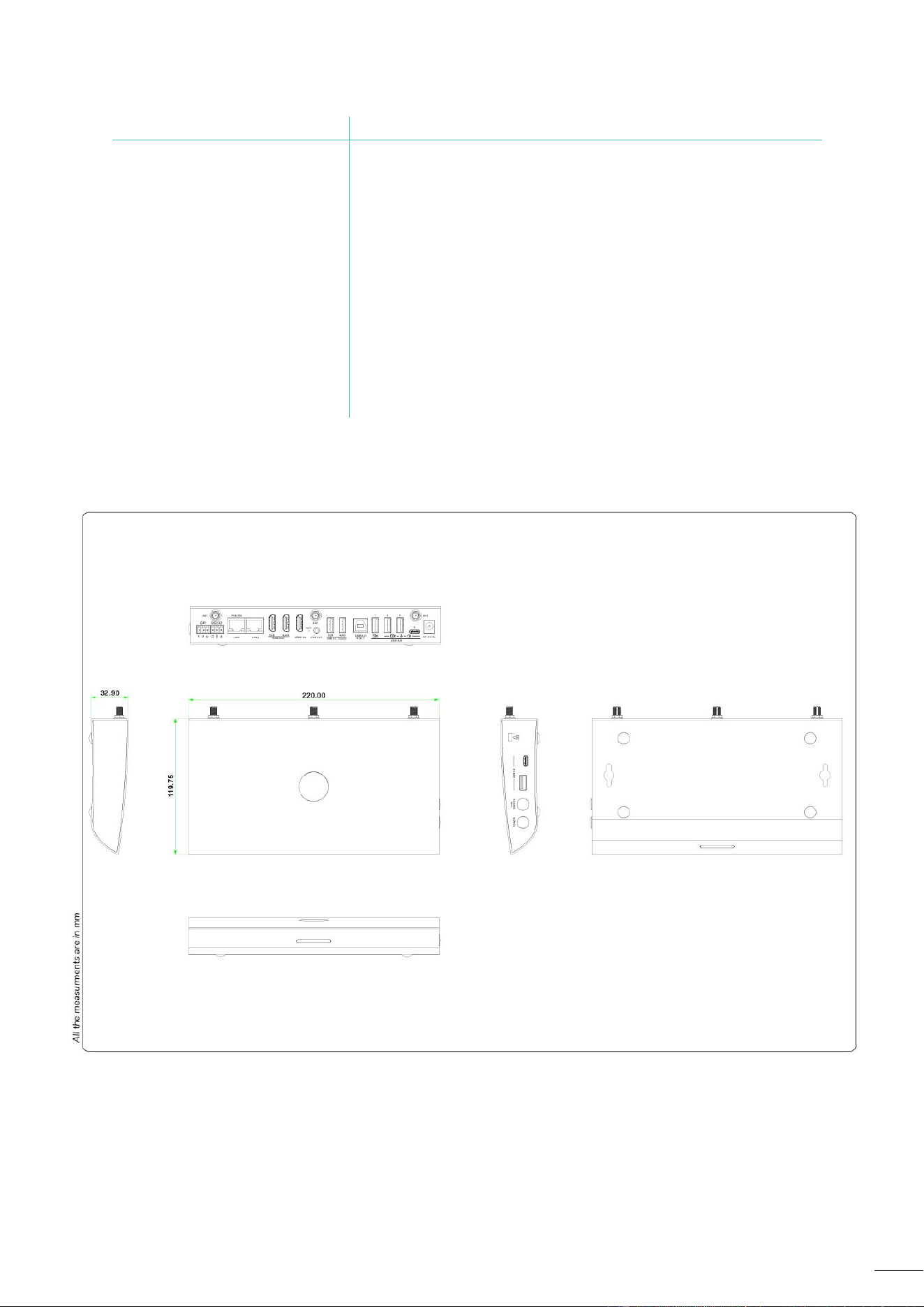
91
10.2 Mechanical Diagram
P35
Video Play Frame Rate
20-60 FPS
Transmission Delay
Wireless Transmission Protocol
Frequency Band
WIFI Antenna
Wireless Data Rate
Dimensions (W x D x H)
Weight
Storage Temperature
Humidity
Power Supply
Power Consumption
<100ms
WIFI IEEE 802.11 a/g/n/ac
2.4 GHz & 5 GHz
Ceramic Antenna
Up to 1200Mbps
80cm x 65cm x 1.3cm
USB C cable length: 11cm
0.2lbs(100g)
-4° ~ +140° F (-20° ~ +60° C)
20%-90% (non-condensing)
USB
3.0W(MAX)
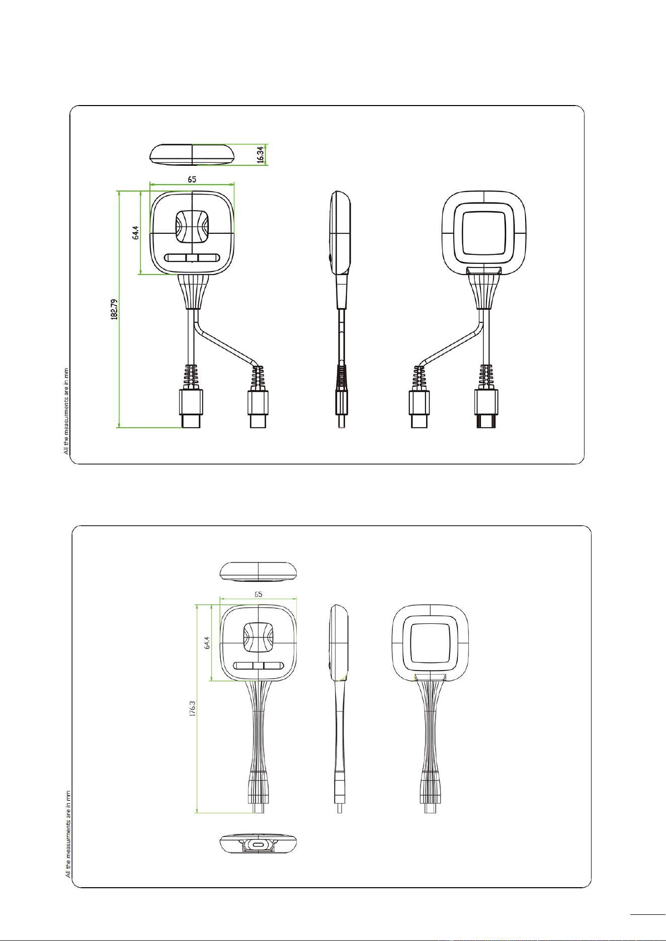
92
WMT-H55
WMT-C55

FCC Warming:
This device complies with part 15 of the FCC Rules. Operation is subject to the following two
conditions:
(1)This device may not cause harmful interference, and
(2)this device must accept any interference received, including interference that may cause undesired
operation.
Any Changes or modifications not expressly approved by the party responsible for compliance could
void the user's authority to operate the equipment.
Note: This equipment has been tested and found to comply with
the limits for a Class B digital device, pursuant to part 15 of the FCC
Rules. These limits are designed to provide reasonable protection against harmful interference in a
residential installation. This equipment generates uses and can radiate radio frequency energy and, if
not installed and used in accordance with the instructions, may cause harmful interference to radio
communications. However, there is no guarantee that interference will not occur in a particular
installation. lf this equipment does cause harmful interference to radio or television reception, which
can be determined by turning the equipment off and on, the user is encouraged to try to correct the
interference by one or more of the following measures:
-Reorient or relocate the receiving antenna.
-
Increase the separation between the equipment and receiver.
-
Connect the equipment into an outlet on a circuit different from that to which the receiver is
connected.
-
Consult the dealer or an experienced radio/TV technician for help.
*RF warning for Portable device:
The device has been evaluated to meet general RF exposure requirement.
The device can be used in portable exposure condition without restriction.
SAR Statement(2AWJK-WMT-C55):
SAR tests are conducted using standard operating positions according standards with the device
transmitting at its highest certified power level in all tested frequency bands, although the SAR
is
determined at the highest certified power level, the actual SAR level of the device while operating can
be well below the maximum value. This model product has been tested and meets the RF exposure
guidelines with the test distance 0mm for body worn. The highest SAR
1g
value is 0.450 W/Kg for body
worn. The use of belt clips, holsters and similar accessories should not contain metallic components
in its a
ssembly. The use of accessories that do not satisfy these requirements
may not comply with RF exposure requirements, and should be avoided
SAR Statement(2AWJK-WMT-H55):
SAR tests are conducted using standard operating positions according standards wit
h the device
transmitting at its highest certified power level in all tested frequency bands, although the SAR is
determined at the highest certified power level, the actual SAR level of the device while operating can
be well below the maximum value. This model product has been tested and meets the RF exposure
guidelines with the test distance 0mm for body worn. The highest SAR
1g
value is 0.443 W/Kg for
body worn. The use of belt clips, holsters and similar accessories should not contain metallic
components in its assembly. The use of accessories that do not satisfy these requirements
may not comply with RF
exposure requirements, and should be avoided
93