
315-750-4008
This manual contains important safety precautions. Read and understand this manual carefully
before using the product. Failure to follow these instructions may result in serious injury.
The specifications, descriptions, and illustrations in this manual are as accurate as possible at
the time of publication, but are subject to change without notice.
Keep this manual with the product for future reference.
www.mechmaxx.com
OPERATOR’S MANUAL
EN
RELIABLE EFFICIENT VALUE
3-POINT
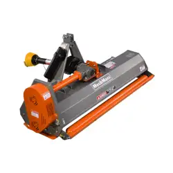
DRUM MOWER
150235SKU
Model
DM53


Before operating the machine, please read this
manual carefully and make sure you understand all
safety warnings, assembly instructions, operating
procedures, maintenance requirements, and
troubleshooting information. Proper assembly, safe
operation, and regular maintenance will help ensure
reliable performance, extend the service life of the
machine, and reduce the risk of personal injury or
equipment damage.
The illustrations and specifications in this manual
are for reference only. The actual product may vary
slightly due to model configuration, production
updates, or technical improvements. If you have any
questions during assembly, operation, or mainte-
nance, stop using the machine and contact your
dealer or service representative for assistance.
This machine is designed for specific applications
only. We strongly recommend that this machine not
be modified or used for any application other than
its intended purpose. If you have any questions
regarding a particular application, DO NOT use the
machine until you have contacted us to determine
whether the application can or should be performed
with this product.
Use only genuine MechMaxx parts when servicing or
repairing this machine. Replacement parts
manufactured by other companies may fit this
machine, but they may present potential safety
hazards. Replacement parts can be purchased from
your authorized MechMaxx dealer.
• The serial number of your machine
• The part number
• The part description
• The quantity needed
1
INTRODUCTION
INTRODUCTION
Indicates an imminently hazardous situation
which, if not avoided, will result in death or
serious injury.
SCAN THE QR CODE TO
CONTACT US
Indicates a potentially hazardous situation which,
if not avoided, could result in death or serious
injury.
Indicates a potentially hazardous situation which,
if not avoided, may result in minor or moderate
injury. It may also be used to alert against unsafe
practices.
Ordering Parts
Safety Definitions
3-POINT DRUM MOWER
www.mechmaxx.com
Tractor Power Required:
NO. Of Blades:
Model:
Cutting width:
PTO Speed:
NO. Of Drums:
Serial No.:
DRUM
MOWER

TABLE OF CONTENTS
TABLE OF CONTENTS
TABLE OF CONTENTS
SPECIFICATIONS
IMPORTANT SAFETY INFORMATION
SAFETY SIGNS
Transport Machinery Safely
2
3
4
Safety Always
6
PTO Shaft Maintenance
Lubrication Parts
19
General Service
19
20
Tightening Torque
21
Replacing the Blade
22
Storage
23
TROUBLESHOOTING
24
PARTS DIAGRAM
26
Practice Safe Maintenance
Wear Protective Equipment
CONTENTS SUPPLIED
6
6
7
ASSEMBLY INSTRUCTIONS
8
Preparation Before Assembly
8
Protective Cover Assembly
8
Swing Arm Assembly
9
Vertical Arm Assembly
10
Installing the Hitch Assembly
10
PTO Driveline Installation
Shortening the PTO driveline
Adjusting the PTO driveline
6
6
11
12
14
13
14
16
OPERATION
17
Checklist Before Operation
17
Leveling Adjustment
18
Parking Leg Assembly
KNOW YOUR MACHINE
CONNECTION TO THE TRACTOR
19
SERVICE AND MAINTENANCE
19
Gearbox Maintenance
23
STORAGE AND TRANSPORT
23
Transport
2
3-POINT DRUM MOWER

SPECIFICATIONS
3
SPECIFICATIONS
3-POINT DRUM MOWER
Model DM53
Tractor Power Required
Working Width
Avg. Cutting Height
Number Of Drums
Number Of Blades
Working Capacity
PTO Shaft RPM
Driveline Shaft Length
Spline End
3-Point Hitch
Gear Fluid Capacity Of Gear Box
Gearbox Oil Type
Dimensions (L x W x H)
Finish
Warranty
Shipping Box
Weight (N.W./G.W.)
25-40 HP
53 in
2 in
2
8
3.34 acre/h
540 RPM
T2S-720-RA1; 28.3-34.2 in
1.375 in, Z6
CAT 1
0.72 gal
SAE 85W-90 API GL-5
98 x 27 x 39 in
Powder Coat Paint / Galvanized Steel
1 Year
57 x 38 x 23 in
408 / 474 lbs
4
SAFETY SIGNS
SAFETY SIGNS
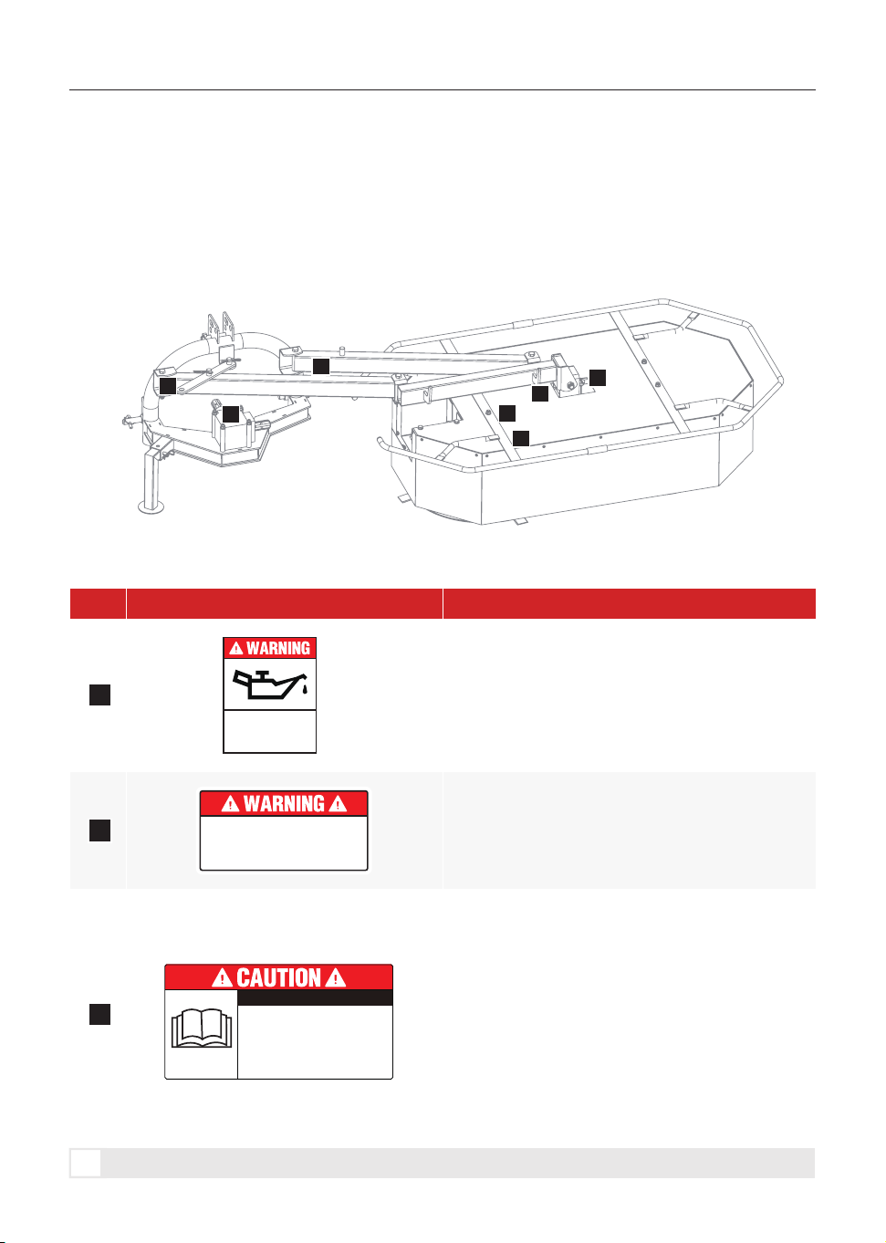
The SAFETY SYMBOL alerts you to a potential personal injury hazard. When you see this symbol, be alert and
carefully read the message that follows it. In addition to equipment design and configuration, hazard control and
accident prevention depend on the awareness, care, judgment, and proper training of personnel involved in the
operation, transport, maintenance, and storage of the equipment.
LABEL MEANING
1
2
3
3-POINT DRUM MOWER
3
1
1
4
6
2
5
WARNING! Oil must be added before first use.
WARNING! The PTO driveline MUST be measured
and cut, if required, according to the Owner’s
Manual. Failure to do so may damage both the
tractor and the implement.
CAUTION! Read and understand the operator’s
manual before use. Wear proper clothing and do
not operate the machine when intoxicated,
fatigued, ill, or pregnant. Keep children away from
the machine. Check the surrounding area and
inspect the machine before operation. Before
inspection, adjustment, or cleaning, disengage all
drives, including the PTO, and stop the engine.
Reinstall all guards and covers before use. When
lending the machine to others, ensure they read
the manual carefully before operating.
MUST ADD OIL
BEFORE FIRST
USE
The PTO driveline MUST be measured
and cut, if required, according to the
Owner’s Manual. Failure to do so will
result in damage to both the tractor and
the implement.
1. Do not wear loose clothing while operating.
2. Do not operate under the influence of alcohol or drugs, or when
fatigued, ill, or otherwise unfit to operate safely. Keep children away
from the machine.
3. Make sure the area is clear before operation.
4. Inspect the machine before operation.
5. Disengage all drives, including the PTO, stop the tractor engine, set
the parking brake, and remove the key before inspection, adjustment, or
cleaning.
6. Reinstall all guards and covers before operation.
7. If the machine is loaned to another person, make sure they read the
operator's manual before use.
Read the operator's manual before
using the machine.

5
SAFETY SIGNS
These safety signs and symbols are designed to help you operate the Drum Mower safely.
1. Keep all safety labels clean and legible.
2. Replace any damaged or missing safety labels.
3. When replacing a component that carries a safety label, install the correct replacement label specified by
MechMaxx. When ordering replacement components, make sure the required safety labels are included.
3-POINT DRUM MOWER
DANGER! Read the manual before operation. Keep
hands, feet, and bystanders away from moving
parts. Wear proper personal protective equipment.
LABEL MEANING
4
5
To avoid Injury or Machine Damage:
Operate only with 540 rpm PTO
CAUTION! To avoid injury or machine damage,
operate only with a 540 rpm PTO.

6
Always remain alert and follow safe operating
practices, even if certain precautions are not
specifically covered in this manual. Operate the
machine only as instructed.
3-POINT DRUM MOWER
Safety Always
Practice Safe Maintenance
Transport Machinery Safely
IMPORTANT SAFETY INFORMATION
IMPORTANT SAFETY INFORMATION
Thoroughly read and understand the instructions
given in this manual before operation. Refer to the
“Safety Decal”, read all instructions noted on them.
Do not allow anyone to operate this equipment who
has not fully read and comprehended this manual
and who has not been properly trained in the safe
operation of the equipment.
1. Operator should be familiar with all functions of
the unit. Operate implement from the driver’s seat
only.
2. Make sure all guards and shields are in place and
secured before operating the implement.
3. Do not leave tractor or implement unattended
with engine running.
4. Dismounting from a moving tractor could cause
serious injury or death.
5. Do not stand between the tractor and implement
while the tractor is moving or the engine is running.
Before entering the hitch area, set the parking brake,
stop the engine, and remove the key.
6. Keep hands, feet, and clothing away from
power-driven parts.
7. Wear snug fitting clothing to avoid entanglement
with moving parts.
8. Watch out for wires, trees, etc., when raising
implement. Make sure all persons are clear of
working area.
9. Avoid excessively sharp turns, especially with the
PTO engaged. Excessive driveline angles or contact
between the mower and tractor may cause
equipment damage or serious injury.
1. Comply with state and local laws.
2. Maximum transport speed for implement is 18
mph. Do not exceed. Never travel at a speed which
does not allow adequate control of steering and
stopping. Some rough terrain requires a slower
speed.
3. Disengage the PTO and allow all rotating parts to
stop before raising the mower to the transport
position.
4. Raise and secure the mower in the transport
position. Maintain adequate ground clearance and
reduce speed on rough, uneven, or hilly terrain.
Wear Protective Equipment
1. Understand the procedure before performing any
work. Use the proper tools and equipment. Refer to
the Operator's Manual for additional information.
2. Work in a clean dry area.
3. Lower the implement to the ground, put tractor in
park, turn off engine, and remove key before
performing maintenance.
4. Allow implement to cool completely.
5. Inspect all parts. Make sure parts are in good
condition and installed properly.
6. Remove buildup of grease, oil or debris.
7. Remove all tools and unused parts from
implement before operation.
8. Prepare for emergencies
9. Be prepared if a fire starts.
10. Keep a first aid kit and fire extinguisher handy.
11. Keep emergency numbers for doctor, ambulance,
hospital and fire department near phone.
1. Protective clothing and equipment should be
worn.
2. Wear clothing and equipment appropriate for the
job. Avoid loose fitting clothing.
3. Prolonged exposure to loud noise can cause
hearing impairment or hearing loss. Wear suitable
hearing protection such as earmuffs or earplugs.
4. Operating equipment safely requires the full
attention of the operator. Avoid wearing radio
headphones while operating machinery.
CONTENTS SUPPLIED
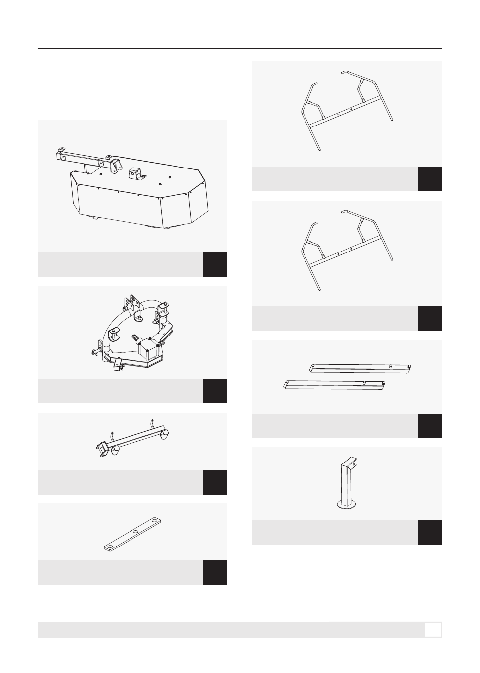
Before assembling the Drum Mower, verify that all
parts and hardware are included and that the
quantities are correct.
X1
X1
X2
X1
X1
X1
7
3-POINT DRUM MOWER
X1
*If any parts are missing or damaged, please contact us.
Main Frame
Hitch Assembly
Vertical Arm
Swing Arm
Adjusting Plate
Parking Leg
Right Guard Cover
X1
Left Guard Cover
CONTENTS SUPPLIED
8
3-POINT DRUM MOWER
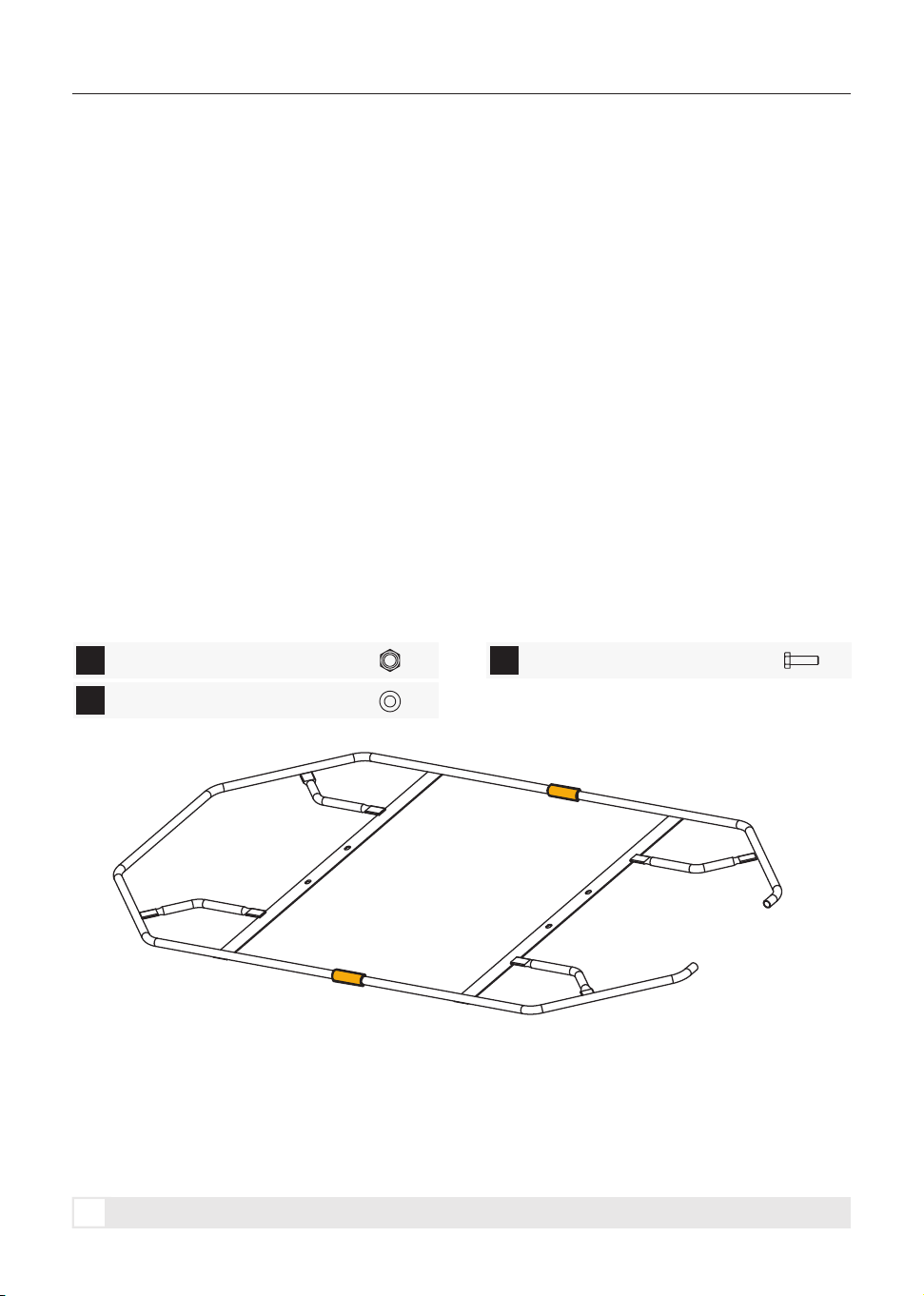
Protective Cover Assembly
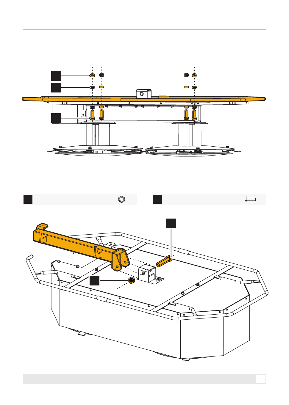
1. Align the tubes of the left and right guard covers.
2. Insert the Right Guard Cover into the Left Guard Cover, as shown in the figure. (See Figure 1)
Figure 1
ASSEMBLY INSTRUCTIONS
ASSEMBLY INSTRUCTIONS
Assembly procedures vary by model. If assembly is required, use appropriate lifting equipment and follow safe
handling practices. Loosely assemble components first, align parts, and then tighten hardware to final torque.
The exploded views and complete parts lists are provided in the Parts Diagrams and Parts Lists section at the end of
this manual. The figures in this section are for assembly reference only.
Note:
All required bolts and fasteners are pre-installed on the machine at the factory. Remove them as needed
during assembly and reinstall them according to the following instructions.
• Park the tractor and implement on a firm, level surface. Set the parking brake, shut off the engine, and remove
the key.
• Check all parts and hardware against the parts lists before assembly.
• Do not place hands, feet, or any part of the body under unsupported components.
• Loosely assemble components first, then tighten hardware after all parts are aligned. All pins, lock pins,
retaining clips, and lynch pins must be fully inserted and secured.
• Some bolts, nuts, pins, or washers may be shipped pre-installed in the corresponding holes. Remove and
reinstall them as required during assembly.
Preparation Before Assembly
Hex lock nut M10
X4A
C
B
Hex bolt M10 X 50mm
Flat washer 10
X8
X4
9
3-POINT DRUM MOWER
Swing Arm Assembly
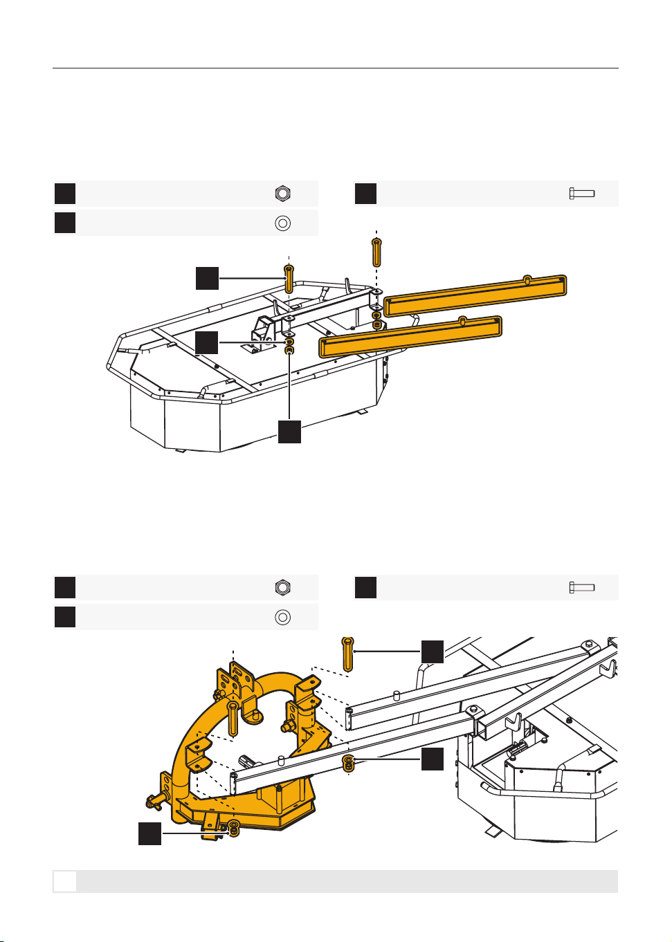
1. Align the two holes on the Swing Arm with the outside of the lugs on the Main Frame.
2. Secure it using Hex Bolt M16 × 120 mm and Hex Lock Nut M16. (See Figure 3)
3. Align the four holes on the guard cover with the holes on the Main Frame.
4. Secure the cover to the hood using Hex Lock Nuts M10, Flat Washers 10, and Hex Bolts M10 × 50 mm. The
heads of the four bolts should be positioned under the hood, while the lock nuts should be positioned on top of
the guard cover. (See Figure 2)
Figure 2
Figure 3
ASSEMBLY INSTRUCTIONS
Hex lock nut M16
X1A
B
Hex bolt M16 X 120mm
X1
A
A
B
B
C
10
3-POINT DRUM MOWER
Vertical Arm Assembly
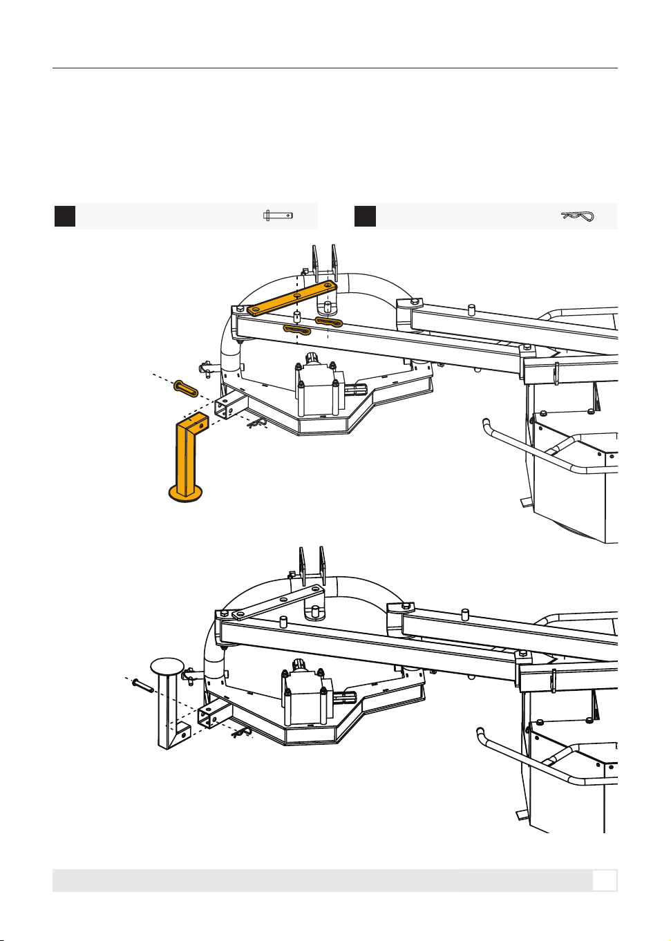
1. Align the two holes on the Vertical Arm with the lugs on the Swing Arm.
2. Secure the Vertical Arm to the inside of the lugs using Flat Washers 14, Hex Lock Nuts M14, and Hex Bolts
M14 × 120 mm. (See Figure 4)
The bolts should pass through the Vertical Arm and the lug seat from top to bottom.
1. Adjust the positions of the two Vertical Arms so that they fit into the openings of the Hitch Assembly
connecting plates.
2. Align the four holes on the Hitch Assembly with the holes on the Vertical Arms.
3. Secure the Vertical Arms to the inside of the lugs using Flat Washers 14, Hex Lock Nuts M14, and Hex Bolts
M14 × 120 mm. (See Figure 5)
Figure 4
Figure 5
Installing the Hitch Assembly
ASSEMBLY INSTRUCTIONS
Hex lock nut M14
X2A
C
B
Hex bolt M14 X 120mm
Flat washer 14
X2
X2
Hex lock nut M14
X2A
C
B
Hex bolt M14 X 120mm
Flat washer 14
X2
X2
C
A
B
C
B
A
11
3-POINT DRUM MOWER
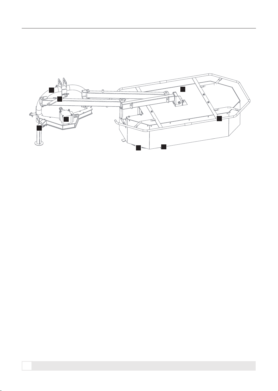
1. Align the tube of the Parking Leg with the mounting position on the Hitch Assembly.
2. Insert the Pin Shaft 12×70 through the holes and secure it with the Type B Pin M3.5×75.
3. Insert the Adjusting Plate into the slot of the Vertical Arm and secure it with the Type B Pin M3.5 x 75. (See
Figure 6)
Two positions are available for adjustment.
Transport and Storage Position:
Figure 6
Parking Leg Assembly
ASSEMBLY INSTRUCTIONS
X1A
C
X3
Pin Shaft 12X70
Type B Pin M3.5X75
12
3-POINT DRUM MOWER
KNOW YOUR MACHINE
KNOW YOUR MACHINE
Before operating the Drum Mower, read this operator's manual carefully. Become familiar with the location and
function of all controls and features. Keep this manual for future reference.
1. Drawbar: Connects the mower to the tractor and
supports the mower during operation and
transport.
2. Shaft Locking Bracket: Secures the PTO shaft
when it is disconnected or not in use.
3. Hood: Covers the cutting area and helps contain
grass, debris, and other material thrown by the
rotating blades.
4. Parking Leg: Supports the mower in a stable
position when it is disconnected from the
tractor.
5. Speed-Increaser Gearbox: Increases the input
speed and transfers power from the PTO driveline to
the cutting system.
6. Blade Disc: Rotates at high speed and carries the
cutting blades for mowing grass and vegetation.
7. Blade: Cuts grass and vegetation as the blade
disc rotates.
8. Guard Cover: Shields moving components and
helps prevent accidental contact with the cutting
system.
1
2
3
7
8
4
5
6
13
3-POINT DRUM MOWER
CONNECTION TO THE TRACTOR
CONNECTION TO THE TRACTOR
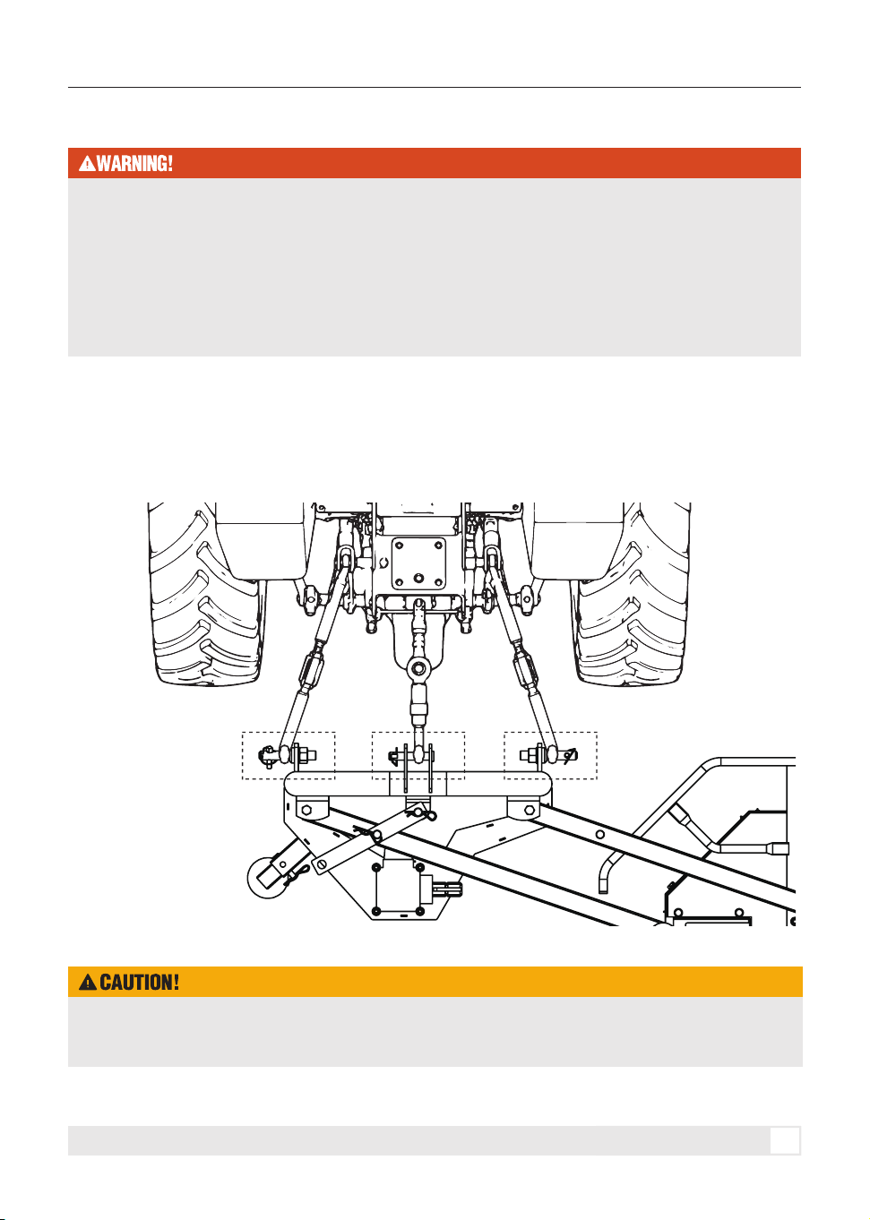
1. Align the lower hitch arms with the implement hitch pins and secure them with locking pins.
2. Attach the upper link in the same way.
3. Start the tractor and slowly raise the rear hitch to lift the mower.
4. Move the spreader pins on both sides to the top position and secure them in the last holes.
5. To disconnect the implement, follow the steps above in reverse order.
• Only the operator is allowed within 50 m (164 ft)of the machine.
• The operator must remain near the machine until all connection operations are complete.
• Never step over or cross a PTO shaft. Never enter the area between the tractor and mower while the tractor
is moving or the engine is running. Before entering the hitch area, set the parking brake, stop the engine,
and remove the key.
• For safety, always connect the machine on level ground.
• After completing the connection, keep the machine on level ground.
After connecting the mower to the tractor, make sure the locking/retaining pins are installed and secured on
all three hitch pins.
14
3-POINT DRUM MOWER
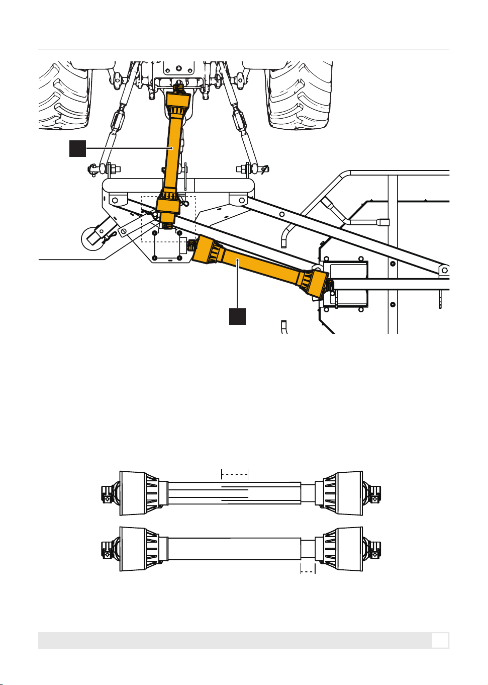
• After shutting off the tractor engine, install the PTO driveline onto the splined shaft of the implement and
connect it to the tractor PTO driveline. Refer to the label attached to the PTO driveline for the connection point
and direction of rotation.
• The PTO driveline without clutch between the two gearboxes (A) must be installed first, followed by the PTO
driveline with clutch connecting the machine to the tractor (B).
• After installation, check to make sure the PTO driveline operates properly and is not obstructed.
PTO Driveline Installation
Listed below are common practices that may or may not be applicable to the products described in this manual.
CONNECTION TO THE TRACTOR
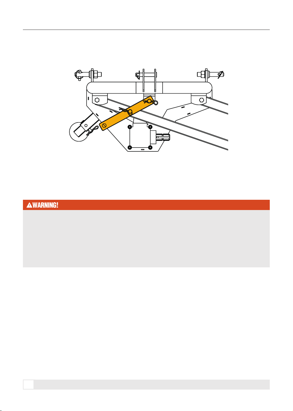
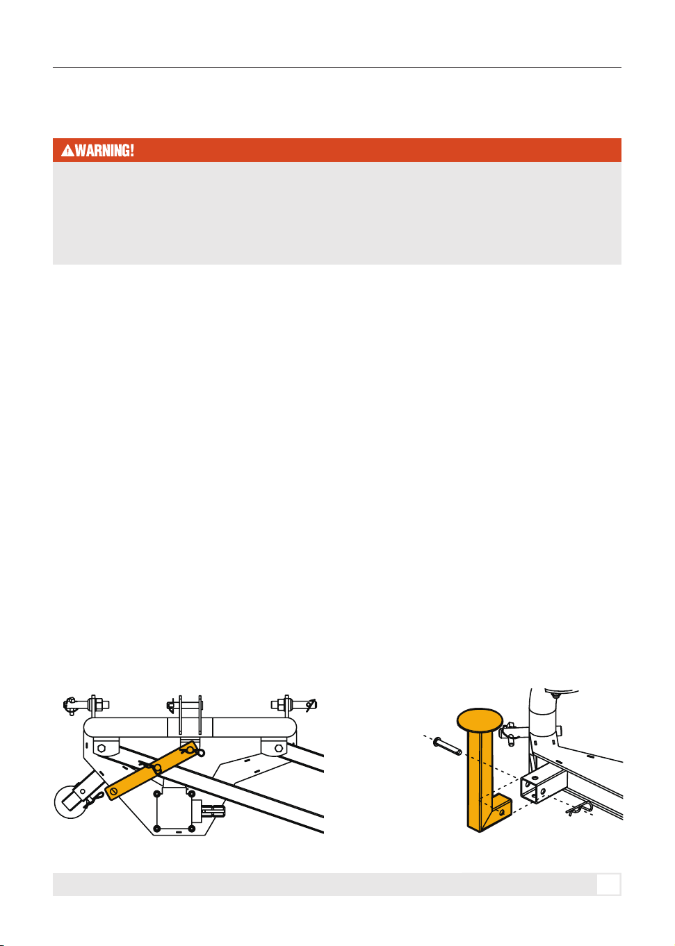
6. When the mower is set to the lateral operating position, install the Adjusting Plate as shown in Figure 7 and
secure it with the Type B Pin M3.5 x 75.
7. Raise and secure the Parking Leg before operation.
Do not engage the tractor PTO while connecting or disconnecting the PTO driveline. Never stand near a
rotating PTO driveline. Body parts or clothing can become entangled, causing serious injury or death.
Do not use a power take-off adapter. The adapter will increase strain on the tractor's power take-off shaft
causing possible damage to shaft and PTO driveline. It will also defeat the purpose of the tractor's power
take-off shield.
Make certain PTO driveline yokes are securely fastened at each end. A loose yoke can work free allowing the
PTO driveline to rotate uncontrollably.
Figure 7
15
3-POINT DRUM MOWER
The clutch end of the
PTO driveline must be
connected to the
gearbox.
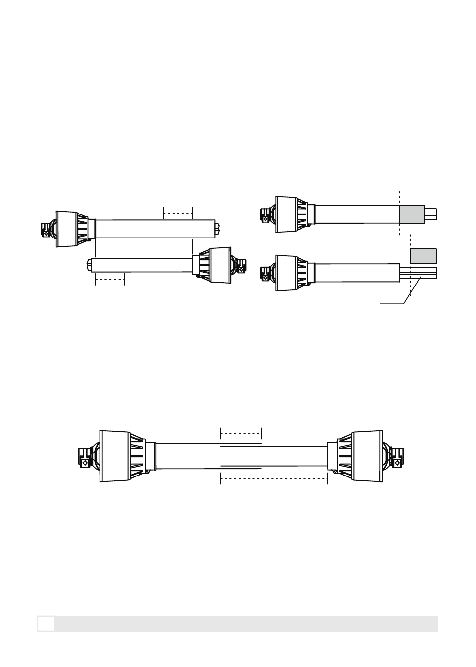
Before operating the mower, ensure that the PTO driveshaft length is suitable. The driveshaft supplied with the
machine is a standard length; therefore, it may need to be shortened or adjusted depending on the tractor used
with the mower.
NOTICE: When checking the minimum PTO driveline length, make sure the tractor PTO driveline and gearbox
input shaft are aligned and level. An excessively long PTO driveline may damage the tractor and implement.
In all operating positions, the minimum overlap of the PTO driveline must be at least 7.09 in. (180 mm). At the
maximum coupling position, the PTO driveline must have a minimum clearance of 0.98 in. (25 mm).
Shortening the PTO driveline
CONNECTION TO THE TRACTOR
7.09 in
0.98 in
A
B
16
3-POINT DRUM MOWER
1.
2.
3.
4.
5.
6.
7. Before reassembling the shaft, clean both ends by removing burrs and beveling the two splined shafts.
Remove all chips and cuttings.
8. Join the two halves of the shaft together.
9. Install the PTO driveline and check that it meets the required operating dimensions described in the previous
section.
NOTE: Make sure the inner and outer splined profiles overlap by at least one-third of the total length (L).
Adjusting the PTO driveline
1. Position the machine as close as possible to the tractor. Secure the tractor, shut off the engine, and remove
the ignition key.
2. Separate the two halves of the PTO driveline. Install the female half onto the tractor PTO and the male half
onto the machine PTO, making sure they are correctly positioned and secured with the locking pins.
3. Place the two shaft halves parallel to each other, as shown in Figure 1.
4. Mark the points where the two shaft halves need to be shortened. Measure 0.98 in. (25 mm) from the starting
point of each half, as shown in Figure 1.
5. Cut the guard cover (A), then use the cut section (B) as a reference to cut the splined shaft (C).
6. Repeat the same procedure for the other half of the shaft.
Note: If you have any problems during assembly or operation, please contact us for technical support.
CONNECTION TO THE TRACTOR
C
1/3
L
0.98 in
0.98 in
B
A
17
3-POINT DRUM MOWER
Checklist Before Operation
Before operating the machine, carefully inspect the following items:
1. Before starting the machine, check and lubricate all grease points on the machine and PTO driveshaft. Check
the oil level in the gearbox and add oil if necessary.
2. Use only an agricultural tractor with horsepower within the specified range for the implement.
3. Make sure the machine is properly attached to the tractor. Ensure that retainers are installed on all mounting
pins.
4. Make sure front ballast weights are installed on the tractor if required.
5. Check that the tractor PTO shaft rotates freely and that the machine driveline telescopes smoothly.
6. Check the blades. Make sure they are not damaged or broken and can swing freely in their mounts. Repair or
replace them if necessary.
7. Check and tighten the blade bolts.
8. Check all rotating parts for entangled material and remove any debris.
9. Install and secure all guards, hooks, and covers before starting the machine.
10. Before installing the PTO shaft, make sure the engine is stopped and the PTO shaft is in safe working
condition.
11. Keep all bystanders away from the area before engaging tractor power.
12. Before cleaning, repairing, or lubricating the machine, stop the engine and remove the ignition key.
13. When the PTO shaft is not connected to the tractor, support it on the frame to keep it from lying in the dirt.
14. Do not approach the machine while it is operating.
15. Before transport, make sure the Adjusting Plate (A) is installed in the second hole and move the Parking Leg
(B) to the transport/storage position. See Figure 12.
16. During operation, adjust the lateral offset/working position of the mower using the holes in the Adjusting
Plate.
OPERATION
OPERATION
Hazard control and accident prevention depend on the awareness, care, good judgment, and proper training
of personnel involved in the operation, transport, storage, and maintenance of the mower.
Therefore, no one should operate this machine without first reading, fully understanding, and becoming
familiar with the Operator’s Manual.
Make sure all operators have completed the checklist below before operating the mower.
Figure 12

18
3-POINT DRUM MOWER
Leveling Adjustment
Leveling adjustments are made using the tractor’s 3-point lower lift arms and top center link.
1. Park the tractor and mower on a flat, level surface.
2. Slowly raise the mower with the tractor’s 3-point hydraulic lift until the unit is approximately 1 to 2 in. above
the ground.
3. Make sure the lower lift arms are stabilized to prevent excessive side-to-side movement.
4. Place a spirit level on the top cover from left to right. Adjust one of the lower 3-point lift arms up or down until
the mower is level from side to side.
5. Adjust the tractor’s top center link so that the upper hitch pin is vertically above, or slightly behind, the lower
hitch pins.
6. Slowly operate the tractor’s 3-point hydraulic control up and down to check for clearance between the tires,
frame, and drawbar.
OPERATION

19
3-POINT DRUM MOWER
General Service
Gearbox Maintenance
The recommended maintenance intervals are based on normal operating conditions. Severe or unusual operating
conditions may require more frequent service.
Every 4 Hours of Operation
• Check and tighten all nuts and bolts.
• Inspect for oil leaks around the housing, seals, flanges, and fittings. Check beneath the gearbox for oil
accumulation.
After the First 50 Hours of Operation
• Drain and replace the gearbox oil after the first 50 hours of operation.
• After the initial oil change, replace the gearbox oil every 250 hours.
Drain the oil from the gearbox completely. Check and clean the gearbox, then fill it with new gear oil to the
specified oil level. For the recommended gearbox oil capacity and oil type, see Specifications.
The draining procedure is as follows:
1. Remove the drain plug from the oil outlet and allow the oil to drain completely.
2. After the oil has drained, reinstall the drain plug.
3. Remove the inspection port bolt and sealing ring.
4. Fill the gearbox with gear oil until the oil begins to overflow from the inspection port, then stop filling.
5. Reinstall the inspection port bolt and sealing ring.
PTO Shaft Maintenance
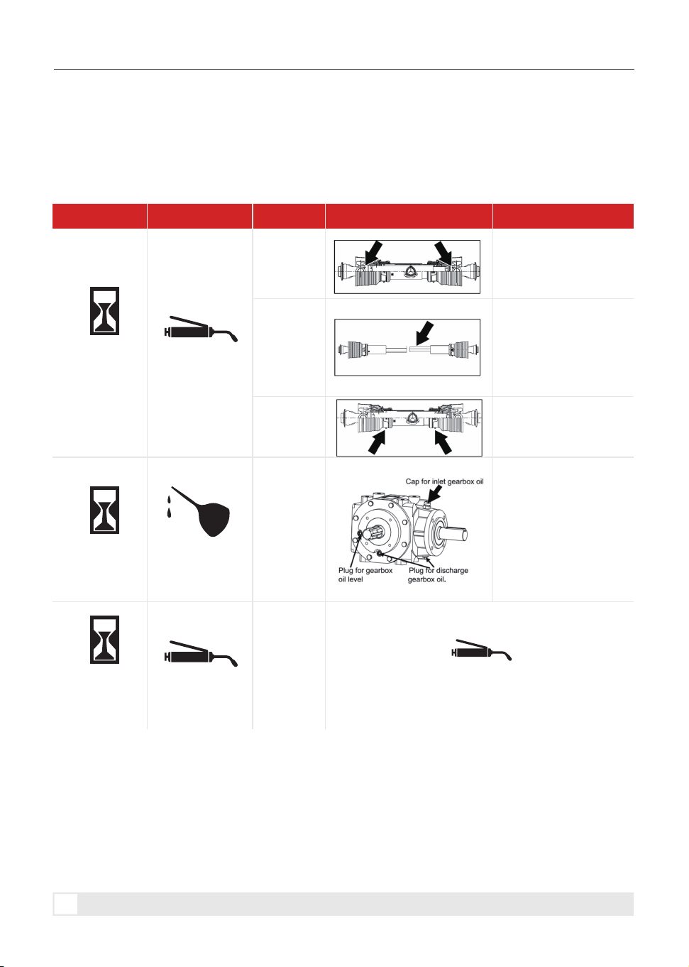
During heavy use, it is recommended to lubricate the PTO shaft with multi-purpose grease every 8 to 10 hours of
operation.
The PTO shaft is designed to telescope to accommodate dimensional changes as the machine moves through
its operating range. A tubular guard encloses the drive components and is designed to rotate independently of
them. The shaft should telescope smoothly, and the guard should rotate freely on the shaft at all times.
Annual disassembly, cleaning, and lubrication are recommended to ensure that all components function
properly.
To maintain the PTO shaft, follow these steps:
1.Remove the PTO shaft from the machine.
2.Pull the shaft apart.
3.Use a screwdriver to pry the tabs out of the sleeves on each end.
4.Pull the shaft out of the plastic tubular guard.
5.Use solvent to clean the male and female telescoping sections.
6.Apply a light coat of grease to each section.
7.Clean the grooves on each end where the tabs are located, and clean each tab as well.
8.Apply a light coat of grease to each groove.
9.Insert the shaft into its corresponding guard and align the slots with the groove.
10.Insert the tabs through the slots and seat them in the groove.
11.Check that each guard rotates freely on the shaft.
12.Reassemble the shaft.
SERVICE AND MAINTENANCE
SERVICE AND MAINTENANCE
20
3-POINT DRUM MOWER
Lubrication Parts
Lubrication parts list:
Multi-purpose
Grease
Driveline
Shaft U
Joints
Quantity - 4 to 8 Pumps
Quantity - As Required
Quantity - Clean & coat
inner profile tube of
driveline with a light film
of grease and then
reassemble.
Do not overfill!
If the gearbox requires
service, contact an
authorized MechMaxx
dealer or service center.
Driveline
Profiles
Inner Tube
Bearings
Gearbox
13.Check that the shaft telescopes smoothly.
14.Replace any damaged or worn components.
15.Install the PTO shaft on the machine.
SERVICE AND MAINTENANCE
Multi-purpose
Grease
Other parts
If the GREASE labels ( ) are posted on the
machine, you need to lubricate it regularly.
Recommended lubrication interval: every 25 hours.
25
HOURS
25
HOURS
Type of
Lubrication:
85w/90
AS
REQUIRED
INTERVAL TYPE NAME PARTS IMAGE
REMARK
21
3-POINT DRUM MOWER
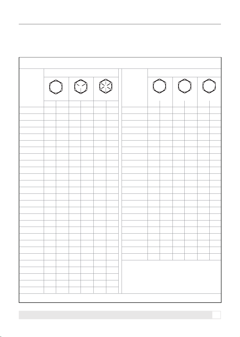
The tables shown below give correct torque values for various bolts and cap screws. Tighten all bolts to the torques
specified unless otherwise noted. Check tightness of bolts periodically, using bolt torque chart as a guide. Replace
fasteners only with fasteners of the same size, thread pitch, length, and property class or grade.
Torque tolerance +0%,-15% of torquing values. Unless otherwise specified use torque values listed above.
1
in-tpi = nominal thread diameter in inches-threads per
inch
2
N.m= newton-meters
3
ft-lb= foot pounds
4
mm x pitch = nominal thread diameter in millimeters x
thread pitch
TORQUE VALUES CHART FOR COMMON BOLT SIZES
Grade 2 Grade 5
Bolt Head Identification Bolt Head Identification
Grade 8 Class 5.8 Class 8.8 Class 10.9
Bolt Size
(Inches)
in-tpi
1
Bolt Size
(Inches)
mm x pitch
4
N.m
2
N.m
ft-lb
3
ft-lb
N.m
ft-lb
N.m
ft-lb
N.m
ft-lb
N.m
ft-lb
1/4"-20
1/4"-28
5/16"-18
5/16"-24
3/8" -16
3/8" -24
7/16" -14
7/16"-20
1/2" -13
1/2" -20
9/16"-12
9/16"-18
5/8" - 11
5/8" -18
3/4" -10
3/4" -16
7/8" -9
7/8" -14
1"-8
1"-12
1-1/8"-7
1-1/8" -12
1-1/4"-7
1-1/4" -12
1-3/8"-6
1-3/8" -12
1-1/2" -6
1-1/2" -12
M5X0.8
M6X1
M8X 1.25
M8X1
M10X 1.5
M10X0.75
M12X 1.75
M12X 1.5
M12X1
M14 X2
M14 X 1.5
M16X2
M16X 1.5
M18 X 2.5
M18 X 1.5
M20 X 2.5
M20 X 1.5
M24X3
M24 X2
M30 X 3.5
M30×2
M36 X3.5
M36X2
4
7
17
18
33
39
58
60
90
92
99
145
155
195
220
280
310
480
525
960
1060
1730
1880
3
5
12
13
25
29
42
44
66
68
73
105
115
145
165
205
230
355
390
705
785
1270
1380
6
11
26
28
52
61
91
95
105
145
155
225
240
310
350
440
650
760
830
1510
1680
2650
2960
5
8
19
21
39
45
67
70
77
105
115
165
180
230
260
325
480
560
610
1120
1240
1950
2190
9
15
36
39
72
85
125
130
145
200
215
315
335
405
485
610
900
1050
1150
2100
2320
3660
4100
7
11
27
29
53
62
93
97
105
150
160
230
245
300
355
450
665
780
845
1550
1710
2700
3220
7.4
8.5
15
17
27
31
43
49
66
75
95
105
130
150
235
260
225
250
340
370
480
540
680
750
890
1010
1180
1330
5.6
6
11
13
20
22
32
36
49
55
70
79
97
110
170
190
165
185
250
275
355
395
500
555
655
745
870
980
11
13
24
26
42
47
67
75
105
115
150
165
205
230
360
405
585
640
875
955
1080
1210
1520
1680
1990
2270
2640
2970
8
10
17
19
31
35
49
55
76
85
110
120
150
170
265
295
430
475
645
705
795
890
1120
1240
1470
1670
1950
2190
16
18
33
37
59
67
95
105
145
165
210
235
285
325
510
570
820
905
1230
1350
1750
1960
2460
2730
3230
3680
4290
4820
12
14
25
27
44
49
70
78
105
120
155
170
210
240
375
420
605
670
910
995
1290
1440
1820
2010
2380
2710
3160
3560
8.85.8 10.9
Tightening Torque
SERVICE AND MAINTENANCE
22
3-POINT DRUM MOWER
• This chart is an approximate estimate of torque values.
• Always tighten hardware to these values unless a different torque value or tightening procedure is listed for a
specific application.
• Fasteners must always be replaced with the same grades as specified in the manual.
• Always use the proper tool for tightening hardware; SAE for SAE hardware and Metric for Metric hardware.
• Make sure that fastener threads are clean and that you properly start thread engagement.
Replacing the Blade
Frequently check the drum to make sure they are in good working condition and properly secured to the blade
disc.
Replace any worn or damaged blades with new ones.
Frequently inspect the blades and blade discs to make sure they are in good condition and properly secured.
Replace any worn, bent, cracked, or damaged blades. Replacement blades must match the original blades in size
and weight to maintain proper blade-disc balance. Use only genuine or manufacturer-approved replacement
blades.
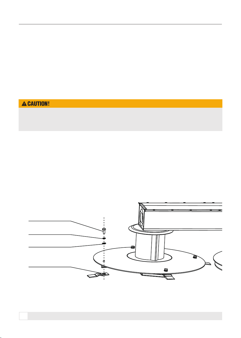
Replacement Steps
1. Remove the full-thread hex head bolt M10×20, spring washer 10, and flat washer 10.
2. Replace the worn blade with a new one.
3. Reinstall the bolt and tighten it to the specified torque.
Note: It is recommended to apply thread-locking compound to the bolt before installation.
Note: If the images shown in the figure above differ from the actual machine, please refer to the actual machine.
SERVICE AND MAINTENANCE
Flat Washer 10
Spring Washer 10
Hex Head Bolt M10×20
Blade
Make sure replacement blades are of the same weight as the original blades to maintain proper blade disc
balance during operation.
Use original factory replacement blades whenever possible.
23
3-POINT DRUM MOWER
Storage
Before storing the implement, follow the steps below:
1. Remove any dirt and grease that may have accumulated on the mower and moving parts. Scrape off
compacted dirt from under the hood. Clean the machine inside and out to help prevent corrosion.
2. Check the blade discs/drums, blades, blade mounting points, and blade fasteners for wear or damage.
Replace damaged parts as necessary.
3. If cleaning the machine with a high-pressure washer, do not spray water directly onto the rolling bearings.
4. Check and clean the PTO driveline universal joints and guards. Lubricate the required points and replace any
worn or damaged components.
5. Repaint any scratched or damaged surfaces to prevent corrosion.
6. Store the machine in a dry, level area.
Before transporting the implement, follow the steps below:
1. When raising the mower to the transport position, make sure the driveline does not contact the tractor or
mower. If necessary, adjust and set the tractor 3-point lift height to limit mower movement and protect the
driveline.
2. Reduce tractor ground speed when turning. Allow enough clearance to prevent the mower from contacting
obstacles such as buildings, trees, fences, or other objects.
3. Select a safe travel speed when transporting the mower from one area to another. When traveling on
roadways, operate in a manner that allows faster-moving vehicles to pass safely.
4. When traveling over rough or hilly terrain, shift the tractor to a lower gear.
Transport
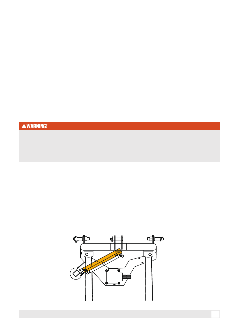
5. In the transport position, the safety plate must be inserted into place, as shown in Figure 13.
STORAGE AND TRANSPORT
STORAGE AND TRANSPORT
Always disengage the PTO before raising the mower to the transport position.
When traveling on public roads, make sure all required tractor/implement lighting, reflectors, and slow-mov-
ing vehicle identification are installed, clean, visible, and used as required by applicable law.
Always comply with all applicable federal, state, and local laws.
Figure 13

24
3-POINT DRUM MOWER
The troubleshooting list below includes common problems that may or may not apply to the machine described
in this manual.
If you encounter a problem that is not covered in this list, please contact us for technical support.
TROUBLESHOOTING
TROUBLESHOOTING
MALFUNCTION
SOLUTIONPOSSIBLE CAUSE
Significant machine
vibration
Worn blades
Missing
Broken blades
Worn blade-disc/drum support bearings
Blade discs/drums fouled with debris
Loose parts
Incorrect power take-off speed
Blades touching the ground
Ground speed too high
Cut height too low
Clogging
Excessive build-up of material under the
head
Replace the blades
Replace the bearings.
Reduce the speed
Adjust cut height
Clean under the hood and remove
accumulated material from the cutting area.
Remove debris and clean the cutting assembly.
Tighten bolts and fasteners
Select correct tractor power take-off speed
Check and, if necessary, adjust cut height.
Clean the machine to remove accumulated
debris
Excessively rapid
blade wear
Blades tear rather
than cut, shredded
material not
distributed evenly
Apply grease as indicated in the
Maintenance section
Apply grease as indicated in the
Maintenance section
Reduce the operating angle
Avoid overloading and do not start
the machine when loaded
Replace bearings
Do not exceed 25 degrees
Insufficient greasing
Insufficient greasing
Operating angle incorrect
Overloading
Worn trunnion bearing
Exceeds 25 degrees
Excessive driveline
noise
Driveline wear

25
3-POINT DRUM MOWER
MALFUNCTION SOLUTIONPOSSIBLE CAUSE
Breakage or
deformation of the
driveline
Gearbox overheating
Overloading
Low gearbox oil level
Incorrect oil type
Excessive oil
Overloading
Operating angle incorrect
Avoid overloading and do not start the
machine when loaded
Observe the prescribed speed and power
conditions
Reduce the operating angle
Check for leaks and damaged seals/gaskets.
Repair as necessary and refill to the
specified oil level.
Replace with the prescribed type of oil
Restore correct oil level
TROUBLESHOOTING
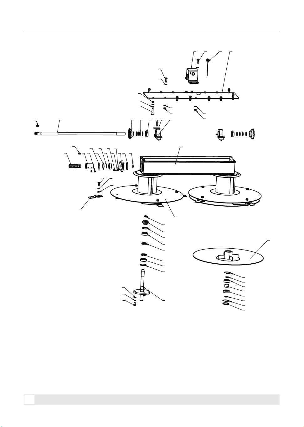
PARTS DIAGRAM
26
3-POINT DRUM MOWER
1
2
3
4
6
5
7
8
9
10
27
12
11
14
13
15
16
17
18
19
20
20
21
22
22
18
19
19
18
23
24
25
26
28
28
35
36
31
30
31
32
34
33
37
38
39
29
30
31
32
18
22
19
19
22
18
35
36
31
32
31
31
PARTS DIAGRAM

27
3-POINT DRUM MOWER
NO.
DESCRIPTION
QTY.
1
2
3
4
5
6
7
8
9
10
11
12
13
14
15
16
17
18
19
20
21
22
23
24
25
26
27
28
29
30
31
32
33
34
Gearbox Weldment
Gearbox Top Plate Weldment
Pivot Shaft Weldment
Lug Weldment
Turntable Weldment
Bottom Turntable Weldment
Bearing Housing
Drive Shaft
Coupling
Drive Shaft Head
Spacer
Bearing Seat
Bevel Gear M5 Z10
Bevel Gear M5 Z17
Plug Cap
Locking Washer
Cylindrical Roller Bearing
Circlip for Hole 52
Deep Groove Ball Bearing
Skeleton Oil Seal
Skeleton Oil Seal
Circlip for Shaft 25
Oil Dipstick
Nylon Insert Lock Nut
Blade
O-Ring
Adjusting Shim
Parallel Key
Hex Socket Set Screw with Dog Point, M10×12
1
1
2
1
2
2
1
1
1
1
2
2
2
2
2
4
1
9
10
4
1
6
1
2
8
1
8
2
2
Hex Head Bolt, Fully Threaded, M10×30
Flat Washer 10
Hexagon Thin Lock Nut with Non-Metallic Insert, M10
Hex Head Bolt, Fully Threaded, M10×35
Hex Head Bolt, Fully Threaded, M10×50
12
48
16
4
4
PARTS DIAGRAM
28
3-POINT DRUM MOWER
NO.
DESCRIPTION
QTY.
Hex Head Bolt, Fully Threaded, M10×20
Spring Washer 10
Hex Socket Head Cap Screw, M6×20
Spring Washer 6
Flat Washer 6
16
16
4
4
4
1
32
4
6 8 8 7
9
10 11
6887
5
35
36
37
38
39
PARTS DIAGRAM

29
3-POINT DRUM MOWER
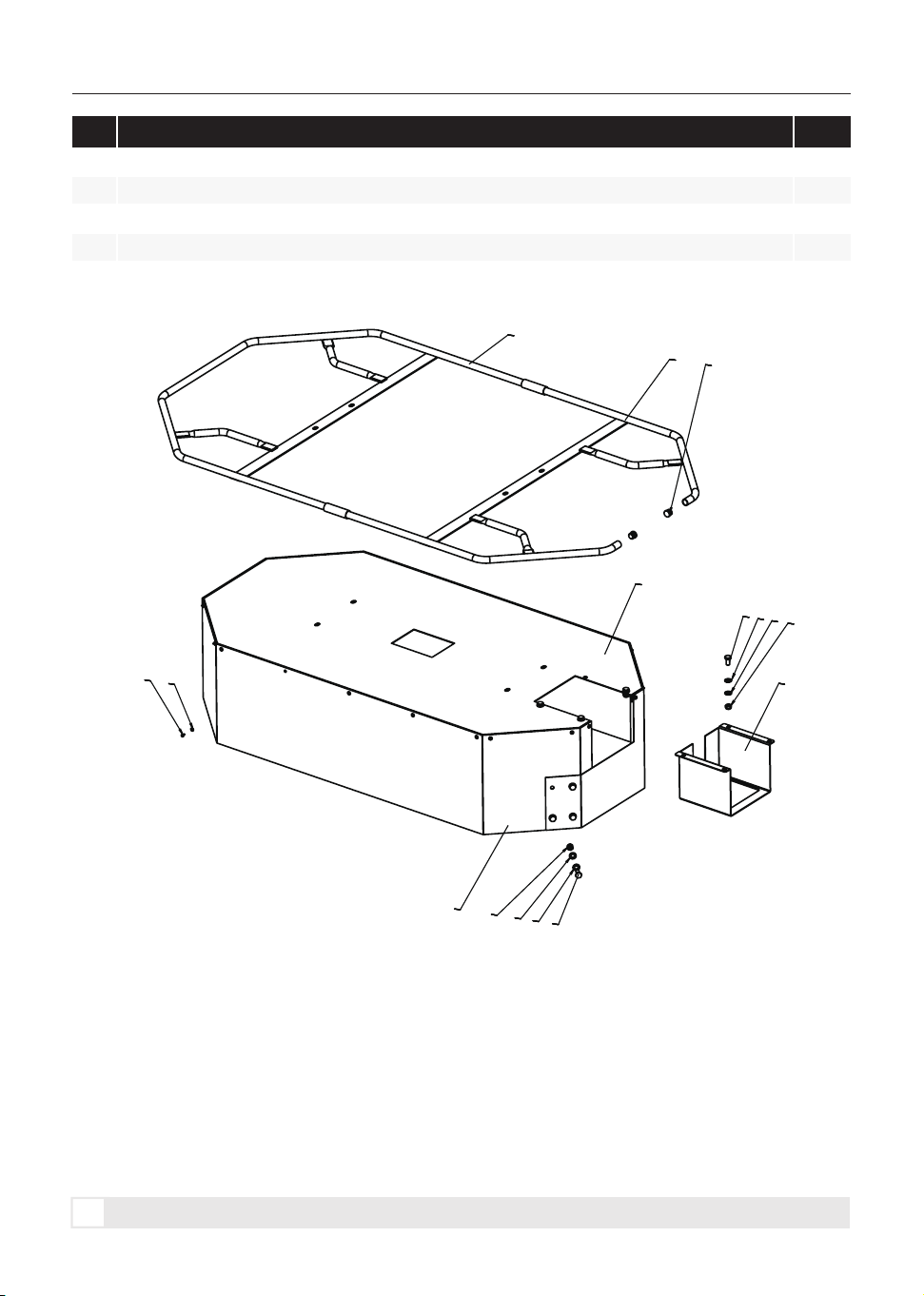
NO.
DESCRIPTION
QTY.
Top Guard Weldment
Guardrail Weldment 1
Guardrail Weldment 2
Guard
Skirt
Hex Head Bolt, Fully Threaded, M10×20
Hexagon Lock Nut with Non-Metallic Insert, M10
Flat Washer 10
Round Tube Plug
Rivet
Flat Washer 5
1
2
3
4
5
6
7
8
9
10
11
1
1
1
1
1
8
8
16
2
22
22
PARTS DIAGRAM
30
3-POINT DRUM MOWER
1
2
3
3
4
5
67
7
8
9
10
11
12
14
13
15
16 17
17 18
19
2021
17
16
15
10
PARTS DIAGRAM

31
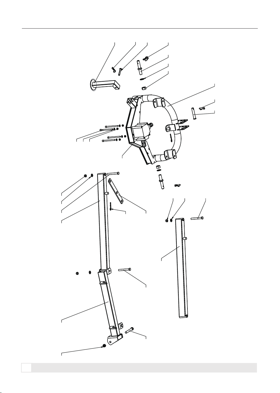
3-POINT DRUM MOWER
NO.
DESCRIPTION
QTY.
1
2
3
4
5
6
7
8
9
10
11
12
13
14
15
16
17
18
19
20
21
Hitch Weldment
Parking Leg
Linkage Weldment 1
Linkage Weldment 2
Adjusting Plate
Drawbar Pin
Ring Cotter Pin
Pin Shaft, 16×105
Pin Shaft, 12×70
Type B Pin, M3.5×75
Gearbox
Hex Socket Head Cap Screw, Half Thread, M10×130
Hexagon Lock Nut with Non-Metallic Insert, M10
Flat Washer 10
Hexagon Lock Nut with Non-Metallic Insert, M14
Flat Washer 14
Hex Head Bolt, Fully Threaded, M14×120
Hex Head Bolt, M16×120
Hexagon Lock Nut with Non-Metallic Insert, M16
Hexagon Lock Nut with Non-Metallic Insert, M22
Flat Washer 22
1
1
2
1
1
2
3
1
1
3
1
4
4
4
4
4
4
1
1
2
2
PARTS DIAGRAM



RELIABLE EFFICIENT VALUE
315-750-4008
Our company is committed to continuous product improvement. The actual
product may differ from the pictures or descriptions in this manual. Specifica-
tions and design are subject to change without prior notice.
www.mechmaxx.com