Item #XXXXXXX
Model #SW1787 MBK
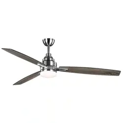
ALDERBROOK LED 60 INCH CEILING FAN
Attaching the decorative cover
Attaching the Blade Arm
Attaching the Fan Blades
Hanging the Fan
To reduce the risk of fire or electric shock, this
fan should only be used with fan speed control part
NO.:DL-1170FCS-08, manufactured by: Summer Wind
International. ,Ltd.
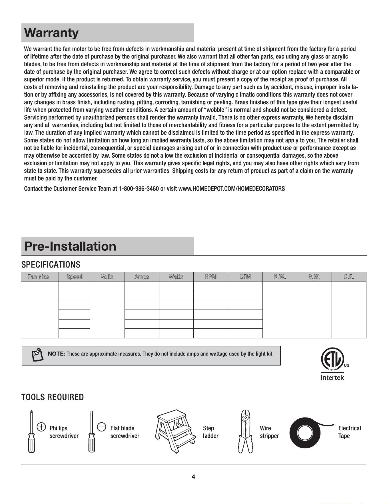
60 in.(1,52 m)
120
Fan
size Watts RPM CFMSpeed Volts Amps N.W. G.W. C.F.
1.78’ ft.
5.42kgs
(11.92 lbs)
6.6 kgs
(14.52lbs)
0.04
0.05
0.07
0.12
0.18
0.28
2.01
2.78
4.13
6.31
9.64
16.91
44
65
85
105
125
153
1381
2106
2877
3684
4411
5416
1
2
3
4
5
6
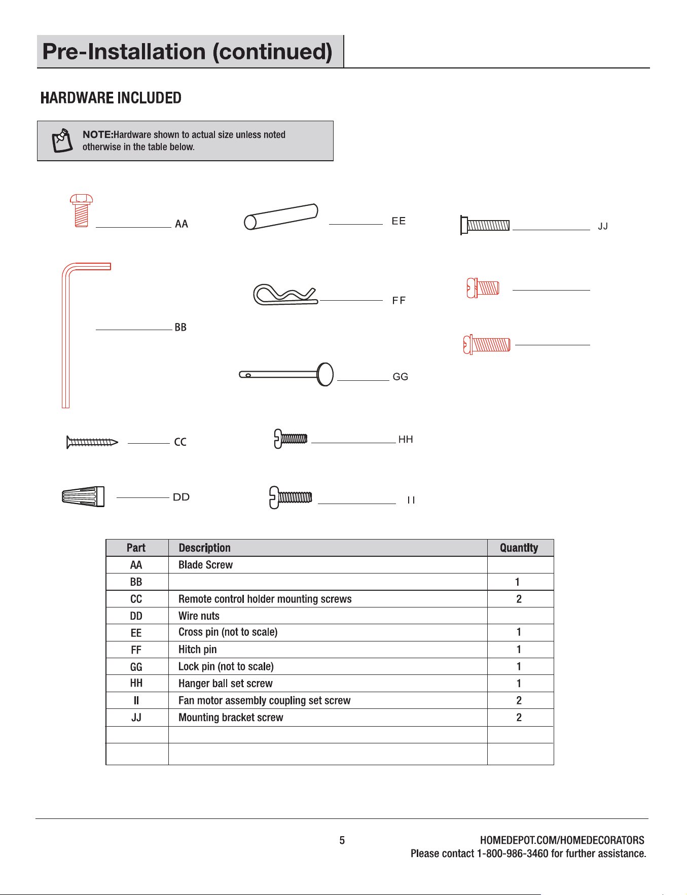
KK
LL
KK
LL Blade arm screw (pre-assembled)
Decorative cover screw
Allen wrench
7
5
2
(pre-assembled)
(pre-assembled)
(pre-assembled)
(pre-assembled)
(pre-assembled)
(pre-assembled)
7
Decorative Cover
Blade arm
(pre-assembled)
(pre-assembled)
2
2
I
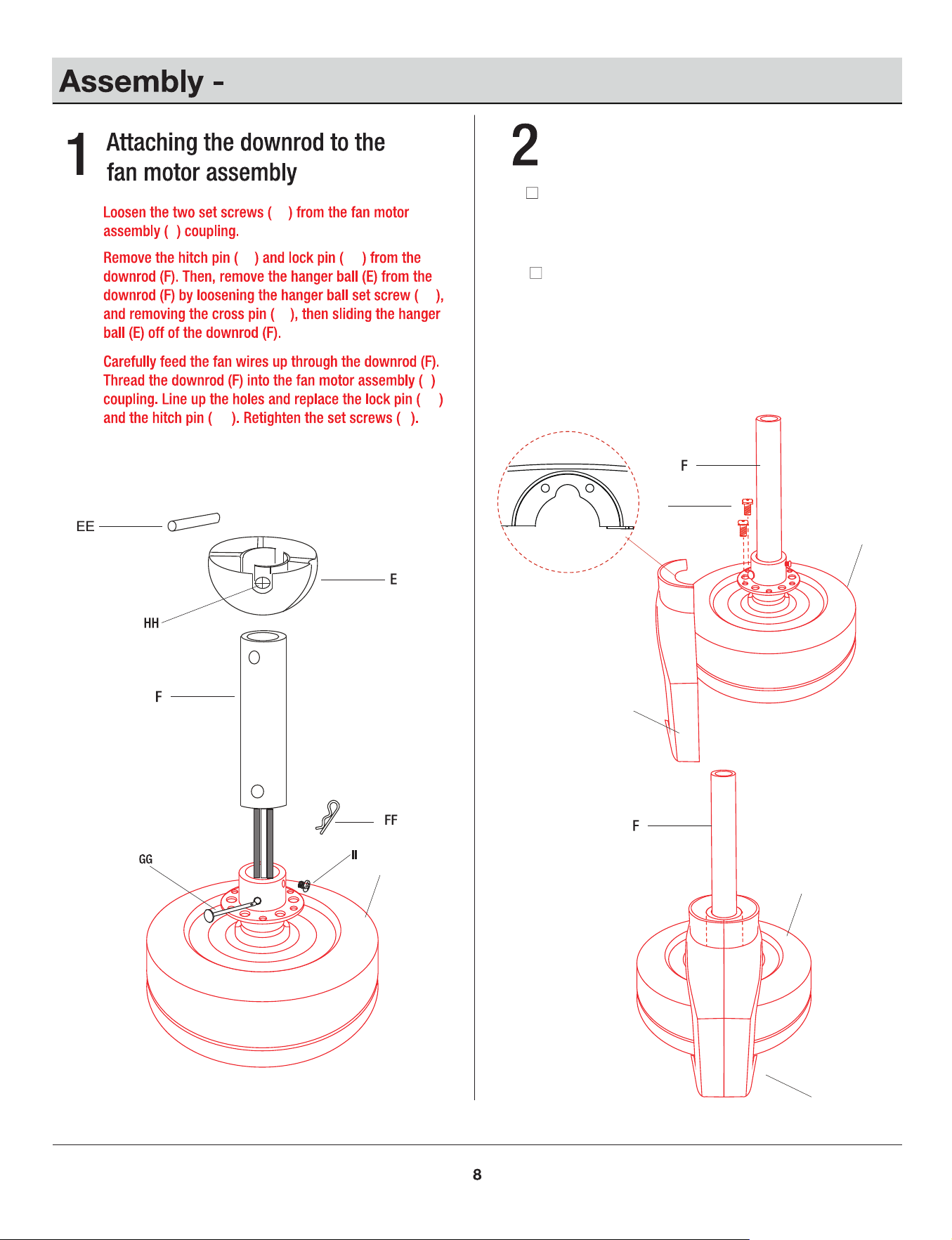
Attaching the decorative cover
□
II
□
□
II
FF GG
HH
EE
GG
FF
I
I
KK
I
I
G
G
Attaching the decorative cover
Attach the decorative covers (G) to the coupling of the
fan motor assembly (I) by using the decorative cover
screws (KK) . Ensure all the screws (KK) are tightened.
Repeat process for the other decorative cover(G)
LL
I
H
G
I
G
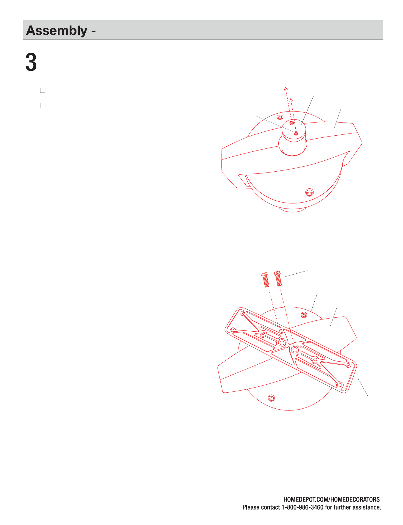
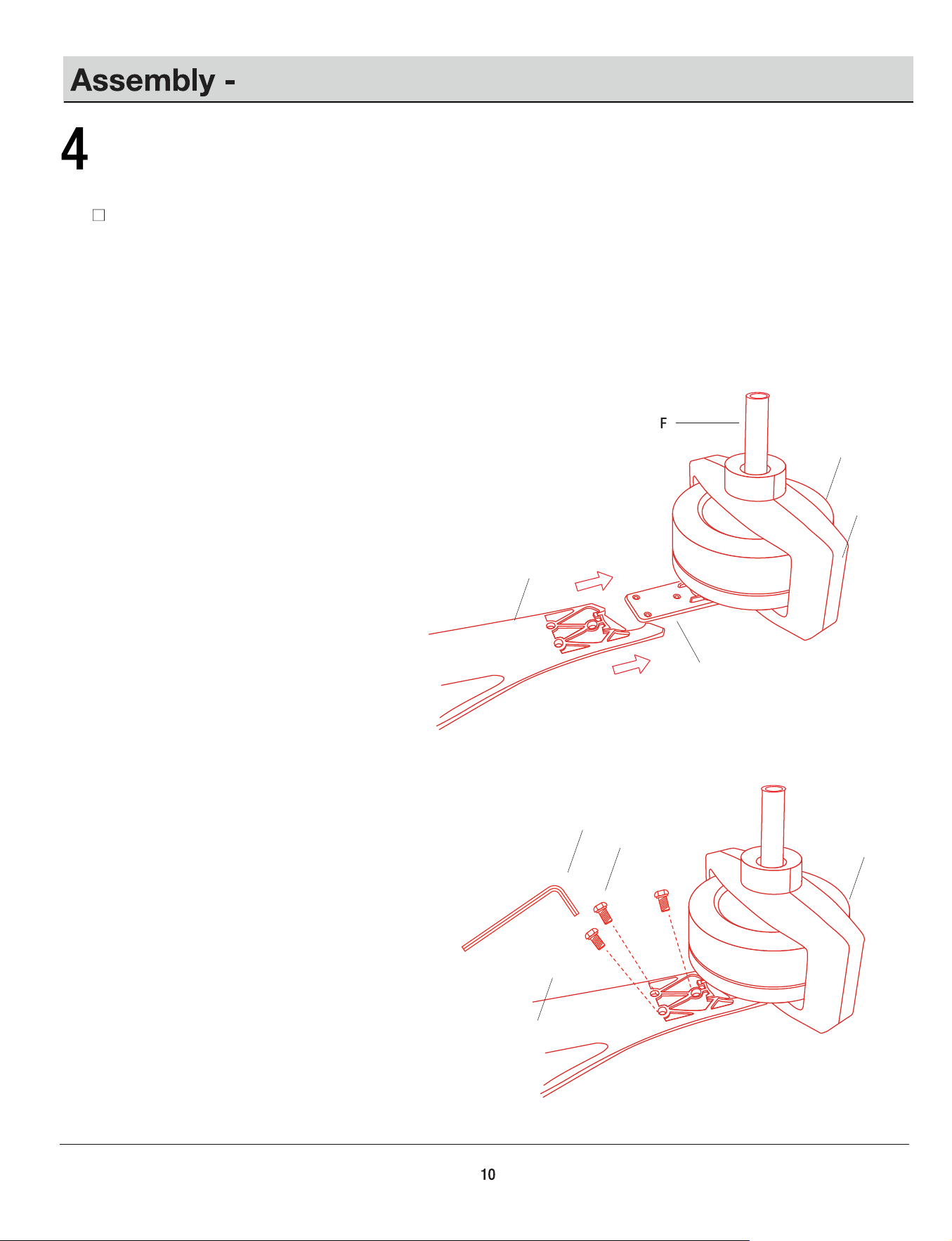
Attaching the Blade Arm
Attaching the blade arm to fan motor assembly
Remove the blade arm screws (LL) from the fan motor assembly (I).
9
LL
Align the holes in the bottom of the fan motor assembly (I)
and the blade arm (H), and secure with the blade
arm screws (LL). Ensure all the screws (LL) are tightened.
AA
BB
A
I
G
H
A
I
Attaching the Fan Blades
Fastening the blades to blade arm
Attach the blade (A) to the blade arm (H) by using the blade
screws (AA). Tightened all the screws (AA) by using the
Allen wrench (BB).
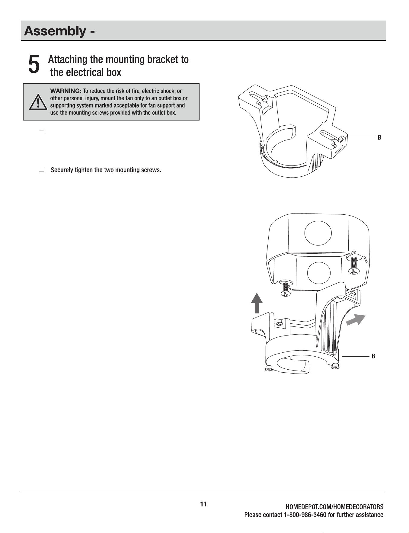
Hanging the Fan
Place the slots from the mounting bracket (B) over the two
screws provided with the outlet box.slide the mounting
bracket (B) until it locks in place at the narrow section
of the slots.
G
A
I
G
A
I
MM
MM
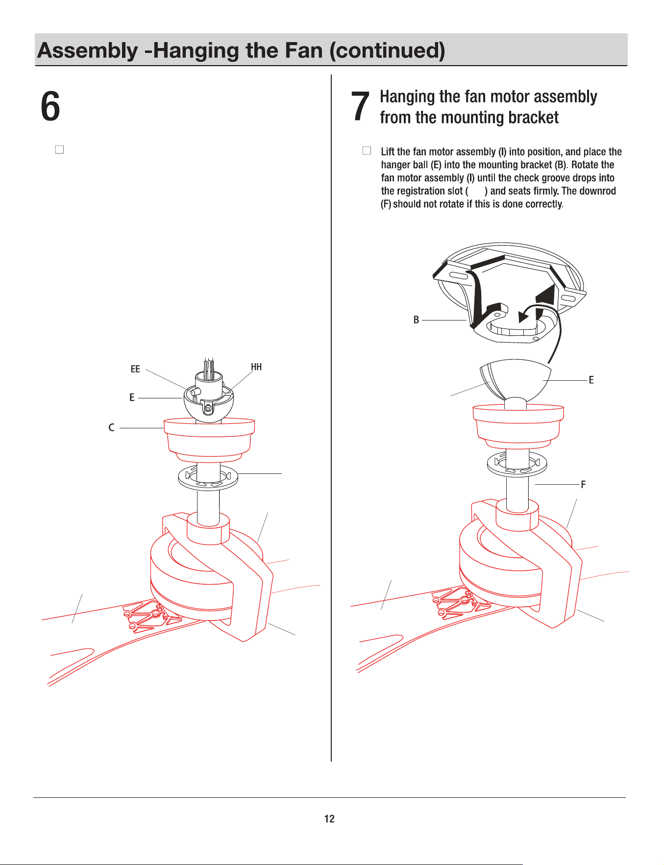
Slip the canopy cover (D), and canopy (C) onto the
downrod (F).Carefully reinstall the hanger ball (E) onto
the downrod (F), and ensure that the cross pin (EE) is in
the correct position, the set screws (HH) are tight, and
the wires are not twisted.
D
Attaching the canopy cover, and
canopy to the downrod
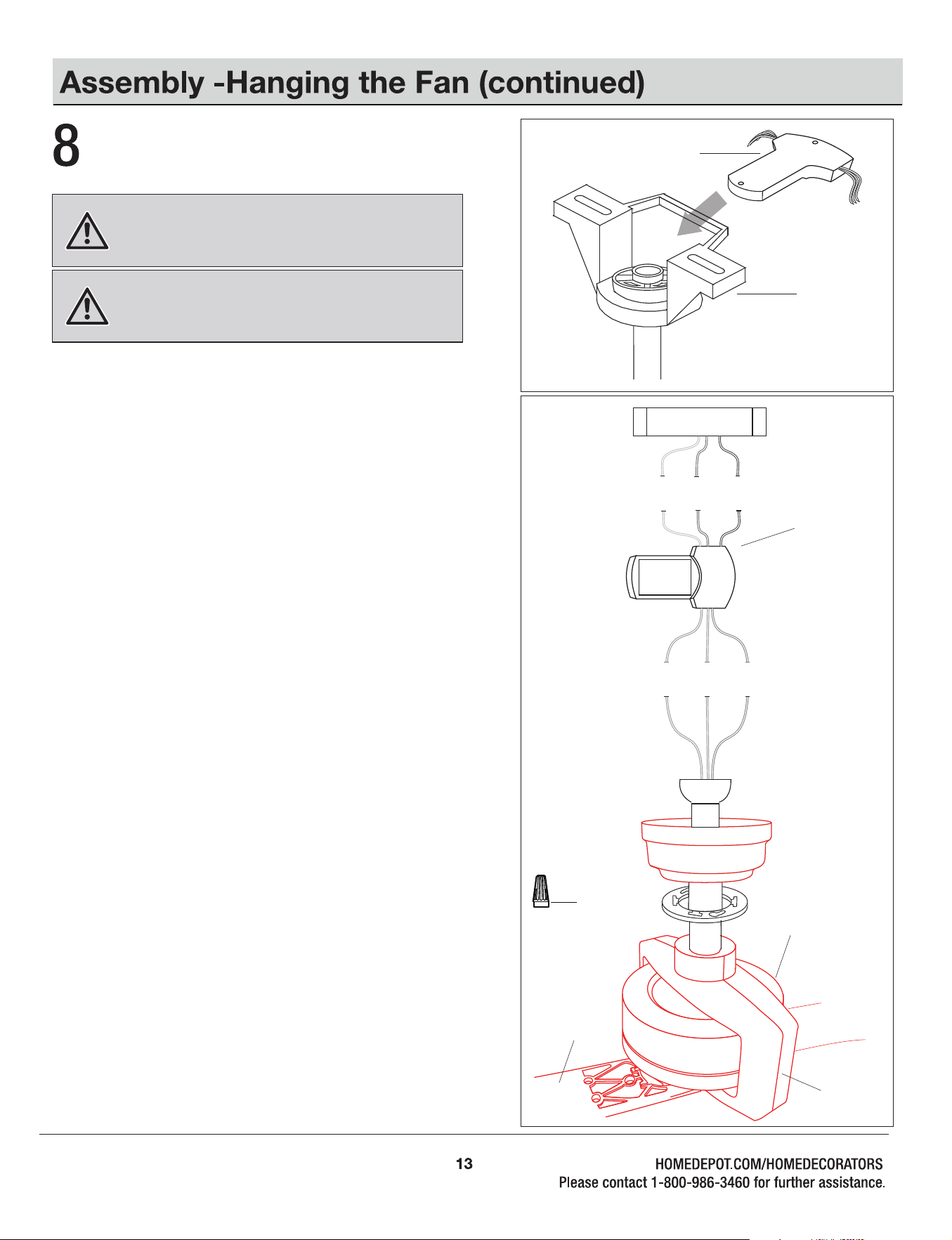
Making the electrical connections
WARNING: To avoid possible electrical shock, ensure the
electricity is turned off at the circuit breaker or main fuse box
before wiring.
WARNING: Check to see that all connections are tight,
including the ground, and that no bare wire is visible at the
wire nuts, except for the ground wire.
Motor to Receiver Electrical Connections:
Connect the YELLOW wire from the fan to the YELLOW wire
marked “MOTOR 1” from the Receiver.
Connect the RED wire from the fan to the RED wire marked
“MOTOR 2” from the Receiver.
Connect the GREY wire from the fan to the GREY wire marked
“MOTOR 3” from the Receiver.
Receiver to House Supply Wires Electrical connections:
Connect the WHITE wire (Neutral) from the outlet box to the
WHITE wire marked ”AC in N” from the receiver.
Connect the BLACK wire (Hot) from the outlet box to the BLACK
wire marked “AC in L” from the receiver.
If your outlet box has a GROUND wire (Green or Bare
Copper),connect this wire to the Hanger Ball and Hanger
Bracket and receiver Ground wires.
If your outlet box does not have a Ground Wire, then connect the
Hanger Ball and Hanger Bracket and Receiver Ground Wire
together.
Secure wire connection with the plastic wire nuts (DD)
provided. Especially , for the ground wires, please use bigger wire
nut (DD) provided.
After all splices are made, check to make sure there are no
loose strands.
□
□
□
□
□
Note: Fan must be installed from a maximum distance of 40 feet
(12.2 m) from the transmitting unit for proper signal transmission
between the transmitting unit and the fan’s receiving unit.
Insert the receiver (J) into the mounting bracket (B) with the flat
side of the receiver (J) facing the ceiling.
Follow the steps below to connect the fan to your house supply
wires. Secure the wire nuts supplied with your fan by wrapping the
connections with electrical tape.
G
A
I
J
B
J
Outlet Box
Yellow
Yellow
Red
Red
Grey
Grey
Black
Black
Green
Green
White
White
DD (x7)
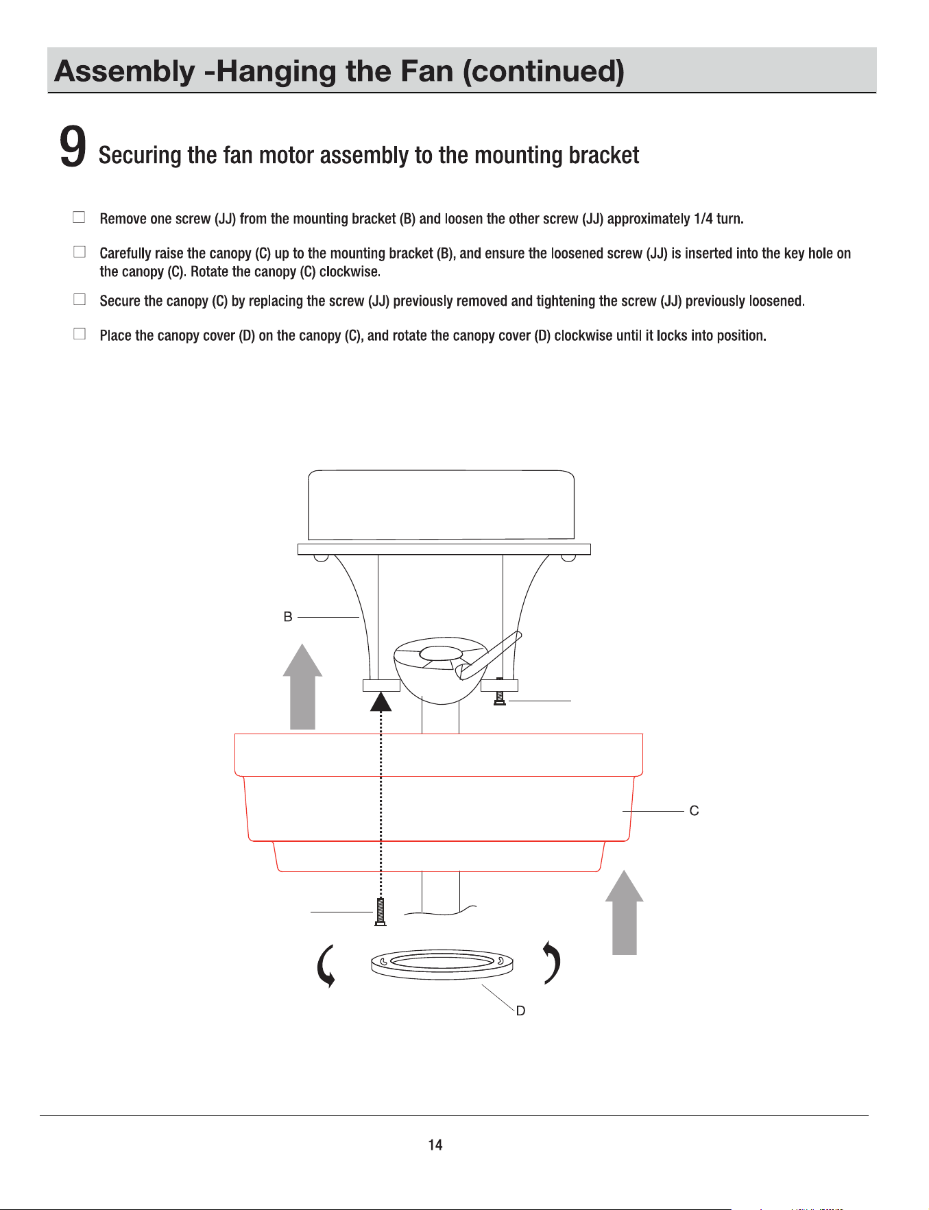
JJ
JJ
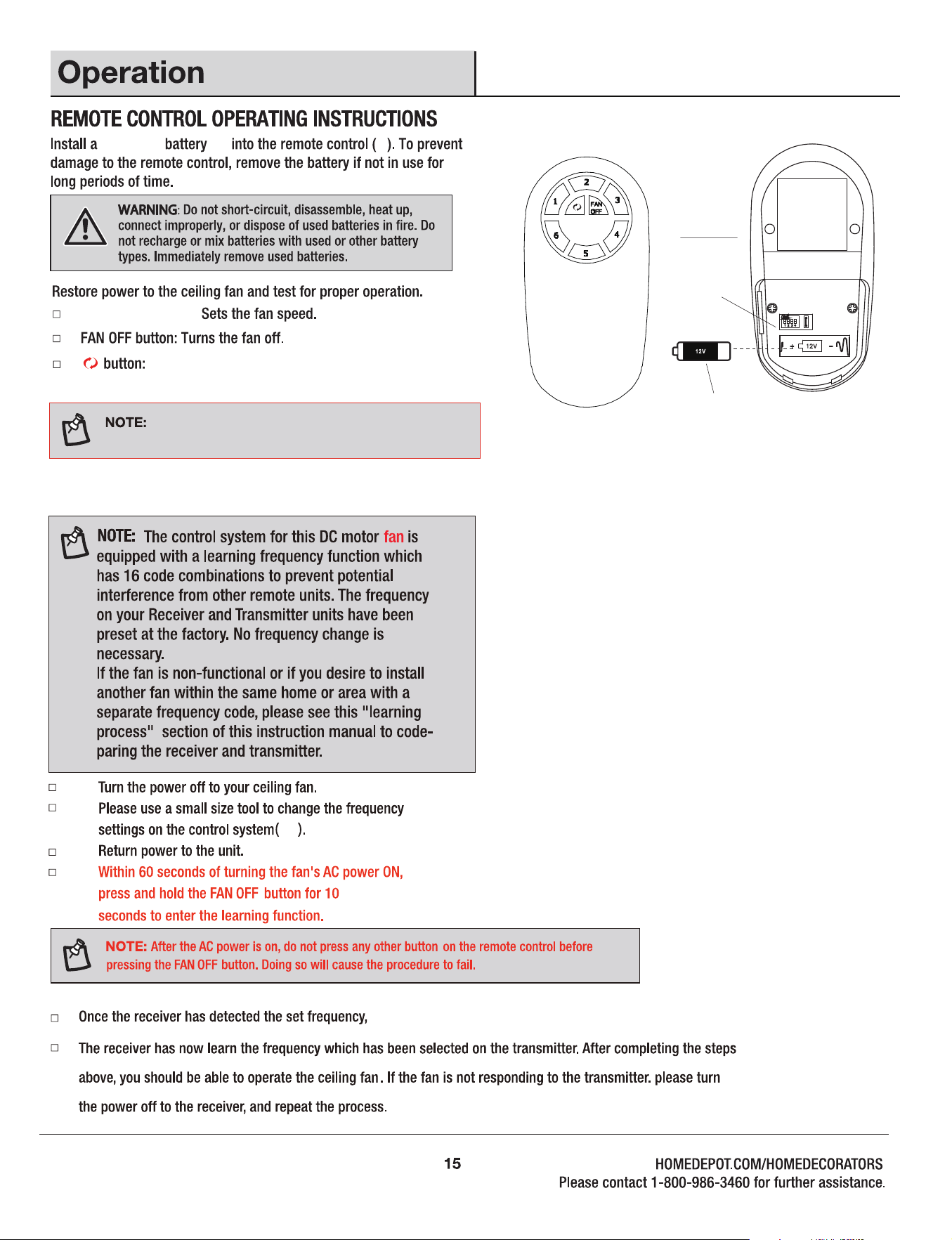
K
M
(M)
K
1.2.3.4.5.6 buttons:
NN
NN
Learning process
A23G 12V
the fan will begin to rotate for a short period and then shut off.
Controls the fan direction.
To change the direction of the rotation of the blades
the fan muse be in operation.
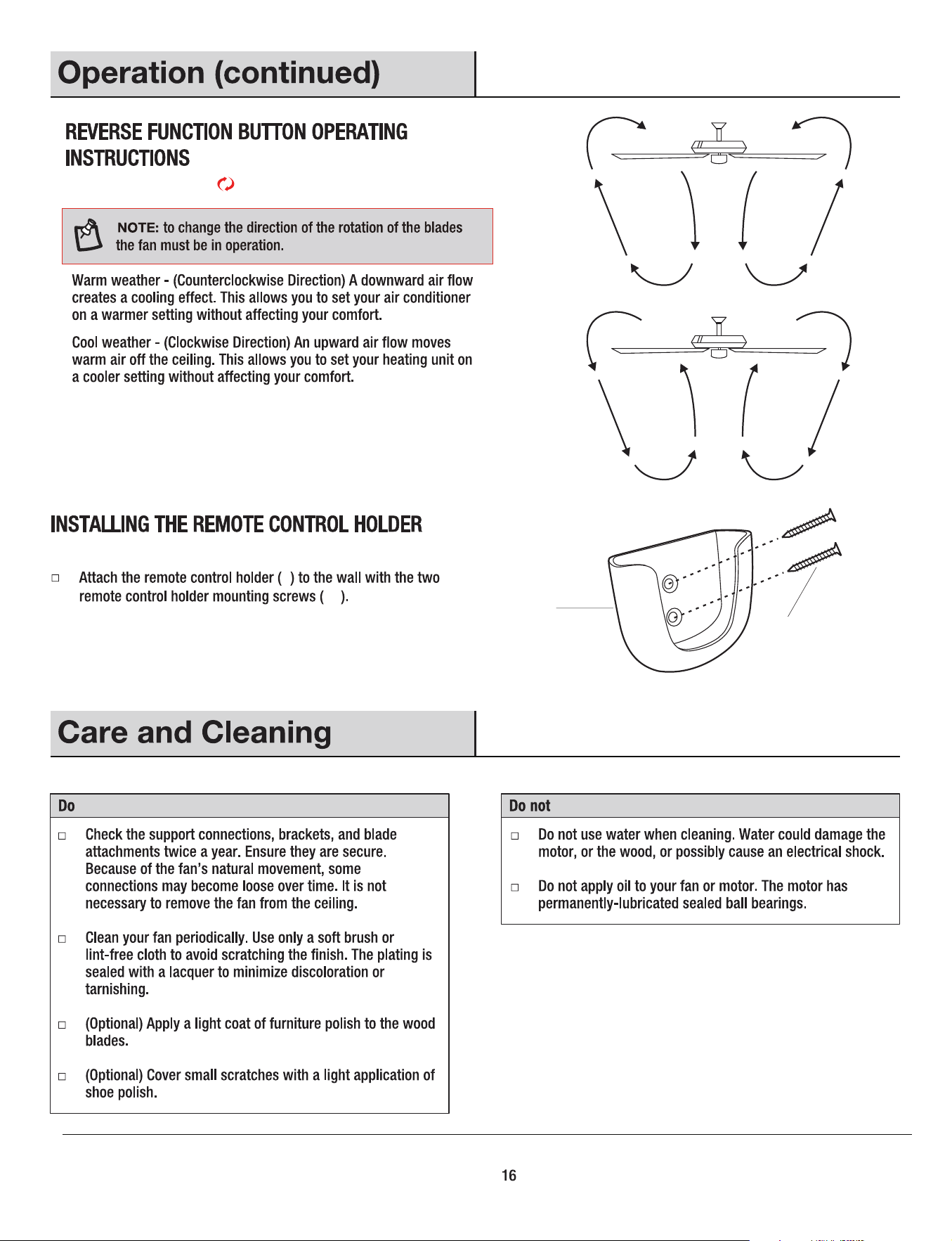
L
L
Reverse function button : Controls the fan direction.
CC
CC
13
KK
LL
Decorative Cover
Blade arm
KK
LL Blade arm screw
Decorative cover screw
Allen wrench
18