USE AND CARE GUIDE
FLUSH MOUNT CEILING LIGHT WITH MOTION SENSOR
NOTE: Keep your receipt and these instructions for proof of purchase.
WARNING: RISK OF ELECTRIC SHOCK. Ensure the electricity to the wires you are working on is shut off. Either remove the
fuse or turn off the circuit breaker before removing an existing light xture or installing the new one.
If you are unfamiliar with electrical installations, we recommend you contact a qualied electrician to do the installation.
INSTALLATION
Select a suitable location that can support the weight of the xture. Determine the method for mounting the xture before
drilling, based on the type of ceiling.
1.
T
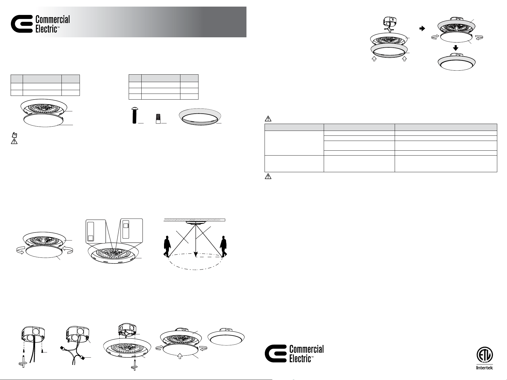
urn counterclockwise to open the diffuser shade (B) to expose the mounting holes.
Customize the color temperature and motion sensor’s detection range of the light.
¤ Choose your fa
vorite correlated color temperature (CCT) from ve options: 2700K, 3000K, 3500K, 4000K, 5000K. The
factory setting is 3000K.
¤ Motion detection is factory-set to OFF by default. Four sensing modes (5FT, 10FT, 15FT, and OFF) can be adjusted. Once the
sensor detects motion, the light will remain on and will automatically turn off if no motion is detected after 5 minutes.
STEP 4. STEP 5.
AA
AA
STEP 2. STEP 3.
Model # C01263301A
C01264301A
C01265301A
PACKAGE CONTENTS
Part Description Quantity
A
Fixture body 1
B Diffuser Shade 1
HARDWARE INCLUDED
Part Description Quantity
AA Mounting Screw 2
BB Wire Connector 2
CC Trim Ring 1
AA
BB CC
CC
A
A & CC
B
B
A
A
B
AA
A
2. Install a mounting screw (AA) in each electrical box hole, but do not tighten fully.
3. Connect the hot and neutral (black and white) wires from the electrical box to the same color wires from the xture body (A).
Cover the wire connections using the wire connectors (BB). Make sure to fasten them well. Cover the wire connectors (BB)
with electrical tape for a more secure connection.
4.
Position the wir
es back inside the electrical box. Make the mounting screw (AA) head cross the large ends of the keyholes
on the xture body (A), slide the base towards the narrow hole, and fasten these screws well.
5. Reinstall the diffuser shade (B) on the xture body (A). Restore power at the electrical panel. Turn on the light switch to
activate the xture.
BB
Item # 1015595238
1015595233
1015595241
STEP 1.
A
B
A
US
Questions, problems, missing parts? Before returning to the store,
call Commercial Electric Customer Service
8 a.m. - 7 p.m., EST, Monday - Friday
9 a.m. - 6 p.m., EST, Saturday
1-877-527-0313 | HOMEDEPOT.COM
Retain this manual for future use.
CARE AND CLEANING
CAUTION: Before attempting to clean the tube and luminaire/light xture, disconnect the power to the xture by turning the
breaker off or removing the fuse from the fuse box. Clean with a soft, dry cloth. Do not use cleaners with chemicals, solvents, or
harsh abrasives. Do not use liquid cleaner on the LEDs, LED driver, or wiring.
TROUBLESHOOTING
Minor problems often can be xed without the help of an electrician.
WARNING: Before doing any work on the xture, disconnect power to the light xture.
WARNING: Carefully read and understand the information given in this manual before beginning the assembly and installation.
Failure to do so could lead to electric shock, re, or other injuries which could be hazardous or even fatal. • Ensure the electricity to
the wires you are working on is shut off. Either remove the fuse or turn off the circuit breaker.
NOTICE: Any changes or modications not expressly approved by the party responsible for compliance could void the user’s authority to operate
the equipment.
This equipment has been tested and found to comply with the limits for a Class B digital device, pursuant to Part 15 of the FCC Rules. These limits are
designed to provide reasonable protection against harmful interference in a residential installation. This equipment generates uses and can radiate
radio frequency energy and, if not installed and used in accordance with the instructions, may cause harmful interference to radio communications.
However, there is no guarantee that interference will not occur in a particular installation. lf this equipment does cause harmful interference to radio
or television reception, which can be determined by turning the equipment off and on, the user is encouraged to try to correct the interference by one
or more of the following measures: • Reorient or relocate the receiving antenna. • ncrease the separation between the equipment and receiver. •
Connect the equipment into an outlet on a circuit different from that to which thereceiver is connected. • Consult the dealer or an experienced radio/
TV technician for help.
NOTICE: FCC Radiation Exposure Statement This equipment complies with FCC radiation exposure limits set forth for an uncontrolled environment.
This transmitter must not be co‐located or operating in conjunction with any other antenna or transmitter. This equipment should be installed and
operated with minimum distance 20cm between the radiator & you body.
This device complies with part 15 of the FCC Rules. Operation is subject to the following two conditions: (1) This device may not cause harmful
interference, and (2) this device must accept any interference received, including interference that may cause undesired operation.
WARRANTY
WHAT IS COVERED
The manufacturer warrants this lighting xture to be free from defects in materials and workmanship for a period of ve (5) years from date of
purchase. This warranty applies only to the original consumer purchaser and only to products used in normal use and service. If this product is found
to be defective, the manufacturer’s only obligation, and your exclusive remedy, is the repair or replacement of the product at the manufacturer’s
discretion, provided that the product has not been damaged through misuse, abuse, accident, modications, alterations, neglect, or mishandling.
WHAT IS NOT COVERED
This warranty shall not apply to any product that is found to have been improperly installed, set-up, or used in anyway not in accordance with the
instructions supplied with the product. This warranty shall not apply to a failure of the product as a result of an accident, misuse, abuse, negligence,
alteration, faulty installation, or any other failure not relating to faulty material or workmanship. This warranty shall not apply to the nish on any
portion of the product, such as surface and/or weathering, as this is considered normal wear and tear.
The manufacturer does not warrant and specically disclaims any warranty, whether express or implied, of tness for a particular purpose, other
than the warranty contained herein. The manufacturer specically disclaims any liability and shall not be liable for any consequential or incidental
loss or damage, including but not limited to any labor / expense costs involved in the replacement or repair of said product.
Contact the Customer Service Team at 1-877-527-0313 or visit www.HomeDepot.com.
Problem Possible Cause Solution
The xture will not light.
The power is off. Ensure the power supply is on.
The circuit breaker is off. Ensure the circuit breaker is in the on position.
There is a bad connection. Check to ensure proper wire connections are made.
Contact a qualied electrician.
There is a defective switch. Contact a qualied electrician.
The fuse blows or the circuit
breaker trips when the light is
turned on.
The wires are crossed or the power
wire is grounding out.
Check the wire connections.
Contact a qualied electrician or call customer service
1-877-527-0313.
2700K
3000K
3500K
4000K
5000K
Detection
distance
8-9 ft.
Recommended
installation height
MOTION
DETECTION
AREA
5FT
10FT
15FT
OFF
CHANGING COLOR TRIM RING
1. Return to INSTALLATION Step 3 (with the xture
body (A) without diffuser shade (B) and not
xed to the electrical box, leaving enough space
around the outer edge of the xture body (A) for
installing the trim ring (CC)).
2.
Car
efully align the trim ring (CC) with the xture
body (A), fasten the trim ring (CC) onto the xture
body (A) until its outer edge fully wraps around it.
3. Continue to complete the xture installation
following Steps 4 and 5.