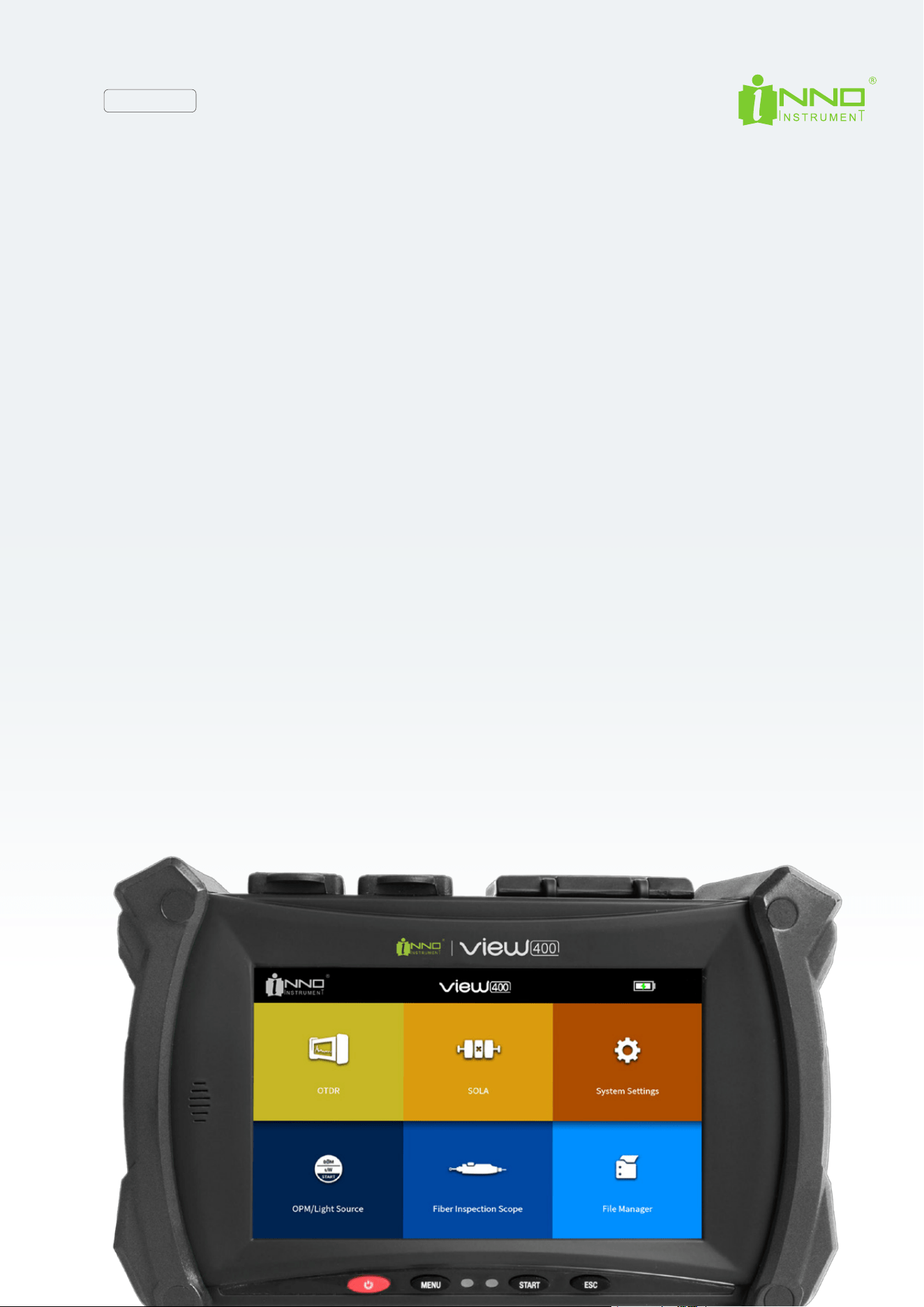
VIEW400
Optical Time Domain Reflectometer
Version: 1.1
User Manual
Please read this manual before starting to use the equipment
Please keep this manual with the equipment

INNO user manual
2
Content
4
6
6
6
7
7
7
7
8
8
8
8
9
10
11
11
13
13
13
13
14
14
15
16
16
16
17
17
18
18
19
19
20
23
23
23
26
26
27
29
Preface
Chapter 1 Overview
1.1 Introduction ...............................................................................................................................................................................
1.2 Basic functions...........................................................................................................................................................................
1.3 Standard conguration..............................................................................................................................................................
1.4 Power supply..............................................................................................................................................................................
1.5 Dimensions and weight ............................................................................................................................................................
1.6 Environmental conditions .........................................................................................................................................................
Chapter 2 Installation
2.1 Safety reminder and precautionary measures.........................................................................................................................
2.2 Safety warnings for operation...................................................................................................................................................
2.3 Transportation and storage.......................................................................................................................................................
2.4 Appearance overview.................................................................................................................................................................
2.5 Charging method........................................................................................................................................................................
2.6 Test port......................................................................................................................................................................................
2.7 Connection testing.....................................................................................................................................................................
Chapter 3 Basic Operation
3.1 Power on/o ..............................................................................................................................................................................
3.2 Adjust the backlight brightness ................................................................................................................................................
3.3 Software upgrad.........................................................................................................................................................................
3.4 File copy......................................................................................................................................................................................
Chapter 4 OTDR Test
4.1 Move waveform key....................................................................................................................................................................
4.2 Move trace key............................................................................................................................................................................
4.3 Partial amplication key............................................................................................................................................................
4.4 “1:1” trace recovery key.............................................................................................................................................................
4.5 Shortcut key for trace amplication.........................................................................................................................................
4.6 Shortcut key for trace shrink.....................................................................................................................................................
4.7 Full screen display key ..............................................................................................................................................................
4.8 Parameter setting key.................................................................................................................................................................
4.9 OTDR key.....................................................................................................................................................................................
4.10 Event key.....................................................................................................................................................................................
4.11 Measurement..............................................................................................................................................................................
4.12 Trace information key................................................................................................................................................................
4.13 Start/stop key.............................................................................................................................................................................
4.14 Save key .....................................................................................................................................................................................
4.15 OTDR setup key ..........................................................................................................................................................................
4.16 Common Setting.........................................................................................................................................................................
4.17 Save le by default.....................................................................................................................................................................
4.18 Run Report key............................................................................................................................................................................

INNO user manual
3
4.19 Save as key...........................................................................................................................................................................
4.20 Next λ key.............................................................................................................................................................................
4.21 Return key............................................................................................................................................................................
4.22 Main menu key (Home).......................................................................................................................................................
Chapter 5 SOLA
5.1 “SOLA” operation..................................................................................................................................................................
5.2 Start/ Stop.............................................................................................................................................................................
5.3 Save/Open.............................................................................................................................................................................
5.4 Management..........................................................................................................................................................................
5.5 Settings..................................................................................................................................................................................
5.6 Run Report............................................................................................................................................................................
5.7 Save as...................................................................................................................................................................................
Chapter 6 File Management
6.1 Overview.................................................................................................................................................................................
6.2 Start le management............................................................................................................................................................
Chapter 7 Light Source
7.1 Overview.................................................................................................................................................................................
7.2 light source operation............................................................................................................................................................
Chapter 8 Fiber Microscope
8.1 Overview.................................................................................................................................................................................
8.2 Start ber end inspection......................................................................................................................................................
8.3 The function of ber microscope..........................................................................................................................................
8.4 Check the preserved image....................................................................................................................................................
Chapter 9 Fiber Microscope
9.1 Overview.................................................................................................................................................................................
9.2 Start le management...........................................................................................................................................................
9.3 File manager function............................................................................................................................................................
9.4 “Operate” Function..................................................................................................................................................................
Chapter 10 System setting
10.1 Overview...............................................................................................................................................................................
10.2 System setting......................................................................................................................................................................
10.3 Functions of system settings.............................................................................................................................................
Chapter 11 System Informatio
11.1 System information..............................................................................................................................................................
Attachment
Term list
30
30
30
31
32
32
33
33
35
37
37
38
39
39
40
40
40
41
41
41
41
43
44
44
44
45
44
48
48
48
48
45
45
52
55
INNO user manual
4
SafetySymbols
SafetySignsusedintheManual
SafetySignsusedintheManualandMachine:
Inordertopreventpersonalinjuryandlossduetothemisoperationoftheinstrument,INNO Instrumentusesthefollowing
safetysignstoindicaterelevantsafetyinformation.Beforeusingtheinstrument,besuretoclearlyunderstandthemeaning
ofthesesigns.
Someorallofthesignsmaynotbefoundontheinstrument.Inaddition,safetysignsofthedevicemaynotbemarkedin
theillustrationsofthismanual.
Thefollowingsafetysignsaremarkedinthedevice,neartheoperationposition,orinthemanualtoproviderelevantsafety
informationandprompttheusertooperatewithcare.Beforeusingtheinstrument,besurethatyouhaveclearlyunderstood
themeaningofthesesignsandtakenecessaryprecautionarymeasures.
Preface
Sign Description
Dangerous
Thissignindicatesthatthisisaverydangerousoperation,andimproperoperationwillleadtoserious
injuryandevendeath.
Warning
Thissignindicatesthatthisisarelativelydangerousoperation,andimproperoperationwillleadto
seriousinjuryandevendeath.
Caution
Thissignindicatesthatthisisarelativelydangerousoperation,orhasacertainharmandimproper
operationduetocarelessnesswillleadtomildorseriousinjuryandloss.
Sign Description
Thissignindicatesaforbiddenoperation.Thiscirclewithaslashislabeledontheoperationposition
ornearit.
Thissignmeansthatyoumustbecarefulwhenperformingacertainoperation.Thiscirclesignis
labeledontheoperationpositionornearit.
Thissignindicatesawarningandcaution.Relevantcontentappearsinsidethetriangleornearit.
Thissignindicatesanexplanation.Relevantcontentislistedinthebox
Thesesignsindicatethatthelabeledcomponentsshouldberecycled.
INNO user manual
5
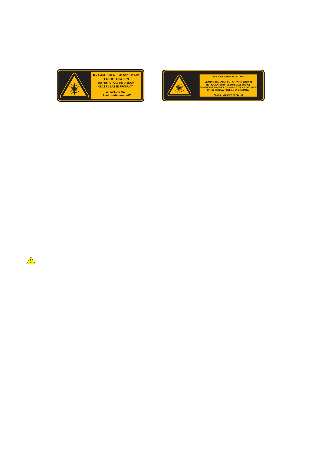
LaserSafetyLabels
ElectricalSafety
Precautions
Caution
Inordertoreducedamagetoinstrumentandinjuryevendeathofhumanbody,thefollowingwarningsaregiven:
• Donotuseiftheinstrumentortheexternalchargerwasdamagedorruptured
• Onlytheexternalpoweradapterprovidedbyourcompanycanbeused.Forotherexternalpoweradapters,wecannot
guaranteetheirperformanceandsafety
• Donotusethepoweradapteroutdoorsorinhumidplaces
• esurethattheexternalinputvoltageiswithintheallowablerange
Replace internal memory battery:Thisinstrumentusesalithiumbatteryasthepowersupply.Ifitexceedsthemaximum
servicelifeandneedstobereplaced,pleasecontactspecializedpersonnelforreplacement.
External memory: ThisdeviceusesUSBasexternalmemorytosavedata
INNOInstrument(China)Inc.isnotresponsiblefordataloss
INNO user manual
6
1.1 Introduction
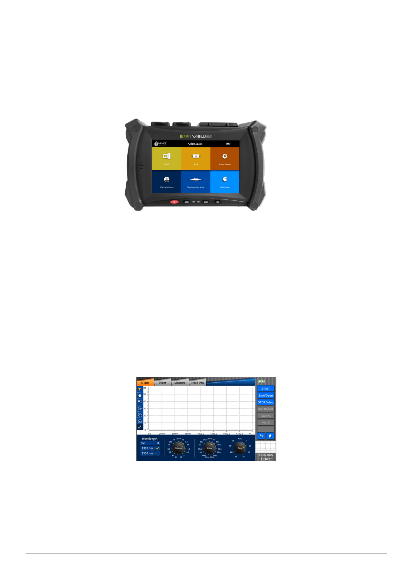
High-performance hardware and wieldy software used in VIEW400 can shorten the process of installation, debugging and ber
distance maintenance. This chapter will describe the features and basic operations of VIEW400 OTDR test unit.
1.2 Basic function
View400 is mainly used for fiber fault diagnosis, especially in FTTH application. Besides the basic OTDR function, optical
power meter and light source function for ber discriminating are also internally installed.In addition.
OTDR Test
Based on Rayleigh scattering and Fresnel Reection principle, OTDR can realize the relevant measurement on optical ber link.
It can also carry out distance measurement to ber connection loss and fault location, thus it can determine the any point loss
on the optical ber. OTDR auto analysis function can automatically analyze measured traces to nd the events on ber, such as
the reection loss or the splicing point over loss threshold limit. Besides, the detected data can be also displayed in the event
table on OTDR.
OPM/LS module
The optical power meter is used to measure absolute optical power meter or relative optical power loss through a span of
optical ber. This module can measure optical power of multi-wavelength.
Chapter 1 Overview
INNO user manual
7
LS (Stable light source)
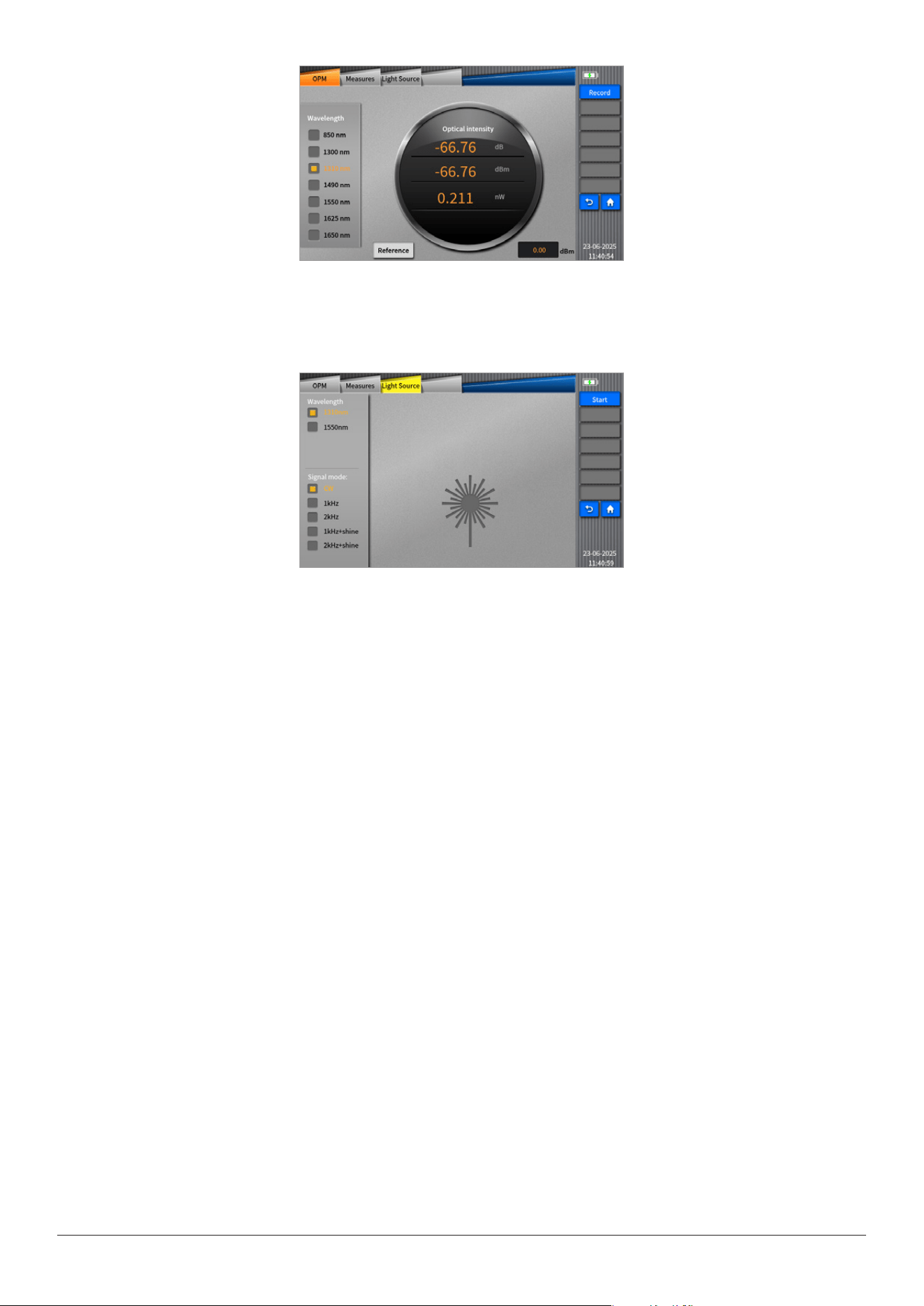
Light source with dierent wavelengths (i.e. 1310/1550nm) and multiple signal modulation modes in-built in View400 are able
to satisfy demands in actual applications, as shown in the following picture.
Fiber microscope (Fiber Inspection Probe) module
The grind quality and cleanliness of optical connector can be detected by being connected external ber inspection device to
USB port.
1.3 Standard Conguration
• Capacitive touch 5inch,800×480,color LCD
• AC adapter/charger, power cord
• Rechargeable lithium battery pack
• Basic menu operation
• Operation Manual
• Protective Case(Primarilyusedfortransportationandstorage,notforcarryingduringoperation.)
1.4 Power supply
• AC/DC adapt:Input:100V~240V,50/60Hz,1.5A
• Input:19V,3.42A,lithium battery:7.4V,4300mAh
1.5 Dimensions and weight
• Size: 172mm×111mm×64mm
• Weight: ≤795g
1.6 Environmental conditions
• Operating environment: Temperature: --10℃~+50℃
• Storage environment: Temperature: -40℃~+70℃

INNO user manual
8
Chapter 2 Installation
Usage Category and Installation:
This device is classied as a Mobile Device according to FCC radiation exposure regulations. It is designed to be operated
on a stable horizontal surface (such as a desk or a specialized workbench) or xed on a tripod.
It is NOT intended for handheld use or to be worn on the body during operation.
2.1 Safety reminder and precautionary measures
It is very important to keep in mind that VIEW400 is designed for ber testing, not for any other purpose. OTDR is a high precision
instrument and should be carried with great care. Therefore, please always observe the following safety rules and general
specications when using and carrying the VIEW400. Failure to take these safety measures or to comply with the warnings
and precautions described elsewhere in this manual will violate the safety standards for the design, manufacturing and use of
OTDR. Consequences due to violations of these requirements will be assumed by users!
2.2 Safety warnings for operation
① Do not operate the OTDR in a ammable or explosive environment.
② Do not disassemble or assemble any component of the OTDR without authorization except for the components stated
in this manual that are allowed to be replaced by the user. Component replacement and internal adjustment can only
be performed by authorized maintenance personnel.
③ Be careful when connecting the battery charging adapter cable. Do not pull the cable when removing it from the socket,
but hold the plug. Be sure that the cable is in good condition to avoid the risk of re or electric shock.
④ Do not expose the OTDR to re, electric shock, rain, or humid environment.
⑤ When the OTDR encounters the following situations, please turn it o immediately and pull the adapter out of the
power input port of OTDR. Otherwise, it may lead to serious consequences, such as the abnormal function of the OTDR
or damage beyond repair.
★ Fumes, peculiar smell, or abnormal sound.
★ Liquid or foreign matters enter inside the OTDR.
★ OTDR suers from strong vibration or impact.
Please contact the maintenance center immediately in case of the above faults. If the OTDR is in a fault state without
taking timely measures, it may lead to device scrap, electric shock and re, as well as personal injury (even death).
⑥ Please use the exclusive VIEW400 AC adapter only. Inappropriate AC power supply may lead to fumes, electric shock and
device damage, and even re, personal injury or even death.
⑦ Please use the exclusive AC power cord only. Do not place heavy objects on the power cord, and do not heat the power
cord or change the power cord. An inappropriate or damaged power cord may lead to fumes, electric shock and device
damage, and even re, personal injury or even death.
2.3 Transportation and storage
① When the OTDR is transported to a warm environment from a cold environment, try to adopt the gradual heating mode,
otherwise condensation will be produced inside the instrument, leading to adverse eects on the instrument.
② Please pack the device properly when OTDR is not in use.
③ Keep the OTDR clean and dry.
④ The OTDR has been precisely calibrated and adjusted. The instrument should be transported in its original case to prevent
damage.
⑤ Please avoid direct sunlight or overheated environment.
⑥ Keep the minimum humidity when stored. Relative humidity should be less than 95%.
INNO user manual
9
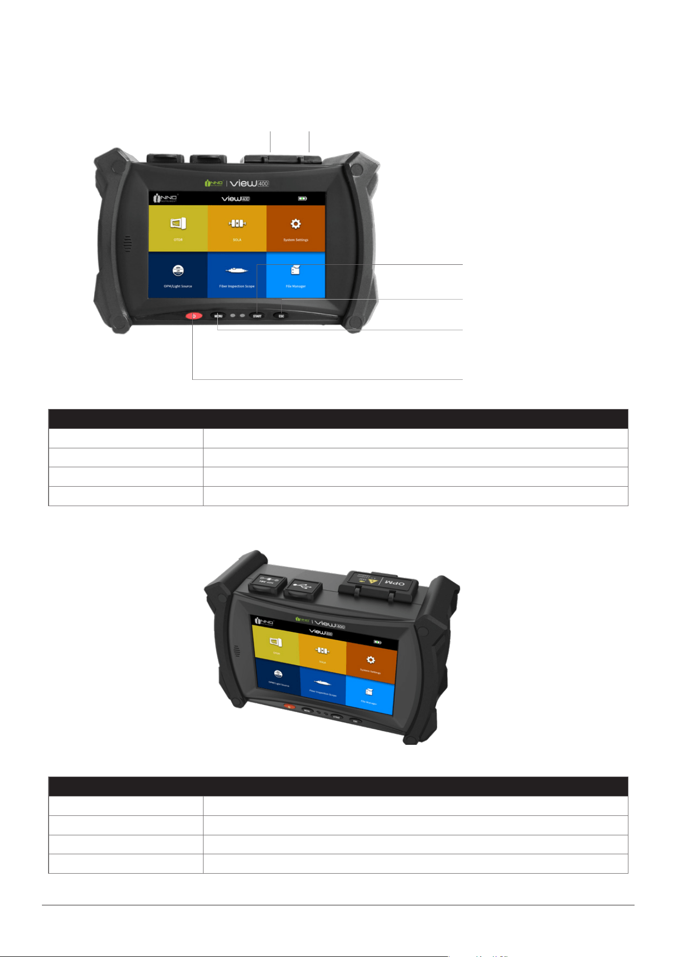
2.4 Appearance overview
Description of keys
Power Switch(on/off)
MENU Backtomainmenuinterface
START Start/Stopmeasuring
ESC Backtopreviousmenu
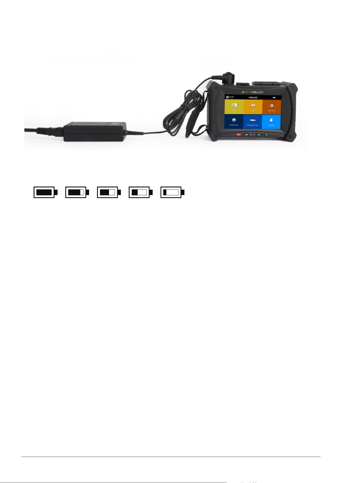
Port description
DCpowerconnector Connecttheadapter.
SMFport VIEW400testinginterface,appliedinOTDRandlightsourcemodulesofVIEW400.
OPMport Opticalpowermeterport.
USBport ConnectUSBstoragedevicewithberendprobe.
Front Panel
OpticalConnector OpticalPowerMeterPort
On/Okey
Measurementkey
Begin/Stopmeasuring
Menukey
(Pressitwillreturntothe
mainmenuinterface.)
Escape key
(Return to previous menu)
The upper connect panel
INNO user manual
10
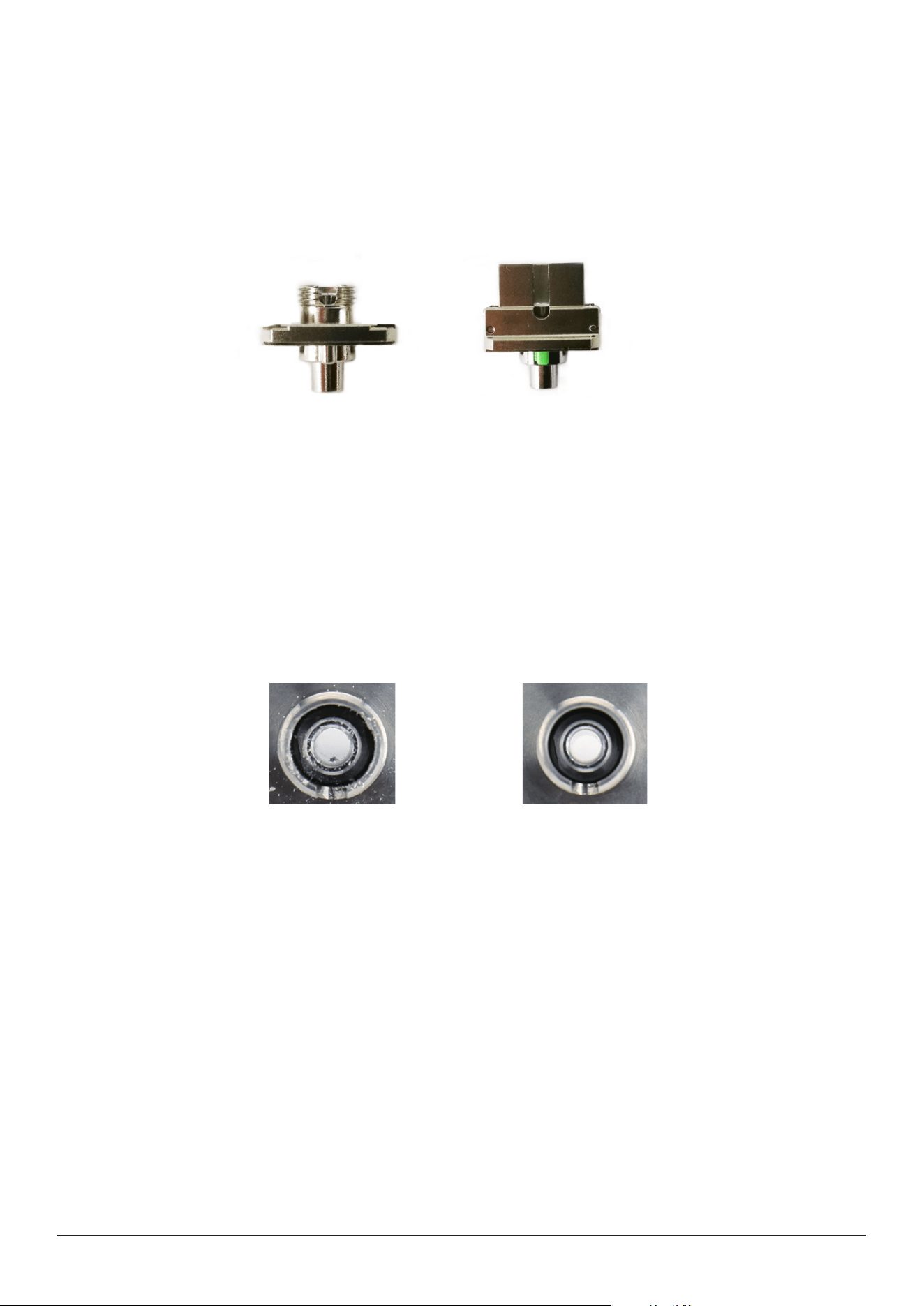
2.5 Charging method
Remaining battery capacity can be checked according to the battery status when VIEW400 is powered on.
INNO user manual
11
2.6 Test port
The measurement port of VIEW400 is located on the upper panel of the host. There will be 1 or 2 measurement ports
depending on the type of VIEW400. The measurement port connected to optical ber depends on the testing application
and measured wavelength. The following are mixed universal connectors FC/SC used in VIEW400:
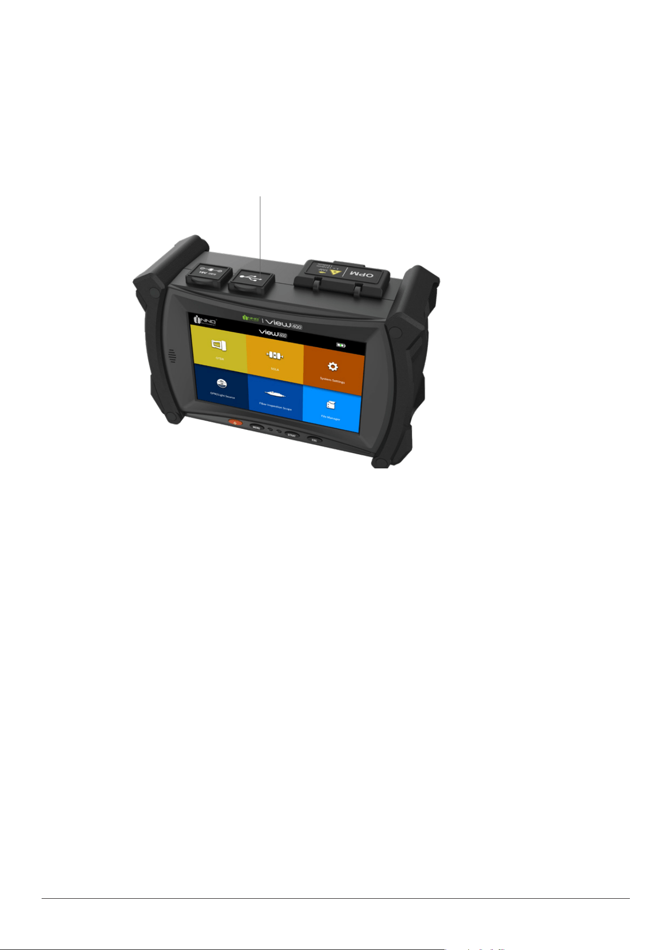
FCSC
Steps for cleaning the universal connectors are as follows:
1. Open the cover of the measurement port which needs to be cleaned
2. Take down the universal connector
3. Blow compressed air toward the top of connecting bar
4. Use a special cleaning belt or dust-free belt dipped in alcohol to clean the top of connecting bar
5. Use compressed air to blow-dry the top of connecting bar
6. Options: turn o VIEW400, and observe the top of connecting bar by microscope or magnifying lens
Topofthecontaminatedconnectingbar Topofthecleanedconnectingbar
2.7 Connection testing
Connect the test ber
Measurement port is used to connect the tested ber of OTDR/OPM/LS application.
Steps for connecting the tested ber to the measurement port:
1. Clean the ber jumper and connect it to the measurement port.
2. Clean the ber to be tested
3. Connect the ber jumper with the tested ber.
INNO user manual
12
Connectberinspectionprobe(bermicroscope)
ConnectwithexternalberendinspectionprobefromUSBinterface.Followsaretheprocesstoconnectthevisuallightsource:
•OpenthecoverofUSBport.
•Connectberjumperintotheconnectorofmicroscope.
USB port cover
INNO user manual
13
Chapter 3 Basic Operation
3.1 Power on/o
Power on:
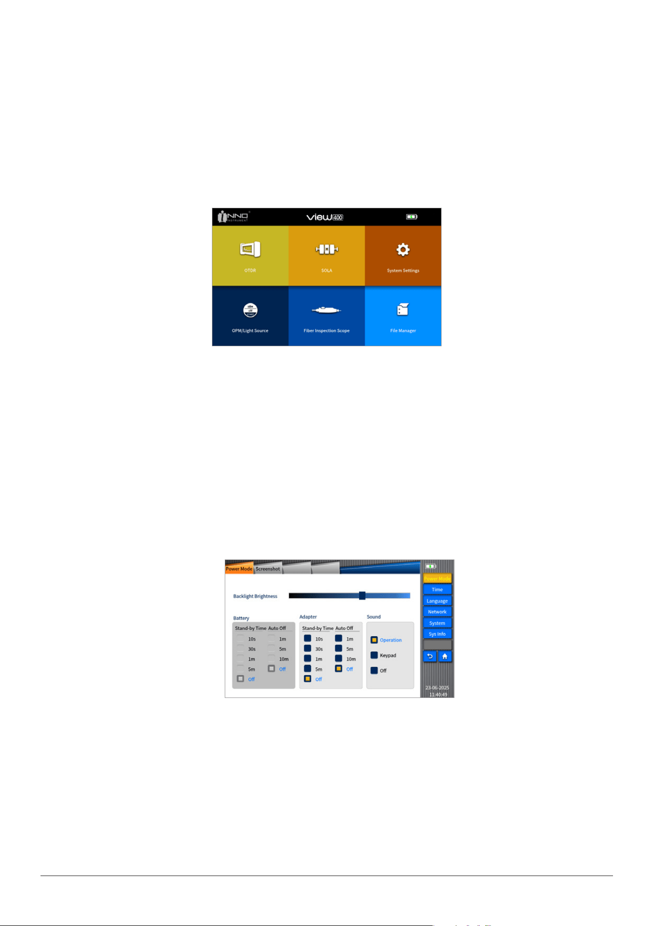
Press the power key, the name of the device will appear on VIEW400 screen, and then the boot screen of INNO Instrument will
appear. Later the following main menu screen will appear.
3.2 Adjust the backlight brightness
Click the icon of backlight brightness to switch the backlight brightness. Dierent color icons represent dierent levels of the
brightness. VIEW400 series supports eight levels of brightness switching.
3.3 Software upgrade
Please refer to Section 10.3.5 for detailed information.
Power o:
Press and hold the power key until the screen of shutdown appears (grey logo).
Note: Under any circumstance can you press and hold the power key more than ten seconds to force shutdown.
INNO user manual
14
Chapter 4 OTDR Module
3.4 File copy
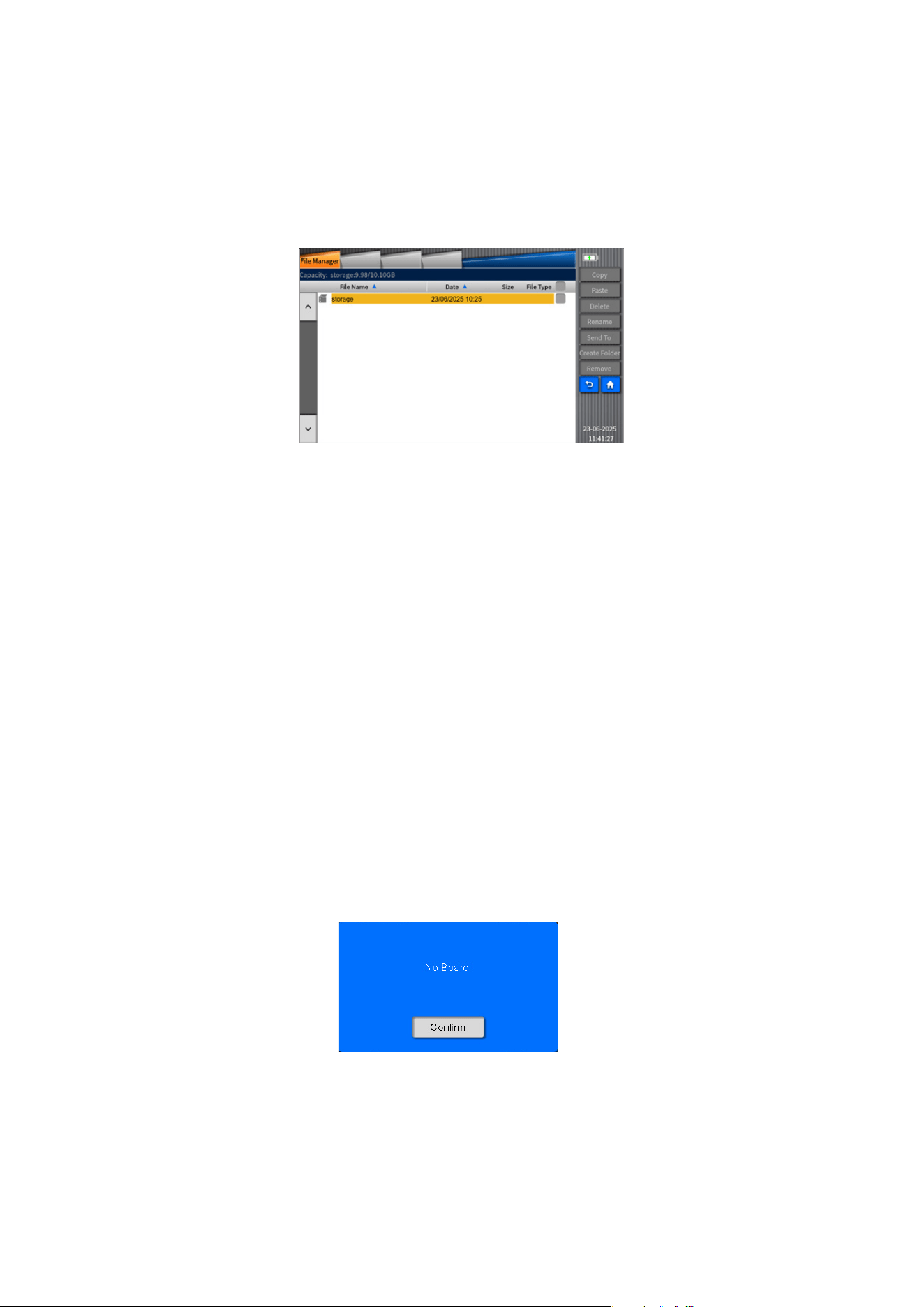
As shown in the following gure, plug in the external storage device, view the path of the external storage device in "le
management", and then execute operations of "copy", "paste", "delete", "rename", "send to USB", "new folder", "remove
device" for the le;
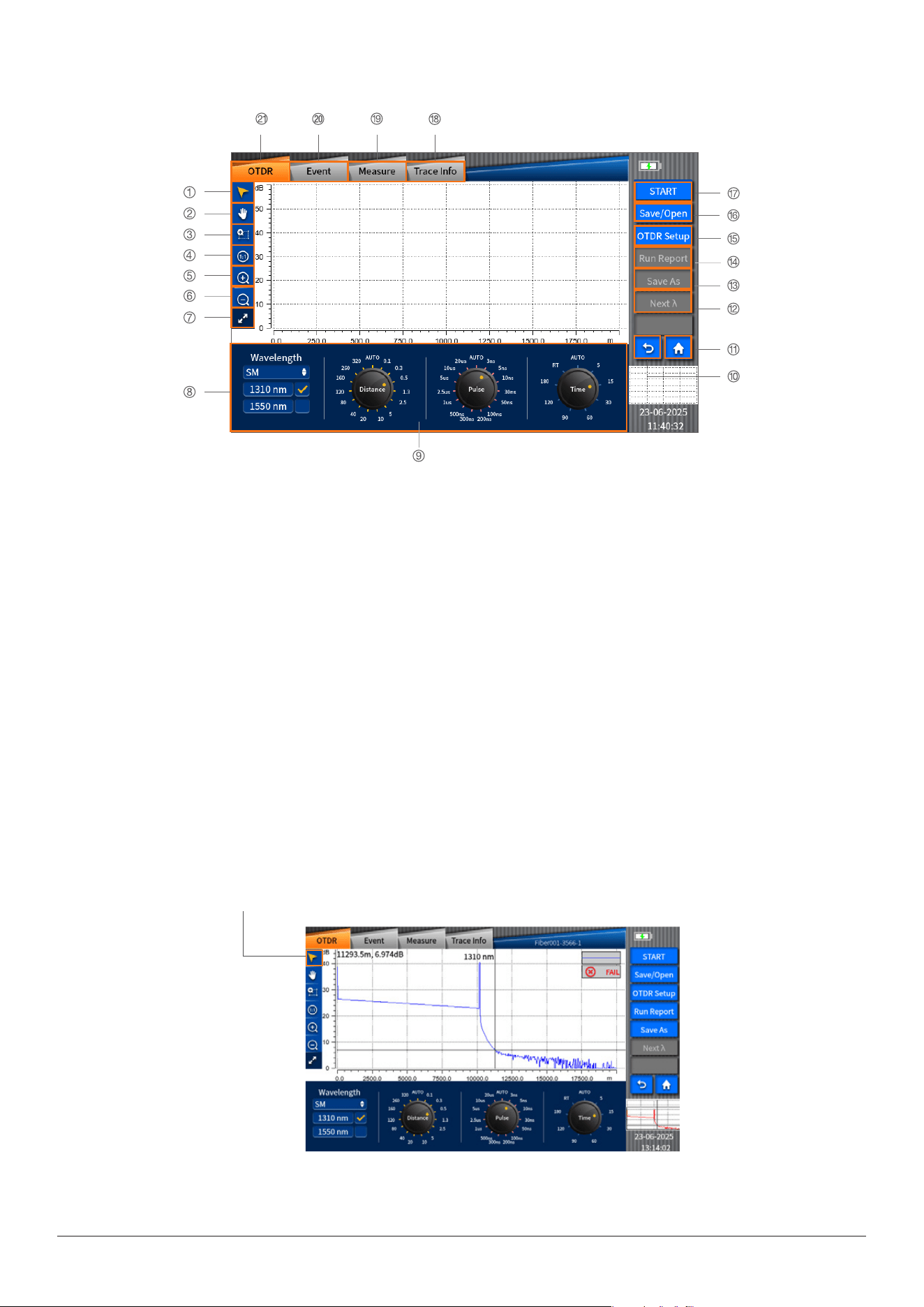
Themodulesusedinthisdeviceareinterchangeableasneeded.TheOTDRmoduleshouldbeloadedatrstbeforeOTDR
functionisenabled.Ifnot,apop-upmessagewillappearonthescreen,asshowninthefollowingpicture:
INNO user manual
15
12. Nextλ key
13. Save as key
14. Create report key
15. OTDR setting key
16. Save/Open key
17. Start/stop key
18. Trace information key
19. Measurement key
20. Event key
21. OTDR key
1.Movecursorkey
2.Movetracekey
3.Partialamplicationkey
4.“1:1”tracerecoverykey
5.ShortcutkeyforTraceamplication
6.ShortcutkeyforTraceshrink
7.Fullscreendisplaykey
8.Boxesforselectingwavelength
9.Parametersettingkey
10.Returnkey
11. Home key
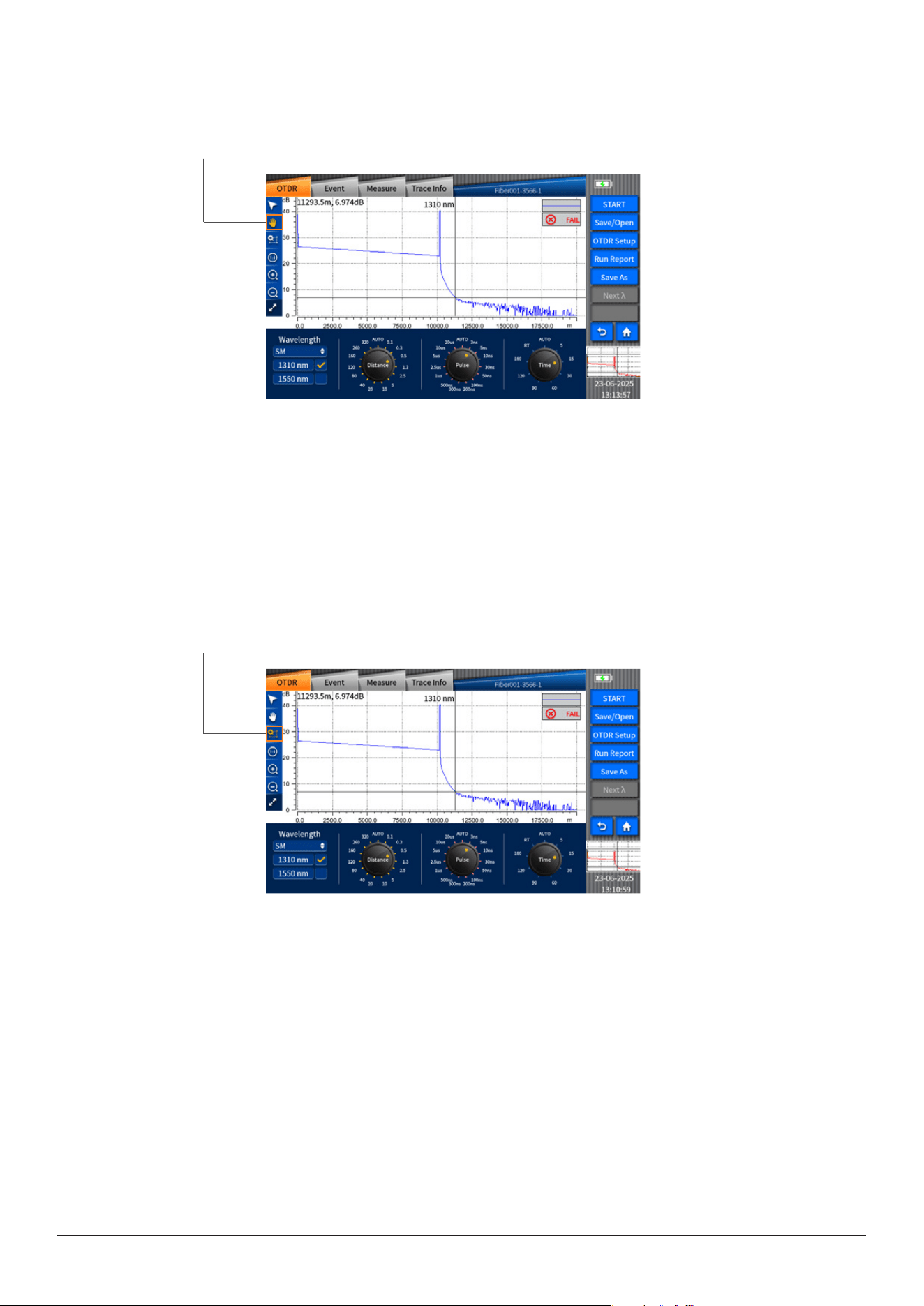
Movecursorkey
4.1 Move cursor key
After Clicking the Move cursor key, you can change the position of the cursor on the screen by touching on the trace.
INNO user manual
16
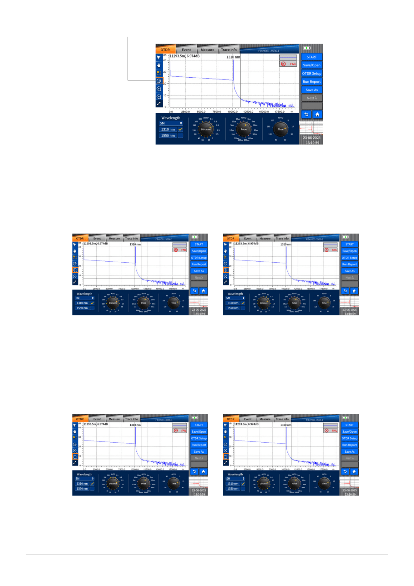
4.3Partialamplicationkey
Click“partialamplication”keyandthenclickthescreentoselecttheareaoftracedisplayed.Thisareawillbeampliedand
displayedon“tracedisplaysmallscreeninterface”.
4.4“1:1”tracerecoverykey
Asshowninthefollowingpicture,afterzoominginoroutthetrace,click“1:1”tracerecoverykeytoresetthetrace.
4.2Movetracekey
Clickthekeyfortracemoving;youcanmovetheampliedtracebytouchingonthescreen.
Movecursorkey
Partialamplicationkey
INNO user manual
17
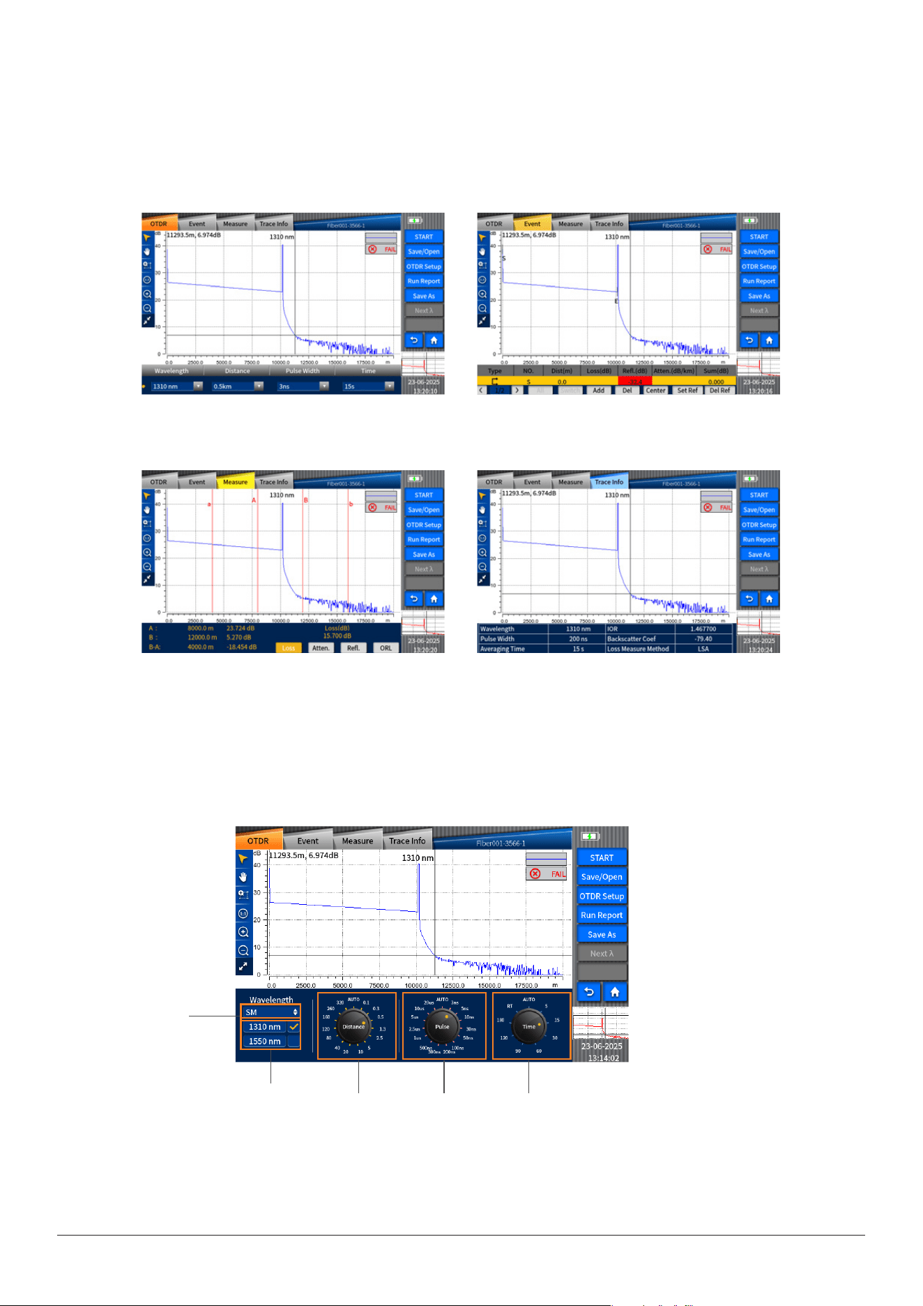
4.5Shortcutkeyfortraceamplication
Clickthe“Movecursor”keyor“Movetrace”keyandthenclickthe“Traceamplication”shortcutkeytozoominthetracehori-
zontally.(Picture1)Clickthe“Partialamplication”keyandthenclickthe“Traceamplication”shortcutkeytozoominthetrace
vertically.(Picture2)
4.6Shortcutkeyfortraceshrink
Clickthe“Movecursor”keyor“Movetrace”keyandthenclickthe“Traceshrink”shortcutkeytozoomoutthetracehorizontally.
(Picture1)Clickthe“Partialampli-cation”keyandthenclickthe“Traceshrink”shortcutkeytozoomoutthetracevertically.
(Picture2)
“1:1”tracerecovery
Picture1
Picture1
Picture2
Picture2
INNO user manual
18
4.7 Full screen display key
Clickthe“Fullscreendisplay”keytodisplaythetraceinfullscreen,wheretheOTDR,event,measurement,andtraceinfor-
mationareshown.Clickthiskeyagaintorevertthescreentothepreviousone.
Fibermode
selection
4.8 Parameter setting key
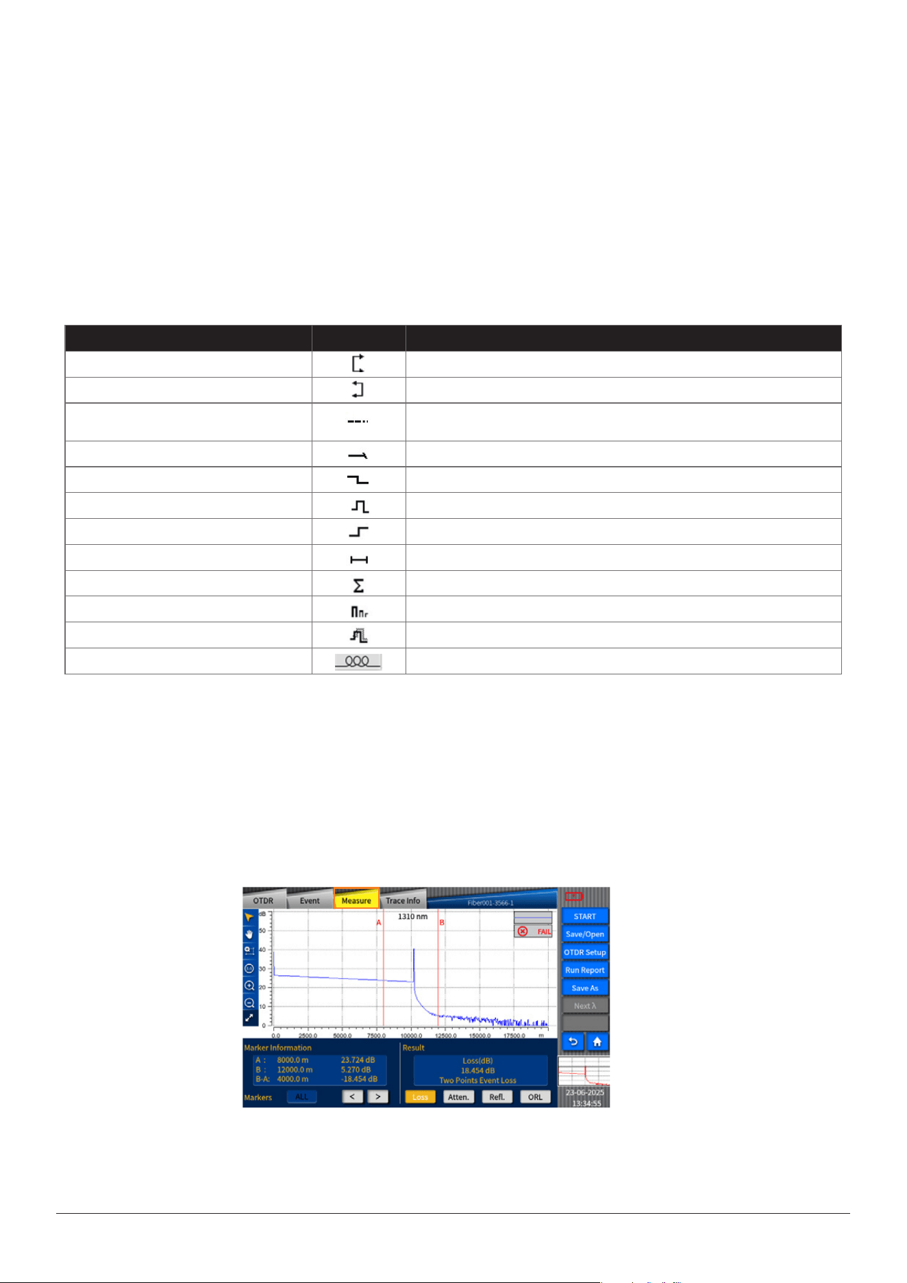
Thewavelength,distancerange,pulsewidthandaveragetimecanbesetontheinterfaceofmeasurementparametersetting.
TheOTDRmenuisshownasfollows:
TheMeasurementmenuisshownasfollows:
TheEventmenuisshownasfollows:
TheMeasurementmenuisshownasfollows:
Wavelength
selection
Range
setting
Pulsewidth
setting
Time
setting

INNO user manual
19
In the “event” menu, there are some functions in it, such as “move the event point”, “change the event point”, “add”,
“delete”, “maximize”, “set Ref”, “delete Ref” and so on.
1)The function of moving the event point is to move the mark line to a certain event point.
2)The purpose of changing the event point is to view the specied measured data in detail by taping the arrow keys left or
right.
4.9 OTDR key
Asshowninthepicture,click“OTDR”toenterintoOTDRmeasurementsettinginterface.
4.10 Event key
Asshowninthepicture,enterintotheeventinterfacebyclicking“Event”key.TheinformationofeventssuchasType,Number,
Location,Loss,Reectance,Attenuationandcumulativeloss(Sum)canbeshown.
PleaserefertoSection4.11.1for“Loss”.PleaserefertoSection4.11.3for“Reectance”.PleaserefertoSection4.11.2for“Attenua-
tion”.
CumulativeLoss(Sum):ItreferstothetotallossfromportofOTDRtoacertainpoint.
Eventloss+berspanloss=cumulativeloss
INNO user manual
20
Event type Event icon Brief description
Startpointofcrosssegment Startpointofber(generallythersteventpoint)
Endpointofcrosssegment Endpointofber(generallythelasteventpoint)
Continuousber
Itindicatesthatnoberendisfoundatthesamplingend,andthesampling
pointsareinsucient
Endofanalysis Impulselightintensityisinadequate,sotheanalysisstopshalfway
Non-reectionevent Eventssuchas"loss"
Reectionevent Reectionevent
Gainevent Gainphenomenonappears,generallyregardedaspseudogain
Fiberspan Fiberspanwithoutanyevent
Combinationofreectionevents Multiplereectioneventsappeartogether
Echo Echophenomenonappears
Reectionevent(possibleecho) Possibleechophenomenon
Macrobendingevent Attenuationduetoberbending
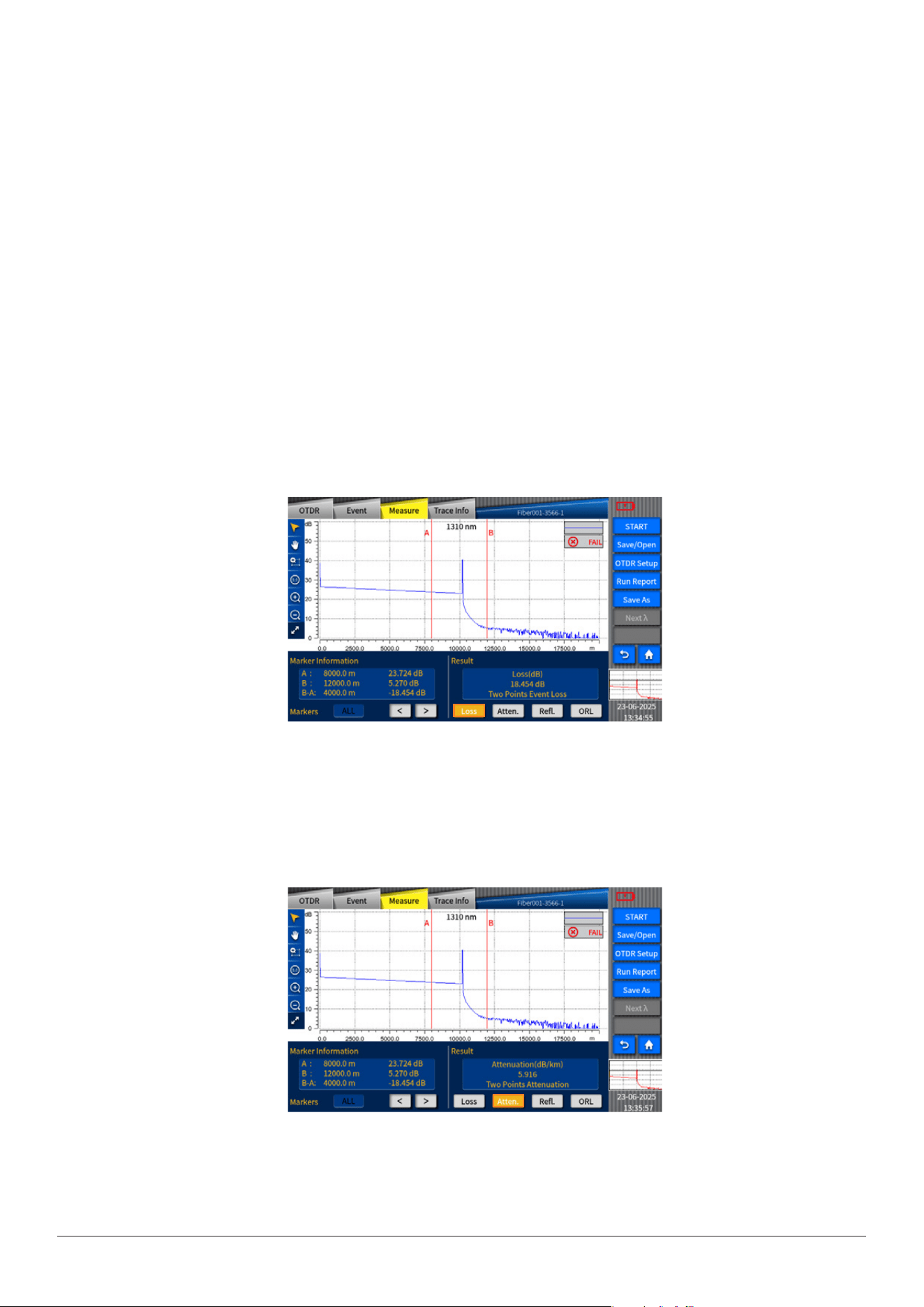
Note:Types of events are shown in the following table.
4.11 Measurement
As shown in the gure, enter the measurement interface by clicking the "Measurement" key.
3)“Add” is used to insert event point in the selected position on the trace.
4)“Delete” is used to delete the inserted event point.
5)“Maximize” is used to amplify the event trace.
6)“Set Ref” is used to reset a starting point. All the data will be measured through the new set point. (“Reference starting point”
can only be set between original point and event point. If there is no event point after original point, the starting point can’t
be set.)
7)“Delete Ref” is used to delete the starting point that had been set.
INNO user manual
21
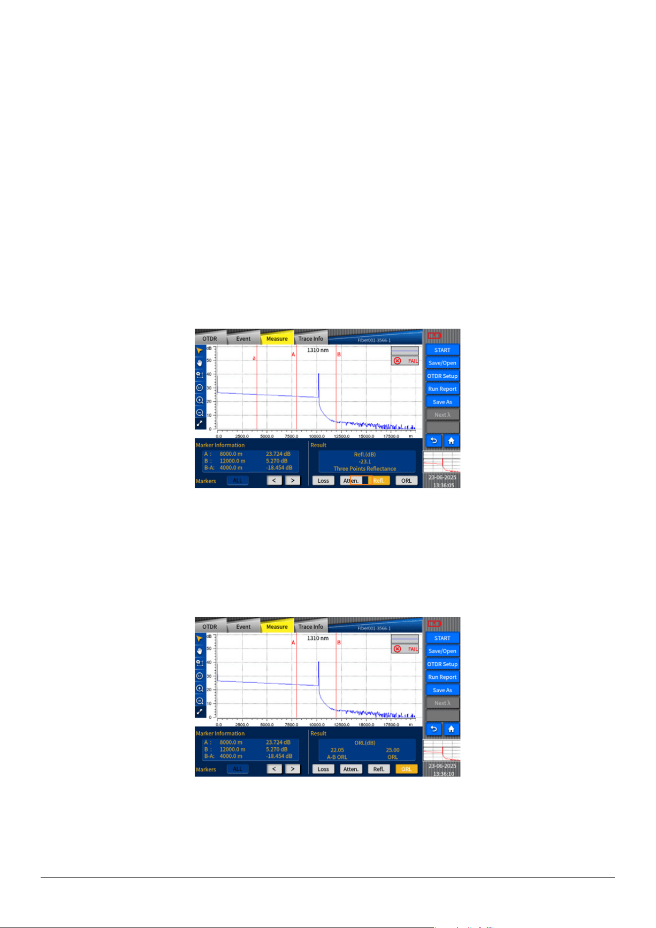
In the measurement interface, click on the letter to switch “Mark line”, which can be moved by pressing on “<”、“>”keys or
touching manually. The loss and loca- tion of the Mark line will be displayed under the “Mark Line Information”, while the loss,
attenuation, reectance and ORL (Optical return loss) will be displayed under the “Result”.
Loss
Event loss (expressed in dB) is calculated by measuring the reduced signal strength in Rayleigh backscattering (RBS) caused by
this event. Both reection and non-reection events can cause event loss.
VIEW400 provides two loss calculation methods
1. Four-point event loss "LSA": The event loss is calculated by the least square approximation (LSA) method. The losses
shown in the event list are measured using the four-point method. Set four points as "a", "A", "B" and "b". The area
between "a" and "A" and the area between "b" and "B" are tted with two straight lines, so that the event loss can be
obtained according to the intercept between the two lines;
2. Two-point method for loss calculation "TPA": The loss between the two marker lines can be obtained by subtracting the
Y-coordinates between the two marker lines.
3. The selected item in the marker line frame is the currently selected marker line and can be moved. The marker line
information is updated synchronously while moving.
Attenuation
Click “Measurement” key and then select “Attenuation” key.
INNO user manual
22
Optical return loss (ORL)
ORL calculation:
1)ORL between marker line A and marker line B.
Total ORL between start point of ber span and the end point of ber span.
Reectivity
Reectance refers to the ratio between reected light and incident light.
3- Point method for reectance: 3 points refer to the points on the marker line a, marker line A and marker line B. The trace
should be zoomed in and the marker line A should be located within the range of linearity before event to be tested; the
marker line a should be located prior to the range of linearity before event to be tested; the marker line B should be located at
the peak of wave of reective event to be tested. All the reectance of reective events at the fault points on the ber can be
measured and merged.
(Note: in real-time mode, the value of the reectance may not be always ac- curate.)
The attenuation measured in two points refers to the RBS attenuation given by the distance function between 2 points (as per
the ber standard, it is labeled as dB/km). Only use these 2 points to calculate but there is no need to gain average value.
LSA: the attenuation between 2 points (distance loss) can be measured according to the backscattering data between the
marker line A and marker line B by linear tting. The LSA attenuation corresponds to the dierence of power (dB) between 2
points on the ber.
Compared with TPA (Two-point analysis method), the average measurement value can be gained by LSA. The higher the noise
level is, the more reliable the LSA will be. But when events such as ORL happen between two marker lines, LSA should not be
adopted.
(Only the ORL of the single mode ber can be calculated. In real-time mode, the value of the ORL may not be always accurate.)
INNO user manual
23
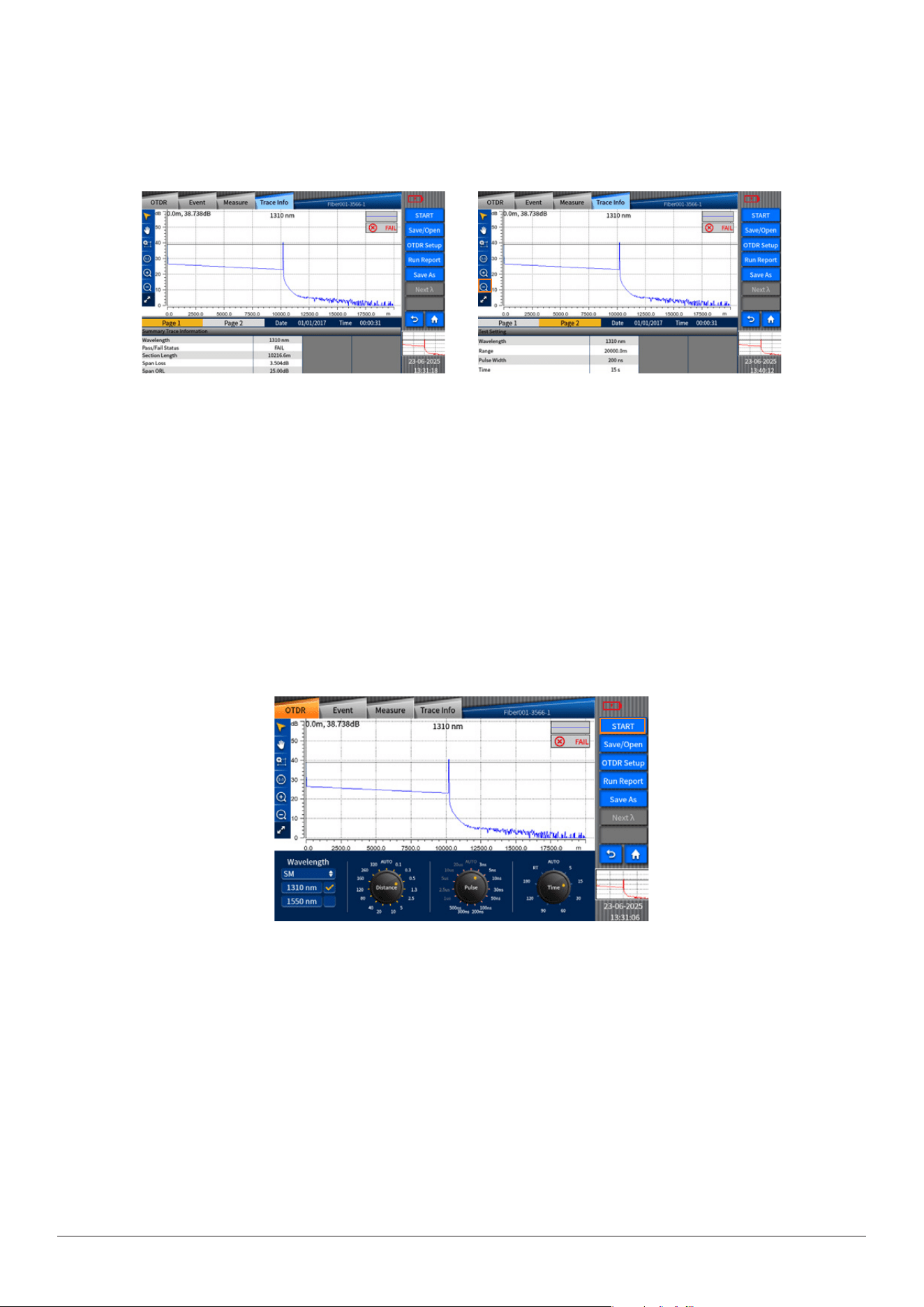
4.12 Trace information key
As shown in the following pictures, enter the trace information interface by clicking “Trace info”. On page one display the
measured data at a wavelength, while on page two display the measurement parameter setup at a wavelength.
4.13 Start/Stop key
As shown in the picture, click “Start” key to begin measuring and click “Stop” to stop measuring.
4.14 Save/Open key
On “Save/open” interface, you can carry out the operation of loading/reading, saving, or clearing the measured trace.
The interface of trace information will show basic information about the measured trace, such as :
le name, date, wavelength, pulse width, average time, refractive index, and backscattering and loss measurement method.
Picture1 Picture2
INNO user manual
24
Save the le
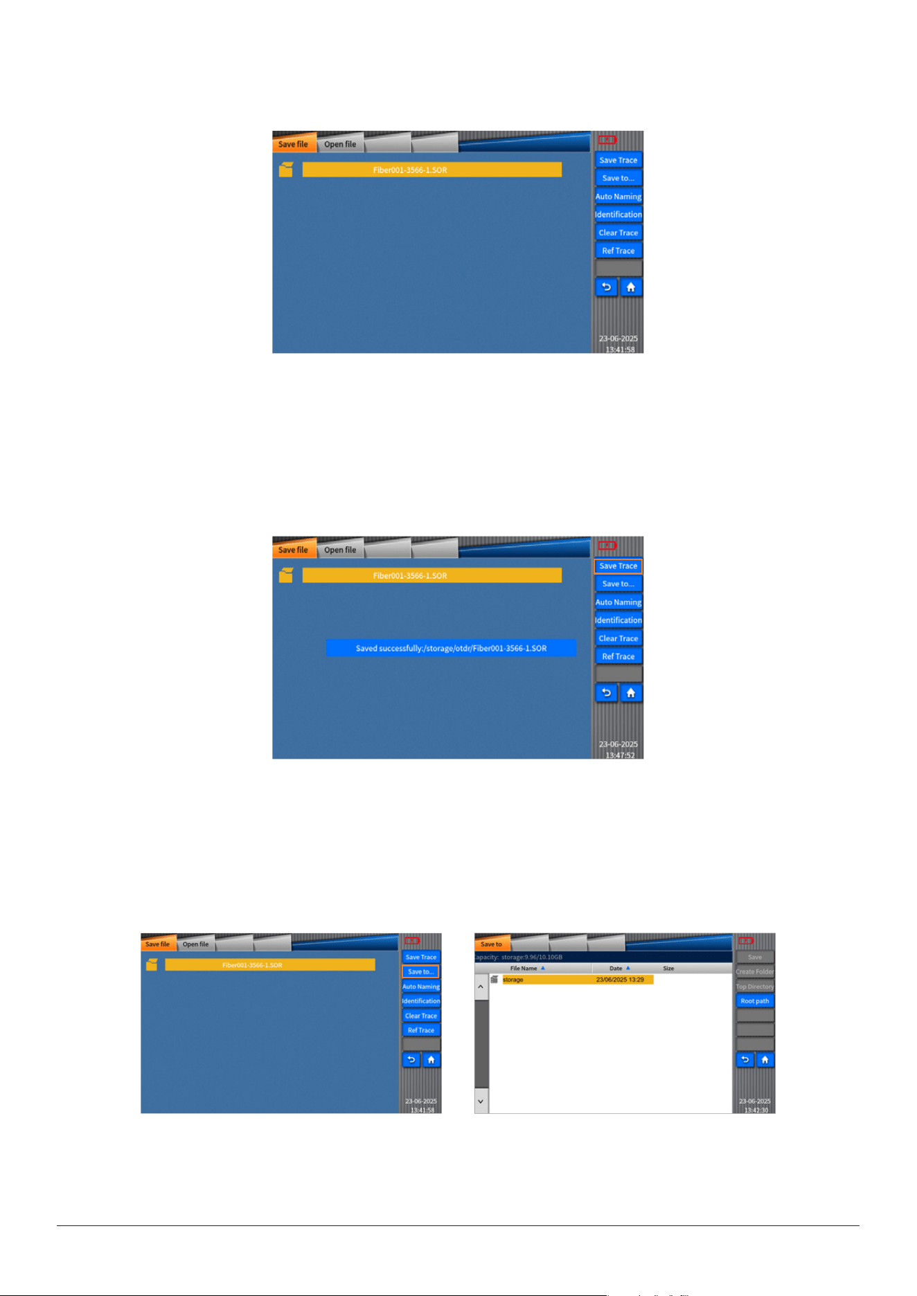
As shown in the gure, enter the "Save le" interface by clicking the "Save le" key.
Therearefunctionssuchas“Savetrace”,“Saveto”“Autonaming”“Identication”and“Cleartrace”inthe“Savele”menu.
Savetrace
Asthefollowingpictureshows,theselectedtracecanbesavedif“Savetrace”iconisclicked.
Saveto
Youcanclick“Saveto”keytoopenthemenuwithsaveddirectories,fromwhichyoucanselectonetosavethele.
Picture1 Picture2
INNO user manual
25
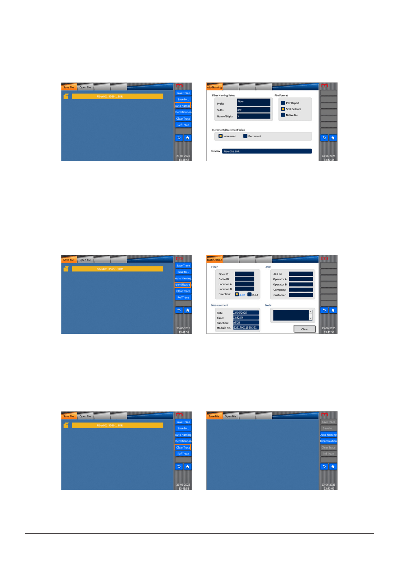
Autonaming
Enterthe“Autonaming”menufromthe“Savele”menuafterselecting“Autonaming”key.Andthenyoucansetthelename,
leformatandthemodesofsortingles.
Identication
Enterthe“Identication”menufromthe“Savele”menuafterselecting“Identication”key.Andthenyoucansettheitems
suchasberID,taskIDandmeasurementID.
Cleartrace
Asshowninthefollowingpictures,thetracecanbeclearedif“Cleartrace”iconisclicked.
Picture1
Picture1
Picture1
Picture2
Picture2
Picture2
INNO user manual
26
Openle
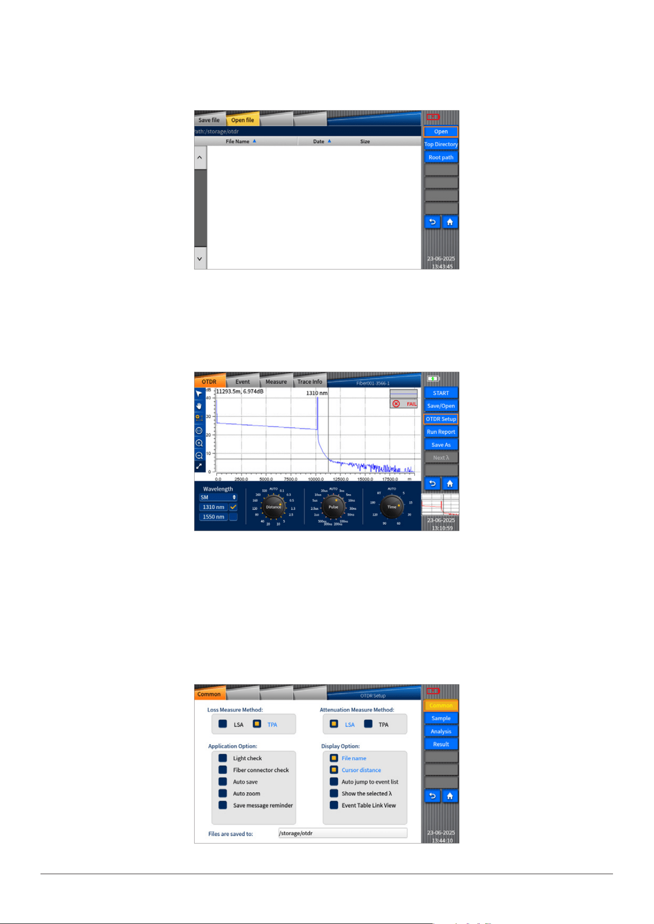
Asshowninthepicture,click“openle”,selecttheleandthenclick“Open”toopenthele.
4.15 OTDR setting key
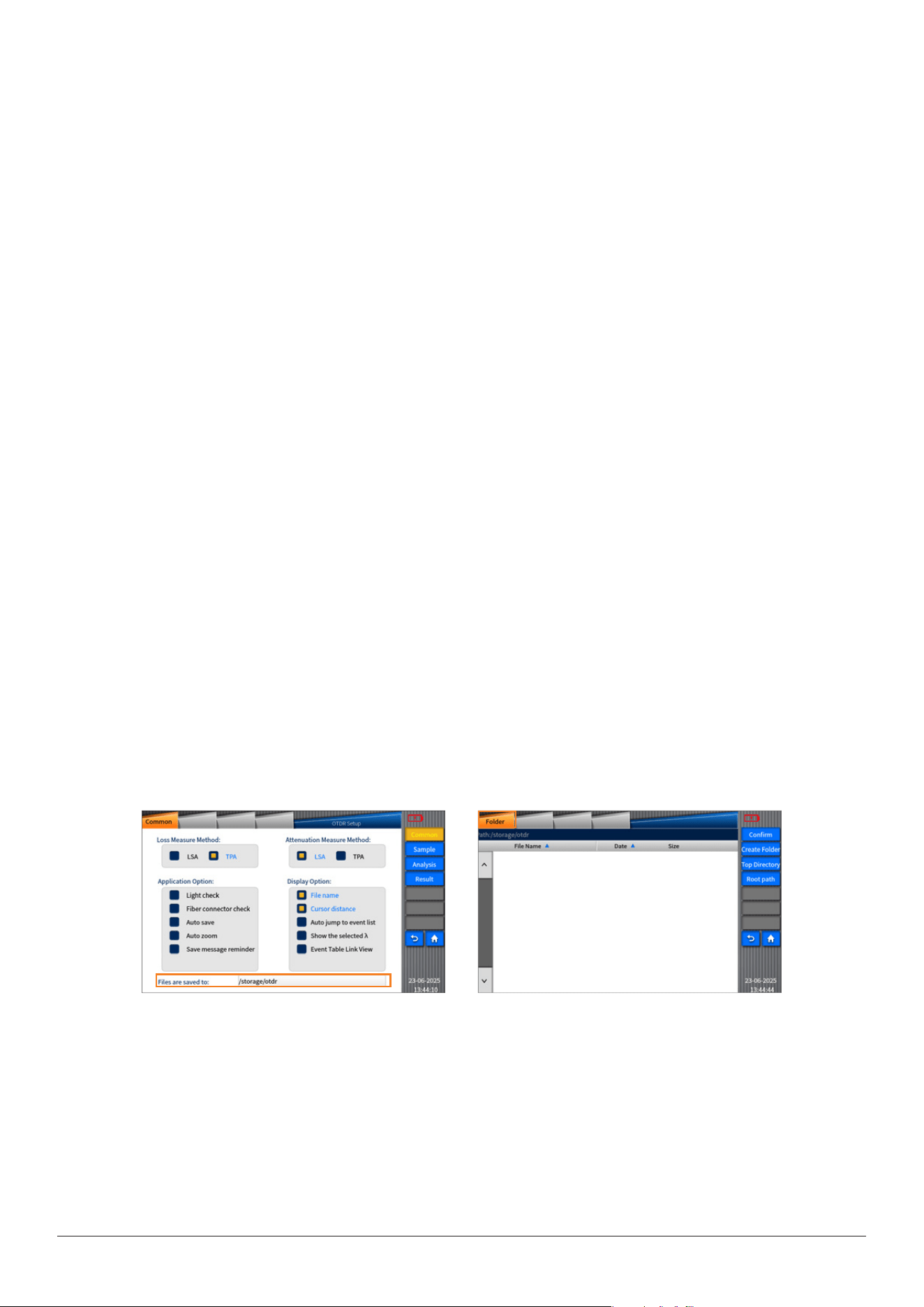
As shown in the picture, click “OTDR set “key to enter into OTDR setup interface.
Thereare“commonsetting”,“samplesetting”and“analysissetting”“thresholdsetting”and“customsetting”optionsinOTDR
settings.
4.16CommonSetting
“Common”isusedtoset“lossmeasuremethod”,“attenuationmeasuremethod”,“applicationoption”,“displayoption”and
“Pathoftheletobesaved”.Pleaserefertothefollowingpicture.
INNO user manual
27
Introductiontothemeasuringmethods:
TPA:Fourpointseventloss:EventLosscanbecomputedbyLSA.Thelossdisplayedineventlistscanbecomputedby4point
method.Setthepointsasa,A,Bandb:tting2straightlinefromtheareasofapointtoApointandbpointtoBpoint:soasto
produceeventlossresultfrominterceptionofthe2lines.
LSA:TPA(Two-pointsAnalysismethod):Dierencebetweenthese2linesontheY-axiscanproducethelossbetweenthese2lines.
(LossA-lossB)
Introductionaboutapplicationoption:
a)Lightcheck:Beforesettingthemeasurement,pleasecheckifthereiscommunicationlight(otherlightexceptthetestlight
source)intheberundertest.Ifcommunicationlightexists,thenerrormessagewillbeshownandthetestingwillbeterminated.
b)Fiberconnectorcheck:Pleasecheckifthebersundertestarenormallyconnectedtothetestingport.Ifconnectionproblem
exists,thenerrormessagewillbeshownonthescreen.
c)Autosave:Itisusedtoautomaticallysavethemeasuringinformationaftercheckingiscompleted.
d)Autoamplication:Itisusedtoautomaticallyamplifythepointwhichhasbeenselectedaseventpointinmeasurementinter-
face.
e)Savemessagereminder:Itisusedtosetwhethertoinformyoutosavetheactivemeasuredlebeforenextmeasurement
started.
Introductionofthedisplayoption:
1)Screenshotbutton:SetswhethertodisplaythescreenshotbuttonatthebottomrightoftheOTDRscreen.
2)Filename:SetswhethertodisplaythelenamefortheactivetraceappearingontheOTDRmenu.
3)Cursordistance:SetswhethertodisplaythecursorlocationsattheupperleftoftheOTDRandEventmenuswheretracesare
displayed.
4)Autojumptoeventlist:SetswhethertoswitchtotheEventmenuafterOTDRmeasurementandeventanalysiscompleted.
5)Showtheselectedλ:Setswhethertoonlydisplaytheactivetraceofthemeasuredberataselectedwavelength.
6)EventTableLinkView:SetswhethertodisplaythemeasureddataofaberspanintheeventtableoftheEventmenu.
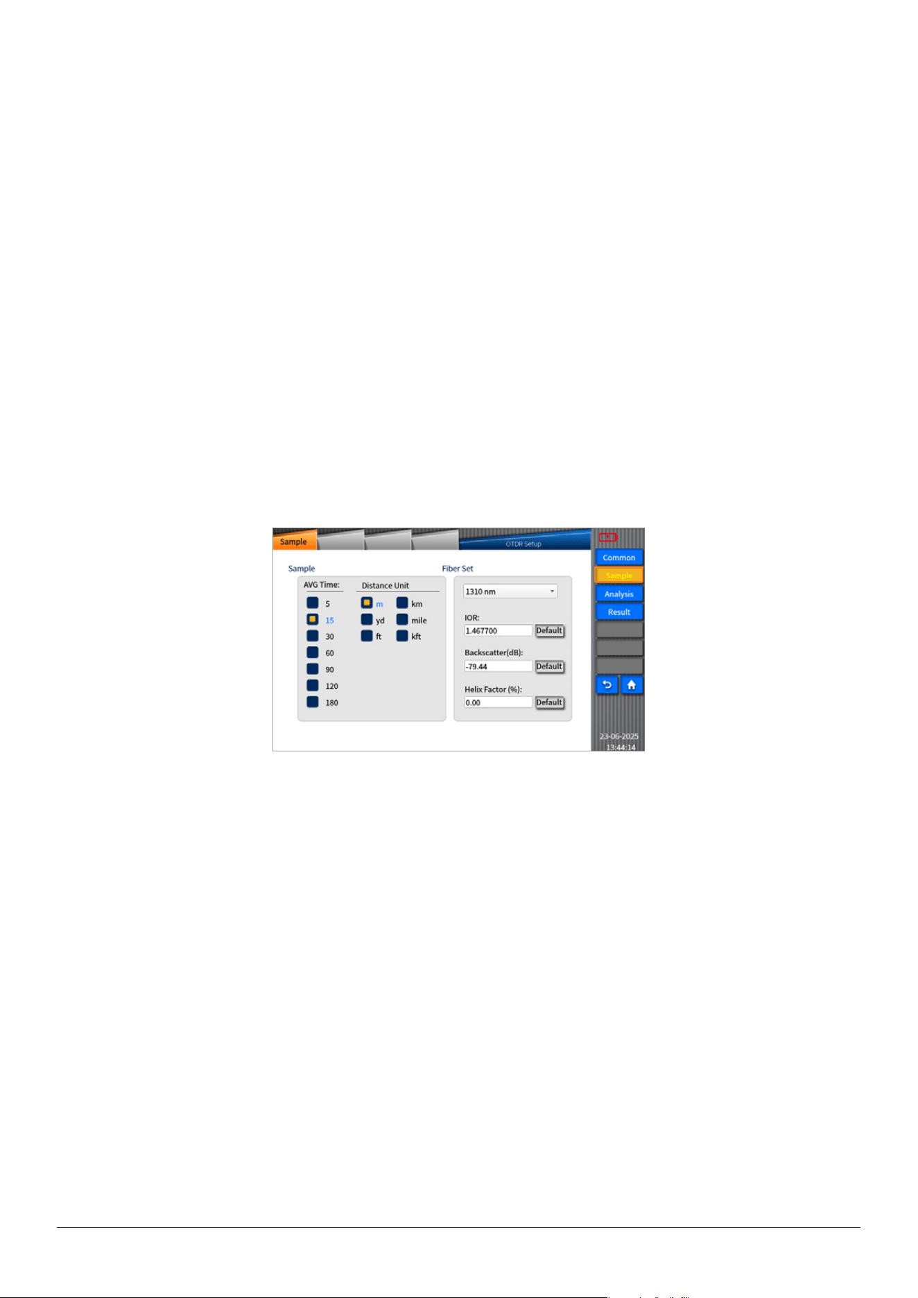
4.17Savelebydefault:
Clickthetextboxwithdirectorynameandthenenterthedefaultdirectory.
Picture1 Picture2
Youcanselectotherfolderandthenclickconrmationkeytochangethedefaultdirectoryasneeded.Youcanalsoclick“Create
folder”keyandthenclickconrmationkeytocreateanewdefaultdirectoryasneeded.
INNO user manual
28
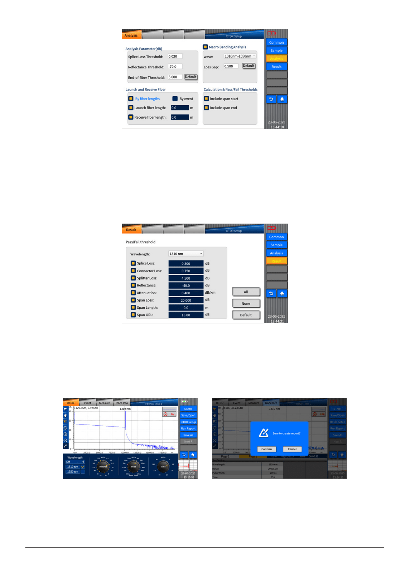
SampleSetting
1.“Sample”,includingoptionsof“SampleSet”and“FiberSet”,isusedtosetsampleparameterandberparameter.
2.SampleSet:tosettheAveragingtime,SamplingrateandconverttheUnits.
1)AveragingTime:tosetthemeasurementtimebydefault.
2)DistanceUnit:3typesofunitareavailableonVIEW400,i.e.m/km、yd/mile
ft/kft
3.FiberSet:TosettheIOR,Backscattering(dB),ExcessLength(%).Dierentnumericalresultscanbeobtainedafteranalysis
accordingtodierentsettings.(Note:ExcessLength(%):intheprocessofberlaying,partofopticalbershouldbereserved,so
infactthelengthofberislonger.)
1)IOR:ItreferstotheIndexofRefractionofthetrace,i.e.groupindex.Thedistanceofthetracewillvarydependingonthisparam-
eter.YoucaninputIORdirectlyonthisdevice.
2)Backscattering(dB):itreferstotheRBSofthetrace.ThereectanceandORLofthetracewillvarydependingonthisparameter.
3)ExcessLength(%):TosettheExcessLengthofthetrace.Thedistanceofthetracewillvarydependingonthisparameter.
AnalysisSet
“Analysisset”isusedtosettheparameterofanalysistrace.
1)SpliceLossThreshold(dB):Toanalyzethesmallnon-reectiveeventontrance.
2)ReturnLossThreshold(dB):Toanalyzethesmallreectiveeventontrance.
3)FiberEndLossThreshold(dB):Toanalyzetheimportantevenlossontrance.
AllthesetypesoflosswillaectthesignalCurveanalysis.
“Launchberandreceiveber”:
Thebeginningofthelinkundertestwillbemovedbackaccordingtothedistancesetupwhenlaunchberlengthisset.
Theendofthelinkundertestwillbemovedforwardaccordingtothedistancesetupwhenreceiveberlengthisset.
Macrobending,macrobendingworldjudgmentthresholdformulti-wavelengthdetection.
Doesthecurvecontainstart/endeventswhenitpassesthethreshold.
INNO user manual
29
ThresholdSetting
Thethresholdsaresetinordertojudgethe“eventpoint”andtheresultsof“pass/fail”regardingthe“berspan”arealsodis-
played.
Theresultsachievedaftermeasurementaredisplayedwithappropriatecoloringbasedonthepass/failstatusofeachvalue.
Thesetupparameterswillvarydependingondierentwavelengths.
Picture1 Picture2
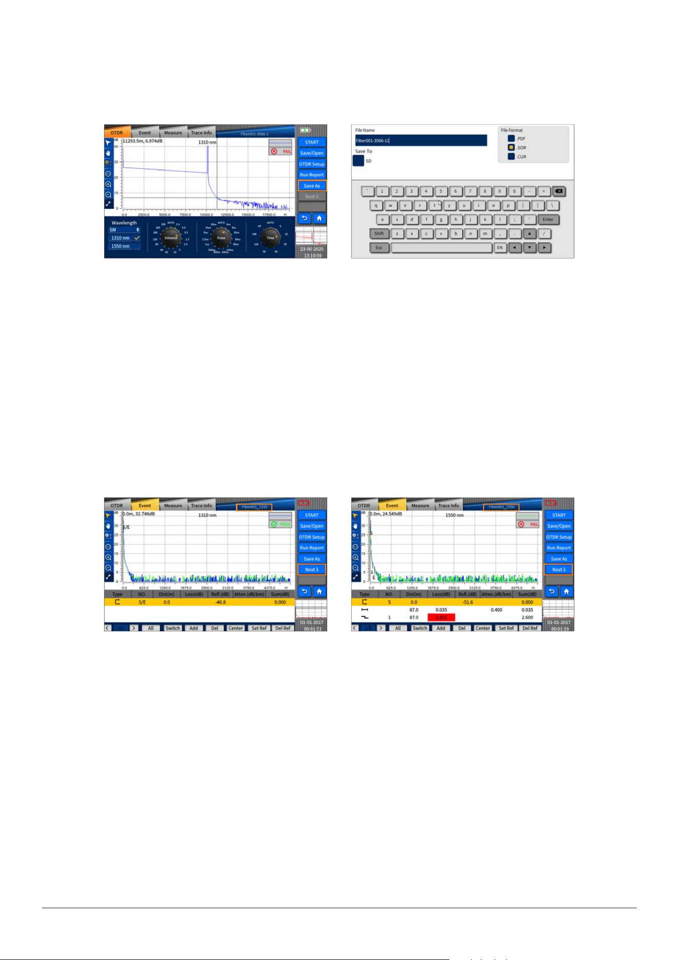
4.18RunReportkey
Asshowninthefollowingpicture,click“RunReport”andthenclicktheconrmationkeyinthepopupmessage.Untilmessage
indicatinglecreatingsuccesspopsup,youcanndthatapieceofPDFlehasbeencreatedinthedefaultdirectory.
Note:Thisfunctioncanonlybeenabledifthetraceexists,otherwisethisfunctioncan’tbeused.
INNO user manual
30
Picture1
Picture1
Picture2
Picture2
4.19Saveaskey
Youcanclickthe“Saveas”keytoenterthe“Saveas”menu,whereyoucaneditthelename,leformat,orselecttheletothe
USB.
Note:Thisfunctioncanonlybeenabledifthetraceexists,otherwisethisfunctioncan’tbeused.
4.20Nextλkey
Onthepremiseofobtainingtwotracesduringdual-wavelengthtesting,asshownonthepicture,youcanclick“Nextλ”toswitch
thetraceanditsinformation.thelename,leformat,orselecttheletotheUSB.
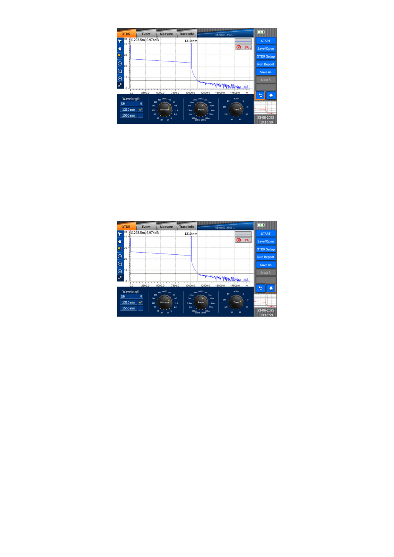
4.21Returnkey
Ifyouwanttoexitfromthecurrentoperatinginterfaceondierentoperationinterfaces,click“return”keytofastreturntothe
previousoperationinterface.
INNO user manual
31
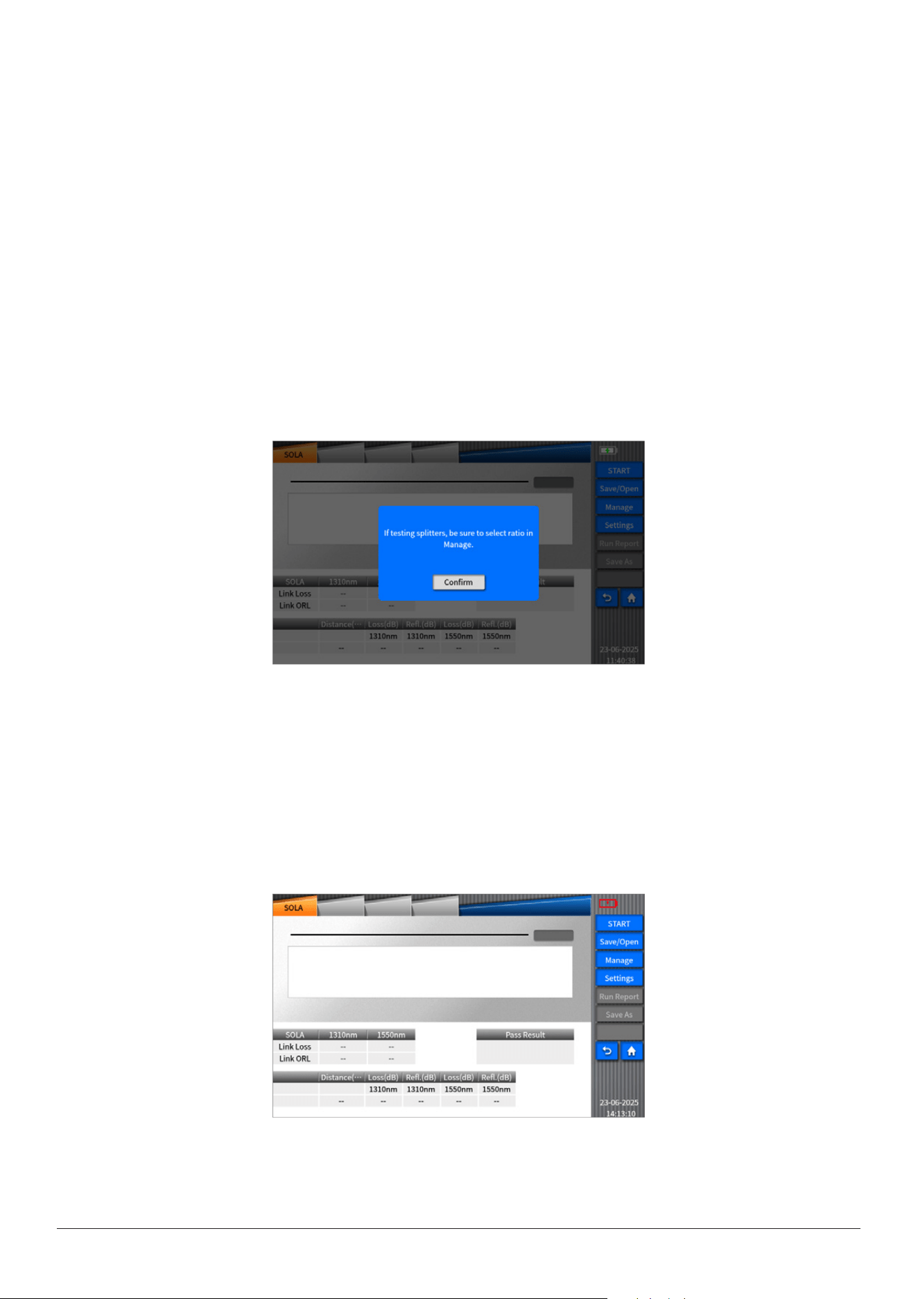
4.22Mainmenukey(Home)
Ifyouwanttoreturntothemainmenuinterfaceindierentfunctionmodules,clickmain“Home”keytofastreturntothemain
menuinterface,thenoperateothermodules.
INNO user manual
32
Chapter 5 SOLA
SOLA is based on an application program of OTDR. The design purpose of SOLA is to simplify OTDR test process: you don’t
need set parameters or start any other program for analyzing multiple and complicated ODTR traces because with its ad-
vanced algorithm, SOLA can dene dynamic measuring parameters and determine right numbers of traces acquired according
to the tested network, furthermore, it can associate multiple pulse widths of wavelengths to locate and recognize the fault of
the link with high resolution. All these functions described above can be realized only by pressing one key.
5.1 “SOLA” operation
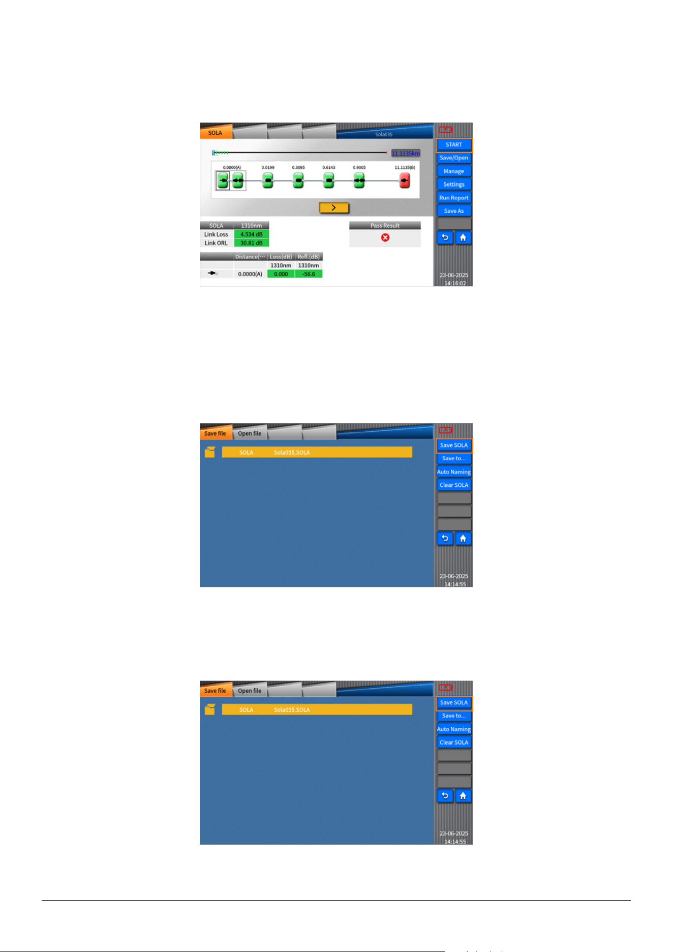
After module is selected and loaded, turn on the device and then click “SOLA” icon on VIEW400 main interface to enable the
SOLA function.(the SOLA performance will vary depending on the module changed)
Each time when you enter SOLA menu, pop-up message will appear: < Please specify SOLA Splitting Ratio before you use
SOLA>. Then you can conrm to access to the SOLA menu.
SOLA menu
The LinK Loss and Link ORL for each measurement with each wavelength on the optical ber link will be shown on the SOLA
interface.
LinK Loss: It refers to the total loss of the ber link measured. Link ORL : it refers to the ORL on the whole ber link.
INNO user manual
33
5.2 Start/ Stop
Youcanclick“Start”tostartmeasurement,orclick“Stop”tostopmeasurement.
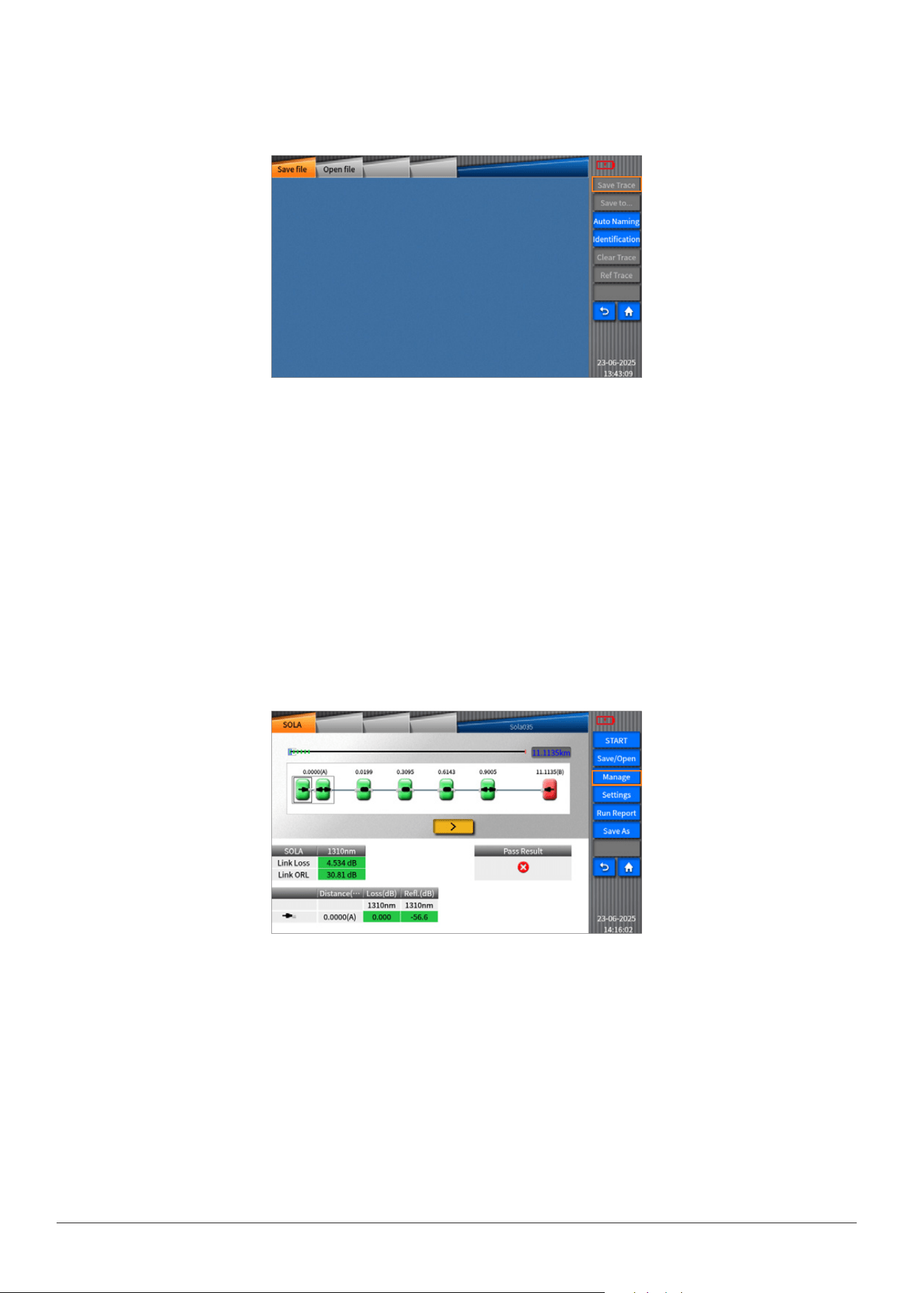
5.3 Save/Open
Youcansaveandreadthemeasuredtraceinthe“Save/Open”menu.
Enterthe“Save/Open”menubyclickingthe“Save”key,asshowninthefollowingpicture.
SaveSOLA
SavethetraceofSOLAleformattothedefaultdirectory.
INNO user manual
34
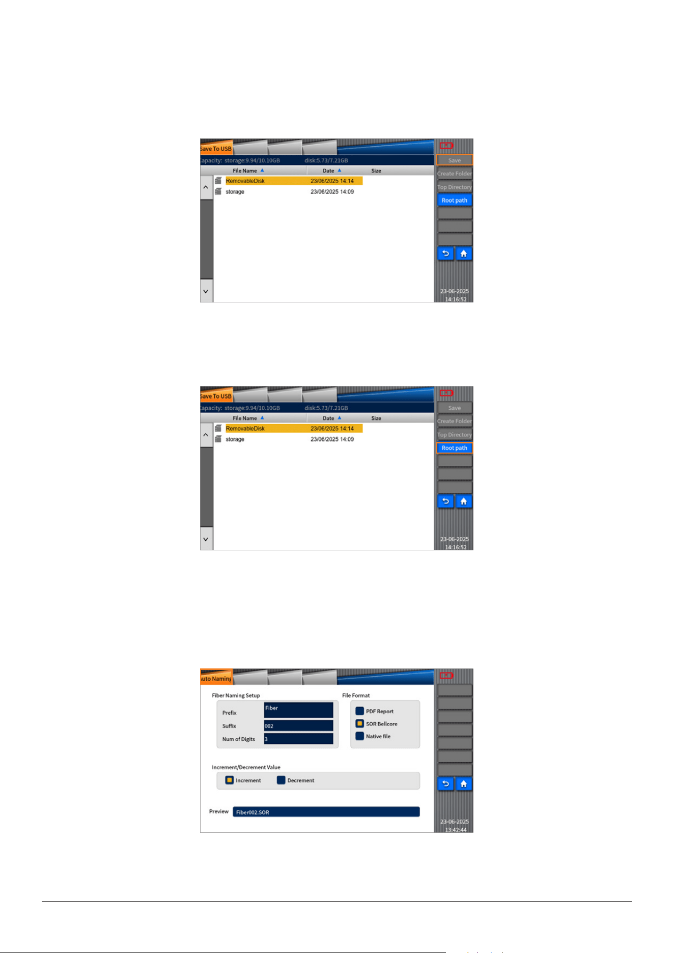
Saveto
SavetheletotheUSB.
Click“Save”tosavethele.
ClicktheQuitkeytogobacktothemenuoflesaved.
Youcanselectthedirectoryasneededbyclicking“Topdirectory”or“Rootpath”.
AutoNaming
YoucanchangenameoftheleandselectPDFreportandSOLAasaleformat.
INNO user manual
35
ClearSOLA
Ifyouclickthe“ClearSOLA”,thelenameandtracedisplayedwillbeclearedtogether.
OpenFile
YoucanopenthesavedSOLAleinthedefaultdirectoryorintheUSB.Select“open”toopentheselectedle;SelecttheQuit
keytogobacktothemenuofles.
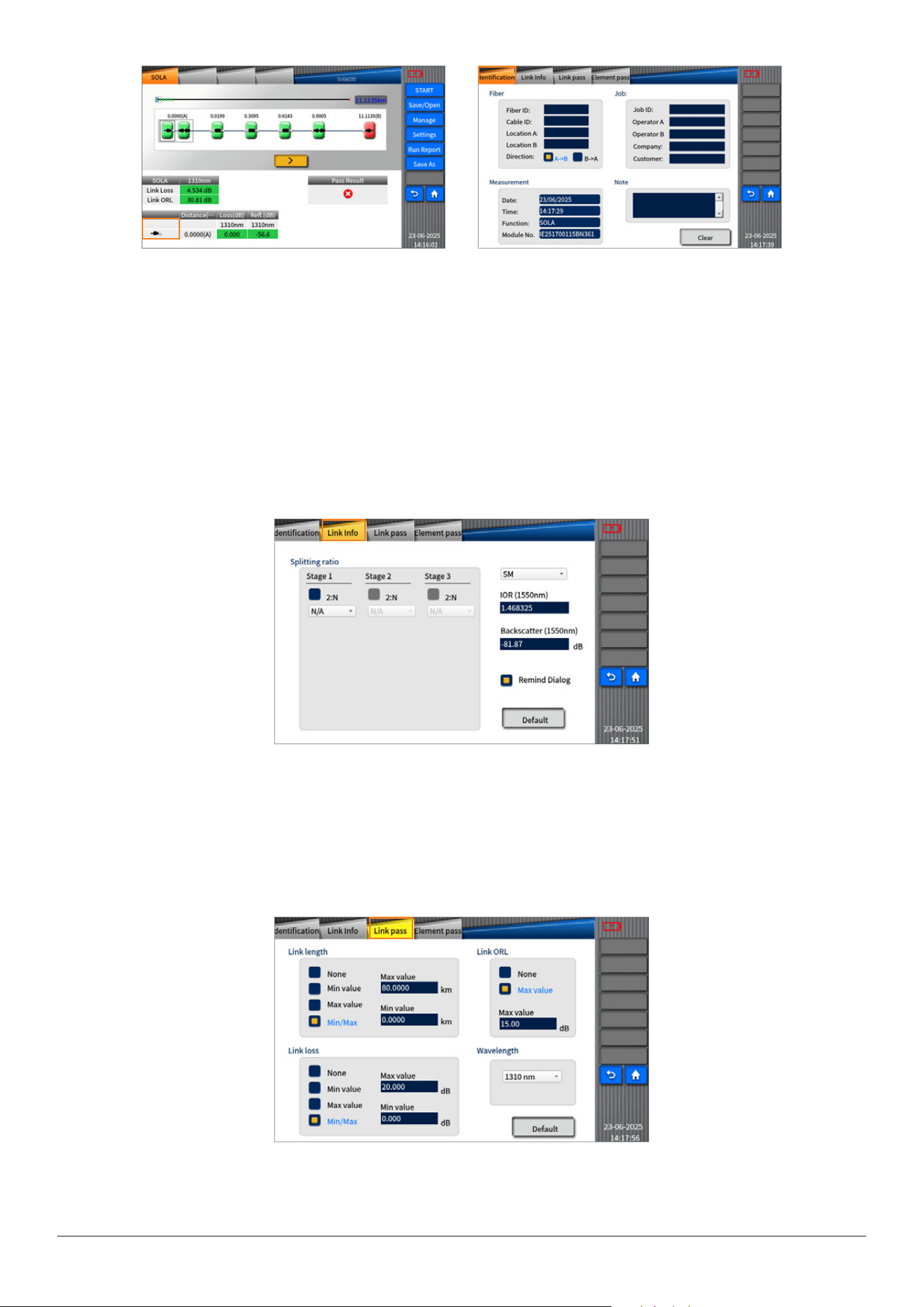
5.4Management
Asshowninthepicture,youcanenable“management”functionbytappingon“setup”keytosetrelatedmeasuringparameters
suchas“identication(identify)”,“linkdenition(linedene)”,“linkpass(linepass)”,“elementpass(itempass)”.
Identication
IfyouentertheIdenticationmenubyclicking“Manage”,thecorrespondingrecordsofthelessavedafterSOLAmeasurement
canbeshown.
INNO user manual
36
Linedenition(Linkinfo)
Youcanmanuallysetberlinkdenition,includingselectinglevelsofsplittingratio,adjustingrelatedmeasuringparameters.
IOR:ItreferstotheIndexofRefractionofthetrace,i.e.groupindex.Thedistanceofthetracewillvarydependingonthisparame-
ter.YoucaninputIORdirectlyonthisdevice.
Backscattering(dB):itreferstotheRBSofthetrace.ThereectanceandORLofthetracewillvarydependingonthisparameter.
Picture1 Picture2
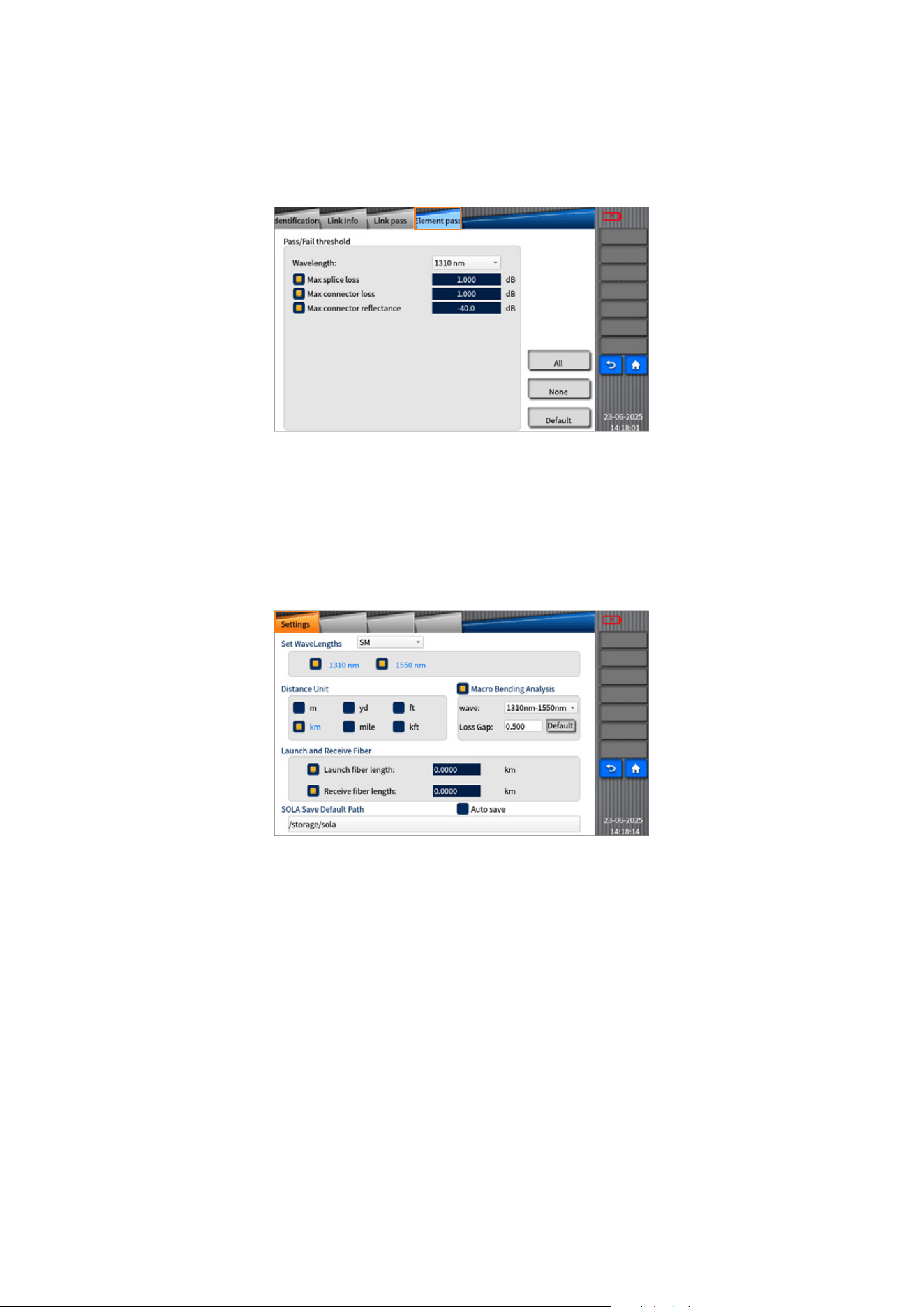
LinePass
Youcanmodifyrelatednumeric,includingadjustingtheconditionsofmeasurementlinkandthethresholdsofpass/failed.
INNO user manual
37
ElementPass
Youcanmodifytherelatedthresholdstojudgewhethertheelementsarepassedorfailed.
Forexample:Whenyouwanttomodifymaxspliceloss,directlyclickthevalueinintersection,andthenyouwillseeapop-upbox
forvalueinputonthescreen(Relativemessagewillbeshownwhenthevalueenteredexceedsthelimit.)
Clickalltoenableallthresholds;clicknonetodisableallthresholds;clickdefaulttoreturntothedefaultvalue.
5.5Settings
IntheSettingsmenuofSOLA,youcanselectthewavelength,andsetthelengthsofLaunchFiberandReceiveFiber,asshownin
thefollowingpicture.
5.6RunReport
Selectthe“RunReport”tabtosavethecurrentSOLAleinPDFformat.
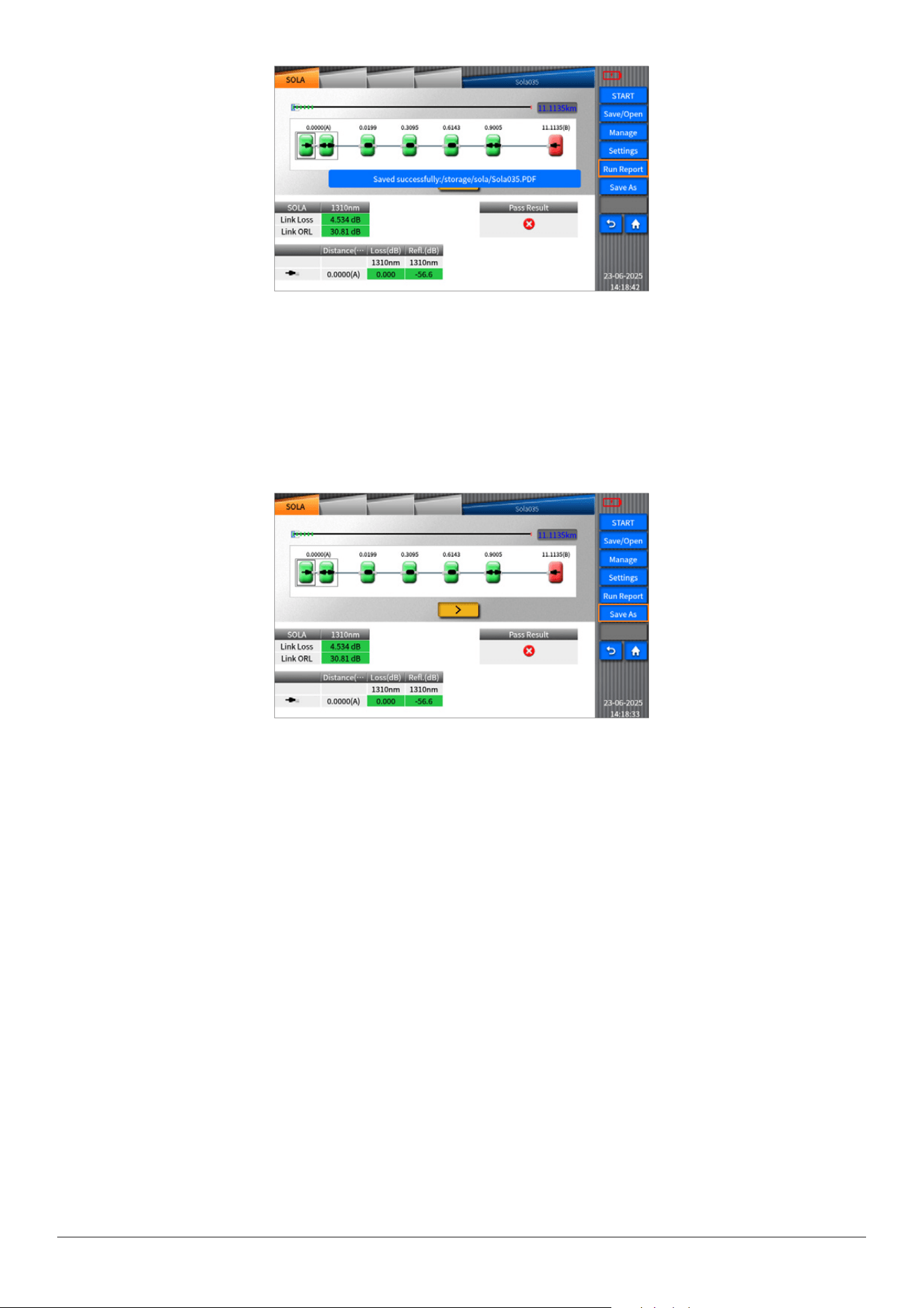
INNO user manual
38
5.7Saveas
Youcanclickthe“Saveas”keytoenterthe“Saveas”menu,whereyoucaneditthelename,leformat,orselecttheletothe
USB.
INNO user manual
39
Chapter 6 Optical Power Meter
6.1Overview
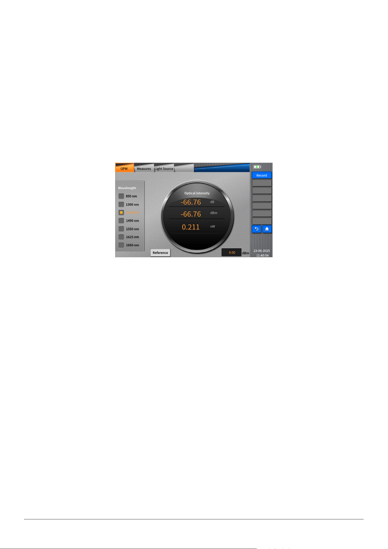
Theopticalpowermeterofhighaccuracyisusedtomeasureabsoluteopticalpowermeterorrelativeopticalpowerlossthrough
aspanofopticalber.Thismodulecanmeasureopticalpowerofmulti-wavelength.Itcanbeoperatedeasily.
Referencevalue(OPMonVIEW400):youcansetthereferencevalueintheOPMinterface.(Youcansetavalueasareferenceto
calculatethecurrentvalueofopticalpowerwhichwillbedisplayedattherstlineinthecircle.)
6.2OPMOperation
•
ConnectthelightsourcetoOPMportwithaberjumperconnector.
•
Click“OPM”inhomemenutoenteropticalpowermeterinterface,aspictureshows.
INNO user manual
40
Chapter 7 Light Source
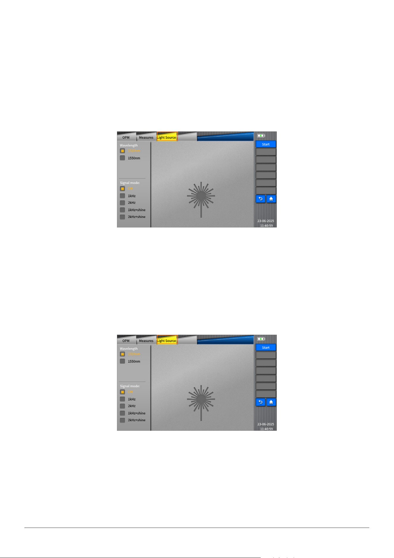
Thelightsourcemodulecanprovideinvisiblelightsource(thewavelengthandpowerdependonthetypeofmoduleselected)
andthetypesoflightincludeCWlight,1KHZlight,2KHZlight,1KHZblinklight,2KHZblinklight.
•Selectwavelengthoflightsource(1310/1550nm)bytappingontheupperleftsideofthescreen;selectemittinglightsource
modes(CW/1KHZ/2KHZ/1KHZ
+blink/2KHZ+blink)bytappingonthelowerleftsideofthescreen;afterthat,tap“open”keytoopentheinvisiblelightsource.
•Turno“lightsource”:pleasetapon“close”keyontherightside.
Warning:Theeyes’focusingonVIEW400lightsourceortheberendconnectedtolightsourceisforbidden,whichmaycause
damagetoeyes.
7.1Overview
ThetypesofsourceofVIEW400includevisuallightsourceandlightsource.
StableLightsource(LS)
Youcanclick“LightSource”toenablethelightsourcefunction.
7.2lightsourceoperation
•Connectthebertobetestedtothelightsourceport.
•Tapthelightsourceicononthemaininterfaceandthenselect“lightsource”toenterintotheinvisiblelightsourceinterface;
pleaserefertothefollowingpicture.
INNO user manual
41
Chapter 8 Fiber Microscope
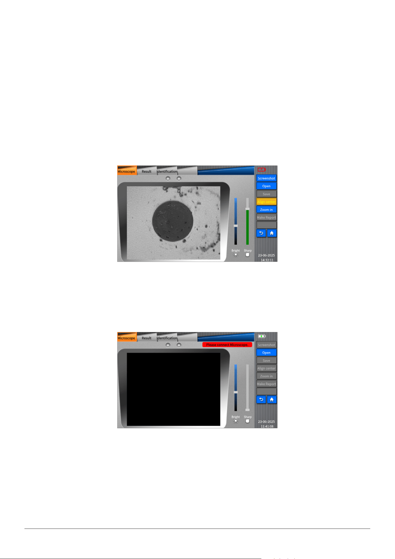
Notice:IftheberinspectionprobehasnotbeenconnectedsuccessfullytotheView400,themessageof“Pleaseconnectber
inspectionprobe.”willappear.However,theGDMlecanstillbeopened.
8.1Overview
Thegrindqualityandcleanlinessoftheberconnectingendfacecanbeinspectedwiththeaidofthemagniedsurfaceview
displayedonthescreenofVIEW400.
8.2Startberendinspection
Afterconnectingtheberinspectionprobe,click“FiberMicroscope”onVIEW400maininterfacetoenterintotheinspection
interface.Pleaserefertopicture
8.3Thefunctionofbermicroscope
Thefunctionsoftheberinspectionprobe(bermicroscope)include“screenshot/realtime(video)”,“open”,“save”,“Align
center”,“Zoom”,“MakeReport”,“Result”and“identication”.
•“screenshot/realtime(video)”functionisapremiseof“save”.Afterconnectingsuccessfullythedevice,youcannotenable
“save”functionuntil“screenshot/realtime”softkeychangesto“realtime”.
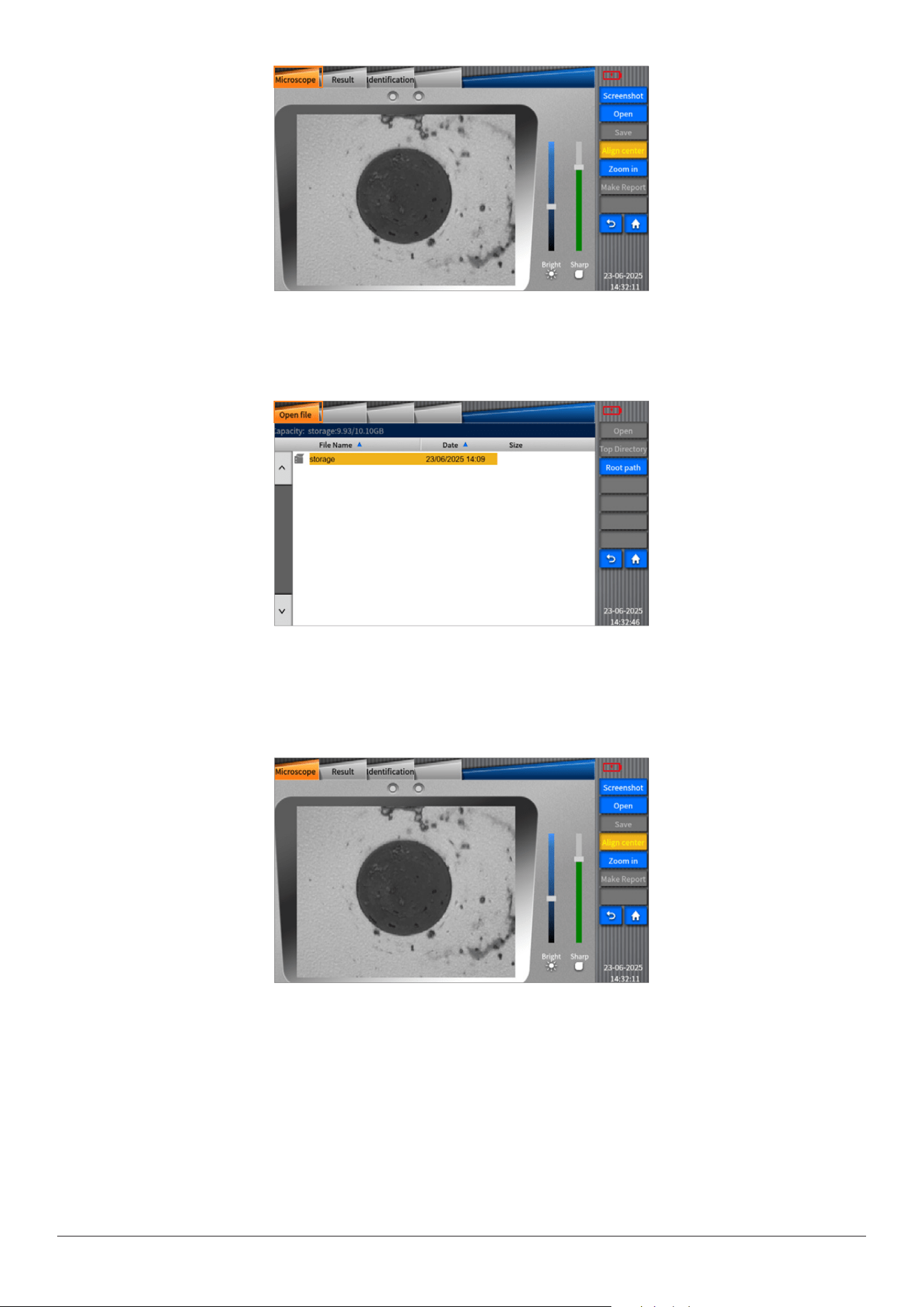
INNO user manual
42
•“Open”functionisusedtoopenthelesalreadysaved.
•“Aligncenter”functionisusedtoplacetheimageinthemiddleofthescreen.“Zoomin”functionisusedtoamplifytheactive
displayedimage.
•“Makereport”functionisusedtosaveananalysisreportofle.
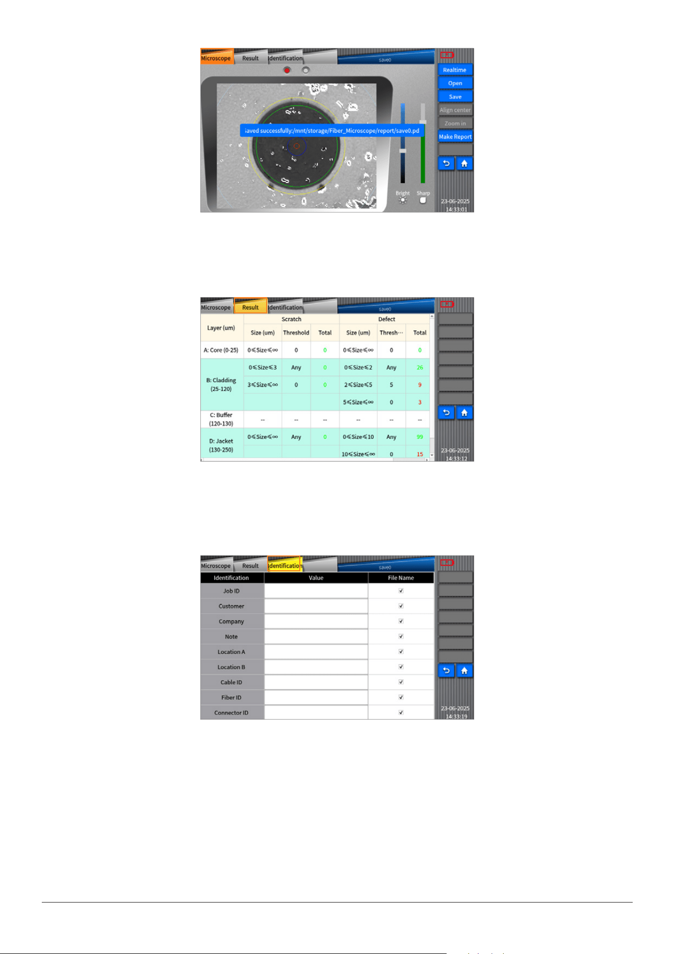
INNO user manual
43
•“Result”functionisusedtoanalyzetheactiveimageandshowtheresultsintheformoftables.
•“Identify”functionisusedtosetrelatedinformationdisplayed,thecontentsofwhichareuser-denable.
8.4Checkthepreservedimage
•Clickthelemanagementicononthemaininterface.
•Selecttheimagesavedpath(thesavingpathforVIEW400issettobe:storage\Fiber_Microscope).
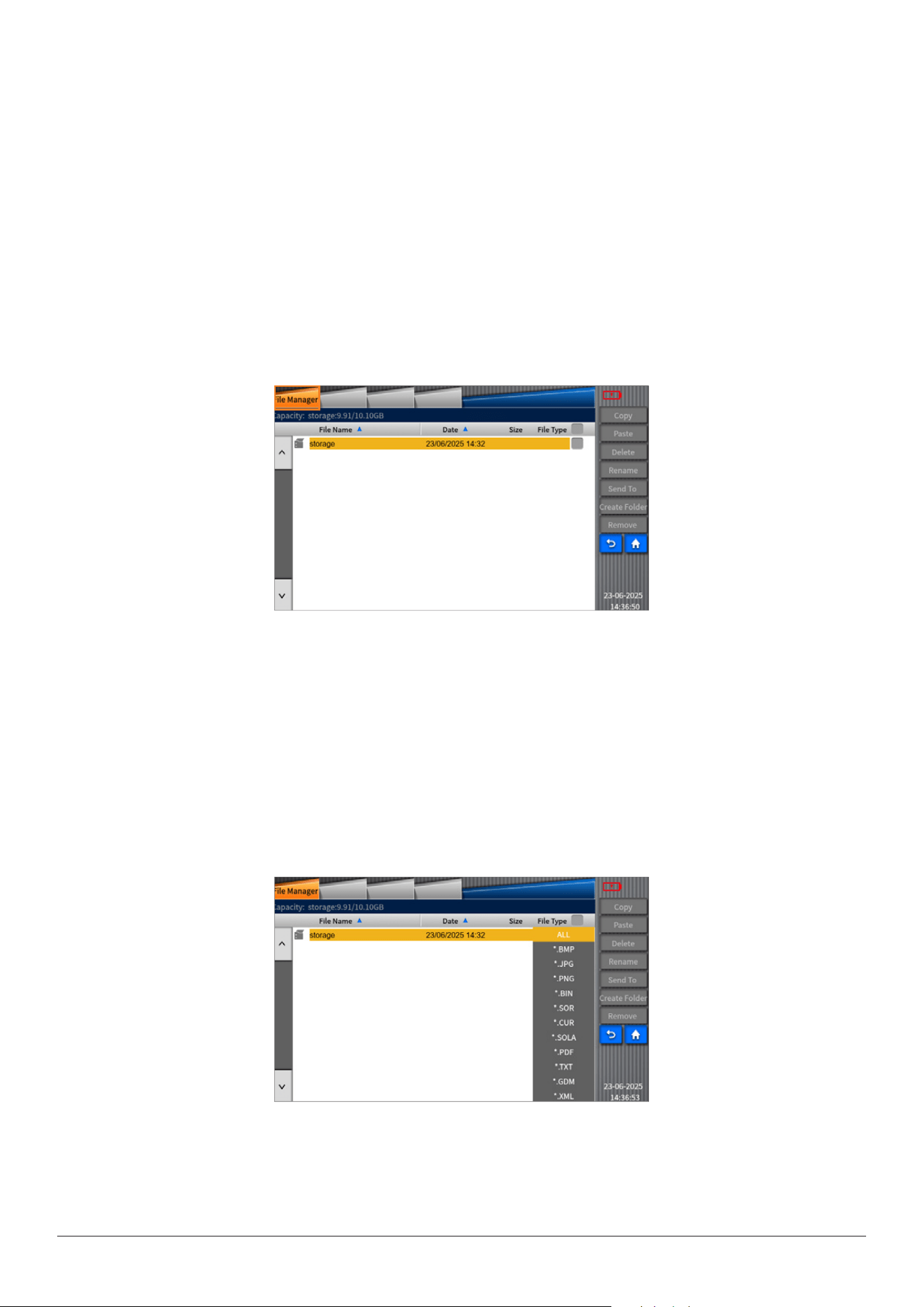
INNO user manual
44
Chapter 9 File Management
9.1Overview
“Filemanagement”isusedtoviewthesaveddataandcarryoutoperationslike“copy,delete,rename,createfolder”.Allthe
operationstothelesshouldbecar-riedoutindirectoriesoftheinternalstorageandUSBstorage(ThedirectoriesofVIEW400
aresdcarandusb).
9.2Startlemanagement
Click“FileManager”onmaininterfaceofVIEW400toenterintothelemenu.
9.3Filemanagerfunction
Therearefollowingitemsinthismenu,suchasFileName,Date,andTypesofFile.FileName:ClicktheFileNametosorttheles
byname.
Date:ClicktheDatetosortthelesbydate.
FileType:ClicktheFileTypetosortthelesbytheirtypes.
Thetypesoftheleinclude:SOR,BMP,JPG,SOLA,HTML,TXT,GDM,PDF,CUR,BIN
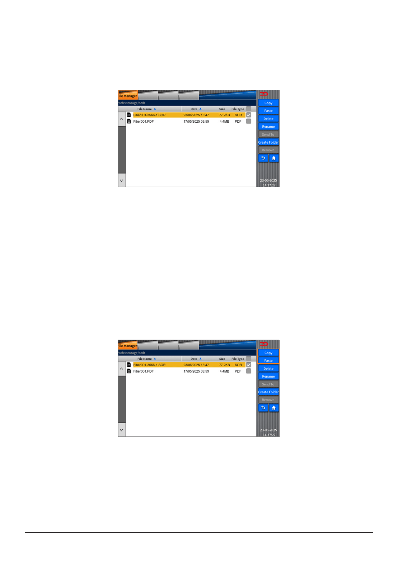
INNO user manual
45
•COPY/PASTEkey
SelectoneleandthenclickCopytocopyonele.Or,ifusersneedtoselectallthelestocopyallofthem,justselectthebox
aftertheFileType.
OperatingSteps:
a)ClickFILETYPEtoselecttheletypeneededtobecopied
b)Clickandaccesstotherootdirectory(sdcard/usbdirectory)
c)ClickCopyafterselectingsubdirectoryorle(PASTEcannotbeexecutedifnosubdirectoryorlebeingselected)
d)Selectthetargetdirectoryneededtobecopied
e)ClickPASTE.However,PASTEcannotbeexecutedunderthesamedirectory.Thenotice“Youcan’tcopyletothesamedirecto-
ry!”willappearsonthescreen.
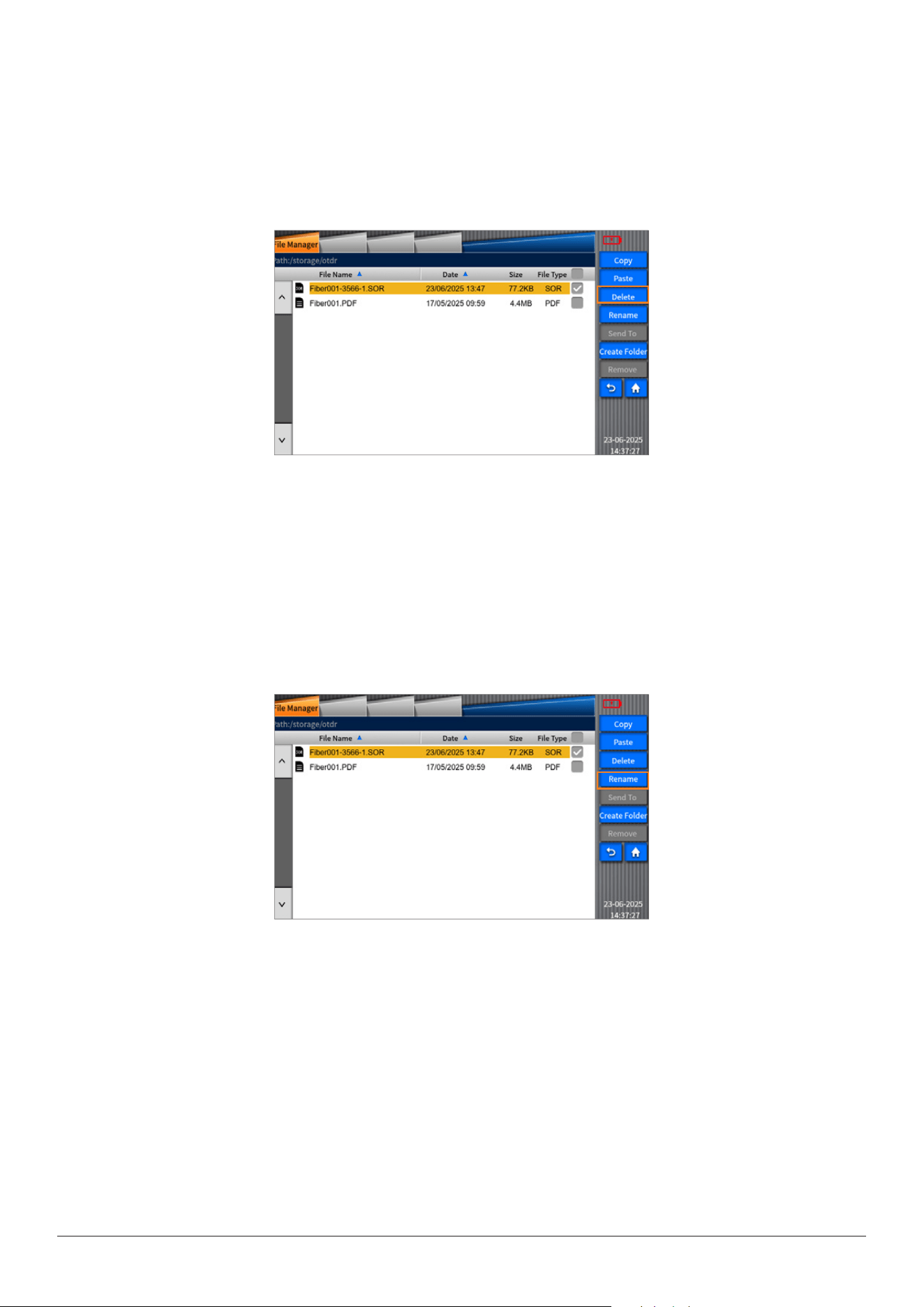
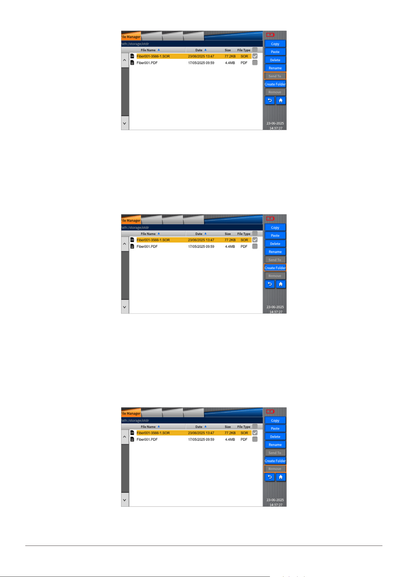
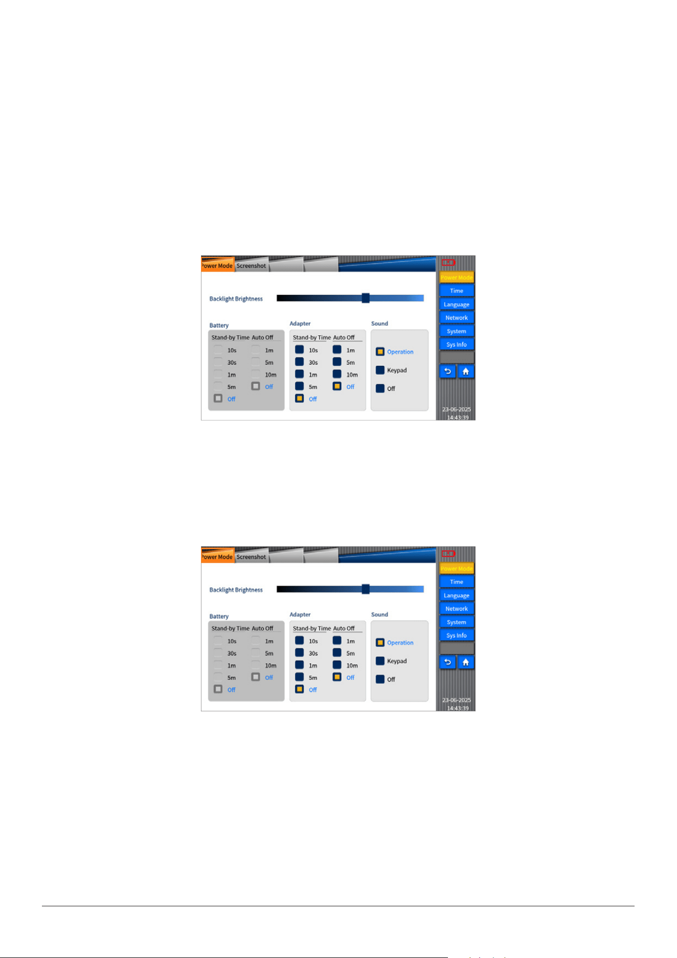
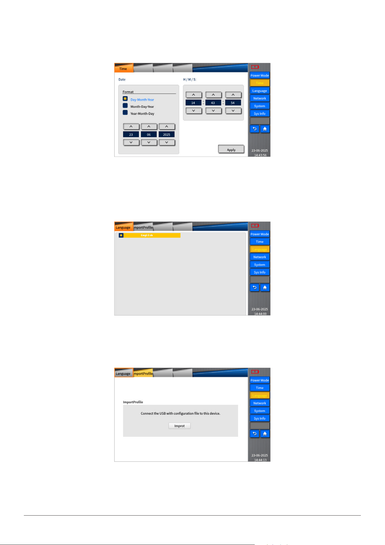
9.4“Operate”Function
Therearefunctionsof“copy”,“paste”,“delete”,“rename”,“SendtoUSB”,and“createfolder”and“removeUSB”includedin
operationinterface.
INNO user manual
46
•DELETEkey
Itcandeletethelesorsubdirectoryinthedirectory.Operationsteps:
a.ClickFILETYPEtoselecttheletypeneededtobedeleted
b.Clickandaccesstotherootdirectory(sdcard/usb)
c.SelectfolderorlestoexecuteDELETE
•RENAMEkey
Itcanrenamefolder,leandleformat.Operatingsteps:
a.ClickFILETYPEtoselecttheletypeneededtoberenamed.
b.Clickandaccesstotherootdirectory(sdcard/usb)
c.SelectfolderorletoclickRENAME,accesstotheinputinterfacetoeditthename.
d.Press“ENTER”
•SENDTOFOLDER
ThekeyofSendToUSBisusedtosendthelesorfoldersselectedtothefolder.
INNO user manual
47
•CREATEFOLDERkey
Itcancreateasubfolderunderthecurrentfolder.Operationsteps:
a.clickandaccesstotherootdirectory(sdcard/USBdirectory)
b.ClickNEWFOLDERtoenterintotheinputinterface,andtheninputthefoldernamethenpressENTERtocreateafoldersuccess-
fully.
•REMOVEDEVICEkey
UserscanusethiskeytoremovetheUSB.Operatingsteps:
a.ClickRemoveUSBkey.
b.ThefunctionofthekeyofRemoveUSBisdisabled.
INNO user manual
48
Chapter 10 System setting
10.1Overview
ThesystemsetupfunctionthatVIEW400hasoeredcanlettheusermodifythesystemparametersasrequired.
10.2Systemsetting
Click“Setting”onthemaininterfaceofVIEW400toenterintothe“systemsetup”interface.
10.3Functionsofsystemsettings
Therearefunctionssuchas“standbyandbrightness”,“time”,“language”,“WIFI”,“printer”,and“systemmaintain”inVIEW400
systemsettingmenu.
StandbyandBrightness
1)Backlightbrightness Setthebackgroundbrightnessforthescreen.
2)Batteryandadapter Setthestand-bytimeandautopower–otimewhen
usingbatteryoradapter.
3)sound Setthemeasurementwarningsoundandkeywarningsound.
INNO user manual
49
Time
Youcanuse“time”functiontosetthetimethatisdisplayedonthedevice.
Language
The“language”functionisusedtosetthelanguagesdisplayedonthescreen.
Youcanselect“ImportProle”tocongurethemulti-languagesbythePC.
INNO user manual
50
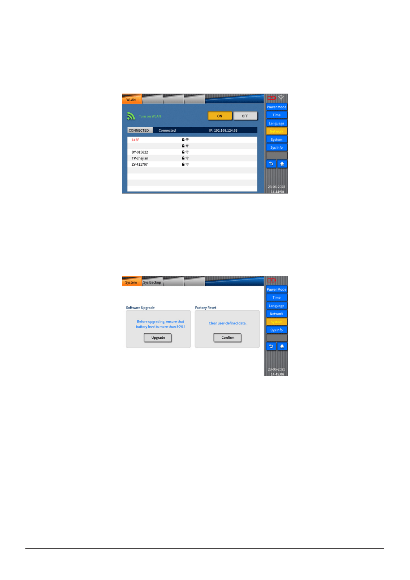
WI-FI
“Wi-Fi”functioncanbeusedtoconnectthedevicetolocalareanetwork(LAN),realizingwirelessinternet.
Underthisfunction,alongwithuppercomputer,wirelessletransmissioncanbe
realized.(PleaserefertotheWi-FiInstructionfortheusageindetail.)
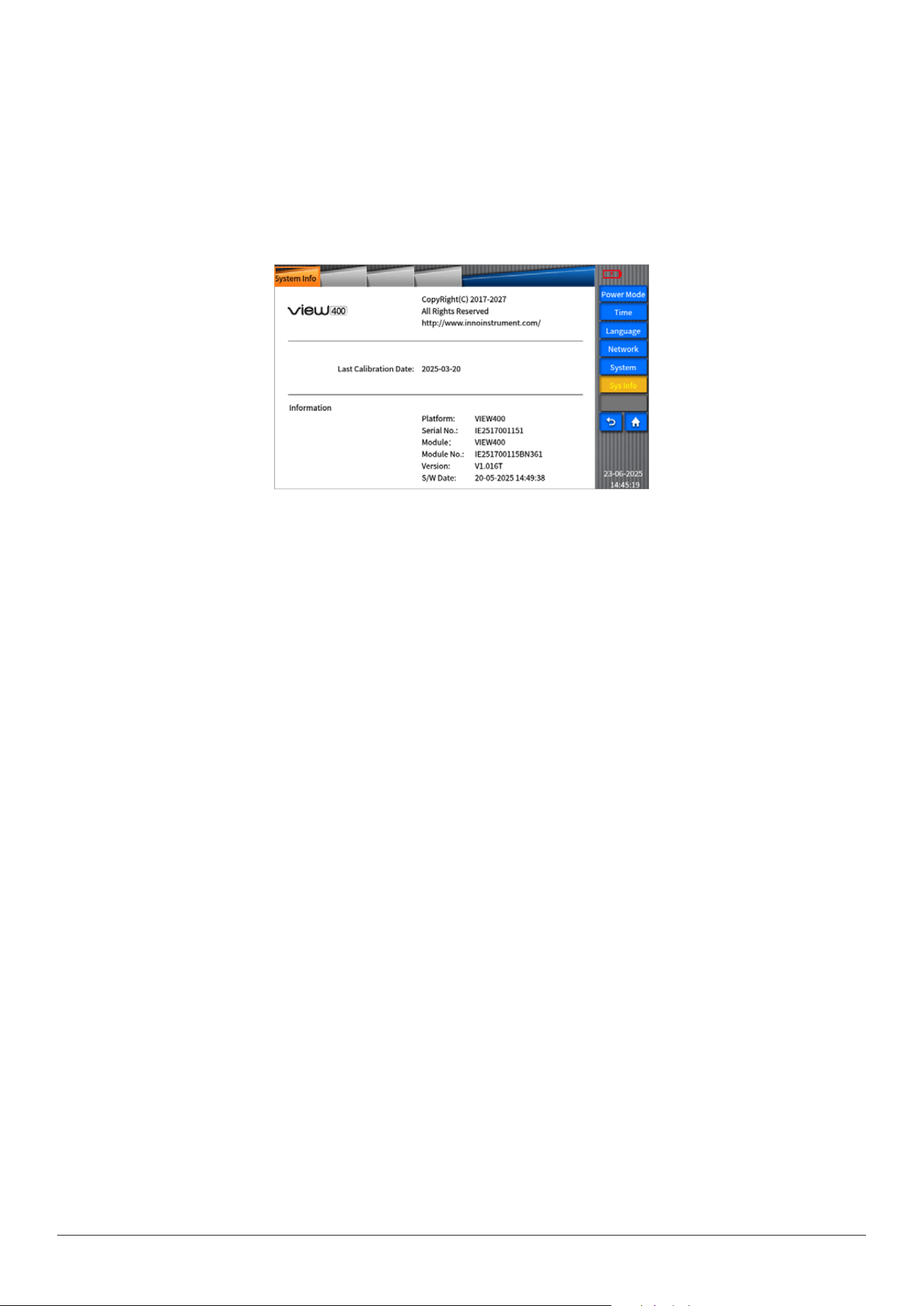
Systemmaintenance
Therearetwofunctionsin“systemmaintenance”,whichare“softwareupgrade”and“factoryreset”.Pleaserefertopicture.
•“Softwareupgrade”canbeusedforthesoftwareupgradeanddegradation.Operationsteps:
•InserttheUSBwithletobeupdatedandpoweradaptertoVIEW400portrespectively.
•Click“Systemmaintain”onsystemsetupinterface.
•Click“Upgrade”.thenitwillshowupgradenotice;andthenclick“conrm”tocarryoutupgradeoperation.
Note:Beforeupgrading,ensurethatbatterylevelismorethan50%!
•“Factoryreset”isusedtorestorethesystemparameterstotheoriginal.
INNO user manual
51
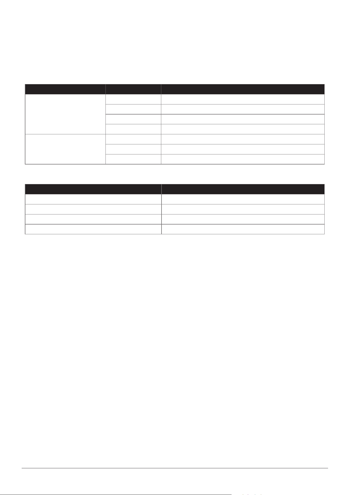
Chapter 11 System Information
11.1Systeminformation
Asshowninpicture,thisinterfacedisplaystheinformationabouttheproductsandmanufacturer.
INNO user manual
52
Attachment
1. Structure requirement
1) Display screen: 5inch (800 x 480)
2) Indicator light (2 pieces)
2. Hardware interface requirement
• DC INPUT: Power port
• USB port (1 piece): Save data and connect the ber inspection probe
• Optical interface: interchangeable port (FC, SC)
• OPM port: FC2.5mm universal interface
3. Software interface requirement
• Interface mode: button input or touch screen input
• Operating platform: Linux
4. Operating environment requirement
• Temperature requirement:
Working temperature: -10℃ ~ 50℃ Storage temperature: -20℃ ~ 60℃
• Humidity requirement: (general standard)
Operating humidity: 0% ~ 45%, non -condensation
Storage humidity: 0% ~ 95%, non -condensation
5. Performance requirement
3) Keys (4)
4) Operating time>8h, charging time<4h
Indicator light State Function
Chargelight
(Red)
Normallyon Batteryfull
Flashing2Hz Adapterpowersupply
Flashing1Hz Batterycharge
OFF Removetheadapter,andusebatterypowersupply
Powerlight
(Green)
Normallyon Startingup
Flashing Lowbattery
OFF OFF
Names of buttons Quantity
POWER 1
MENU 1
START 1
ESC 1

INNO user manual
53
Module Technical index Value
OTDRmodule PleaserefertotheparametersofOTDRmodulepurchased.
Sola PleaserefertotheparametersofOTDRmodulepurchased.
FiberMicroscope Interchangeableport
(FC,SC)/PC
(FC,SC)/APC
OPM
Detectortype InGaAs/GeGeX
Typeofberinterface Support2.5mmuniversalinterface
Wavelengthcalibration
850/1300/1310/
1490/1550/1625/1650nm
Measurementrange -70to+6dbm
Accuracy 0.01dB
Unitsdisplayed dB,dBm,nW,uW,mW
Module Parameter
OTDR
FiberType G.652ber
WaveLength 1310nm±20nm、1550nm±20nm
MaxDynamicRange 36dB(1310nm)、35dB(1550nm)
EventDeadZone 0.8m
AttenuationDeadZone 3m
TestRange
100m/300m/500m/1.3km/2.5km/5km/10km/20km/40km/80km/120km/
160km/260km/320km
PulseWidth 3ns/5ns/10ns/30ns/50ns/100ns/200ns/300ns/500ns/1us/2.5us/5us/10us/20us
DistanceUncertainty ±(0.75m+SamplingResolution+0.0025%×TestDistance)
Linearity ±0.05dB/dB
SamplingPoints 150000
SamplingResolution 0.04m~10.24m
LossResolution 0.001dB
LossThreshold 0.02dB
DistanceResolution 0.01m
RefractiveIndex 1.000000~2.00000
Format SOR,PDF,CUR,SOLA
LossMeasurementMode TPA/LSA
LaserSafetyLevel ClassⅡ
OpticalConnector SC/APC(InterchangeableFC、LC)
SOLA
Wavelength 1310/1550nm
MeasuringRange 0~150km
Max.SplittingRatio 1:128splitter
Light source
ExportWavelength ConsistentwithOTDRexportwavelengths
LaserType ConsistentwithOTDRtype
ExportPower ≥-5dBm
Stability CW,±0.5dB/15min(After15minofpreheating)
OpticalConnector SC/APC(InterchangeableFC、LC)
OutputMode CW/1kHz/2kHz/1kHz+shine/2kHz+shine

INNO user manual
54
OPM
WavelengthRange 800nm~1700nm
CalibrationWavelength 850/1300/1310/1490/1550/1625/1650nm
MeasurementRange -70~+6dBm
Resolution 0.01dB
Uncertainty ±5%
OpticalConnector UniversalFC/SC/ST
Common index
Display 5inch,800×480,TFT-LCD,Multitouchcapacitivetouchscreen
PowerSupply
AC/DCadapt:Input:100V~240V,50/60Hz,1.5A
Input:19V,3.42A,lithiumbattery:7.4V,4300mAh
BatteryLife standby>10h,continuoustest>7h
SaveData Internal:16GBEMMC,External:SupportsUSBashdrive
ChargingInterface DC2.5mm
OtherConnector USB2.0
WirelessNetwork WIFI
WorkingEnvironment -10℃~+50℃
StorageTemperature -40℃~+70℃
RelativeHumidity 0~95%NonCondensing
Weight ≤795g
Size 172mm×111mm×64mm

INNO user manual
55
Term list
Thistermlistgivesexplanationsaboutberandrelateddevices.
B
• Backscattering: The scattered light which opposes to the previous direction of propagation.
• Bandwidth: The function size transmitted by waveguide drop 3db below the zero frequency. The lowest frequency bandwidth
is the function of waveguide length, but it is not in direct proportion to the length.
C
• Coating layer: A kind of material coated on the optical ber in wire drawing pro- cess to prevent ber damaged from
environment or improper operation.
• Cladding: Insulating materials coated on the ber cores.
• Cable pipelines: The pipeline for cable to pave or from it the pipe can be pull.
• Cable bending radius: Cable bending radius refers to the stress load that cable suered, free bend refers to the admissible
diameter for it lies under no burdened state.
• Cable module: The kind of cable installed by connectors on one end or both ends, this kind of cable often used as the
interconnection by cable system and optoelectronic devices. If there is only one end installed by the connector, we call it “tail
end ber”. If both ends installed, we call it “bridging cable or wire jumper”.
D
• Decibel (dB): Standard unit used to describe the optical power gain or loss.
• Dielectric: It belongs to nonmetal type, so it is non-conducting, glass optical ber is deemed as a kind of dielectric. Medium
cable contains no metal parts.
F
• Fiber core: The central area where light propagates through it. Fiber core ec- centricity ratio: The core center displacement
measurement relative to the cladding center.
F
• Fiber core: The central area where light propagates through it. Fiber core ec- centricity ratio: The core center displacement
measurement relative to the cladding center.
• Fiber core ellipticity: The deected measurement for aspheric ber core and perfect circle.
I
• Insertion loss: Due to the insertion of optical module ( the connector or coupler in optical transmission system) that result in
attenuation.
M
• Material dispersion: The dispersion resulted from material refractive index or the correlation with light speed and wavelength
in this material.
• Module (1): Used to describe the terms about the independent light path which penetrate the bers, such as multimode and
single mode.
• Module (2): Scattered light wave can transmitted in optical waveguide, it is the dierential equation eigenvalue featured
in waveguide. There is only one module which can transmit in single mode optical ber called “basic mode”. But there are
hundreds of modules in multimode bers; they are dierent in graph and propaga- tion speed, the upper limit of module
quantity determined by ber core diameter and waveguide value.

INNO user manual
56
• Monochrome:Composed by single wavelength, in fact radiation is not the ideal monochrome. The best situation is to display
wavelength in narrow-band range.
• Multi optical ber and cable: The cable contains two or more pieces of optical ber.
• Multimode ber: A kind of optical waveguide. Through it, light can be transmited by multimode. Typical ber core or covering
size is measured in micrometers. (62.5
/ 125).
N
• Nanometer: A kind of measurement unit, equal to nm, often used to describe wavelength, such as 1300nm.
O
• OTDR: OTDR transmit impulse to ber to measure backscattering. Through analysis the track can determine the event.
• Optical Time Domain Reectometer (OTDR): A kind of device used to measure the optical features in optical pulse
transmission, and make measurement of the back scattering light and reected light as the time function. This device can also
be used as the function relationship to estimate damping coecient and distance, determine the aw and other part loss.
• Optical ber: A kind of threadlet or ber made by any derivative light dielectric.
• Optical ber link: Optical ber transmission channel designed to connect either terminals or tandem with other channels.
• Optical cable: The module constituted by the materials which can protect the optical ber and resist to machine or
environment damage.
P
• Plug-in board: Network devices in the bracket, such as OTDR or the switches.
• Photoelectric device: A kind of device can response to ber power, send or adjust optical radiation, or used in internal work.
It can also be used as any device in photoelectric conversion.
• Port: Located at the port of the plug-in device to connect the wire jumper or the ber.
• Peak wavelength: The wavelength when the source optical power meter maxi- mizing.
S
• Single mode optical ber: The ber with small size core diameter called “single mode optical ber, usually it is 9um. Among
them only the single mode and basic mode can transmit this kind of ber. This kind of optical ber is particularly applied to
long-distance bandwidth transmission, for the bandwidth is only restricted by dispersion.
T
• Transmitter: A kind of driver can switch electric signal to optical signal.
• Transmission loss: Total loss in system when transmission happens.
• Telecom cabinet (TC): It is an enclosure space placed by cross-linked ber terminal and telecom settings. Equipment cabinet
is regarded ascross-link by main wiring and horizontal wiring.
W
• WDM: Transmit several signals in optical waveguide with dierent wavelengths at the same time.
FCC RF Radiation Exposure Statement:
1.ThisTransmittermustnotbeco-locatedoroperatinginconjunctionwithanyotherantennaortransmitter.
2.ThisequipmentcomplieswithRFradiationexposurelimitssetforthforanuncontrolledenvironment.
3.Thisequipmentisanon-portabledevice.Itshouldbeinstalledandoperatedwithaminimumdistanceof20cmbetween
theradiatorandyourbodyatalltimesduringoperation.Theuseofaccessorieslikeshoulderstrapsorbeltclipsisstrictly
prohibitedforthisdevicetomaintaincompliance.

*Productsmodelsandspecicationsaresubjecttochangewithoutpriornotice.
The End
Homepage
www.innoinstrument.com
Please visit us on Facebook
www.facebook.com/innoinstrument
Copyright
ⓒ
2025
INNO
Instrument
Inc.
All
rights
reserved.
tel
82-32-837-5600
fax
82-32-837-5601
Printed in Korea
FCC Warning
15.19 Labeling requirements.
This device complies with part 15 of the FCC Rules. Operation is subject to the following two conditions: (1) This device may not
cause harmful interference, and (2) this device must accept any interference received, including interference that may cause
undesired operation.
15.21 Information to user.
Any Changes or modifications not expressly approved by the party responsible for compliance could void the user's
authority to operate the equipment.
15.105 Information to the user.
Note: This equipment has been tested and found to comply with the limits for a Class B digital device, pursuant to part 15 of the
FCC Rules. These limits are designed to provide reasonable protection against harmful interference in a residential
installation. This equipment generates uses and can radiate radio frequency energy and, if not installed and used in accordance
with the instructions, may cause harmful interference to radio communications. However, there is no guarantee that interference
will not occur in a particular installation. If this equipment does cause harmful interference to radio or television reception,
which can be determined by turning the equipment off and on, the user is encouraged to try to correct the interference by one or
more of the following measures:
-Reorient or relocate the receiving antenna.
-Increase the separation between the equipment and receiver.
-Connect the equipment into an outlet on a circuit different from that to which the receiver is connected.
-Consult the dealer or an experienced radio/TV technician for help.