REV F DATE: 08/29/2023
USER MANUALS\20-86531_FUSION_USER MANUAL_GMSV(L)H_HTD_SVC_VERT GLASS_CASE
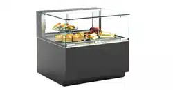
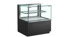
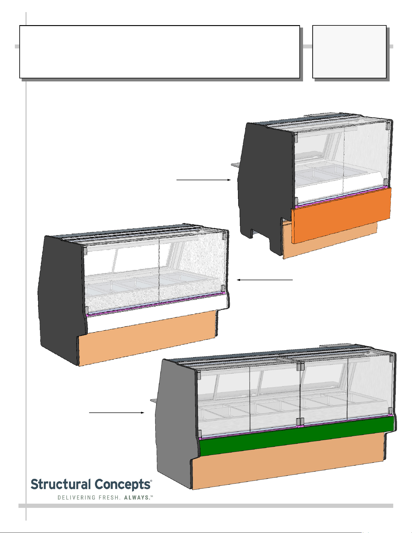
Model GMSV8H
Model GMSV6H
Fusion Model GMSV4H, GMSV6H and GMSV8H and GMSV8H.7215
> Mid-Volume, Angled Back, Vertical Glass, Heated Service Merchandisers
Model GMSV4H
USER
MANUAL
FUSION
READ AND SAVE THESE INSTRUCTIONS
SCC
P/N
20-86531
Structural Concepts Corp. ∙ 888 E. Porter Rd ∙ Muskegon, MI 49441 Phone: 231.798.8888 Fax: 231.798.4960 ∙ www.structuralconcepts.com
2
TABLE OF CONTENTS
OVERVIEW / CONDITION TYPE / TEMP / COMPLIANCE / WARNINGS / PRECAUTIONS /
WIRING ……………………………………………………………....………………………………….
INSTALLATION INSTRUCTIONS ...………………..………………………………...…...………………….
INSTALLATION INSTRUCTIONS, CONT’D: SEALING AND BOLTING HEATED CASES
TOGETHER ……………………………………………………………………………………………..
START-UP / LIGHTING / CASE TEMPERATURE / PROGRAMMABLE CONTROLLERS /
OPERATION ..…………………………………………………………………………………………..
ELECTRICAL CONNECTIONS: ACCESS AND FIELD WIRING ………………………………………...
WELL HEAT ………………………...…………………………………………………………………………..
OVERHEAD CERAMIC HEATERS ..…………………………………………………………………….…...
OVERHEAD CERAMIC METAL HALIDE LIGHT FIXTURES …………………………………………….
HINGED FRONT GLASS DOORS ……………………………….…..………………….…………………...
REAR SLIDING DOORS / REAR LEDGE …………………………………………………………………...
OPTIONAL SCALE STAND ..…………………………………………………………………………………
REMOVING PANS AND DIVIDERS (FOR CLEANING) ....…………………..…………………………….
CLEANING SCHEDULE …………………………………………………………………..…………………...
TROUBLESHOOTING ..………………………………………………………………………………...……...
SERIAL LABEL LOCATION & INFO LISTED / TECH INFO & SERVICE - AMBIENT/HEATED CASE...
PROGRAMMABLE CONTROLLERS (SELECT, CLICK ON OR SCAN QR CODE FOR
INFORMATION) ………………………………………………………………………...……………...
TECHNICAL SERVICE CONTACT INFORMATION & WARRANTY INFORMATION ….…...………...
3-4
5
6
7
8
9
10
11
12
13
14
15
16
17
18
19
20
3
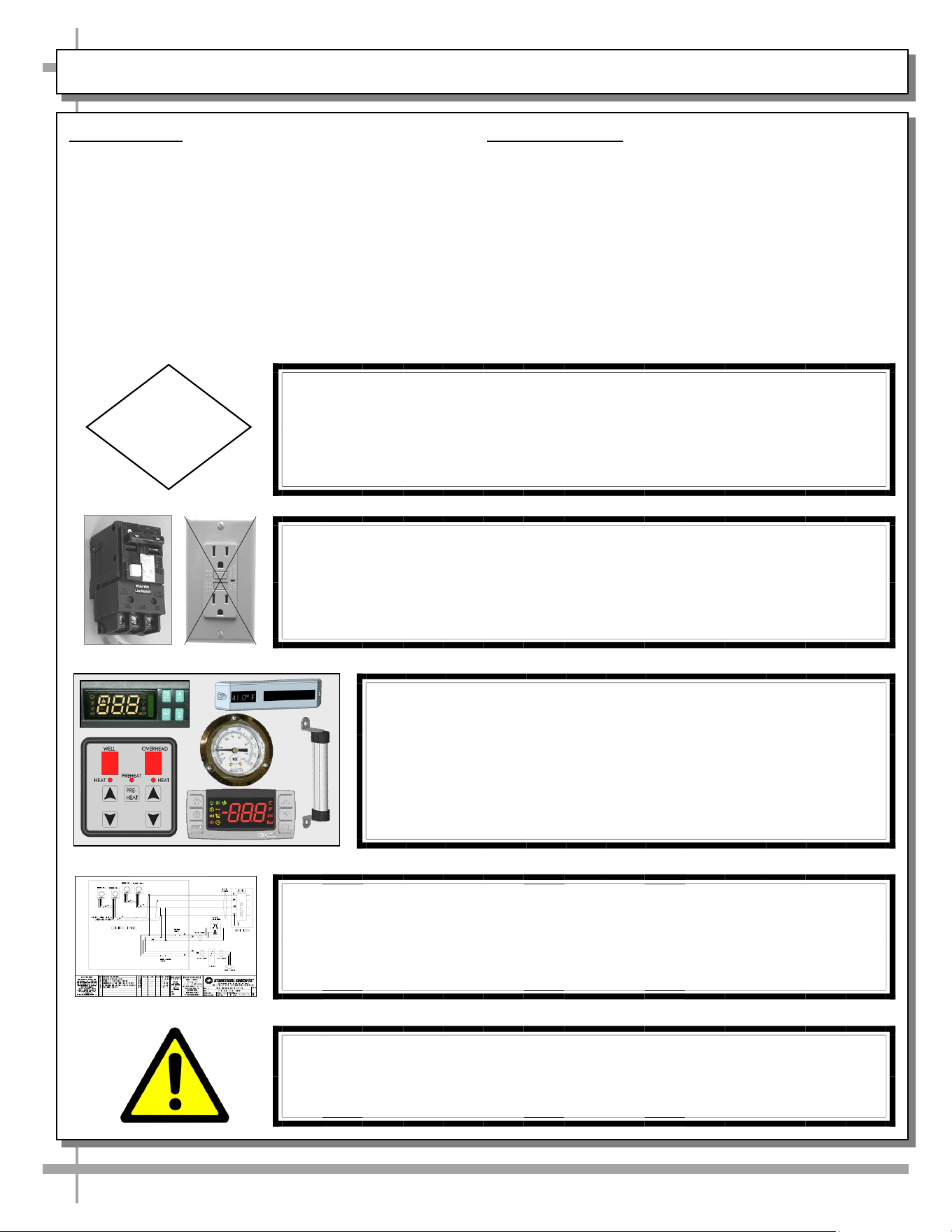
OVERVIEW
This merchandiser is designed for dry heating operations
throughout the product area. The heat is generated from
electric rod well warmers, overhead ceramic heaters and
overhead ceramic metal halide lamps.
• This merchandiser is designed for display of
perishable, unpackaged heated products.
• This merchandiser IS NOT designed to heat products
up; product must be pre-heated PRIOR to its display.
• Cases should be installed and operated according to
this operating manual’s instructions to ensure proper
performance.
• Improper use will void warranty.
NSF/ANSI TYPE I
This unit is designed for the display of products in ambient
store conditions where temperatures and humidity are
maintained within a specific range.
• Ambient conditions are to be at 55% max. humidity
and maximum temperatures of 75 °F (24 °C).
INTEGRATED AVERAGE PRODUCT TEMPERATURE
• The Structural Concepts® Fusion Service Deli
Merchandisers are designed to merchandise product
at an integrated average product temperature of
150 °Fahrenheit / 66 °Celsius.
COMPLIANCE
• Performance issues when in violation of applicable
NEC, federal, state and local electrical and plumbing
codes are not covered by warranty.
• See below compliance guideline.
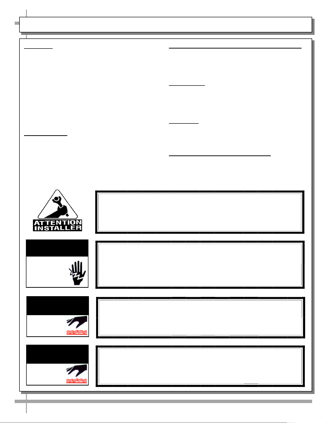
WARNINGS
• This page contains important warnings to prevent
injury or death.
• Please read carefully!
PRECAUTIONS and WIRING DIAGRAMS
• See next page for PRECAUTIONS and WIRING
DIAGRAM information.
WARNING
Ceramic Heaters and Ceramic Metal Halide Lamps Are Hot!
Turn Off or Disconnect and Allow to Cool
Before Servicing or Replacing.
WARNING
HOT
SURFACE
COMPLIANCE
This equipment MUST be installed in compliance with
all applicable NEC, federal, state and local
electrical and plumbing codes.
OVERVIEW / TYPE / TEMP / COMPLIANCE / WARNINGS / PRECAUTIONS / WIRING - PAGE 1 of 2
WARNING
Risk of electric shock. Disconnect power before servicing unit.
CAUTION! More than one source of electrical supply is
employed with units that have separate circuits.
Disconnect ALL ELECTRICAL SOURCES before servicing.
WARNING
ELECTRICAL
HAZARD
WARNING
Pans and Wells Are Hot!
Disconnect and allow to cool
before cleaning or removing from case.
WARNING
HOT
SURFACE
4
CAUTION! LAMP REPLACEMENT GUIDELINES
Allow to cool before accessing lamps.
Lamps are NOT manufactured to resist breakage.
Replace with similarly manufactured lamps of same wattage.
CAUTION
PRECAUTIONS
• Following are important precautions to prevent
damage to unit or merchandise.
• Please read carefully!
• See previous page for specifics on OVERVIEW,
CONDITION TYPE, COMPLIANCE and WARNINGS
.
WIRING DIAGRAM
• Each case has its own wiring diagram folded and in
its own packet.
• Wiring diagram placement may vary; it may be
placed near ballast box, field wiring box, raceway
cover, or other related location.
OVERVIEW / TYPE / TEMP / COMPLIANCE / WARNINGS / PRECAUTIONS / WIRING - PAGE 2 of 2
WIRING DIAGRAM FORMAT & LOCATION
• Each case has its own wiring diagram folded & in its own packet.
• Wiring diagram placement may vary; it may be placed near ballast
box, field wiring box, raceway cover, or other related location.
CAUTION! GFCI BREAKER USE REQUIREMENT
If N.E.C. (National Electric Code) or your local code
requires GFCI (Ground Fault Circuit Interrupter) protection,
you MUST use a GFCI breaker in lieu of a GFCI receptacle.
CAUTION!
DO NOT RELY ON THERMOMETERS OR THERMOSTATS
FOR ACTUAL PRODUCT (FOOD) TEMPERATURES.
• Thermometers & thermostats reflect air temperatures ONLY.
• For ACTUAL product (food) temperatures, use calibrated
probe thermometers.
5
5
WARNING: This product can expose you to chemicals, including
Urethane (Ethyl Carbamate), which are known to the state of
California to cause cancer and birth defects or other reproductive
harm. For more information go to P65Warnings.ca.gov.
5
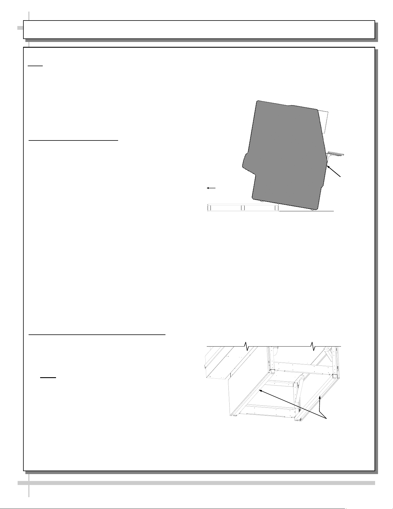
INSTALLATION INSTRUCTIONS
Installation
Note: Units shown may not depict an exact representation of your particular unit being installed.
1. Remove Unit From Skid
Caution: case must always remain supported or
center of gravity will allow case to fall. Slide unit to
rear of skid and tip backward off skid.
Slide
Skid
Out
2. Case Aligning, Adjusting and Sealing
For service glass to align properly, case must be
level and plumb.
• Shims will be provided with all cases that have
frame support rails.
• Note: After case is in position, it must be
sealed to floor to prevent entry or leakage of
liquid or moisture.
• Caution! These units MUST BE sealed to the
floor to maintain conformance to equipment
mounting standards.
• Align multiple units.
Frame
Support
Rails
Support
required
to prevent
tipping.
6
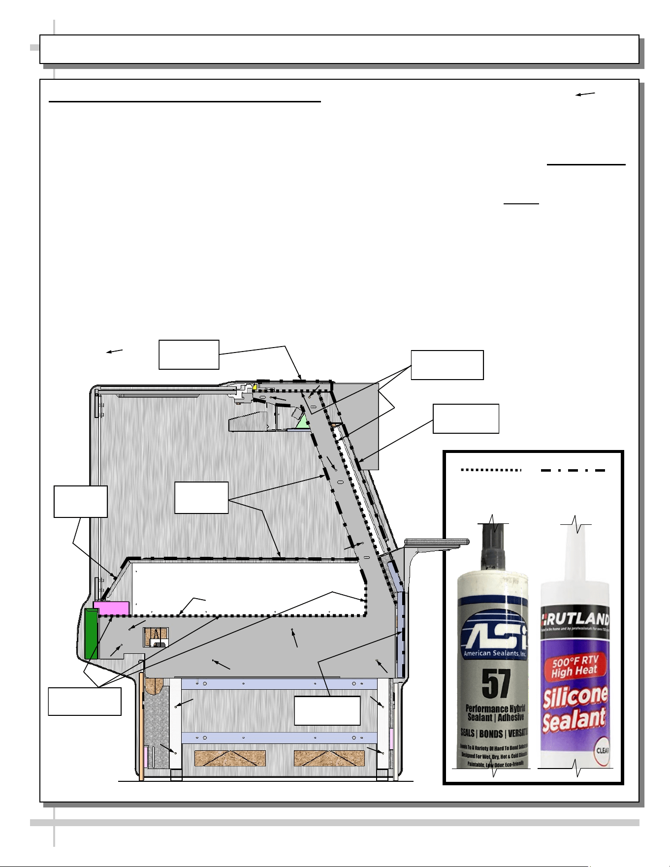
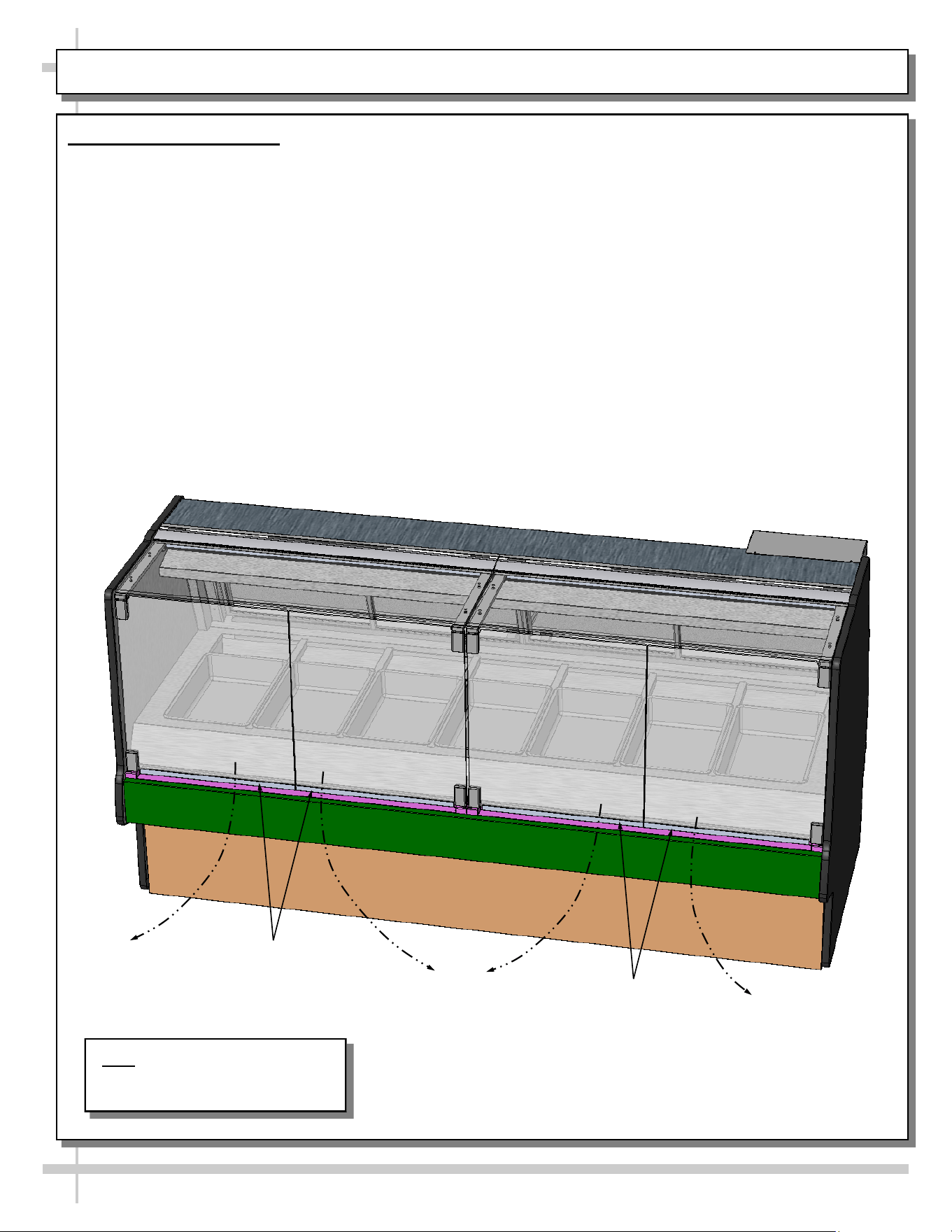
INSTALLATION INSTRUCTIONS, CONT’D: SEALING AND BOLTING HEATED CASES TOGETHER
Sealing and Bolting Heated Cases Together
Follow these steps to assure a secure, level lineup.
A. Begin all lineup leveling from highest point of
floor.
B. After the ’first’ case is level, check that front and/
or rear doors smoothly open and close.
C. Apply a heat-retention bead of industrial grade
urethane adhesive on NON-VISIBLE areas
(at case ends) as directed below. See sample
product at lower-right.
D. Line up ‘second’ case bolt-hole to bolt-hole to
‘first’ case.
E. Using SCC-supplied bolts (found in installation
packet or inserted in holes); connection points are
Deck
Approximate hole
locations pointed at
with arrows ( ) for
bolting units together.
Sanitation
Bead
Heat-Retention
Bead
shown with floating arrowheads below ( ). You
may need to remove decking, side covers, ‘perf’
panel, etc. to access certain holes. Insert bolts.
F. Caution! Front of cases MUST be flush with each
other! After leveling, all cases to be same height.
G. Using SCC-supplied nuts & bolts, lightly tighten
each of the 5 to 8 bolts in a cross-wise pattern.
Work your way around the pattern, tightening
more firmly at each pass. Do not firmly tighten
one bolt and then start on the next!
H. After the cases are bolted together, level the
‘second’ case. Repeat this process for each case
to be adjoined.
I. After all lined-up cases are level, apply a
sanitation bead of industrial grade, heat-rated
silicone sealant as directed below. See sample
product at lower-right.
Heat-Retention
Bead
Urethane For
Heat-Retention
Bead
Heat-Rated
Silicone For
Sanitation Bead
Sanitation
Bead
Sanitation
Bead
Sanitation
Bead
Sanitation
Bead
7
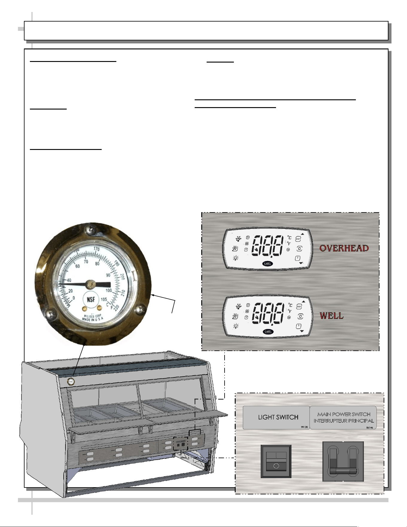
START-UP / LIGHTING / CASE TEMPERATURE / PROGRAMMABLE CONTROLLERS / OPERATION
1. Merchandiser Start-Up
• Case must be field wired.
• When power is supplied, throw main power
switch at case rear-right and case will power-up.
• See illustration below-right.
2. Lighting
• Overhead ceramic metal halide light switch is
at case rear, right side.
• See illustration below-right.
3. Case Temperature
• Well temperature is dependent upon both the
waterless well temperature and the overhead
ceramic heater temperatures.
• Preheat case to 170 °F on case temperature
dial (photo shown below-left) before placing
food into case.
• Caution: Case Temperature dial reflects internal
case temperature ONLY (not product temperature).
Use a food probe to determine ACTUAL product
temperature!
4. Product Heating Guidelines / Programmable
Controllers Information
• Well and overhead ceramic heaters are controlled by
Programmable Controllers.
• These controllers are located on rear wireway cover
(as shown in illustration below-right).
• Programmable controllers are pre-set at the factory to
heat both overhead and well at proper temperatures.
Modifications to these settings should be rare.
• Should programmable controllers need to be revised,
see PROGRAMMABLE CONTROLLER section in
this User Manual for additional information.
Case
Temperature
Dial
Note: Illustration Shown May Not
Exactly Reflect Every Feature or
Option of Your Particular Case.
8
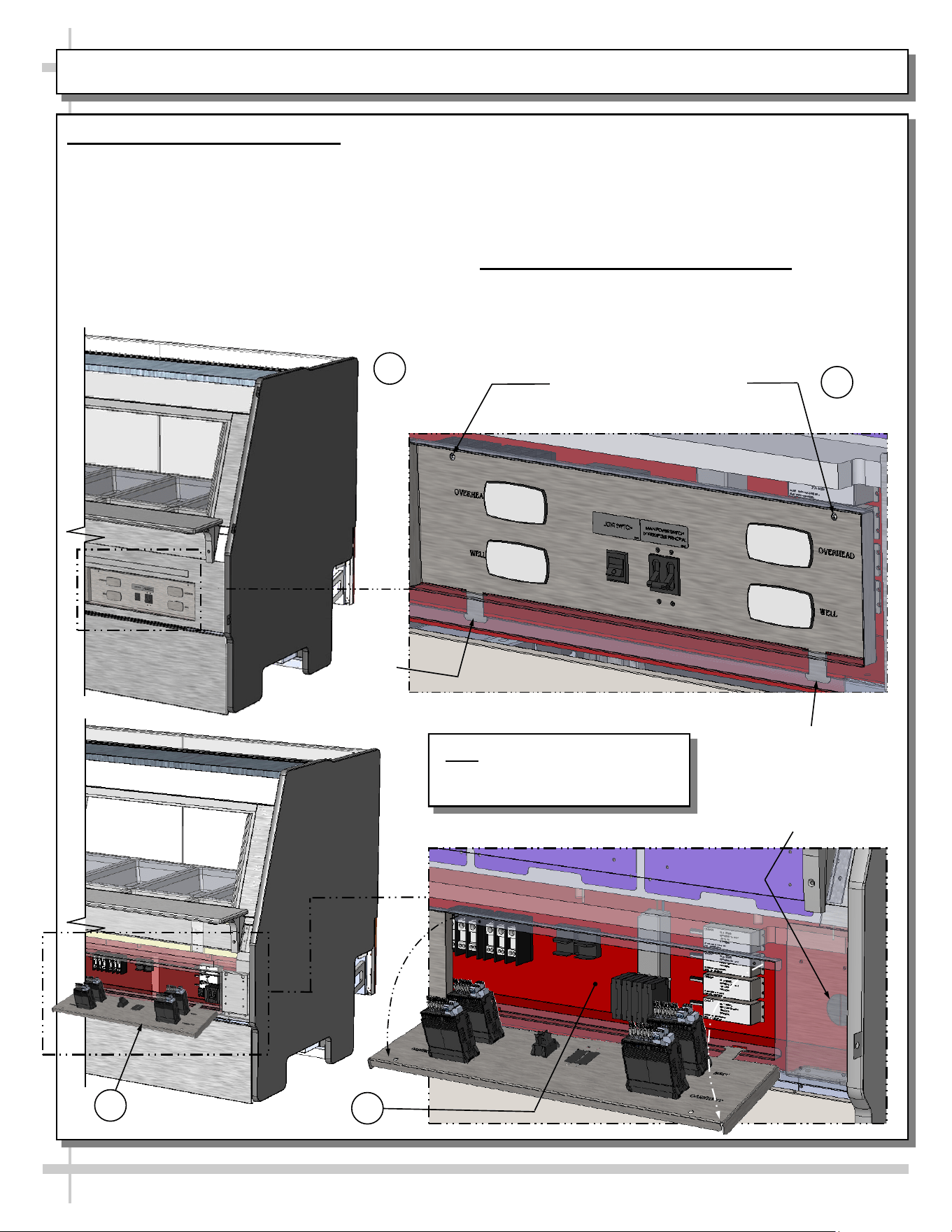
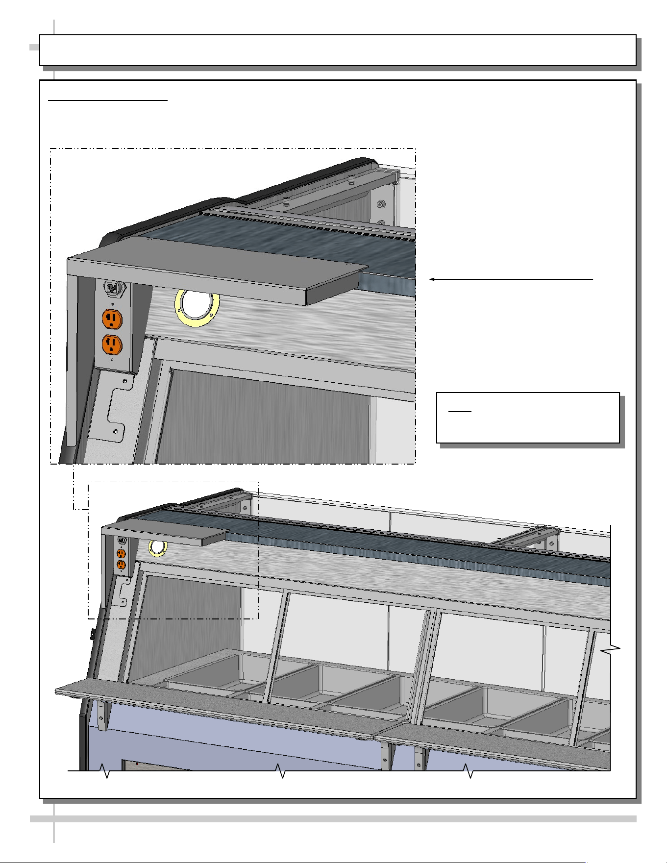
ELECTRICAL CONNECTIONS: ACCESS AND FIELD WIRING
1. Electrical Connections: Access
A. View of case rear. Power to case must be
turned off before accessing rear control panel.
B. Partially transparent view of case showing
screws (to be removed) and tabs.
C. View of rear control panel in lowered position.
D. Enlarged view of rear control panel in lowered
position (as well as field service wiring
knockout). Access is now available to
programmable controllers, terminal strip, ballasts,
terminal block, LED, etc.
> After accessing electrical components (for service or
replacement), return rear control panel to vertical
position and reattach with screws.
2. Electrical Connections: Field Wiring
• Field service wiring knockout is shown in the
lower-right view below.
• See wiring diagram for additional information.
Two (2) Screws To Allow Access
To Electrical Components For
Service or Replacement
A
B
C
D
Field Service
Wiring Knockout
Tab
Tab
factory to heat wells at proper temperatures.
Modifications to these settings should be rare.
• Should programmable controllers need to be
revised, see PROGRAMMABLE CONTROLLER
section in this User Manual for additional
information.
9
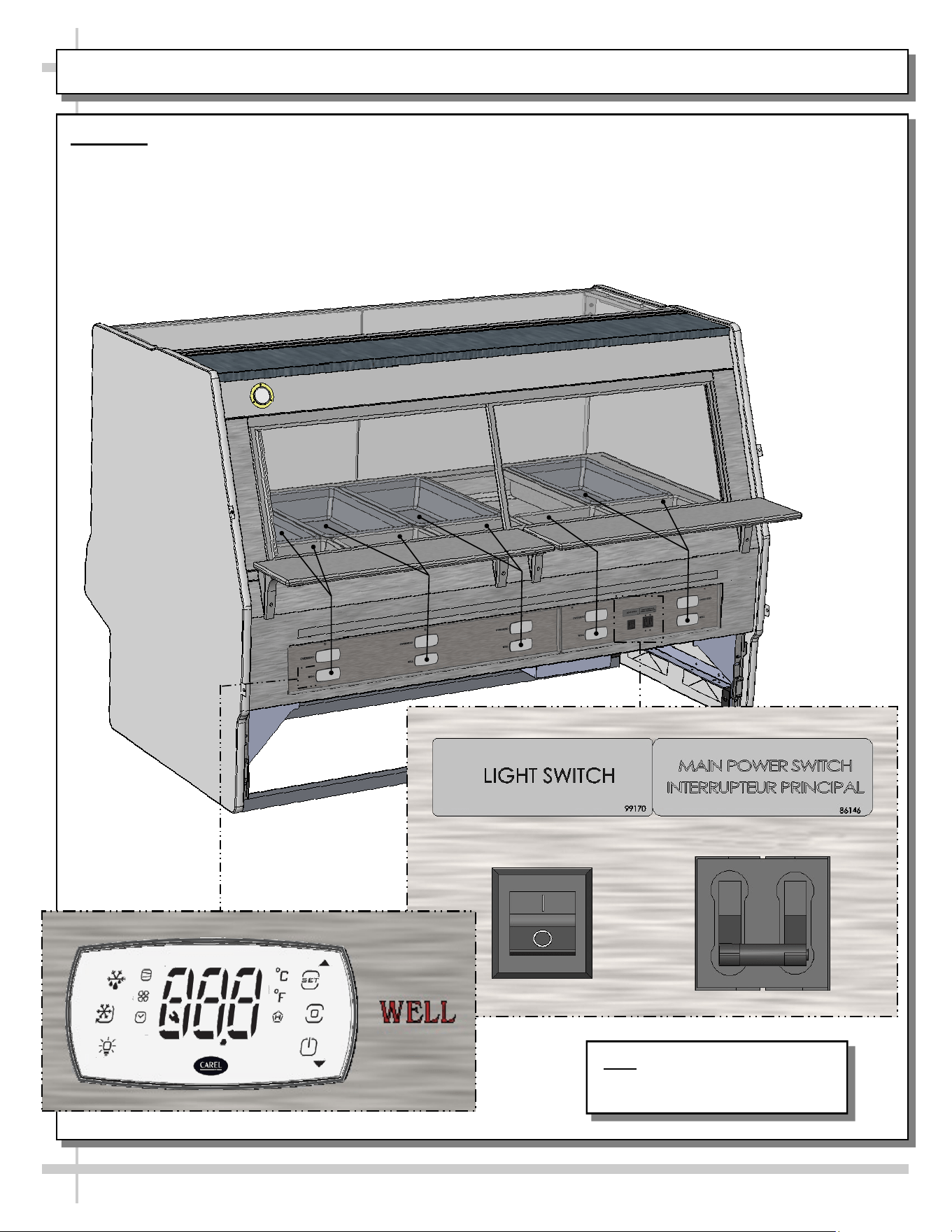
WELL HEAT
Well Heat
• Turn on main power switch.
• Well heat is controlled by Programmable
Controllers.
• Each programmable controller controls the heat
to one set of pans (as illustrated below).
• Programmable controllers are pre-set at the
Note: Illustration Shown May Not
Exactly Reflect Every Feature or
Option of Your Particular Case.
10
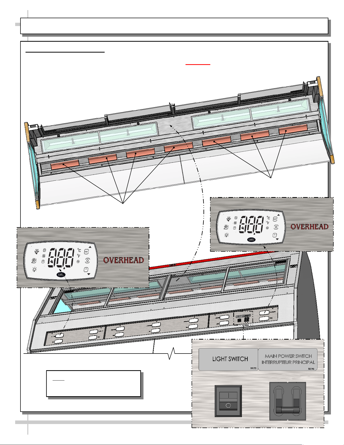
OVERHEAD CERAMIC HEATERS
• See PROGRAMMABLE CONTROLLER section
in this manual for specifics.
• Warning! Disconnect power before providing
maintenance & service to unit.
Overhead Ceramic Heaters
• When main power switch is turned on, overhead
ceramic heaters are energized.
• Each overhead ceramic heater operates
independently of each other.
• Each overhead ceramic heater’s temperature
is controlled by a Carel® iJF Programmable
Controller, located at case rear (as illustrated
below).
Overhead
Ceramic Heaters
Overhead
Ceramic Heaters
Note: Illustration Shown May Not
Exactly Reflect Every Feature or
Option of Your Particular Case.
• As ceramic metal halide lamps may take up to 15
minutes to gain full illumination, turn on lamps
BEFORE loading product into case. This will allow
proper time for proper illumination.
------- ------- ------- ------- -------
• Warning! Disconnect power before providing
maintenance & service to unit. Allow to cool
for at least 15 minutes before accessing.
• After case has been allowed to cool, ceramic
metal halide light fixtures may now be accessed.
• To access light fixtures, unscrew thumbscrews
and lower the light fixture (consisting of metal
housing and glass).
• Then, access lamps for service, removal,
replacement, etc.
11
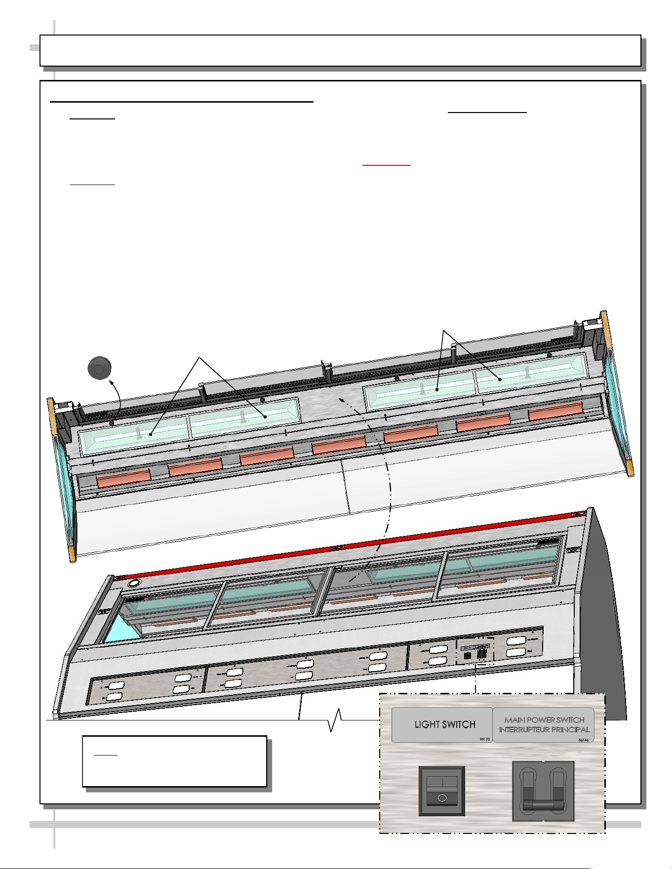
OVERHEAD CERAMIC METAL HALIDE LIGHT FIXTURES
Overhead Ceramic Metal Halide Light Fixtures
• Warning! Lamps are NOT manufactured to
resist breakage. Replace with same wattage
ceramic metal halide lamps (similarly
manufactured). If uncertain of wattage, refer to
label near rear sliding doors for specifics.
• Warning! Ceramic heaters also heat up light
fixtures. So check that entire area has been
allowed to cool before touching light fixtures.
• See illustration below for light switch that
controls overhead ceramic metal halide lights.
• Light switch turns on lights to entire overhead
section of case.
Overhead Ceramic
Metal Halide Lamps
Ceramic Metal
Halide Lamps
Thumbscrew
Note: Illustration Shown May Not
Exactly Reflect Every Feature or
Option of Your Particular Case.
12
HINGED FRONT GLASS DOORS
Hinged Front Glass Doors
• Doors are on side hinges.
• Simply grasp lower handle and pull outward.
• Gently return front glass doors to original position.
• See illustration below.
Note: Illustration Shown May Not
Exactly Reflect Every Feature or
Option of Your Particular Case.
Front
Door
Lower Door
Handles
Front
Door
Front
Doors
Lower Door
Handles
13
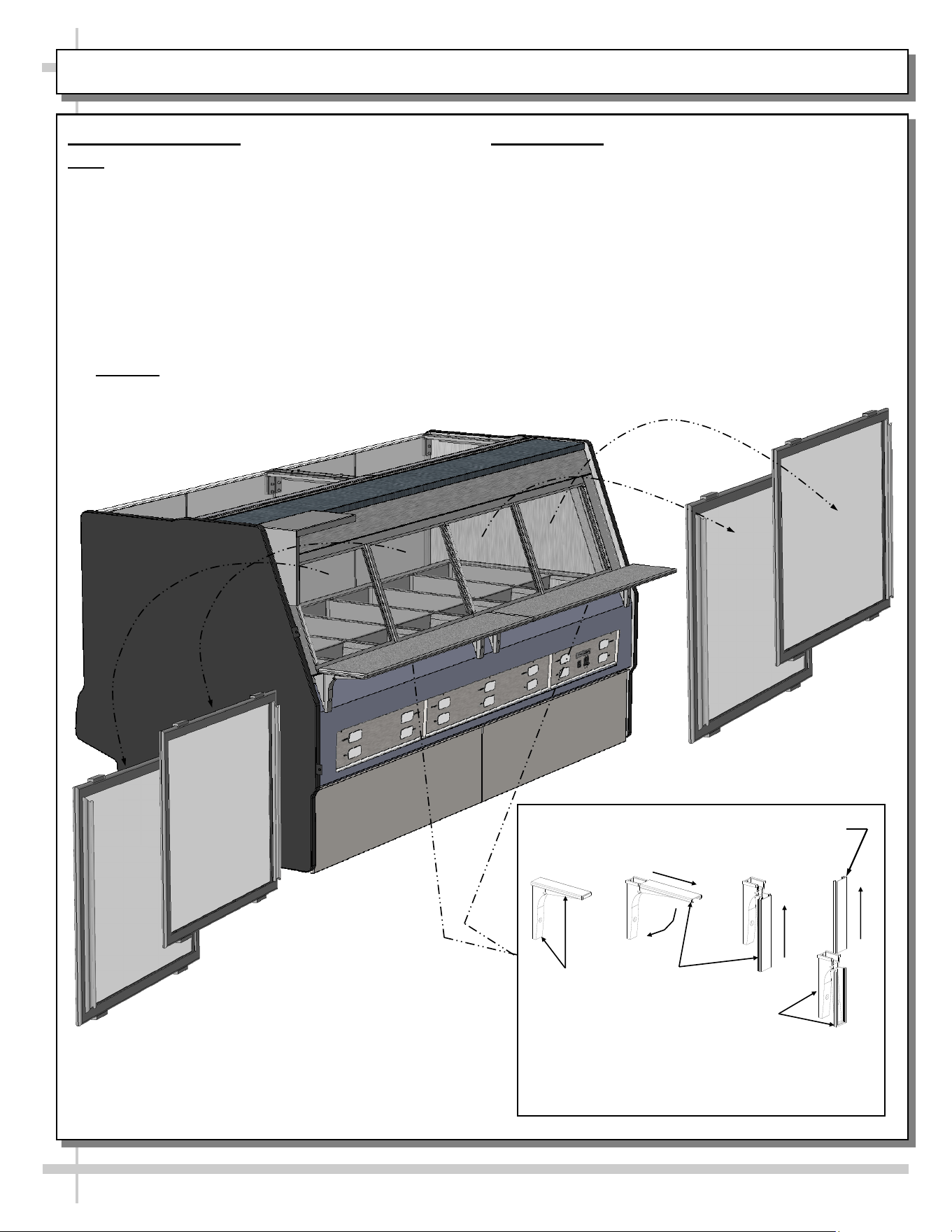
REAR SLIDING DOORS / REAR LEDGE
1. Rear Sliding Doors
Note: Rear sliding doors are not interchangeable.
There is an inner and outer door. The outer door must
be removed first and replaced last.
• The outer door, is the right hand door (from the
service side/rear of case). It can be identified by a
stop located at the lower right hand corner to the
inside of the case.
• Move the doors toward the center of the case.
• Individually lift each door up toward the top of the
case and pivot the bottom of the door out.
• Reverse to reinstall.
• Caution: Gently set doors down to avoid
marring, scraping, scratching or breakage.
Hinged
Support
Bracket
Shelf
Track
Hinged
Support
Bracket
-1- -2- -3- -4-
Shelf Track
—— Rear Ledge Removal Steps ——
Note: For clarity, only Shelf Track is shown being
removed. Rear Ledge is attached to Shelf Track.
2. Rear Ledge
Rear Ledge is connected to shelf track. Illustrations
at right reflect step-by-step removal method (as
enumerated below).
1. Hinged Support Bracket is shown in
its standard upright position.
2 & 3. While upright, Rear Ledge must be
slid away from case and then rotated downward to
vertical position.
3 & 4. From the shelf’s lowered position, lift from
bottom edge upward to disengage shelf track
(and attached Rear Ledge) from bracket.
14
OPTIONAL SCALE STAND
Optional Scale Stand
• Scale stand is provided with receptacle which is to be wired separately.
• Depending upon order, scale stand may be at either left or right of case.
View of Typical Case With
Scale Stand, Receptacle and
CAT-5 Connector
Note: Illustration Shown May Not
Exactly Reflect Every Feature or
Option of Your Particular Case.
15
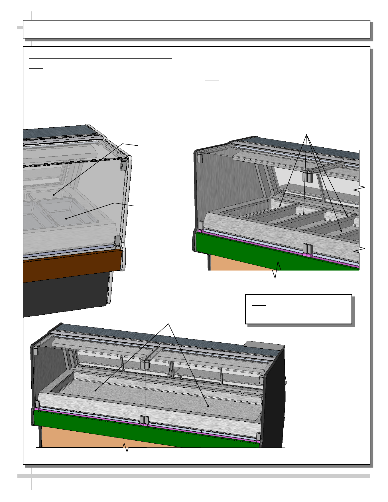
REMOVING PANS AND DIVIDERS (FOR CLEANING)
Removing Pans and Dividers (for Cleaning)
Note: Make certain that unit has been turned off and
allowed to cool before accessing.
1. Remove 1/3rd-Size and Full Size Pans.
2. Remove pan dividers.
3. Perform cleaning service on pan warmer shield.
4. Replace pan dividers and pans in reverse order they
were removed.
> Note: See cleaning schedule for specifics on method
and frequency of cleaning.
2. Remove pan
dividers
Pan (1/3rd
Size) Typ.
Pan (Full
Size) Typ.
1. Remove 1/3rd-Size, Full
Size and/or Drip Pans
3. Perform cleaning
service on pan
warmer shield
4. Replace pan
dividers and pans in
reverse order they
were removed
Note: Illustration Shown May Not
Exactly Reflect Every Feature or
Option of Your Particular Case.
16
CLEANING SCHEDULE
Cleaning Daily Weekly Task
Clean Case Exterior X
Clean side glass, front curved glass and sliding rear doors
(glass) with a household or commercial glass cleaner.
X
Stainless Steel Rear Work Surface:
• Wash with a solution of hand dishwashing liquid detergent and
water; or a solution of baking soda and water. Rinse and
polish dry with paper towel or soft cloth.
• Never use scouring powders or steel wool as they will scratch
stainless steel.
• Brighten by polishing with a cloth dipped in vinegar or in
ammonia; sprinkle baking soda on sponge and rub gently;
rinse. Polish dry with paper towel.
• Remove streaks or heat stains from stainless steel by rubbing
with club soda.
X
Flip-down rear ledge:
• Use a clean cloth with a solution of hand dishwashing liquid
detergent and hot water. Rinse and wipe dry with paper towel
or clean cloth.
Clean Case Interior X
Clean inside surface of front curved glass and glass ends with a
household or commercial glass cleaner.
X
Remove pans (see full size and 1/3rd size pans illustrations in
MAINTENANCE FUNDAMENTALS section of this manual) and
submerse in with warm soap and water solution.
Thoroughly dry before returning to case.
X
• Pan Warmer Shield (surface under removable pans).
• Caution! Turn OFF Main Power Switch. Allow wells to cool
to room temperature before cleaning.
• Clean with mild soap and water solution and a soft cloth.
X
Remove rear doors and clean with a household or commercial
cleaner
Warnings:
1. DO NOT clean heated wells while hot. Flip Well Heater Switches to OFF position. Allow wells to
cool to room temperature before cleaning.
2. Lowering the front glass with items inside top cap can cause damage to case.
3. Lowering the front glass with fingers inside top cap can cause serious injury.
17
TROUBLESHOOTING
Trouble Possible Solution
System is not operating Check that the utility power is on.
Check that the MAIN Power Switch is on.
Check the circuit breaker box for tripped circuits.
Warmers will not heat Check that temperature controllers (at case rear) are at proper
settings.
Warmers slow to heat Check that temperature controllers (at case rear) are at proper
settings.
Case lights not working Check that overhead ceramic metal halide light switch (located at
case rear) is turned on.
Check lamps for proper installation and connection.
• Caution! Ceramic metal halide lamps are extremely hot!
Use caution when accessing!
• Unscrew thumbscrew to remove cover. Caution! Securely hold
lamp cover when removing thumb screw! Both lamp cover and
glass will fall downward when thumbscrew is removed!
Check for burned out bulbs.
Thumb Screw For Lamp
Access (Typical)
Ceramic Metal Halide
Lamps (Typical)
Thumb Screw For Lamp
Access (Typical)
Note: Model Shown Partially
Disassembled For Illustrative
Purposes Only.
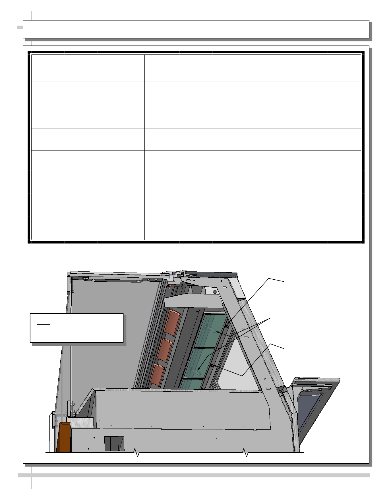
18
SERIAL LABEL LOCATION & INFO LISTED / TECH INFO & SERVICE - AMBIENT/HEATED CASES ONLY
Serial Label Location & Information Listed /
Technical Information & Service
• Serial labels are affixed at a wide range of places
(on the header, at case rear, behind panels or
toe-kicks, on electrical boxes, etc.).
• Serial labels contain electrical information as well
as regulatory standards to which the case
conforms.
• Sample serial label is shown. A variety of models is
displayed on serial label for illustration purposes only.
Your case’s serial label will reflect only one model.
• For additional technical information and service, see
the TECHNICAL SERVICE page in this manual for
instructions on contacting Structural Concepts’
Technical Service Department.
--- Sample Serial Label For Ambient/Heated Cases ---
888 E. Porter Rd - Muskegon, MI 49441
Sample QR Code
SCAN FOR PRODUCT LITERATURE
Reveal
Harmony
Impulse
Addenda
19
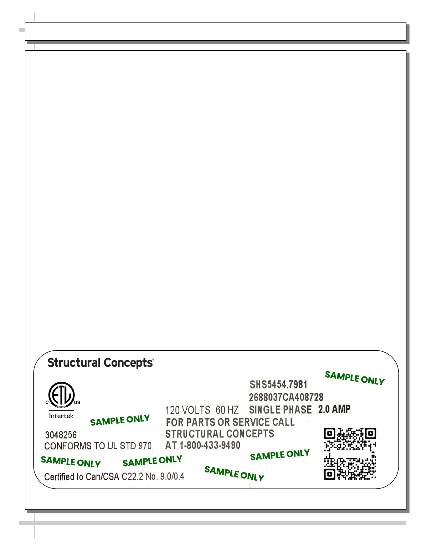
PROGRAMMABLE CONTROLLERS (SELECT, CLICK ON OR SCAN QR CODE FOR INFORMATION)
Carel® iJF Platform
Carel® PJEZ Platform
Carel® ir33 Platform
Dixell® XM670K-XM679K Platform
To Access Information About The Programmable
Controller That Is Used On Your Case,
Follow These Instructions:
> If Viewing This Document on Smart Phone, Tablet
or Computer, Select/Click On The QR Code at Right.
> If Viewing This Document In Print (Hard Copy),
Scan The QR Code at Right With Your Smart Phone
or Tablet.
Determine Which Programmable Controller Is On Your Case (Controllers
That Are Commonly Used By Structural Concepts Are Shown Below).
Your Particular Programmable Controller May Differ From Units Shown.
20
STRUCTURAL CONCEPTS TECHNICAL SERVICE CONTACT INFORMATION & LIMITED WARRANTY
TECH SERVICE/WARRANTY CONTACT INFO:
1 (800) 433-9490 / EXTENSION 1
DAYS/HOURS AVAILABLE:
MONDAY - FRIDAY (CLOSED HOLIDAYS)
8:00 AM to 8:00 PM EST
YOU MUST HAVE THE FOLLOWING INFO AVAILABLE
BEFORE CONTACTING STRUCTURAL CONCEPTS:
SERIAL NO. / MODEL NO. / STORE NO. / STORE
ADDRESS / DETAILS (PHOTOS, LEAK LOCATIONS,
DAMAGE, STORE’S AMBIENT CONDITIONS, ETC.)
To Access The Limited Warranty To Your
Case, Follow These Instructions:
> If Viewing This Document on Smart Phone,
Tablet or Computer, Select/Click On The QR
Code at Right.
> If Viewing This Document In Print (Hard
Copy), Scan The QR Code at Right With Your
Smart Phone or Tablet.