REV E DATE: 06/26/2023
USER MANUALS\21-18041_REVEAL_USER MANUAL_NR(L)(H)HSV_HTD_SVC_FREE-STDG_CASE
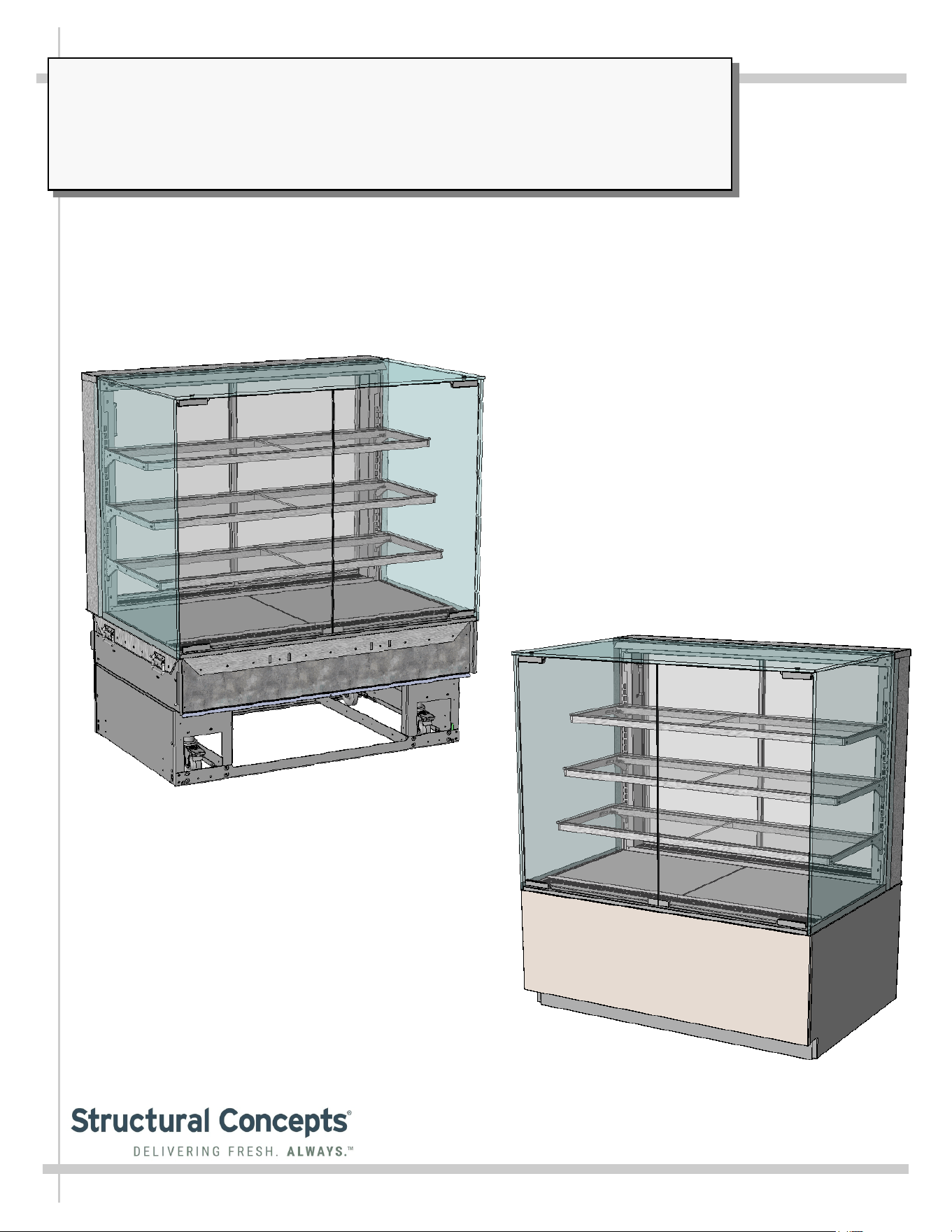
Model NR4855HSV Free Standing Unit
Shown AFTER Front/Side Cladding and
Toe-Kick Have Been Attached
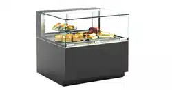
REVEAL® FREE-STANDING HEATED SERVICE MERCHANDISERS
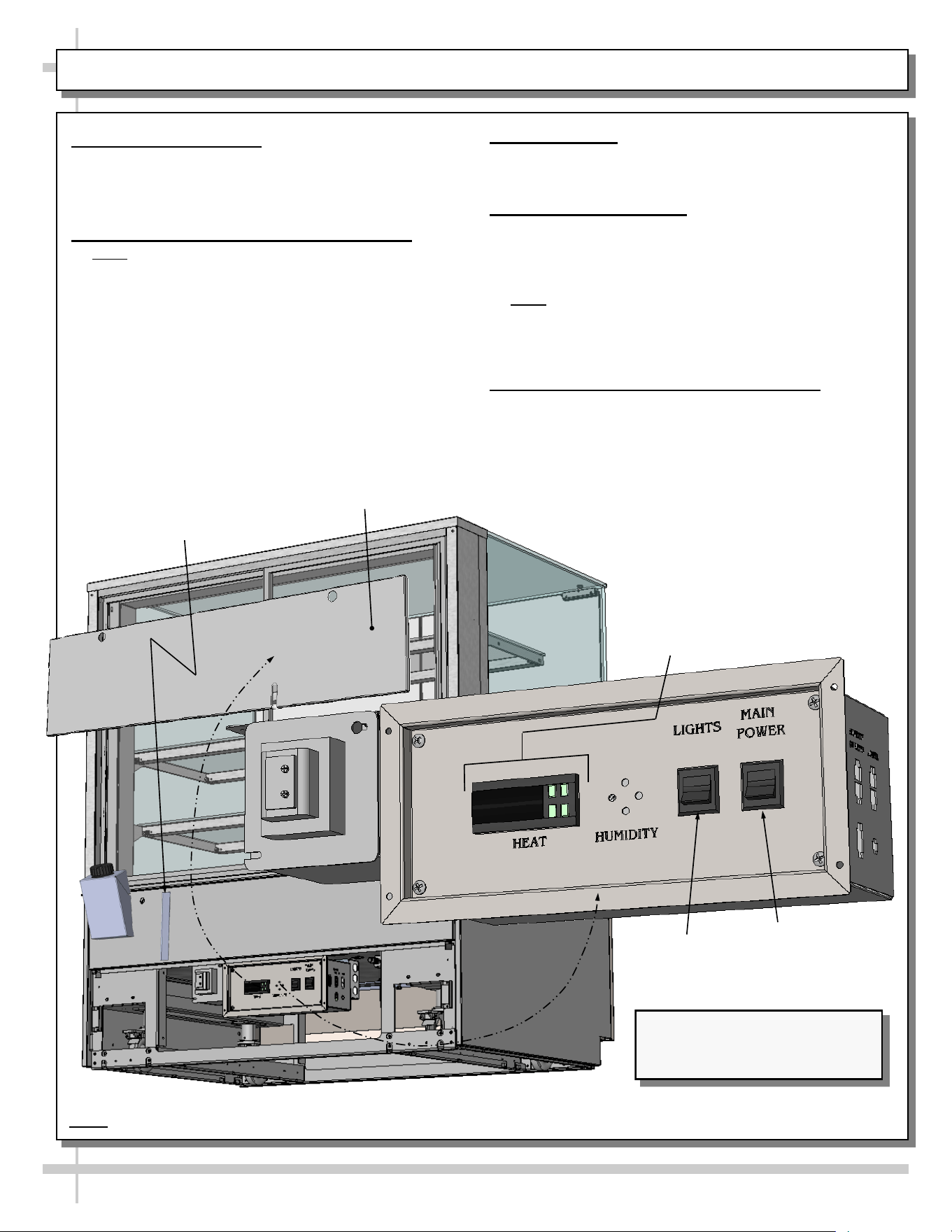
> REAR SLIDING DOORS
> CAUTION! DO NOT PUSH OR PULL ON UPPER GLASS ENCLOSURE!
> ONLY USE HANDLES (AT EACH END OF CASE) TO PUSH OR PULL CASE INTO POSITION!
> SEE PAGES 10-11 FOR PANEL, GRILLE & TOE-KICK ATTACHMENT INSTRUCTIONS
Model NR4855HSV Free Standing Unit Shown
BEFORE Front/Side Cladding and
Toe-Kick Have Been Attached
SCC P/N
20-18041
User
Manual
Reveal
®
READ AND SAVE THESE INSTRUCTIONS
Structural Concepts Corp. ∙ 888 E. Porter Rd ∙ Muskegon, MI 49441 Phone: 231.798.8888 Fax: 231.798.4960 ∙ www.structuralconcepts.com
2
TABLE OF CONTENTS
TABLE OF CONTENTS …………………………………………………………………………………...…...
REVEAL® FREE STANDING HEATED SERVICE MODEL APPLICABILITY & DIMENSIONS ....…..
OVERVIEW / THERMOMETER / COMPLIANCE / WARNINGS / PRECAUTIONS …….……………...
INSTALLATION: TOE-KICK REMOVAL / DISCONNECTING CASE FROM PALLET ...……..……….
INSTALLATION, CONT’D.: CASTER ADJUSTMENT / LOCK / UNLOCK / CASE REMOVAL
FROM PALLET .………………………………………………………………………………...……...
INSTALLATION, CONT’D: SHELVING ASSEMBLY COMPONENTS ...………………………………...
INSTALLATION, CONT’D: PLUG IN UNIT / TURN ON MAIN POWER SWITCH AND LED LIGHT
SWITCH …………………………………………………………….....……………………………..….
INSTALLATION, CONT’D: ATTACHING FRONT PANEL COMPONENTS …………………....……….
INSTALLATION, CONT’D: ATTACHING SIDE PANELS AND REAR PANEL ………………….……..
CASE DESIGN: FRONT VIEW OF FREE STANDING, SERVICE HEATED MERCHANDISERS …...
CASE DESIGN, CONT’D: REAR VIEW OF FREE STANDING, SERVICE HEATED
MERCHANDISERS …………………………………………………………………………………….
CASE DESIGN, CONT’D: CONTROLLER / LED DRIVER / LIGHTS SWITCH / MAIN POWER
SWITCH ……………………...….………………………………………………………………………
CASE DESIGN, CONT’D: TUB ACCESS / HEATER / POWERED HUMIDIFICATION SYSTEM
ACCESS .………………………………………………………………………………………………..
CASE DESIGN, CONT’D: POWERED HUMIDIFICATION SYSTEM / WATER CAPACITY/TYPE ……..
CASE DESIGN, CONT’D: OVERFLOW SYSTEM (FOR POWERED & PASSIVE HUMIDIFICATION
SYSTEMS) ………………………………………………………………………………………….…...
CASE DESIGN, CONT’D: PASSIVE HUMIDIFICATION SYSTEM / HUMIDITY CONTROL LEVER
AND ADJUSTMENT LEVER KEY ….…………………………………………………………………
CASE DESIGN, CONT’D: LED LIGHT CONNECTION / THERMOMETER FUNCTION &
PLACEMENT ………………………………………………………………………….………….....….
CASE DESIGN, CONT’D: REAR SLIDING DOOR REMOVAL & REPLACEMENT ………...…………
CASE STARTUP / HEATER SETTINGS / LIGHTS SWITCH / SHUTDOWN / PASSIVE
HUMIDIFICATION SYSTEM (OPTIONAL) LEVER KEY STORAGE ..…………………………..
PRODUCT PLACEMENT / AIRFLOW CONSIDERATION / LOAD LINES ………………………….…..
CLEANING SCHEDULE (TO BE PERFORMED BY STORE PERSONNEL) ..…....…...…………...….
PREVENTIVE MAINTENANCE (TO BE PERFORMED BY TRAINED SERVICE PROVIDER) ……....
TROUBLESHOOTING (TO BE PERFORMED BY STORE PERSONNEL ONLY) ...………………......
TROUBLESHOOTING (TO BE PERFORMED BY TRAINED SERVICE PROVIDERS ONLY) ……….
SERIAL LABEL INFORMATION & LOCATION ..…………………………….……...…....……………..…
PROGRAMMABLE CONTROLLER INFORMATION .………………….………………………………….
TECHNICAL SERVICE CONTACT INFORMATION / WARRANTY INFORMATION ...…...…...….....
2
3
4-5
6
7
8
9
10
11
12
13
14
15
16
17
18
19
20
21
22
23
24
25-26
27-28
29
30
31
3
REVEAL® FREE STANDING HEATED SERVICE MODEL APPLICABILITY & DIMENSIONS
Model
Upper Display
Height
Overall Height Case Depth x Length
NR3633HSV 13 5/8”UDH 32 7/8”OH 33”D x 35 3/4”L
NR3640HSV 20 3/8”UDH 39 5/8”OH 33”D x 35 3/4”L
NR3647HSV 27 7/8”UDH 47 1/8”OH 33”D x 35 3/4”L
NR3655HSV 35 1/4”UDH 54 5/8”OH 33”D x 35 3/4”L
NR4833HSV 13 5/8”UDH 32 7/8”OH 33”D x 47 3/4”L
NR4840HSV 20 3/8”UDH 39 5/8” 33”D x 47 3/4”L
NR4847HSV 27 7/8”UDH 47 1/8”OH 33”D x 47 3/4”L
NR4855HSV 35 1/4”UDH 54 5/8”OH 33”D x 47 3/4”L
4
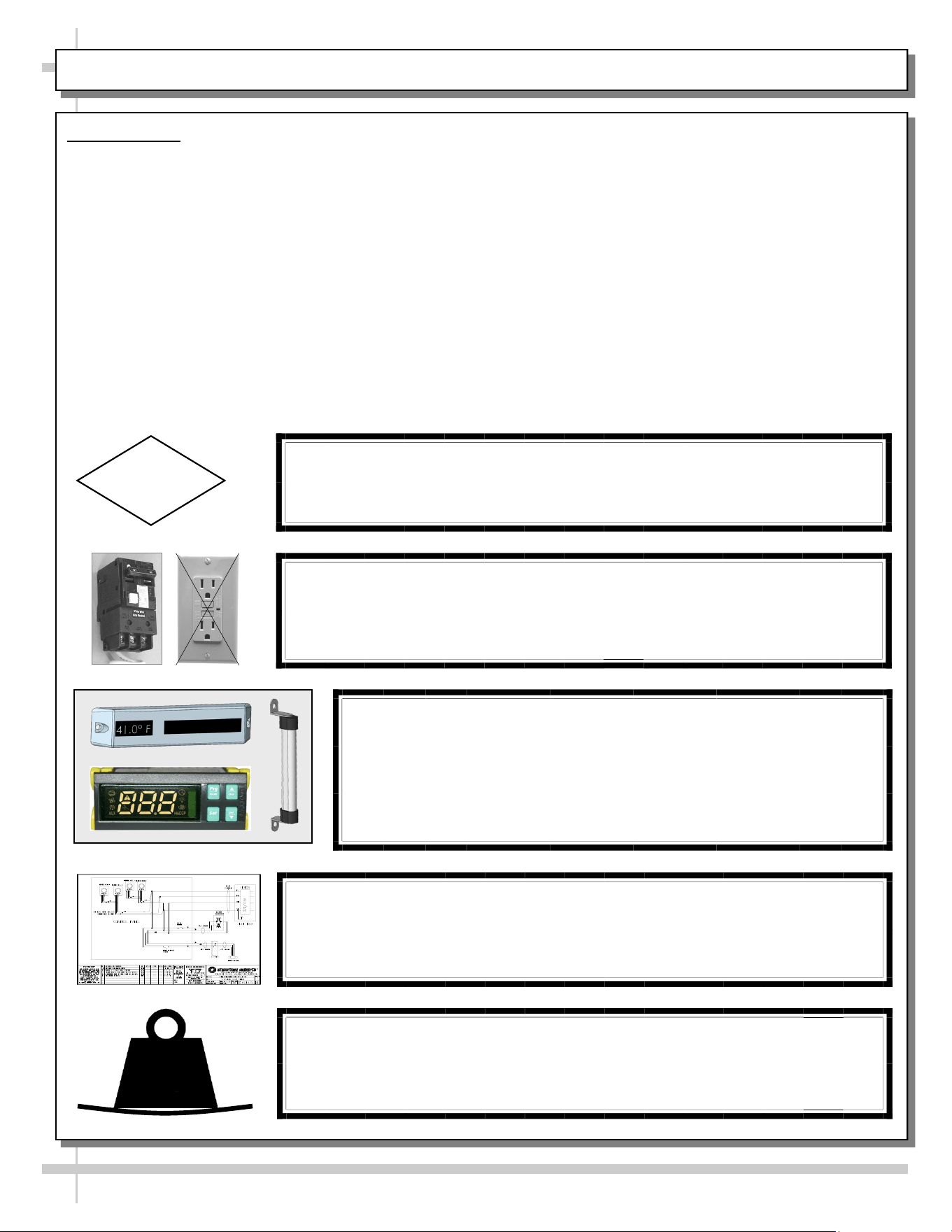
OVERVIEW / THERMOMETER / COMPLIANCE / WARNINGS / PRECAUTIONS - PAGE 1 of 2
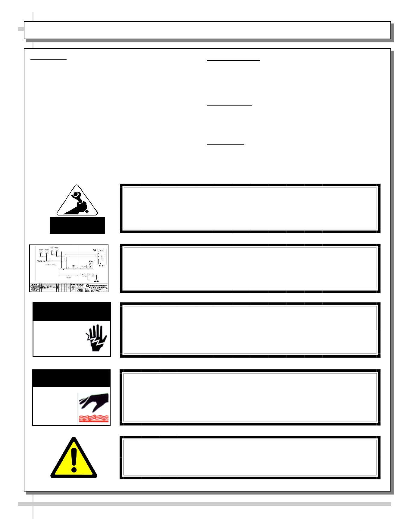
WARNING
Risk of electric shock. Disconnect power before servicing unit.
CAUTION! More than one source of electrical supply may be
employed with units that have separate circuits.
Disconnect ALL ELECTRICAL SOURCES before servicing.
WARNING
ELECTRICAL
HAZARD
OVERVIEW
• These Structural Concepts Reveal® heated cases
are designed to hold pre-heated, perishable,
packaged foods at 140 °F to 180 °F (60 °C to 82 °C).
• Cases should be installed and operated according to
this operating manual’s instructions to insure proper
performance. Improper use will void warranty.
• Product must be pre-heated before placing in
merchandiser. This case is NOT designed to heat
product from cold or ambient condition.
• All heating elements are thermostat controlled for
individual adjustment.
COMPLIANCE
This equipment MUST be installed in compliance with
all applicable NEC, federal, state and local
electrical and plumbing codes.
THERMOMETER
• Thermometers in equipment reflect internal air
temperature only (not actual food temperature).
• Use probe thermometers to determine actual product
temperatures.
COMPLIANCE
• Performance issues when in violation of applicable
NEC, federal, state and local electrical and plumbing
codes are not covered by warranty. See below.
WARNINGS
• Please read the important warnings in this document
carefully as they can prevent injury or death.
• See next page for PRECAUTIONS.
ATTENTION
CONTRACTORS
WARNING: This product can expose you to chemicals, including
Urethane (Ethyl Carbamate), which are known to the state of
California to cause cancer and birth defects or other reproductive
harm. For more information go to P65Warnings.ca.gov.
WARNING
Decks and shelves may be hot! Disconnect and allow to cool
before cleaning or removing from case.
WARNING
HOT
SURFACE
WIRING DIAGRAM FORMAT & LOCATION
• Each case has its own wiring diagram folded & in its own packet.
• Wiring diagram placement may vary; it may be placed near field
wiring box, raceway, or other related location.
5
OVERVIEW / THERMOMETER / COMPLIANCE / WARNINGS / PRECAUTIONS - PAGE 2 of 2
PRECAUTIONS
• Following are important precautions to prevent damage to unit or merchandise.
• Please read carefully!
CAUTION! LAMP REPLACEMENT GUIDELINES
LED lamps reflect specific size, shape and overall design.
Any replacements must meet factory specifications.
CAUTION
WIRING DIAGRAM FORMAT & LOCATION
• Each case has its own wiring diagram folded & in its own packet.
• Wiring diagram placement may vary; it may be placed near field
wiring box, raceway, or other related location.
CAUTION!
DO NOT RELY ON THERMOMETERS OR THERMOSTATS
FOR ACTUAL PRODUCT (FOOD) TEMPERATURES.
• Thermometers and thermostats reflect air temperatures ONLY.
• For PRECISE food temperatures, use calibrated food
thermometers ONLY.
CAUTION! GFCI BREAKER USE REQUIREMENT
If N.E.C. (National Electric Code) or your local code
requires GFCI (Ground Fault Circuit Interrupter) protection,
you MUST use a GFCI breaker in lieu of a GFCI receptacle.
CAUTION!
• To prevent sagging or breakage, do not exceed 5 LBS (2.3 KG)
weight load per top glass section (between vertical supports).
• To prevent scratching or marring, do not place ANY items on glass.
5
LBS
6
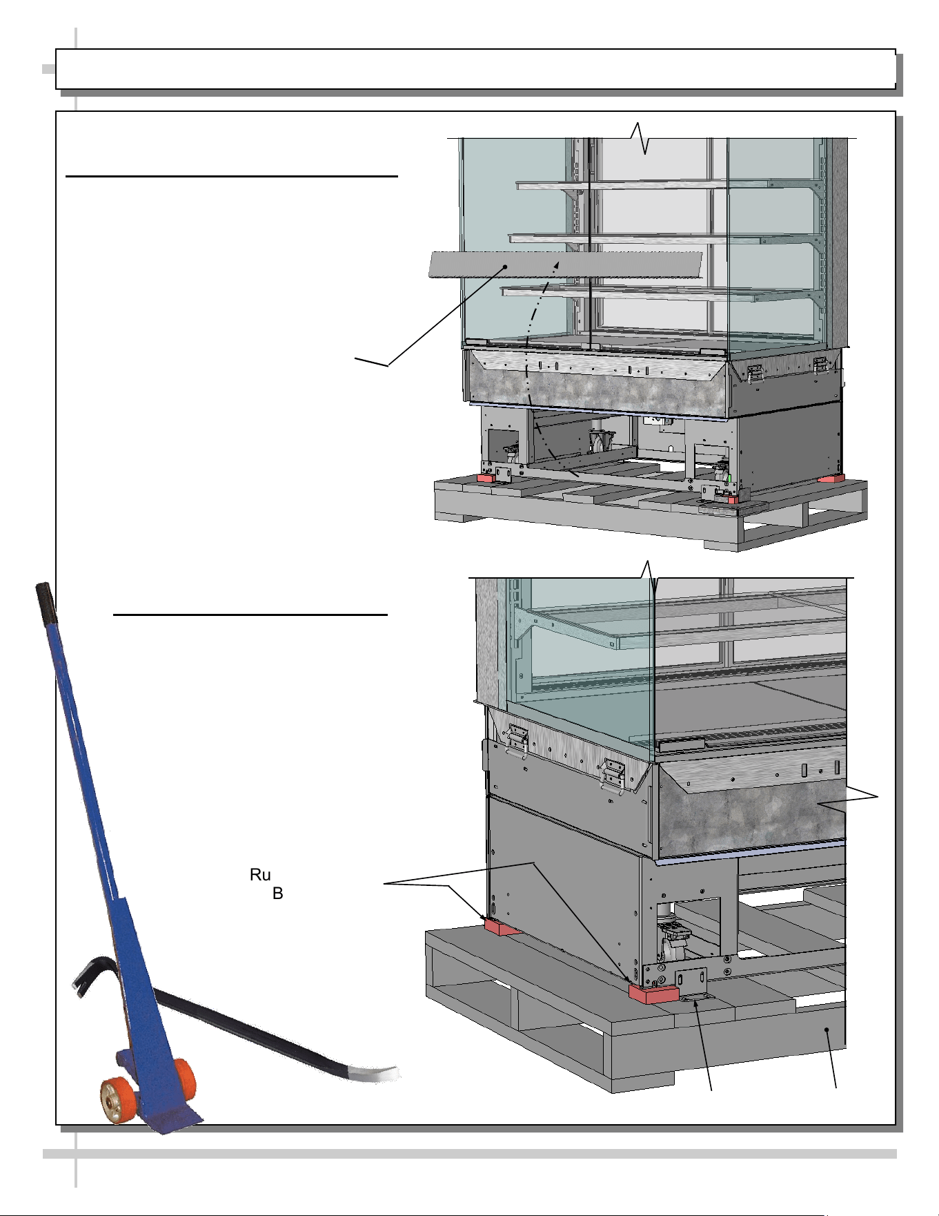
INSTALLATION: TOE-KICK REMOVAL / DISCONNECTING CASE FROM PALLET
Pallet
Rubber Shipping
Blocks, (Typ.)
Shipping Bracket
1. Remove Front Toe-Kick From Case
• To prevent damage to case, remove front
toe-kick from case before removing from
pallet.
• Toe-kick is held in place by magnets only.
No screw removal is required.
• Place front toe-kick in secure location
while removing case from pallet.
Front Toe-Kick
2. Disconnect Case From Pallet
• Remove screws from shipping brackets.
Remove and discard shipping brackets
from pallet.
• Place J-bar/pry under base frame.
Raise case up from pallet to take weight
off casters.
• With case raised, lower casters all the
way down against pallet (see next step
for detailed instructions on lowering or
raising casters).
• Remove rubber shipping blocks.
7
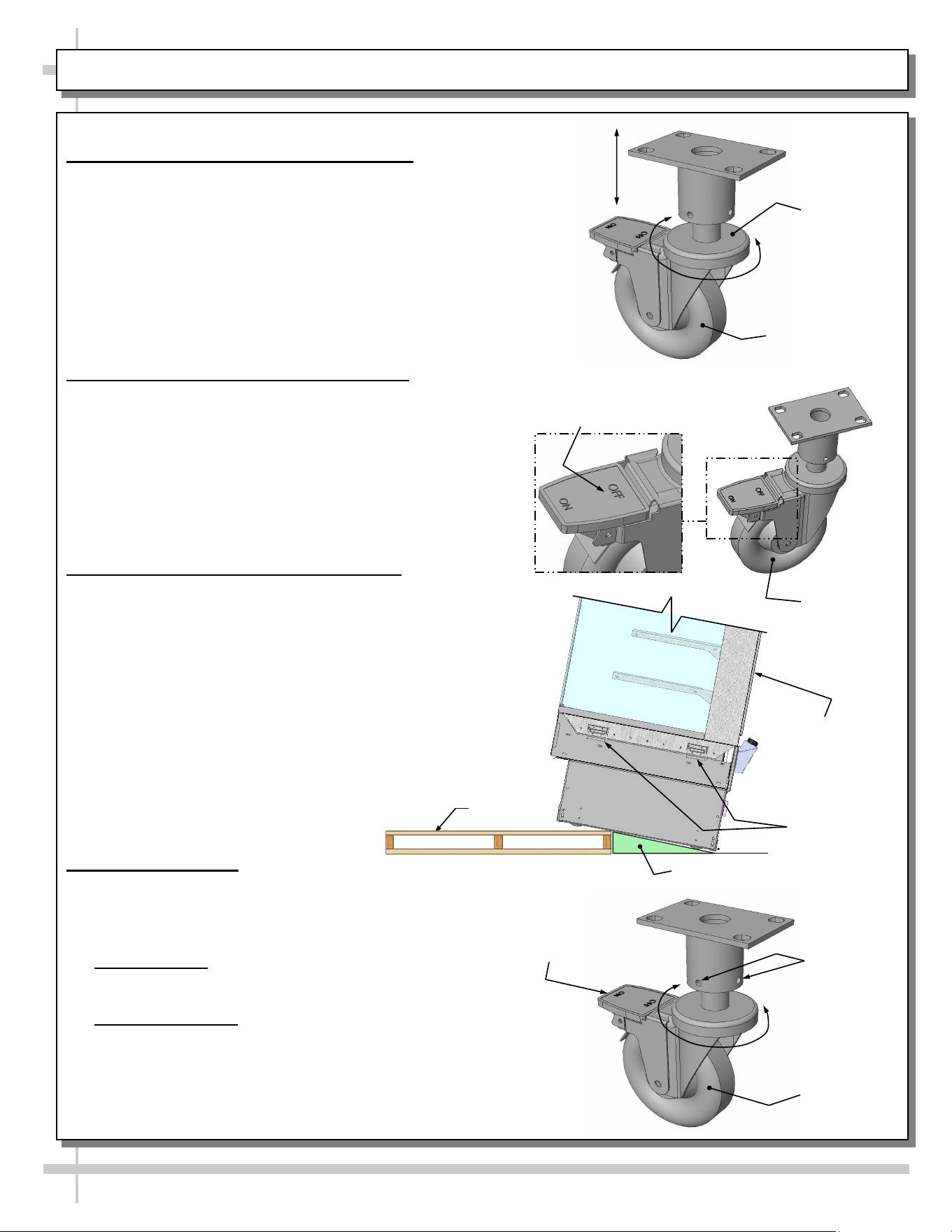
INSTALLATION, CONT’D.: CASTER ADJUSTMENT / LOCK / UNLOCK / CASE REMOVAL FROM PALLET
3. Caster Height: Raising and Lowering
• Raise or lower casters (to adjust case height) by
rotating casters’ vertical adjustment rings.
• Rotate vertical adjustment ring clockwise to lower
caster (and increase height of case).
• Rotate vertical adjustment ring counter-clockwise
to raise caster (and decrease height of case).
4. Caster Rolling Capability: Unlocking
• Important! Case is shipped with caster mechanisms
factory set at ON (locked) to prevent case from
rolling.
• Unlock casters by pressing OFF on the caster
mechanism.
• See illustration at right.
5. Carefully Remove Case From Pallet
• Check that casters are lowered as far down as they
will go (as instructed in step #4).
• Use handles to carefully slide case to rear of pallet
(see illustration at right).
• Caution! 4 people are required for this task!
• Carefully lower to floor (using ramp if available).
• Slide pallet from under case as required.
• Maintain support of case at all times or center
of gravity may cause case to fall.
• See illustration at right.
6. Casters: Locking
• After case is at desired position (and height),
use level to check that case is level and plumb.
• Readjust height as needed (as instructed in
step #4).
• Locking Height: After proper height (and
positioning) of case is attained, tighten the two (2) set
screws to lock each caster’s height in place.
• Locking Movement: Then, to prevent casters’ rolling
capability, lock casters by pressing ON atop the “ON”
and “OFF” lever mechanism (shown at right). Case
will now be secured at its new location.
Vertical
Adjustment
Ring
Caster
Caster
Tighten Set
Screws To
Lock Caster
Height In
Place
Press “ON” Lever To
Lock Caster In Place
(And Prevent Casters’
Rolling Capability)
Pallet
Support case
while removing
from pallet
Press “OFF” Lever To
Unlock Casters (And
Allow Casters To Roll)
Caster
Handles
Ramp
8
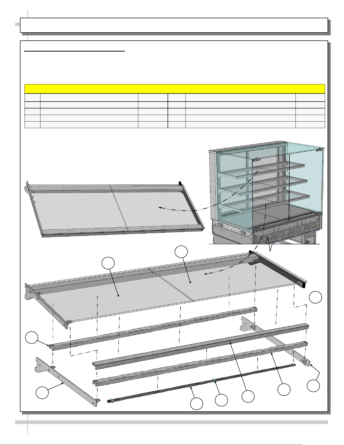
INSTALLATION, CONT’D: SHELVING ASSEMBLY COMPONENTS
7. Shelf Assembly Components
• Check that glass shelving is in proper position before
placing product in case
• Shelves may be adjusted vertically or entirely removed
from merchandiser.
5
7
8
6
• Metal shelving brackets ARE NOT able to be angled.
They are at a fixed 90° position.
• These components comprise EACH shelf assembly.
SHELF ASSEMBLY COMPONENTS
P/N COMPONENT NAME AMOUNT P/N COMPONENT NAME AMOUNT
1 GLASS, LEFT HAND* 1 5 BRACKET, RIGHT HAND 1
2 GLASS, RIGHT HAND* 1 6 LIGHT, LED 1
3 REAR/FRONT SHELF SUPPORT RAIL 2 7 CLIP, LED 2-3*
4 BRACKET, LEFT HAND 1 8 FRONT COVER~ 1
3
*Assembled with rear cover (to rest on rear support rail) before leaving factory.
**Number of LED clips depends upon case length.
~To rest on front shelf support rail.
1
4
Fully Assembled Shelf Assembly
(For Illustrative Purposes Only)
4
2
3
9
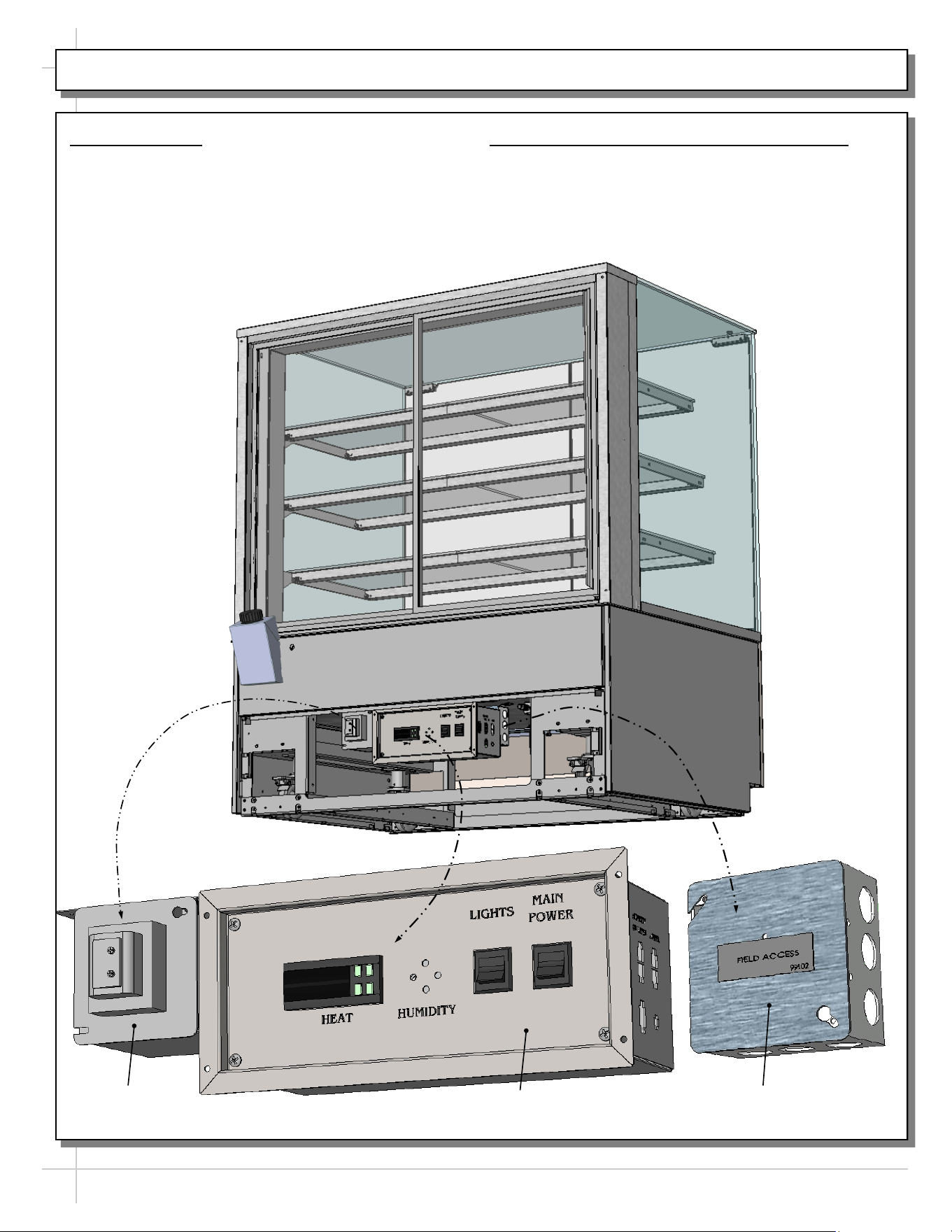
INSTALLATION, CONT’D: PLUG IN UNIT / TURN ON MAIN POWER SWITCH AND LED LIGHT SWITCH
8. Plug Case In
• Check field access box for factory-supplied
power cord.
• Plug case into electrical outlet.
• See enlarged illustration below-right.
9. Main Power Switch / LED Light Switch
• Main power switch and LED lights switch is
accessible at case rear electrical box.
• Turn on main power switch and LED lights
switch.
• See partially-disassembled illustration below.
Transformer
Electrical Box
Field Access Box
Note: Illustration shown may
not reflect every feature or
option of your particular case.
10
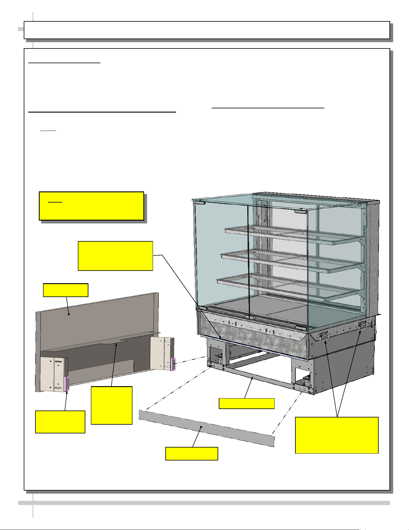
INSTALLATION, CONT’D: ATTACHING FRONT PANEL COMPONENTS
10. Shipping Brace
• Shipping brace keeps case secure during
shipment as well as during positioning in store.
• After case is in position, shipping brace may be
removed from case front (though not required).
11. Attaching Front Panel Components
• Carefully remove components from packaging.
• Note: All front panel components may be attached
to case via magnets (WITHOUT screw
attachments).
• Attach front toe-kick to case (via lower magnets).
• Slide front panel horizontal support bracket into
case’s support slot (line up arrows).
• Then, slide front panel into case until it attaches
to case via lower magnets.
• See illustration below.
12. Handles On Sides of Case
• Handles may remain on case after it has been
moved into position and cladding is attached.
• However, if handles interfere with the placement
of cladding, they may be removed.
>> See Next Page For Instructions on ATTACHING
SIDE PANELS, REAR PANEL AND GRILLE.
Support Slot (For Front
Panel’s Horizontal
Support Bracket)
Shipping Brace
Front Toe-Kick
Front Panel
Horizontal
Support
Bracket
Front Panel
Magnet (Typ.)
Front Panel
Handles (on Both Sides
of Case) May Be
Removed If They Interfere
With Cladding.
11
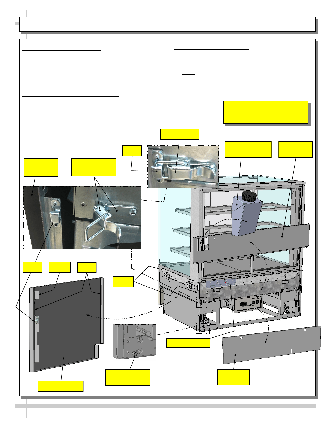
INSTALLATION, CONT’D: ATTACHING SIDE PANELS AND REAR PANELS
13. Attaching Side Panels
• Attach side panels to case using slot/hook
method.
• Use latches at case rear to firmly attach side
panels to case.
• See illustrations below.
14. Attaching Rear Upper Panel
• Place rear upper panel onto care rear.
• Four (4) magnets will hold it firmly in place.
• See illustration below
15. Attaching Rear Grille
• Use finger holes to place rear grille onto lower
rear of case. Magnets will hold it firmly in place.
>> Note: Components may be removed in reverse
order they were shown being attached on this sheet.
Hook
Unlocked Latch
(Typ.)
Side Panel (Typ.)
Rear Upper
Panel
Slots
Side Panel
(Typ.)
Insert
Hooks
Locked Latch
Hook
Shoulder Screw
(Typ.)
Note: Illustration shown may
not reflect every feature or
option of your particular case.
Rear Lower
Panel
Water Fill Funnel
(Optional)
Funnel Bracket
12
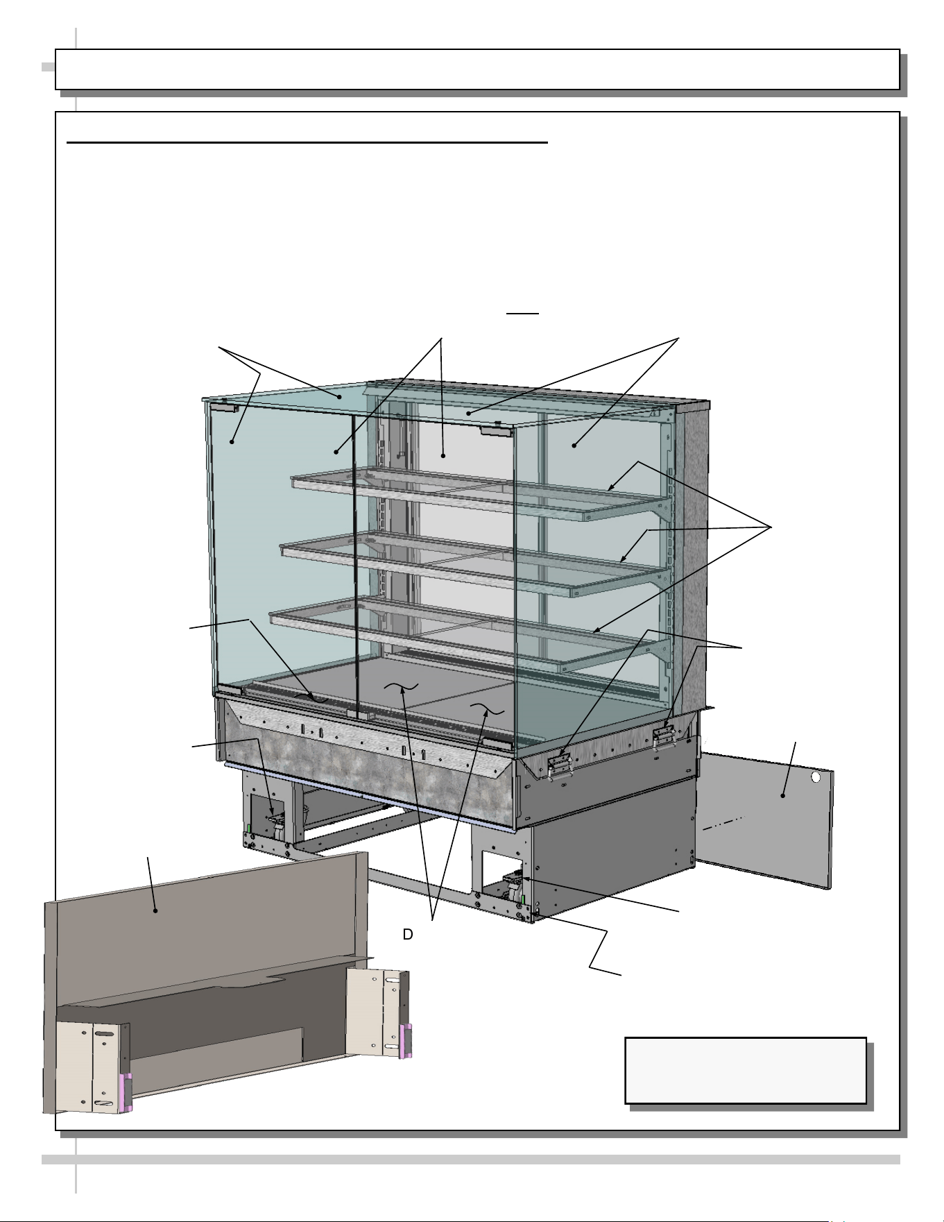
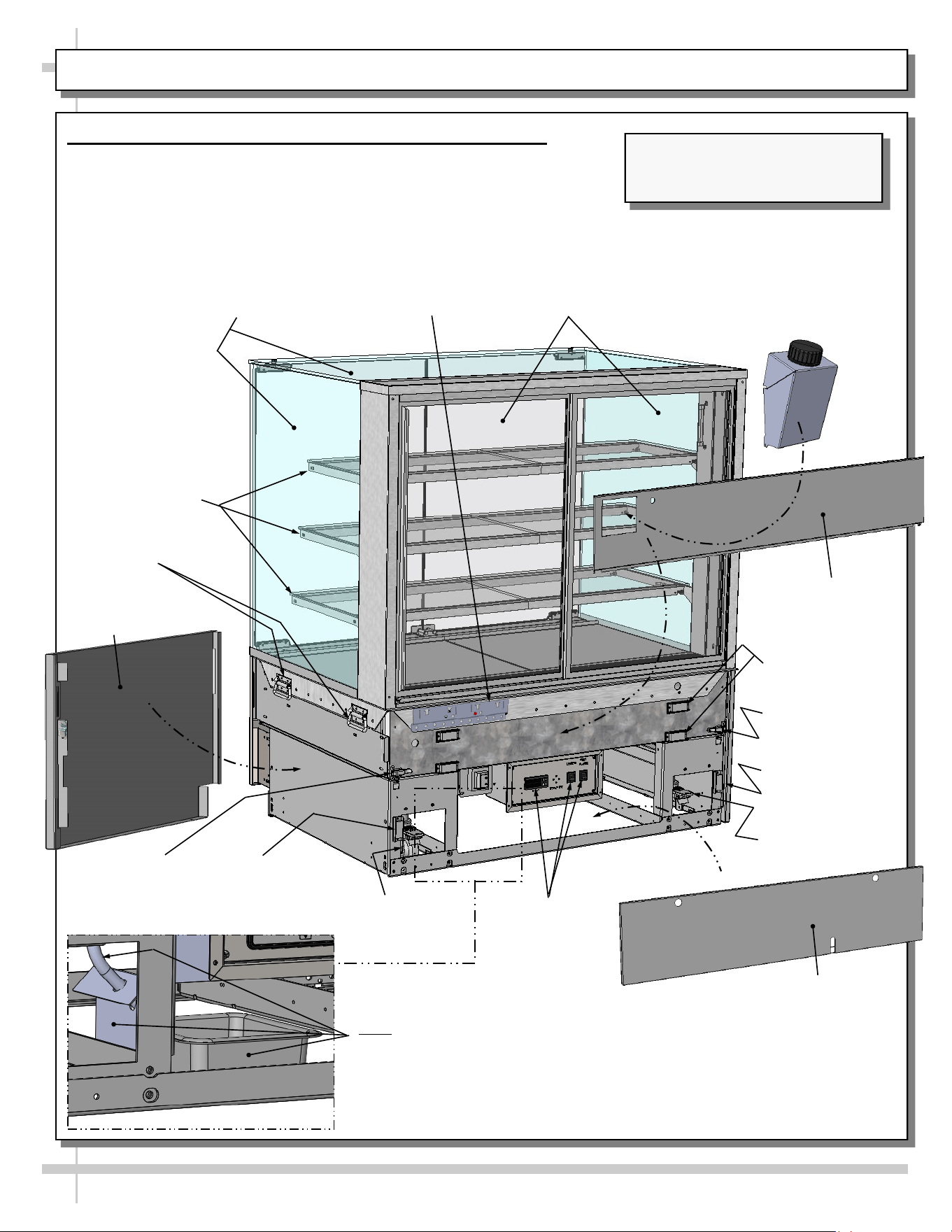
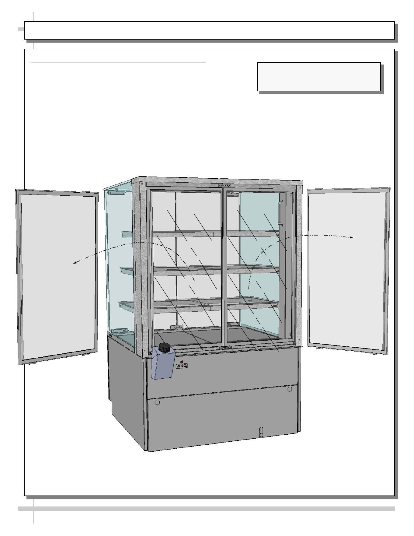
CASE DESIGN: FRONT VIEW OF FREE STANDING, SERVICE MERCHANDISERS
1. Front View Of Free Standing, Service Merchandisers
• Model NR4855HSV is illustrated below.
• Side cladding, front base kick & front panel are removed for illustrative purposes only.
• As these units are for service cases only, front hinged doors are for loading product, cleaning
and/or maintenance (NOT for customer access)!
• See next page for rear view.
Model Shown May Not Exactly
Reflect Every Feature or Option
of Your Particular Case.
Decking
Rear Sliding
Doors
Shelving
(Typ.)
Air
Discharge
UV-Bonded Glass
Enclosure (Typ.)
Handles For
Pushing or Pulling
Unit Into Position
Lower
Rear Panel
Shipping Brace (Typ.)
Caster (Typ.)
Caster (Typ.)
Front Hinged Doors (For Loading Product,
Cleaning and/or Maintenance). Note: These
Doors Are NOT For Customer Access!
Front Panel
(Shown Reversed)
13
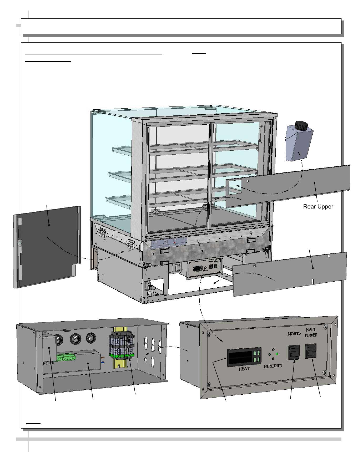
CASE DESIGN, CONT’D: REAR VIEW OF FREE STANDING, SERVICE MERCHANDISERS
2. Rear View Of Free-Standing, Service Merchandisers
• Random free-standing unit is illustrated below.
• Rear panels, side cladding & shipping brace are removed
for illustrative purposes only.
Shelving
(Typ.)
UV-Bonded Glass
Enclosure (Typ.)
Handles
(Typ.)
Thermostat,
Lights And
and Main
Power Switch
Locking Caster
(Typ.)
Magnets For Rear
Upper Panel (Typ.)
Model Shown May Not Exactly
Reflect Every Feature or Option of
Your Particular Case.
Rear Sliding
Doors
Magnet For Rear
Lower Panel
Latch To Secure
Side Panel
Latch To
Secure Side
Panel
Locking Caster
(Typ.)
Magnet For
Rear Lower
Panel
Side Panel
(Typ.)
Rear Lower Panel
Water Fill Funnel
(Optional)
Rear Upper
Panel
Funnel Bracket
Overflow For Humidification System (Optional).
Note: If Unit Was Ordered With Optional Humidification
System, and This Component Is Not Present, Contact
Structural Concepts Corporation.
14
CASE DESIGN, CONT’D: CONTROLLER / LED DRIVER / LIGHTS SWITCH / MAIN POWER SWITCH
3. Thermostat / LED Driver / Lights / Main
Power Switch
• Remove rear lower panel by lifting up and off; no
screw removal is required.
• Remove 4 screws from the controller/DC driver
box cover to access electrical components.
LED Driver
Terminal Strip
Electrical Box
(With Faceplate Removed)
Electrical Box
(With Faceplate Attached)
Main Power
Thermostat
Lights
• Note: Only certified electricians are to access
electrical components in case.
• After accessing controller, return components to
case in reverse order they were removed.
Water Fill Funnel
(Optional)
Rear Upper
Panel
Rear Lower Panel
Side Panel
(Typ.)
Relay
*
*Note: If “HUMIDITY” etching is on faceplate, simply ignore; such markings are not applicable to cases in this manual.
15
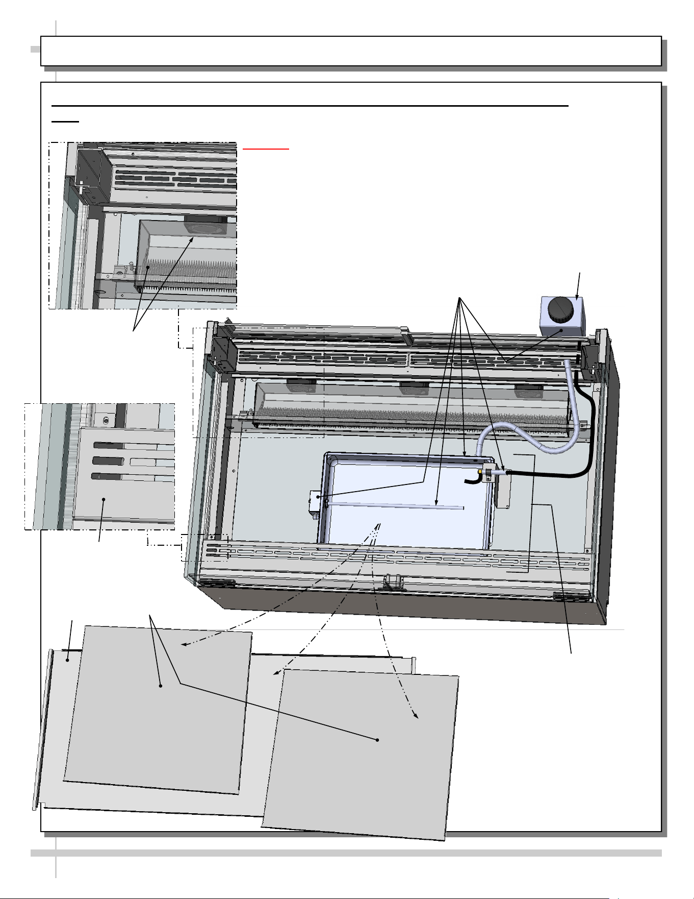
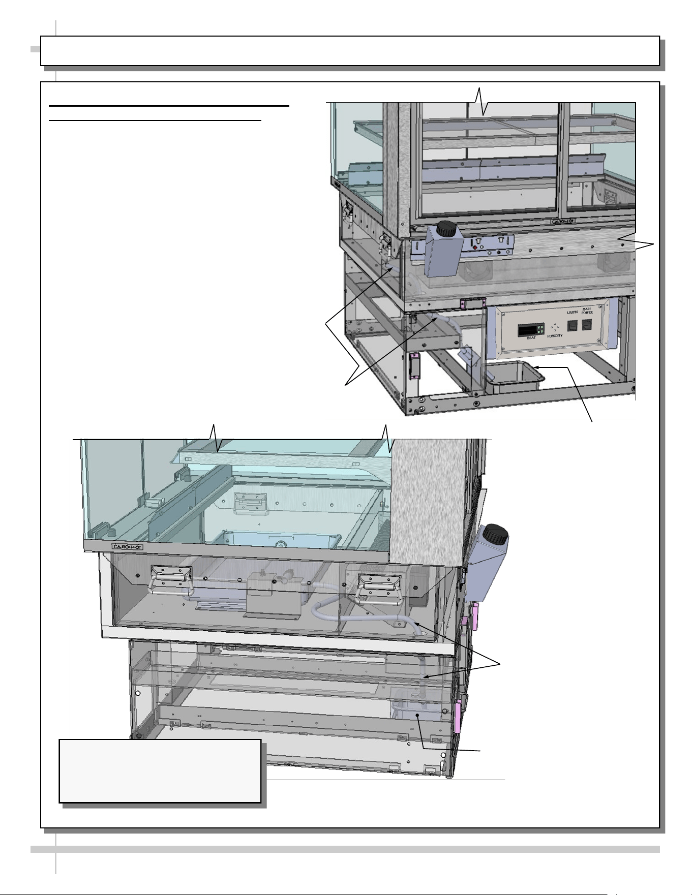
CASE DESIGN, CONT’D: TUB ACCESS / HEATER / POWERED HUMIDIFICATION SYSTEM (OPTIONAL)
4. Tub Area Access / Heater / Powered Humidification System (Optional) Access
Note: Powered humidification system assembly service is to be performed by refrigeration/electrical
contractors only.
Caution! Turn main power off before accessing tub area.
• To access powered humidification system assembly, remove sub-deck
and deck pans. No screw removal is required.
• After cleaning or servicing powered humidification system assembly,
return sub-deck & deck pans to case.
• Restore power to case.
Airflow Baffle
Sub-Deck
Deck Pans
Heater/Fan
Assembly
--- Case Rear ---
Powered Humidification
System Assembly
(Optional)
CAUTION! Powered
Humidification System
Poses An Electric Shock
Hazard! See Next Page
For Specifics.
Water Fill Funnel
(Optional)
--- Case Front ---
16
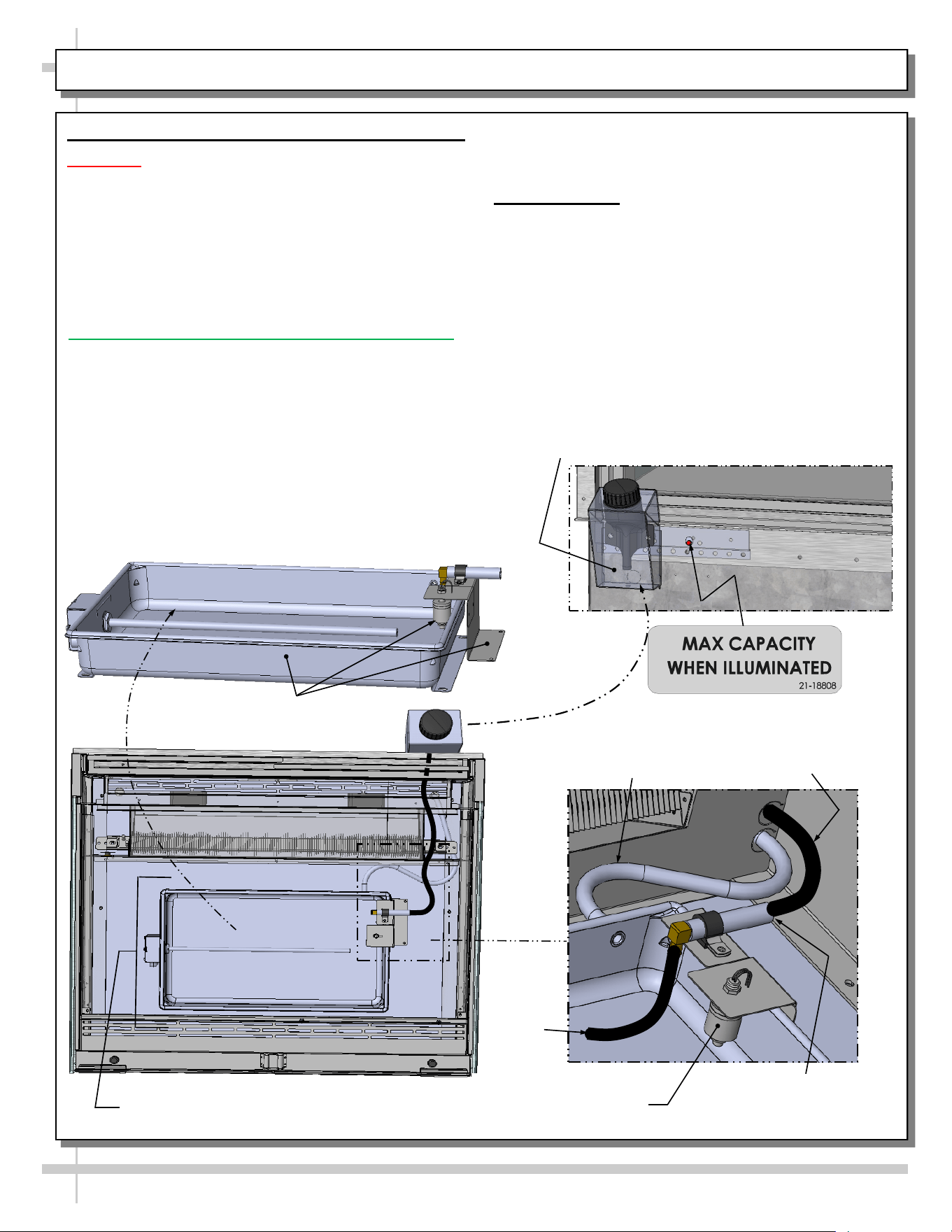
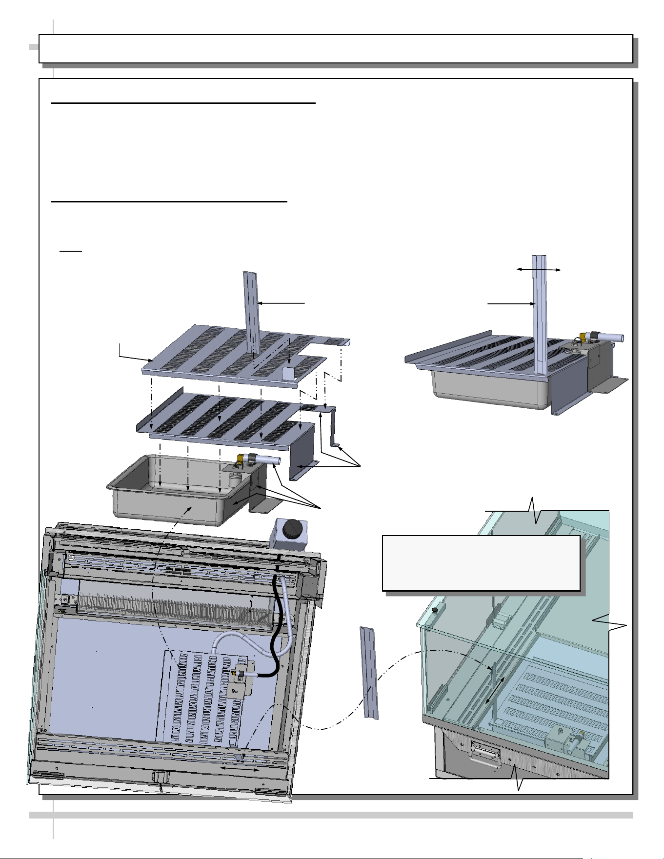
CASE DESIGN, CONT’D: POWERED HUMIDIFICATION SYSTEM (OPTIONAL) / WATER CAPACITY/ TYPE
5. Powered Humidification System (Optional)
CAUTION! ELECTRIC SHOCK HAZARD!
• Overfilling Powered Humidification system can
cause electrical shock.
• LED indicator will alert case operator when MAX
CAPACITY has been reached.
• IMPORTANT! If MAX CAPACITY light
malfunctions, check overflow periodically to
assure that water does not overflow onto floor.
7. Type of Water
• Use ONLY distilled water (to prevent corrosion of
electrical & mechanical components).
• DO NOT use deionized water, as it may damage
heating element.
• Regardless of type of water utilized, regular
cleaning must be performed to prevent residue,
lime and mineral deposits. See PREVENTIVE
MAINTENANCE section in manual for funnel and
cleaning instructions.
• DISCONTINUE filling the funnel (shown at right)
when Powered Humidification system is FULL (and
MAX CAPACITY is reached).
6. Water Capacity - Important! Please Read!
• Capacity of MOST units is 7 quarts.
• Capacity of SMALLER units (NR3633HSV,
NR4833HSV and ALL PASSIVE HUMIDIFICATION
UNITS ) is only 3.5 quarts
• At initial fill, ADDITIONAL water will be required for
the water fill funnel.
• Do NOT overfill (see above for warnings).
• IMPORTANT! If humidification system overfills, you
must check overflow at rear of case. See next page
its location and illustration.
Powered
Humidification System
Connect
Quick-Connect Coupling
Here (For Water Inlet)
Water
Inlet
Hose
Float (Activates
Humidification System
Based On Water Level)
Hose From Water Fill
Funnel (Optional) To
Humidification System
Hose From
Humidification
System To Overflow
Powered Humidification System
(To Be Attached To Tub)
--- Case Front ---
--- Rear View of Case ---
Water Fill Funnel
(Optional) / Shown
Transparent
17
CASE DESIGN, CONT’D: OVERFLOW SYSTEM (FOR POWERED & PASSIVE HUMIDIFICATION SYSTEMS)
8. Overflow Systems (For Powered or
Passive Humidification Systems)
• An easily viewable overflow is located at the
lower-rear of case.
• Important! Overflow MUST BE emptied
regularly to prevent overflowing onto
floor!
• IMPORTANT! If Humidification system
overfills, you must check overflow
(shown).
• IMPORTANT! If MAX CAPACITY light
malfunctions, you must check overflow
periodically to assure that water does not
overflow onto floor.
• Partially transparent and disassembled
illustrations are shown at right and below.
Overflow For
Optional Humidification
System
Overflow For
Optional Humidification
System
Hose From Optional
Humidification System
To Overflow
Hose From Optional Powered
(or Passive) Humidification
System To Overflow
Partially Disassembled And
Transparent Model (Shown) May Not
Exactly Reflect Every Feature Or
Option of Your Particular Case.
18
CASE DESIGN, CONT’D: PASSIVE HUMIDIFICATION SYSTEM (OPTIONAL) / HUMIDITY CONTROL LEVER
9. Passive Humidification System (Optional)
• Passive Humidification Systems are ONLY ON SMALL
UNITS (NE3613HSV & NE4813HSV).
• Cases with these systems DO NOT have humidity
controlled by thermostat (at case rear).
• Instead, humidity is controlled by sliding the outer
cover’s control lever either left or right (as shown below).
10. Humidity Control Via Lever and Key
> Access the humidity control lever by inserting the control
lever key THROUGH front grille slot and attaching it to outer
cover’s lever.
> Note: Access to humidification cover/lever may ALSO be
gained by opening doors and removing decking (see page
15 for specifics on deck removal).
Passive
Humidification
System
Control Lever
Key
Passive Humidification System
(To Be Attached To Tub)
Passive Humidification System Cover -
Inner (To Be Attached To Tub)
A. If product seems to be drying out, simply slide the lever
to the left (OPEN POSITION); more humidity will fill case,
making product more moist.
B. If product seems to be overly moist, simply slide
lever to the right (CLOSED POSITION); less humidity will
permeate case, making product less moist.
C. Passive Humidification System lever can be
PARTIALLY OPENED (by sliding lever midway along slot) to
incrementally control humidification (and product
moistness) in case.
> Caution! The humidification control lever key has
magnet to allow it to be stored/attached at case rear
so it is not lost! See next page for illustration
showing key storage/placement.
Passive Humidification System
Cover - Outer (Controls
Humidity Depending
Upon Its Position)
Humidification Control Lever Key To
Be Attached to Lever (Controls Humidity
Depending Upon Its Position )
Left Right
--- Passive Humidification System Assembly ---
Partially Disassembled And
Transparent Model (Shown) May Not
Exactly Reflect Every Feature Or
Option of Your Particular Case.
19
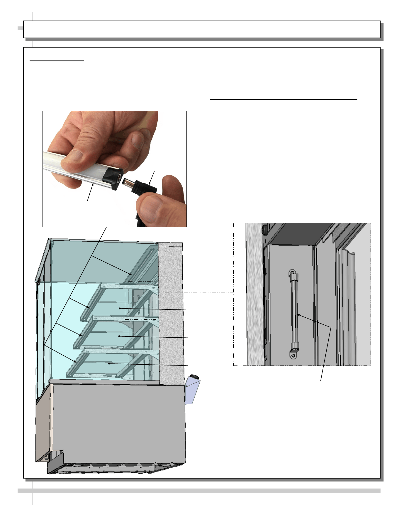
CASE DESIGN, CONT’D: LED LIGHT CONNECTION / THERMOMETER FUNCTION & PLACEMENT
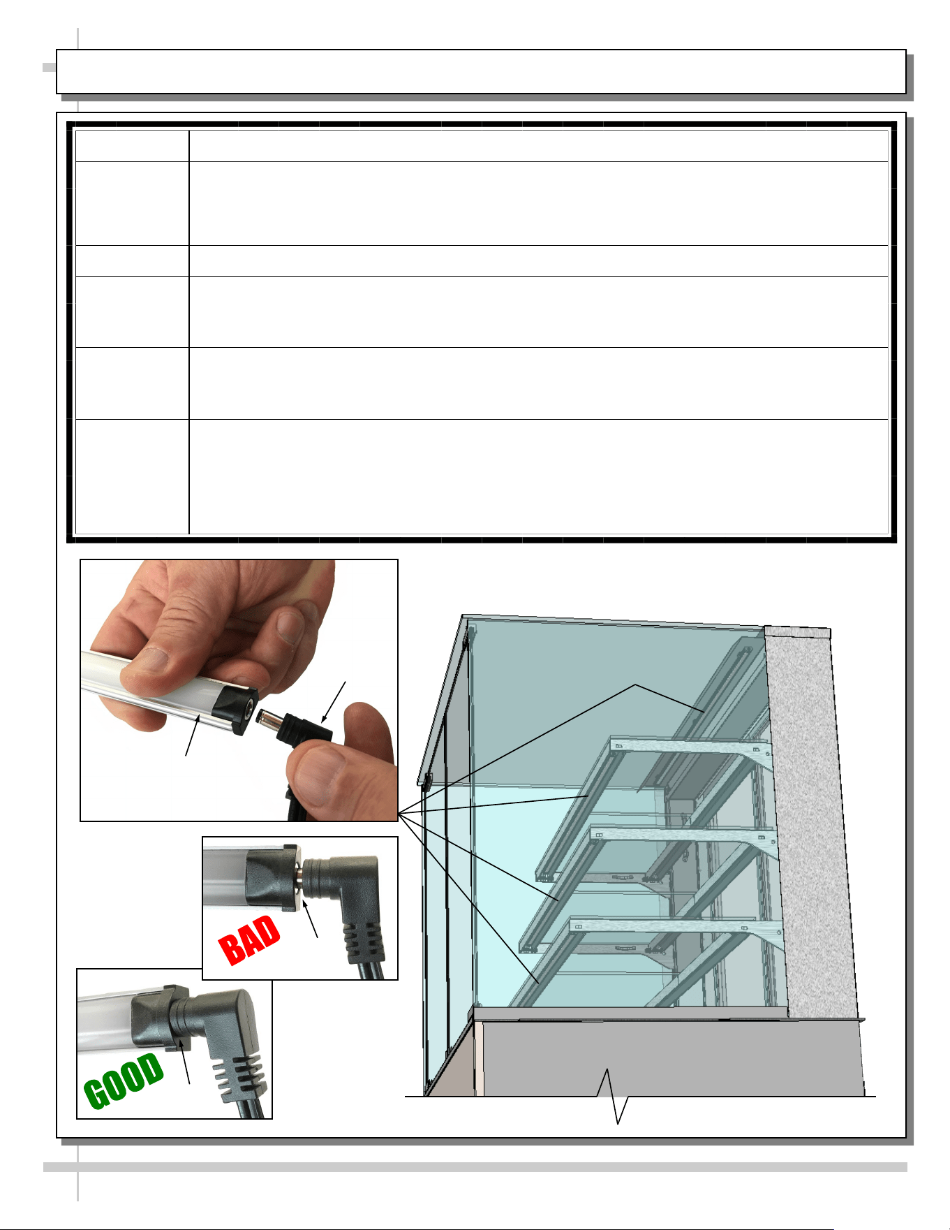
11. LED Lights
• LED lights are located at both header and
shelving of case (as shown below).
• Check that ALL of the light plugs are properly
connected to the LED light.
Middle Shelf
Lower Shelf
• Plug must be inserted ALL THE WAY into the
LED light orifice (with no gap) to work properly.
• See TROUBLESHOOTING section in manual
if LED lights malfunction.
12. Thermometer Function & Placement
• Thermometer provides air temperature of
heated section of case.
• Thermometers DOES NOT provide actual food
temperature.
• Use probe thermometer to determine actual
product temperatures.
Top Shelf
LED Light
Plug
Thermometer Shown
(Shelving Removed For
Illustrative Purposes Only)
20
CASE DESIGN, CONT’D: REAR SLIDING DOOR REMOVAL / REPLACEMENT
13. Rear Sliding Door Removal / Replacement
• To remove rear sliding doors, move rear doors toward center
of the case.
• Individually lift each door up toward the top of the case; pivot
the bottom of the door out.
• Return doors to case in reverse order they were removed.
Free-Standing Unit (Shown) May Not
Exactly Reflect Every Feature or
Option of Your Particular Case.
21
CASE STARTUP: HEATER SETTINGS / LIGHTS SWITCH / SHUTTING DOWN CASE / KEY STORAGE
3. Light Switch
• Turn lights switch “ON” to turn on lights.
• All LED lights will come on at the same time.
4. Shutting Down Case
• Remove all product from case.
• Turn main power switch to “OFF” position.
• Caution! Deck and shelving is hot. Allow case
to cool for 45 minutes before cleaning.
• Note: When main power is turned back on, you do
NOT need to re-enter settings. Temperatures will
revert back to LATEST SETTINGS before
shutdown.
5. Control Lever Key Storage Location
• For units with passive humidification systems, a
control lever key is provided. It is designed with a
magnet to hold it securely.
• Control lever key may be stored at case rear
(as shown in illustration).
1. Main Power Switch
• Control panel (at case rear) is accessible by
removing lower-rear panel.
• Turn main power switch “ON” to energize case.
2. Heating Up Case / Adjusting Settings
• Note: Case is designed to MAINTAIN product
temperatures – NOT heat up product! Do not place
product that is cold or ambient temperature in case.
• Before placing pre-heated food in case, allow
1 1/2 hours (90-minutes) for case to achieve its
desired temperature.
• If adjusting heater settings, allow 20 minutes at
new settings for temperature to affect product.
Model Shown May Not Exactly
Reflect Every Feature or Option
of Your Particular Case.
Programmable
Controller
Lights
Switch
Main Power
Switch
Lower Rear
Panel
Recommended Storage Location
of Humidity Control Lever Key
(Via Magnet on Key)
*
*Note: If “HUMIDITY” etching is on faceplate, simply ignore; such markings are not applicable to cases in this manual.
22
START-UP AND OPERATION, CONTINUED: LOAD LIMITS
22
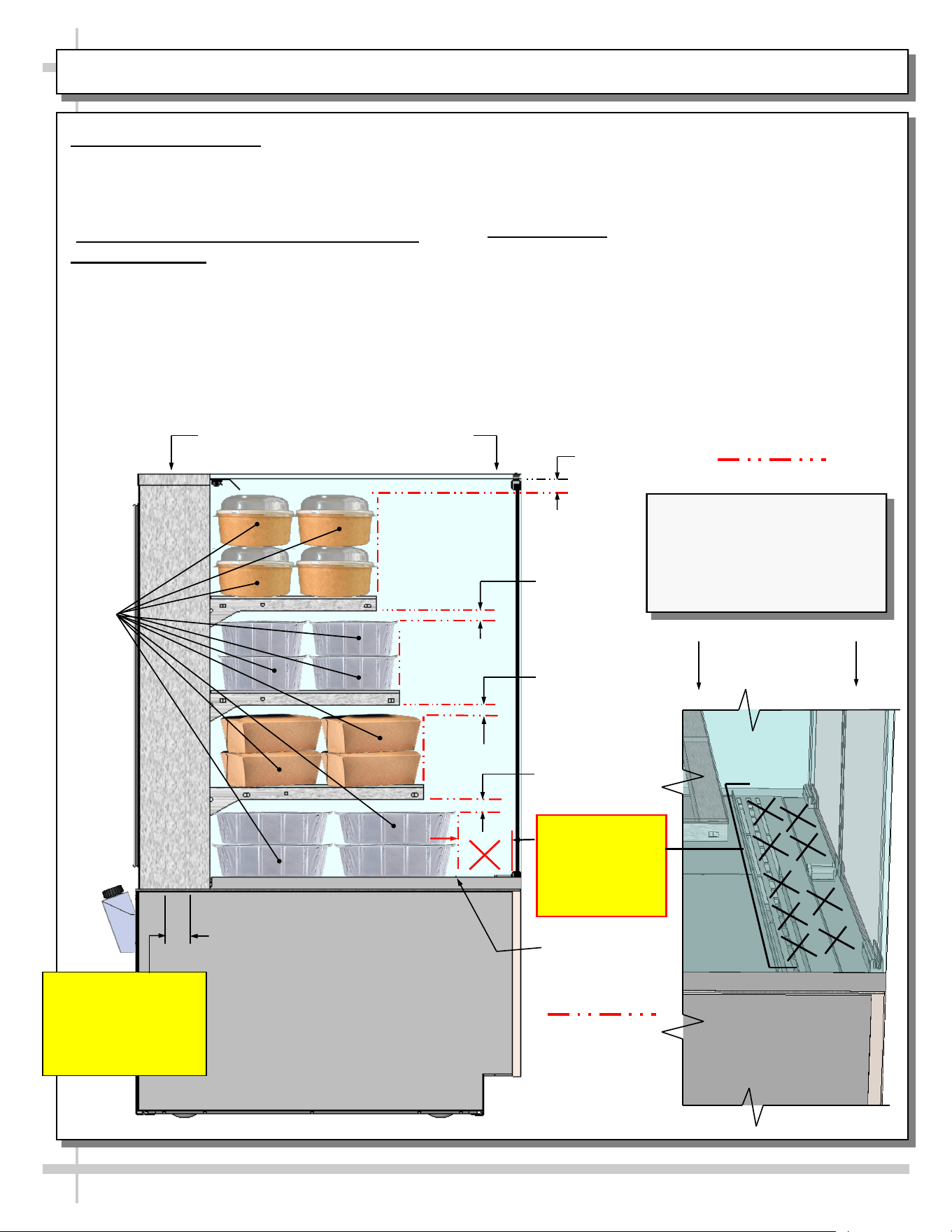
PRODUCT PLACEMENT / AIRFLOW CONSIDERATION / LOAD LINES
• Caution! For discharged air to reach the return air
grille, you must not block front OR rear grilles with
product.
• Do not place product on front ledge of case.
3. Load Lines
• Load lines represent the limit that product can be
place (either horizontally or vertically) and/or
stacked in case.
• Keep product at or under load lines to assure that
heated airflow is properly cycled from air diffuser
through return air grille.
• Proper product placement will maintain
acceptable product temperature.
• See illustration below.
1. Product Placement
• Product can be placed on decking or steps
(risers) within the service display area.
• A wide range of product may be displayed.
2. Air Diffuser Grille & Return Air Grille
Considerations
• Proper airflow is critical to maintain proper
product temperature.
• Proper product placement will allow front air to
flow over (and around) product to return air grille
at case rear. See illustration below for specifics.
Angled View Of
Discharge Air Grille
Load Lines
1” Minimum
Load Line
Sample
Product (Typ.)
1” Minimum
Load Line
1” Minimum
Load Line
1” Minimum
Load Line
Model NR3655HSV (Shown)
May Not Exactly Reflect Every
Feature or Option of Your
Particular Case. However,
General Airflow Consideration
and Load Line Guidelines Apply.
Model NR3655HSV Shown Below
Caution!
Convertible 1.25”
Air Diffuser Grille
At Rear Inner.
Do Not Block!
Load Lines
Caution!
Do Not Place
Product On
Discharge Air
Grille Or Ledge
Product Stop
23
CLEANING SCHEDULE (TO BE PERFORMED BY STORE PERSONNEL)
FREQ. INSTRUCTIONS
Daily Glass Surfaces (Including Shelves): Clean glass surfaces and shelves with household or
commercial glass cleaner.
Daily Water Inlet Funnel (Optional) At Rear of Case:
> Raise lid. Remove/drain water. Spray with disinfectant. Wipe out/remove residue. Refill with
distilled water.
Daily Rear Sliding Door Exterior Glass: Clean with household or commercial glass cleaner. Clean out
rear door track with moist cloth.
Daily End Panels, Front Panel, Toe-Kick, etc.: Wipe off all surfaces with warm water and mild soap
solution and non-abrasive cloth.
Daily Decks: Wipe off decks with moist cloth dipped in mild soap and water solution.
Daily Stainless Steel Surfaces:
• Wash with a solution of hand dishwashing liquid detergent and water or a solution of baking
soda and water. Rinse and polish dry with paper towel or soft cloth.
• Never use scouring powders or steel wool as they will scratch stainless steel.
• Brighten by polishing with a cloth dipped in vinegar or in ammonia; sprinkle baking soda on
sponge and rub gently; rinse. Polish dry with paper towel.
• Remove streaks or heat stains from stainless steel by rubbing with club soda.
Quarterly Under Case Cleaning:
• Remove front and/or lower rear panel.
• Use broom or vacuum to remove all dust, dirt, food particles or residue from underside of case.
• For units with optional humidification system, check overflow; if it needs to be emptied or
cleaned, do so.
• Replace front and/or lower rear panel after cleaning.
24
FREQ. INSTRUCTIONS
Quarterly
Tub Area:
• Caution! Turn off power to case. Allow case to cool for 45 minutes before proceeding.
• Open front doors to access decking.
• Remove sub-deck and deck pans. See CASE DESIGN, CONT’D: TUB AREA / HEATER /
OPTIONAL POWERED HUMIDIFICATION SYSTEM ACCESS section in manual for
instructions and illustrations.
• Wipe down tub, axial fans and deck pan.
• Thoroughly clean humidification system to remove residue and grime. Use disinfectant/germicide
in spray bottle to kill bacteria. Rinse with clean water in spray bottle.
• Return subdeck and deck pans to case.
• Restore power to case.
Quarterly Cleaning Optional Powered & Passive Humidification Systems
Preparation:
• Caution! Turn off power to case. Allow case to cool for 45 minutes before proceeding.
• Open front doors to access decking.
• Remove sub-deck and deck pans. See See CASE DESIGN, CONT’D: TUB AREA / HEATER /
OPTIONAL POWERED HUMIDIFICATION SYSTEM ACCESS section in manual for
instructions and illustrations.
• Use wet/dry vacuum to empty the humidification system of water.
Humidification System:
• For Passive Humidification Systems only, remove stainless steel cover (two pieces) from case.
Submerse in warm, soapy water and clean thoroughly with soft-bristled brush. Rinse. Dry. Return
to case AFTER the humidification system cleaning process has been completed.
• For cleaning humidification system, use a mixture of 75% water / 25% unflavored white vinegar to
fill the rear water inlet funnel.
• Set control panel’s HUMIDITY setting at its highest (9) and allow unit to run for 30 minutes.
• Use a soft-bristled brush to dislodge the lime/calcium accumulation from the humidification system.
• Turn off main power switch and allow the unit to cool.
• Use wet/dry vacuum to remove the de-liming solution from the humidification system.
• Use a clean sponge and/or clean rags to sop up any remaining de-liming solution.
• Then, using clean, pure water, fill and drain the humidification system until any remaining water
and/or white vinegar solution is rinsed through and the water discharge is clean.
Water Inlet Funnel Hose and Hose From Humidification System Pan To Overflow:
• Remove the water inlet funnel (from case rear); disconnect from hose. Submerse in warm, soapy
water. Clean with soft-bristled brush. Rinse. Dry. Return it to case rear. Securely reconnect hose
to water inlet funnel.
• Check that hose to BOTH water inlet funnel and humidification system is supple and in good
condition; If cracking or showing signs of fatigue, contact Structural Concepts for
replacement.
• Turn power back on and fill the water inlet funnel back up (as described in the CASE DESIGN,
CONT’D: POWERED HUMIDIFICATION SYSTEM / WATER CAPACITY/TYPE section of this
manual).
WARNING! TURN OFF CASE BEFORE PERFORMING PREVENTIVE MAINTENANCE!
PREVENTIVE MAINTENANCE (TO BE PERFORMED BY TRAINED SERVICE PROVIDER)

25
TROUBLESHOOTING (TO BE PERFORMED BY STORE PERSONNEL) - PAGE 1 OF 2
CONDITION TROUBLESHOOTING
Water Is On
The Floor
Water on floor can cause extensive damage to flooring! Resolve immediately.
> For units with optional heated humidification system, check overflow (at rear of case).
See CASE DESIGN, CONT’D: POWERED HUMIDIFICATION SYSTEM / WATER
CAPACITY/TYPE section in manual for water capacity specifics. Important! You must
check overflow periodically (at least weekly) to make sure it is not going to overflow.
Also, to be able to always SEE overflow state, it may be a good practice to REMOVE
lower end panel!
> Check condition of BOTH the humidification system fill funnel hose and overflow
hose. If they are cracking or show fatigue, they must be replaced. Contact Structural
Concepts Corp. for replacement hose(s).
> Check connections (including quick-connects) and/or clamps on all hoses. If loose
or poorly connected, tighten securely.
• Access to water fill funnel connector is gained by lifting it up and off rear of case.
• Access to humidification system is gained by removing decking. Caution! You
must turn off power to case and allow to cool for 30 minutes before accessing
components under decking!
• See CASE DESIGN, CONT’D: POWERED HUMIDIFICATION SYSTEM / WATER
CAPACITY/TYPE After checking all the above, if water is still dripping onto floor,
call service provider.
Poor or No
Humidification
> Check that heating element works (on water inlet side).
> Check that float is functional. See CASE DESIGN, CONT’D: POWERED
HUMIDIFICATION SYSTEM / WATER CAPACITY/TYPE section in manual for location/
illustration. If it is malfunctioning call service provider.
> Humidity is to be adjusted based on product.
• Adjust humidity control by adjusting controller (at case rear).
• Raise humidity level one point at a time (e.g., if humidity level is at “5”, press the “up”
key to change it to “6”).
• See CASE DESIGN, CONT’D: MAIN POWER / LIGHTS / PRE-HEAT /
OPERATION / SHUTTING DOWN section specifics on adjusting humidity.
Fan Noise Is
Excessive
Call service provider.
Case is Not
Holding Proper
Temperature
If a large amount of cool (or ambient) product was added to the case, it will take time
for the temperature to adjust. Product must be pre-heated before placing in case.
See PROGRAMMABLE CONTROLLER INFORMATION section in this User Manual for
thermostat specifics.
• Check air return grilles (area at front of decking) for obstructions.
• DO NOT set product on air grilles as this will prevent proper airflow!
• See PRODUCT PLACEMENT / AIRFLOW CONSIDERATION / LOAD LINES
section in manual for product placement guidelines.
Check that the case is not in the sun. See OVERVIEW / THERMOMETER /
COMPLIANCE / WARNINGS / PRECAUTIONS section in this manual for specifics.
If case still is not holding proper temperature, call service provider.
26
TROUBLESHOOTING (TO BE PERFORMED BY STORE PERSONNEL) - PAGE 2 OF 2
CONDITION TROUBLESHOOTING
Case Lights
Not Working
Check that light switch is in the ON position.
• See INSTALLATION, CONT’D: PLUG IN UNIT / TURN ON MAIN POWER SWITCH
AND LED LIGHT SWITCH section in manual for switch location (regardless of case
design).
If case is not hard-wired, check that power cord is properly connected to wall outlet.
Check that ALL of the light plugs are properly connected to the LED light.
• Plug must be inserted ALL THE WAY into the LED light orifice (with no gap).
• See illustrations below-left.
Power may not be reaching the case.
• Contact store management to have trained service provider perform troubleshooting.
• Troubleshooting to be performed by trained service providers only is on next page.
If case light still do not come on, it may need to be replaced.
• Contact Structural Concepts’ Technical Service Department for replacement light
(see TECHNICAL SERVICE section of this manual for contact information).
• To replace, disconnect plug from existing LED light. Disconnect LED light from its
brackets. Replace with new LED light. Insert plug ALL THE WAY into LED light orifice.
No Gap
Gap
LED Light
Plug
27
TROUBLESHOOTING (TO BE PERFORMED BY TRAINED SERVICE PROVIDERS ONLY), PAGE 1 OF 2
CONDITION TROUBLESHOOTING
Water Is On The
Floor
Caution! If too much water fills humidification system, case is designed for water to
overflow at rear of case.
• IMPORTANT! If humidification system overfills, you must check overflow at
rear of case.
• IMPORTANT! If MAX CAPACITY light malfunctions, you must check overflow
periodically to assure that water does not overflow onto floor.
• IMPORTANT! If humidification system overfills, you must soak up excess
water from floor with sponge. Otherwise, water on floor can cause damage.
Fans Emit
Excessive Noise
Check that the case is aligned, level and plumb.
Check axial fans for cleanliness.
Check that fan motors are securely mounted in brackets.
Check that nothing is preventing blade rotation.
Check that the fan shroud is properly secured.
Fans Are Not
Working
Check that the MAIN power switch is on.
Check that fans are plugged.
Check for foreign material obstructing fan performance.
Check that fan blades freely rotate within fan shrouds
Check that power is going to fans
Check that fan wiring is connected on terminal blocks.
28
CONDITION TROUBLESHOOTING
Case Lights Are
Not Working
See TROUBLESHOOTING (TO BE PERFORMED BY STORE PERSONNEL)
section in manual for most common troubleshooting solutions.
Check power.
• If power is not supplied to the case, facility may have faulty power distribution.
• If power is supplied to the case but lights are not energized, case’s power supply
may be faulty.
Case Is Not
Holding
Temperature
If a large amount of product was added to the case, it will take time for the
temperature to adjust.
Check that case is not in sun or near a heat or air-conditioning vent.
Digital Control
Display Is Blank
Check that the MAIN power switch is on.
Check the circuit breaker box for tripped circuits.
System Is Not
Operating
Check that the utility power is on.
Check that the MAIN power switch is on.
Check the circuit breaker box for tripped circuits.
TROUBLESHOOTING (TO BE PERFORMED BY TRAINED SERVICE PROVIDERS ONLY), PAGE 2 OF 2
29
SERIAL LABEL LOCATION & INFO LISTED / TECH INFO & SERVICE - AMBIENT/HEATED CASES ONLY
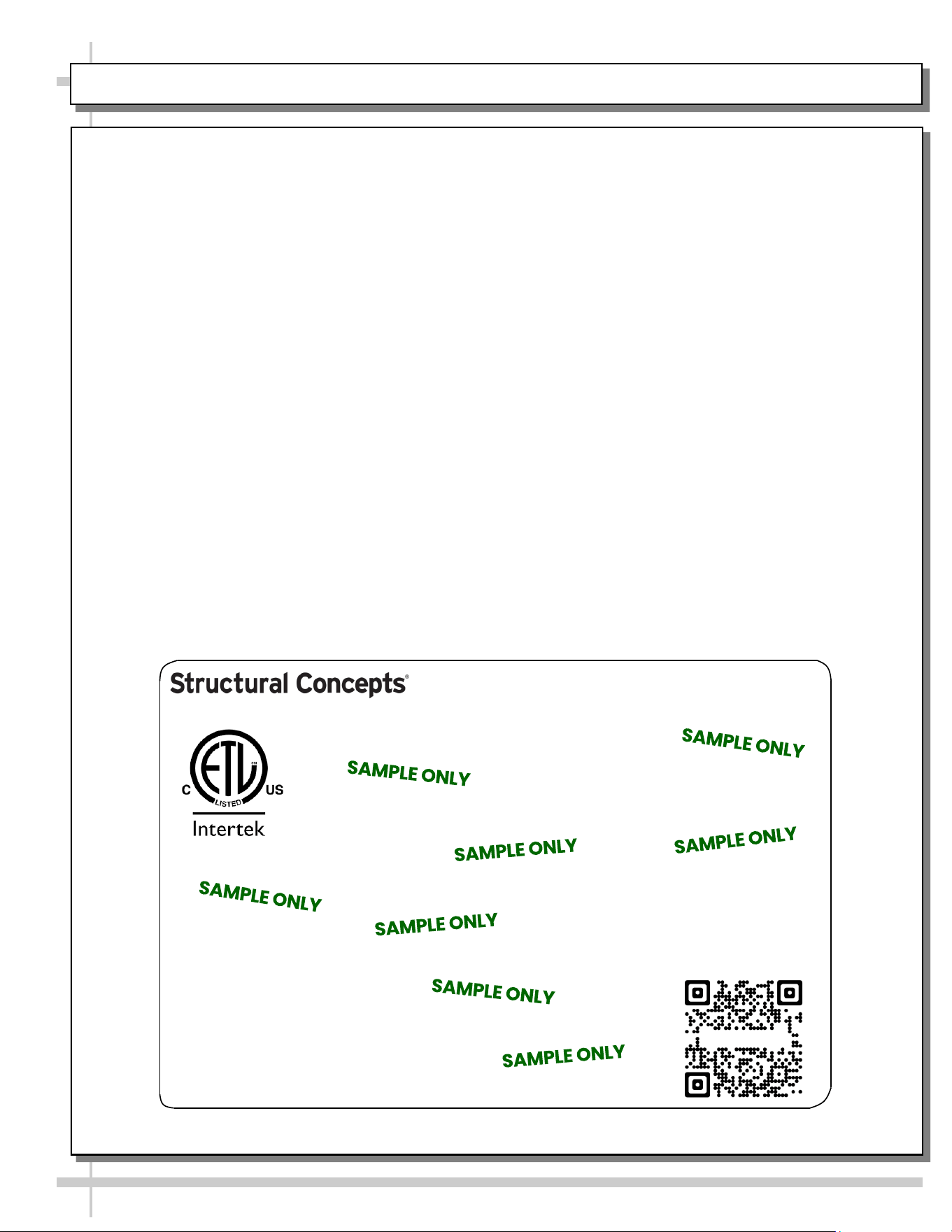
--- Sample Serial Label For Ambient/Heated Cases ---
MODEL NRS3648RXV-SAMPLE
SERIAL NO. 12345X30DZ098765
888 E. Porter Rd - Muskegon, MI 49441
3048256
Conforms to UL Std. 65
CERTIFIED TO CAN/CSA
STD C22.2 NO 120
120 VOLTS 60HZ
FOR PARTS OR SERVICE CALL
STRUCTURAL CONCEPTS
AT 1-800-433-9489
SINGLE PHASE 1.84 AMPS
Serial Label Location & Information Listed /
Technical Information & Service
• Serial labels are affixed at a wide range of places
(on the header, at case rear, behind panels or
toe-kicks, on electrical boxes, etc.).
• Serial labels contain electrical information as well
as regulatory standards to which the case
conforms.
• Sample serial label shown below.
• For additional technical information and service, see
the TECHNICAL SERVICE page in this manual for
instructions on contacting Structural Concepts’
Technical Service Department.
Sample QR Code
SCAN FOR PRODUCT LITERATURE
Reveal
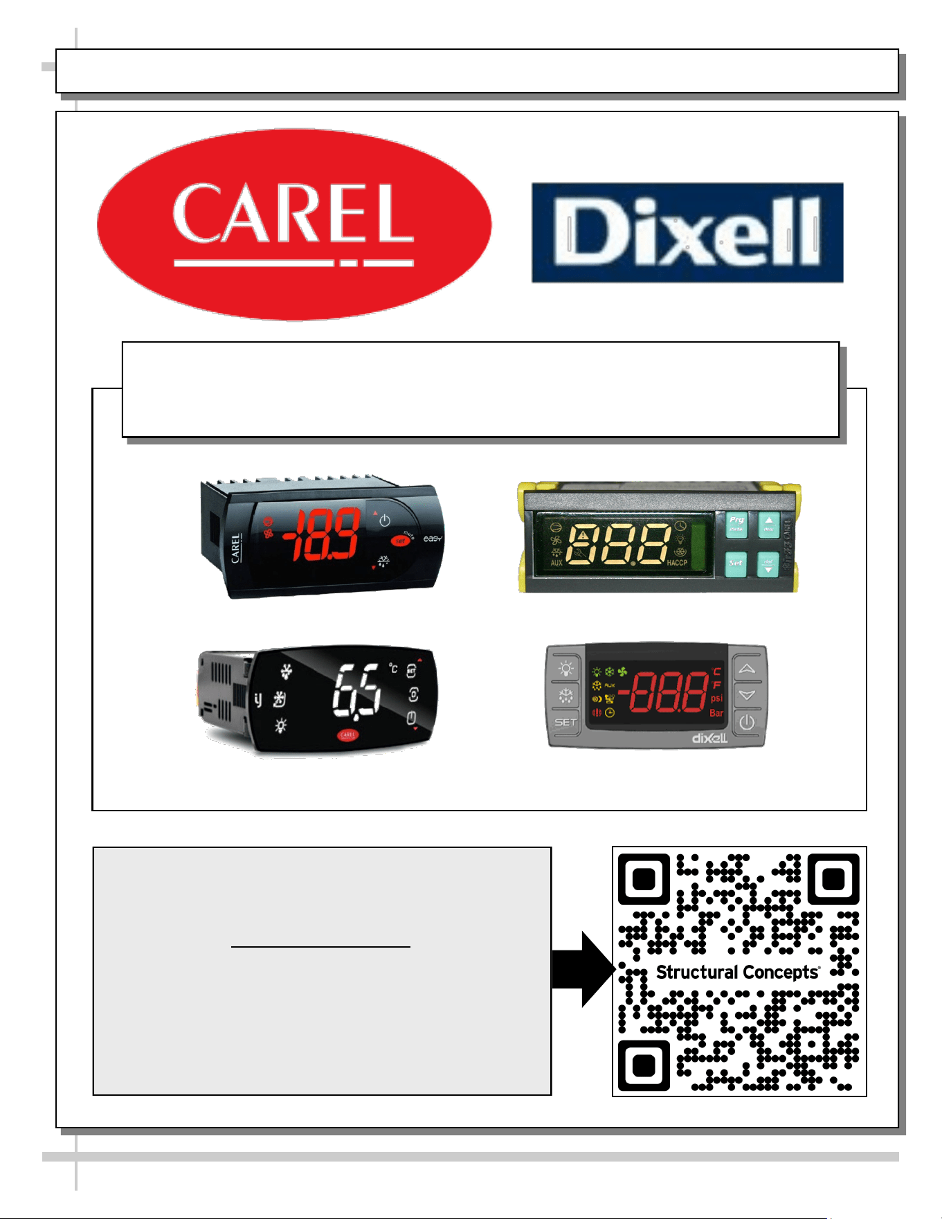
PROGRAMMABLE CONTROLLER (SELECT, CLICK ON OR SCAN QR CODE FOR INFORMATION)
30
Carel® iJF Platform
Carel® PJEZ Platform
Carel® ir33 Platform
Dixell® XM670K-XM679K Platform
To Access Information About The Programmable
Controller That Is Used On Your Case,
Follow These Instructions:
> If Viewing This Document on Smart Phone, Tablet
or Computer, Select/Click On The QR Code at Right.
> If Viewing This Document In Print (Hard Copy),
Scan The QR Code at Right With Your Smart Phone
or Tablet.
Determine Which Programmable Controller Is On Your Case (Controllers
That Are Commonly Used By Structural Concepts Are Shown Below).
Your Particular Programmable Controller May Differ.
STRUCTURAL CONCEPTS TECHNICAL SERVICE CONTACT INFORMATION & LIMITED WARRANTY
31
TECH SERVICE/WARRANTY CONTACT INFO:
1 (800) 433-9490 / EXTENSION 1
DAYS/HOURS AVAILABLE:
MONDAY - FRIDAY (CLOSED HOLIDAYS)
8:00 a.m. TO 5:00 p.m. EST
YOU MUST HAVE THE FOLLOWING INFO AVAILABLE
BEFORE CONTACTING STRUCTURAL CONCEPTS:
SERIAL NO. / MODEL NO. / STORE NO. / STORE
ADDRESS / DETAILS (PHOTOS, LEAK LOCATIONS,
DAMAGE, STORE’S AMBIENT CONDITIONS, ETC.)
To Access The Limited Warranty To Your
Case, Follow These Instructions:
> If Viewing This Document on Smart Phone,
Tablet or Computer, Select/Click On The QR
Code at Right.
> If Viewing This Document In Print (Hard
Copy), Scan The QR Code at Right With Your
Smart Phone or Tablet.