1
Owner’s Manual
Manual del Usuario
Westinghouse Lighting, Philadelphia, PA 19154-1029, U.S.A. www.westinghouselighting.com and Westinghouse are trademarks of Westinghouse Electric Corporation.
Used under license by Westinghouse Lighting. All Rights Reserved. Made in China
W-811
083024

2
3
INSTALLATION GUIDE
T8 TYPE A+B LED Tube
CCT Selectable
Direct installation
PARTS/COMPONENTS INCLUDED IN KIT
- Installation Instructions
- LED Tube Lamp
- Luminaire Marking Labels. Only for Type B installation please apply the following lamp replacement label on the retrofit
luminaire after the retrofit kit has been installed, where readily visible by the user during retrofit, and after installation.
Note: This product complies with Part 18 of the FCC rules but may cause interference to radios, televisions, wireless
telephones and remote controls. If interference occurs, move the product away from these devices or plug it into a dierent
outlet. Do not install this product near maritime safety communications equipment or other critical navigation or communi-
cation equipment operating between 0.45-30MHz.
TYPE A Application (PLUG & PLAY, Ballast compatible)
To avoid personal injury and/or possible product damage, the following cautions must be followed:
• Read all safety information and instructions before installation.
• RISK OF ELECTRIC SHOCK. Disconnect power at fuse or circuit breaker before installing or servicing
• Suitable for damp locations - Not for use where directly exposed to water.
• Caution: Only use the control provided with or specified by these instructions to control this lamp. This lamp will not
operate properly when connected to a standard (incandescent) dimmer or dimming control.
• This device is not intended for use with emergency exits.
• CAUTION - RISK OF FIRE. USE ONLY IN PLACE OF FLUORESCENT LAMPS SPECIFIED ON PRODUCT LABEL.
• CAUTION RISK OF FIRE - IF THE LAMP OR LUMINAIRE EXHIBITS UNDESIRABLE OPERATION (BUZZING,
FLICKERING, ETC), IMMEDIATELY TURN OFF POWER, REMOVE LAMP FROM LUMINAIRE AND CONTACT MANUFACTURER.
• CAUTION - RISK OF FIRE. IF LAMP DOES NOT LIGHT WHEN THE LUMINIARE IS ENERGIZED, REMOVE LAMP FROM LUMINAIRE
AND CONTACT LAMP MANUFACTURER OR QUALIFIED ELECTRICIAN.
•
CAUTION - RISK OF FIRE OR ELECTRIC SHOCK. When working with electronics ballast, please check the compatibility list first.
If you do not find your ballast on the list, then please bypass the fixture as a Type B installation or contact us for support.
Do not install the LED tube with the ballast which is not on the ballast compatibility list.
• To prevent damage to lamp, lamp must not be energized when color (CCT) selector switch is changed.
Ballast Compatibility List must be checked prior to installation.
WARNINGS
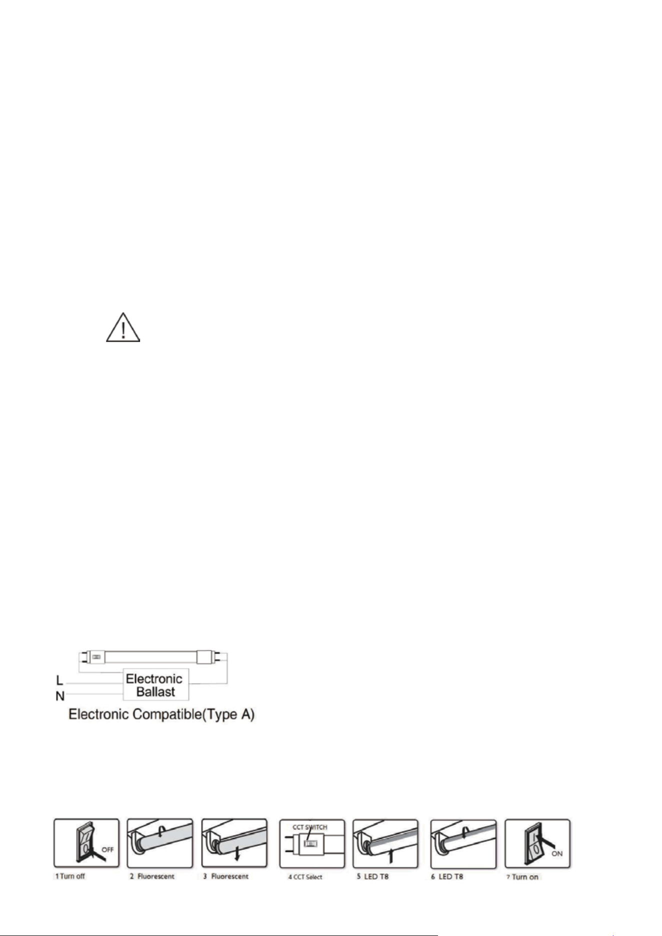
TYPE A - Wring diagram
Type A-Installation Guide
Note: The wiring diagram should be the same with the ballast wiring diagram.
When installing in a ballast, please check the compatibility list first!If you do not find your ballast on the list then please
bypass the fixture, or please contact us! Do not install the LED tube with the ballast which not on the ballast compatibility list.
4
Ballast Bypass installation
NOTE: This equipment has been tested and found to comply with the limits for a Class B digital device, pursuant to Part 15 of
the FCC Rules. These limits are designed to provide reasonable protection against harmful interference in a residential
installation. This equipment generates, uses, and can radiate radio frequency energy and, if not installed and used in
accordance with the instructions, may cause harmful interference to radio communications. However, there is no guaran-
tee that interference will not occur in a particular installation. If this equipment does cause harmful interference to radio or
television reception, which can be determined by turning the equipment o and on, the user is encouraged to try to correct
the interference by one or more of the following measures:
—Reorient or relocate the receiving antenna.
—Increase the separation between the equipment and receiver.
—Connect the equipment into an outlet on a circuit dierent from that to which the receiver is connected.
—Consult the dealer or an experienced radio/TV technician for help.
This Class B digital apparatus complies with Canadian ICES-005.
To avoid personal injury and/or possible product damage, the following cautions must be followed.
• Read all safety information and instructions before installation.
• RISK OF ELECTRIC SHOCK. Disconnect power at fuse or circuit breaker before installing or servicing.
• To prevent damage to lamp, lamp must not be energized when color (CCT) selector switch is changed.
• Suitable for damp locations - Not for use where directly exposed to water.
• Caution: Only use the control provided with or specified by these instructions to control this lamp This lamp will not
operate properly when connected to a standard (incandescent) dimmer or dimming control.
• This device is not intended for use with emergency exits.
• To prevent early lamp failure, lamp should only be installed in operating environments ranging between:
-20°C and +45°C (-4°F and +113°F).
• WARNING - RISK OF FIRE OR ELECTRIC SHOCK. LED Retrofit Kit installation requires knowledge of luminaires electrical
systems. If not qualified, do not attempt installation. Contact a qualified electrician.
• WARNING - RISK OF FIRE OR ELECTRIC SHOCK. Install this kit only in the luminaires that have the construction features and
dimensions shown in the photographs and/or drawings and where the input rating of the retrofit kit does not exceed the
input rating of the luminaire.
• Do not make or alter any open holes in an enclosure of wiring or electrical components during kit installation.
• WARNING - To prevent wiring damage or abrasion, do not expose wiring to edges of sheet metal or other sharp objects.
• Installers should not disconnect existing wires from lamp socket terminals to make new connections at lamp socket
terminals. Instead, installer should cut existing lamp socket leads away from the lamp socket and make new electrical
connections to lamp socket lead wires by employing connectors suitable for the application.
Instructions
1. Switch-o power to the luminaire.
2. Remove diuser (if provided).
3. Remove the existing fluorescent lamps from the luminaire.
4. Select the color temperature through the CCT switch on the LED lamp base.
• Using the color (CCT) selector switch on the base, select the desired color temperature.
• To prevent damage to lamp, lamp must not be energized when color (CCT) selector switch is changed.
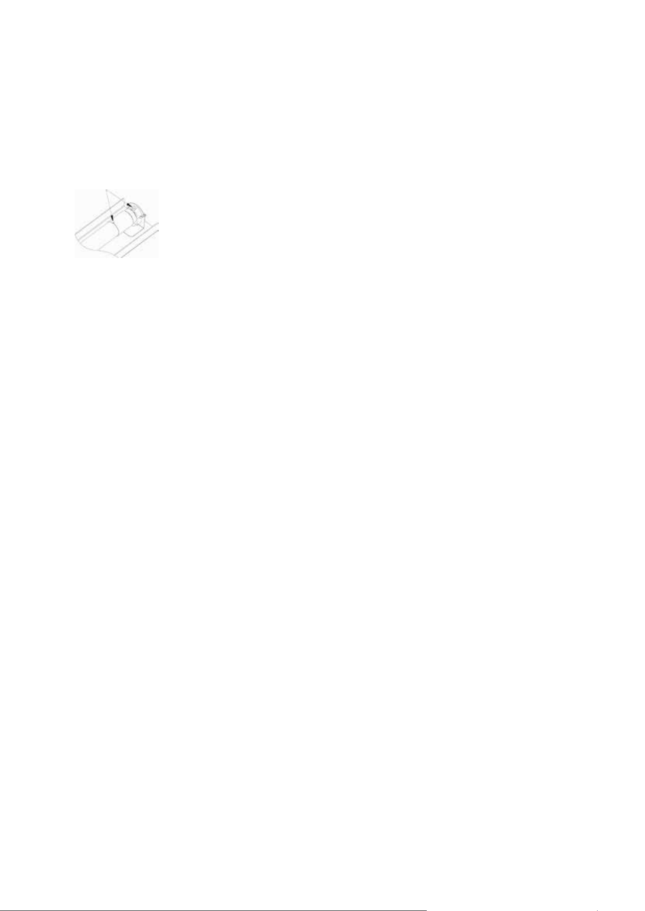
5. Install the LED tube lamp.
Risk of fire, please notice that tube must be well installed. Mark on end caps showing proper alignment with sockets. please
make sure mark is matched with socket as below.
6. Install diuser (if removed in step 2)
7. Switch on power to the luminaire.
8. Before installation, please check specifications for the most current ballast compatibility list, if no match, please insert
led tubes according to below type B installation instructions
WARNINGS
5
Reverse Phase Dimmer Compatibility List
• THIS RETROFIT KIT IS ACCEPTED AS A COMPONENT OF A LUMINAIRE WHERE THE SUITABILITY OF THE COMBINATION SHALL BE
DETERMINED BY AUTHORITIES HAVING JURISDICTION. PRODUCT MUST BE INSTALLED BY A QUALIFIED ELECTRICIAN IN
ACCORDANCE WITH THE APPLICABLE AND APPROPRIATE ELECTRICAL CODES. THE INSTALLATION GUIDE DOES NOT
SUPERSEDE LOCAL OR NATIONAL REGULATIONS FOR ELECTRICAL INSTALLATIONS.
• Examine all parts that are not intended to be replaced by the retrofit kit for damage and replace any damaged parts prior to
installation of the retrofit kit.
• The tube is installed as Type B, the luminaire, once modified as retrofit fixture, will no longer operate fluorescent lamps.
• For a linear tubular LED lamp conversion, there shall be text or a diagram showing how the supply connections were made
to the lamp holders so the correct connections will be made to the lamp when the lamp is installed or replaced.
OR
OR
OR
Important Notes:
• For single-ended wiring installation of tubes, un-shunted lamp holders must be used.
• For double-ended wiring installation, it is not needed to change the sockets/lamp holders (if they are in good condition)
regardless of the type of sockets.
Type B-Installation Guide:
Please completely comply with these instructions and notes to ensure that the product is operated in a safe condition.
Important safety information - read all instructions before installation.
Instructions
1. DISCONNECT POWER OF LUMINAIRE
Disconnect power to luminaire or circuit (if possible). Ensure all power is o by using a voltmeter or other method to confirm.
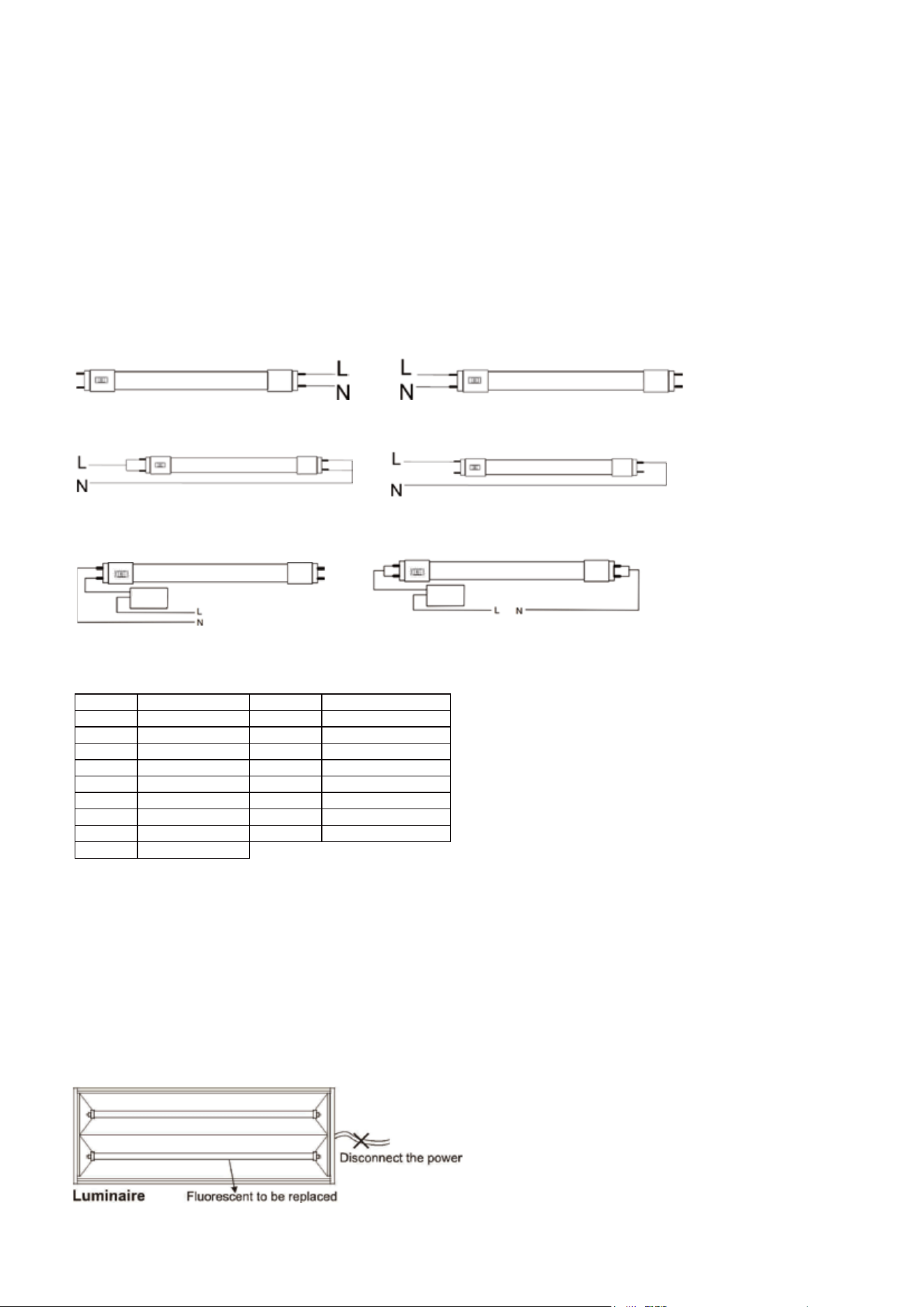
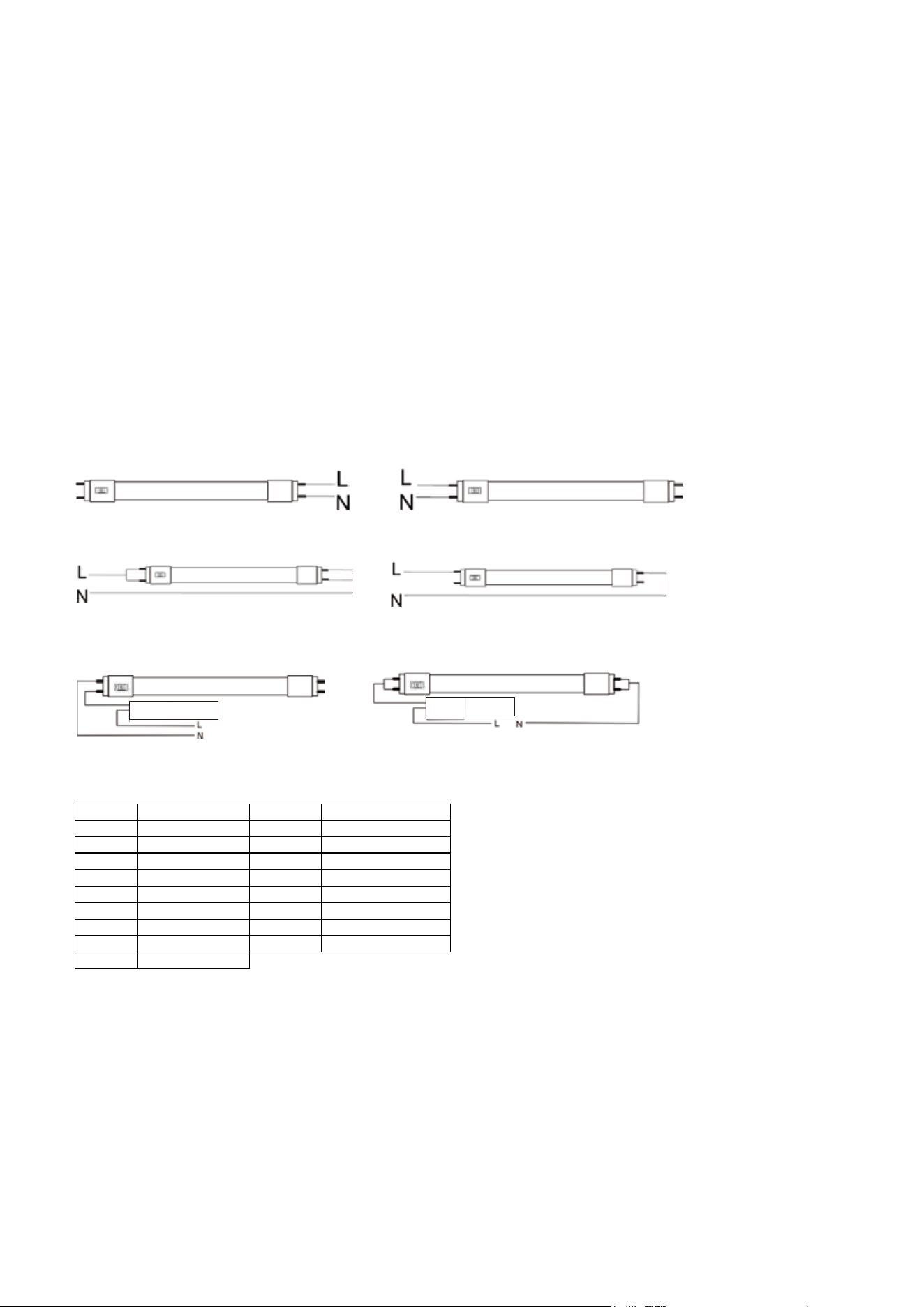
TYPE B - Wring diagram
Connect two wires to branch circuit Land N according to the below figure
Case 1: Direct AC wiring diagram without dimming
1. Single-ended power input
Case 2: Direct AC wiring diagram with reverse phase dimming (Refer to dimmer compatibility list)
Single-ended power input Double-ended power input
2. Double-ended power input
Input Voltage:120-277V 50/60Hz
Input Voltage:120-277V 50/60Hz
Input Voltage: AC120-277V 50/60Hz
BRAND
MODEL NUMBER
BRAND
MODEL NUMBER
LUTRON
DVELV-300P-BR
LUTRON
DVELV-303P-WH
LUTRON
DVELV-300P-GR
LUTRON
MAELV-600-AL
LUTRON
DVELV-300P-IV
LUTRON
MAELV-600-BL
LUTRON
DVELV-300P-LA
LUTRON
MAELV-600-BR
LUTRON
DVELV-300P-WH
LUTRON
MAELV-600-GR
LUTRON
DVELV-303P-BR
LUTRON
MAELV-600-IV
LUTRON
DVELV-303P-GR
LUTRON
MAELV-600-LA
LUTRON
DVELV-303P-IV
LUTRON
MAELV-600-WH
LUTRON
DVELV-303P-LA
Phase cut
dimmer
Phase cut
dimmer
6
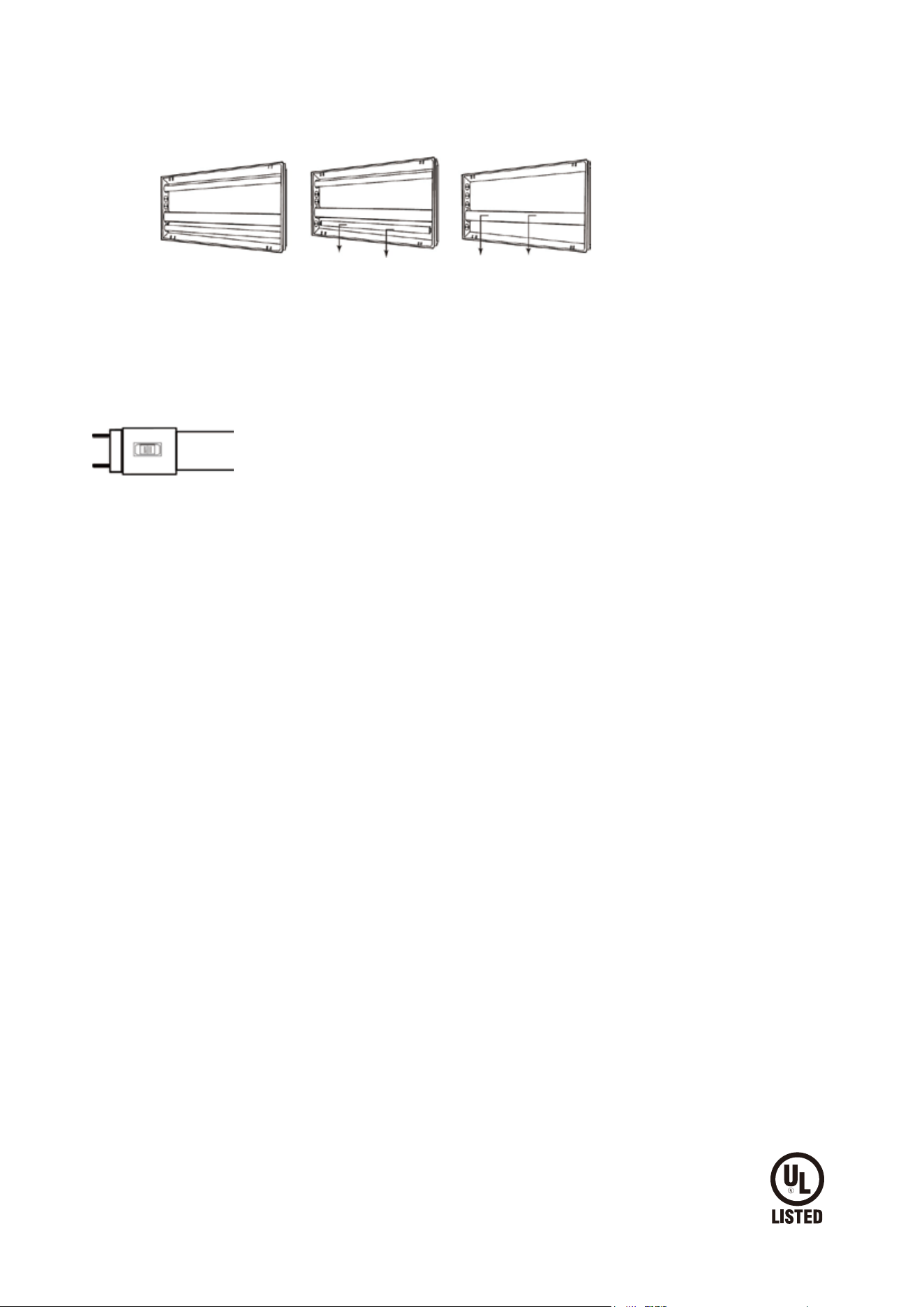
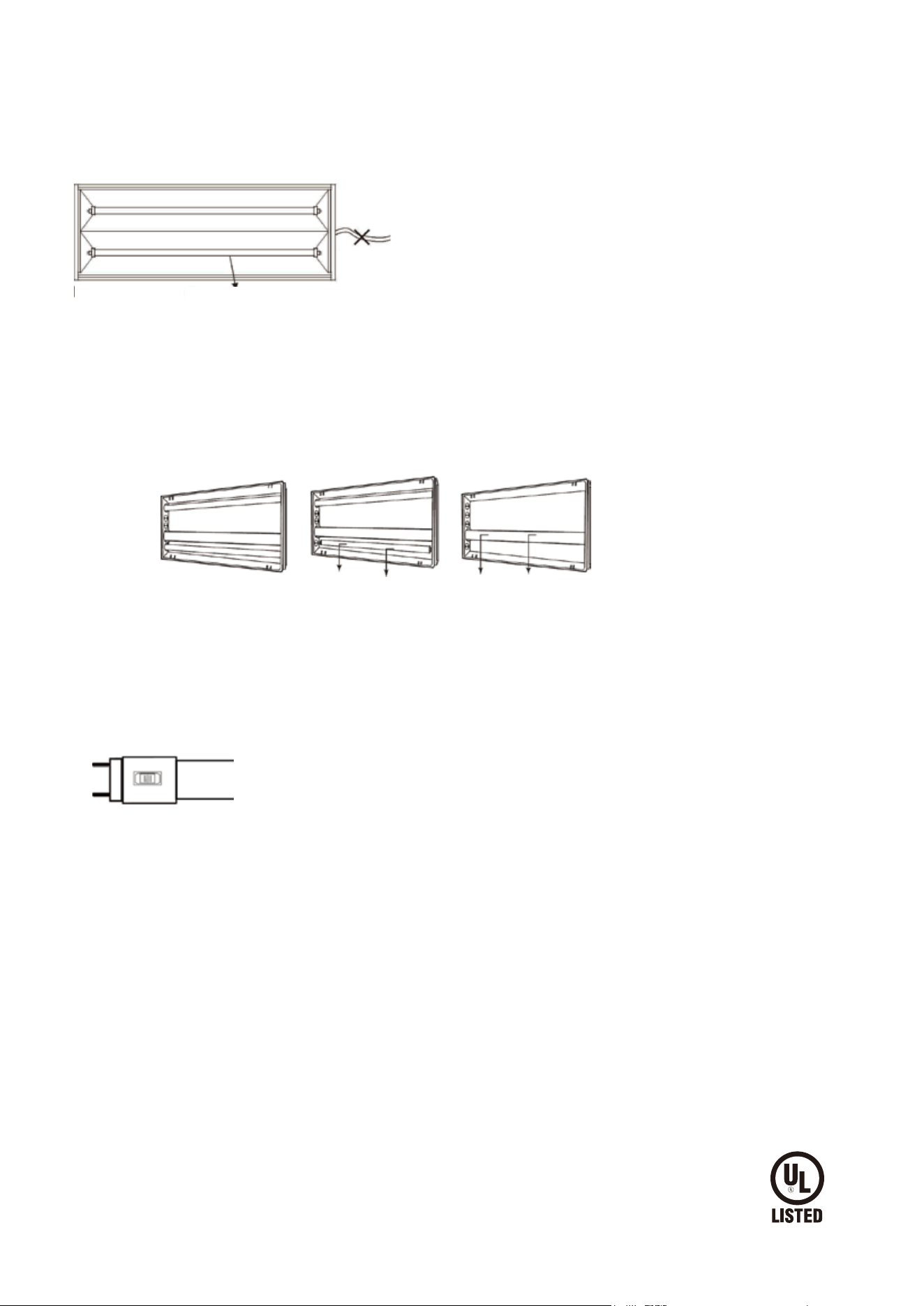
2. REMOVE EXISTING TUBE LAMP(S)
a. Remove troer lens, if present.
b. Remove existing fluorescent by rotating one quarter turn and sliding lamp(s) out of the lamp holders.
c. Remove ballast cover. (Cover may be secured with screws or tabs).
a) Troer and lamps b) Remove tube lamps c) Remove ballast cover (lens removed)
3. RETROFIT LUMINAIRE
Modify the circuit according to the TYPE B wiring diagram.
4. SELECT THE CCT
Select the color temperature through the CCT switch on the LED lamp's base.
• Using the color (CCT) selector switch on the base, select the desired color temperature.
• To prevent damage to lamp, lamp must not be energized when color (CCT) selector switch is changed.
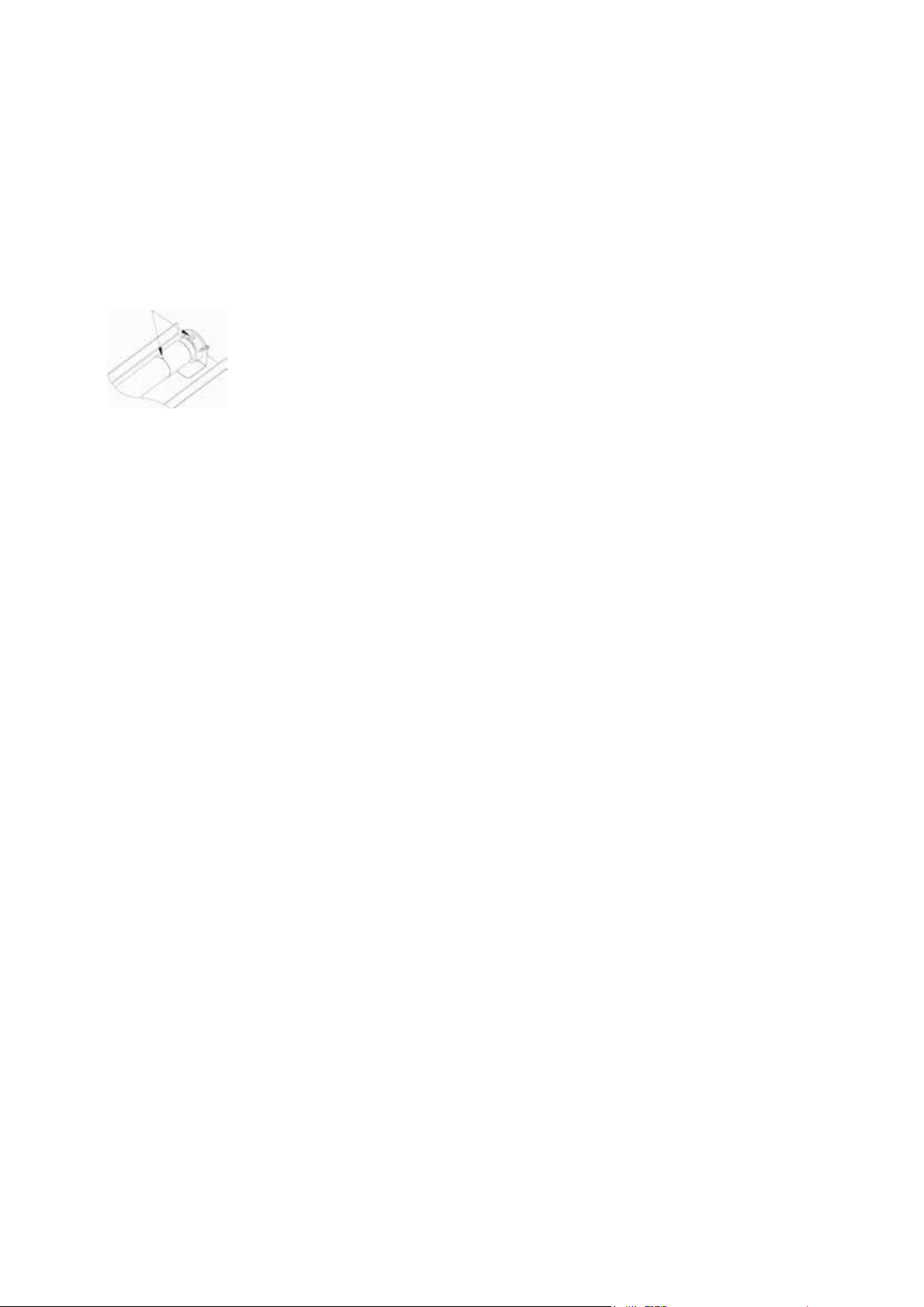
5. INSERT LED TUBES
a. Read label on the LED tube to ensure the power end of LED is aligned with powered tube socket, then insert LED lamp in the
normal way by sliding pins into sockets and rotating a quarter turn until LED tube locks in place.
b. LED lamps are now fully installed.
c. Replace troer lens, if present.
d. After modification is completed. Attach the Replacement Marking and cautionary Label to a visible place on the luminaire
and keep it visible after installation. Be sure to mark the type of wiring on the luminaire label (single or double-ended).
6. RESTORE THE POWER TO THE LUMINAIRE
Restore power to circuit/luminaire and test light. If necessary, adjust position of LED tube, and enjoy your new LED tube light!
7
GUÍA DE INSTALACIÓN
TuboLED T8 TIPOA+B
CCT seleccionable
Instalación directa
PIEZAS/COMPONENTES INCLUIDOS EN EL JUEGO
- Instrucciones de instalación
- Lámpara de tuboLED
- Etiquetas para marcar luminarias. Solo para instalación de tipoB, aplique la siguiente etiqueta de reemplazo de lámpara en
la luminaria de reequipamiento una vez que se haya instalado el juego de reequipamiento, en un lugar fácilmente visible
para el usuario durante el reequipamiento y después de la instalación.
Nota: Este producto cumple con la Parte18 de las normas de la FCC, pero puede causar interferencias en radios, televisores,
teléfonos inalámbricos y mandos a distancia. Si se producen interferencias, aleje el producto de estos dispositivos o
conéctelo a una toma de corriente diferente. No instale este producto cerca de equipos de comunicación de seguridad
marítima ni de otros equipos críticos de comunicación o navegación que funcionen a una frecuencia de 0,45-30MHz.
Aplicación TIPOA (PLUG&PLAY, compatible con balasto)
Para evitar lesiones personales y/o posibles daños al producto, se deben tomar las siguientes precauciones:
• Lea las instrucciones y la información de seguridad en su totalidad antes de la instalación.
• RIESGO DE DESCARGA ELÉCTRICA. Desconecte la alimentación en el fusible o disyuntor antes de realizar la instalación o el mantenimiento.
• Adecuado para lugares húmedos. No debe usarse en lugares expuestos directamente al agua.
• Atención: Utilice únicamente el control proporcionado o especificado en estas instrucciones para controlar esta lámpara. Esta lámpara no
funcionará correctamente si se conecta a un regulador de intensidad o control de regulación de intensidad estándar(incandescente).
• Este dispositivo no se ha diseñado para utilizarse en salidas de emergencia.
• ATENCIÓN: RIESGO DE INCENDIO. UTILIZAR SOLO EN SUSTITUCIÓN DE UNA LÁMPARA FLUORESCENTE
• ¡ATENCIÓN! RIESGO DE INCENDIO: SI LA LÁMPARA O LA LUMINARIA FUNCIONA DE FORMA ANÓMALA (ZUMBIDO, PARPADEO, ETC.),
DESCONECTE INMEDIATAMENTE LA ALIMENTACIÓN, RETIRE LA LÁMPARA DE LA LUMINARIA Y PÓNGASE EN CONTACTO CON EL FABRICANTE.
• ATENCIÓN: RIESGO DE INCENDIO. SI LA LÁMPARA NO SE ILUMINA CUANDO SE CONECTA LA LUMINARIA A LA ALIMENTACIÓN, RETIRE LA
LÁMPARA DE LA LUMINARIA Y PÓNGASE EN CONTACTO CON EL FABRICANTE DE LA LÁMPARA O CON UN ELECTRICISTA CUALIFICADO.
• ATENCIÓN: RIESGO DE INCENDIO O DESCARGA ELÉCTRICA. Al trabajar con balastos electrónicos, consulte primero la lista de
compatibilidad. Si no encuentra su balastro en la lista, realice un bypass en la lámpara como una instalación de tipoB o contacte con
nosotros para obtener ayuda. No instale el tuboLED con un balasto que no esté incluido en la lista de compatibilidad de balastos.
• Para evitar dañar la lámpara, no debe estar conectada a la alimentación cuando se cambie el interruptor selector de color(CCT).
Se debe comprobar la lista de compatibilidad de balastos antes de la instalación.
ADVERTENCIAS
TipoA: diagrama de cableado
TipoA: diagrama de cableado
Guía de instalación tipoA
Nota: El diagrama de cableado debe ser el mismo que el diagrama de cableado del balasto. ¡Al instalar con un balasto, consulte
primero la lista de compatibilidad! ¡Si no encuentra su balastro en la lista, realice un bypass en la lámpara o contacte con
nosotros! No instale el tuboLED con un balasto que no esté incluido en la lista de compatibilidad de balastos.
Balasto
electrónico
Compatible con electrónica (tipoA)
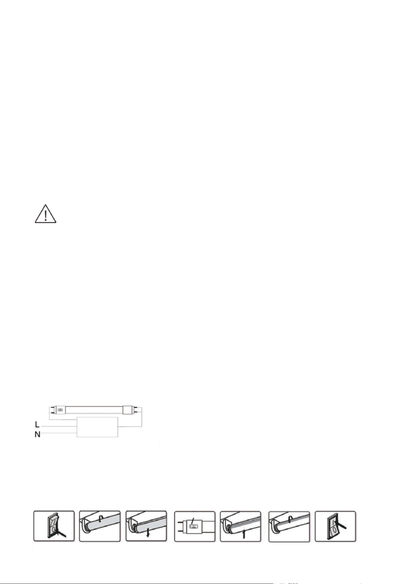
Apagar
Selección CCT
1. Apagar 2. Fluorescente 3. Fluorescente 4. Selección CCT 5.LED T8 6.LED T8 7.Encender
Encender
8
Instalación de derivación de balasto
NOTA: Este equipo ha sido probado y se ha determinado que cumple con los límites para un dispositivo digital de claseB, de
conformidad con la Parte15 de las normas de la FCC. Estos límites están concebidos para ofrecer una protección razonable
contra interferencias perjudiciales en una instalación residencial. Este equipo genera, utiliza y puede irradiar energía de
radiofrecuencia; si no se instala y utiliza de acuerdo con las instrucciones, puede provocar interferencias perjudiciales en
las comunicaciones por radio. En todo caso, no se puede garantizar que no se produzcan interferencias en una instalación
concreta. Si este equipo causa interferencias perjudiciales en la recepción de radio o televisión —lo que se puede determinar
apagando y encendiendo el equipo—, se recomienda al usuario que intente solucionar las interferencias con una o más de
las siguientes medidas:
—Reoriente o reubique la antena receptora.
—Aumente la separación entre el equipo y el receptor.
—Conecte el equipo a una toma de corriente de un circuito diferente a aquel al que está conectado el receptor.
—Consulte al distribuidor o a un técnico de radio/televisión experimentado para obtener ayuda.
Este aparato digital de claseB cumple con la norma canadiense ICES-005.
Para evitar lesiones personales y/o posibles daños al producto, se deben tomar las siguientes precauciones.
• Lea las instrucciones y la información de seguridad en su totalidad antes de la instalación.
• RIESGO DE DESCARGA ELÉCTRICA. Desconecte la alimentación en el fusible o disyuntor antes de realizar la instalación o el
mantenimiento.
• Para evitar dañar la lámpara, no debe estar conectada a la alimentación cuando se cambie el interruptor selector de color(CCT).
• Adecuado para lugares húmedos. No debe usarse en lugares expuestos directamente al agua.
• Atención: Utilice únicamente el control proporcionado o especificado en estas instrucciones para controlar esta lámpara. Esta
lámpara no funcionará correctamente si se conecta a un regulador de intensidad o control de regulación de intensidad estándar
(incandescente).
• Este dispositivo no se ha diseñado para utilizarse en salidas de emergencia.
• Para evitar un fallo prematuro de la lámpara, esta solo debe instalarse en entornos de funcionamiento que oscilen entre
-20°C y +45°C (-4°F y +113°F).
• ADVERTENCIA: RIESGO DE INCENDIO O DESCARGA ELÉCTRICA. La instalación del kit de reequipamientoLED requiere conocimientos
sobre sistemas eléctricos de luminarias. Si no está cualificado, no intente realizar la instalación. Contacte con un electricista
cualificado.
• ADVERTENCIA: RIESGO DE INCENDIO O DESCARGA ELÉCTRICA. Instale este kit únicamente en luminarias que tengan las
características constructivas y las dimensiones que se muestran en las fotografías y/o dibujos y en las que la potencia nominal de
entrada del kit de equipamiento no exceda la potencia nominal de entrada de la luminaria.
• No haga ni modifique ningún orificio en las carcasas protectoras de cableado o de componentes eléctricos durante la instalación del kit.
• ADVERTENCIA: Para evitar daños o abrasión en los cables, no los exponga a los bordes de hojas metálicas ni a otros objetos afilados.
Instrucciones
1. Desconecte la alimentación de la luminaria.
2. Retire el difusor (si está presente).
3. Retire las lámparas fluorescentes existentes de la luminaria.
4. Seleccione la temperatura de color a través del interruptorCCT que hay en la base de la lámparaLED.
• Seleccione la temperatura de color deseada mediante el interruptor selector de color(CCT) que hay en la base.
• Para evitar dañar la lámpara, no debe estar conectada a la alimentación cuando se cambie el interruptor selector de
color(CCT).
5. Instale la lámpara de tuboLED.
Riesgo de incendio: tenga en cuenta que el tubo debe estar bien instalado. Marca en las tapas de los extremos que muestra
la alineación adecuada con los casquillos. Asegúrese de que la marca coincida con el casquillo como se muestra a continu-
ación.
6. Install diuser (if removed in step 2)
7. Switch on power to the luminaire.
8. Before installation, please check specifications for the most current ballast compatibility list, if no match, please insert
led tubes according to below type B installation instructions
ADVERTENCIAS
9
Lista de compatibilidad de reguladores de intensidad de fase inversa
• Los instaladores no deben desconectar los cables de los terminales del casquillo de la lámpara para realizar nuevas conexiones a los
terminales del casquillo de la lámpara. Por el contrario, el instalador deberá cortar los conductores existentes del casquillo de la
lámpara y establecer nuevas conexiones eléctricas a los cables conductores del casquillo de la lámpara utilizando los conectores
adecuados para la aplicación.
• ESTE JUEGO DE REEQUIPAMIENTO SE ACEPTA COMO COMPONENTE DE UNA LUMINARIA SIEMPRE QUE LAS AUTORIDADES COMPETENTES
DETERMINEN LA IDONEIDAD DE LA COMBINACIÓN. EL PRODUCTO DEBE SER INSTALADO POR UN ELECTRICISTA CUALIFICADO DE
ACUERDO CON LOS CÓDIGOS ELÉCTRICOS APLICABLES Y APROPIADOS. LA GUÍA DE INSTALACIÓN NO REEMPLAZA LAS REGULACIONES
LOCALES O NACIONALES PARA INSTALACIONES ELÉCTRICAS.
• Examine todas las piezas que no estén destinadas a ser reemplazadas por el juego de reequipamiento para detectar posibles daños y
reemplace cualquier pieza dañada antes de instalar el juego de reequipamiento.
• El tubo se instala como tipoB; la luminaria, una vez modificada como lámpara de reequipamiento, ya no funcionará con lámparas
fluorescentes.
• Para la conversión de una lámparaLED de tubo lineal, deberá haber disponible un texto o un diagrama que muestre cómo se han
realizado las conexiones de alimentación a los portalámparas, de manera que se realicen las conexiones correctas a la lámpara
cuando esta se instale o reemplace.
OR
OR
OR
Notas importantes:
• Para la instalación de tubos con cableado de un solo extremo, se deben utilizar portalámparas sin derivación.
• Para la instalación con cableado de doble extremo, no es necesario cambiar los casquillos/portalámparas (si se
encuentran en buen estado), independientemente del tipo de casquillos.
Guía de instalación tipoB:
Siga completamente estas instrucciones y notas para garantizar que el producto funcione en condiciones seguras.
Información de seguridad importante: lea todas las instrucciones antes de la instalación.
TipoB: diagrama de cableado
Conecte dos cables al circuito derivado L y N de acuerdo con la siguiente figura.
Caso1: Diagrama de cableado de CA directa sin regulación de intensidad
1. Entrada de alimentación de un solo extremo
Caso2: Diagrama de cableado de CA directa con regulación de intensidad de fase inversa (véase la lista de compatibilidad
de reguladores de intensidad).
Entrada de alimentación de un solo extremo Entrada de alimentación de doble extremo
2. Entrada de alimentación de doble extremo
Tensión de entrada: 120-277V 50/60Hz
Tensión de entrada: 120-277V 50/60Hz
Tensión de entrada: 120-277V 50/60Hz
MARCA
NÚMERO DE MODELO
MARCA
NÚMERO DE MODELO
LUTRON
DVELV-300P-BR
LUTRON
DVELV-303P-WH
LUTRON
DVELV-300P-GR
LUTRON
MAELV-600-AL
LUTRON
DVELV-300P-IV
LUTRON
MAELV-600-BL
LUTRON
DVELV-300P-LA
LUTRON
MAELV-600-BR
LUTRON
DVELV-300P-WH
LUTRON
MAELV-600-GR
LUTRON
DVELV-303P-BR
LUTRON
MAELV-600-IV
LUTRON
DVELV-303P-GR
LUTRON
MAELV-600-LA
LUTRON
DVELV-303P-IV
LUTRON
MAELV-600-WH
LUTRON
DVELV-303P-LA
Phase cut
dimmer
Notas importantes:
• Para la instalación de tubos con cableado de un solo extremo, se deben utilizar portalámparas sin derivación.
• Para la instalación con cableado de doble extremo, no es necesario cambiar los casquillos/portalámparas (si se
encuentran en buen estado), independientemente del tipo de casquillos.
Regulador de intensidad
de corte de fase
Regulador de intensidad
de corte de fase
10
2. RETIRADA DE LA LÁMPARA O LÁMPARAS EXISTENTES
a. Retire la pantalla de la luminaria empotrada (si está presente).
b. Retire los fluorescentes existentes girándolos un cuarto de vuelta y deslizando la lámpara o lámparas para sacarlas de
los portalámparas.
c. Retire la cubierta del balasto (puede que la cubierta esté asegurada con tornillos o lengüetas).
a) Luminaria empotrada y
lámparas de tubo.
b) Retire las lámparas de tubo. c) Retire la cubierta del balasto
(pantalla retirada).
3. REEQUIPAMIENTO DE LUMINARIA
Modifique el circuito de acuerdo con el diagrama de cableado TIPOB.
4. SELECCIÓN DE CCT
Seleccione la temperatura de color a través del interruptorCCT que hay en la base de la lámparaLED.
• Seleccione la temperatura de color deseada mediante el interruptor selector de color(CCT) que hay en la base.
• Para evitar dañar la lámpara, no debe estar conectada a la alimentación cuando se cambie el interruptor selector de
color(CCT).
5. INSERCIÓN DE LOS TUBOSLED
a. Lea la etiqueta del tuboLED para asegurarse de que el extremo de alimentación del LED esté alineado con el casquillo del
tubo que recibe alimentación. A continuación, inserte la lámparaLED de la manera habitual, deslizando las clavijas en los
casquillos y girando un cuarto de vuelta hasta que el tuboLED quede bloqueado en su lugar.
b. Las lámparasLED están ahora completamente instaladas.
c. Vuelva a colocar la pantalla de la luminaria empotrada (si estaba presente).
d. Una vez completada la modificación. Coloque la marca de reemplazo y la etiqueta de precaución en un lugar visible de la
luminaria y asegúrese de que se mantengan visibles después de la instalación. Asegúrese de marcar el tipo de cableado
en la etiqueta de la luminaria (de un solo extremo o de doble extremo).
6. RESTABLECIMIENTO DE LA ALIMENTACIÓN DE LA LUMINARIA
Restablezca la alimentación del circuito/luminaria y pruebe la luz. Si es necesario, ajuste la posición del tuboLED. ¡Disfrute
de su nueva lámpara de tuboLED!
Guía de instalación tipoB:
Siga completamente estas instrucciones y notas para garantizar que el producto funcione en condiciones seguras.
Información de seguridad importante: lea todas las instrucciones antes de la instalación.
Instrucciones
1. Desconecte la alimentación.
Desconecte la alimentación de la luminaria o circuito (si es posible). Asegúrese de que toda la alimentación esté desconect-
ada utilizando un voltímetro u otro método de confirmación.
Desconexión de la alimentación
Luminaria Fluorescente que va a reemplazarse
