WHEEL KIT
WHEEL KIT INSTALLATION
NOTICE
Assembling the generator will require lifting the unit on one
side. Install the mounting feet and wheel before adding
fuel or oil.
CAUTION
Weight hazard. Always have assistance when lifting the
generator.
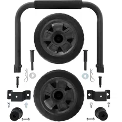
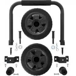
CARTON CONTENTS
Item Quantity
Mounting Feet
• Foot bracket 2
• Shock mount 2
• Bolt, M6x28 2
• Lock nut, M6 2
• Bolt, M8 4
Wheels
• Wheel 2
• Axle pin 2
• Washer 2
• Cotter pin 2
Handle
• Handle 1
• Handle pad 1
• Bolt, M10 2
• Handle cap 2
If any parts are missing, contact our service team at
[email protected] or call 1-855-944-3571.
1. Place generator on a at surface.
2. Assemble the mounting feet as shown.
Bolt, M6
Shock mount
Foot bracket
Lock nut
3. Tip the generator on a piece of cardboard or other soft
material to protect the frame paint and prevent the
generator from sliding.
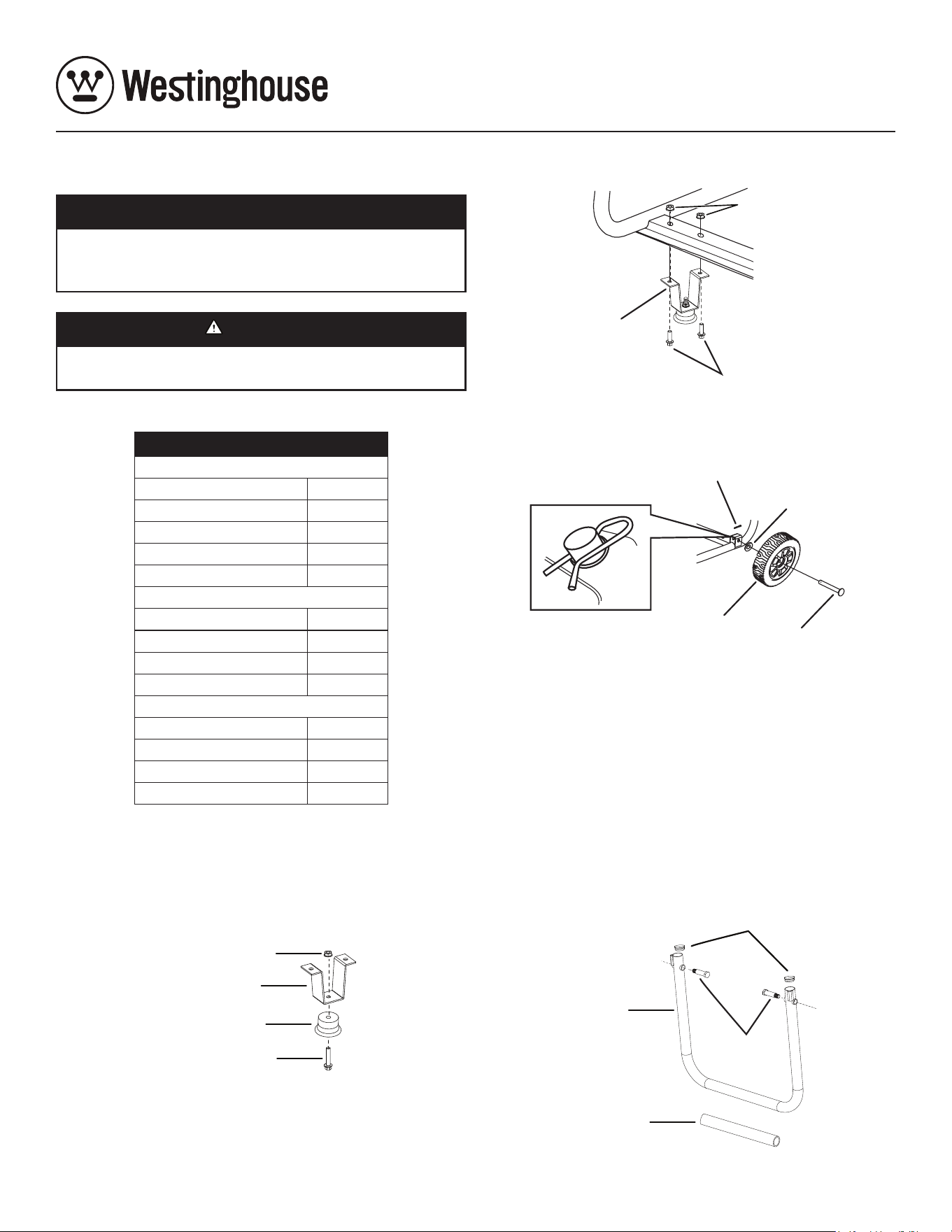
4. Install the mounting feet to the frame as shown.
Mounting foot
Bolt, M8
Lock nut
5. Install the wheels as shown with the anged side of the
wheel toward the generator.
Axle pin
Wheel
Cotter pin
Washer
Note: The wheels are only intended for hand transport. The
wheels are not suitable for towing the generator either
on or off-road.
6. Install the handle pad on the handle. Use rubbing alcohol
as a lubricant to ease installation. Spray inside the pad
and on the handle and slide the pad onto the handle.
Note: Wait for the alcohol to evaporate before using the
handle to transport the generator. This may take
several hours.
7. Install the handle to the frame as shown.
Handle pad
Bolt, M10
Handle
Handle cap
AC3600v-1 Rev 01