SKU/Model: # xxx /SW20006 ORB
# xxx /SW20006 MBK
# xxx /SW20006 BN
CLARET
TBA
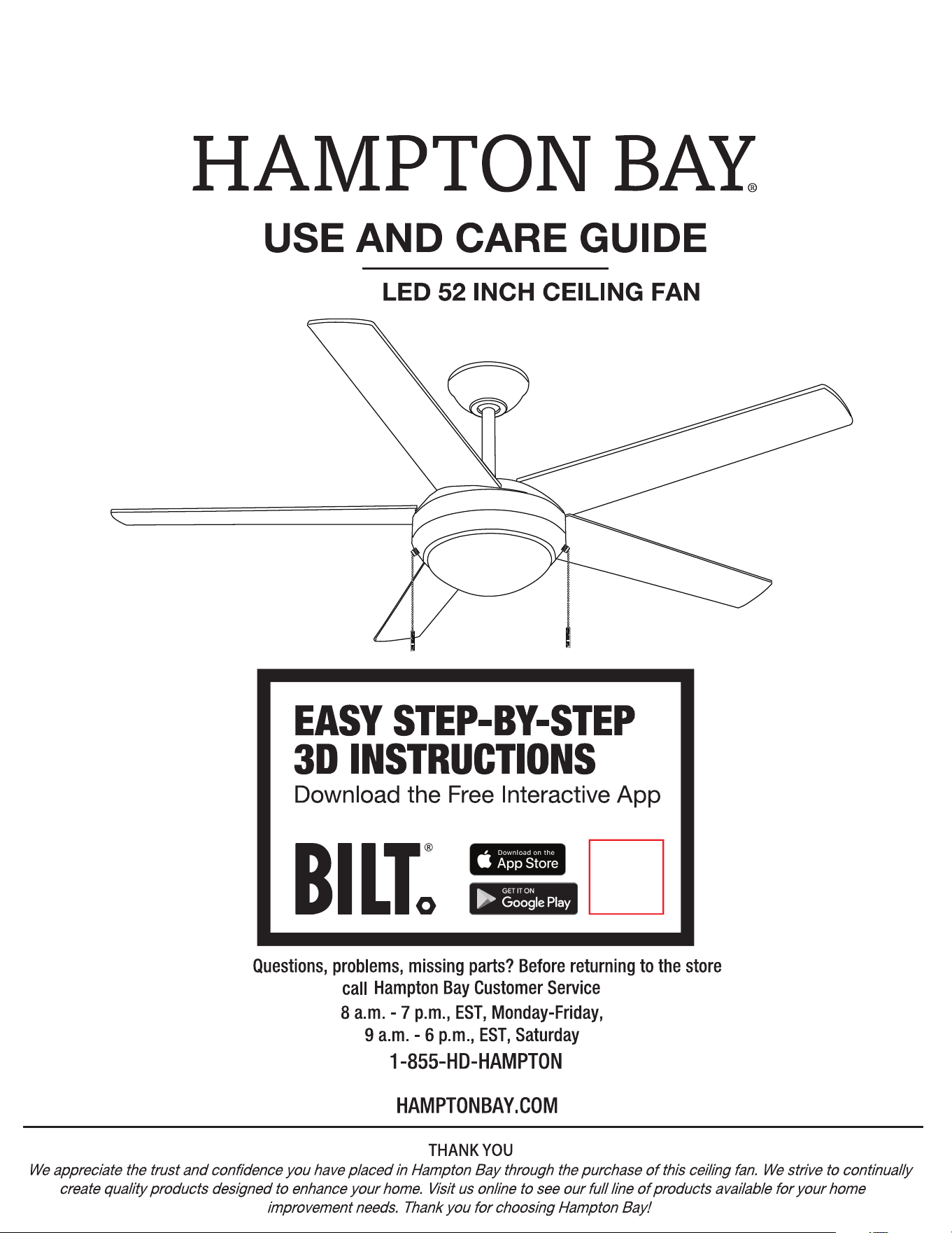
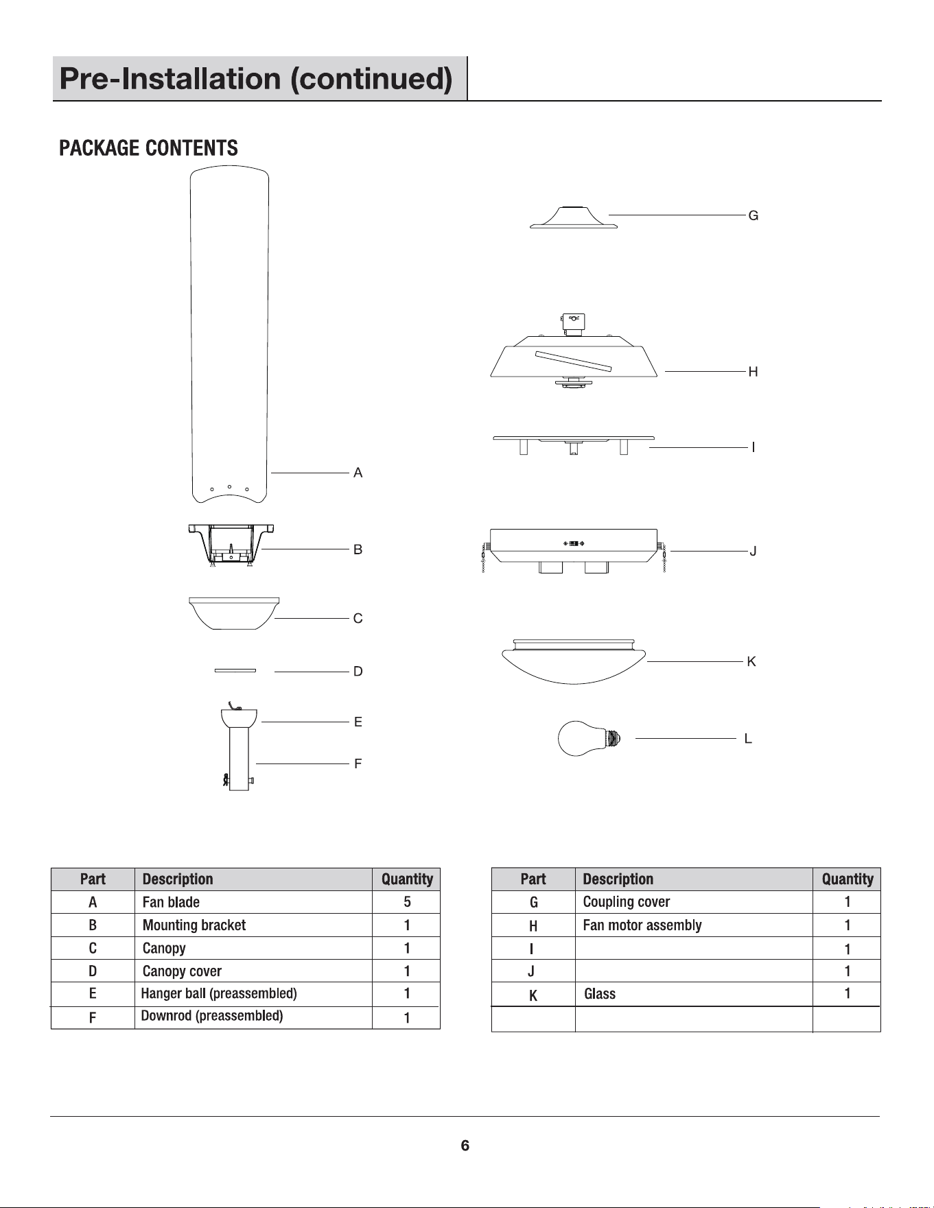
READ AND SAVE THESE INSTRUCTIONS.
52 in.
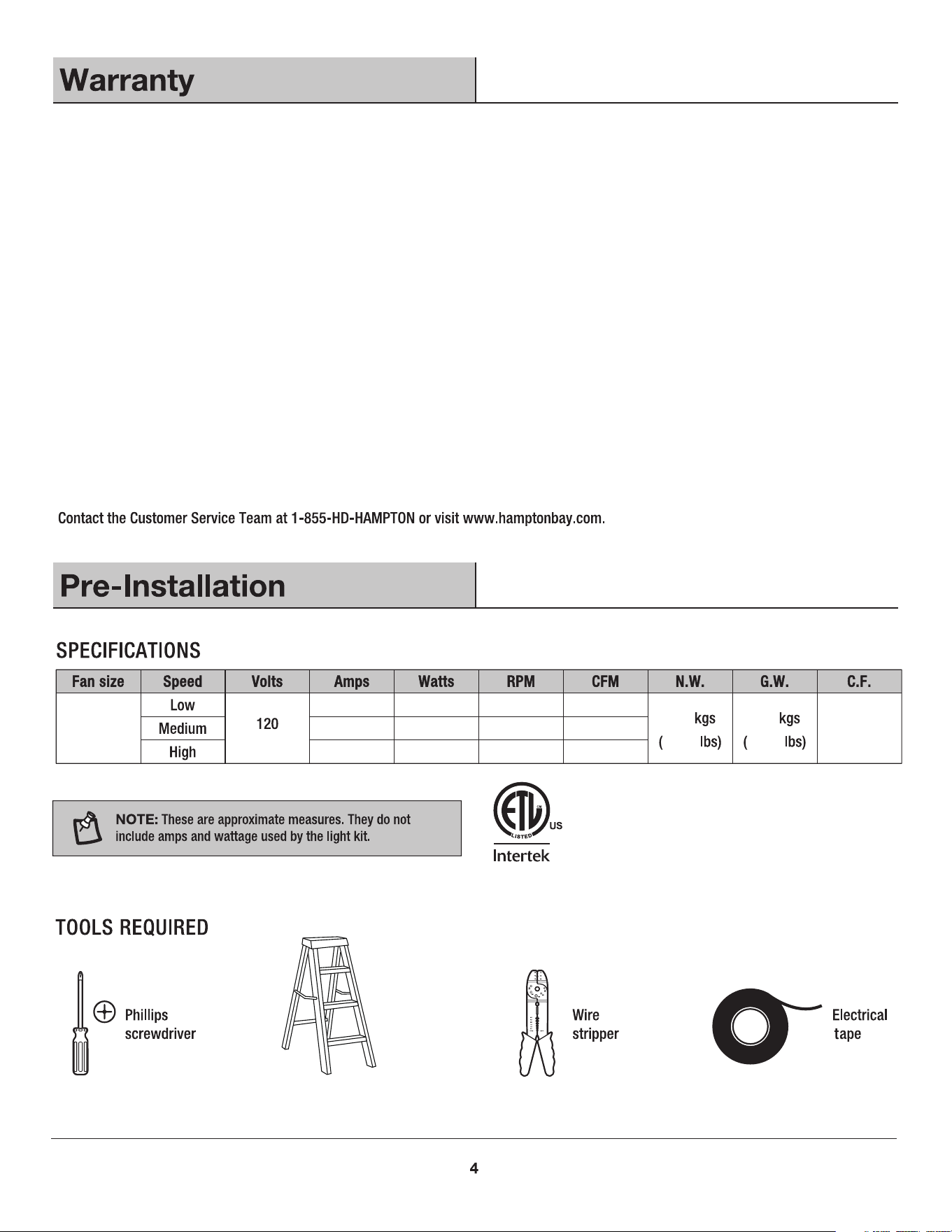
0.25 13.55 76 1868
0.38 30.51 121 3037
0.53 63.66 170 4549
8.1
10.17
17.82 22.37
1.551’
We warrant the fan motor to be free from defects in workmanship and material present at time of shipment from the factory for a period
of lifetime after the date of purchase by the original purchaser. And we warrant the LED light kit to be free from defects in workmanship
and material present at time of shipment from the factory for a period of 3 years after the date of purchase by the original purchaser.
We also warrant that all other fan parts, excluding any glass or acrylic blades, to be free from defects in workmanship and material at the
time of shipment from the factory for a period of one year after the date of purchase by the original purchaser. We agree to correct such
defects without charge or at our option replace with a comparable or superior model if the product is returned. To obtain warranty service,
you must present a copy of the receipt as proof of purchase. All costs of removing and reinstalling the product are your responsibility.
Damage to any part such as by accident, misuse, improper installation or by affixing any accessories, is not covered by this warranty.
Because of varying climatic conditions this warranty does not cover any changes in brass finish, including rusting, pitting, corroding,
tarnishing or peeling. Brass finishes of this type give their longest useful life when protected from varying weather conditions. A certain
amount of "wobble" is normal and should not be considered a defect. Servicing performed by unauthorized persons shall render the
warranty invalid. There is no other express warranty. We hereby disclaim any and all warranties, including but not limited to those of
merchantability and fitness for a particular purpose to the extent permitted by law. The duration of any implied warranty which cannot be
disclaimed is limited to the time period as specified in the express warranty. Some states do not allow limitation on how long an implied
warranty lasts, so the above limitation may not apply to you. The retailer shall not be liable for incidental, consequential, or special
damages arising out of or in connection with product use or performance except as may otherwise be accorded by law. Some states do
not allow the exclusion of incidental or consequential damages, so the above exclusion or limitation may not apply to you. This warranty
givesd specific legal rights, and you may also have other rights which vary from state to state. This warranty supersedes all prior
warranties. Shipping costs for any return of product as part of a claim on the warranty must be paid by the customer.
Ladder
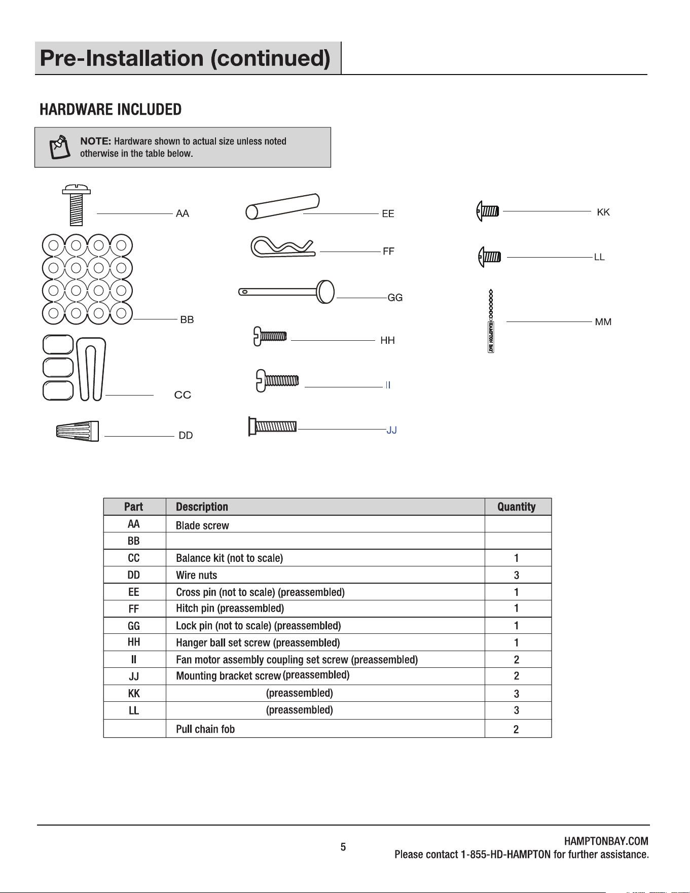
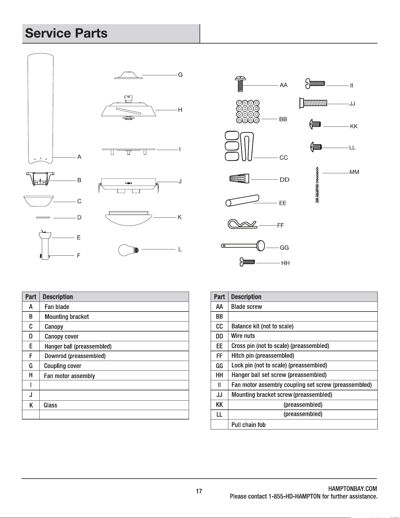
MM
Fiber washer
Locking plate screw
15+1 spare
15+1 spare
Light kit plate screw
L 2
9W LED bulb
Light kit plate
Mounting plate

FF
II
FF
GG
EE
GG
HH
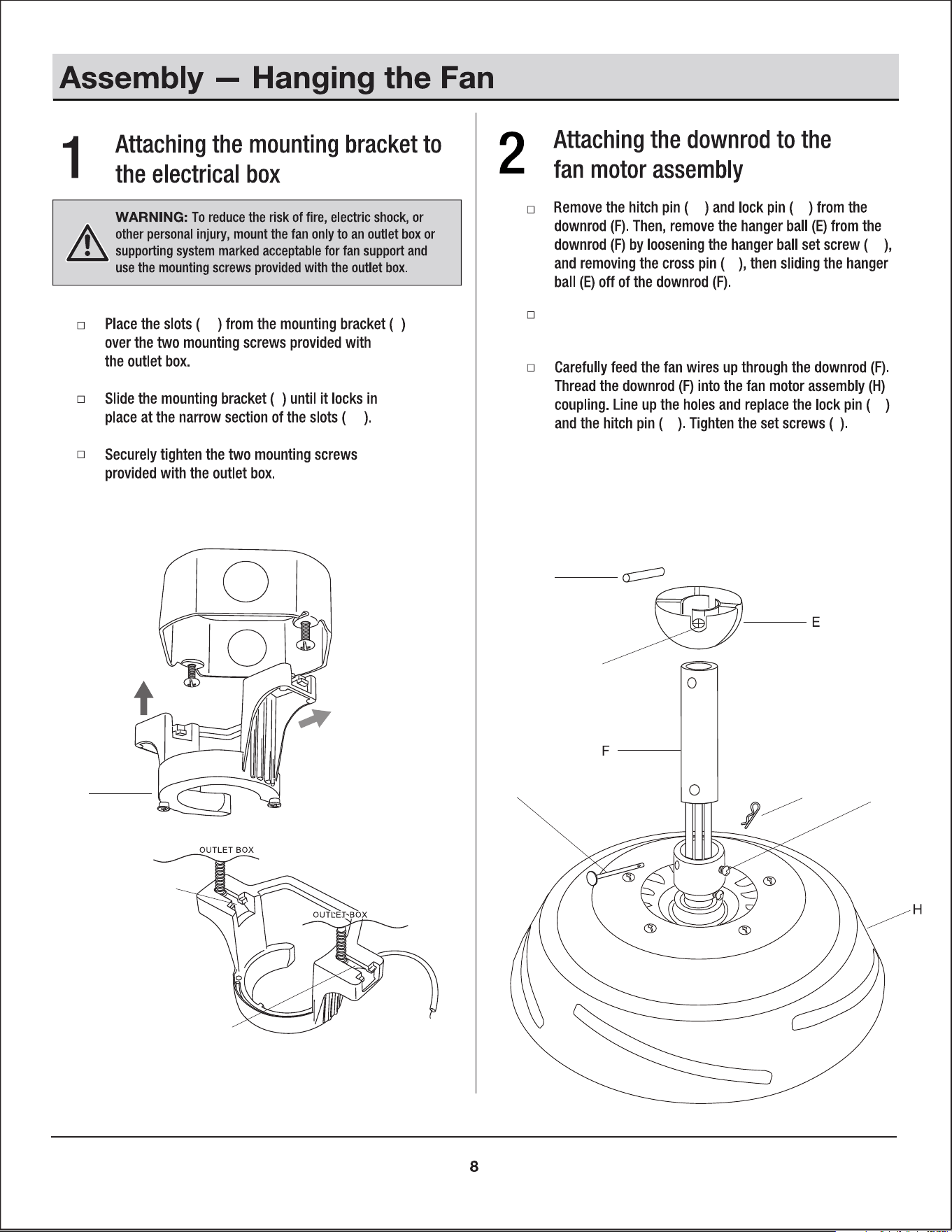
Loosen the two set
screws (II) from the coupling of the
fan motor assembly (H)
B
NN
NN
B
B
NN
NN
EE
HH
GG
FF
II
OO
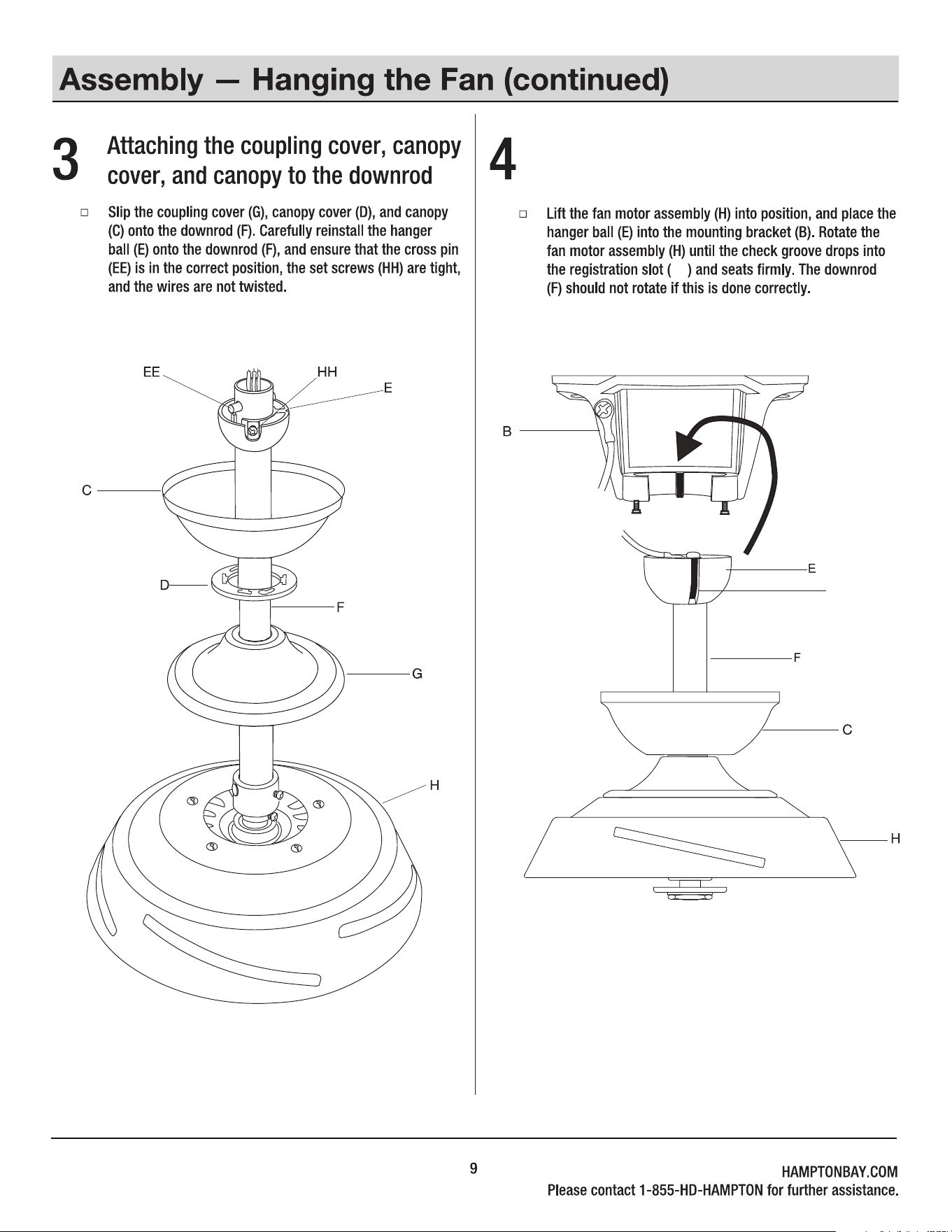
Hanging the fan motor assembly
to the mounting bracket
OO
the
the
the
E
B
in
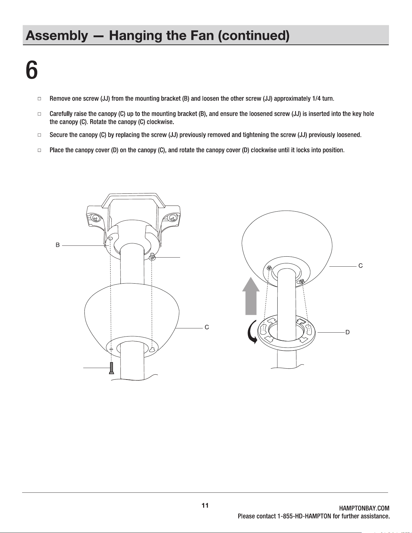
Installing the canopy and canopy cover
JJ
JJ
AA
H
KK
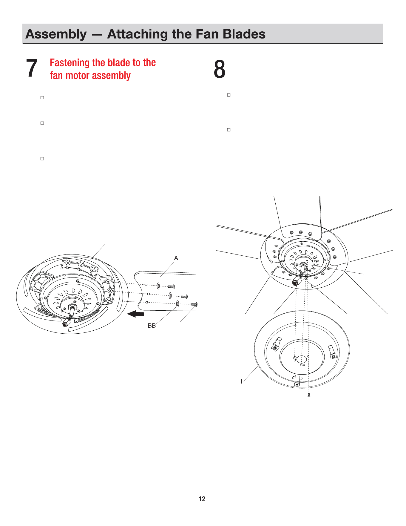
Insert the blade (A) through the slot on the fan
motor assembly (H).
Attach the fan blade (A) to the fan motor assembly
(H) using the three blade screws (AA) and the three
fiber washers (BB) and tighten them securely.
Repeat this step for the other four blades (A).
Installing the mounting plate to the
fan motor assembly
Remove one of the screws (KK) from the locking
plate of the fan motor assembly (H) and loosen the
other two screws (KK), but do not remove.
Place the key holes
from the
mounting plate (I) over the
two screws (KK) previously loosened from the fan
motor assembly (H). Turn the mounting plate (I) until
it locks at the narrow section of the key holes.
Secure by tightening the two screws (KK) previously
loosened and the one screw (KK) previously removed.
H
10
J
L
PP
LL
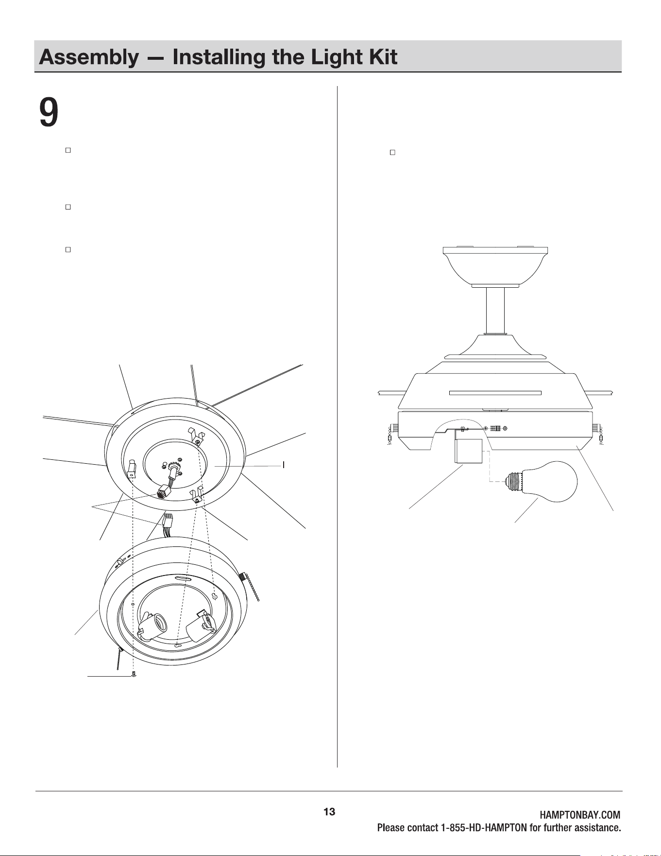
Attaching the light kit plate to
the mounting plate
Remove one of the screws (LL) from the mounting
plate (I) and loosen the other two screws (LL), but
do not remove.
While holding the light kit plate (J) under your fan,
firmly snap the wire connection
plugs
(PP) together.
Place the key holes
from the
light kit plate (J) over the
two screws (LL) previously loosened from the
mounting plate (I).Turn the light kit plate (J) until it
locks at the narrow section of the key holes.
Secure by tightening the two screws (LL) previously
loosened and the one screw (LL) previously removed.
Install the two 9W LED bulbs (L) into the
sockets (QQ).
J
QQ
Installing the LED bulbs
11
K
MM
J
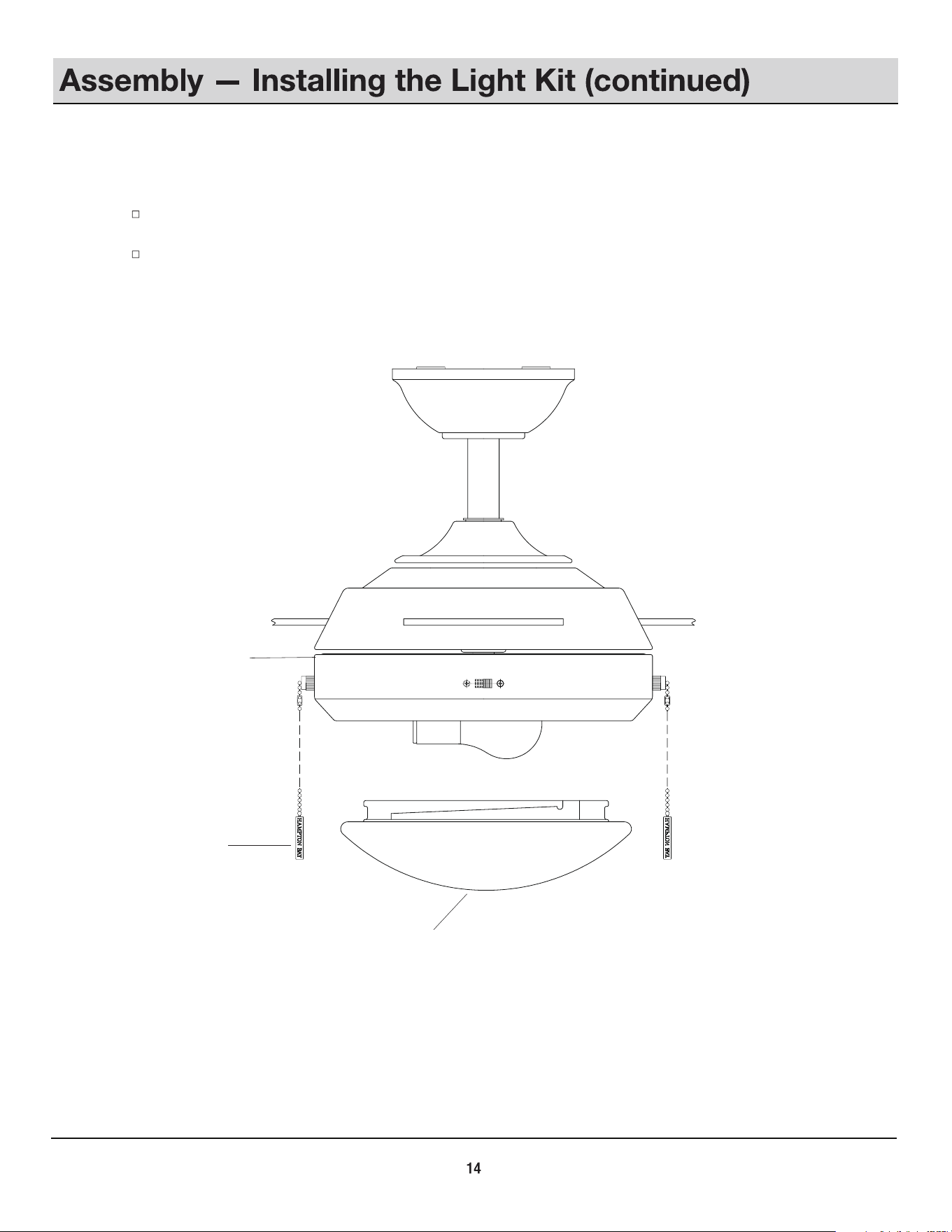
Installing the glass and pull chain fob
Attach the glass (K) to the light kit plate (J) by twisting tightly. (DO NOT OVERTIGHTEN)
Attach the pull chain fob (MM) to the chain on the light kit plate (J).
J
SS
RR
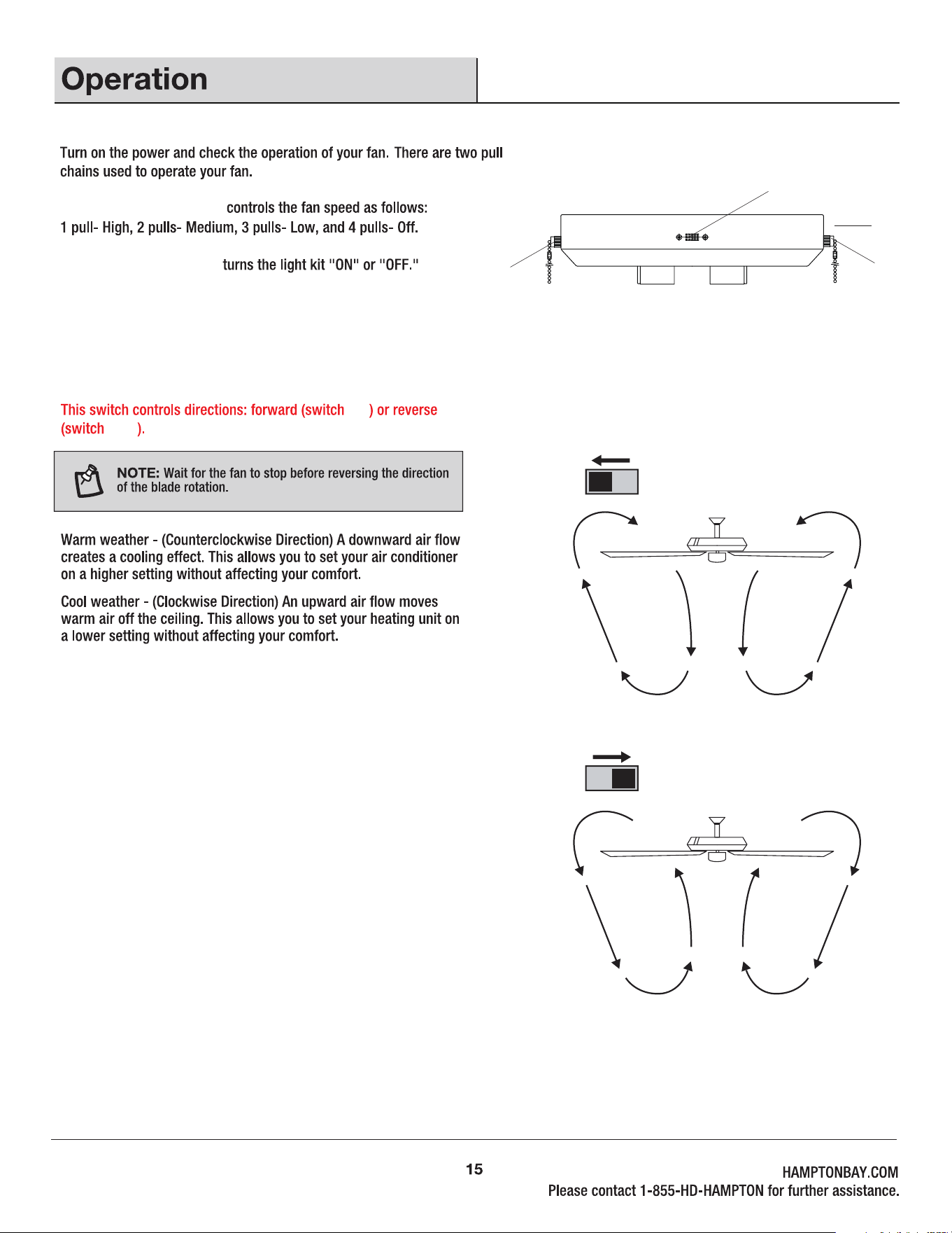
The 3-speed pull chain (SS)
TT
Reverse Function
The light kit pull chain (TT)
The reverse switch (RR) is located on the surface of the light kit
plate (J).
left
right
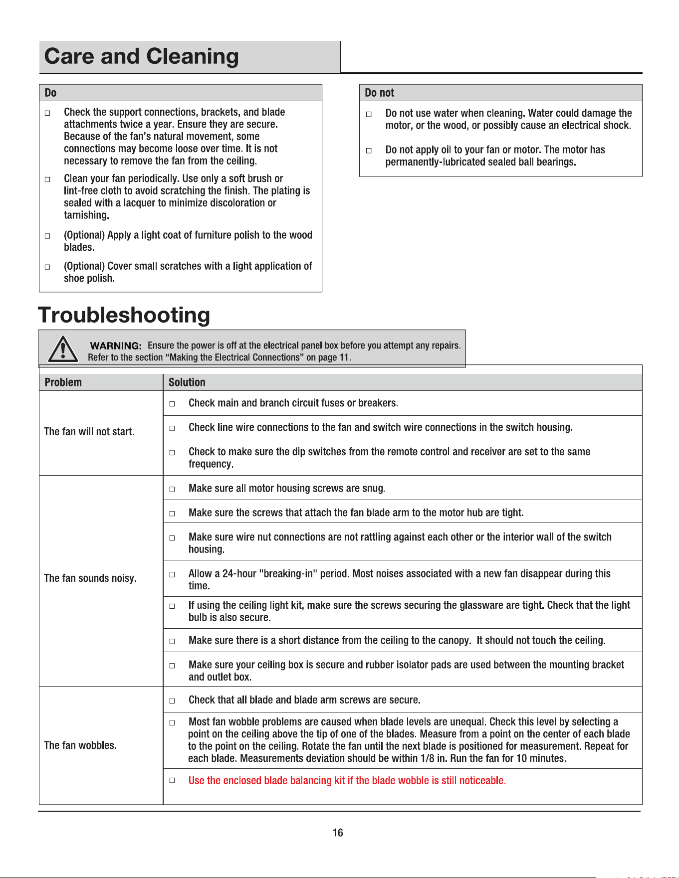
Balancing kit includes an
additional instruction manual within the packet.
L
9W LED bulb
MM
Locking plate screw
Locking plate screw
Fiber washer
Light kit plate
Mounting plate
CF552KP-02
HAMPTON BAY