

Form No. 3468-829 Rev A
Power Max
®
724 OE Snowthrower
Model No. 37807 —Serial No. 400000000 and Up
Register at www .T oro.com.
Original Instructions (EN)
*3468-829*
Important: If you are using this machine above
1500 m (5,000 ft) for a continuous period, ensure
that the High Altitude Kit has been installed
so that the engine meets CARB/EP A emission
regulations. The High Altitude Kit increases
engine performance while preventing spark-plug
fouling, hard starting, and increased emissions.
Once you have installed the kit, attach the
high-altitude label next to the serial decal on the
machine. Contact any Authorized T oro Service
Dealer to obtain the proper High Altitude Kit and
high-altitude label for your machine. T o locate
a dealer convenient to you, access our website
at www .T oro.com or contact our T oro Customer
Care Department at the number(s) listed in your
Emission Control W arranty Statement. Remove
the kit from the engine and restore the engine to
its original factory conguration when running the
engine under 1500 m (5,000 ft). Do not operate an
engine that has been converted for high-altitude
use at lower altitudes; otherwise, you could
overheat and damage the engine.
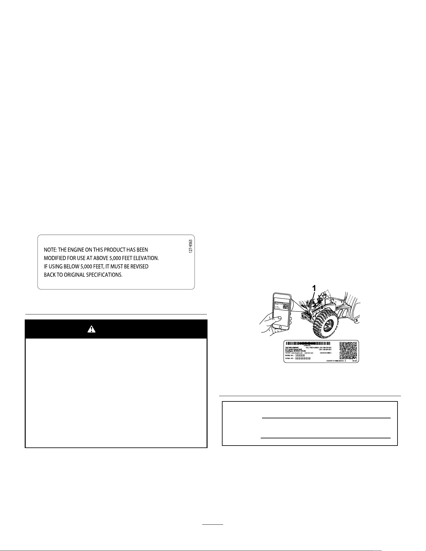
If you are unsure whether or not your machine has
been converted for high-altitude use, look for the
following label ( Figure 3 ).
decal127-9363
Figure 3
W ARNING
CALIFORNIA
Proposition 65 W arning
The engine exhaust from this product
contains chemicals known to the State of
California to cause cancer , birth defects,
or other reproductive harm.
Use of this product may cause exposure
to chemicals known to the State of
California to cause cancer , birth defects,
or other reproductive harm.
Introduction
This machine is intended to be used by residential
homeowners. It is designed primarily for removing
snow from paved surfaces, such as driveways and
sidewalks, and other surfaces for traf c on residential
or commercial properties. It is not designed for
removing materials other than snow . Using this
product for purposes other than its intended use could
prove dangerous to you and bystanders.
Read this information carefully to learn how to operate
and maintain your product properly and to avoid
injury and product damage. Y ou are responsible for
operating the product properly and safely .
V isit www .T oro.com for product safety and operation
training materials, accessory information, help nding
a dealer , or to register your product.
Whenever you need service, genuine T oro parts, or
additional information, contact an Authorized Service
Dealer or T oro Customer Service and have the model
and serial numbers of your product ready . Figure 1
identies the location of the model and serial numbers
on the product. W rite the numbers in the space
provided.
Important: W ith your mobile device, you can
scan the QR code on the serial number decal (if
equipped) to access warranty , parts, and other
product information.
g293068
Figure 1
1. Model and serial number location
Model No.
Serial No.
© 2024—The T oro® Company
81 1 1 L yndale A venue South
Bloomington, MN 55420
2
Contact us at www .T oro.com.
Printed in Mexico
All Rights Reserved

Safety-Alert Symbol
The safety-alert symbol ( Figure 2 ) shown in this
manual and on the machine identies important safety
messages that you must follow to prevent accidents.
g000502
Figure 2
Safety-alert symbol
The safety-alert symbol appears above information
that alerts you to unsafe actions or situations and
is followed by the word DANGER , W ARNING , or
CAUTION .
DANGER indicates an imminently hazardous situation
which, if not avoided, will result in death or serious
injury .
W ARNING indicates a potentially hazardous situation
which, if not avoided, could result in death or serious
injury .
CAUTION indicates a potentially hazardous situation
which, if not avoided, may result in minor or moderate
injury .
This manual uses two other words to highlight
information. Important calls attention to special
mechanical information and Note emphasizes general
information worthy of special attention.
Safety
General Safety
This product is capable of amputating hands and
feet and of throwing objects. Always follow all safety
instructions to avoid serious personal injury .
• Read and understand the contents of this
Operator ’ s Manual before you start the engine.
Ensure that everyone using this product knows
how to use it, knows how to shut of f the engine
quickly , and understands the warnings.
• Shut of f the engine whenever you leave the
operating position for any reason.
• Do not put your hands or feet near moving parts
on the machine.
• Do not operate the machine without all guards
and other safety protective devices in place and
working.
• Keep clear of any discharge opening. Keep
bystanders, especially small children, out of the
operating area.
• Never allow children to operate the machine.
3
Safety and Instructional Decals
Safety decals and instructions are easily visible to the operator and are located near any area
of potential danger . Replace any decal that is damaged or missing.
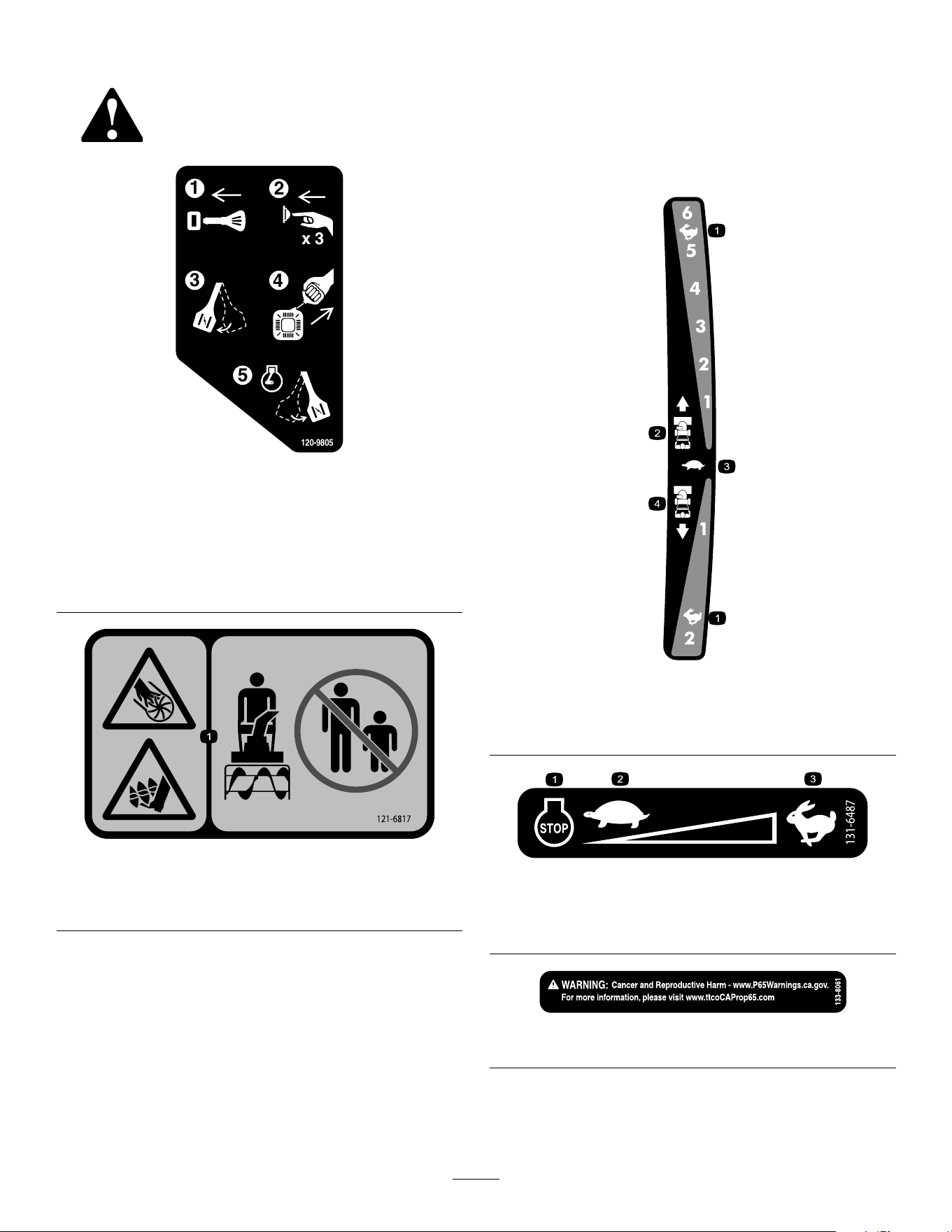
x 3
1
2
3
4
5
120-9805
decal120-9805
120-9805
1. Insert the key .
2. Prime the engine 3 times.
3. Engage the choke.
4. Pull the starter cord.
5. Once the engine is running, disengage the choke.
decal121-6817
121-6817
1. Cutting/dismemberment hazard of hand or foot, impeller
and auger—keep bystanders away .
Order Part No. 138-8487
decal121-6823
121-6823
1. Fast
3. Slow
2. Forward speeds 4. Reverse speeds
decal131-6487
131-6487
1. Engine—shut of f
3. Fast
2. Slow
decal133-8061
133-8061
4
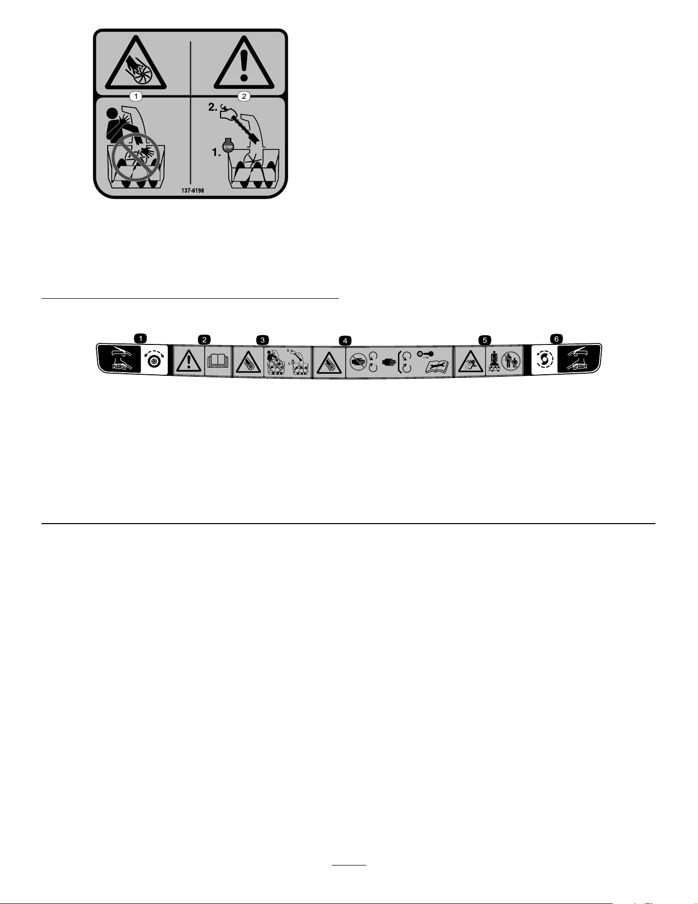
decal137-6198
137-6198
1. Cutting/dismemberment
hazard of the ngers or
hand, impeller—do not
place your hand in the
chute.
2. W arning—shut of f the
engine before using the
tool to clear the chute.
Order Part No. 138-8487
decal121-1240
121-1240
1. T raction drive—squeeze the lever to engage; release the
lever to disengage.
4. Cutting/dismemberment hazard of hand, impeller—stay away
from moving parts; keep all guards and shields in place;
remove the key and read the Operator ’ s Manual before
performing maintenance.
2. W arning—read the Operator ’ s Manual .
5. Thrown object hazard—keep bystanders away .
3. Cutting/dismemberment hazard of hand, impeller—do not
place your hand in the chute; shut of f the engine before
leaving the operating position; use the tool to clear the chute.
6. Auger/impeller drive—squeeze the lever to engage; release
the lever to disengage.
5
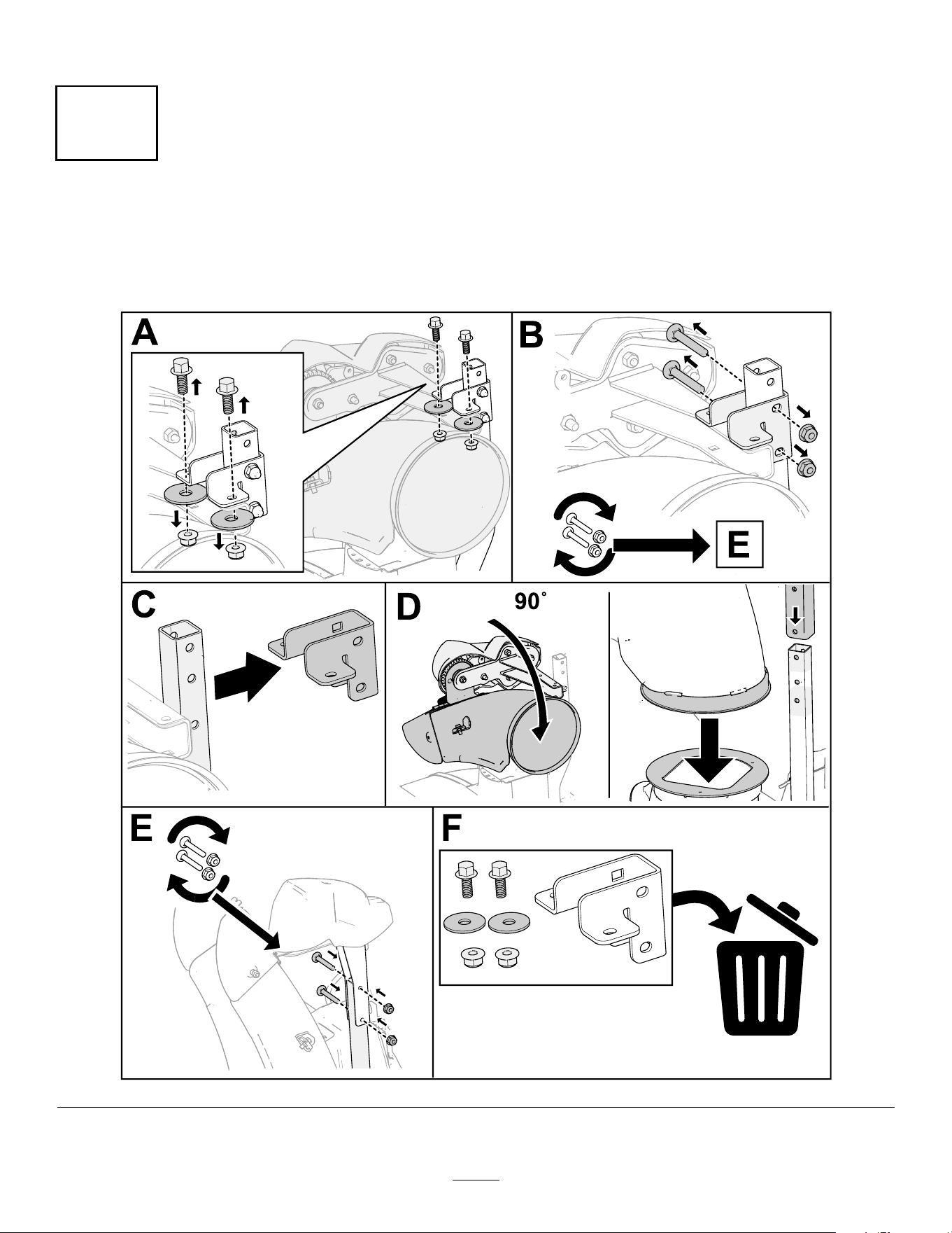
Setup
1
Installing the Chute
No Parts Required
Procedure
g385316
6
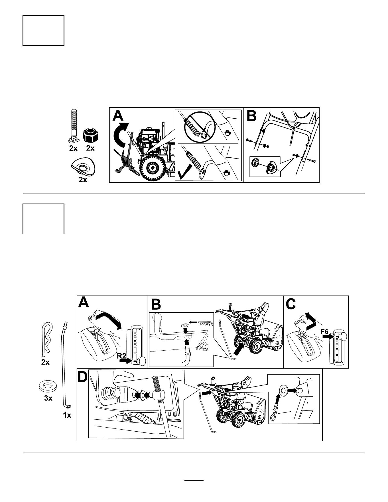
2
Installing the Upper Handle
No Parts Required
Procedure
g263892
3
Installing the T raction-Control Linkage
No Parts Required
Procedure
g252391
7
4
Installing the Chute-Control Rod
No Parts Required
Procedure
g257848
8
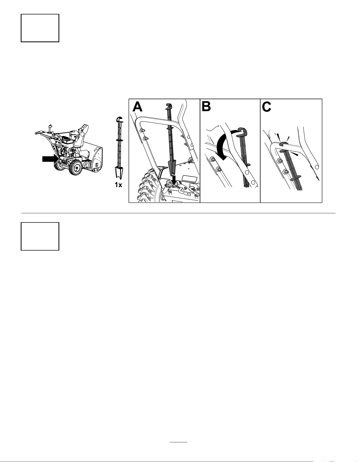
5
Installing the Snow-Cleanout T ool
No Parts Required
Procedure
g252394
6
Checking the Engine-Oil Level
No Parts Required
Procedure
Note: Y our machine comes with oil in the engine crankcase. Before starting the engine, check the oil level
and add oil if necessary .
Refer to Checking the Engine-Oil Level ( page 20 ) .
9
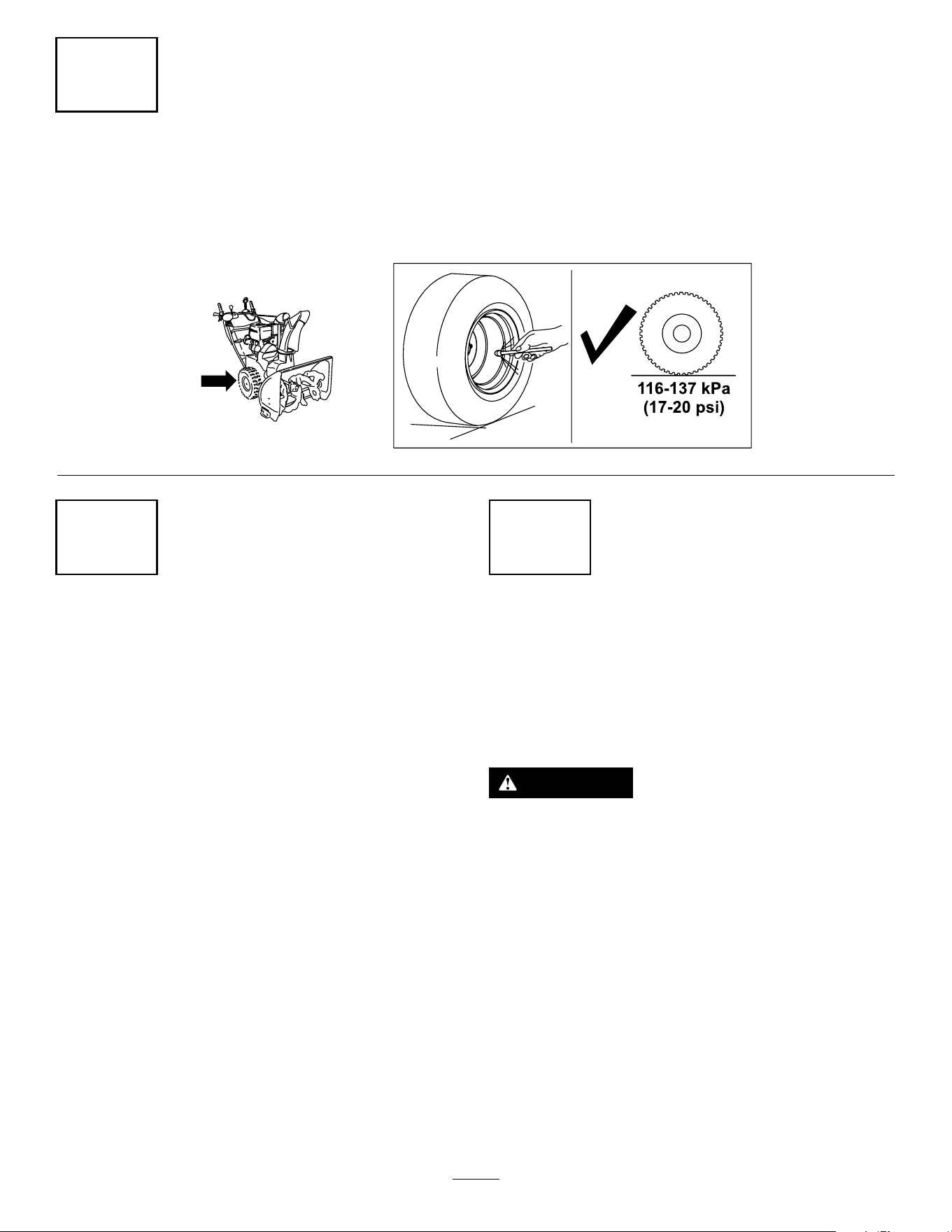
7
Checking the T ire Pressure
No Parts Required
Procedure
g252396
8
Checking the Skids and
Scraper
No Parts Required
Procedure
Refer to Checking and Adjusting the Skids and
Scraper ( page 20 ) .
9
Checking the Operation of
the T raction Drive
No Parts Required
Procedure
CAUTION
If the traction drive is not properly adjusted,
the machine may move in the direction
opposite of what you intended, causing injury
and/or property damage.
Carefully check the traction drive and adjust it
properly , if necessary .
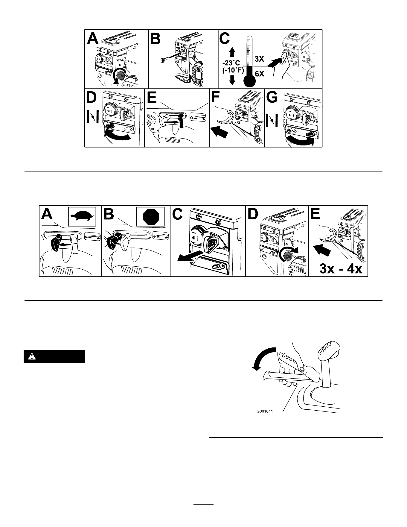
1. Start the engine; refer to Starting the Engine
( page 14 ) .
2. Move the speed selector to Position R1; refer to
Operating the Speed Selector ( page 16 ) .
3. Squeeze the left (traction) lever to the handgrip
( Figure 10 ).
10
g00101 1
Figure 10
The machine should move rearward. If the
machine does not move or moves forward,
complete the following:
A. Release the traction lever and shut of f the
engine.
B. Disconnect the trunnion from the
speed-selector lever .
C. T urn the trunnion downward (clockwise) on
the speed-control rod.
D. Connect the trunnion to the speed-selector
lever .
4. Release the traction lever .
5. Move the speed selector to Position 1; refer to
Operating the Speed Selector ( page 16 ) .
6. Squeeze the left (traction) lever to the handgrip
( Figure 10 ).
The machine should move forward. If the
machine does not move or moves rearward,
complete the following:
A. Release the traction lever and shut of f the
engine.
B. Disconnect the trunnion from the
speed-selector lever .
C. T urn the trunnion upward (counterclockwise)
on the speed-control rod.
D. Connect the trunnion to the speed-selector
lever .
7. If you made any adjustments, repeat this
procedure until no adjustments are required.
Important: If the machine moves when the
traction lever is in the released position, check the
traction cable; refer to Checking and Adjusting
the T raction Cable ( page 20 ) or take the machine
to an Authorized Service Dealer for service.
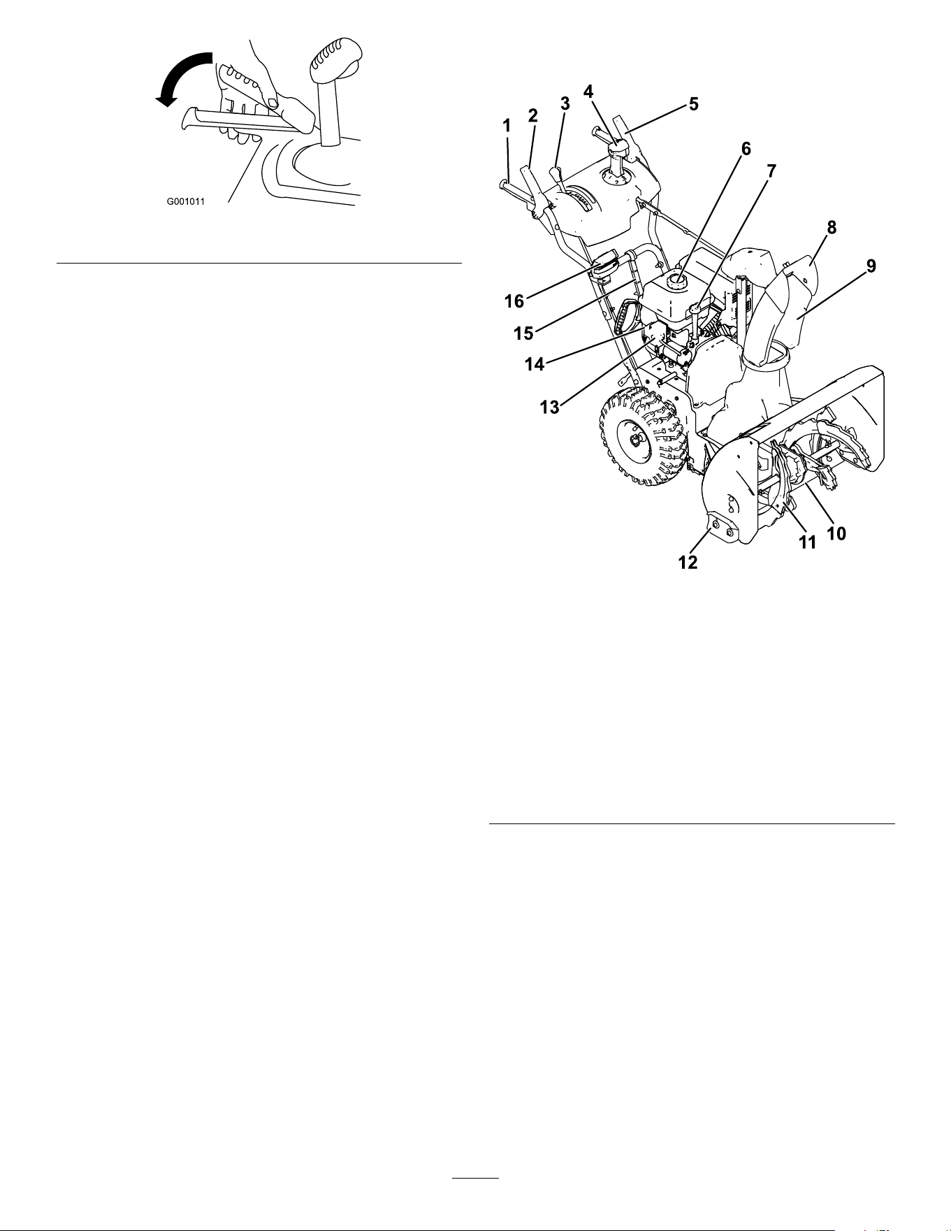
Product Overview
g254701
Figure 1 1
1. Handgrip (2)
9. Discharge chute
2. Auger/impeller lever 10. Scraper
3. Speed-selector lever
1 1. Auger
4. Quick Stick®
discharge-chute control
12. Skid (2)
5. T raction lever 13. Electric-start button
6. Fuel-tank cap 14. Electric-start plug-in
7. Oil-ll tube/dipstick 15. Snow-cleanout tool
8. Chute deector 16. Headlight (Model 37799
only)
1 1
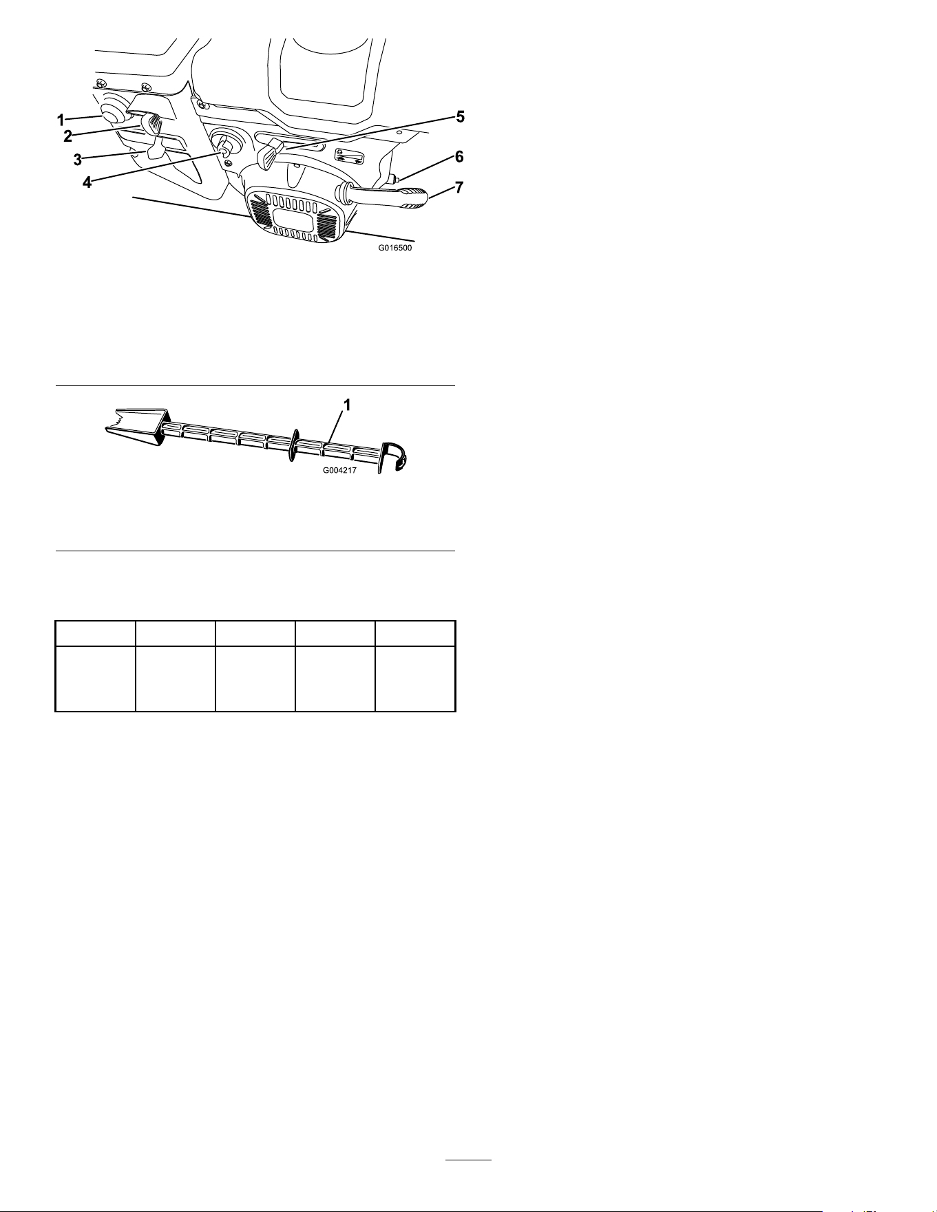
g016500
Figure 12
1. Primer 5. Throttle
2. Key
6. Oil-drain plug
3. Choke
7. Recoil-start handle
4. Fuel-shutof f valve
g004217
Figure 13
1. Snow-cleanout tool (attached to the handle)
Specications
Model W eight Length W idth Height
79 kg 142 cm 66 cm 1 17 cm
37807
(175 lb)
(56
inches)
(26
inches)
(46
inches)
Attachments/Accessories
A selection of T oro approved attachments and
accessories is available for use with the machine
to enhance and expand its capabilities. Contact
your Authorized Service Dealer or authorized T oro
distributor or go to www .T oro.com for a list of all
approved attachments and accessories.
T o ensure optimum performance and continued safety
certication of the machine, use only genuine T oro
replacement parts and accessories. Replacement
parts and accessories made by other manufacturers
could be dangerous, and such use could void the
product warranty .
Operation
Note: Determine the left and right sides of the
machine from the normal operating position.
Before Operation
Before Operation Safety
General Safety
• For electric-start models only: Use extension
cords and receptacles as specied in the manual.
Inspect the electrical cord before plugging it into
a power source. If the cord is damaged, replace
it. Unplug the power cord whenever you are not
starting the machine.
• W ear appropriate clothing, including eye
protection; long pants; substantial, slip-resistant
footwear; and hearing protection. T ie back long
hair , secure loose clothing, and do not wear loose
jewelry .
• Thoroughly inspect the area where you will use the
machine, and remove all doormats, sleds, boards,
wires, and other foreign objects.
• If a shield, safety device, or decal is damaged,
illegible, or missing, repair or replace it before
beginning operation. Also, tighten any loose
fasteners.
• Adjust the collector housing height to clear a
gravel or crushed-rock surface.
Fuel Safety
Fuel is extremely ammable and explosive. A re or
explosion from fuel can burn you and others.
• T o prevent a static charge from igniting the fuel,
place the container and/or machine on the ground
before lling, not in a vehicle or on an object.
• Fill the fuel tank outdoors when the engine is cold.
Replace the fuel cap securely and wipe up spills.
• Do not handle fuel when smoking or around an
open ame or sparks.
• Store fuel in an approved fuel container , out of the
reach of children.
• When fuel is in the tank, tip the machine only as
directed in the instructions.
• If you spill fuel on your clothing, change your
clothing immediately .
12
Filling the Fuel T ank
• For best results, use only clean, fresh (less than
30 days old), unleaded gasoline with an octane
rating of 87 or higher ((R+M)/2 rating method).
• Oxygenated fuel with up to 10% ethanol or 15%
MTBE by volume is acceptable.
• Do not use ethanol blends of gasoline (such
as E15 or E85) with more than 10% ethanol by
volume. Performance problems and/or engine
damage may result which may not be covered
under warranty .
• Do not use gasoline containing methanol.
• Do not store fuel either in the fuel tank or fuel
containers over the winter unless you use a fuel
stabilizer .
• Do not add oil to gasoline.
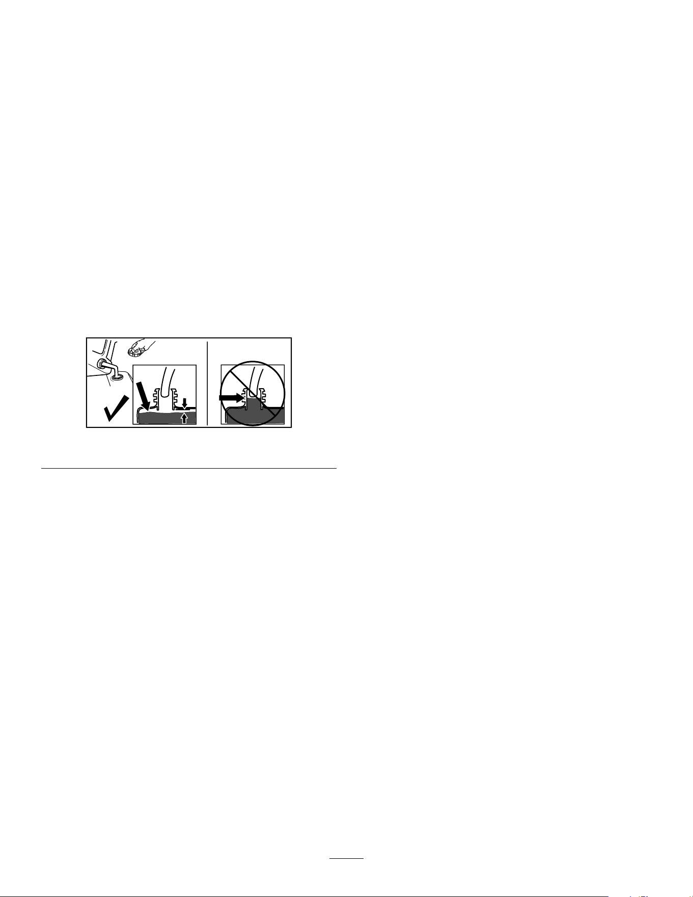
Do not ll above the bottom of the fuel tank neck
( Figure 14 ).
g216203
Figure 14
Important: For best results, purchase only the
quantity of fuel that you expect to use in 30 days.
Otherwise, you may use fuel stabilizer/conditioner
in the machine at all times to keep the fuel fresh
longer when used as directed by the fuel-stabilizer
manufacturer .
During Operation
During Operation Safety
General Safety
• Shut off the engine before unclogging the
machine and always use a stick or the
snow-cleanout tool (if provided).
• Stay behind the handles and away from the
discharge opening while operating the machine.
Keep your face, hands, feet, and any other part
of your body or clothing away from moving or
rotating parts.
• Never direct the discharge toward people or areas
where property damage can occur .
• Use your full attention while operating the
machine. Do not engage in any activity that
causes distractions; otherwise, injury or property
damage may occur .
• Exercise caution to avoid slipping or falling,
especially when operating the machine in reverse.
• Always be sure of your footing, and keep a rm
hold on the handles. W alk; never run.
• Exercise caution when operating the machine on
a slope.
• Do not operate the machine without good visibility
or light.
• Look behind and use care when backing up the
machine.
• When not actively clearing snow , disengage power
to the auger .
• Exercise caution when operating the machine on
or crossing gravel drives, walks, or roads. Stay
alert for hidden hazards or traf c.
• Never attempt to make any adjustments while
the engine is running, except as directed in the
instructions.
• After striking a foreign object, shut of f the engine,
remove the key , and inspect the machine for
damage. Repair any damage before starting the
machine.
• If the machine starts to vibrate abnormally , shut of f
the engine and check immediately for the cause.
• Do not run the engine indoors; exhaust fumes are
dangerous.
• Do not overload the machine capacity by
attempting to clear snow at too fast a rate.
• Disengage all clutches and shift into neutral before
starting the engine.
• Shut of f the engine whenever you leave the
operating position, before clearing or unclogging
the collector , impeller , or discharge chute, and
13
when making any repairs, adjustments, or
inspections.
• Never operate the machine at high transport
speeds on slippery surfaces.
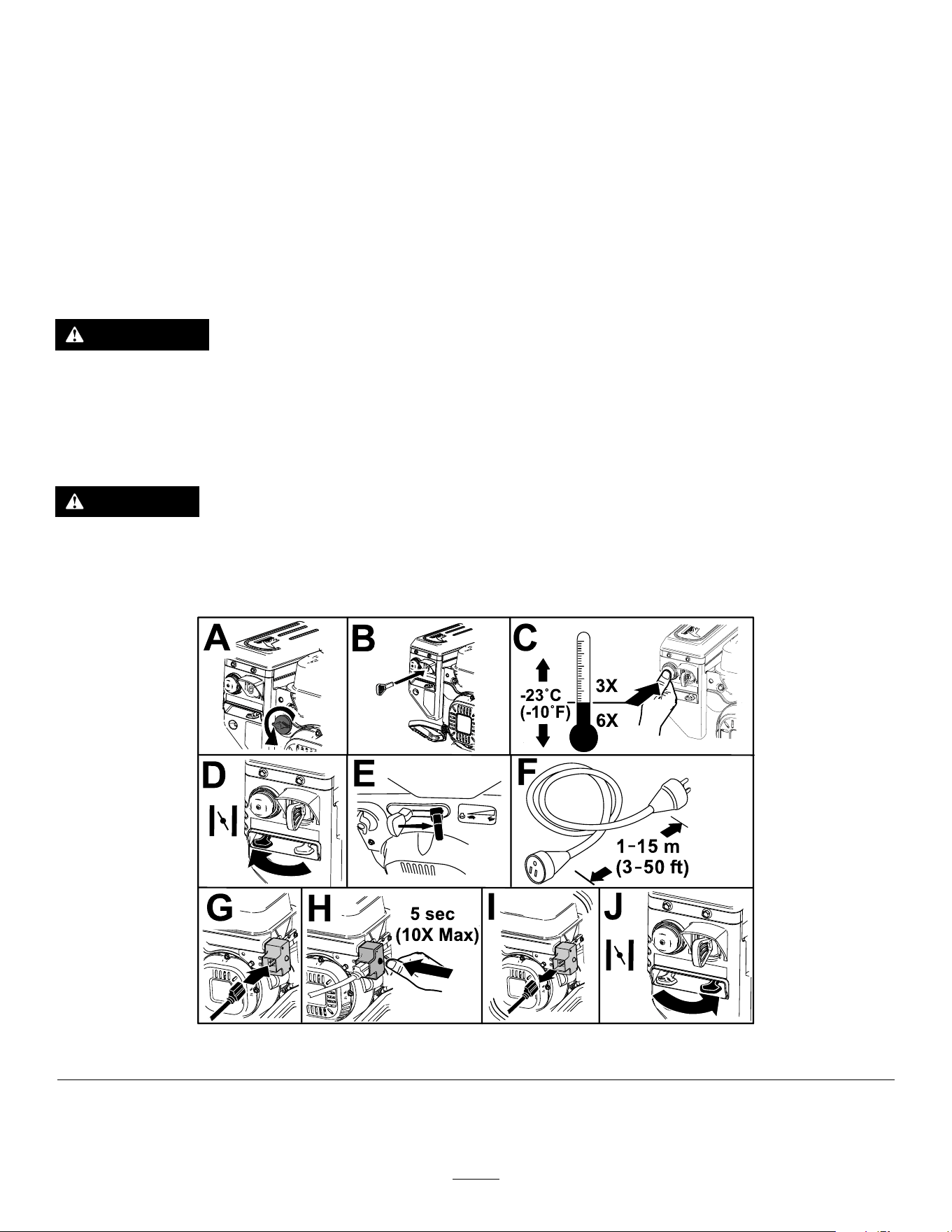
Starting the Engine
Electric-Start Model
Note: T o use the electric starter (electric-start models only), connect a power cord to the plug-in rst and then
to a power outlet. Use only a UL-listed, 16-gauge extension cord recommended for outdoor use that is not
longer than 50 ft (15 m).
W ARNING
The electrical cord can become damaged, causing a shock or re.
Thoroughly inspect the electrical cord before using the machine. If the cord is damaged, do
not use it. Replace or repair the damaged cord immediately . Contact an Authorized Service
Dealer for assistance.
CAUTION
If you leave the machine plugged into a power outlet, someone can inadvertently start the
machine and injure people or damage property .
Unplug the power cord whenever you are not starting the machine.
g254927
Figure 15
14
Standard Model
g254928
Figure 16
Shutting Off the Engine
g25241 1
Figure 17
Operating the T raction
Drive
CAUTION
If the traction drive is not properly adjusted,
the machine may move in the direction
opposite of what you intended, causing injury
and/or property damage.
Carefully check the traction drive and adjust
it properly , if necessary; refer to Checking
and Adjusting the T raction Cable ( page 20 ) for
more information.
Important: If the machine moves when the
traction lever is in the released position, check the
traction cable; refer to Checking and Adjusting
the T raction Cable ( page 20 ) or take the machine
to an Authorized Service Dealer for service.
1. T o engage the traction drive, squeeze the left
(traction) lever to the handgrip ( Figure 18 ).
g00101 1
Figure 18
2. T o stop the traction drive, release the traction
lever .
15
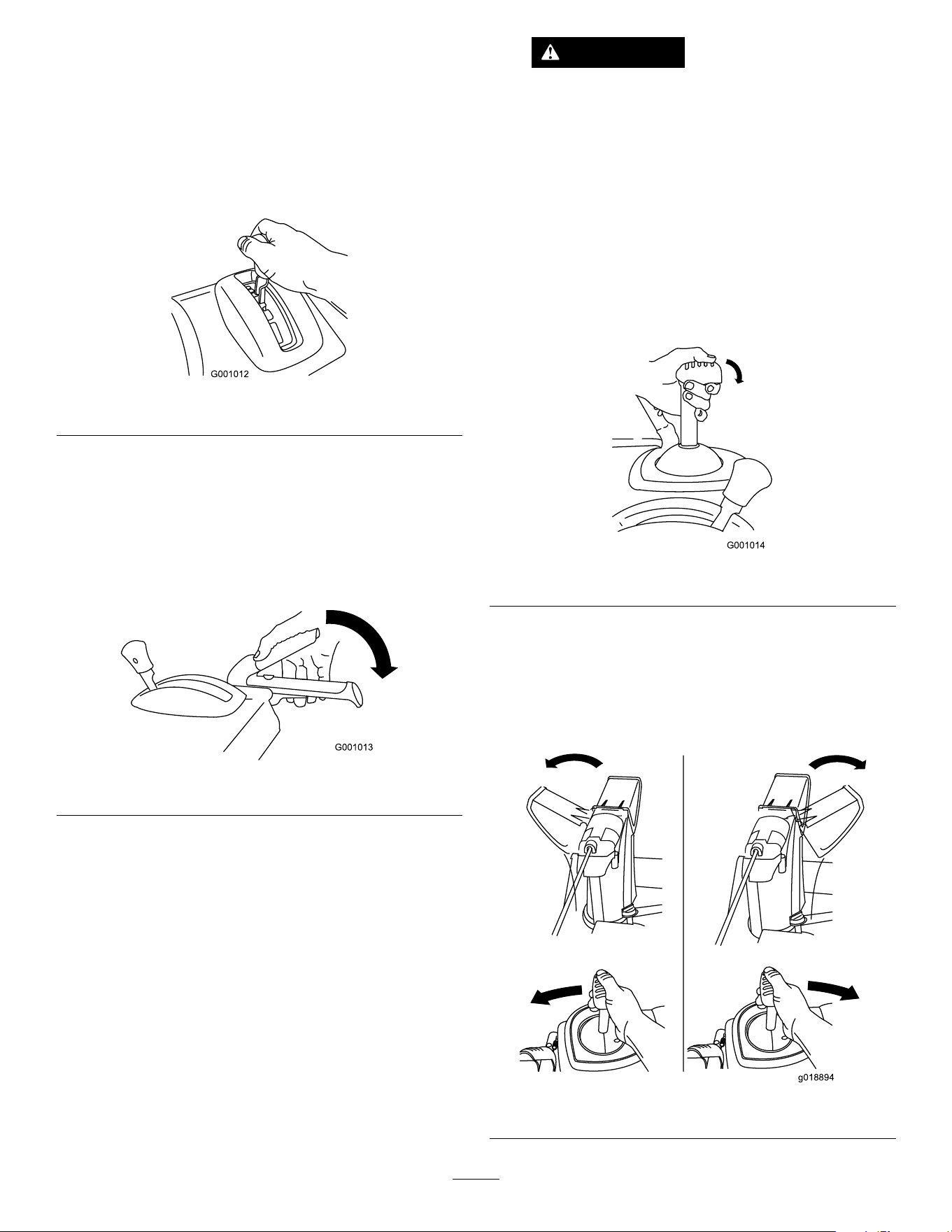
Operating the Speed
Selector
The speed selector has 6 forward and 2 reverse
gears. T o change speeds, release the traction lever
and shift the speed-selector lever to the desired
position ( Figure 19 ). The lever locks in a notch at
each speed selection.
g001012
Figure 19
Operating the
Auger/Impeller Drive
1. T o engage the auger/impeller drive, squeeze
the right (auger/impeller) lever to the handgrip
( Figure 20 ).
g001013
Figure 20
2. T o stop the auger and impeller , release the right
lever .
Important: When you engage both the
auger/impeller lever and the traction lever ,
the traction lever locks the auger/impeller
lever down, freeing your right hand. T o
release both levers, simply release the left
(traction) lever .
3. If the auger and impeller continue to rotate when
you release the auger/impeller lever , do not
operate the machine. Check the auger/impeller
cable; refer to Checking and Adjusting the
Auger/Impeller Cable ( page 21 ) and adjust it if
necessary . Otherwise, take the machine to an
Authorized Service Dealer for service.
W ARNING
If the auger and impeller continue
to rotate when you release the
auger/impeller lever , you could seriously
injure yourself or others.
Do not operate the machine. T ake it to an
Authorized Service Dealer for service.
Operating the Quick Stick
®
Hold the blue trigger cap down to use the Quick Stick
to move the discharge chute and the chute deector .
Release the trigger cap to lock the discharge chute
and chute deector into position ( Figure 21 ).
g001014
Figure 21
Moving the Discharge Chute
Hold the blue trigger cap down and move the Quick
Stick to the left to move the discharge chute to the
left; move the Quick Stick to the right to move the
discharge chute to the right ( Figure 22 ).
g018894
Figure 22
16

• If the chute does not turn as far to the left as it
does to the right, ensure that the cable is routed to
the inside of the handles. Refer to 2 Installing the
Upper Handle ( page 6 ) .
• If the chute does not move, or does not lock into
place when you release the trigger cap, you must
adjust the discharge-chute latch cable.
Moving the Chute Deector
Hold the blue trigger cap down and move the Quick
Stick forward to lower the chute deector; move it
rearward to raise the chute deector ( Figure 23 ).
g001016
Figure 23
Clearing a Clogged
Discharge Chute
W ARNING
If the auger/impeller is running but there is no
snow coming out of the discharge chute, the
discharge chute may be clogged.
Never use your hands to clear a clogged
discharge chute. This could result in personal
injury .
• T o unclog the discharge chute, stay in the
operating position and release the left (traction)
lever . While running the auger/impeller , push down
on the handles to raise the front of the machine a
few centimeters (inches) of f the pavement. Then
lift the handles quickly to bump the front of the
machine on the pavement. Repeat if necessary
until a stream of snow comes out the discharge
chute.
• If you cannot unclog the discharge chute by
bumping the front of the machine, shut off the
engine, wait for all moving parts to stop, and
use the snow-cleanout tool ( Figure 13 ).
Important: Unclogging the discharge chute
by bumping the front of the machine on the
pavement may cause the skids to move. Adjust
the skids and tighten the skid bolts securely;
refer to Checking and Adjusting the Skids and
Scraper ( page 20 ) .
17

Operating T ips
DANGER
When the machine is in operation, the impeller
and auger rotate and can injure or amputate
hands or feet.
• Before adjusting, cleaning, inspecting,
troubleshooting, or repairing the machine,
shut off the engine and wait for all moving
parts to stop. Disconnect the wire from
the spark plug and keep it away from the
plug to prevent someone from accidentally
starting the engine.
• Remove an obstruction from the discharge
chute; refer to Clearing a Clogged
Discharge Chute ( page 17 ) . Use the
snow-cleanout tool ( Figure 14 ), not your
hands, to remove an obstruction from the
discharge chute.
• Stay behind the handles and away from
the discharge opening while operating the
machine.
• Keep your face, hands, feet, and any other
part of your body or clothing away from
concealed, moving, or rotating parts.
W ARNING
The impeller can throw stones, toys, and other
foreign objects and cause serious personal
injury to you or bystanders.
• Keep the area to be cleared free of all
objects that the auger could pick up and
throw .
• Keep all children and pets away from the
area of operation.
• Always set the throttle to the F AST position when
throwing snow .
• If the engine slows down under a load or the
wheels slip, shift the machine into a lower gear .
• If the front of the machine rides up, shift the
machine into a lower gear . If the front continues to
ride up, lift up on the handles.
After Operation
After Operation Safety
General Safety
• Never store the machine with fuel in the fuel
tank inside a building where ignition sources are
present, such as hot water heaters, space heaters,
or clothes dryers. Allow the engine to cool before
storing the machine in any enclosure.
• When storing the machine for more than 30
days, refer to Storage ( page 25 ) for important
information.
• Run the machine a few minutes after throwing
snow to prevent freeze-up of the collector and
impeller .
Preventing Freeze-up after
Use
• In snowy and cold conditions, some controls and
moving parts may freeze. Do not use excessive
force when trying to operate frozen controls.
If you have dif culty operating any control or part,
start the engine and let it run for a few minutes.
• After using the machine, let the engine run for
a few minutes to prevent moving parts from
freezing. Engage the auger/impeller to clear any
remaining snow from inside the housing. Rotate
the Quick Stick to prevent it from freezing. Shut of f
the engine, wait for all moving parts to stop, and
remove all ice and snow from the machine.
• With the engine of f, pull the recoil-start handle
several times and push the electric-start button
once to prevent the recoil starter and electric
starter from freezing up.
18

Maintenance
Recommended Maintenance Schedule(s)
Maintenance Service
Interval
Maintenance Procedure
After the rst 2 hours
• Inspect the traction cable and adjust it if necessary .
• Inspect the auger/impeller cable and adjust it if necessary .
After the rst 5 hours
• Change the engine oil.
Before each use or daily
• Check the engine-oil level and add oil if necessary .
Every 100 hours
• Replace the spark plug.
Y early
• Check the skids and the scraper and adjust them if necessary .
• Inspect the traction cable and adjust or replace it if necessary .
• Inspect the auger/impeller cable and adjust or replace it if necessary .
• Check the auger-gearbox oil and add oil if necessary .
• Change the engine oil.
• Lubricate the hex shaft.
Y early or before storage
• Check the air pressure in the tires and inate them to 1 16 to 137 kPa (17 to 20 psi).
• Drain the fuel and run the engine to dry out the fuel tank and the carburetor at the
end of the season.
• Have an Authorized Service Dealer inspect and replace the traction drive belt and/or
the auger/impeller drive belt, if necessary .
Maintenance Safety
Read the following safety precautions before
performing any maintenance on the machine:
• Shut of f the engine, remove the key , and wait
for all movement to stop before you leave the
operator ’ s position. Allow the machine to cool
before adjusting, servicing, cleaning, or storing it.
• Always wear eye protection while performing an
adjustment or repair to protect your eyes from
foreign objects that the machine may throw .
• Check all fasteners at frequent intervals for proper
tightness to ensure that the machine is in safe
working condition.
• Do not change the governor settings on the engine.
Purchase only genuine T oro replacement parts
and accessories.
Preparing for Maintenance
1. Move the machine to a level surface.
2. Shut of f the engine and wait for all moving parts
to stop.
3. Disconnect the spark-plug wire. Refer to
Replacing the Spark Plug ( page 24 ) .
19
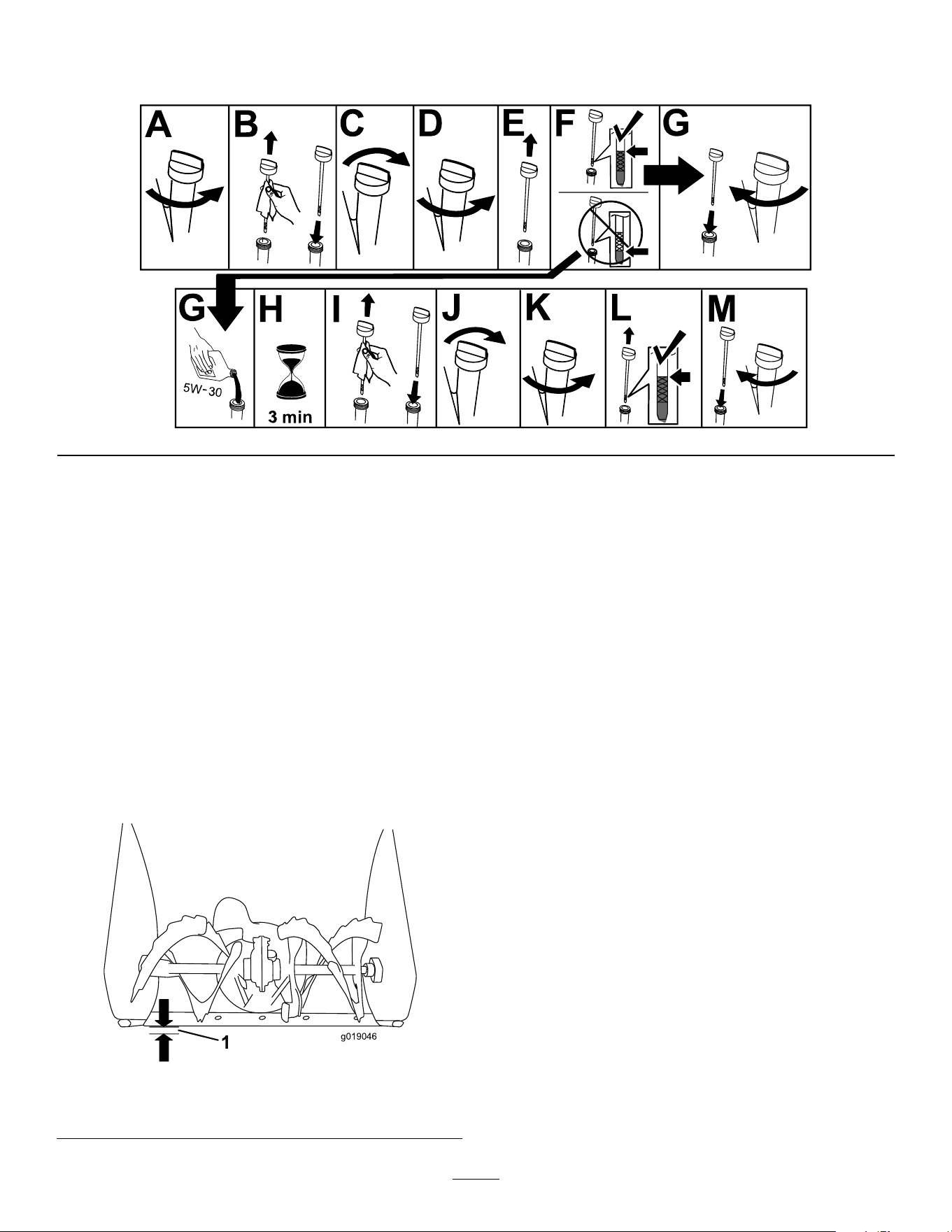
Checking the Engine-Oil Level
Service Interval : Before each use or daily —Check the engine-oil level and add oil if necessary .
g257528
Checking and Adjusting the
Skids and Scraper
Service Interval : Y early —Check the skids and
the scraper and adjust them if
necessary .
Check the skids and the scraper to ensure that the
auger does not contact the paved or gravel surface.
Adjust the skids and the scraper as needed to
compensate for wear .
1. Check the tire pressure; refer to 7 Checking the
T ire Pressure ( page 9 ) .
2. Loosen the nuts that secure both skids to the
auger sides until the skids slide up and down
easily .
g019046
Figure 25
1. 3 mm (1/8 inch)
Important: The auger blades must be
supported above the ground by the skids.
3. Ensure that the scraper is 3 mm (1/8 inch) above
and parallel to a level surface.
Note: If the pavement is cracked, rough, or
uneven, adjust the skids to raise the scraper . For
gravel surfaces, adjust the skids further down to
prevent the machine from picking up rocks.
4. Move the skids down until they are even with
the ground.
5. Firmly tighten the nuts that secure both skids
to the auger sides.
Note: T o quickly adjust the skids if they loosen,
support the scraper 3 mm (1/8 inch) of f the
pavement, then adjust the skids down to the
pavement.
Note: If the skids become excessively worn,
you can turn them over and set the unused side
toward the pavement.
Checking and Adjusting the
T raction Cable
Service Interval : After the rst 2 hours —Inspect
the traction cable and adjust it if
necessary .
Y early —Inspect the traction cable and adjust or
replace it if necessary .
20
If the machine does not drive in the forward or reverse
speeds or it drives when you release the traction lever ,
adjust the traction cable.
If the left (traction) cable is not properly adjusted, do
the following steps:
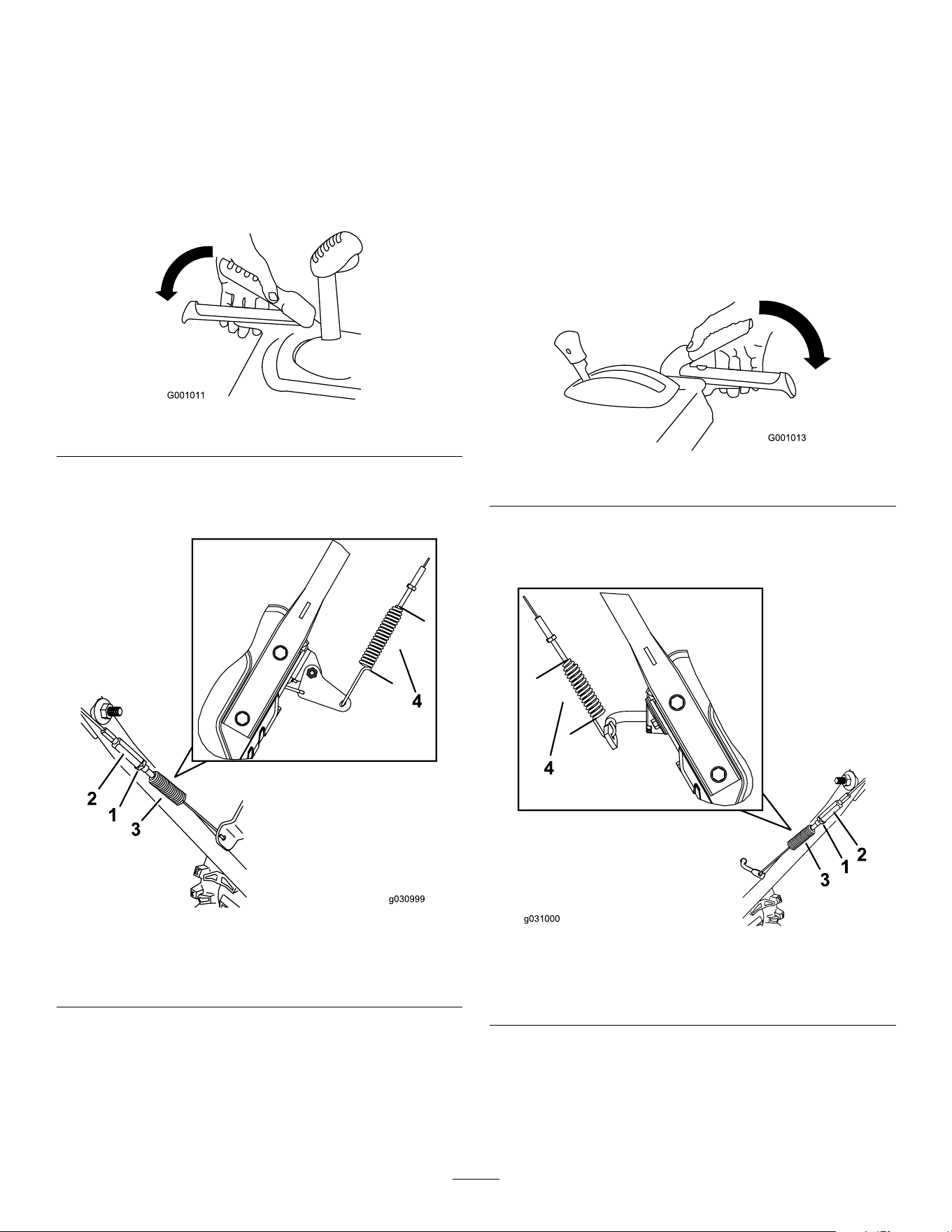
1. Loosen the jam nut.
2. Engage the traction lever and hold it in place
( Figure 26 ).
g00101 1
Figure 26
3. Loosen or tighten the turnbuckle to adjust the
spring length to 5.5 cm (2–3/16 inches) as
shown in Figure 27 .
g030998
Figure 27
1. Jam nut
3. Spring
2. T urnbuckle
4. 5.5 cm (2–3/16 inches)
4. T ighten the jam nut ( Figure 27 ), ensuring that
there is slight tension on the cable.
5. If the traction cable is properly adjusted but a
problem remains, contact an Authorized Service
Dealer .
Checking and Adjusting the
Auger/Impeller Cable
Service Interval : After the rst 2 hours —Inspect the
auger/impeller cable and adjust it if
necessary .
Y early —Inspect the auger/impeller cable and
adjust or replace it if necessary .
1. Loosen the jam nut.
2. Engage the auger/impeller lever and hold it in
place ( Figure 28 ).
g001013
Figure 28
3. Loosen or tighten the turnbuckle to adjust the
spring length to 7 cm (2-3/4 inches) as shown
in Figure 29 .
g031000
Figure 29
1. Jam nut
3. Spring
2. T urnbuckle
4. 7 cm (2-3/4 inches)
4. T ighten the jam nut ( Figure 29 ), ensuring that
there is slight tension on the cable.
5. If the auger/impeller cable is properly adjusted
but a problem remains, contact an Authorized
Service Dealer .
21
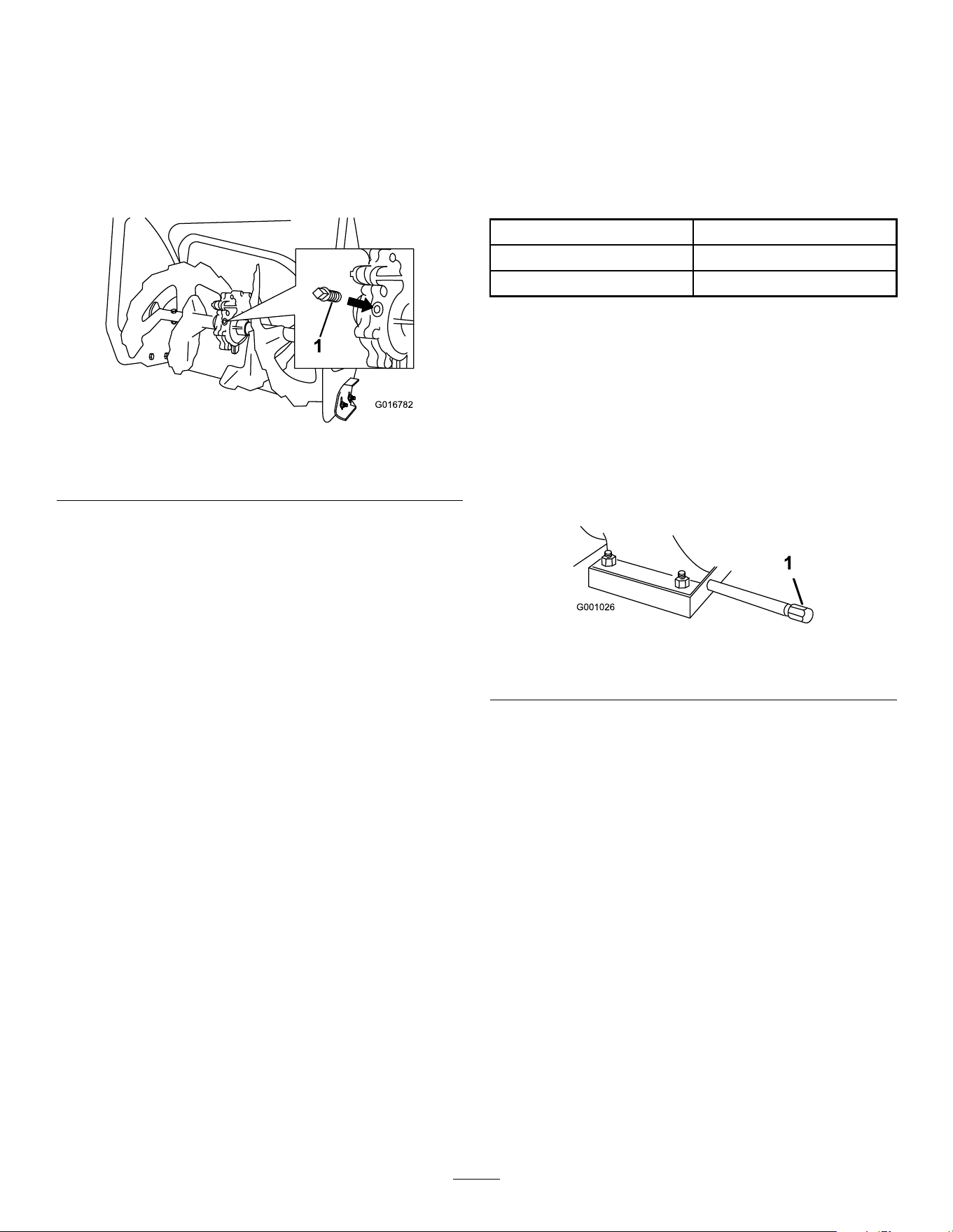
Checking the
Auger-Gearbox-Oil Level
Service Interval : Y early —Check the auger-gearbox
oil and add oil if necessary .
1. Move the machine to a level surface.
2. Clean the area around the pipe plug ( Figure 30 ).
g016782
Figure 30
1. Pipe plug
3. Remove the pipe plug from the gearbox.
4. Check the oil level in the gearbox. The oil should
be 9.5 mm (3/8 inch) below the ller opening.
5. If the oil level is low , add GL-5 or GL-6, SAE
80-90 EP gear oil lubricant to the gearbox until
the oil level is 9.5 mm (3/8 inch) below the ller
opening.
Note: Do not use synthetic oil.
6. Install the pipe plug in the gearbox.
Changing the Engine Oil
Service Interval : After the rst 5 hours —Change the
engine oil.
Y early —Change the engine oil.
If possible, run the engine for a few minutes before
changing the oil because warm oil ows better and
carries more contaminants.
Engine oil capacity
0.70 L (24 oz)*
Oil viscosity Refer to Figure 32 .
API service classication SJ or higher
*There is residual oil in the crankcase after you drain
the oil. Do not pour the entire capacity of oil into the
crankcase. Fill the crankcase with oil as directed in
the following steps.
Use Figure 32 below to select the best oil viscosity for
the outdoor temperature range expected:
1. Move the machine to a level surface.
2. Clean the area around the oil-drain cap ( Figure
31 ).
g001026
Figure 31
1. Oil-drain cap
3. Slide an oil-drain pan under the drain extension
and remove the oil-drain cap.
4. Drain the oil.
Note: Dispose of the used oil properly at a local
recycling center .
5. Install the oil-drain cap and tighten it securely .
6. Clean around the oil ll/dipstick.
7. Unscrew the dipstick and remove it.
8. Carefully pour about 3/4 of the engine capacity
of oil into the oil-ll tube.
Use Figure 32 to select the best oil viscosity for
the outdoor temperature range expected:
22
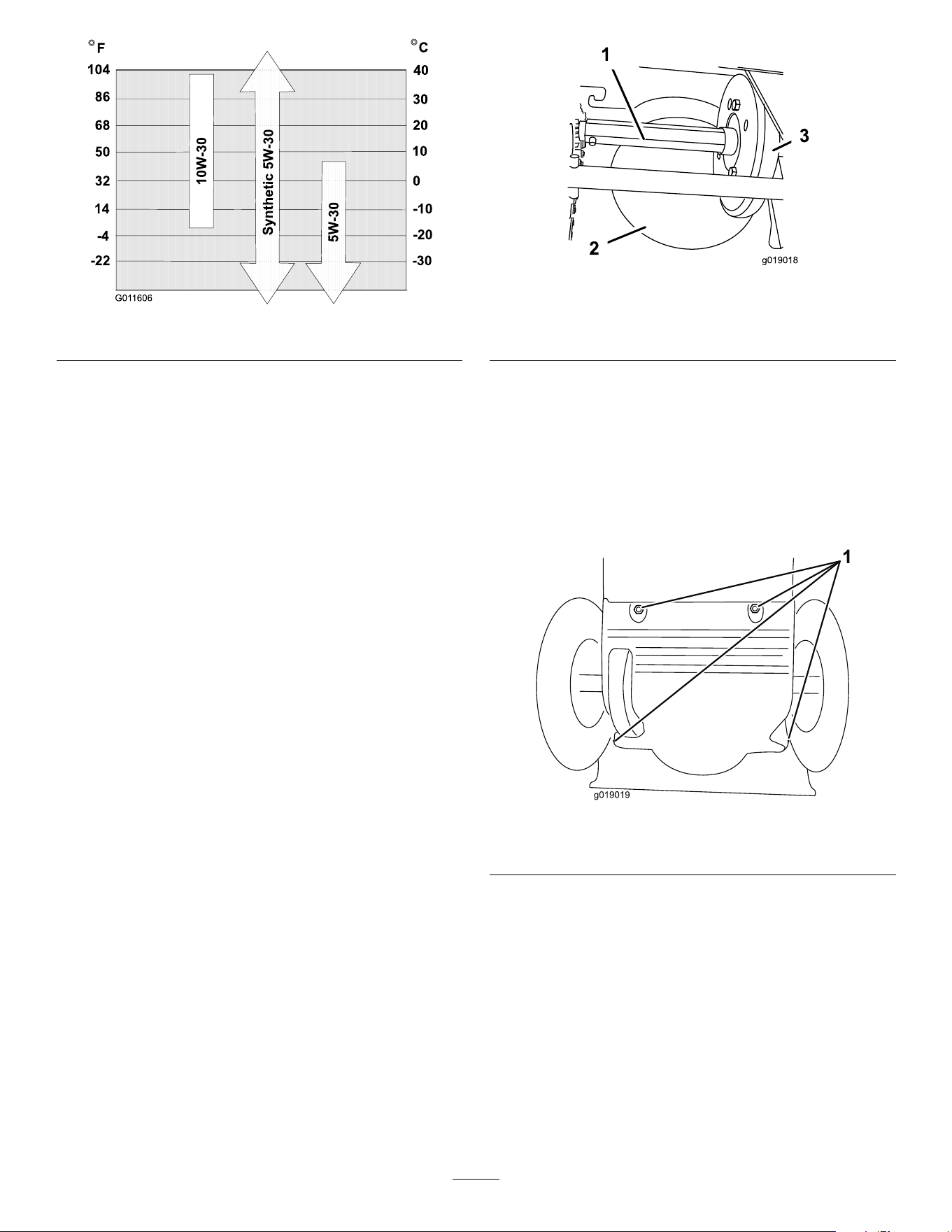
g01 1606
Figure 32
9. W ait 3 minutes for the oil to settle in the engine.
10. Wipe the dipstick clean with a clean cloth.
1 1. Insert the dipstick into the oil-ll tube, but do not
screw it in , then remove the dipstick.
12. Read the oil level on the dipstick.
• If the oil level on the dipstick is too low ,
carefully pour a small amount of oil into
the oil-ll tube, wait 3 minutes, and repeat
steps 10 through 12 until the oil level on the
dipstick is correct.
• If the oil level on the dipstick is too high,
drain the excess oil until the oil level on the
dipstick is correct.
Important: If the oil level in the engine is too
low or too high and you run the engine, you
may damage the engine.
13. Install the dipstick into the oil-ll tube securely .
Lubricating the Hex Shaft
Service Interval : Y early —Lubricate the hex shaft.
Lightly lubricate the hex shaft yearly with automotive
engine oil ( Figure 33 ).
g019018
Figure 33
1. Hex shaft
3. Rubber wheel
2. Steel friction pulley
Important: Do not get oil on the rubber wheel or
the steel friction pulley because the traction drive
will slip ( Figure 33 ).
1. Drain the fuel from the fuel tank.
2. T ip the machine forward onto its auger housing
and block it so that it cannot fall.
3. Remove the back cover ( Figure 34 ).
g019019
Figure 34
1. Screws
4. Move the speed-selector lever to Position R2.
5. Dip your nger in automotive engine oil and
lightly lubricate the hex shaft.
6. Move the speed-selector lever to Position 6.
7. Lubricate the other end of the hex shaft.
8. Move the speed-selector lever forward and
rearward a few times.
9. Install the back cover and return the machine to
the operating position.
23
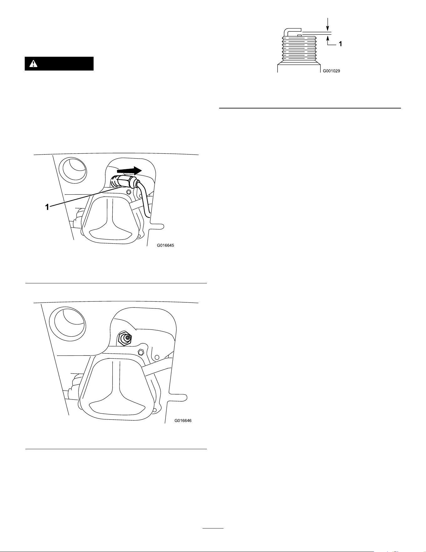
Replacing the Spark Plug
Service Interval : Every 100 hours —Replace the
spark plug.
W ARNING
Replacing the spark plug while the engine is
hot can result in burns.
W ait until the engine is cool to replace the
spark plug.
Use a T oro spark plug or equivalent (Champion®
RN9YC or NGK BPR6ES).
1. Remove the boot ( Figure 35 ).
g016645
Figure 35
1. Spark-plug boot
2. Clean around the base of the spark plug.
g016646
Figure 36
3. Remove and discard the old spark plug.
Note: Y ou will need a ratchet wrench extension
to remove the spark plug.
4. Set the gap between the electrodes on a new
spark plug at 0.76 mm (0.030 inch) as shown
in Figure 37 .
g001029
Figure 37
1. 0.76 mm (0.030 inch)
5. Install the new spark plug, tighten it rmly , and
attach the ignition wire to the spark plug.
Note: Ensure that the ignition wire snaps
completely into place on the spark plug.
Replacing the Drive Belts
If the auger/impeller drive belt or the traction-drive belt
becomes worn, oil-soaked, or otherwise damaged,
have an Authorized Service Dealer replace the belt.
24
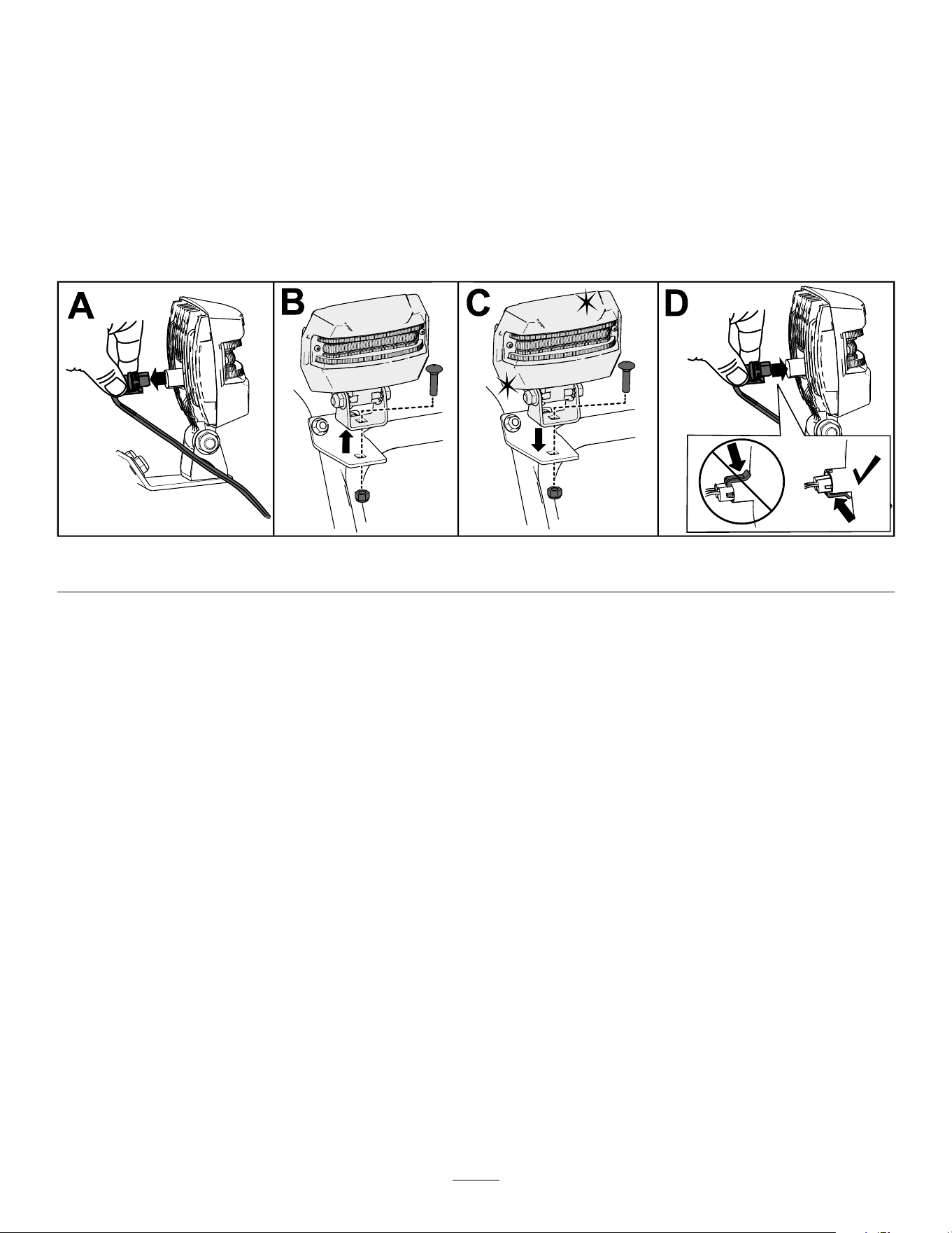
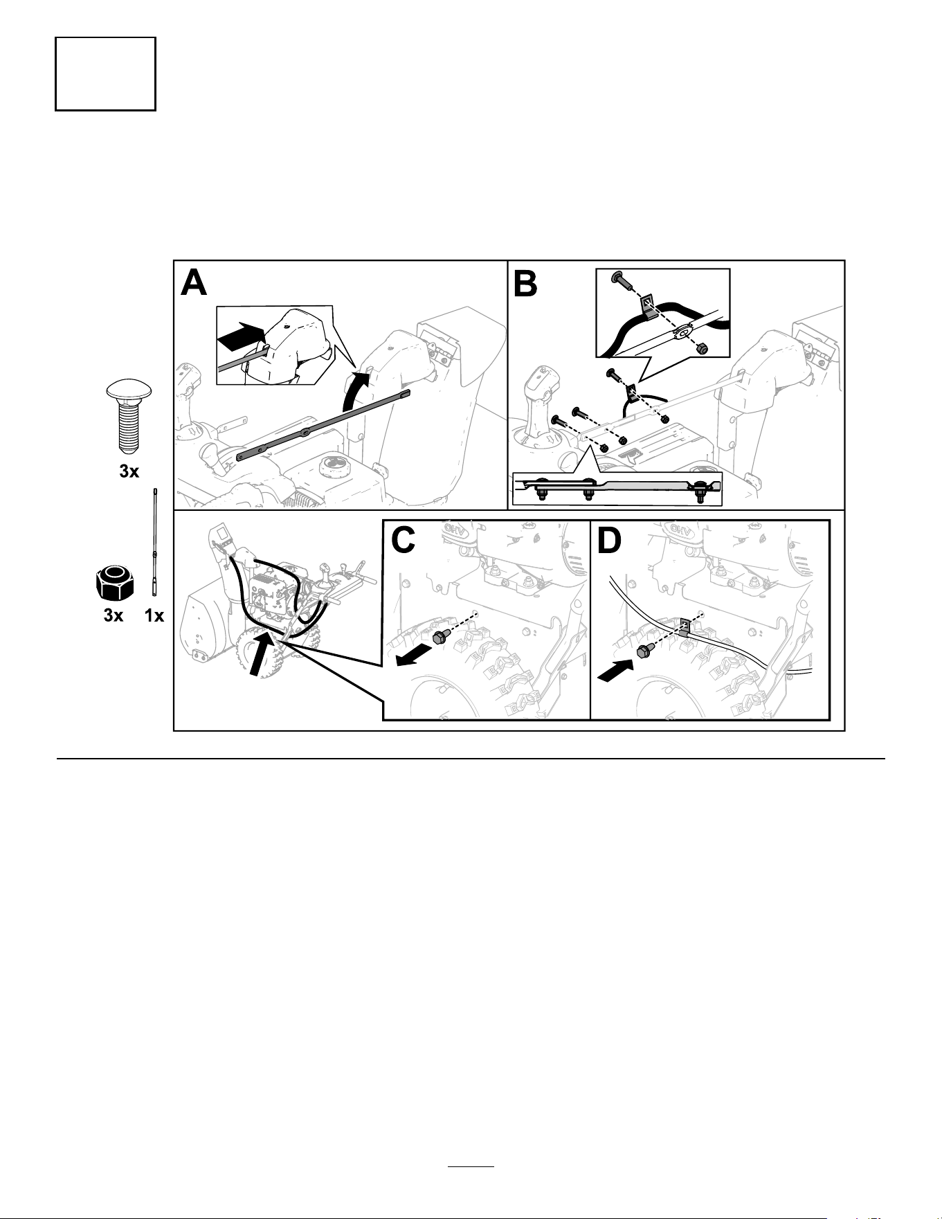
Replacing the Headlight
Model 37799 only
Replace the headlight assembly (T oro part number 138-0670) when needed.
1. Remove the headlight wire from the back of the headlight (A of Figure 38 ).
2. Remove the bolt and nut holding the headlight assembly onto the headlight bracket and then remove the
old headlight assembly (B of Figure 38 ).
3. Secure the new headlight assembly onto the headlight bracket with the previously removed nut and
bolt (C of Figure 38 ).
4. Insert the headlight wire straight into the back of the headlight until it is securely in place (D of Figure 38 ).
g256137
Figure 38
Storage
Storage Safety
• Shut of f the engine, remove the key , and wait
for all movement to stop before you leave the
operator ’ s position. Allow the machine to cool
before adjusting, servicing, cleaning, or storing it.
• Fuel fumes are highly ammable, explosive, and
dangerous if inhaled. If you store the product in an
area with an open ame, the fuel fumes may ignite
and cause an explosion.
• Do not store the machine in a house (living
area), basement, or any other area where ignition
sources may be present, such as hot water and
space heaters, clothes dryers, furnaces, and other
appliances.
• Do not tip the machine either forward or backward
with fuel in the fuel tank; otherwise, fuel may leak
out of the machine.
• Do not store the machine with its handle tipped
down onto the ground; otherwise, oil may leak into
the engine cylinder and onto the ground, and the
engine may not start.
Storing the Machine
1. On the last refueling of the year , add fuel
stabilizer to fresh fuel as directed by the fuel
stabilizer manufacturer .
Important: Do not store fuel longer
than that suggested by the fuel stabilizer
manufacturer .
2. Run the engine for 10 minutes to distribute the
conditioned fuel through the fuel system.
3. Run the machine until the engine runs out of fuel.
4. Prime the engine and start it again.
5. Allow the engine to run until it shuts of f.
When you can no longer start the engine, it is
suf ciently dry .
6. Allow the engine to cool.
7. Remove the key .
8. Clean the machine thoroughly .
9. T ouch up chipped surfaces with paint available
from an Authorized Service Dealer . Sand
af fected areas before painting, and use a rust
preventative to prevent the metal parts from
rusting.
25

10. T ighten all loose screws, bolts, and locknuts.
Repair or replace any damaged parts.
1 1. Cover the machine and store it in a clean, dry
place out of the reach of children.
Removing the Machine
from Storage
Perform the annual maintenance procedures as given
in the Recommended Maintenance Schedule; refer to
Maintenance ( page 19 ) .
26

T roubleshooting
Problem
Possible Cause Corrective Action
1. The power cord is disconnected at the
outlet or the machine.
1. Connect the power cord to the outlet
and/or the machine.
2. The power cord is worn, corroded, or
damaged.
2. Replace the power cord.
The electric starter does not turn
(electric-start models only).
3. The power outlet is not energized.
3. Have a qualied electrician energize
the outlet.
1. The key is not in the ignition. 1. Insert the key into the ignition.
2. The choke is in the O FF position and
the primer has not been pressed.
2. Move the choke to the O N position and
press the primer 3 times.
3. The fuel-shutof f valve is not open. 3. Open the fuel-shutof f valve.
4. The throttle is not in the F AST position. 4. Move the throttle to the F AST position.
5. The fuel tank is empty or the fuel
system contains stale fuel.
5. Drain and/or ll the fuel tank with
fresh fuel (not more than 30 days old).
If the problem persists, contact an
Authorized Service Dealer .
6. The spark-plug wire is loose or
disconnected.
6. Connect the wire to the spark plug.
7. The spark plug is pitted, fouled, or the
gap is incorrect.
7. Check the spark plug and adjust the
gap if necessary . Replace the spark
plug if it is pitted, fouled, or cracked.
8. The fuel-vent cap is restricted.
8. Remove the vent restriction or replace
the fuel cap.
The engine does not start or starts hard.
9. The engine-oil level in the engine
crankcase is too low or too high.
9. Add or drain oil to adjust the oil level in
the engine crankcase to the Full mark
on the dipstick.
1. The choke is in the O N position. 1. Move the choke to the O FF position.
2. The fuel-shutof f valve is not completely
open.
2. Open the fuel-shutof f valve.
3. The fuel tank is nearly empty or
contains stale fuel.
3. Drain and ll the fuel tank with fresh
fuel (not more than 30 days old).
If the problem persists, contact an
Authorized Service Dealer .
4. The spark-plug wire is loose.
4. Connect the wire to the spark plug.
5. The spark plug is pitted, fouled, or the
gap is incorrect.
5. Check the spark plug and adjust the
gap if necessary . Replace the spark
plug if it is pitted, fouled, or cracked.
The engine runs rough.
6. The engine-oil level in the engine
crankcase is too low or too high.
6. Add or drain oil to adjust the oil level in
the engine crankcase to the Full mark
on the dipstick.
27

Problem
Possible Cause Corrective Action
1. The throttle is not in the F AST position
when throwing snow .
1. Move the throttle to the F AST position.
2. The machine is moving too fast to clear
the snow .
2. Shift the machine into a lower gear .
3. Y ou are trying to remove too much
snow per swath.
3. Reduce the amount of snow removed
per swath.
4. Y ou are trying to remove extremely
heavy or wet snow .
4. Do not overload the machine with
extremely heavy or wet snow .
5. The discharge chute is plugged. 5. Unclog the discharge chute.
6. The auger/impeller drive belt is loose
or is of f the pulley .
6. Install and/or adjust the auger/impeller
drive belt; refer to www .T oro.com
for servicing information or take the
machine to an Authorized Service
Dealer .
The engine runs, but the machine
discharges snow poorly or not at all.
7. The auger/impeller drive belt is worn
or broken.
7. Replace the auger/impeller drive belt;
refer to www .T oro.com for servicing
information or take the machine to an
Authorized Service Dealer .
The discharge chute either does not lock
into place or does not move.
1. The discharge-chute latch cable is not
properly adjusted.
1. Adjust the discharge-chute latch cable.
1. The skids and/or scraper are not
properly adjusted.
1. Adjust the skids and/or the scraper .
The machine does not properly clear the
snow of f the surface.
2. The pressure in the tires is not equal.
2. Check and adjust the pressure in 1 or
both tires.
28

Notes:

Notes:

California Proposition 65 W arning Information
What is this warning?
Y ou may see a product for sale that has a warning label like the following:
W ARNING: Cancer and Reproductive Harm—www .p65W arnings.ca.gov .
What is Prop 65?
Prop 65 applies to any company operating in California, selling products in California, or manufacturing products that may be sold in or brought into
California. It mandates that the Governor of California maintain and publish a list of chemicals known to cause cancer , birth defects, and/or other
reproductive harm. The list, which is updated annually , includes hundreds of chemicals found in many everyday items. The purpose of Prop 65 is to
inform the public about exposure to these chemicals.
Prop 65 does not ban the sale of products containing these chemicals but instead requires warnings on any product, product packaging, or literature with
the product. Moreover , a Prop 65 warning does not mean that a product is in violation of any product safety standards or requirements. In fact, the
California government has claried that a Prop 65 warning “is not the same as a regulatory decision that a product is ‘safe’ or ‘unsafe.’” Many of these
chemicals have been used in everyday products for years without documented harm. For more information, go to https://oag.ca.gov/prop65/faqs-view-all .
A Prop 65 warning means that a company has either (1) evaluated the exposure and has concluded that it exceeds the “no signicant risk level”; or (2)
has chosen to provide a warning based on its understanding about the presence of a listed chemical without attempting to evaluate the exposure.
Does this law apply everywhere?
Prop 65 warnings are required under California law only . These warnings are seen throughout California in a wide range of settings, including but not
limited to restaurants, grocery stores, hotels, schools, and hospitals, and on a wide variety of products. Additionally , some online and mail order
retailers provide Prop 65 warnings on their websites or in catalogs.
How do the California warnings compare to federal limits?
Prop 65 standards are often more stringent than federal and international standards. There are various substances that require a Prop 65 warning
at levels that are far lower than federal action limits. For example, the Prop 65 standard for warnings for lead is 0.5 μg/day , which is well below
the federal and international standards.
Why don’t all similar products carry the warning?
• Products sold in California require Prop 65 labelling while similar products sold elsewhere do not.
• A company involved in a Prop 65 lawsuit reaching a settlement may be required to use Prop 65 warnings for its products, but other companies
making similar products may have no such requirement.
• The enforcement of Prop 65 is inconsistent.
• Companies may elect not to provide warnings because they conclude that they are not required to do so under Prop 65; a lack of warnings for a
product does not mean that the product is free of listed chemicals at similar levels.
Why does T oro include this warning?
T oro has chosen to provide consumers with as much information as possible so that they can make informed decisions about the products they buy and
use. T oro provides warnings in certain cases based on its knowledge of the presence of one or more listed chemicals without evaluating the level of
exposure, as not all the listed chemicals provide exposure limit requirements. While the exposure from T oro products may be negligible or well within the
“no signicant risk” range, out of an abundance of caution, T oro has elected to provide the Prop 65 warnings. Moreover , if T oro does not provide these
warnings, it could be sued by the State of California or by private parties seeking to enforce Prop 65 and subject to substantial penalties.
Rev A