
Form No. 3432-529 Rev C
SnowMaster
®
724 QXE and 824 QXE Snowthrower
Model No. 36002—Serial No. 405346200 and Up
Model No. 36003—Serial No. 405346200 and Up
Operator's Manual
Introduction
This machine is intended to be used by residential
homeowners. It is designed primarily for removing
snow from paved surfaces, such as driveways and
sidewalks, and other surfaces for trafc on residential
or commercial properties. It is not designed for
removing materials other than snow, nor is it designed
for clearing gravel surfaces. Using this product for
purposes other than its intended use could prove
dangerous to you and bystanders.
Read this information carefully to learn how to operate
and maintain your product properly and to avoid
injury and product damage. You are responsible for
operating the product properly and safely.
Visit
www.Toro.com for product safety and operation
training materials, accessory information, help nding
a dealer, or to register your product.
Whenever you need service, genuine Toro parts, or
additional information, contact an Authorized Service
Dealer or Toro Customer Service and have the model
and serial numbers of your product ready. Figure 1
identies the location of the model and serial numbers
on the product. Write the numbers in the space
provided.
Important: With your mobile device, you can
scan the QR code on the serial number decal (if
equipped) to access warranty, parts, and other
product information.
g292964
Figure 1
1. Model and serial number location
Model No.
Serial No.
This manual identies potential hazards and has
safety messages identied by the safety-alert symbol
(Figure 2), which signals a hazard that may cause
serious injury or death if you do not follow the
recommended precautions.
g000502
Figure 2
Safety-alert symbol
This manual uses 2 words to highlight information.
Important calls attention to special mechanical
information and Note emphasizes general information
worthy of special attention.
Important: If you are using this machine above
1500 m (5,000 ft) for a continuous period, ensure
that the High Altitude Kit has been installed
so that the engine meets CARB/EPA emission
regulations. The High Altitude Kit increases
engine performance while preventing spark-plug
fouling, hard starting, and increased emissions.
Once you have installed the kit, attach the
high-altitude label next to the serial decal on the
machine. Contact any Authorized Toro Service
Dealer to obtain the proper High Altitude Kit and
high-altitude label for your machine. To locate
a dealer convenient to you, access our website
at
www.Toro.com or contact our Toro Customer
Care Department at the number(s) listed in your
Emission Control Warranty Statement. Remove
the kit from the engine and restore the engine to
its original factory conguration when running the
engine under 1500 m (5,000 ft). Do not operate an
engine that has been converted for high-altitude
use at lower altitudes; otherwise, you could
overheat and damage the engine.
If you are unsure whether or not your machine has
been converted for high-altitude use, look for the
following label (
Figure 3).
© 2020—The Toro® Company
8111 Lyndale Avenue South
Bloomington, MN 55420 Register at www.Toro.com.
Original Instructions (EN)
Printed in Mexico
All Rights Reserved
*3432-529*

decal127-9363
Figure 3
WARNING
CALIFORNIA
Proposition 65 Warning
The engine exhaust from this product
contains chemicals known to the State of
California to cause cancer, birth defects,
or other reproductive harm.
Use of this product may cause exposure
to chemicals known to the State of
California to cause cancer, birth defects,
or other reproductive harm.
Contents
Introduction ............................................................... 1
Safety ....................................................................... 3
General Safety ................................................... 3
Safety and Instructional Decals .......................... 4
Setup ........................................................................ 5
1 Unfolding the Handle ....................................... 5
2 Installing the Discharge Chute ......................... 5
3 Installing the Chute-Control Rod ...................... 5
4 Checking the Engine-Oil Level ......................... 6
5 Adjusting the Tire Pressure .............................. 6
Product Overview ..................................................... 8
Specications .................................................... 8
Attachments/Accessories................................... 8
Operation .................................................................. 8
Before Operation ................................................... 8
Before Operation Safety ..................................... 8
Filling the Fuel Tank............................................ 9
Checking the Engine-Oil Level.......................... 10
During Operation ................................................. 10
During Operation Safety ................................... 10
Starting the Engine ............................................11
Engaging the Auger...........................................11
Disengaging the Auger ......................................11
Self-Propelling the Machine.............................. 12
Shutting Off the Engine..................................... 12
Operating the Quick Stick®............................... 12
Clearing a Clogged Discharge Chute ................ 12
Operating Tips ................................................. 13
After Operation .................................................... 13
After Operation Safety ...................................... 13
Preventing Freeze-up after Use ........................ 13
Maintenance ........................................................... 14
Recommended Maintenance Schedule(s) ........... 14
Maintenance Safety.......................................... 14
Checking and Adjusting the Skids..................... 14
Inspecting the Throwing Edges......................... 15
Changing the Engine Oil ................................... 16
Replacing the Spark Plug ................................. 17
Adjusting the Auger Cable ................................ 17
Adjusting the Transmission Cable..................... 18
Storage ................................................................... 19
Storage Safety.................................................. 19
Storing the Machine.......................................... 19
2

Safety
This machine has been designed in accordance with
ANSI/OPEI B71.3 specications.
General Safety
This product is capable of amputating hands and
feet and of throwing objects. Always follow all safety
instructions to avoid serious personal injury.
• Read and understand the contents of this
Operator’s Manual before you start the engine.
Ensure that everyone using this product knows
how to use it, knows how to shut off the engine
quickly, and understands the warnings.
• Shut off the engine whenever you leave the
operating position for any reason.
• Do not put your hands or feet near moving parts
on the machine.
• Do not operate the machine without all guards
and other safety protective devices in place and
working.
• Keep clear of any discharge opening. Keep
bystanders, especially small children, out of the
operating area.
• Never allow children to operate the machine.
3
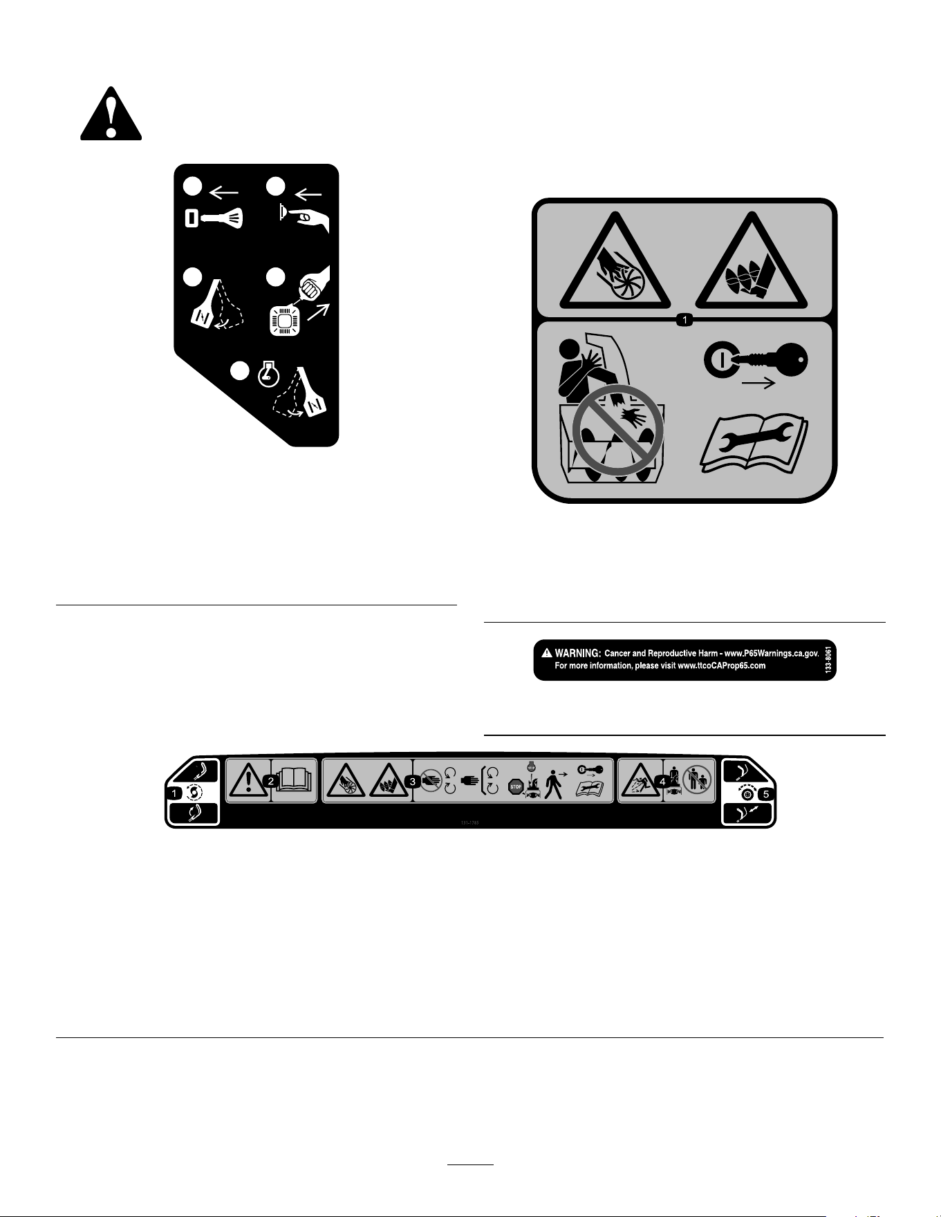
Safety and Instructional Decals
Safety decals and instructions are easily visible to the operator and are located near any area
of potential danger. Replace any decal that is damaged or missing.
x 3
1
2
3
4
5
120-9805
decal120-9805
120-9805
1. Insert the key.
2. Prime the engine 3 times.
3. Engage the choke.
4. Pull the starter cord.
5. Once the engine is running, disengage the choke.
Order part no 131-5915
decal131-5914
131-5914
1. Cutting/dismemberment hazard of hand or foot, impeller
and auger—do not place your hand in the chute; remove
the key and read the Operator’s Manual before performing
maintenance.
decal133-8061
133-8061
decal131-1785
131-1785
1. Auger drive—squeeze the lever to engage; release the lever
to disengage.
4. Thrown object hazard—keep bystanders away.
2. Warning—read the Operator's Manual. 5. Self-propel drive—push down on the handle to engage the
self-propel drive.
3. Cutting/dismemberment hazard of hand or foot, auger—stay
away from moving parts; keep all guards and shields in place;
shut off the engine and wait for the auger to stop before
leaving the machine; remove the key and read the Operator’s
Manual before performing maintenance.
4
Setup
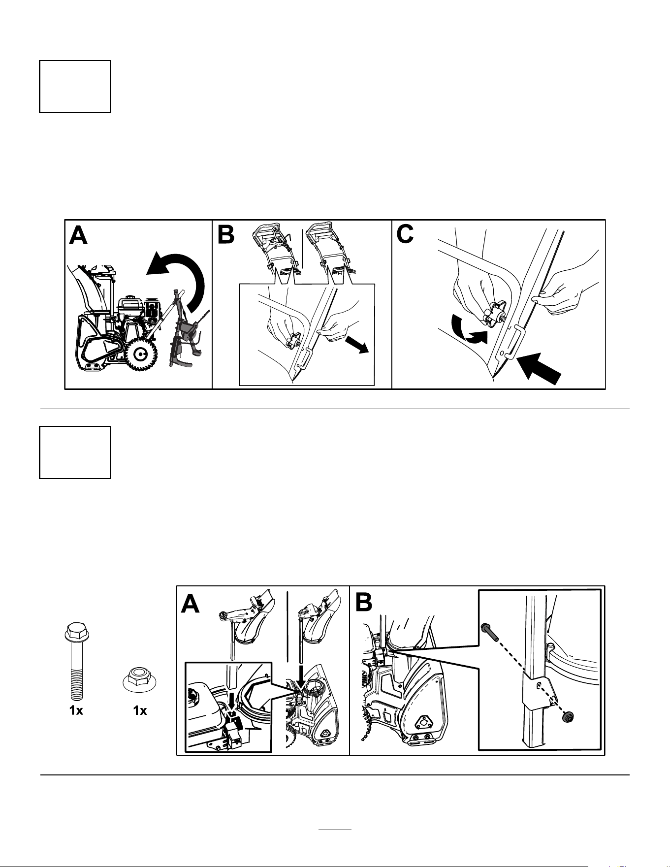
1
Unfolding the Handle
No Parts Required
Procedure
g257569
2
Installing the Discharge Chute
No Parts Required
Procedure
g257570
5
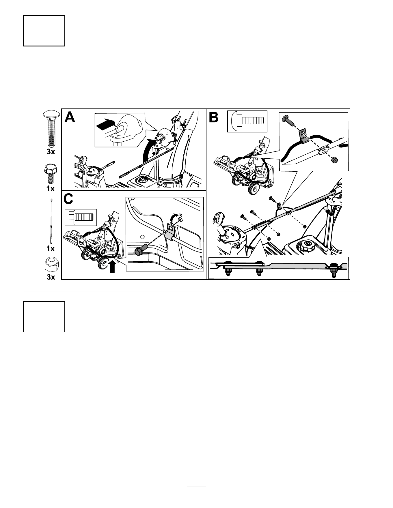
3
Installing the Chute-Control Rod
No Parts Required
Procedure
g257571
4
Checking the Engine-Oil Level
No Parts Required
Procedure
Note: Your machine comes with oil in the engine crankcase. Before starting the engine, check the oil level
and add oil if necessary.
Refer to Checking the Engine-Oil Level (page 10).
6
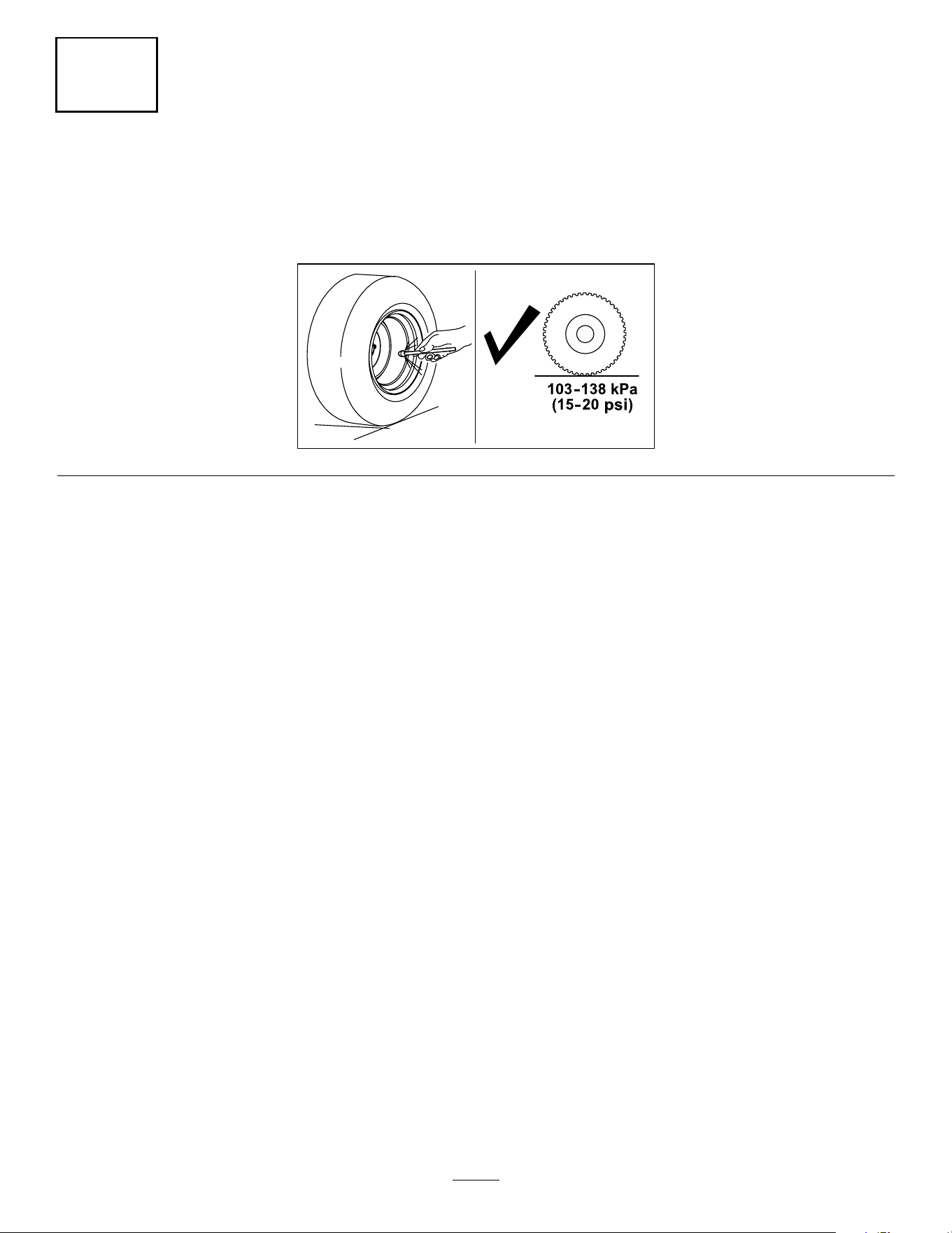
5
Adjusting the Tire Pressure
No Parts Required
Procedure
g211051
7
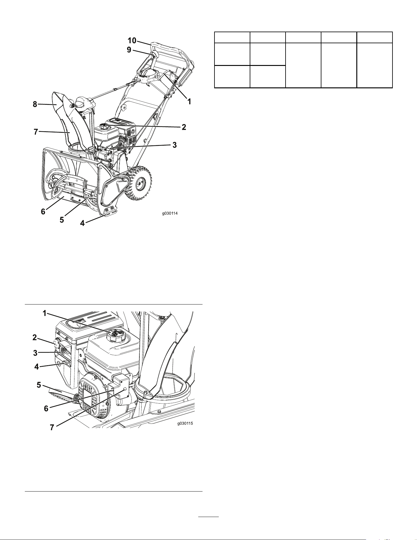
Product Overview
g030114
Figure 8
1. Auger lever
6. Scraper
2. Fuel-tank cap 7. Discharge chute
3. Dipstick
8. Chute deector
4. Skid (2) 9. Quick Stick®
discharge-chute control
5. Auger 10. Upper handle
g030115
Figure 9
1. Fuel-tank cap 5. Recoil-start handle
2. Primer 6. Electric-start plug-in
3. Key 7. Electric-start button
4. Choke
Specications
Model Weight Length Width Height
56.7 kg
36002
(125 lb) 132 cm 65 cm 108 cm
59.4 kg
36003
(131 lb)
(52
inches)
(25
inches)
(43
inches)
Attachments/Accessories
A selection of Toro approved attachments and
accessories is available for use with the machine
to enhance and expand its capabilities. Contact
your Authorized Service Dealer or authorized Toro
distributor or go to www.Toro.com for a list of all
approved attachments and accessories.
To ensure optimum performance and continued safety
certication of the machine, use only genuine Toro
replacement parts and accessories. Replacement
parts and accessories made by other manufacturers
could be dangerous, and such use could void the
product warranty.
Operation
Note: Determine the left and right sides of the
machine from the normal operating position.
Before Operation
Before Operation Safety
General Safety
• For electric-start models only: Use extension
cords and receptacles as specied in the manual.
Inspect the electrical cord before plugging it into
a power source. If the cord is damaged, replace
it. Unplug the power cord whenever you are not
starting the machine.
• Wear appropriate clothing, including eye
protection; long pants; substantial, slip-resistant
footwear; and hearing protection. Tie back long
hair, secure loose clothing, and do not wear loose
jewelry.
• Thoroughly inspect the area where you will use the
machine, and remove all doormats, sleds, boards,
wires, and other foreign objects.
• If a shield, safety device, or decal is damaged,
illegible, or missing, repair or replace it before
beginning operation. Also, tighten any loose
fasteners.
8
Fuel Safety
Fuel is extremely ammable and explosive. A re or
explosion from fuel can burn you and others.
• To prevent a static charge from igniting the fuel,
place the container and/or machine on the ground
before lling, not in a vehicle or on an object.
• Fill the fuel tank outdoors when the engine is cold.
Replace the fuel cap securely and wipe up spills.
• Do not handle fuel when smoking or around an
open ame or sparks.
• Store fuel in an approved fuel container, out of the
reach of children.
• When fuel is in the tank, tip the machine only as
directed in the instructions.
• If you spill fuel on your clothing, change your
clothing immediately.
Filling the Fuel Tank
• For best results, use only clean, fresh (less than
30 days old), unleaded gasoline with an octane
rating of 87 or higher ((R+M)/2 rating method).
• Oxygenated fuel with up to 10% ethanol or 15%
MTBE by volume is acceptable.
• Do not use ethanol blends of gasoline (such
as E15 or E85) with more than 10% ethanol by
volume. Performance problems and/or engine
damage may result which may not be covered
under warranty.
• Do not use gasoline containing methanol.
• Do not store fuel either in the fuel tank or fuel
containers over the winter unless you use a fuel
stabilizer.
• Do not add oil to gasoline.
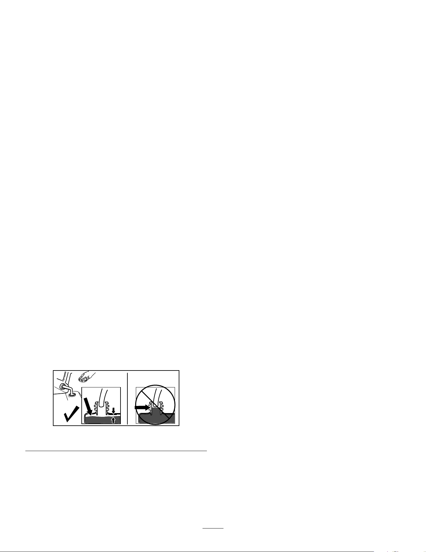
Do not ll above the bottom of the fuel tank neck
(Figure 10).
g216203
Figure 10
Important: For best results, purchase only the
quantity of fuel that you expect to use in 30 days.
Otherwise, you may use fuel stabilizer/conditioner
in the machine at all times to keep the fuel fresh
longer when used as directed by the fuel-stabilizer
manufacturer.
9
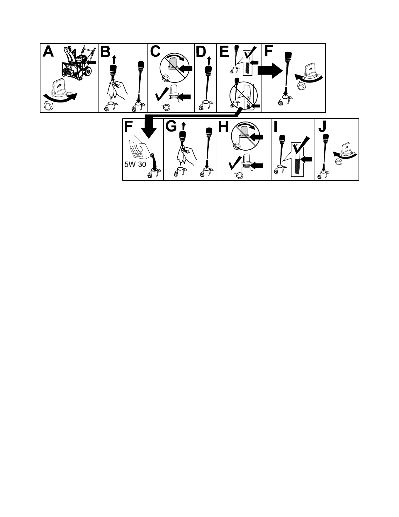
Checking the Engine-Oil Level
Service Interval: Before each use or daily
g257572
Figure 11
During Operation
During Operation Safety
General Safety
• Shut off the engine before unclogging the
machine and always use a stick.
• Stay behind the handles and away from the
discharge opening while operating the machine.
Keep your face, hands, feet, and any other part
of your body or clothing away from moving or
rotating parts.
• Never direct the discharge toward people or areas
where property damage can occur.
• Use your full attention while operating the
machine. Do not engage in any activity that
causes distractions; otherwise, injury or property
damage may occur.
• Exercise caution to avoid slipping or falling,
especially when operating the machine in reverse.
• Always be sure of your footing, and keep a rm
hold on the handles. Walk; never run.
• Exercise extreme caution when operating the
machine on a slope.
• Do not operate the machine without good visibility
or light.
• Look behind and use care when backing up the
machine.
• When not actively clearing snow, disengage power
to the auger.
• Exercise extreme caution when operating the
machine on walks or roads. Stay alert for hidden
hazards or trafc.
• Never attempt to make any adjustments while
the engine is running, except as directed in the
instructions.
• After striking a foreign object, shut off the engine,
remove the key, and inspect the machine for
damage. Repair any damage before starting the
machine.
• If the machine starts to vibrate abnormally, shut off
the engine and check immediately for the cause.
• Do not run the engine indoors; exhaust fumes are
dangerous.
• Do not overload the machine capacity by
attempting to clear snow at too fast a rate.
• Shut off the engine whenever you leave the
operating position, before clearing or unclogging
the collector, rotor, or discharge chute, and when
making any repairs, adjustments, or inspections.
10
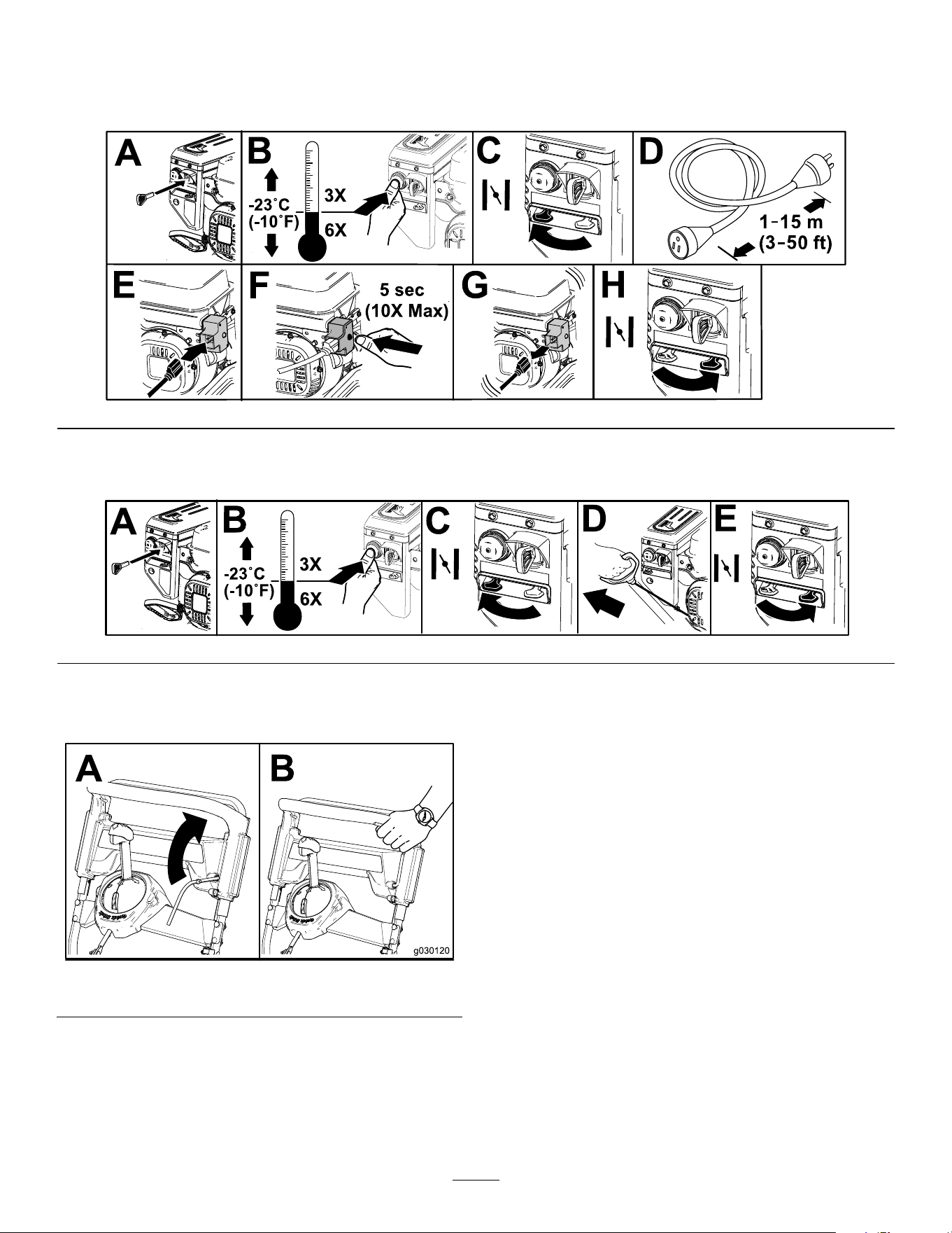
Starting the Engine
Using the Electric Starter
g261846
Using the Recoil Starter
g261847
Engaging the Auger
g030120
Figure 14
Disengaging the Auger
To disengage the auger, release the auger lever.
11
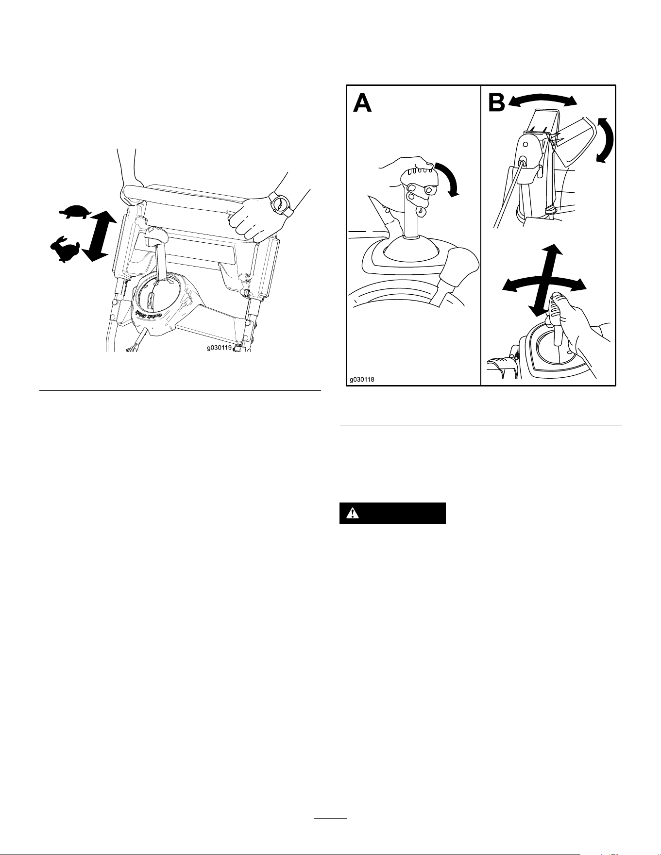
Self-Propelling the Machine
To operate the self-propel drive, simply walk with your
hands on the upper handle and your elbows at your
sides, and the machine automatically keeps pace with
you (Figure 15).
Note: You can self-propel the machine with the auger
engaged or disengaged.
g030119
Figure 15
Shutting Off the Engine
To shut off the engine, remove the key from the
ignition or move the key to the middle position.
Operating the Quick Stick®
Note: Fully press the blue knob to release the latch
and operate the Quick Stick®.
g030118
Figure 16
Clearing a Clogged
Discharge Chute
WARNING
If the auger/impeller is running but there is no
snow coming out of the discharge chute, the
discharge chute may be clogged.
Never use your hands to clear a clogged
discharge chute. This could result in personal
injury.
1. While remaining in the operating position,
release the self-propel handle.
2. Engage the auger.
3. Push down on the handle to raise the front of
the machine a few centimeters (inches) off the
pavement, then lift the handles quickly to bump
the front of the machine onto the pavement.
4. Disengage the auger.
5. Repeat steps 1 through 4, if necessary, until
a stream of snow comes out of the discharge
chute.
12

Important: If you cannot unclog the discharge
chute by bumping the front of the machine, shut
off the engine, wait for all moving parts to stop,
and use a snow-cleanout tool (not included).
Important: Unclogging the discharge chute
by bumping the front of the machine on the
pavement may cause the skids to move. Adjust
the skids and tighten the skid bolts securely; refer
to Checking and Adjusting the Skids (page 14).
Operating Tips
WARNING
The auger can throw stones, toys, and other
foreign objects and cause serious personal
injury to you or bystanders.
• Keep the area to be cleared free of all
objects that the rotor blades could pick up
and throw.
• Keep all children and pets away from the
area of operation.
•
Remove the snow as soon as possible after it falls.
• Overlap each swath to ensure complete snow
removal.
• Discharge the snow downwind whenever possible.
• If the machine does not propel itself forward on
slippery surfaces or in heavy snow, push forward
on the handle, but allow the machine to work at
its own pace.
After Operation
After Operation Safety
General Safety
• Never store the machine with fuel in the fuel
tank inside a building where ignition sources are
present, such as hot water heaters, space heaters,
or clothes dryers. Allow the engine to cool before
storing the machine in any enclosure.
• When storing the machine for more than 30
days, refer to Storage (page 19) for important
information.
• Run the machine a few minutes after throwing
snow to prevent freeze-up of the collector and
rotor.
Preventing Freeze-up after
Use
• Let the engine run for a few minutes to prevent
moving parts from freezing. Shut off the engine,
wait for all moving parts to stop, and remove ice
and snow from the machine.
• Clean off any snow and ice from the base of the
chute. Always use a tool to clean snow out of a
chute, never use your hand.
• Rotate the discharge chute left and right to free
it from any ice buildup.
• Remove the key, pull the recoil-start handle
several times or connect the electrical cord to
a power source and the machine and push the
electric-start button once to prevent the recoil
starter and/or the electric starter from freezing up
(electric-start models only).
• In snowy and cold conditions, some controls and
moving parts may freeze. Do not use excessive
force when trying to operate frozen controls. If you
have difculty operating any control or part, start
the engine and let it run for a few minutes.
• Do not use the chute control to attempt to move a
frozen discharge chute. Hold down the blue knob
and use your hands to rotate the chute.
• Transporting the machine in an open trailer or
vehicle can cause the controls or discharge chute
to freeze.
13

Maintenance
Recommended Maintenance Schedule(s)
Maintenance Service
Interval
Maintenance Procedure
After the rst hour
• Check for loose fasteners and tighten them if necessary.
After the rst 2 hours
• Change the engine oil.
• Inspect the auger cable and adjust it if necessary.
• Inspect the transmission cable and adjust it if necessary.
Before each use or daily
• Check the engine-oil level and add oil if necessary.
Every 100 hours
• Replace the spark plug.
Yearly
• Check the skids and adjust them if necessary.
• Inspect the throwing edges and have an Authorized Service Dealer replace the
throwing edges and scraper if necessary.
• Change the engine oil.
• Inspect the auger cable and adjust it if necessary.
• Inspect the transmission cable and adjust it if necessary.
• Check for loose fasteners and tighten them if necessary.
• Have an Authorized Service Dealer inspect the drive belt and replace it if necessary.
Yearly or before storage
• Prepare the machine for storage.
Maintenance Safety
Read the following safety precautions before
performing any maintenance on the machine:
• Shut off the engine, remove the key, and wait
for all movement to stop before you leave the
operator’s position. Allow the machine to cool
before adjusting, servicing, cleaning, or storing it.
• Always wear eye protection while performing an
adjustment or repair to protect your eyes from
foreign objects that the machine may throw.
• Check all fasteners at frequent intervals for proper
tightness to ensure that the machine is in safe
working condition.
• Do not change the governor settings on the engine.
Purchase only genuine Toro replacement parts
and accessories.
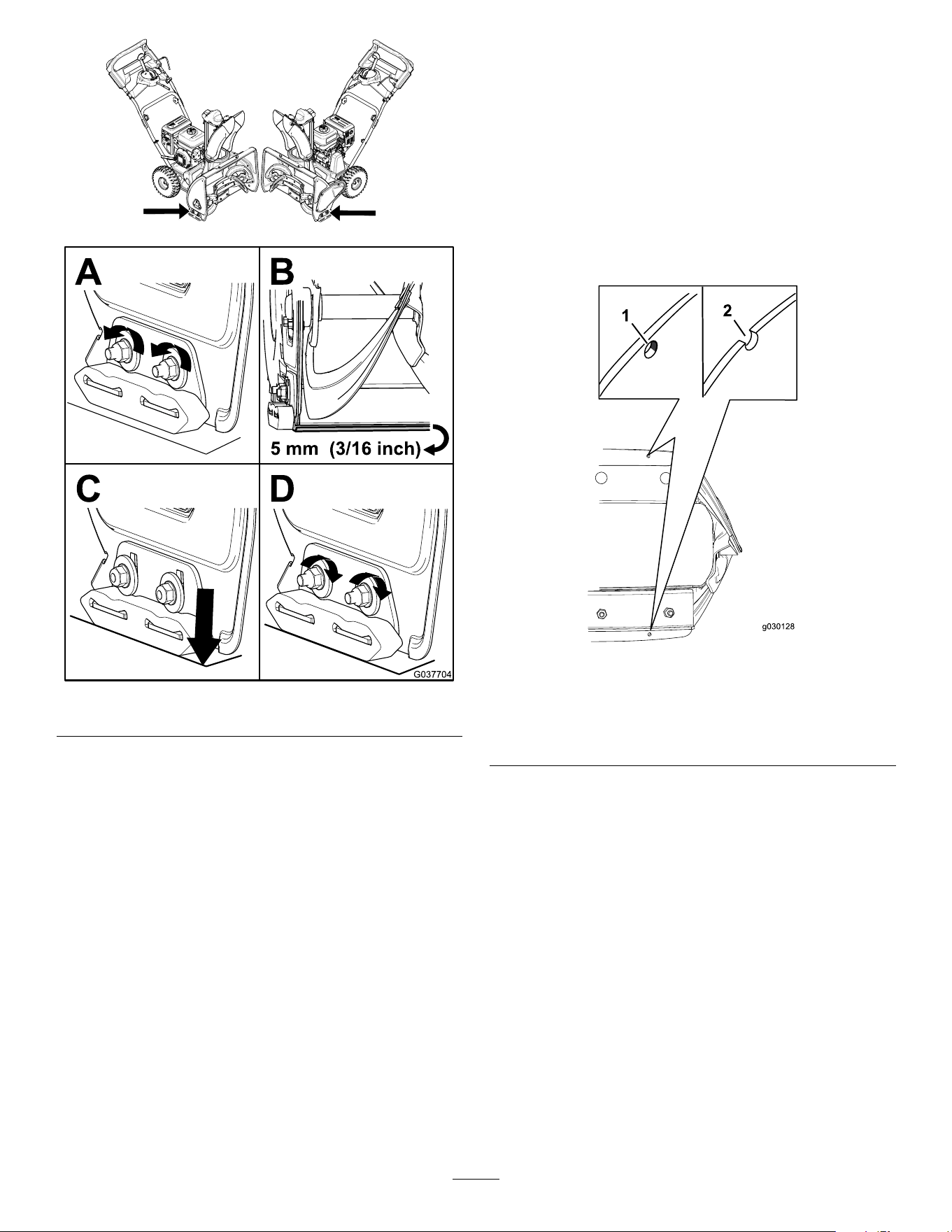
Checking and Adjusting the
Skids
Service Interval: Yearly
Check the skids to ensure that the auger does not
contact the paved surface. Adjust the skids as needed
to compensate for wear (Figure 17).
1. Loosen the skid bolts.
2. Slide a 5 mm (3/16 inch) board underneath the
scraper.
Note: Using a thinner board results in a more
aggressive scraper; using a thicker board results
in a less aggressive scraper.
3. Lower the skids to the ground.
Note: Ensure that the skids are at on the
ground.
4. Tighten the skid bolts.
14
g218004
g037704
Figure 17
Inspecting the Throwing
Edges
Service Interval: Yearly—Inspect the throwing edges
and have an Authorized Service
Dealer replace the throwing edges
and scraper if necessary.
Before each session, inspect the throwing edges
for wear. When a throwing edge has worn down to
the wear-indicator hole, have an Authorized Service
Dealer replace the throwing edges (Figure 18).
g030128
Figure 18
1. The wear-indicator hole
is intact; you do not need
to replace the throwing
edges.
2. The wear-indicator hole
is exposed; replace both
throwing edges.
15
Changing the Engine Oil
Service Interval: After the rst 2 hours
Yearly
If possible, run the engine for a few minutes before
changing the oil to warm it. Warm oil ows better and
carries more contaminants.
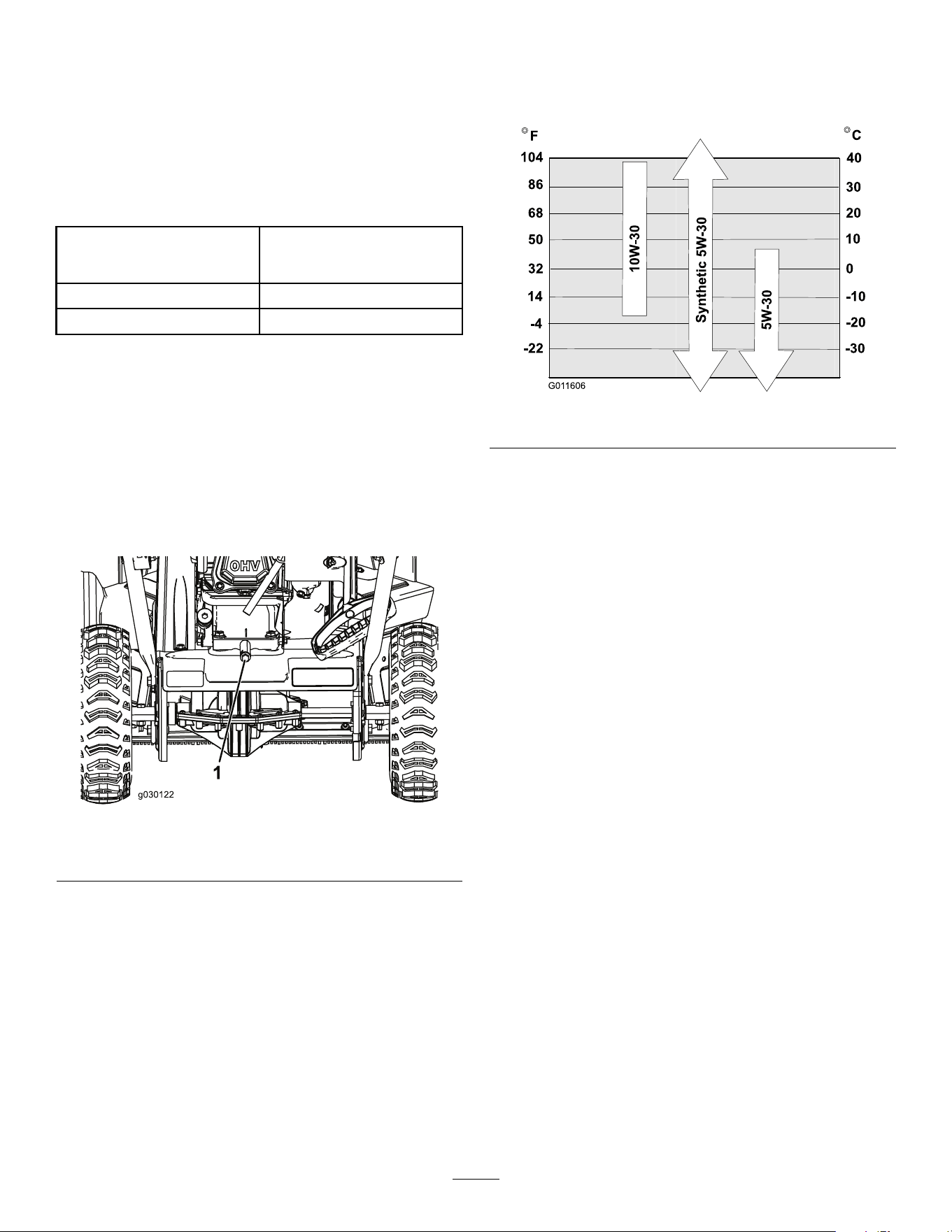
Engine Oil Specications
Engine oil capacity
Model 36002: 0.60 L (20
oz); Model 36003: 0.70 L (24
oz)*
Oil viscosity Refer to Figure 20.
API service classication SJ or higher
*There is residual oil in the crankcase after you drain
the oil. Do not pour the entire capacity of oil into the
crankcase. Fill the crankcase with oil as directed in
the following steps.
Use Figure 20 to select the best oil viscosity for the
outdoor temperature range expected:
1. Move the machine to a level surface.
2. Clean the area around the oil-drain plug (Figure
19).
g030122
Figure 19
1. Oil-drain plug
3. Place an oil-drain pan under the oil-drain plug,
remove the oil-drain plug, and tip the machine
backward and drain the used oil in the oil-drain
pan (Figure 19).
Note: Dispose of the used oil properly at a local
recycling center.
4. After draining the used oil, return the machine to
the operating position.
5. Install the oil-drain plug and tighten it securely.
6. Clean around the oil-ll/dipstick and remove the
dipstick.
7. Carefully pour about 3/4 of the engine capacity
of oil into the oil-ll tube. Use
Figure 2 to select
the best oil viscosity for the outdoor temperature
range expected:
g011606
Figure 20
8. Wait 3 minutes for the oil to settle in the engine.
9. Wipe the dipstick clean with a clean cloth.
10. Insert the dipstick into the oil-ll tube, do not
screw it in, then remove the dipstick.
11. Read the oil level on the dipstick.
• If the oil level on the dipstick is too low,
carefully pour a small amount of oil into the
oil-ll tube, wait 3 minutes, and repeat steps
9 through 11 until the oil level on the dipstick
is correct.
• If the oil level on the dipstick is too high,
drain the excess oil until the oil level on the
dipstick is correct.
Important: If the oil level in the engine is too
low or too high and you run the engine, you
may damage the engine.
12. Install the dipstick into the oil-ll tube securely.
13. Recycle the used oil properly.
16
Replacing the Spark Plug
Service Interval: Every 100 hours—Replace the
spark plug.
WARNING
Replacing the spark plug while the engine is
hot can result in burns.
Wait until the engine is cool to replace the
spark plug.
Use a Toro spark plug or equivalent (Champion®
RN9YC or NGK BPR6ES).
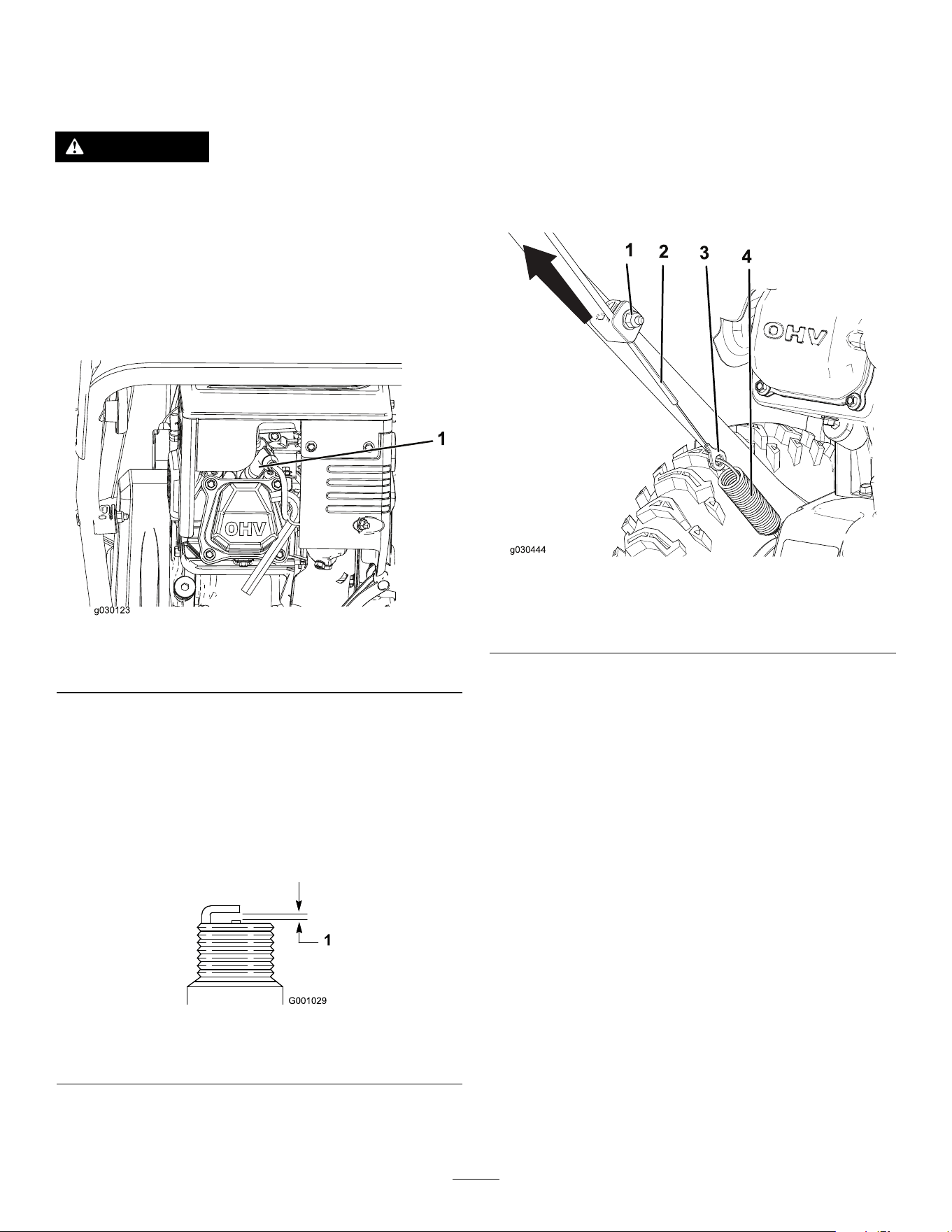
1. Remove the boot (Figure 21).
g030123
Figure 21
1. Spark-plug boot
2. Clean around the base of the spark plug.
3. Remove and discard the old spark plug.
Note: You will need a ratchet wrench extension
to remove the spark plug.
4. Set the gap between the electrodes on a new
spark plug at 0.76 mm (0.030 inch) as shown
in Figure 22.
g001029
Figure 22
1. 0.76 mm (0.030 inch)
Adjusting the Auger Cable
Service Interval: After the rst 2 hours
Yearly
If the drive belt slips or squeals under a heavy load,
adjust the auger cable.
1. Loosen the nut on the lower cable clamp, but do
not remove it (Figure 23).
g030444
Figure 23
1. Nut
3. Connector
2. Cable 4. Spring
2. Pull the cable up to remove some slack (Figure
23).
Important: Do not remove all the slack
from the cable. Removing all the slack from
the cable prevents the auger from stopping
properly.
3. Hold the cable in place and tighten the nut
(Figure 23).
17
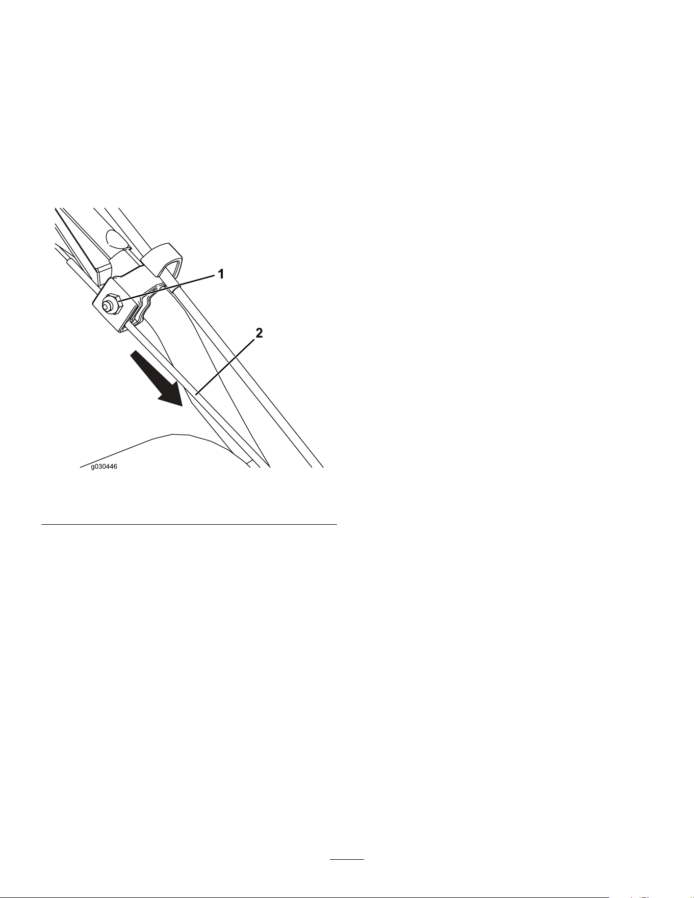
Adjusting the Transmission
Cable
Service Interval: After the rst 2 hours
Yearly
If the wheels easily stall out, or if the wheels drive
without engaging the self-propel handle, adjust the
transmission cable.
1. Loosen the nut on the upper cable clamp, but do
not remove it (Figure 24).
g030446
Figure 24
1. Nut
2. Cable
2. Pull the cable down to remove most of the slack
in the cable (Figure 24).
Important: Do not remove all the slack
from the cable. Removing all the slack from
the cable may cause the wheels to engage
without engaging the self-propel handle.
3. Tighten the nut (Figure 24).
18

Storage
Storage Safety
• Shut off the engine, remove the key, and wait
for all movement to stop before you leave the
operator’s position. Allow the machine to cool
before adjusting, servicing, cleaning, or storing it.
• Fuel fumes are highly ammable, explosive, and
dangerous if inhaled. If you store the product in an
area with an open ame, the fuel fumes may ignite
and cause an explosion.
• Do not store the machine in a house (living
area), basement, or any other area where ignition
sources may be present, such as hot water and
space heaters, clothes dryers, furnaces, and other
appliances.
• Do not tip the machine either forward or backward
with fuel in the fuel tank; otherwise, fuel may leak
out of the machine.
• Do not store the machine with its handle tipped
down onto the ground; otherwise, oil may leak into
the engine cylinder and onto the ground, and the
engine may not start.
Storing the Machine
1. On the last refueling of the season, add fuel
stabilizer to fresh fuel as directed by the
fuel-stabilizer manufacturer.
Important: Do not store fuel longer
than that suggested by the fuel-stabilizer
manufacturer.
2. Run the engine for 10 minutes to distribute the
conditioned fuel through the fuel system.
3. Shut off the engine, allow it to cool, and siphon
the fuel tank or run the engine until it shuts off.
4. Start the engine and run it until it shuts off.
5. Choke or prime the engine, start it a third time,
and run the engine until it does not start.
6. Drain the fuel in the carburetor through the
carburetor-drain bolt into an approved gasoline
container.
7. Dispose of unused fuel properly. Recycle it
according to local codes, or use it in your
automobile.
8. While the engine is still warm, change the engine
oil. Refer to
Changing the Engine Oil (page 16).
9. Remove the spark plug.
10. Squirt 10 ml (2 tsp) of oil into the spark-plug hole.
11. Install the spark plug by hand and then torque it
to 27 to 30 N∙m (20 to 22 ft-lb).
12. With the ignition key removed, pull the
recoil-start handle slowly to distribute the oil on
the inside of the cylinder.
13. Clean the machine.
14. Touch up chipped surfaces with paint available
from an Authorized Service Dealer. Sand
affected areas before painting, and use a rust
preventative to prevent the metal parts from
rusting.
15. Tighten any loose fasteners. Repair or replace
any damaged parts.
16. Cover the machine and store it in a clean, dry
place out of the reach of children. Allow the
engine to cool before storing the machine in any
enclosure.
19

California Proposition 65 Warning Information
What is this warning?
You may see a product for sale that has a warning label like the following:
WARNING: Cancer and Reproductive Harm—www.p65Warnings.ca.gov.
What is Prop 65?
Prop 65 applies to any company operating in California, selling products in California, or manufacturing products that may be sold in or brought into
California. It mandates that the Governor of California maintain and publish a list of chemicals known to cause cancer, birth defects, and/or other
reproductive harm. The list, which is updated annually, includes hundreds of chemicals found in many everyday items. The purpose of Prop 65 is to
inform the public about exposure to these chemicals.
Prop 65 does not ban the sale of products containing these chemicals but instead requires warnings on any product, product packaging, or literature with
the product. Moreover, a Prop 65 warning does not mean that a product is in violation of any product safety standards or requirements. In fact, the
California government has claried that a Prop 65 warning “is not the same as a regulatory decision that a product is ‘safe’ or ‘unsafe.’” Many of these
chemicals have been used in everyday products for years without documented harm. For more information, go to
https://oag.ca.gov/prop65/faqs-view-all
.
A Prop 65 warning means that a company has either (1) evaluated the exposure and has concluded that it exceeds the “no signicant risk level”; or (2)
has chosen to provide a warning based on its understanding about the presence of a listed chemical without attempting to evaluate the exposure.
Does this law apply everywhere?
Prop 65 warnings are required under California law only. These warnings are seen throughout California in a wide range of settings, including but not
limited to restaurants, grocery stores, hotels, schools, and hospitals, and on a wide variety of products. Additionally, some online and mail order
retailers provide Prop 65 warnings on their websites or in catalogs.
How do the California warnings compare to federal limits?
Prop 65 standards are often more stringent than federal and international standards. There are various substances that require a Prop 65 warning
at levels that are far lower than federal action limits. For example, the Prop 65 standard for warnings for lead is 0.5 μg/day, which is well below
the federal and international standards.
Why don’t all similar products carry the warning?
• Products sold in California require Prop 65 labelling while similar products sold elsewhere do not.
• A company involved in a Prop 65 lawsuit reaching a settlement may be required to use Prop 65 warnings for its products, but other companies
making similar products may have no such requirement.
• The enforcement of Prop 65 is inconsistent.
• Companies may elect not to provide warnings because they conclude that they are not required to do so under Prop 65; a lack of warnings for a
product does not mean that the product is free of listed chemicals at similar levels.
Why does Toro include this warning?
Toro has chosen to provide consumers with as much information as possible so that they can make informed decisions about the products they buy and
use. Toro provides warnings in certain cases based on its knowledge of the presence of one or more listed chemicals without evaluating the level of
exposure, as not all the listed chemicals provide exposure limit requirements. While the exposure from Toro products may be negligible or well within the
“no signicant risk” range, out of an abundance of caution, Toro has elected to provide the Prop 65 warnings. Moreover, if Toro does not provide these
warnings, it could be sued by the State of California or by private parties seeking to enforce Prop 65 and subject to substantial penalties.
Rev A
