
REV L DATE: 09/25/2023
USER MANUALS\99425_IMPULSE_USER MANUAL_CSC3223_AMBIENT_SLF-SVC_C'TOP CASE
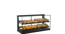
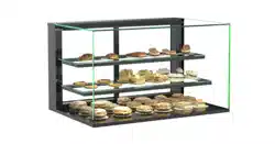
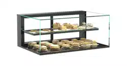
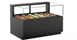
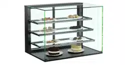
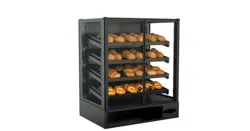
SELF-SERVICE AMBIENT COUNTERTOP UNITS
>> MODELS CSC3223 / CSC3223.4254 / CSC3223.4817
Structural Concepts Corp. ∙ 888 E. Porter Rd ∙ Muskegon, MI 49441 Phone: 231.798.8888 Fax: 231.798.4960 ∙ www.structuralconcepts.com
SCC P/N
99425
USER
MANUAL
IMPULSE
CAREFULLY FOLLOW THESE INSTRUCTIONS
2
TABLE OF CONTENTS
OVERVIEW AND WARNINGS ……………….……………..…………………..…….…………......………
INSTALLATION ……….…………………………………………………………………………………………
START-UP AND OPERATION …….. …..….…………………...……………......…..………………………
MAINTENANCE FUNDAMENTALS: SHELF ASSEMBLY REMOVAL / DECKING REMOVAL ………..
MAINTENANCE FUNDAMENTALS: STD. DOOR MECHANISM / RYOBI DOOR MECHANISM ……..
LIGHT FIXTURES - LED …………………………………………………………………………...………….
TROUBLESHOOTING / CLEANING SCHEDULE …………..………………………….………….………..
ILLUSTRATED PARTS BREAKDOWN……………………………………………………….………………
SERIAL LABEL LOCATION & INFORMATION LISTED / TECH INFO & SERVICE……………...……..
TECHNICAL SERVICE CONTACT INFORMATION & WARRANTY INFORMATION …................……
3
4
5
6
7
8
9
10-13
14
15
CAUTION
3
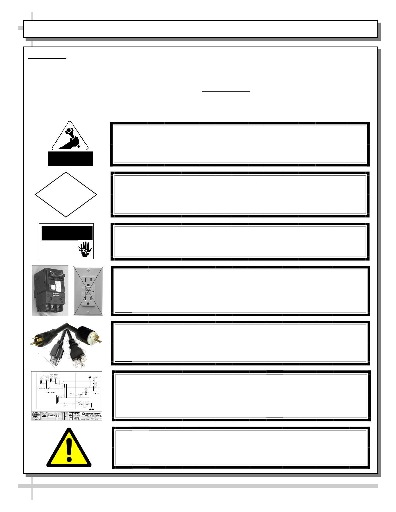
OVERVIEW AND WARNINGS
WARNING
ELECTRICAL
HAZARD
OVERVIEW
• The Structural Concepts non-refrigerated service
cases are designed to merchandise unpackaged
bakery products at ambient temperatures.
• These cases should be installed and operated
according to the following instructions to ensure
proper performance.
WARNING
Risk of electric shock.
Disconnect ALL ELECTRICAL SOURCES before servicing.
CAUTION! LAMP REPLACEMENT GUIDELINES
LED lamps reflect specific size, shape and overall design.
Any replacements must meet factory specifications.
CAUTION! GFCI BREAKER USE REQUIREMENT
If N.E.C. (National Electric Code) or your local code
requires GFCI (Ground Fault Circuit Interrupter) protection,
you MUST use a GFCI breaker in lieu of a GFCI receptacle.
COMPLIANCE
This equipment MUST be installed in compliance with
all applicable NEC, federal, state and local electrical codes.
ATTENTION
CONTRACTORS
CAUTION! POWER CORD AND PLUG MAINTENANCE
Risk of electric shock. If cord or plug becomes damaged,
replace only with cord and plug of same type.
WIRING DIAGRAM FORMAT & LOCATION
• Each case has its own wiring diagram folded & in its own packet.
• Wiring diagram placement may vary; it may be placed near ballast
box, field wiring box, raceway cover, or other related location.
WARNING: This product can expose you to chemicals, including
Urethane (Ethyl Carbamate), which are known to the state of
California to cause cancer and birth defects or other reproductive
harm. For more information go to P65Warnings.ca.gov.
• This unit is designed for the display of products in
ambient store conditions where temperatures and
humidity are maintained at a maximum of 75° F
and 55% relative humidity.
COMPLIANCE
• Performance issues when in violation of
applicable NEC, federal, state and local electrical
codes are not covered by warranty.
3
4
INSTALLATION
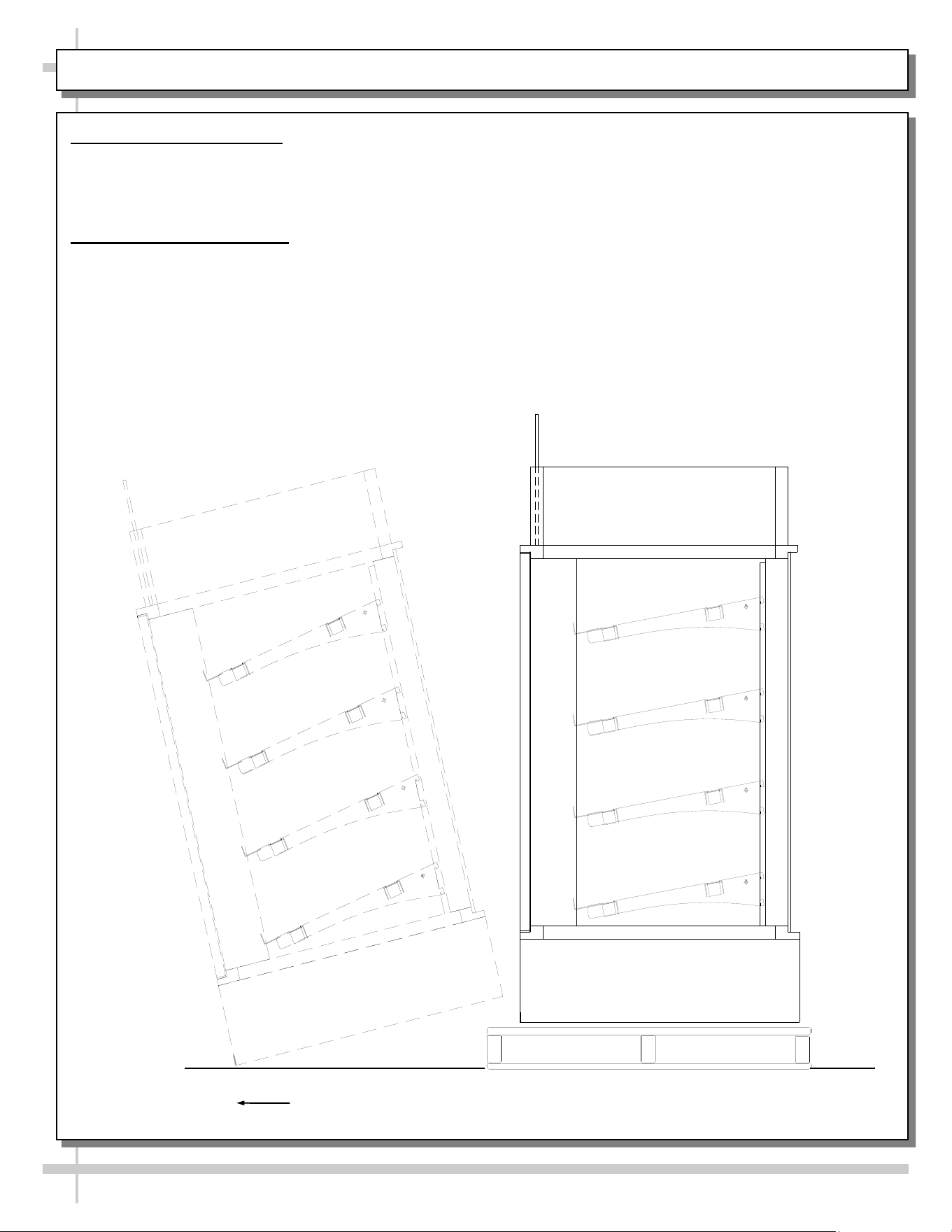
1. Remove Unit From Skid
• Position the unit near a suitable electrical outlet.
• Caution: Case must always remain supported or center of gravity will allow case to fall.
• Slide unit to rear of skid and tip backward off skid.
2. Position and Level Units
For your safety, equipment is furnished with a properly grounded cord connector. Do not attempt to
defeat the grounded connector.
Lift unit with suitable prying bar and blocking. Use care to lift in manner to minimize damage to case.
Rotate leveler to obtain proper height to stabilize and level the unit.
Carefully Slide Unit
Out From Skid
5
START-UP AND OPERATION
For your safety, equipment is furnished with a properly
grounded cord connector. Do not attempt to defeat
the grounded connector.
1. Set-up Counter Top Unit
• Remove case from skid and place on counter in the
position at which the case will reside.
• Note: The following steps must be completed before
this display case may be put in service.
• 1. After case is in position, apply a steady bead of
silicone around the base and counter top.
• 2. Allow 24 hours for the silicone to dry before using
the case.
• Electrical 120V stub up connections are provided in
the light switch box.
2. Merchandiser Start-Up
• Do not use an extension cord with this appliance.
• Do not operate this equipment with a damaged cord,
plug or outlet.
• Insure the power switch is off.
• Plug cord into a certified 120V electrical outlet with
ground.
3. LED Lights Only
• Lights will come on when case is plugged in and light
switch is turned on.
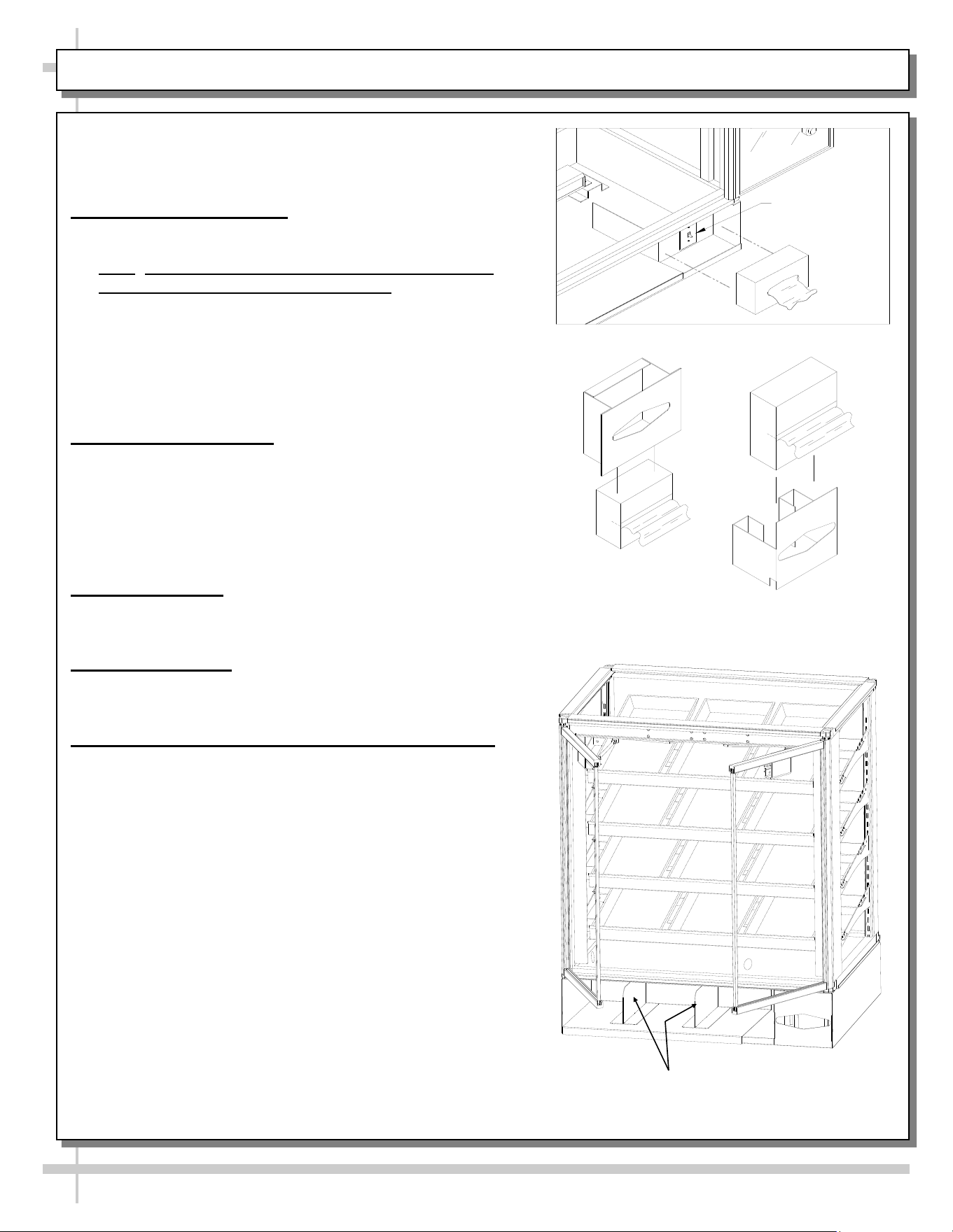
4. Tissue Dispenser
• Remove tissue dispenser.
• Place a tissue box into the dispenser as shown.
5. Adjustable Front Storage Area Dividers (Optional)
• Dividers are held in place with magnetic tape strips.
• Dividers may be adjusted to reflect varying widths.
• Dividers may be entirely removed from case.
Light Switch
—— Tissue Dispensers ——
Adjustable Front Storage Dividers
(Retained With Magnetic Tape)
6
MAINTENANCE FUNDAMENTALS: SHELF ASSEMBLY REMOVAL / DECKING REMOVAL
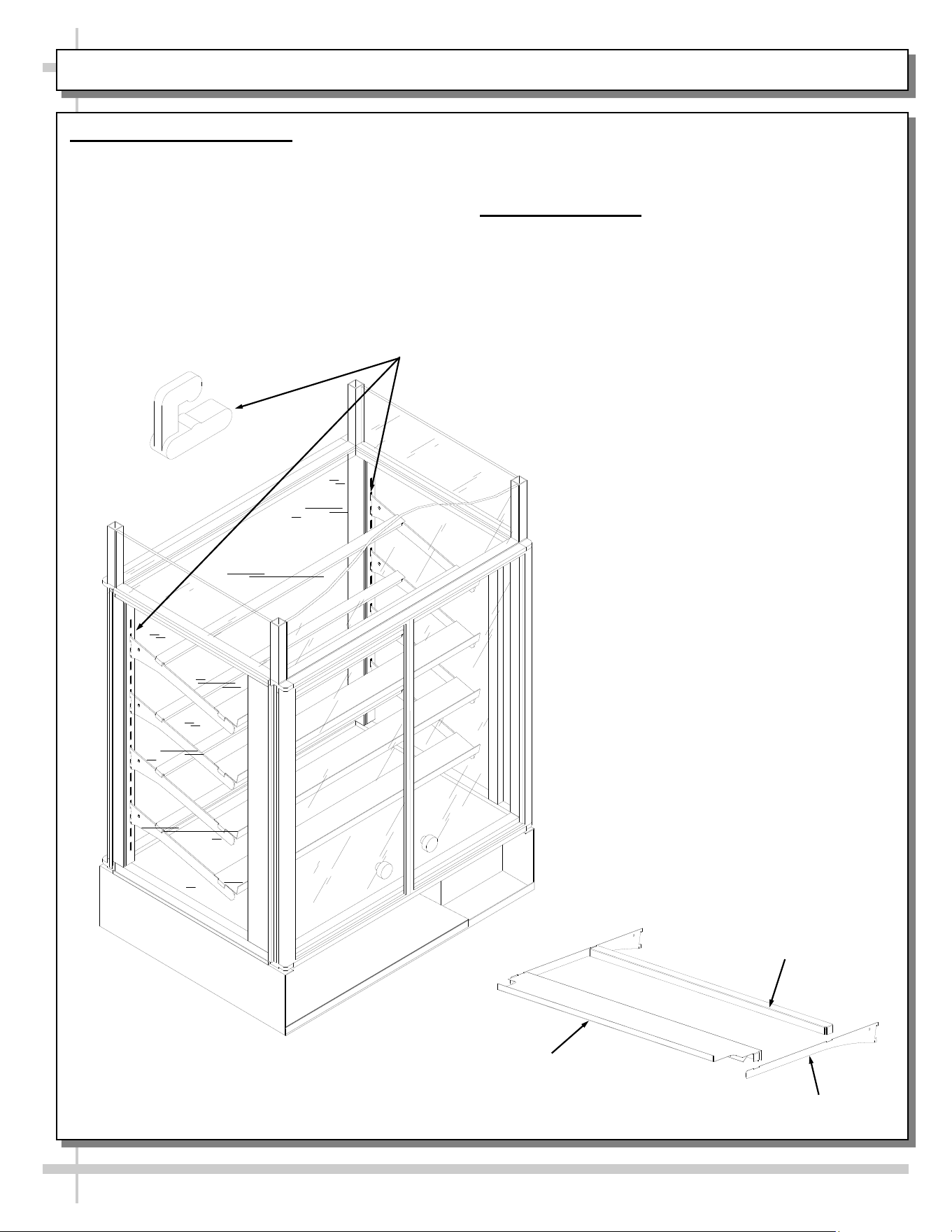
1. Shelf Assembly Removal
• Shelves can be removed for repositioning,
removal (for individual merchandising
requirements) and cleaning.
• Slide the front shelf support back rotate up and
lift straight up to separate from brackets.
• Slide the rear shelf support back rotate up and
lift straight up to separate from brackets.
Bracket Retainer [Typical]
• Remove brackets. Note: It may be necessary to
remove the nylon shipping bracket retainers.
Pliers will be required to accomplish this task.
2. Decking Removal
• Remove lower shelf assembly.
• Remove interior deck by pushing up from
underneath in the bag storage area.
• See illustration at lower right.
Front Shelf Support
Rear Shelf Support
Shelf Bracket
7
MAINTENANCE FUNDAMENTALS: STANDARD DOOR MECHANISM / RYOBI DOOR MECHANISM
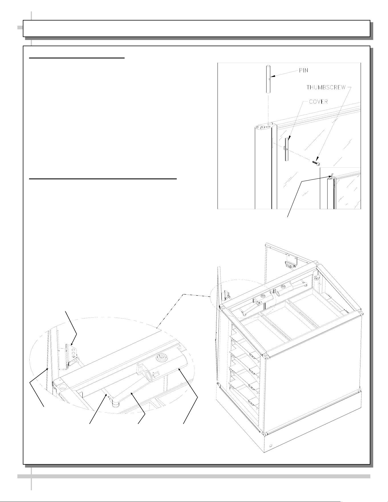
1. Door “Hold Open” Feature
To reposition the shelving or restock the shelves, it is
first helpful to use the door ‘hold open” feature.
• Open the door all the way (See light fixture).
• Caution damage will result if pin is not
lowered before attempting to close the doors.
• Inside the unit, at the top of each door hinge, is
the pin slide cover.
• Slide the pin cover up until the pin extends
approximately 1/2 inch above the door hinge.
• Release the door assembly allowing the pin to rest
on the outer door frame.
• To close, fully open the door and retract the pin into
the hinge and allow the door to close.
2. Ryobi Door Closing Mechanism (Optional)
• Certain models (such as CDR4817) use the Ryobi
door closing mechanism.
• When opened approximately 90°, door ‘catches’
and stays open.
• When pressure is applied to close door, ‘catch’
releases and door closes normally.
PIN EXTENSION
Ryobi Door
Closing
Mechanism
Ryobi Inner
Arm
Ryobi Outer
Arm
Ryobi Pivot
Bracket
Door
8
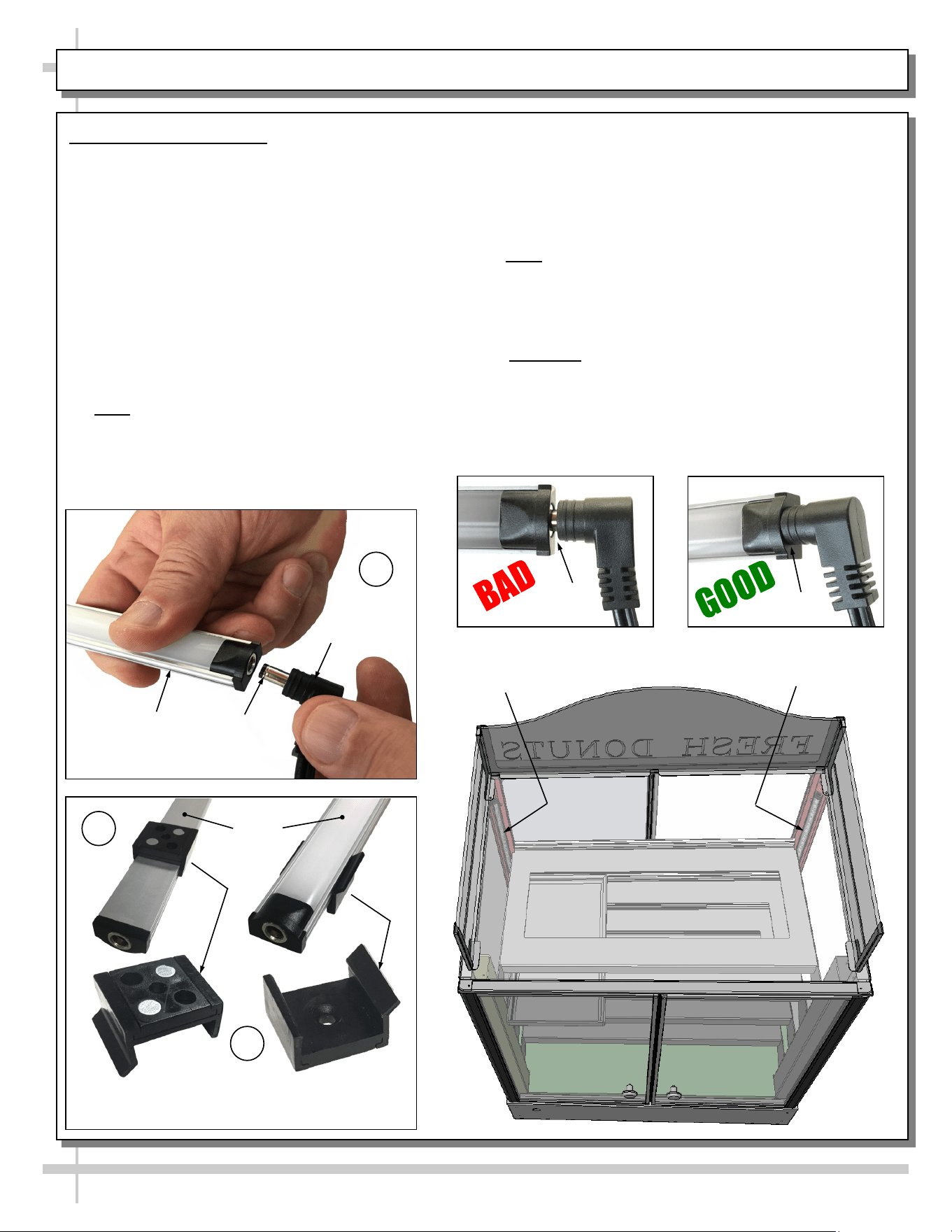
LIGHT FIXTURES - LED
Magnetic Mounting
Clip View #2
LED
Lights
B
A
Plug
Barrel
Shaped
Insert
LED
Light
C
Magnetic Mounting
Clip View #1
No Gap
LED Style Light Fixtures
Removal of Faulty LED Lights:
• LED lights rarely require change-out.
• Contact Structural Concepts’ Technical Service
Department for replacement LED lights.
• Turn off LED light switch.
• To remove faulty LED light, follow these steps:
A. Disconnect plug from LED light.
B. Using both hands, grasp LED light assembly
(with its magnetic mounting clips). Pull
downward and off its shelf (or header).
C. Remove magnetic mounting clips from LED
light by pressing against flange part of clip
with thumb.
>> Note: Mounting clips MAY be riveted to shelf or
header. In such instances, simply remove LED light
from mounting clips by pressing against flange part
of clips with thumb.
Gap
Replacement of LED lights:
• Attach magnetic mounting clips onto LED light.
• Adjust magnetic mounting clips so they are equally
spaced on LED light.
• Reattach LED light assembly to its shelf/header.
• Position properly in shelf/header.
>> Note: If mounting clips are riveted to shelf (or
header), attach by placing LED in base of clip and
then snapping into clip at FLANGE SIDE.
• Press plug’s barrel-shaped insert all the way into
LED light.
• Important: If plug is not inserted ALL THE WAY IN
the LED light’s orifice, the light may not energize.
See “BAD” vs. “GOOD” insertion illustrations
below-right.
• Turn LED light switch back on.
LED Light
LED Light
9
TROUBLESHOOTING / CLEANING SCHEDULE
Issue Resolution
Case Lights Not Working Check LED lights for proper installation and connection. See
LIGHT FIXTURES - LED section in manual for illustrations.
Check for burned out LED lights.
System is not Operating Confirm the utility power is on.
Check the circuit breaker box for tripped circuits.
Troubleshooting
Cleaning Schedule
Cleaning Daily Weekly Monthly Task
Clean Case Exterior X
Clean all case exterior surfaces with a household or
commercial glass cleaner and a soft cloth.
Clean Case Interior X
Clean the interior case deck and shelving surfaces
with a warm water and mild soap solution.
10
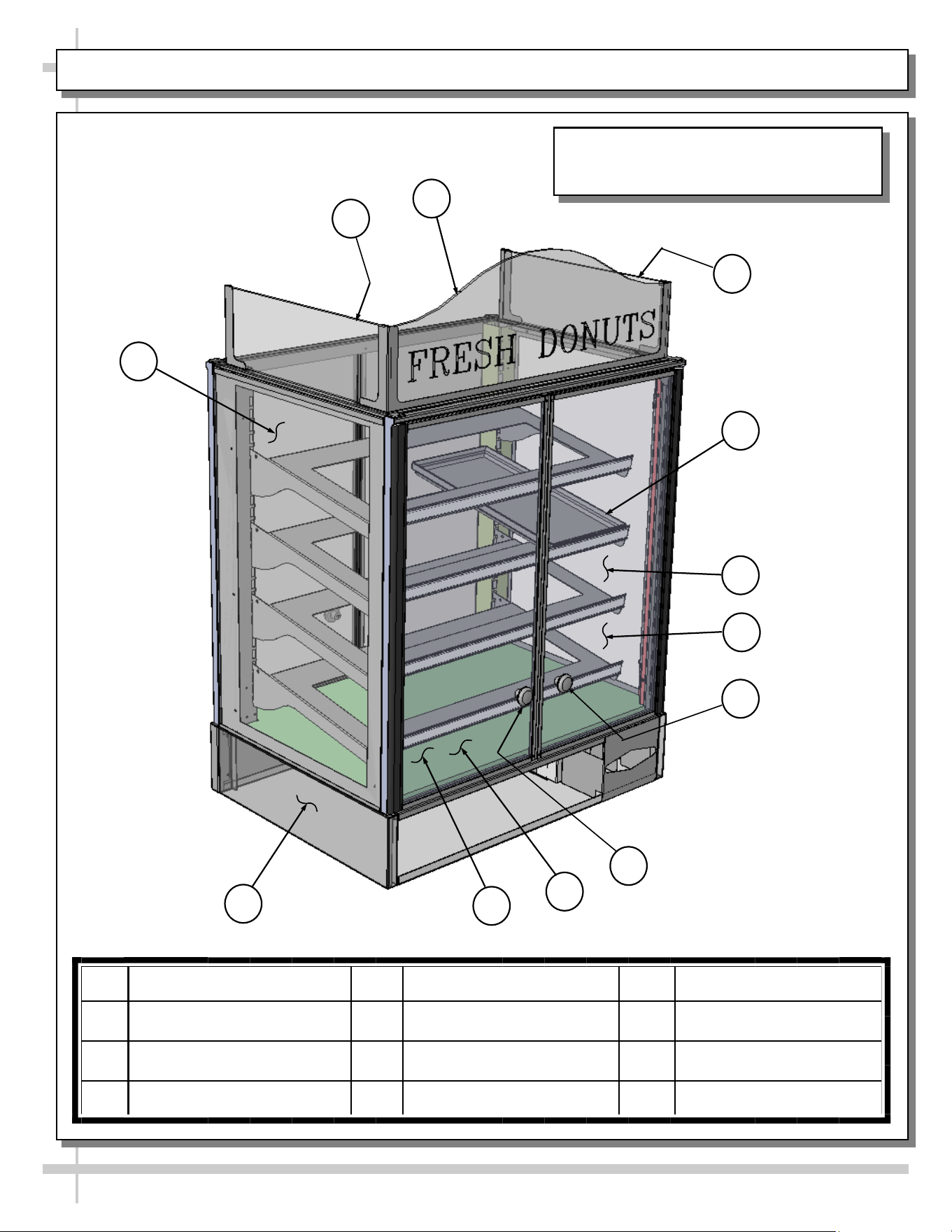
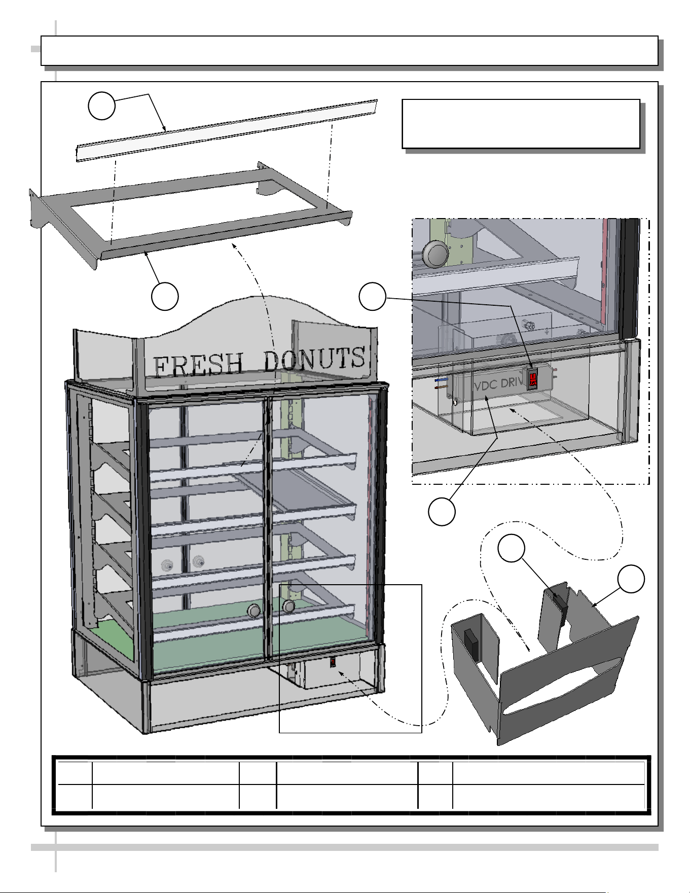
ILLUSTRATED PARTS BREAKDOWN
2
4
12
5
11
1
3
Note: Depending Upon Features And
Options Chosen, Illustration Shown May
Not Exactly Reflect Your Particular Case.
10
9
8
7
1 Header_Sign_Upper_End 5 Exterior_Glass_End_Right 9 Deck_Base_Wood
2 Header_Sign_Upper_Left 6 Door_Glass_Frt_Right 10 Door_Glass_Frt_Left
3 Header_Sign_Upper_Right 7 Knob_Door_Plastic_Right 11 Frame_Base
4 Bin_Tray_Shelf_Fiberglas 8 Knob_Door_Plastic_Left 12 Exterior_Glass_End_Left
6
11
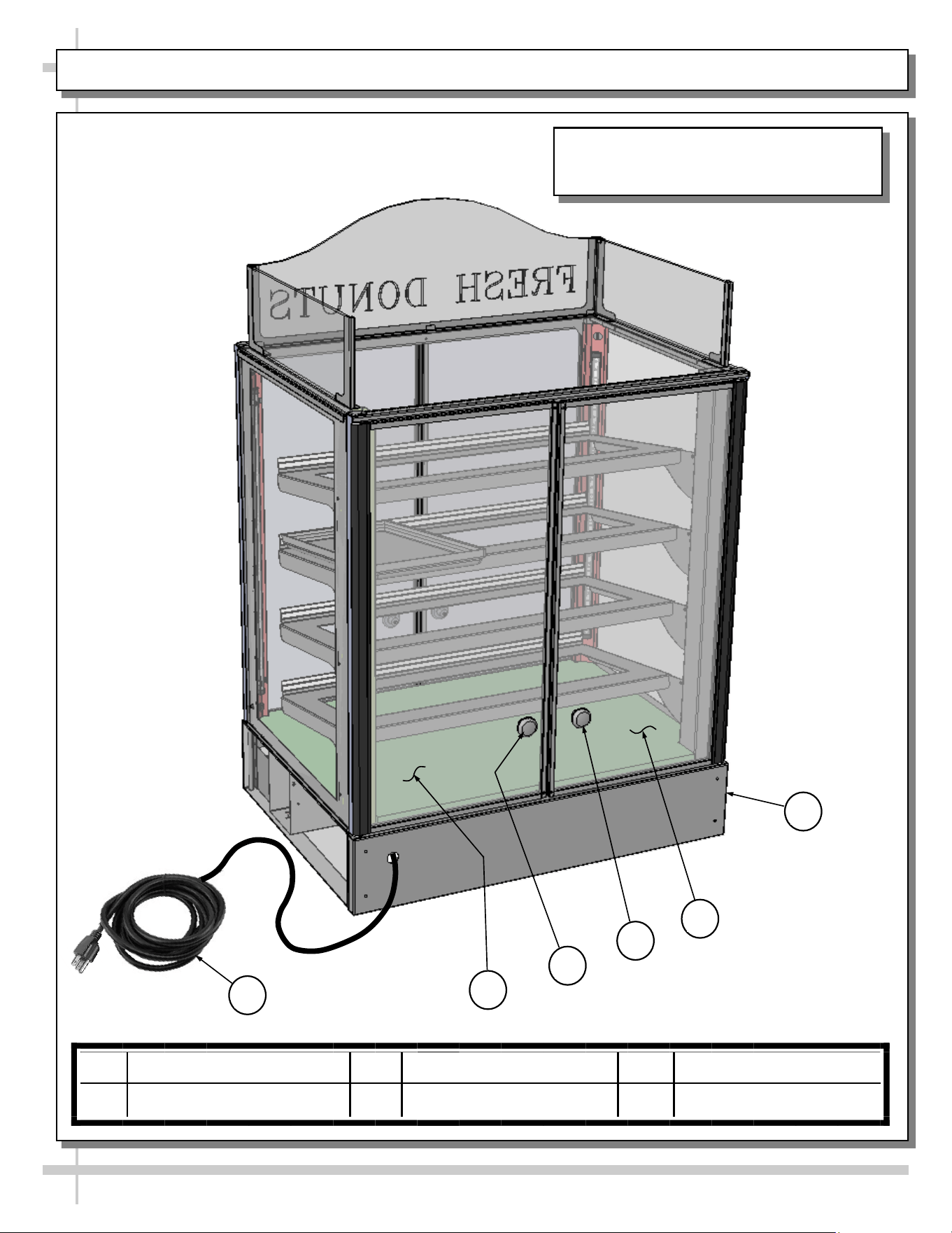
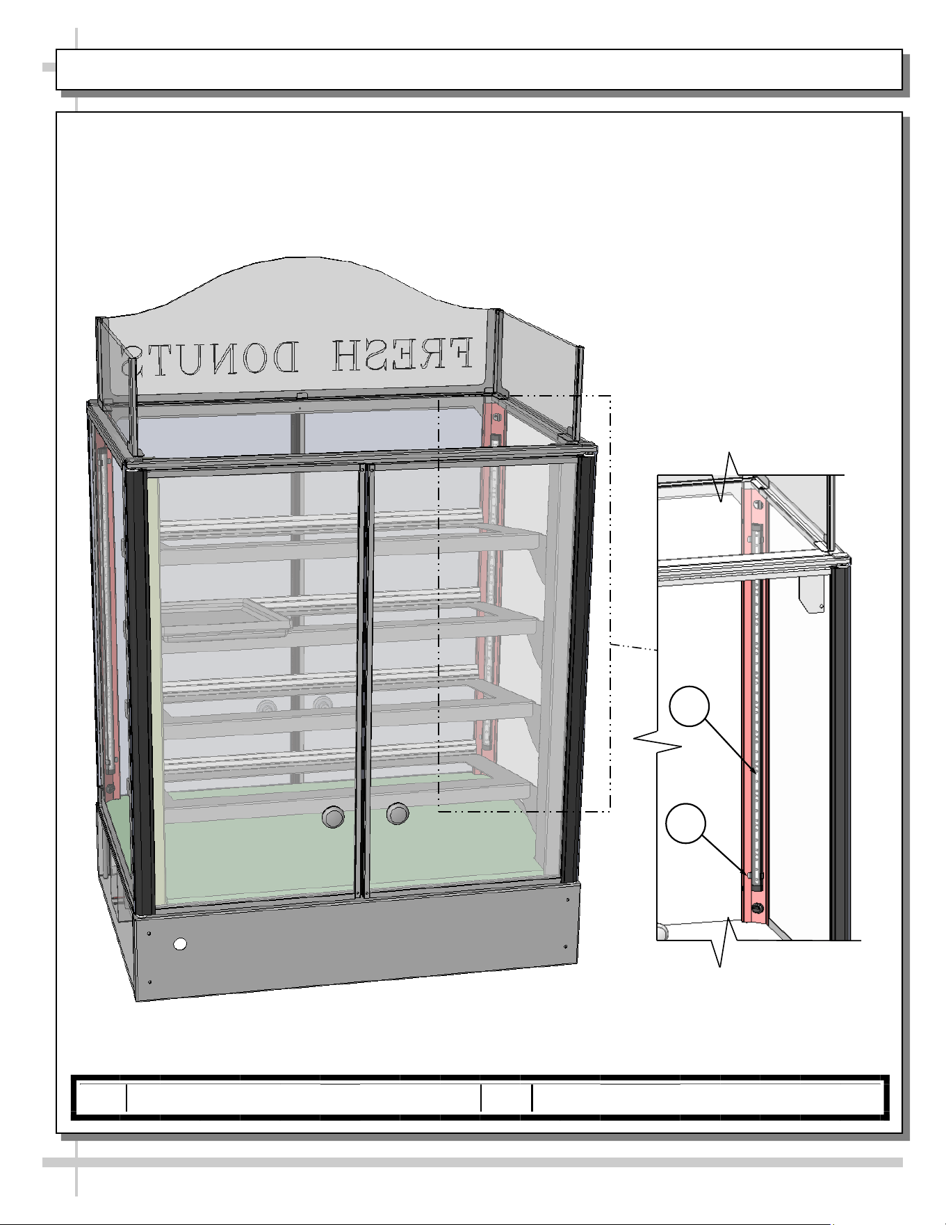
ILLUSTRATED PARTS BREAKDOWN, CONT’D
15
14
17
18
16
Note: Depending Upon Features And
Options Chosen, Illustration Shown May
Not Exactly Reflect Your Particular Case.
13 Panel_Back_Lower_Base 15 Knob_Door_Rear_Right 17 Door_Glass_Rear_Left
14 Door_Glass_Rear_Right 16 Knob_Door_Rear_Left 18 Cord_Power
13
12
ILLUSTRATED PARTS BREAKDOWN, CONT’D
22
24
23
21
19
20
Note: Depending Upon Features And
Options Chosen, Illustration Shown May
Not Exactly Reflect Your Particular Case.
19 Channel_Price (Typ.) 21 Switch_Light 23 Magnet_Tissue Dispenser (Typ.)
20 Shelf (Typ.) 22 Driver_VCD 24 Dispenser_Tissue
13
ILLUSTRATED PARTS BREAKDOWN, CONT’D
13 13
Light Assembly
26
25
25 Light_LED (Typ.) 26 Clip_Retaining_LED (Typ.)
14
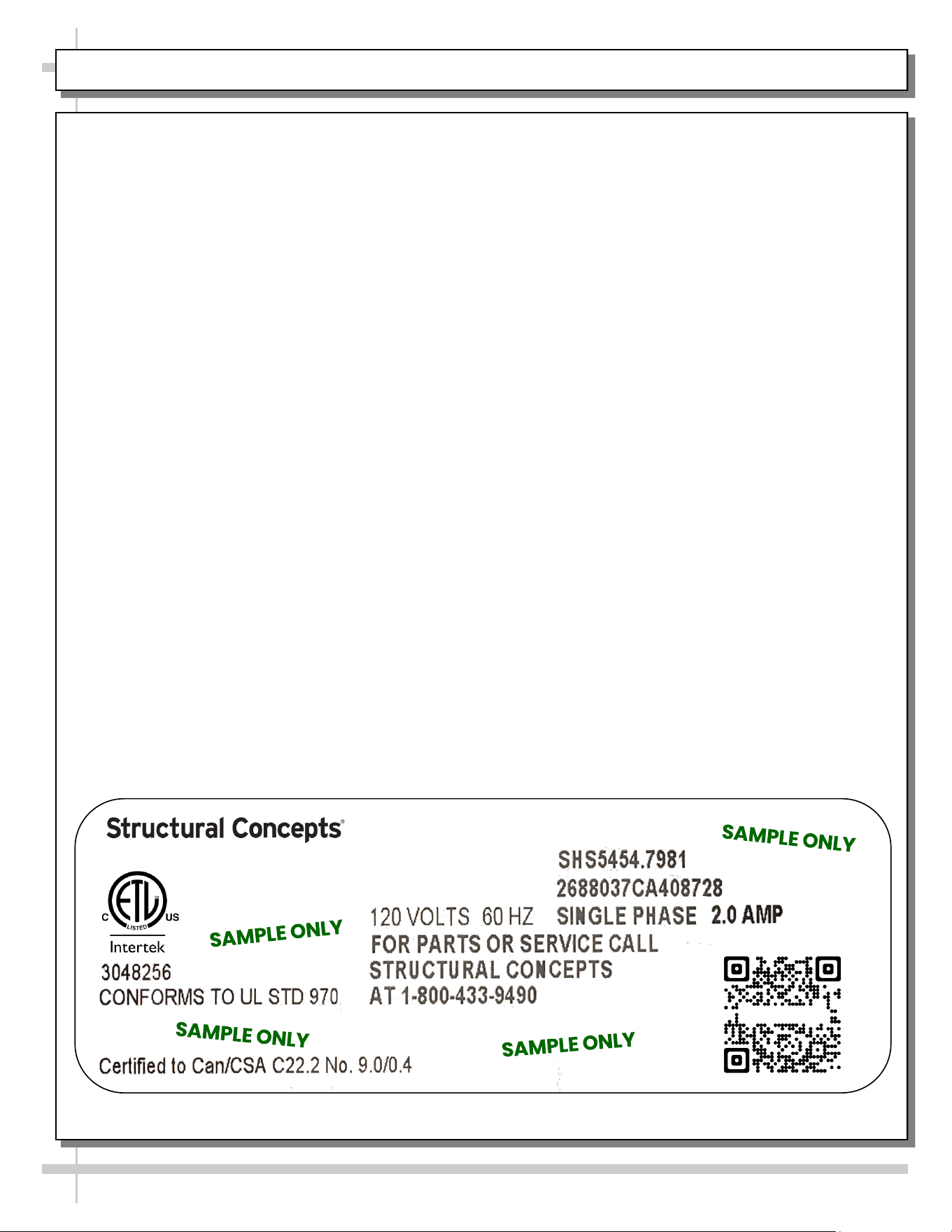
SERIAL LABEL LOCATION & INFO LISTED / TECH INFO & SERVICE - AMBIENT/HEATED CASES ONLY
Serial Label Location & Information Listed /
Technical Information & Service
• Serial labels are affixed at a wide range of places
(on the header, at case rear, behind panels or
toe-kicks, on electrical boxes, etc.).
• Serial labels contain electrical information as well
as regulatory standards to which the case
conforms.
• Sample serial label is shown. A variety of models is
displayed on serial label for illustration purposes only.
Your case’s serial label will reflect only one model.
• For additional technical information and service, see
the TECHNICAL SERVICE page in this manual for
instructions on contacting Structural Concepts’
Technical Service Department.
--- Sample Serial Label For Ambient/Heated Cases ---
888 E. Porter Rd - Muskegon, MI 49441
Sample QR Code
SCAN FOR PRODUCT LITERATURE
Fusion
15
STRUCTURAL CONCEPTS TECHNICAL SERVICE CONTACT INFORMATION & LIMITED WARRANTY
TECH SERVICE/WARRANTY CONTACT INFO:
1 (800) 433-9490 / EXTENSION 1
DAYS/HOURS AVAILABLE:
MONDAY - FRIDAY (CLOSED HOLIDAYS)
8:00 AM to 8:00 PM EST
YOU MUST HAVE THE FOLLOWING INFO AVAILABLE
BEFORE CONTACTING STRUCTURAL CONCEPTS:
SERIAL NO. / MODEL NO. / STORE NO. / STORE
ADDRESS / DETAILS (PHOTOS, LEAK LOCATIONS,
DAMAGE, STORE’S AMBIENT CONDITIONS, ETC.)
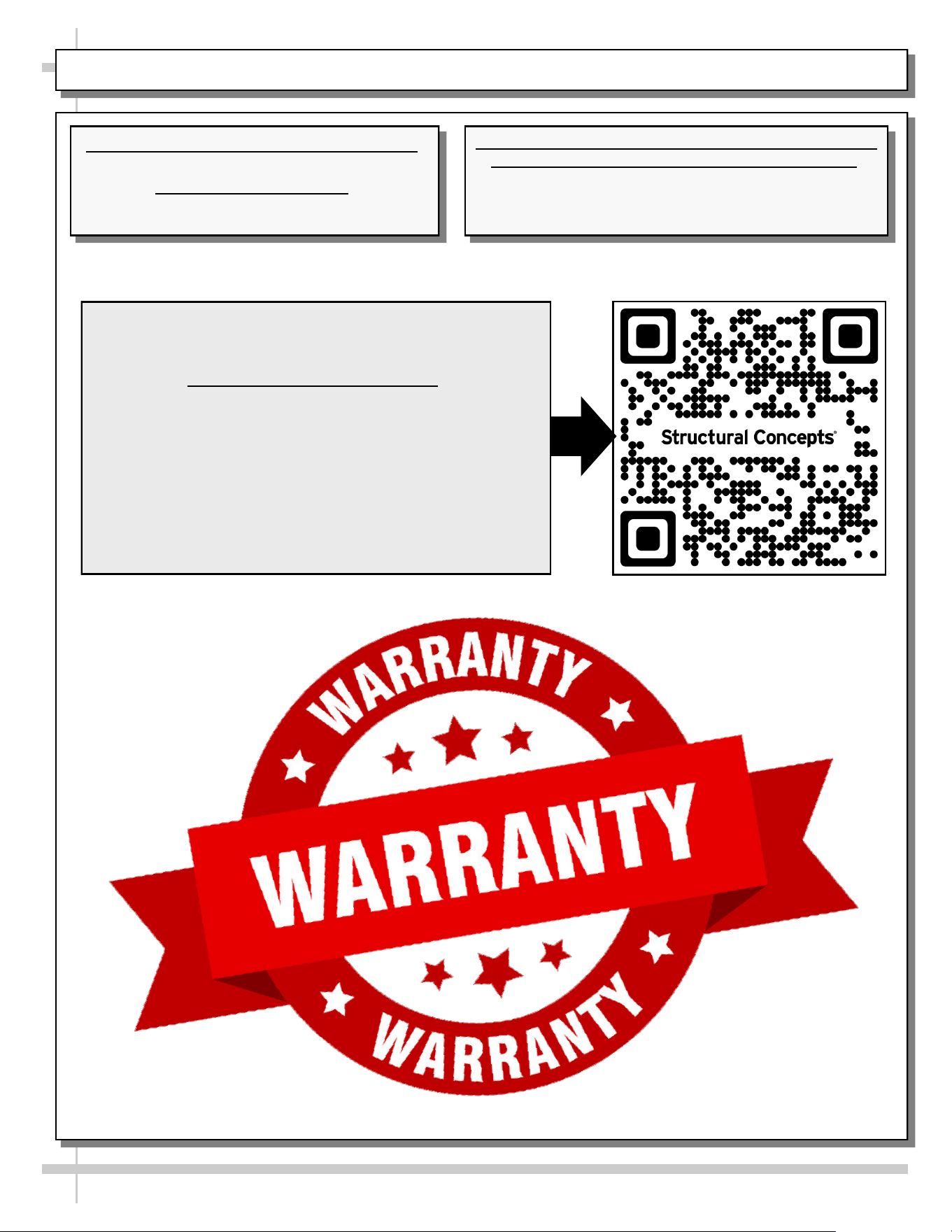
To Access The Limited Warranty To Your
Case, Follow These Instructions:
> If Viewing This Document on Smart Phone,
Tablet or Computer, Select/Click On The QR
Code at Right.
> If Viewing This Document In Print (Hard
Copy), Scan The QR Code at Right With Your
Smart Phone or Tablet.
16
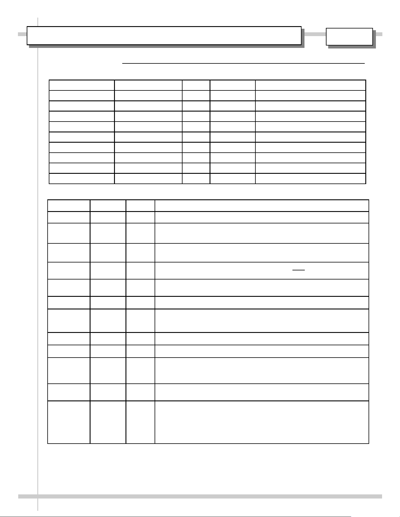
USER MANUAL / APPROVALS, ROUTINGS, REVISIONS
REV LEVEL DATE BY REVISION(S)
A 08.28.2003 KStroup RELEASE FOR PRODUCTION
B 03.30.2005 BRO Impulse Model had been Velo. Removed model CSCI3223 from this Oper.
Manual. CSF4231 (floor model) now transferred to Oper. Manual 99696.
C 8.23.2007 RMW Replaced Tech Info Sheet with Serial Label Data Sheet. Removed wiring
diagram and added new logos.
D 4.22.2008 BRO Added LED lighting as it relates to CSC3223.4254. Note: Billwork reflects this
CDR being added to this manual. However, Q4254 not shown on cover sheet.
E 6.29.2010 BRO Added model CDR4817 to manual. Added optional Ryobi door mechanism;
showed optional dividers to front storage area.
F 6.19.2012 BRO Revised Warranty Sheet, Overview/Warnings Sheet and Matting, etc.
G 6.20.2012 BRO Listed [on Cover] P/N 20-16813 as Corresponding Field Service Parts List.
Dropped Refrigeration Data from Serial Label Sheet. Combined Troubleshoot-
ing and Cleaning Schedule pages.
H 2.11.2013 BRO GFCI now mandated.
I 8.27.2019 CTG/BO Updated Warranty Sheet, Added LED Sheet, Added P65 Warning
J 6/7/2022 BRO
REVISION DESCRIPTION: REVISED MANUAL FOR QR CODE IMPLEMENTATION.
REVAMPED DOCUMENT DESCRIPTION (NOW, USER MANUAL). CHANGED FILE
NAME (P/N LISTED FIRST). REPLACED SCC LOGO (WITH NEW), SERIAL LABEL
AND WARRANTY SHEET.
K 6/19/2023 BRO Added “Fresh” tag line to logo. Swapped out Warranty Sheet for QR Code
segue to latest warranty sheet.
L 09/22/2023 BRO CHANGED TECHNICAL SERVICE HOURS TO 8AM TO 8PM. CHANGED
FAMILY PRODUCT NAME FROM FUSION TO IMPULSE. CHANGED COVER
SHEET MODEL FROM OLD LINE DRAWING TO 3D ISOMETRIC SOLID
WORKS MODEL REVISED THE FIELD SERVICE PARTS LIST TO REFLECT
THE LATEST MODEL’S (CSC3223) DESIGN. REMOVED REFERENCE TO A
SEPARATE FSPL (P/N 20-16813).
REVISIONS
ROUTED TO: DEPARTMENT INITIALS SIGNOFF DATE COMMENTS
LINDA KARR REG. COMPLIANCE
JASON PAQUETTE REFRIG. ENGINEERING
BILL KANGAS REFRIG. ENGINEERING
RUSS STONE PROD. ENGINEERING
CHRIS GORT TECHNICAL WRITER
BILL VANDERLINDE PROJ. MANAGEMENT
VERN DEBOER PROJ. MANAGEMENT
FRED VANDONKELAAR PROJ. MANAGEMENT
BERT OGBORN TECHNICAL WRITER BRO 09/22/2023
ROUTINGS / SIGNOFF
DATE DUE / COMMENTS:
99425