REV E DATE: 11/22/2022
USER MANUAL/21-05852_IMPULSE_USER MANUAL_CGSV(L)22_CGSV(L)30_AMBIENT_SVC_SELF-SVC_C-TOP CASE
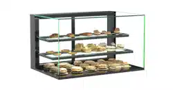
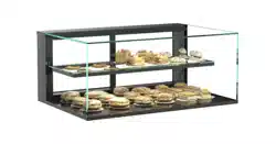
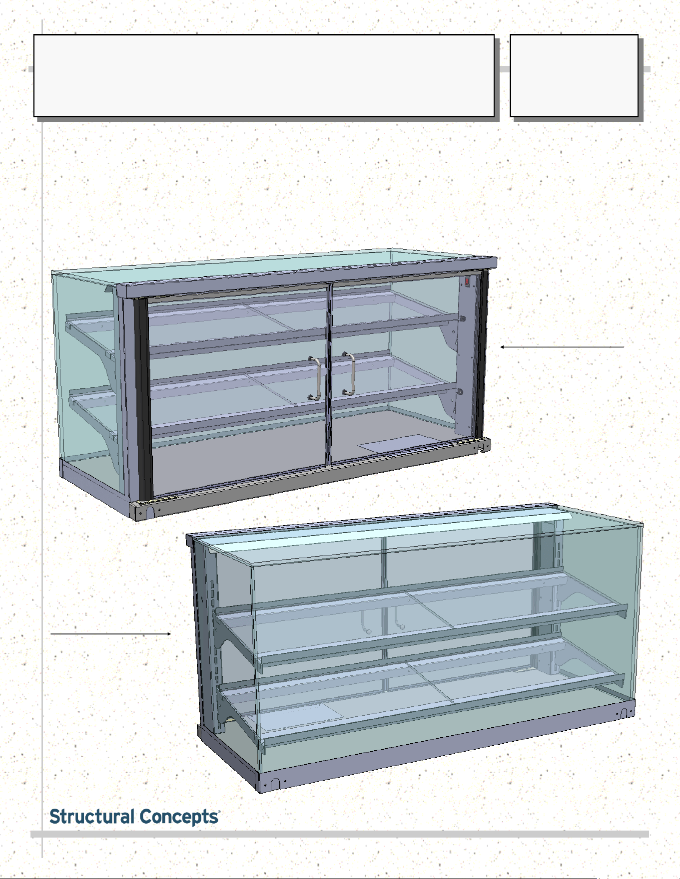
SELF-SERVICE / SERVICE COUNTERTOP AMBIENT DISPLAY UNITS
> UV-BONDED GLASS > HINGED DOORS WITH HANDLES
> PRODUCT IS ACCESSED VIA HINGED DOORS > LED DRIVER BOX IS AT CASE UNDERSIDE
> APPLICABLE TO THE FOLLOWING MODELS: CGSV3622, CGSV4522, CGSV4530,
CGSV6022, AND CGSV7222. MAY ALSO BE APPLICABLE TO MODELS NOT LISTED HEREIN.
Model CGSV4522
As Service Unit
Model CGSV4522
As Self-Service Unit
SCC P/N
21-05852
USER
MANUAL
IMPULSE
CAREFULLY FOLLOW THESE INSTRUCTIONS
Structural Concepts Corp. ∙ 888 E. Porter Rd ∙ Muskegon, MI 49441 Phone: 231.798.8888 Fax: 231.798.4960 ∙ www.structuralconcepts.com
2
TABLE OF CONTENTS
OVERVIEW / TYPE / COMPLIANCE / WARNINGS / PRECAUTIONS / WIRING / PLUGS .....…....…..
CASE AT SHIPMENT / BLOCK REMOVAL / SEPARATELY SHIPPED SHELVING COMPONENTS
AND THEIR PLACEMENT …………………………………………………………………………….
SELF-SERVICE MODE VS. SERVICE MODE VS. RANDOM SHELVING POSITIONING …………….
CASE STARTUP / LED LIGHT FIXTURE REPOSITIONING (SERVICE VS. SELF-SERVICE / LED
DRIVER) ……………………………………………………………………………........………………
LED STYLE LIGHT FIXTURES ………………………………………………………………………………..
HINGED DOORS / LED DRIVER BOX ACCESS …………………….……………………………………...
SERIAL LABEL LOCATION & INFORMATION LISTED / TECH INFO & SERVICE …………….….….
CLEANING SCHEDULE .……………..…………………………………...…………………….………….….
TROUBLESHOOTING …….………….………………………………………………………….….………….
SCC TECHNICAL SERVICE CONTACT INFORMATION / WARRANTY INFORMATION ..……........
3
4
5
6
7
8
9
10
11
12
3
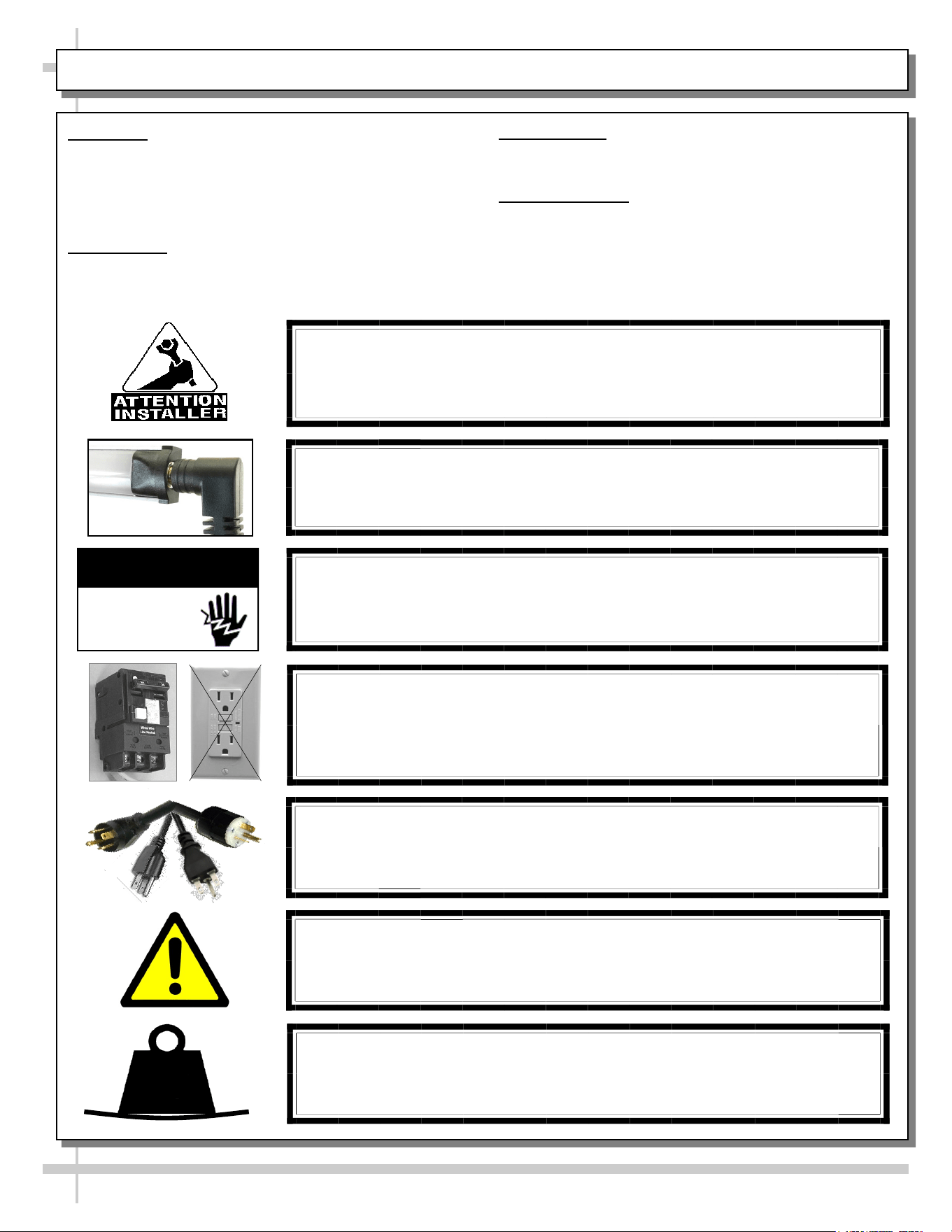
OVERVIEW
• These Structural Concepts cases should be installed and
operated according to these instructions to ensure proper
performance. Improper use will void warranty.
• This unit is designed to display of products in ambient
store conditions with a max. temperature of 80 °F (27 °C) .
COMPLIANCE
• Performance issues when in violation of applicable NEC,
federal, state or local electrical codes are not covered by
warranty. See below.
WARNING
Risk of electric shock.
Disconnect ALL ELECTRICAL SOURCES before servicing.
WARNING
ELECTRICAL
HAZARD
COMPLIANCE
This equipment MUST be installed in compliance with all applicable NEC,
federal, state and local electrical and plumbing codes.
PRECAUTIONS
• Following are important precautions to prevent damage
to unit or merchandise. Read carefully!
WIRING DIAGRAM
• Each case has its own wiring diagram folded and in its
own packet. It may be placed near ballast box, field
wiring box, raceway cover, or other related location.
CAUTION! POWER CORD AND PLUG MAINTENANCE
Risk of electric shock. If cord or plug becomes damaged,
replace only with cord and plug of same type.
CAUTION! GFCI BREAKER USE REQUIREMENT
If N.E.C. (National Electric Code) or your local code
requires GFCI (Ground Fault Circuit Interrupter) protection,
you MUST use a GFCI breaker in lieu of a GFCI receptacle.
OVERVIEW / COMPLIANCE / WARNINGS / PRECAUTIONS / WIRING DIAGRAM / CORDS & PLUGS
CAUTION! LAMP REPLACEMENT GUIDELINES
If LED lamps are used, they must be size, shape and overall design.
Any replacements must meet factory specifications.
WARNING: This product can expose you to chemicals, including
Urethane (Ethyl Carbamate), which are known to the state of
California to cause cancer and birth defects or other reproductive
harm. For more information go to P65Warnings.ca.gov.
CAUTION!
• To prevent sagging or breakage, do not exceed 5 LBS (2.3 KG) weight load
per top glass section (between vertical supports).
• To prevent scratching or marring, do not place ANY items on glass.
5
LBS
4
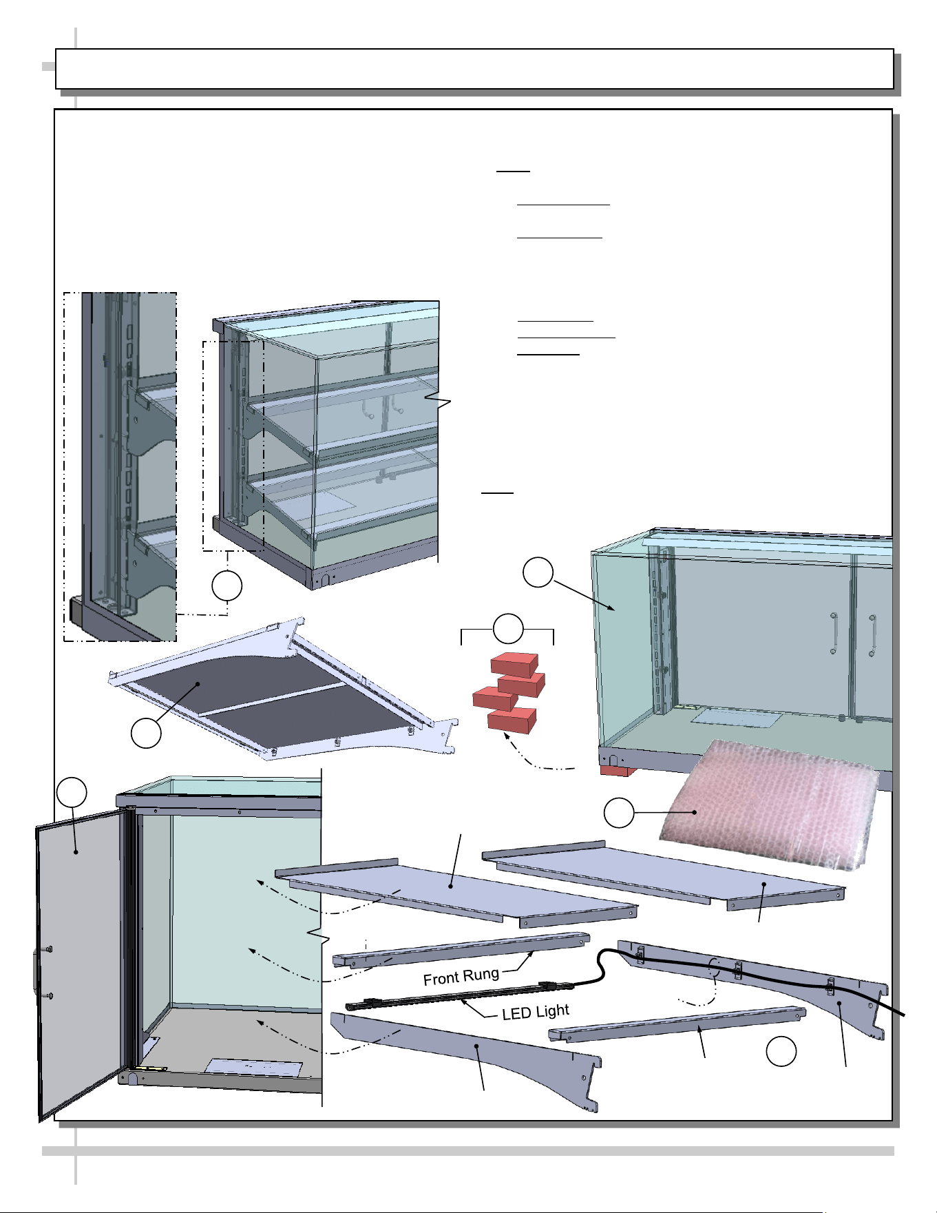
CASE AT SHIPMENT / BLOCK REMOVAL / SEPARATELY SHIPPED SHELVES & THEIR PLACEMENT
1
3
2
4. Open case’s hinged door. Follow steps A through E to
place shelving components into case ONE AT A TIME.
Note: Insert lowest shelf components first, followed
by top shelf components.
A. Side brackets: Insert into upright slots (following
bracket/slot pattern shown in view #7).
B. Bottom shelf: LED lighting is optional. If LED light is in
kit, attach under front rung. Attach front rung between
shelving brackets. Insert LED plug into light. Route wires into
wire clips that are attached to side bracket. Connect the
opposite-end LED plug into upright connectors.
C. Rear rungs: Attach to shelving brackets.
D. Metal shelving: Attach atop shelving brackets.
E. Top shelf: LED lighting is standard. Follow items A-D
(above) shelving component attachment instructions.
5. View of case awaiting shelving components.
6. View of assembled shelf (for illustrative purposes only).
7. View of recommended slot spacing after shelving has
been properly inserted into case.
> After shelving has been properly placed in case (and
LED lights have been properly connected), turn lights on.
> Note: Service case shown. This process is also applicable
to self-service cases. See next page for slot spacing guide.
Follow These Instructions For Proper Case
Removal From Skid / Shipping Block Removal /
Shelving Component Access & Placement, Etc.
1. View of case at shipment (no shelves installed / skid
not shown).
2. Remove shipping blocks from case underside
(attached to skid with screws). Set case on counter.
3. Carefully remove separately shipped shelving from
its protective bubble wrap.
4
Side Bracket
Side
Bracket
Rear Rung
Metal Shelf
Metal Shelf
5
6
LED Wire
7
5
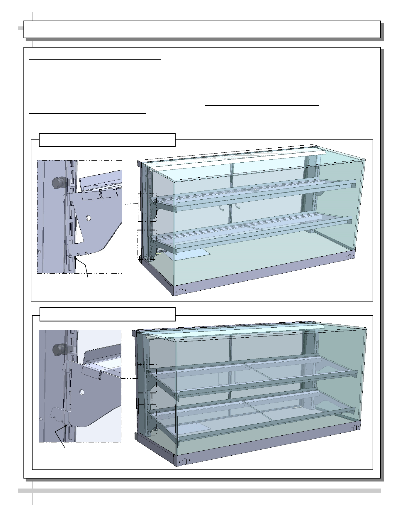
SELF-SERVICE MODE VS. SERVICE MODE VS. RANDOM SHELVING POSITIONING
1. Self-Service Mode Shelving Position
• Shelves may be positioned in the “up” position to
merchandise as a self-service case.
• Number of open slots above, between and below
shelving remains the same as unit in service mode.
• See illustration #1 below.
2. Service Mode Shelving Position
• Shelves may be positioned in the “down”
Shelving Brackets
Set At Third Notch
1. Merchandiser In Self-Service Mode
position to merchandise as a service case.
• Number of open slots above, between and below
shelving remains the same as unit in self-service
mode.
• See illustration #2 below.
3. Random Mode Shelving Position
• Shelves may be adjusted to second notch at will.
• Shelves may also be raised or lowered to desired
slot along uprights.
2. Merchandiser In Service Mode
Shelving Brackets
Set At First Notch
6
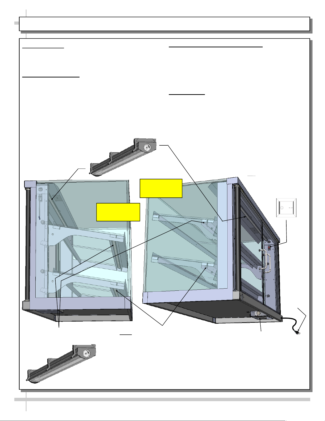
CASE STARTUP / LED LIGHT FIXTURE REPOSITIONING (SERVICE VS. SELF-SERVICE / LED DRIVER)
3. LED Light Fixture Repositioning
• Service cases have LED lights opposite uprights.
• Self-Service cases have LED lights positioned
near uprights.
• Important! You must reposition LED lights if
changing case from service to self service
(or vice versa). See below for illustrations.
4. LED Driver
• LED driver box is located at rear-underside of unit.
• See next page for access instructions.
ON OFF
1. Case Startup
• Case will be energized when plugged into outlet.
• Lights will turn on when rocker switch (located at
case upright) is turned on.
2. LED Light Fixtures
• LED lights are located at both header and shelving
of case (as shown below).
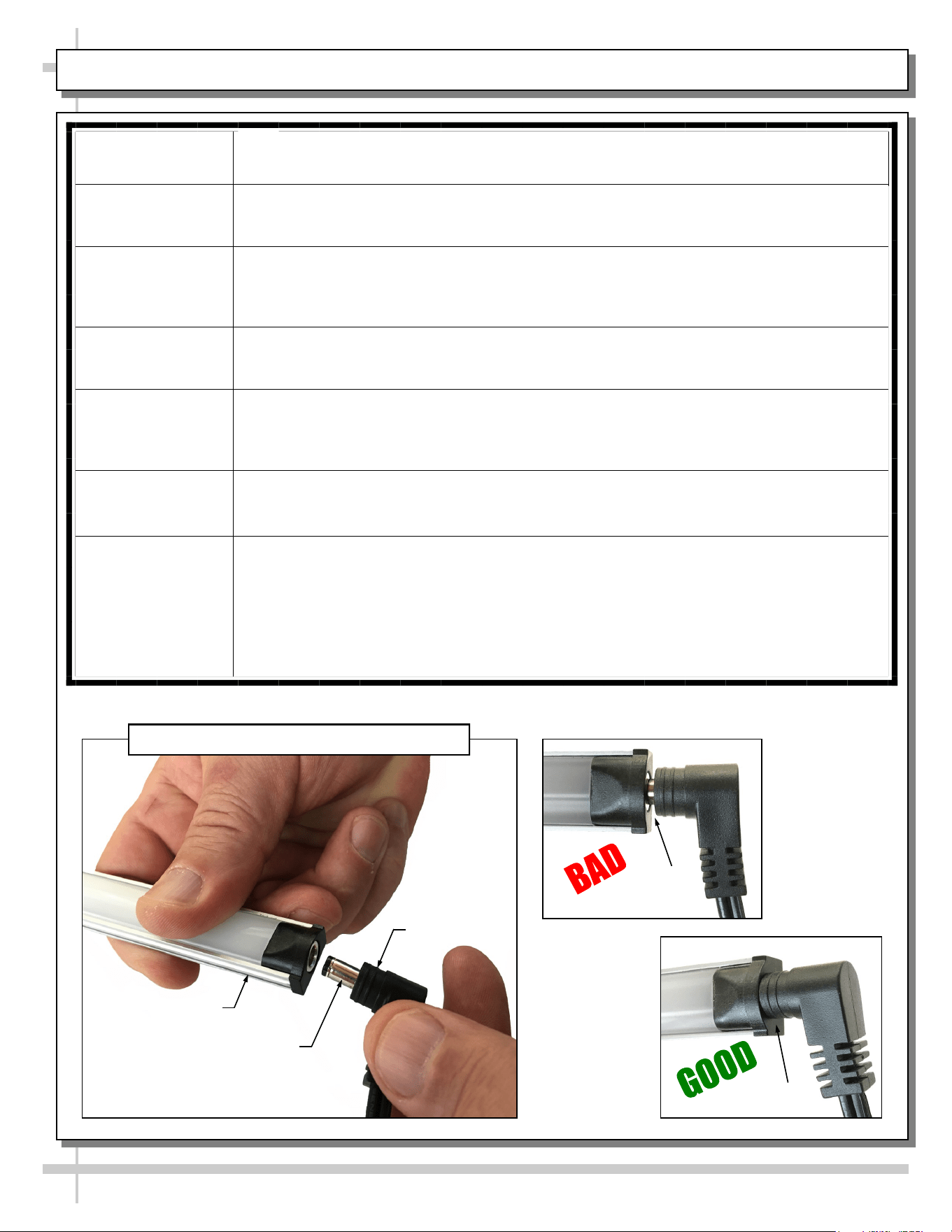
• Check that ALL of the light plugs are properly
connected to the LED light.
• Plug must be inserted ALL THE WAY into the
LED light orifice (with no gap) to work properly.
LED Driver
And Box
LED Lights
Rocker Switch
3-Prong
Plug
Note: Lower Shelf LED Light Is An
Optional “Upcharge” Item. It May Be
Ordered As An Aftermarket Piece With
A Harness And Installed In The Field.
Service Case
Shown
Self-Service
Case Shown
LED Light (Under Header) Typ.
LED Light
(Under Shelves) Typ.
7
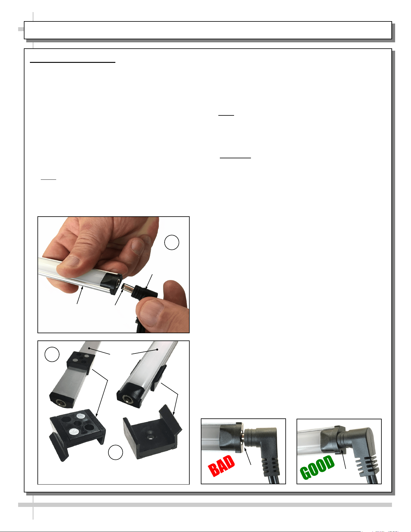
LED Style Light Fixtures
Removal of Faulty LED Lights:
• LED lights rarely require change-out.
• Contact Structural Concepts’ Technical Service
Department for replacement LED lights.
• Turn off LED light switch.
• To remove faulty LED light, follow these steps:
A. Disconnect plug from LED light.
B. Using both hands, grasp LED light assembly
(with its magnetic mounting clips). Pull
downward and off its shelf (or header).
C. Remove magnetic mounting clips from LED
light by pressing against flange part of clip
with thumb.
>> Note: Mounting clips MAY be riveted to shelf or
header. In such instances, simply remove LED light
from mounting clips by pressing against flange part
of clips with thumb.
LED STYLE LIGHT FIXTURES
Replacement of LED lights:
• Attach magnetic mounting clips onto LED light.
• Adjust magnetic mounting clips so they are equally
spaced on LED light.
• Reattach LED light assembly to its shelf/header.
• Position properly in shelf/header.
>> Note: If mounting clips are riveted to shelf (or
header), attach by placing LED in base of clip and
then snapping into clip at FLANGE SIDE.
• Press plug’s barrel-shaped insert all the way into
LED light.
• Important: If plug is not inserted ALL THE WAY IN
the LED light’s orifice, the light may not energize.
See “BAD” vs. “GOOD” insertion illustrations
below-right.
• Turn LED light switch back on.
No Gap
Gap
Magnetic
Mounting Clip View #2
LED
Lights
B
A
Plug
Barrel
Shaped
Insert
LED
Light
C
Magnetic
Mounting Clip View #2
8
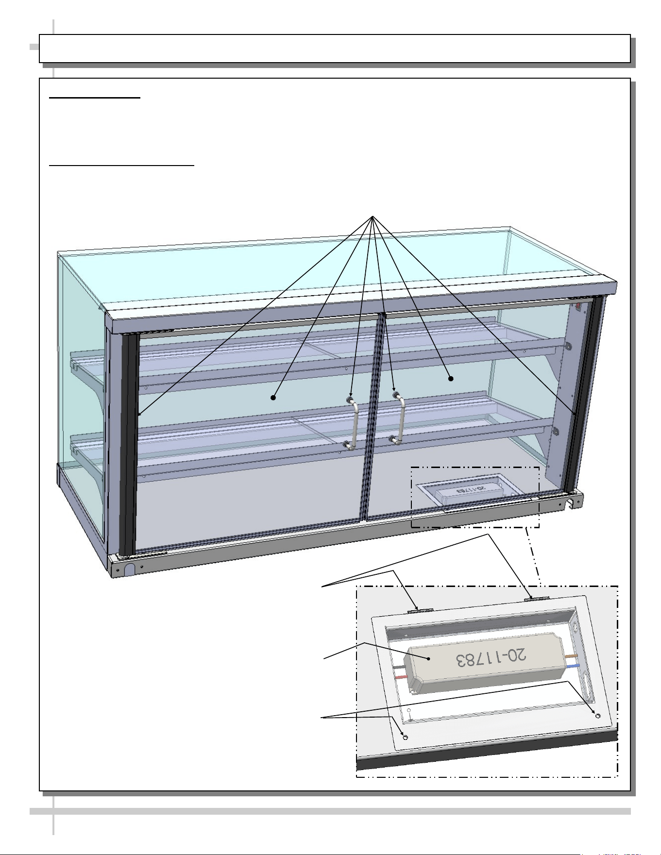
HINGED DOORS / LED DRIVER BOX ACCESS
1. Hinged Doors
• Hinged doors are illustrated below.
• Simply grasp handles and open doors to access
product.
2. LED Driver Access Box
• Caution! Only certified electricians should access
LED driver box!
• Access LED driver by opening hinged door.
• Remove LED driver box cover (via removal of
two screws).
• Remove cover tabs by lifting up and out of the
slots (that are in deck pan).
Led Driver Tabs (That
Slide In Deck Pan Slots)
Led Driver
LED Driver Box Cover
Retaining Screws
Hinged Doors, Hinges and Handles (Typ.)
9
CLEANING SCHEDULE
Cleaning Daily Weekly Task
Interior/Exterior X
Clean all glass surfaces with a household or commercial glass
cleaner and a soft cloth.
X
Clean the deck pan and shelving with damp cloth. For stubborn
stains or hardened residue, use hot, soapy water and soft-bristled
brush. Caution! Do not use brushes or pads with metal bris-
tles or coils to clean this unit as they will scratch and mar sur-
faces.
X
Stainless Steel Surfaces:
• Wash with a solution of hand dishwashing liquid detergent and
water; or a solution of baking soda and water. Rinse and polish
dry with paper towel or soft cloth.
• Never use scouring powders or steel wool as they will scratch
stainless steel.
• Brighten by polishing with a cloth dipped in vinegar or in
ammonia; sprinkle baking soda on sponge and rub gently; rinse.
Polish dry with paper towel.
• Remove streaks or heat stains from stainless steel by rubbing
with club soda.
10
TROUBLESHOOTING
System is not
Operating
Confirm the utility power is on (authorized personnel only).
Check the circuit breaker box for tripped circuits (authorized personnel only).
Case Lights Not
Working
Check that light switch is in the ON position.
• See CASE STARTUP / LED LIGHT REMOVAL & REPLACEMENT / LED
DRIVER BOX section in manual for switch location (regardless of case design).
If case is not hard-wired, check that power cord is properly connected to wall outlet.
Check that ALL of the light plugs are properly connected to the LED light.
• Plug must be inserted ALL THE WAY into the LED light orifice (with no gap).
• See illustrations below.
Power may not be reaching the case.
• Contact store management to have trained service provider perform
troubleshooting.
If case light still do not come on, it may need to be replaced.
• Contact Structural Concepts’ Technical Service Department for replacement
light (see TECHNICAL SERVICE section of this manual for contact
information).
• To replace, disconnect plug from existing LED light. Disconnect LED light from
its brackets. Replace with new LED light. Insert plug ALL THE WAY into LED
light orifice.
--- “Barrel-Shaped” LED Plug & Light Fixture ---
LED Light
Plug
LED’s Barrel
Shaped Insert
No Gap
Gap
11
SERIAL LABEL LOCATION & INFO LISTED / TECH INFO & SERVICE - AMBIENT/HEATED CASES ONLY
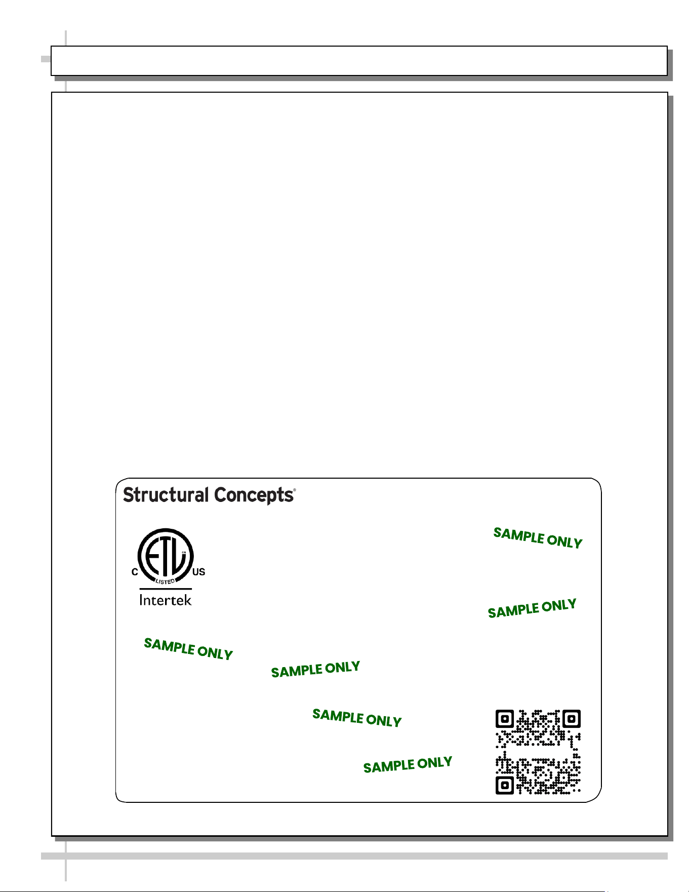
--- Sample Serial Label For Ambient/Heated Cases ---
MODEL NRS3648RXV-SAMPLE
SERIAL NO. 12345X30DZ098765
888 E. Porter Rd - Muskegon, MI 49441
3048256
Conforms to UL Std. 65
CERTIFIED TO CAN/CSA
STD C22.2 NO 120
120 VOLTS 60HZ
FOR PARTS OR SERVICE CALL
STRUCTURAL CONCEPTS
AT 1-800-433-9489
SINGLE PHASE 1.84 AMPS
Serial Label Location & Information Listed /
Technical Information & Service
• Serial labels are affixed at a wide range of places
(on the header, at case rear, behind panels or
toe-kicks, on electrical boxes, etc.).
• Serial labels contain electrical information as well
as regulatory standards to which the case
conforms.
• Sample serial label shown below.
• For additional technical information and service, see
the TECHNICAL SERVICE page in this manual for
instructions on contacting Structural Concepts’
Technical Service Department.
Sample QR Code
SCAN FOR PRODUCT LITERATURE
Reveal
Harmony
Fusion
Impulse
Addenda
Blend
Grocerant
Oasis
STRUCTURAL CONCEPTS TECHNICAL SERVICE CONTACT INFORMATION & LIMITED WARRANTY
12
TECH SERVICE/WARRANTY CONTACT INFO:
1 (800) 433-9490 / EXTENSION 1
DAYS/HOURS AVAILABLE:
MONDAY - FRIDAY (CLOSED HOLIDAYS)
8:00 a.m. TO 5:00 p.m. EST
YOU MUST HAVE THE FOLLOWING INFO AVAILABLE
BEFORE CONTACTING STRUCTURAL CONCEPTS:
SERIAL NO. / MODEL NO. / STORE NO. / STORE
ADDRESS / DETAILS (PHOTOS, LEAK LOCATIONS,
DAMAGE, STORE’S AMBIENT CONDITIONS, ETC.)
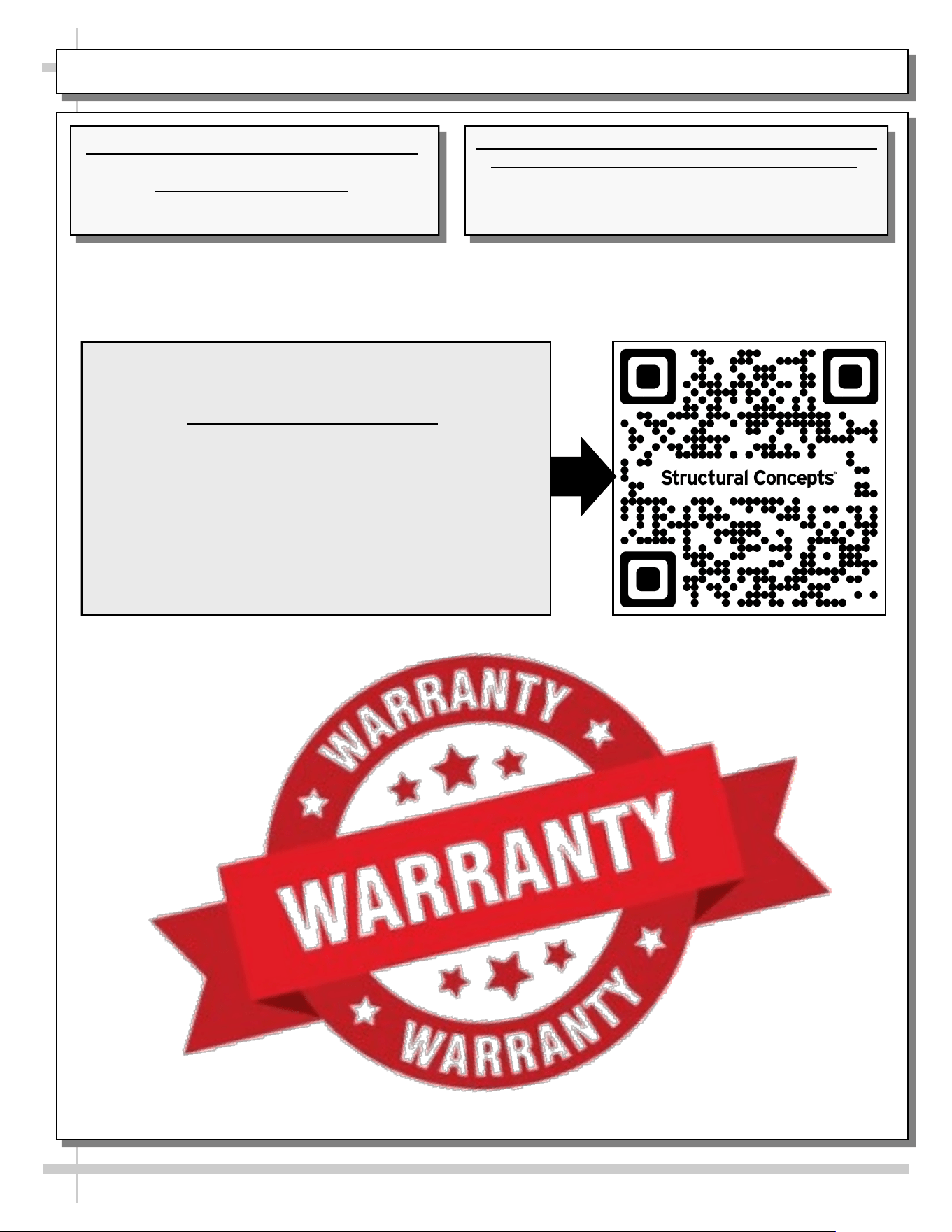
To Access The Limited Warranty To Your
Case, Follow These Instructions:
> If Viewing This Document on Smart Phone,
Tablet or Computer, Select/Click On The QR
Code at Right.
> If Viewing This Document In Print (Hard
Copy), Scan The QR Code at Right With Your
Smart Phone or Tablet.