BG-Commander
Universal Advanced Serial and IP PTZ Joystick Controller
with POE (IP/RS-232/422/485)
User Manual

BZBGEAR BG-Commander PRODUCT MANUAL
Address: 830 National Drive #140, Sacramento, CA 95834, USA · Tel: +1(888)499-9906 · Email: support@bzbgear.com 2

BZBGEAR BG-Commander PRODUCT MANUAL
TABLE OF CONTENTS
Statement 4
Safety Precaution 4
Introduction 5
Features 5
Packing List 5
Specifications 6
Device Interface 6
Application Diagrams 7
Button Descriptions 10
Preset Controls 12
Joystick Controls 12
Selecting Cameras 13
Device Menu Descriptions 13
Add a Network Device 14
Add an Analog Device 14
Device List 15
Network Configuration 16
Homepage Connection and Login 18
Device Management 19
Network Settings 20
System Upgrade 21
Reset 22
Restart 22
Import Configuration 23
Export Configuration 23
Account 24
Version 24
Troubleshooting 25
Tech Support 26
Limited Product Warranty Terms 26
Mission Statement 26
Copyright 26
Address: 830 National Drive #140, Sacramento, CA 95834, USA · Tel: +1(888)499-9906 · Email: support@bzbgear.com 3

BZBGEAR BG-Commander PRODUCT MANUAL
Statement
Please read these instructions carefully before connecting, operating, or configuring this
product. Please save this manual for future reference.
Safety Precaution
● To prevent damaging this product, avoid heavy pressure, strong vibration, or immersion
during transportation, storage, and installation.
● The housing of this product is made of organic materials. Do not expose to any liquid,
gas, or solids which may corrode the shell.
● Do not expose the product to rain or moisture.
● Do not drop the controller.
● Clean only with a soft dry microfiber cloth.
● To prevent the risk of electric shock, do not open the case. Installation and maintenance
should only be carried out by qualified technicians.
● Do not use the product beyond the specified temperature, humidity, or power supply
specifications.
● This product does not contain parts that can be maintained or repaired by users.
Damage caused by dismantling the product without authorization from BZBGEAR is not
covered under the warranty policy.
● Installation and use of this product must strictly comply with local electrical safety
standards.
Address: 830 National Drive #140, Sacramento, CA 95834, USA · Tel: +1(888)499-9906 · Email: support@bzbgear.com 4

BZBGEAR BG-Commander PRODUCT MANUAL
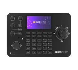
Introduction
The BG-Commander PTZ joystick controller delivers precise control for both IP and serial
PTZ cameras. With high-quality backlit buttons, the BG-Commander offers a pleasing user
experience - even in low-light conditions. The solid metal chassis provides a durable, stable
platform, and is designed to stand up to years of heavy use, regardless of the setting. This
controller is a great choice for live events, houses of worship, and broadcasting scenarios.
Features
● IP and analog control modes
● VISCA over IP, ONVIF, Pelco-P/D, and VISCA protocols
● Variable speeds for all control axes
● Zoom can be controlled by twisting the control handle or the dedicated zoom knob
● Integrated browser interface for quick setup
● Power over Ethernet (PoE) support
● Sturdy metal chassis
Packing List
● 1x BG-Commander
● 1x Power Supply
● 1x User Manual
Address: 830 National Drive #140, Sacramento, CA 95834, USA · Tel: +1(888)499-9906 · Email: support@bzbgear.com 5
BZBGEAR BG-Commander PRODUCT MANUAL
Specifications
Parameters / Model
BG-Commander
Chip
His3536DV100
System
Linux
Protocol
VISCA, ONVIF, PELCO-P, PELCO-D,VISCA OVER IP
Output
RS422, RS232, RJ45
Beep
On/off
Power consumption
≤5W
Power
DC12V-2A
Work temperature
14°F~131°F / -10°C ~55°C
Work humidity
20%~80% frostless
Storage temperature
14°F~140°F / -10°C ~60°C
Storage humidity
0~90% frostless
Packing size
13.4 x 10.6 x 5.5in [340 x 268 x 140mm]
Weight
7 lbs [3.18kg] / set
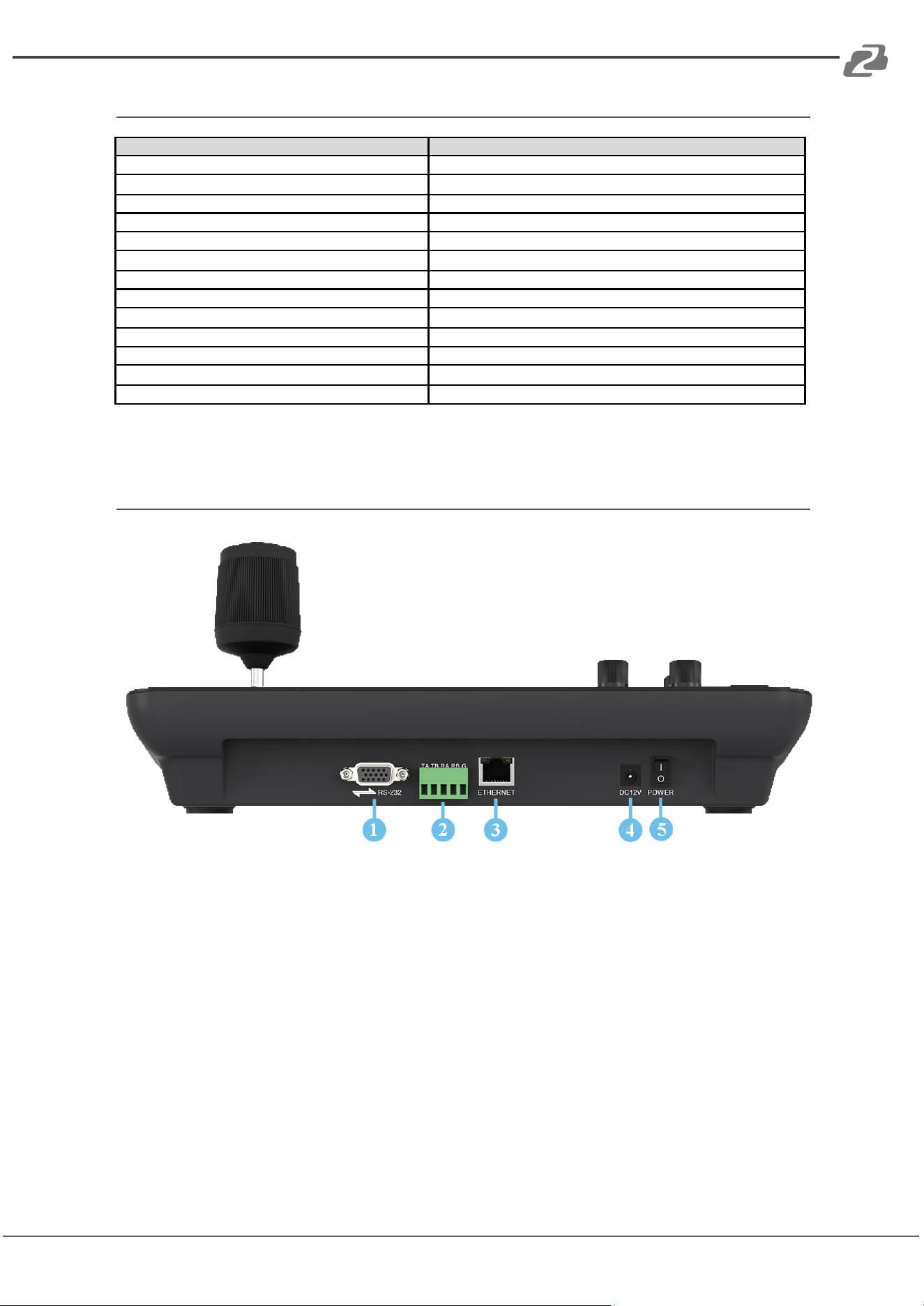
Device Interface
1. RS232, Supports Visca, Pelco-P/D
2. RS422/485, Supports Visca, Pelco-P/D
3. LAN Network Connection
4. Standard 5.5/2.1 power port, DC 12V2A±10%
5. Power switch on/off
Address: 830 National Drive #140, Sacramento, CA 95834, USA · Tel: +1(888)499-9906 · Email: support@bzbgear.com 6
BZBGEAR BG-Commander PRODUCT MANUAL
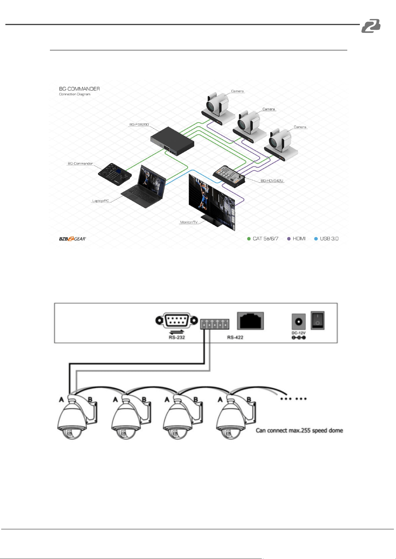
Application Diagrams
1. Network connection
Camera and keyboard need to be connected to the LAN.
2. RS485 connection diagram
Control output:
The RS485+ of the camera is connected to the Ta of the controller, and the RS485- of the
camera is connected to the Tb of the controller.
Address: 830 National Drive #140, Sacramento, CA 95834, USA · Tel: +1(888)499-9906 · Email: support@bzbgear.com 7
BZBGEAR BG-Commander PRODUCT MANUAL
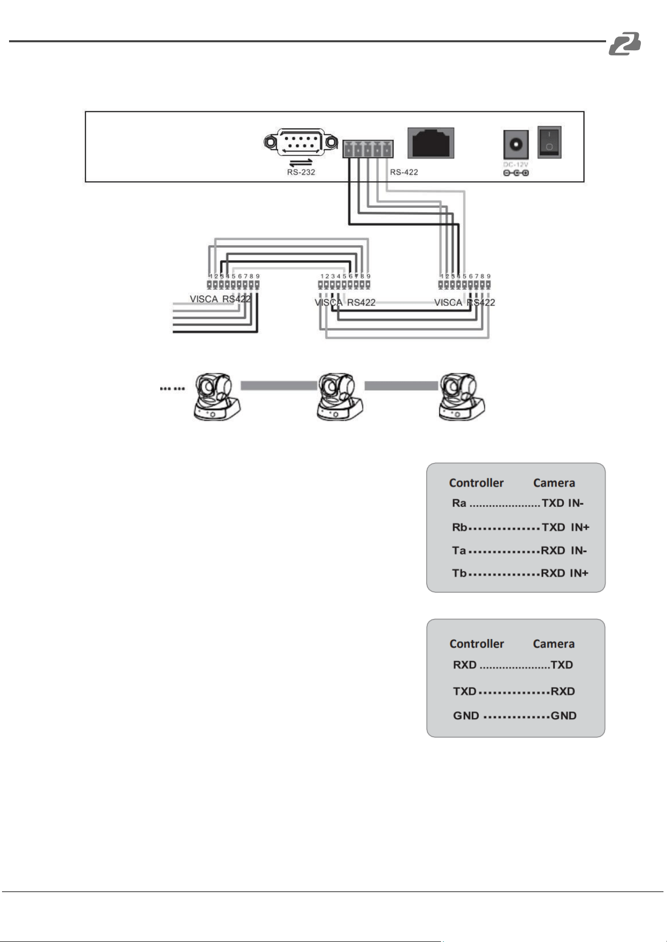
3. RS 422 connection diagram
7 cameras max
When using RS422 bus connection mode, the third pin (Ra)
of the controller is connected to the TXD IN- of the camera,
the fourth pin (Rb) of the controller is connected to the
TXD IN+ of the camera, the first pin (Ta) of the controller is
connected to the RXD IN- of the camera, and the second
pin (Tb) of the controller is connected to the RXD IN+
Using RS232 connection mode, the first pin (RXD) of the
controller (10 Pin terminal) is connected to the camera input
interface TXD, the second pin (TXD) of the controller is
connected to the camera RXD, and the third pin of the
controller is connected to the camera GND (you can also use
the standard RS232 DB9 interface of the controller to
connect the camera.
Address: 830 National Drive #140, Sacramento, CA 95834, USA · Tel: +1(888)499-9906 · Email: support@bzbgear.com 8
BZBGEAR BG-Commander PRODUCT MANUAL
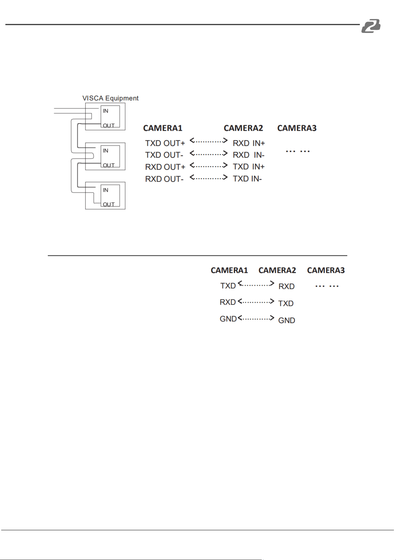
4. Connection between cameras
Using RS422 bus cascade connection mode, the output of camera 1 is connected to the
input of camera 2, the output of camera 2 is connected to the input of camera 3, and so on.
As below:
RS232 cascade connection
The output of camera 1 is connected to the
input of camera 2, the output of camera 2 is
connected to the input of camera 3, and so on.
Address: 830 National Drive #140, Sacramento, CA 95834, USA · Tel: +1(888)499-9906 · Email: support@bzbgear.com 9
BZBGEAR BG-Commander PRODUCT MANUAL
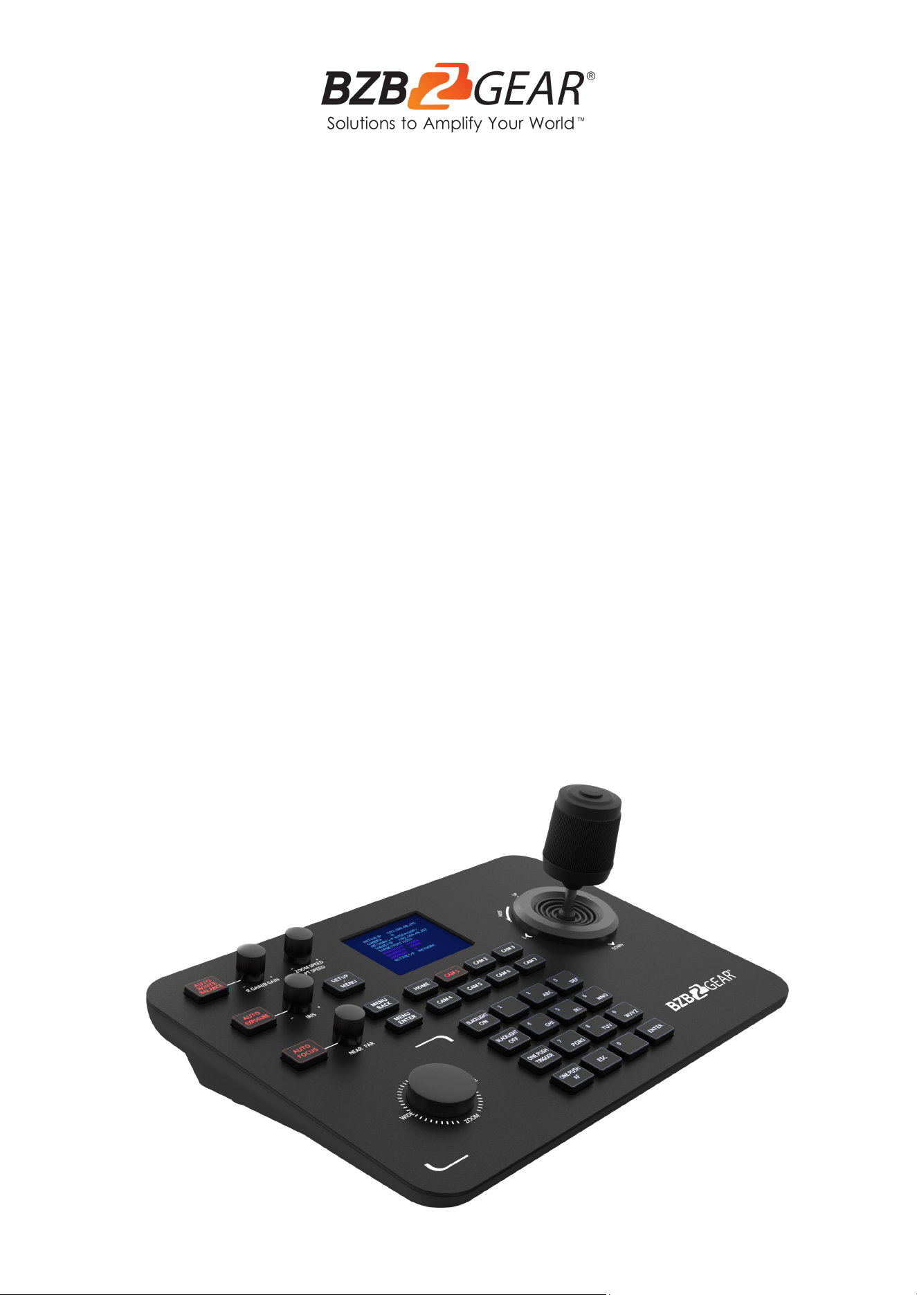
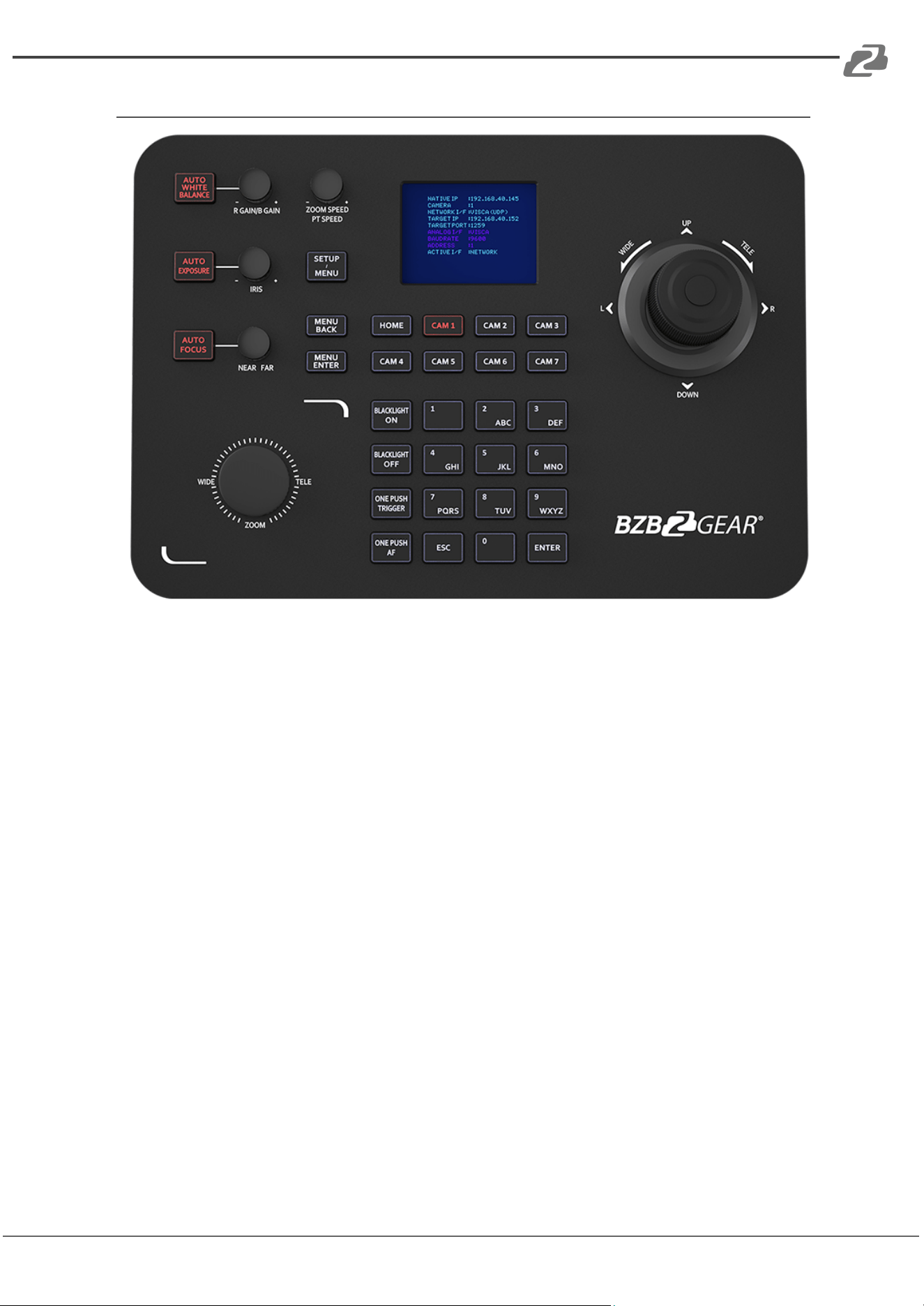
Button Descriptions
● [AUTO WHITE BALANCE]: When the button is illuminated red auto white balance is
active.
● [AUTO EXPOSURE]: When the button is illuminated red auto exposure mode is
active.
● [AUTO FOCUS]: When the button is illuminated red auto focus is active.
● [CAM 1 - 7]: When the button is illuminated red the selected camera can be
controlled.
● [MENU BACK]: While in the camera OSD press this button to go back one level.
● [MENU ENTER]: While in the camera OSD press to confirm/advance one level.
● [BACKLIGHT ON]: Tap once to enable Backlight Control (BLC)
○ BG-ADAMO ONLY: Double tap to turn on Green Tally Light.
○ BG-ADAMO ONLY: Press and hold to turn on Red Tally Light.
● [BACKLIGHT OFF]: Tap once to disable Backlight Control (BLC)
○ BG-ADAMO ONLY: Double tap to turn off Green Tally Light.
○ BG-ADAMO ONLY: Press and hold to turn off Red Tally Light.
Address: 830 National Drive #140, Sacramento, CA 95834, USA · Tel: +1(888)499-9906 · Email: support@bzbgear.com 10

BZBGEAR BG-Commander PRODUCT MANUAL
● [ONE PUSH TRIGGER]: Press to trigger white balance.
○ BG-ADAMO ONLY: Press and hold to turn off auto tracking.
● [ONE PUSH AF]: Press to trigger auto focus.
○ BG-ADAMO ONLY: Press and hold to turn on auto tracking.
● [ESC]: Exit.
● [ENTER]: Confirm.
● [0-9] Number Keys: Used to set numeric values in the menu and control presets.
● ZOOM SPEED/PT SPEED Knob: Zoom/PTZ speed adjustment- Turn the knob right
to increase speed, left to decrease speed. Press the knob to switch the adjustment
type.
● IRIS Knob: Adjust Exposure Turn- the knob to the right to open iris, turn left to close
iris. Press [AUTO EXPOSURE] to enable/disable manual iris control.
● RGAIN/BGAIN Knob: Red/Blue gain- Turn the knob right to increase gain, left to
decrease gain. Press the knob to switch the gain type. Press [AUTO WHITE
BALANCE] to enable/disable manual color correction.
● NEAR/FAR Knob: Turn the knob right to adjust focus toward distant objects, turn
the knob left to adjust focus toward near objects. Press [AUTO FOCUS] to
enable/disable manual focus control.
● Joystick Rotation: Rotate joystick handle clockwise to zoom in, counterclockwise
to zoom out.
● Joystick Top Button: acts as secondary Enter/Confirm
● Zoom Knob: Rotate knob clockwise to zoom in (telephoto), rotate counterclockwise
to zoom out (wide angle)
● [SETUP/MENU]:
1. Tap to enter the setup menu.
2. Press and hold to activate the camera OSD menu.
Address: 830 National Drive #140, Sacramento, CA 95834, USA · Tel: +1(888)499-9906 · Email: support@bzbgear.com 11
BZBGEAR BG-Commander PRODUCT MANUAL
Preset Controls
The BG-Commander can support 255 preset positions should the camera be able to
support that many. To set preset and recall camera positions select the camera using the
[CAM 1-7] buttons and then follow the instructions below.
Quick Access Presets 0-9
● Move the camera to the desired position using the joystick and zoom.
● Press and hold [0-9] number key for 3 seconds, “Preset #” will appear on screen
and then disappear when the preset camera position is saved.
● To recall a preset 0-9, tap the [0-9] number key and the camera will move to the
preset position.
Standard Presets 0-254
● Press and hold the [Enter] key, the LCD screen will display “LONG PRESS TO SET
PRESET”, conitune holding until the screen says “SET PRESET:-”.
● Use the number keys [0-9] to enter the desired preset number.
● Press the [Enter] key to save, move the joystick left to delete a number, or [ESC] to
cancel.
● To recall a standard preset 0-254 tap the [Enter] key, the LCD screen will display
“GOTO PRESET:-”
● Enter the preset number you wish to recall and press the [Enter] key to have the
camera move to the preset position.
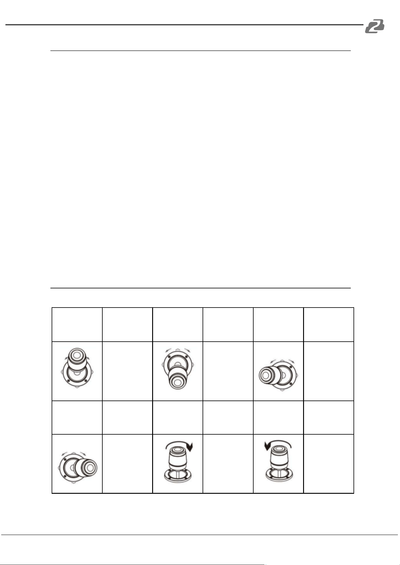
Joystick Controls
Operate
Output
control
Operate
Output
control
Operate
Output
control
Up
Down
Left
Operate
Output
control
Operate
Output
control
Operate
Output
control
Right
Zoom+
Zoom-
Address: 830 National Drive #140, Sacramento, CA 95834, USA · Tel: +1(888)499-9906 · Email: support@bzbgear.com 12
BZBGEAR BG-Commander PRODUCT MANUAL
Selecting Cameras
Controlling Cameras 1 - 7
To select a camera to control, press the corresponding [CAM #] button below the LCD
screen (such as [CAM 1]) and the button will illuminate red. The selected camera can
now be controlled.
Adding Cameras 8 - 256
To control cameras that do not have a [CAM #] button use the following sequence to
select the camera:
1) Press and hold the 0 key on the num pad for 3 seconds, the message “CAM ID:-”
will appear on the LCD Screen.
2) Type in the desired camera number using the num pad and press the [Enter] button.
3) The camera will now be able to be controlled and no [CAM #] button will be
illuminated.
4)
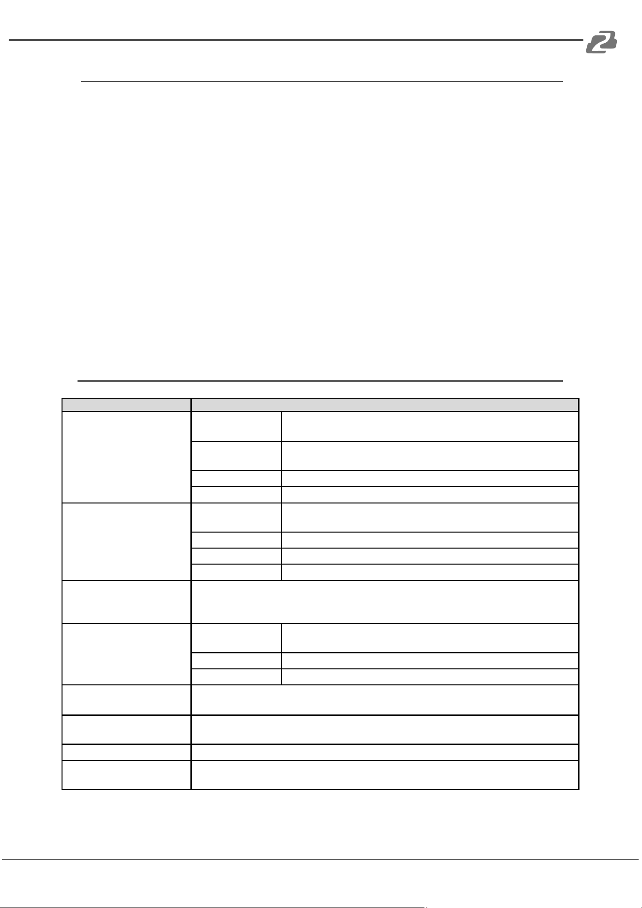
Device Menu Descriptions
Controller setting
Description
1. Add network device
Camera
The joystick ID of a camera can be 1-256; press [ENTER] to
save.
Protocol
Optional: VISCA (UPD), SONY VISCA (UDP), VISCA (TCP),
ONVIF, select the corresponding protocol of the camera.
IP address
Camera IP address.
Port
Input the camera port number.
2. Add analog device
Camera
The joystick ID of an analog camera can be 1-256, press
[ENTER] to save.
Protocol
Select the protocol corresponding to the camera.
Address code
Select the address code corresponding to the camera.
Baud rate
Select the baud rate corresponding to the camera.
3. Device list
The list of added cameras can be reviewed by moving the joystick up and
down. Press the button on the top of the joystick or press [ENTER] to
confirm.
4. Network properties
Network
properties
Switch through the options by moving the joystick left and
right, press [ENTER] to confirm.
Dynamic (DHCP)
Dynamic IP allocation based on switch settings.
Static
Manually enter IP address information for the controller.
5. Device Language:
EN/Chinese
Switch through the options by moving the joystick left and right, press [ENTER]
to confirm.
6. Key tone
Switch through the options by moving the joystick left and right, press
[ENTER]to confirm.
7. Reset
Double press [ENTER] to reset, press [ESC] to cancel.
8. System information
View the controller software, hardware, web version, gateway and subnet
mask.
Address: 830 National Drive #140, Sacramento, CA 95834, USA · Tel: +1(888)499-9906 · Email: support@bzbgear.com 13
BZBGEAR BG-Commander PRODUCT MANUAL
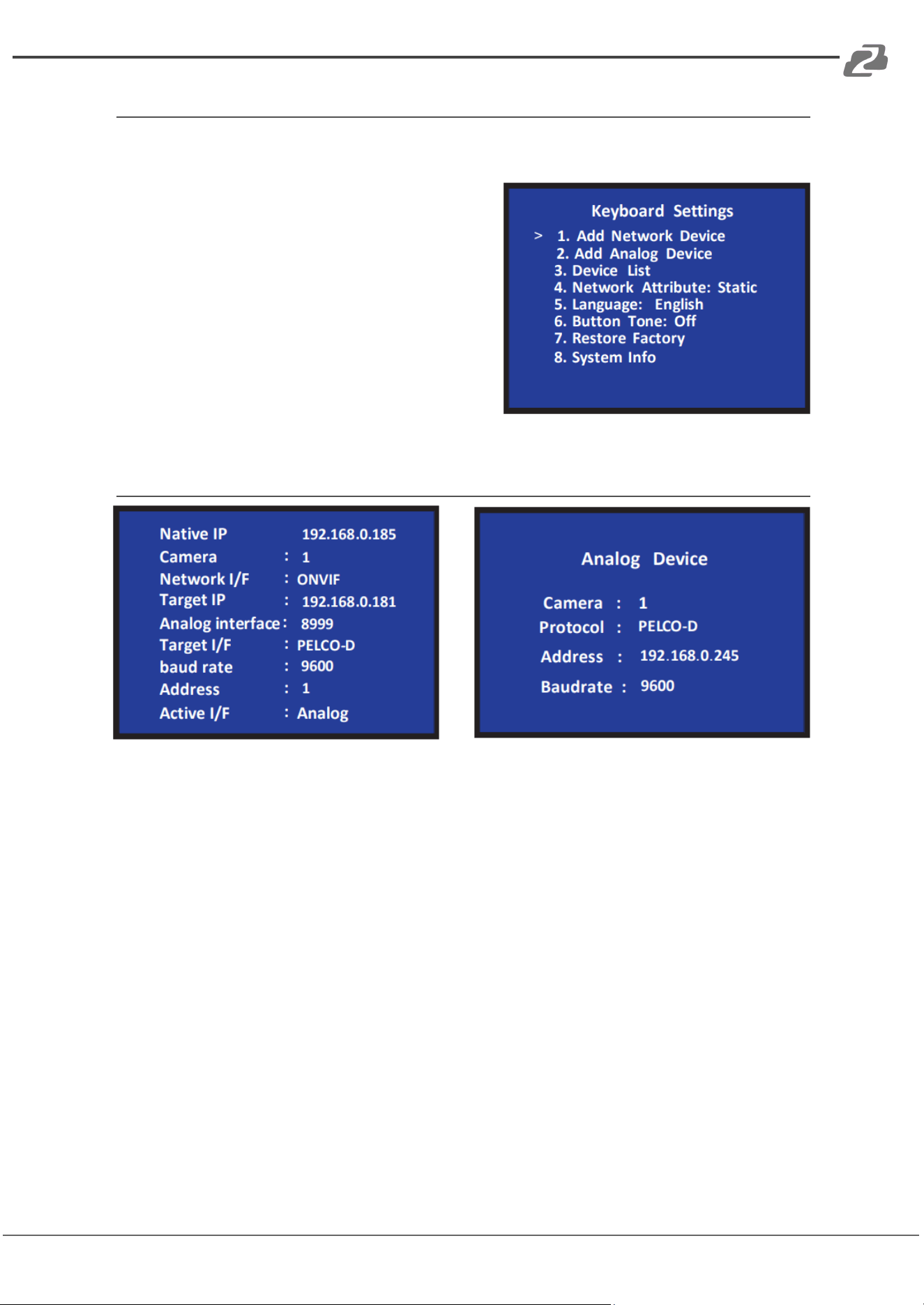
Add a Network Device
Use the controller to add a LAN devices as follows:
1. Press the [SETUP/MENU] key to enter
the main menu.
2. Select Add Network Device and press the
[ENTER] key.
3. Fill in the camera (1-7), protocol, IP
address, port, username and password (if
required), and press [ENTER] to save.
Add an Analog Device
1. Long press the button on top of the joystick handle to switch the analog mode.
2. Press [SETUP/MENU] button to enter the setting interface, select to add analog
device.
3. Enter the device adding interface, select the camera with 1-7 digital number, select
the corresponding analog protocol, select the address code corresponding to the
camera, select the baud rate, and press [ENTER] to confirm the addition.
Address: 830 National Drive #140, Sacramento, CA 95834, USA · Tel: +1(888)499-9906 · Email: support@bzbgear.com 14
BZBGEAR BG-Commander PRODUCT MANUAL
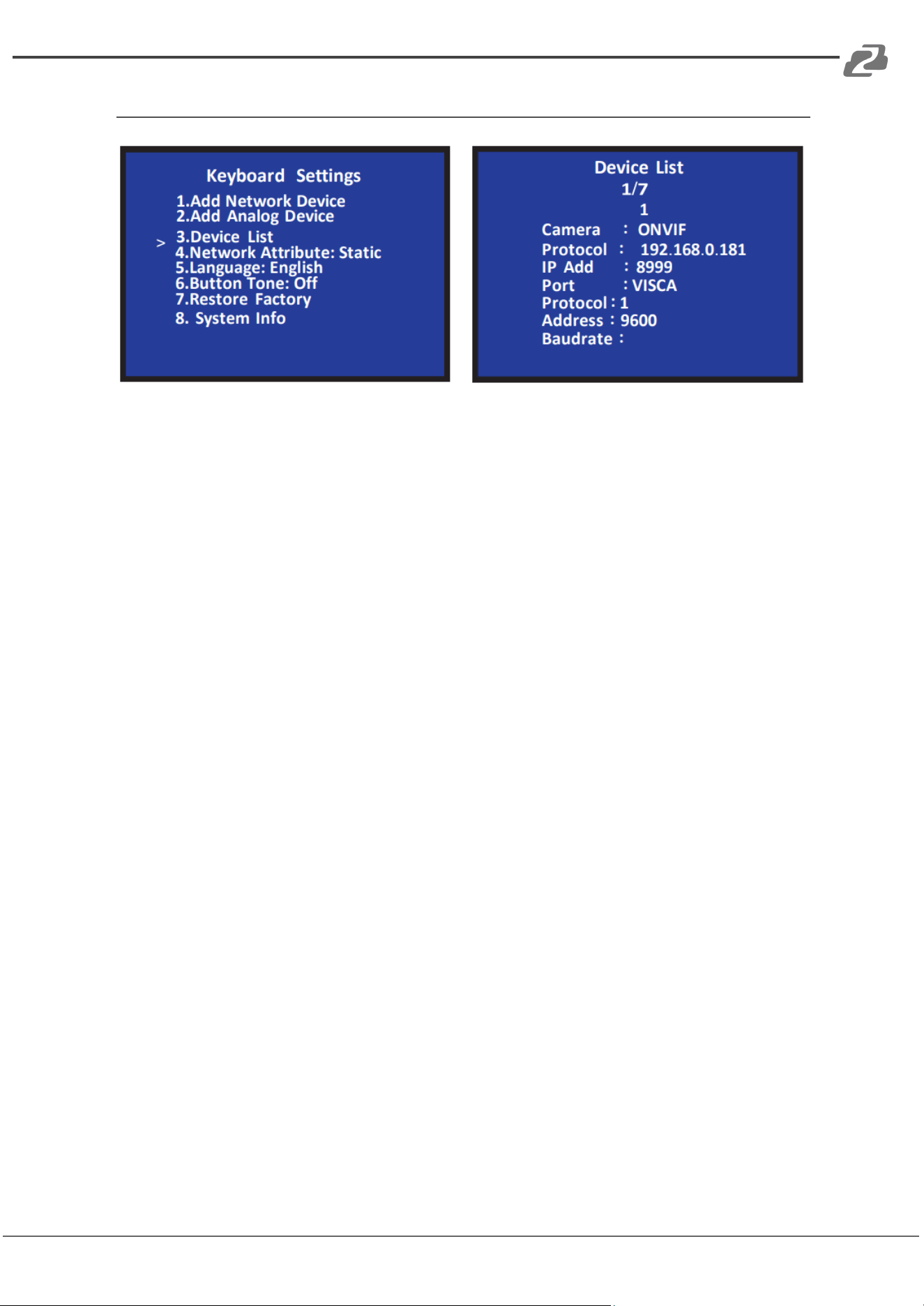
Device List
1. Press the [SETUP/MENU] button to enter the settings interface, move the joystick
up and down to select option 3 Device List press the [ENTER] button to view the
added devices.
2. Review the saved devices by moving the joystick up and down, press the button on
top of the joystick handle or the [ENTER] button to select the camera to be
controlled.
3. When the screen shows that the connection is successful, the controller has been
connected to this IP device and can be controlled.
Address: 830 National Drive #140, Sacramento, CA 95834, USA · Tel: +1(888)499-9906 · Email: support@bzbgear.com 15
BZBGEAR BG-Commander PRODUCT MANUAL
Network Configuration
The computer must be on the same subnet as the controller to connect successfully. The
device will not be accessible otherwise. The controller default IP address is 192.168.5.180,
therefore the computer must also be connected to the 192.168.5.x subnet.
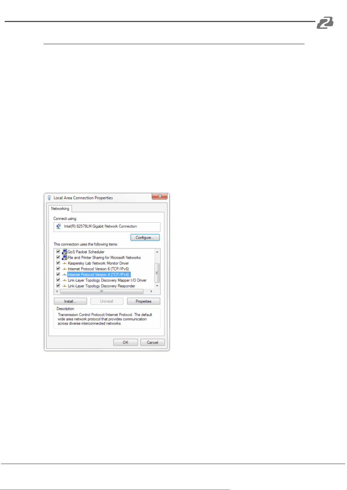
To connect to the controller, open the Local Area Connection Properties on the computer.
For Windows 10 users right-click on the internet connection in the lower right corner of the
desktop.
Select “Open Network & Internet Settings.”
Select “Change Adapter Options.”
Right-click on your connection (Wi-Fi or Ethernet) and select “Properties.”
Select “Internet Protocol Version 4 (TCP/IPv4) as shown below and click “Properties.”
Address: 830 National Drive #140, Sacramento, CA 95834, USA · Tel: +1(888)499-9906 · Email: support@bzbgear.com 16
BZBGEAR BG-Commander PRODUCT MANUAL
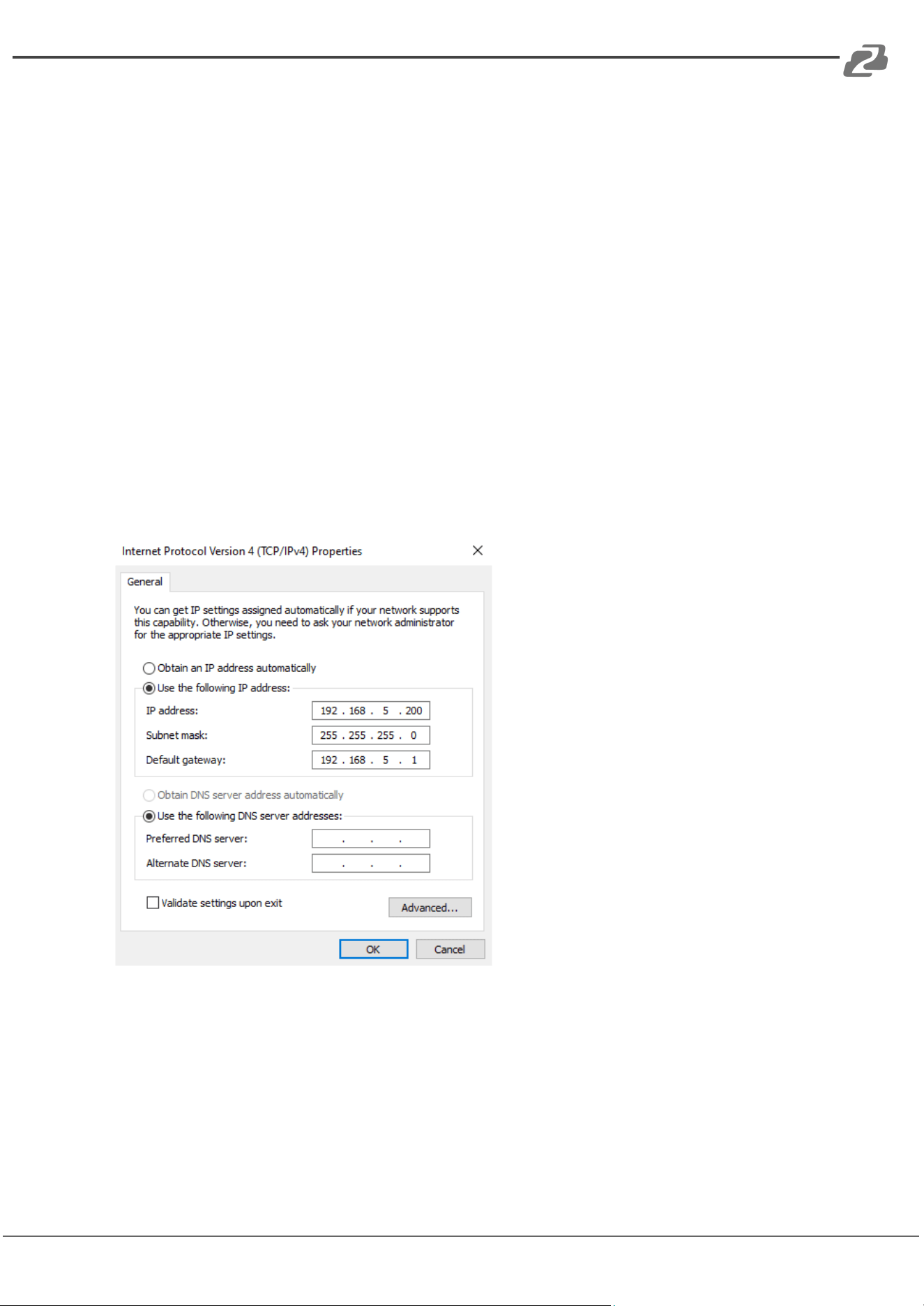
For the following steps refer to the diagram below.
Click on the bubble for “Use the following IP address”
In the IP address field enter a non-conflicting IP address on the same subnet as the
camera. If there is another device with the same IP address you will not be able to connect.
In the example below we are using 192.168.5.200
In the Subnet mask field enter 255.255.255.0
In the Default gateway field type 192.168.5.1
You can leave the DNS fields blank.
Click OK to apply your settings.
NOTE: When you are finished configuring the camera you will need to return to this screen
and click the bubbles for “Obtain an IP address automatically” and “Obtain DNS server
automatically” to restore internet connectivity to your computer. Also make sure to
reconnect any ethernet cables you may have unplugged.
Address: 830 National Drive #140, Sacramento, CA 95834, USA · Tel: +1(888)499-9906 · Email: support@bzbgear.com 17

BZBGEAR BG-Commander PRODUCT MANUAL
Homepage Connection and Login
Connect the power cable of the controller and connect a network cable (NOTE: only the
network cable is needed if connected to a PoE switch).
After the controller boot sequence is complete, the BG-Commanders’ IP address will be
displayed on top of the screen as the “NATIVE IP.”
Default login information
Username: admin
Password: none
1. Connect the controller and computer to the same network. Enter this IP address into
your web browser to access the configuration page (shown below) and enter the default
credentials.
Address: 830 National Drive #140, Sacramento, CA 95834, USA · Tel: +1(888)499-9906 · Email: support@bzbgear.com 18
BZBGEAR BG-Commander PRODUCT MANUAL
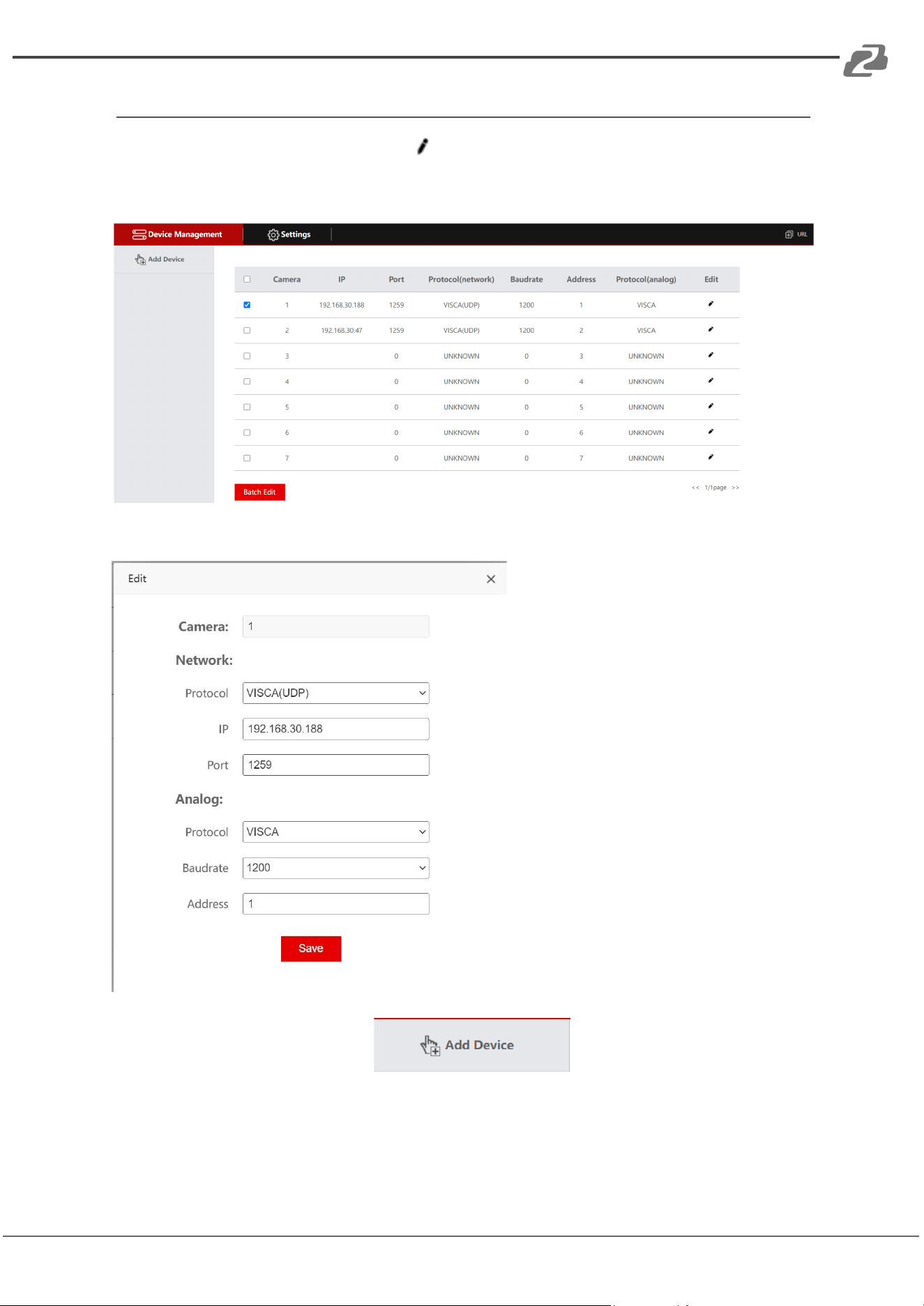
Device Management
On the “Device Management” tab click button to add or edit PTZ cameras 1 - 7
connected to the controller. Depending on the connection from the controller to the camera
only one section, Network or Analog, will need to be configured (see below).
Network:
1. Select the camera protocol
2. Enter the camera IP address
3. Enter the camera port
Analog:
1. Select the camera protocol
2. Select the camera baudrate
3. Enter the camera address
To add cameras 8 - 256 press the button in the top left of the
interface.
Use the “Batch Edit” or “Batch Delete” buttons to edit or delete multiple selected cameras.
Address: 830 National Drive #140, Sacramento, CA 95834, USA · Tel: +1(888)499-9906 · Email: support@bzbgear.com 19
BZBGEAR BG-Commander PRODUCT MANUAL
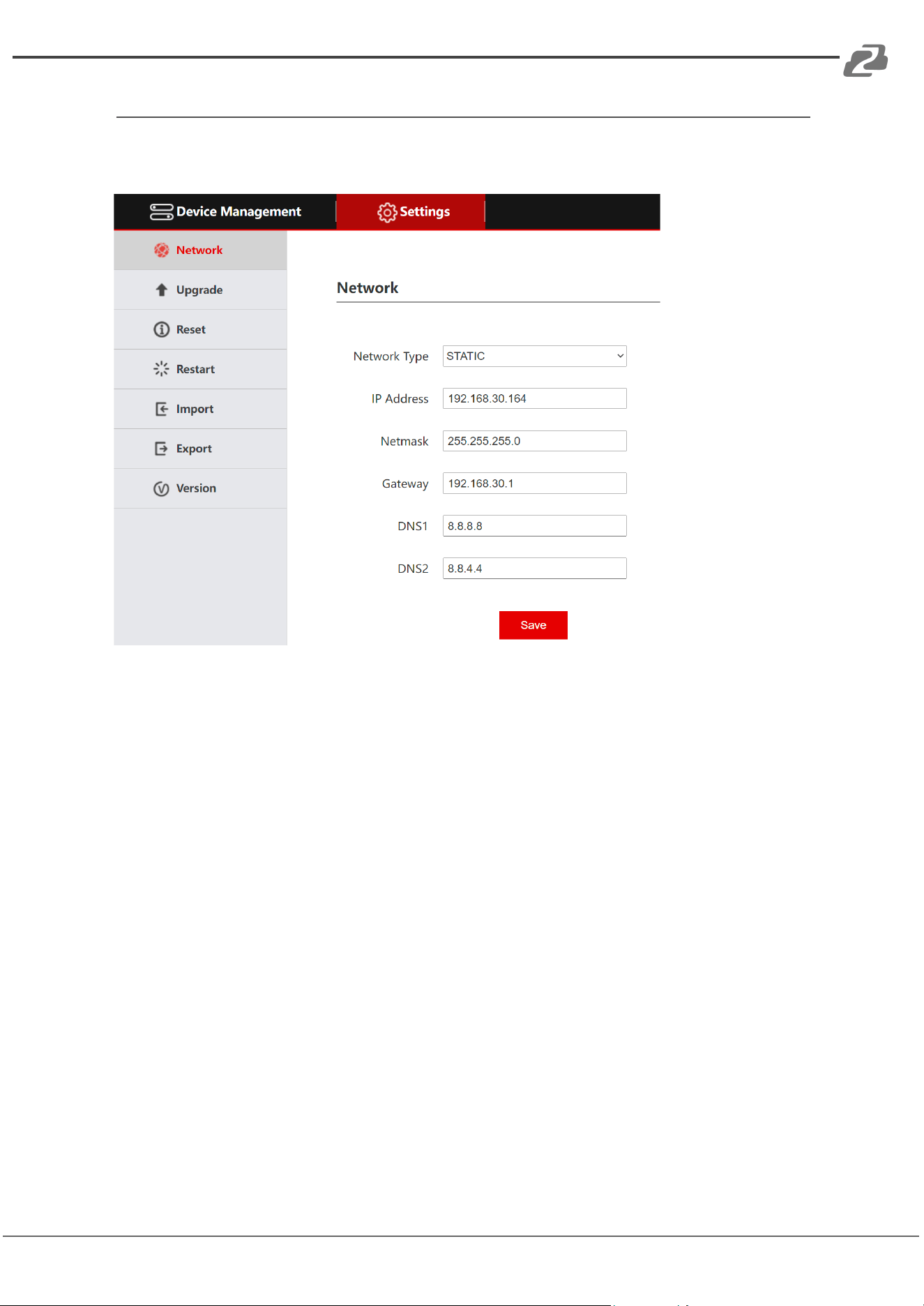
Network Settings
LAN settings of the controller can be modified by clicking the Settings Tab and then
selecting Network from the left-hand menu.
Network Type: Can be set to DHCP or Static.
DHCP: DHCP is off by default, but when enabled, the controller will be automatically
assigned an IP address from the network if a DHCP server is present. (NOTE: The other
fields cannot be configured and are grayed out)
STATIC: Enter a user defined IP Address, Netmask, and Gateway.
NOTE: After any changes are made you must click the “Save” button, the controller will
restart, and you will be redirected to the login screen.
Address: 830 National Drive #140, Sacramento, CA 95834, USA · Tel: +1(888)499-9906 · Email: support@bzbgear.com 20
BZBGEAR BG-Commander PRODUCT MANUAL
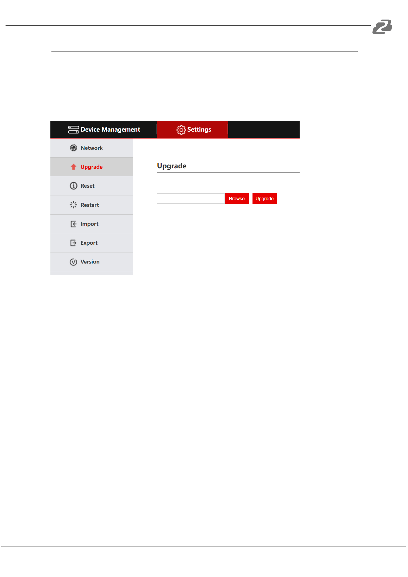
System Upgrade
The upgrade tab is used for performing firmware updates. Select “Browse” to locate the
correct upgrade file and then click “Upgrade.” After the upgrade is complete, the device will
automatically restart.
NOTE: Do not perform any operations on the device during its upgrade and do not power
off or disconnect from the network.
Address: 830 National Drive #140, Sacramento, CA 95834, USA · Tel: +1(888)499-9906 · Email: support@bzbgear.com 21
BZBGEAR BG-Commander PRODUCT MANUAL
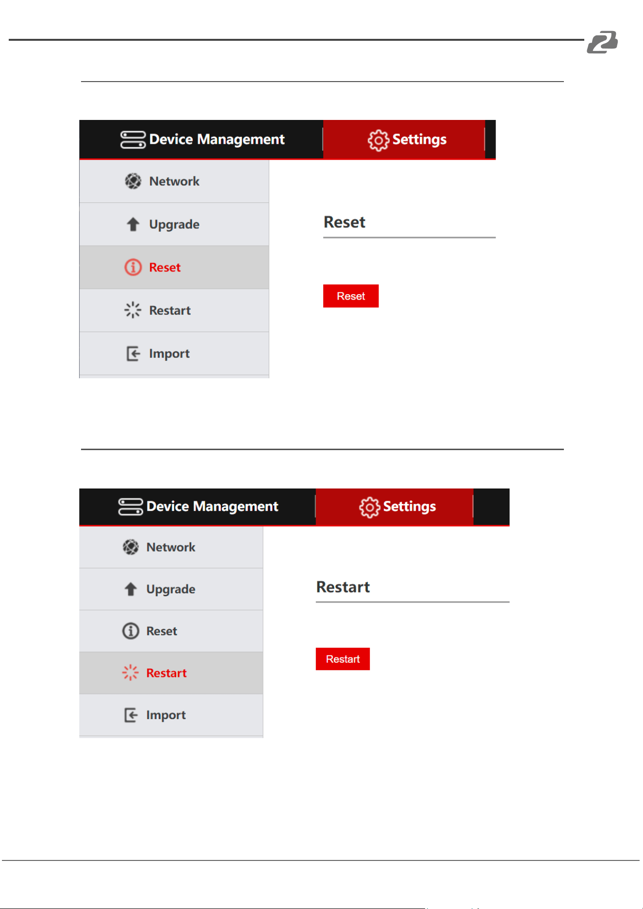
Reset
Click “Reset” to restore the device to factory settings and clear all added devices.
Restart
Click “Restart” to perform a system reboot of the controller.
Address: 830 National Drive #140, Sacramento, CA 95834, USA · Tel: +1(888)499-9906 · Email: support@bzbgear.com 22
BZBGEAR BG-Commander PRODUCT MANUAL
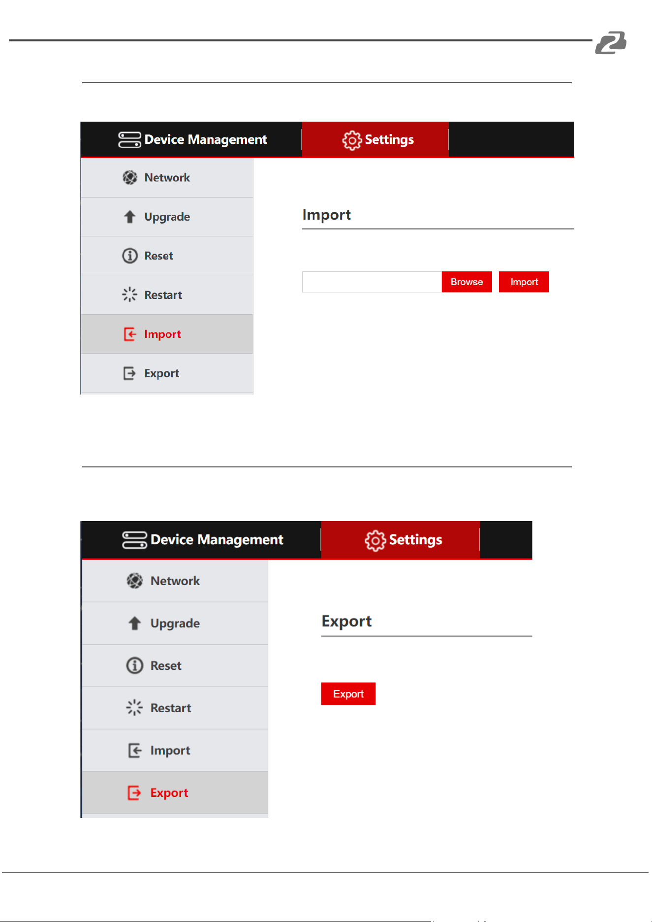
Import Configuration
Import a previous configuration.
Export Configuration
Export the information of the current controllers’ added devices and can be imported to
other controllers.
Address: 830 National Drive #140, Sacramento, CA 95834, USA · Tel: +1(888)499-9906 · Email: support@bzbgear.com 23
BZBGEAR BG-Commander PRODUCT MANUAL
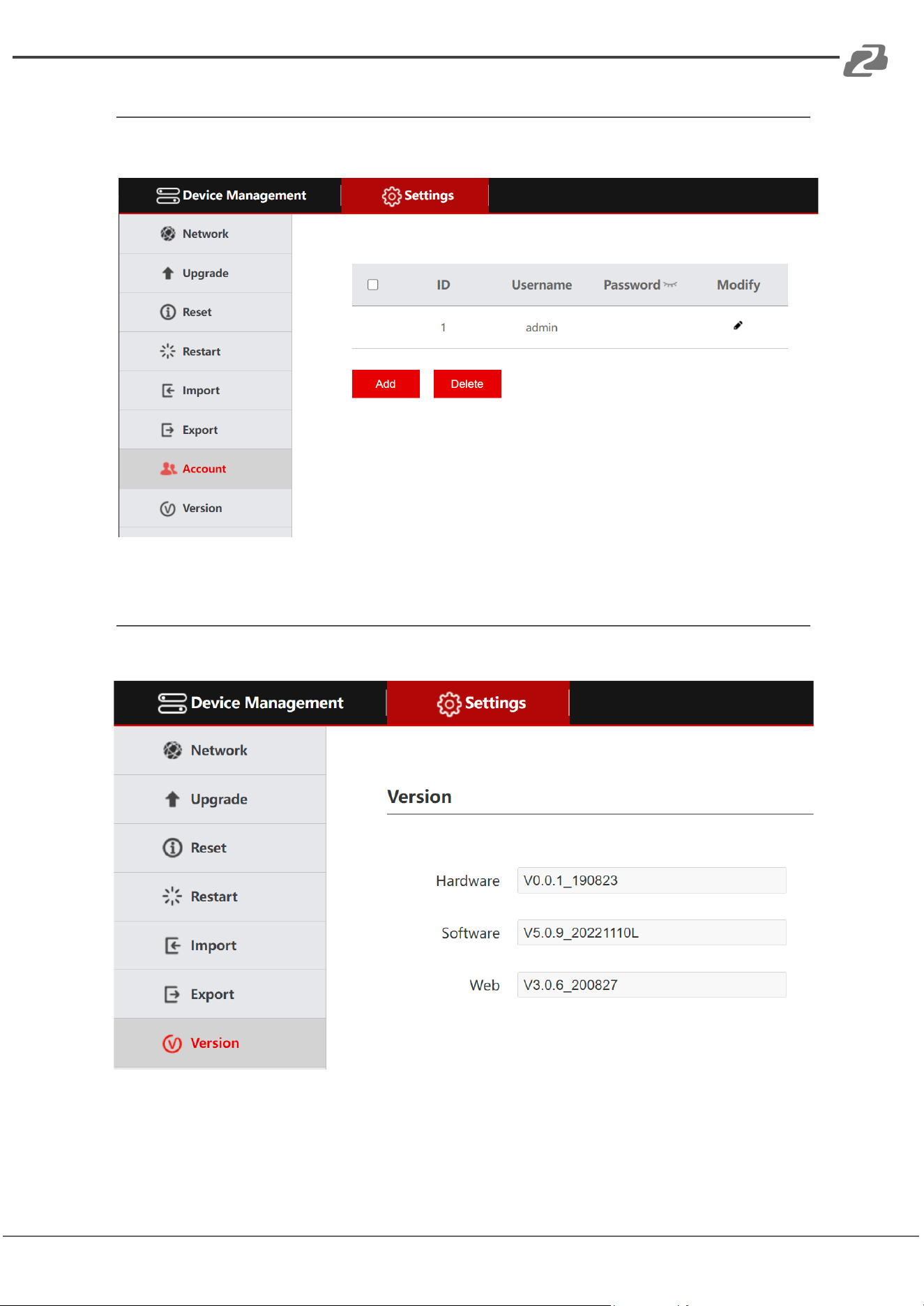
Account
Modify, Add, or Remove user accounts for the web interface.
Version
Display the software and hardware information of the current controller.
Address: 830 National Drive #140, Sacramento, CA 95834, USA · Tel: +1(888)499-9906 · Email: support@bzbgear.com 24

BZBGEAR BG-Commander PRODUCT MANUAL
Troubleshooting
1. If the screen displays "Connection failed", check that IP information is correct for the
camera. Verify the controller and camera are on the same subnet.
2. If the screen displays "Username and password are incorrect", please check
whether the added device username and password are correct.
3. If the camera does not respond to the joystick while in VISCA UDP mode enter the
controller setup menu and set option 9: VISCA RESPONSE to DISABLE.
Address: 830 National Drive #140, Sacramento, CA 95834, USA · Tel: +1(888)499-9906 · Email: support@bzbgear.com 25

BZBGEAR BG-Commander PRODUCT MANUAL
Tech Support
Have technical questions? We may have answered them already!
Please visit BZBGEAR’s support page (bzbgear.com/support) for helpful information and
tips regarding our products. Here you will find our Knowledge Base
(bzbgear.com/knowledge-base) with detailed tutorials, quick start guides, and step-by-step
troubleshooting instructions. Or explore our YouTube channel, BZB TV
(youtube.com/c/BZBTVchannel), for help setting up, configuring, and other helpful how-to
videos about our gear.
Need more in-depth support? Connect with one of our technical specialists directly:
Phone
1.888.499.9906
Email
support@bzbgear.com
Live Chat
bzbgear.com
Limited Product Warranty Terms
Pro Line: 5-year warranty from the date of purchase for AV/Broadcasting products bought
on or after August 1, 2024.
Essential Line: 3-year warranty from the date of purchase for AV/Broadcasting products
bought on or after August 1, 2024.
Cables: Lifetime Limited Product Warranty.
For complete warranty information, please visit bzbgear.com/warranty.
For questions, please call 1.888.499.9906 or email support@bzbgear.com.
Mission Statement
BZBGEAR is a breakthrough manufacturer of high-quality, innovative audiovisual equipment
ranging from AVoIP, professional broadcasting, conferencing, home theater, to live
streaming solutions. We pride ourselves on unparalleled customer support and services.
Our team offers system design consultation, and highly reviewed technical support for all
the products in our catalog. BZBGEAR delivers quality products designed with users in
mind.
Copyright
All the contents in this manual and its copyright are owned by BZBGEAR. No one is allowed
to imitate, copy, or translate this manual without BZBGEAR’s permission. This manual
contains no guarantee, standpoint expression or other implies in any form. Product
specification and information in this manual is for reference only and subject to change
without notice.
All rights reserved. No reproducing is allowed without acknowledgement.
Address: 830 National Drive #140, Sacramento, CA 95834, USA · Tel: +1(888)499-9906 · Email: support@bzbgear.com 26