
USE AND CARE MANUAL
COOK
LIKE
A
GOD
OUTDOOR KITCHEN
MK01SS304 | MK02SS304 | MK03SS304 | MK04SS304 | MK06SS304 | MK07SS304

OUTDOOR KITCHEN
SUITE
USE AND CARE MANUAL
MK01SS304 | MK02SS304 | MK03SS304
MK04SS304 | MK06SS304 | MK07SS304

service@thorgroup.us +1 877-288-8099
Warnings
These are the most critical warnings summarized below.
***WARNING***
• If the instructions in this manual are not followed exactly, a fire or explosion
may result, causing property damage, personal injury or death.
• Do not store or use gasoline or other flammable substances and liquids near
this or other appliance,
• Installation of this appliance must be done by a qualified, service agency or gas
supplier.
What to do if you smell gas
• Do not light any appliance
• Do not touch an electrical switch
• Immediately call the gas supplier from a neighbor’s phone
• Follow the gas supplier’s instructions
• If you cannot reach the gas supplier, call the fire department

service@thorgroup.us +1 877-288-8099
Welcome
Thank you for purchasing your Thor Kitchen Appliance! We appreciate your
business and we recommend that you read this entire User’s Manual before
operating your new appliance for the first time.
This manual contains instructions on how to properly install and set up your new
range, as well as insights into the unique features that our product offers. Please
keep this manual for future reference, as it contains answers to questions that you
might have as you begin to cook.
For any inquiries, please reach our customer service support at +1 877-288-8099
Thank you,
Thor Group
This manual applies to the following models’ series:
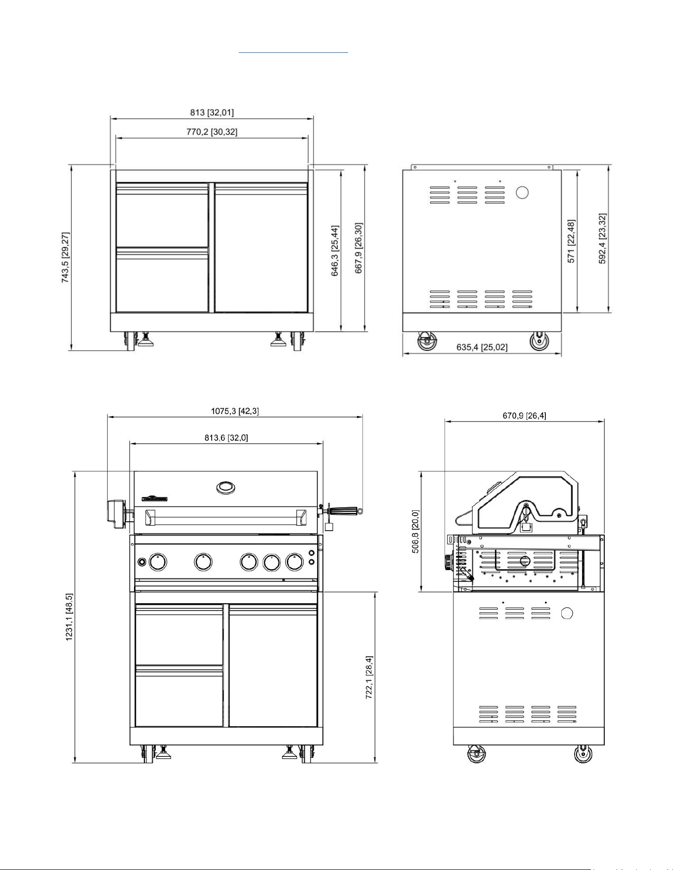
Model # MK03SS304 (Outdoor Grill Cabinet)
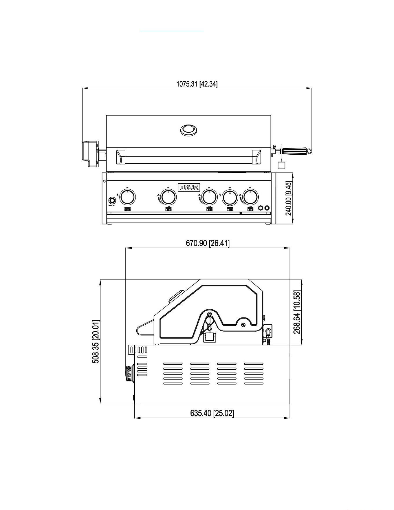
Model # MK04SS304 (Outdoor BBQ Grill)
service@thorgroup.us +1 877-288-8099
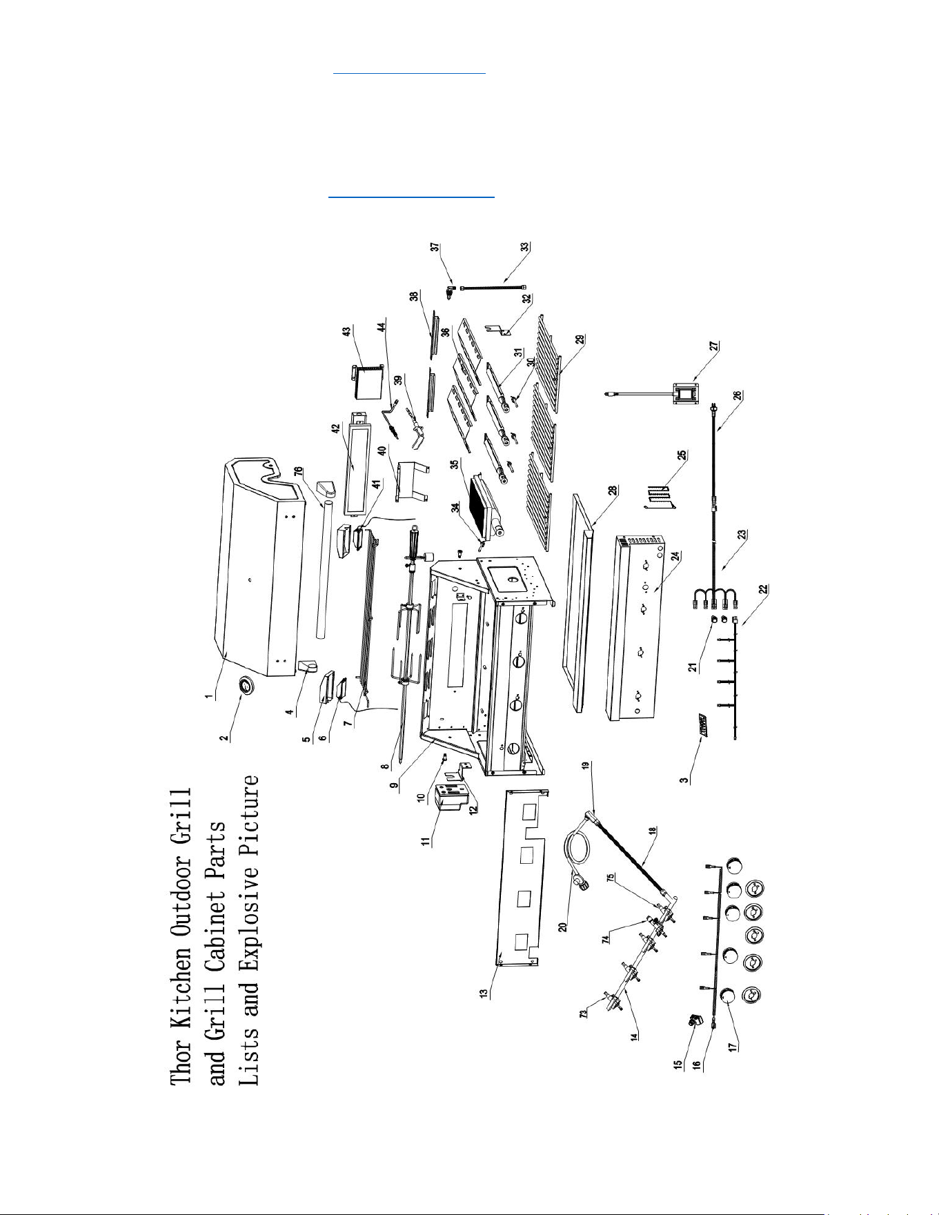
Parts Explosive Pictures
If you are missing any part, please contact Thor Kitchen Customer Service Department at +1 877-288-
8099 at business hours, or email se[email protected] for help. Please provide your proof of purchase
for warranty verification.

service@thorgroup.us +1 877-288-8099
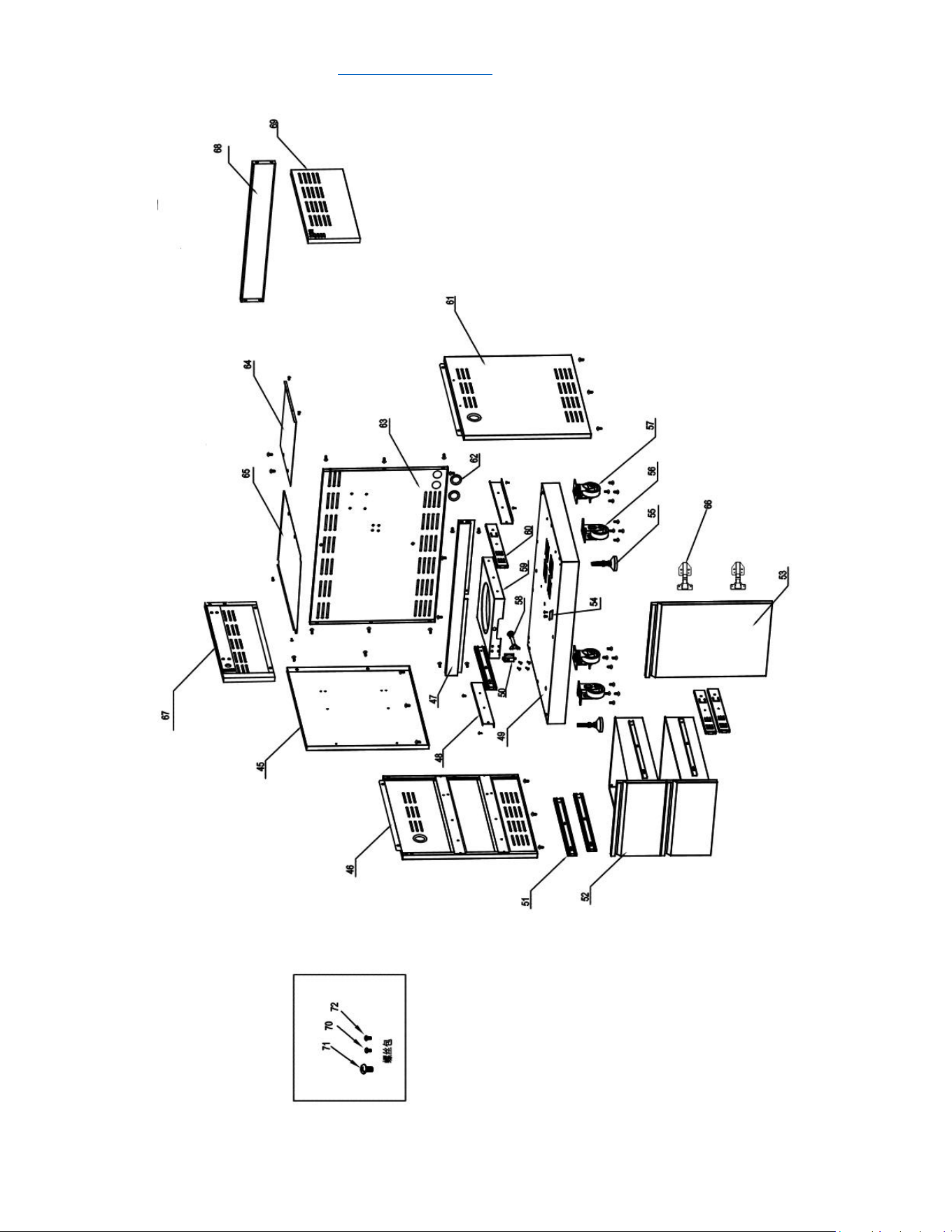
Parts List
Explosive
#
Part #
Part Name
Quantity
1
22.99.008092-000-A0
Grill Top Cover
1
2
05.99.008024-000-A0
Thermometer
1
3
08.01.008041-000-A0
logo
1
4
12.02.000070-000-A0
left handle holder
1
5
04.01.008107-000-A0
Light Cover
2
6
07.04.008001-000-A0
Light #1
1
7
13.99.008002-000-A0
Top warming rack
1
8
05.99.008011-000-A0
Rotisserie
1
9
22.99.009207-000-A0
Grill Cavity
1
10
06.07.008002-000-A1
Top cover rotary pin
2
11
07.14.008001-000-A0
Motor
1
12
04.01.008057-000-A0
Motor holder
1
13
04.03.008002-000-A1
Burner valve holding plate
1
14
22.99.009209-000-A0
Main manifold
1
15
07.07.008004-000-A0
5-point Spark Module
1
16
07.06.008003-000-A0
Main burner ignition harness
1
17
14.01.008001-000-A0
Main Burner Knob
5
18
11.01.008001-000-A0
corrugated pipe
1
19
05.07.008001-000-A0
Embedded joint
1
20
07.99.000266-000-A0
Gas regulator and gas pipe
1
21
07.02.008012-000-A0
Metal push button
2
22
07.06.008006-000-A0
Main burner knob light wiring
1
23
07.06.008002-000-A0
Main switch wiring
1
24
19.07.008002-000-A0
Grill control panel
1
25
05.09.008002-000-A0
match holder
1
26
07.06.008005-000-A0
Main burner power plug
1
27
07.14.008002-000-A0
American-standard transformer
1
28
20.01.008015-000-A2
Grease tray
1
29
13.02.008002-000-A0
Cooking rack
1
30
10.09.008009-000-A0
Main burner electrode
3
31
10.01.008002-000-A2
Tube burner
3
32
04.01.008058-000-A0
Rotisserie holder
1
33
10.04.008002-000-A0
Back broil burner corrugated pipe
1
34
10.09.008010-000-A0
Front broil burner electrode
1
35
10.10.008007-000-A0
Infrared broil burner
1

service@thorgroup.us +1 877-288-8099
36
04.01.008051-000-A0
flame tamer
3
37
10.05.008002-000-A0
Back broil burner orifice - LP
1
38
20.01.008014-000-A1
flame transferring welding plate
2
39
10.09.008004-000-A0
Back broiler burner electrode
1
40
04.01.008060-000-A1
Back broiler burner protection cover
1
41
07.04.008002-000-A0
Light #2
1
42
10.99.008001-000-A0
Back broil burner
1
43
04.01.008053-000-A0
gas-collecting hood
1
44
10.99.008002-000-A0
Temperature rod
1
45
20.01.008086-000-A0
Clapboard welding part
1
46
20.01.008082-000-A0
Left side panel A welding assembly
1
47
20.01.008087-000-A0
beam welding assembly
1
48
04.01.008119-000-A0
LP tank supporting slide
2
49
20.01.008079-000-A0
tank bottom welding assembly
1
50
05.17.008003-000-A0
Snap bolt
1
51
05.14.008001-000-A0
Slideway
4
52
22.99.009199-000-A0
Drawer assembly
2
52.1
20.01.008051-000-A0
drawer front panel welding plate
2
52.2
04.01.008179-000-A0
drawer front panel lining
2
52.3
04.01.008180-000-A0
drawer middle plate
2
52.4
04.01.008181-000-A0
drawer bottom plate
2
53
22.99.009217-000-A0
Door assembly
1
54
04.01.002596-000-A1
Door barrier strip
1
55
05.01.008004-000-A0
Supporting leg
2
56
05.10.000122-000-A0
Fixed caster
2
57
05.10.000123-000-A0
Universal caster with Brake
2
58
05.13.008153-000-A0
Tank fixing rod
1
59
04.01.008117-000-A0
Tank bottom support
1
60
05.14.008012-000-A0
14" Sliders
4
61
20.01.008080-000-A0
Right side panel A welding assembly
1
62
06.08.008078-000-A0
Rubber gasket
4
63
20.01.008084-000-A0
Back panel A welding assembly
1
64
04.01.008183-000-A0
gas tank heat shield
1
65
04.01.008182-000-A0
Laminate board
1
66
05.03.008001-000-A0
Door Hinge
2

service@thorgroup.us +1 877-288-8099
67
20.01.008083-000-A0
Left side panel B welding assembly
1
68
20.01.008085-000-A0
Back Panel B welding assembly
1
69
20.01.008081-000-A0
Right side panel B welding assembly
1
70
06.10.000022-000-A0
5/32“Philips thumb head screw
52
71
06.02.000093-000-A0
1/4“*14 Philips thumb head screw with anti-
slip design
59
72
06.11.008056-000-A0
5/32" *8 flat head screw
12
73
09.01.008008-000-A0
front broil burner valve
1
74
09.04.008003-000-A0
back broil burner valve
1
75
09.01.008007-000-A0
main burner valve
3
76
12.01.008002-000-A0
Top cover handle
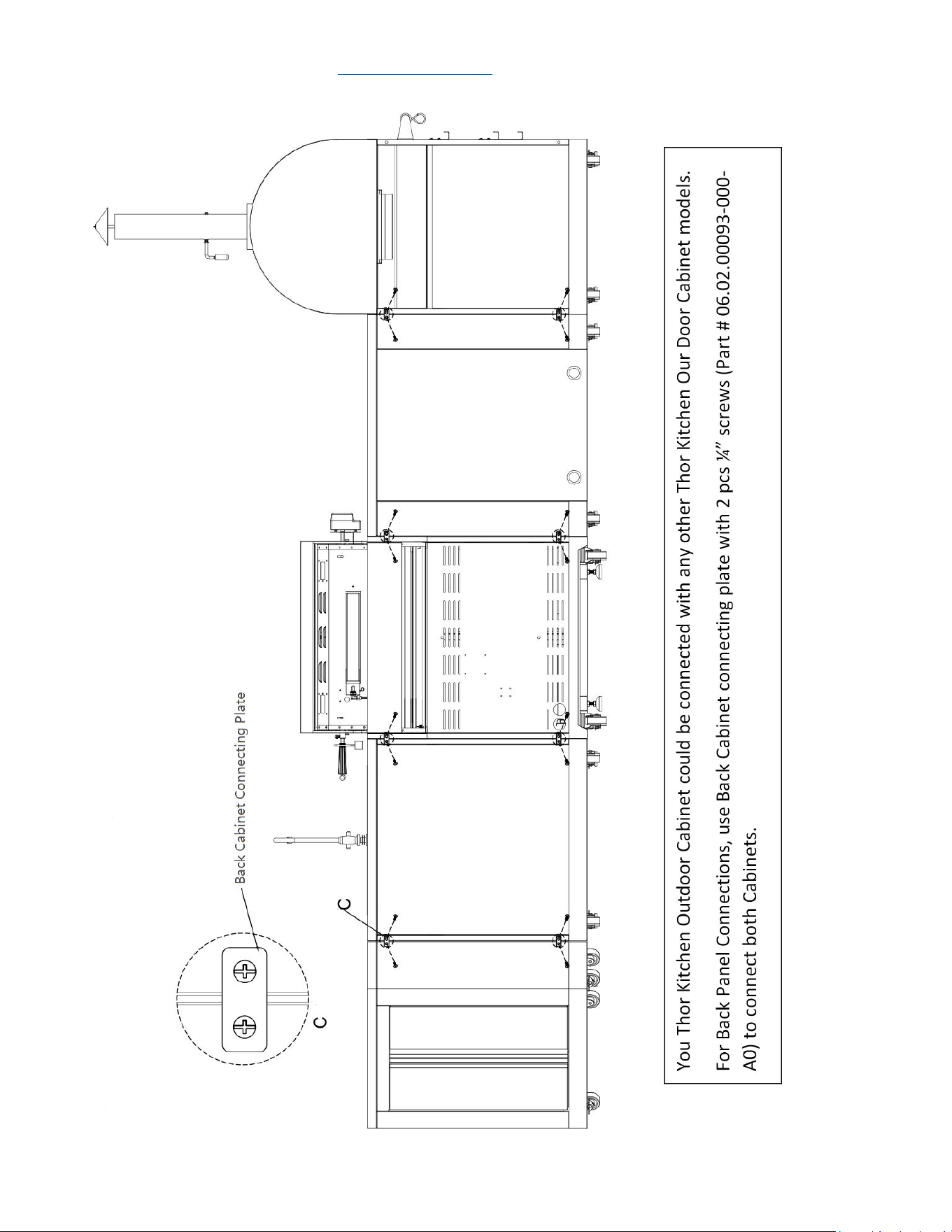
1
77
04.01.002580-000-A0
cabinet back connecting plate
2
service@thorgroup.us +1 877-288-8099
Cabinet Installation
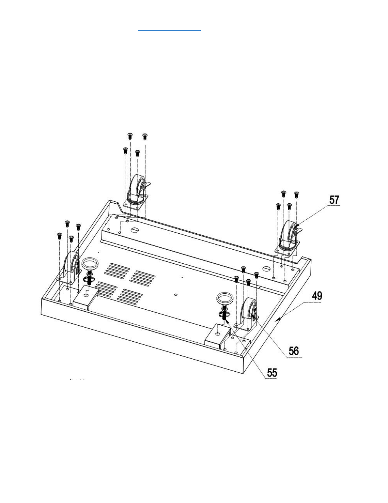
Step 1
1. Flip the bottom base welding assembly (Part #49) so in order to install legs and casters
2. Use 16 pcs ¼” *14 Philips thumb head screw with anti-slip design (Part #71) to install 2 pcs
supporting legs (Part #55), 2 pcs fixed casters (Part #56) and 2 pcs universal casters with brake (Part
#57)
service@thorgroup.us +1 877-288-8099
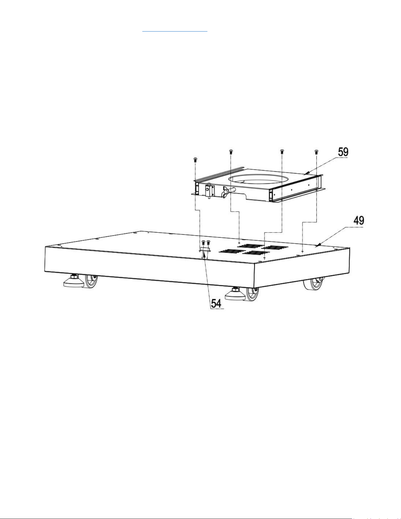
Step 2
1. Flip back the bottom base after casters and legs are installed;
2. Use 4 pcs 5/32” *8 flat head screw (Part # 72) to connect Tank bottom support (Part # 59) to
bottom base welding assembly (Part # 49);
3. Use 2 pcs 5/32” *8 flat head screw (Part # 72) to connect Door barrier strip (Part # 54) to
bottom base welding assembly (Part #49);
service@thorgroup.us +1 877-288-8099
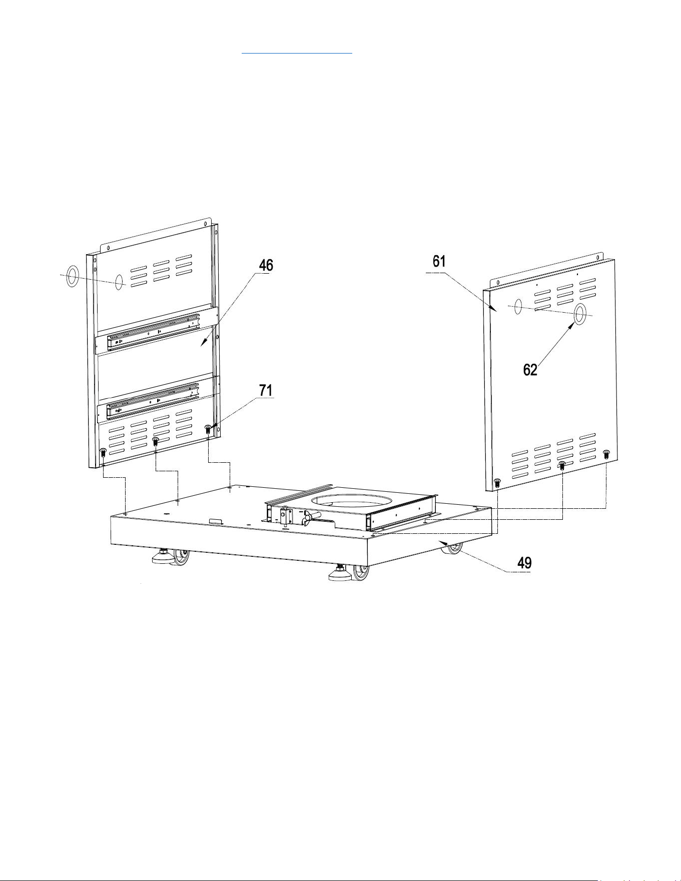
Step 3
1. Use 6 pcs 1/4“*14 Philips thumb head screw with anti-slip design (Part #71) to Left side panel A
welding assembly (Part #46) and Right-side panel A welding assembly (Part # 61) to bottom
base welding assembly (Part #49);
2. Attach 2 pcs Rubber gaskets to related position on Part #46 and Part #61;
service@thorgroup.us +1 877-288-8099
Step 4
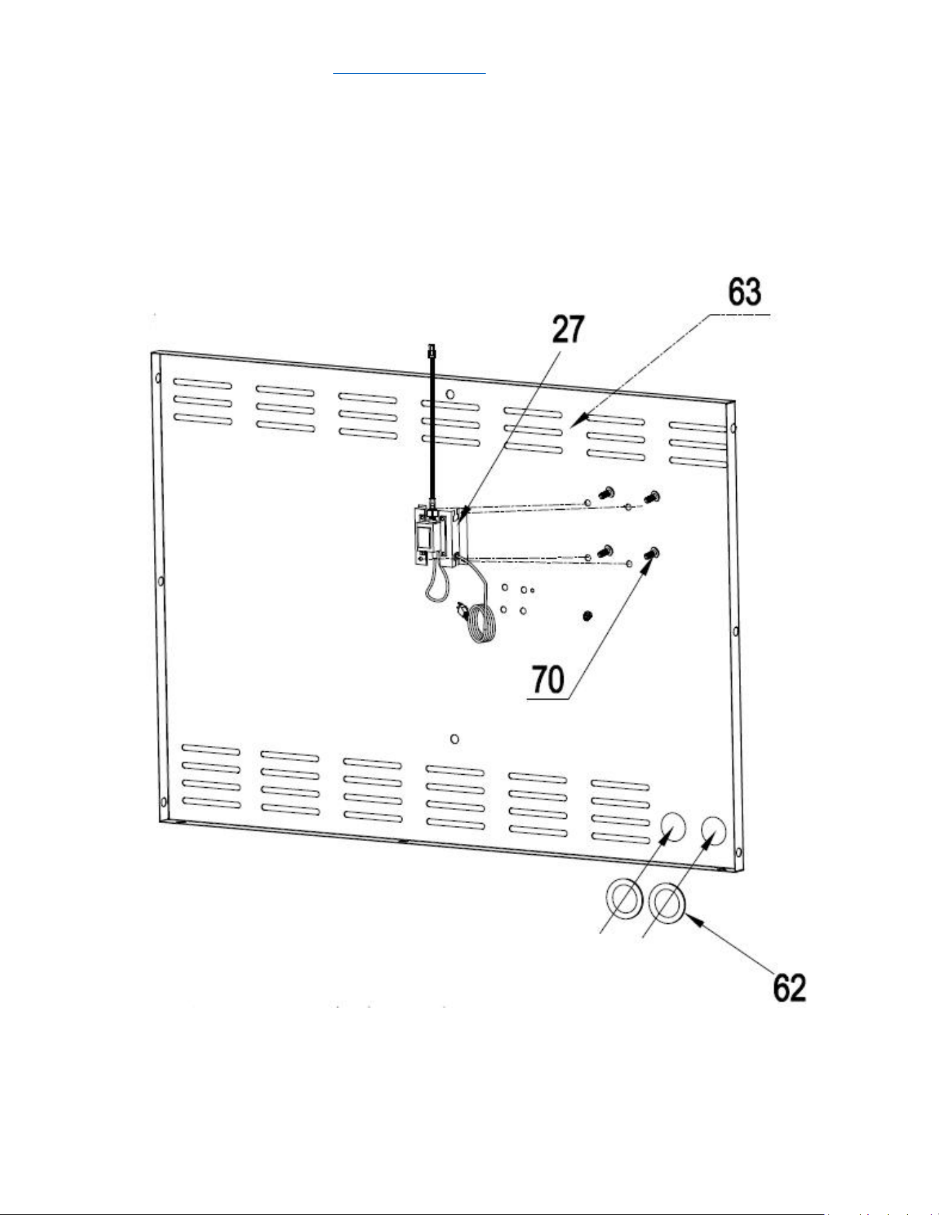
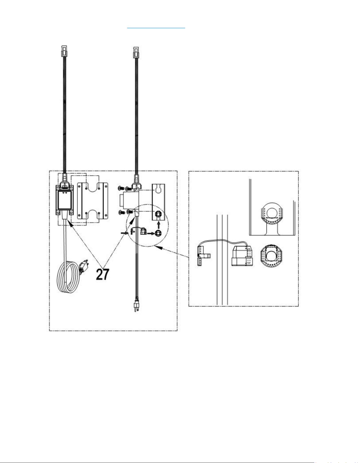
1. Use 4 pcs 5/32” *8 flat head screw (Part # 72) to install American-standard transformer (Part #
27) on Back panel A welding assembly (Part # 63); Do not break the power plug on the bottom
and the buckle on the top.
2. Attach 2 pcs Rubber gasket (Part # 62) to related position on Part # 63;
service@thorgroup.us +1 877-288-8099
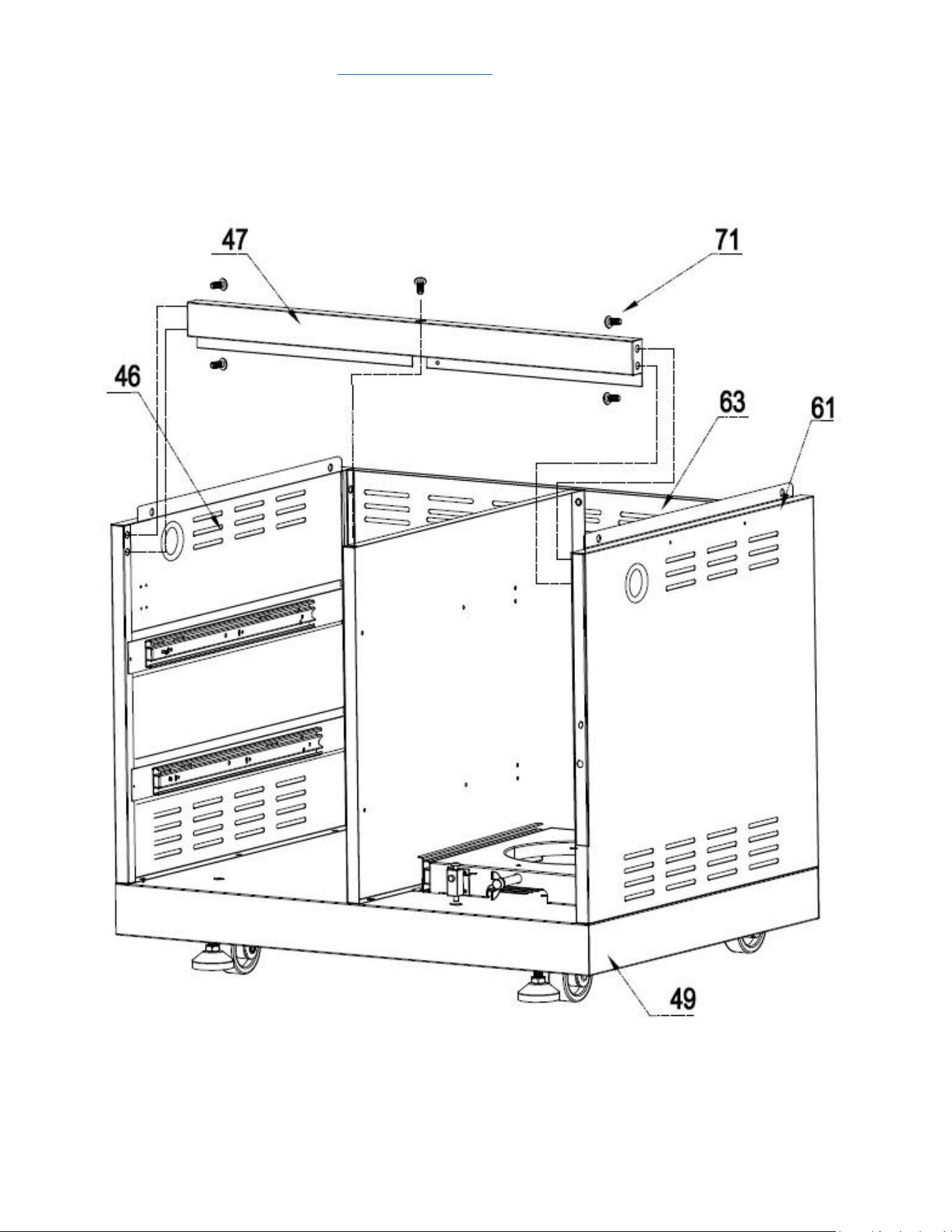
Step 5
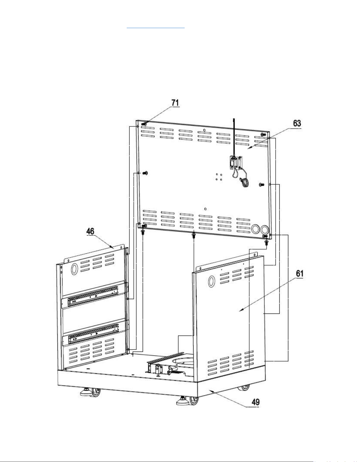
1. Use 3 pcs 1/4“*14 Philips thumb head screw with anti-slip design (Part #71) to install Back
panel A welding assembly (Part # 63) to bottom base welding assembly (Part # 49);
2. Use 3 pcs 1/4“*14 Philips thumb head screw with anti-slip design (Part #71) to connect Back
panel A welding assembly (Part # 63) with Part # 46 and # 61
service@thorgroup.us +1 877-288-8099
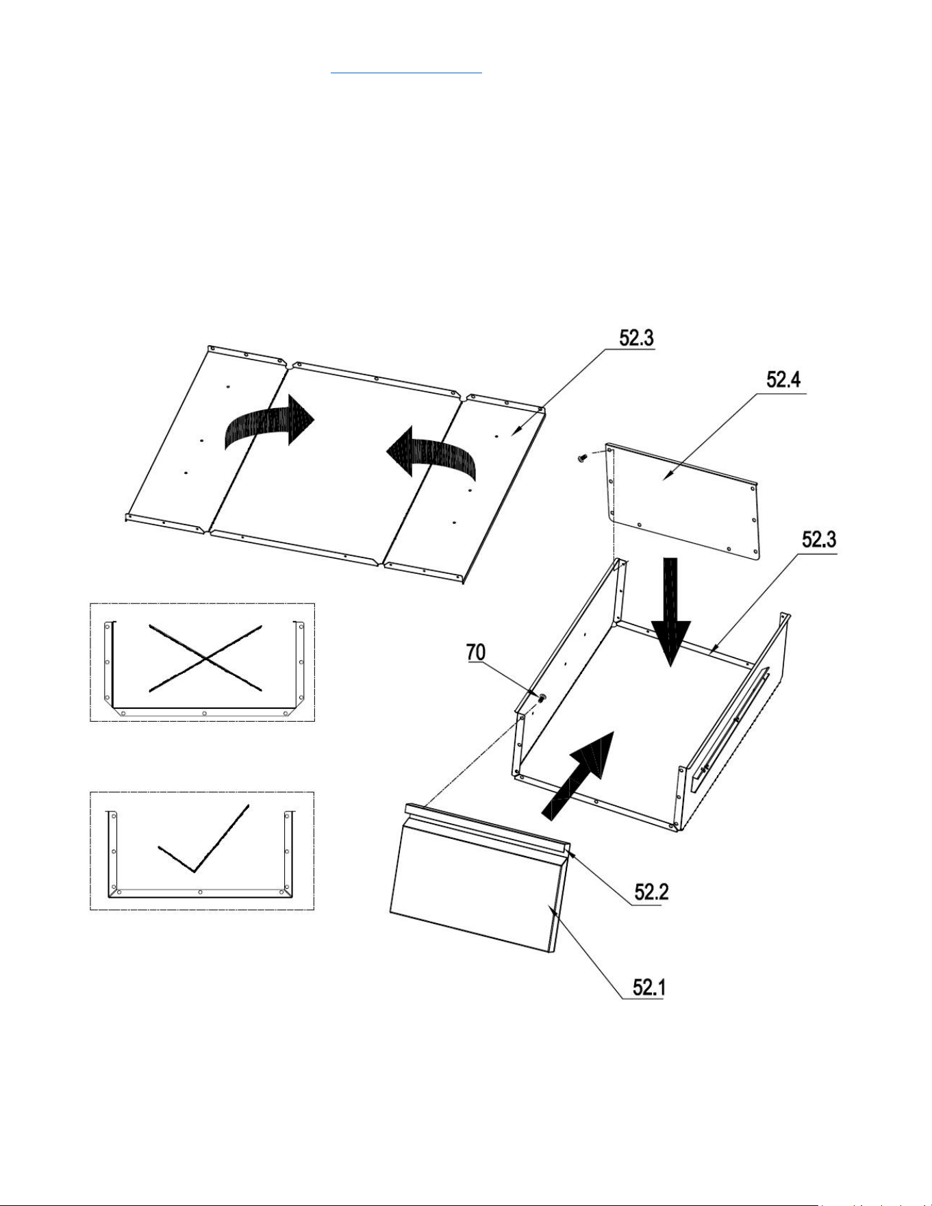
Step 8
1. Check the edge of the middle plate of the drawer assembly (Part #52) and make sure the side
with edge is facing up; otherwise you will get to wrong folding direction (see the picture below
with wrong folding direction with “×”). Be careful with the folding process.
2. Use 8 pcs 5/32 flat Philip’s screw heads (Part # 70) install the bottom plate of drawer assembly
(Part# 52.4) to the middle plate (Part# 52.3)
3. Use 8 pcs 5/32 flat Philip’s screw heads (Part # 70) install the front plate of drawer (Part#
assembly to the middle plate (Part# 52.1 and 52.2)
service@thorgroup.us +1 877-288-8099
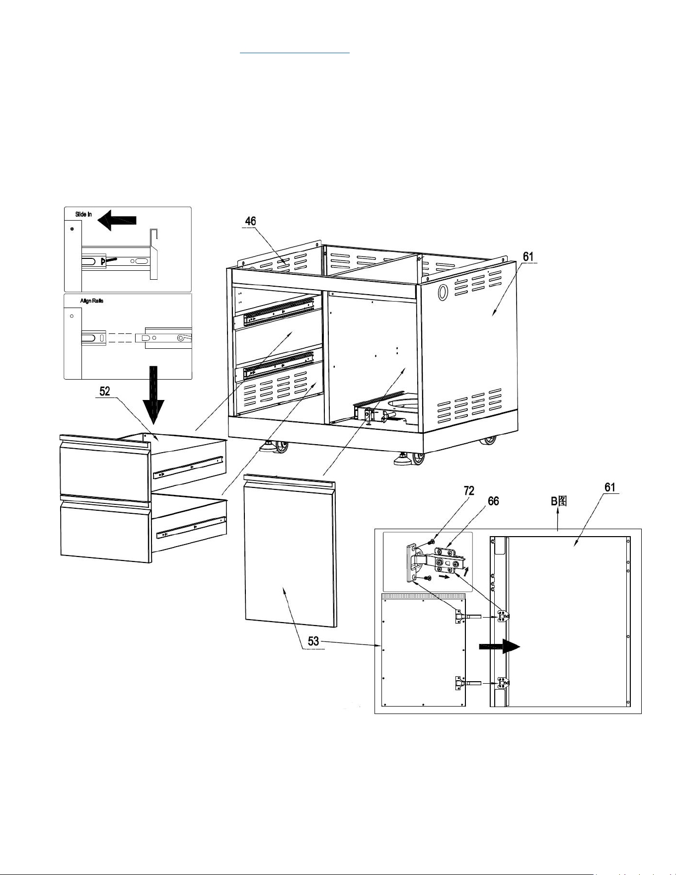
Step 9
1. Insert 2 pcs drawer assemblies (Part #52) into cabinet body;
2. Divide the two parts from door hinge (Part #66) and use 5/32” *8 flat head screw (Part #72) to install
them to right side panel (Part #61) and cabinet door (Part #53)
3. Follow the requirement in the picture to install cabinet door (Part # 53)
service@thorgroup.us +1 877-288-8099
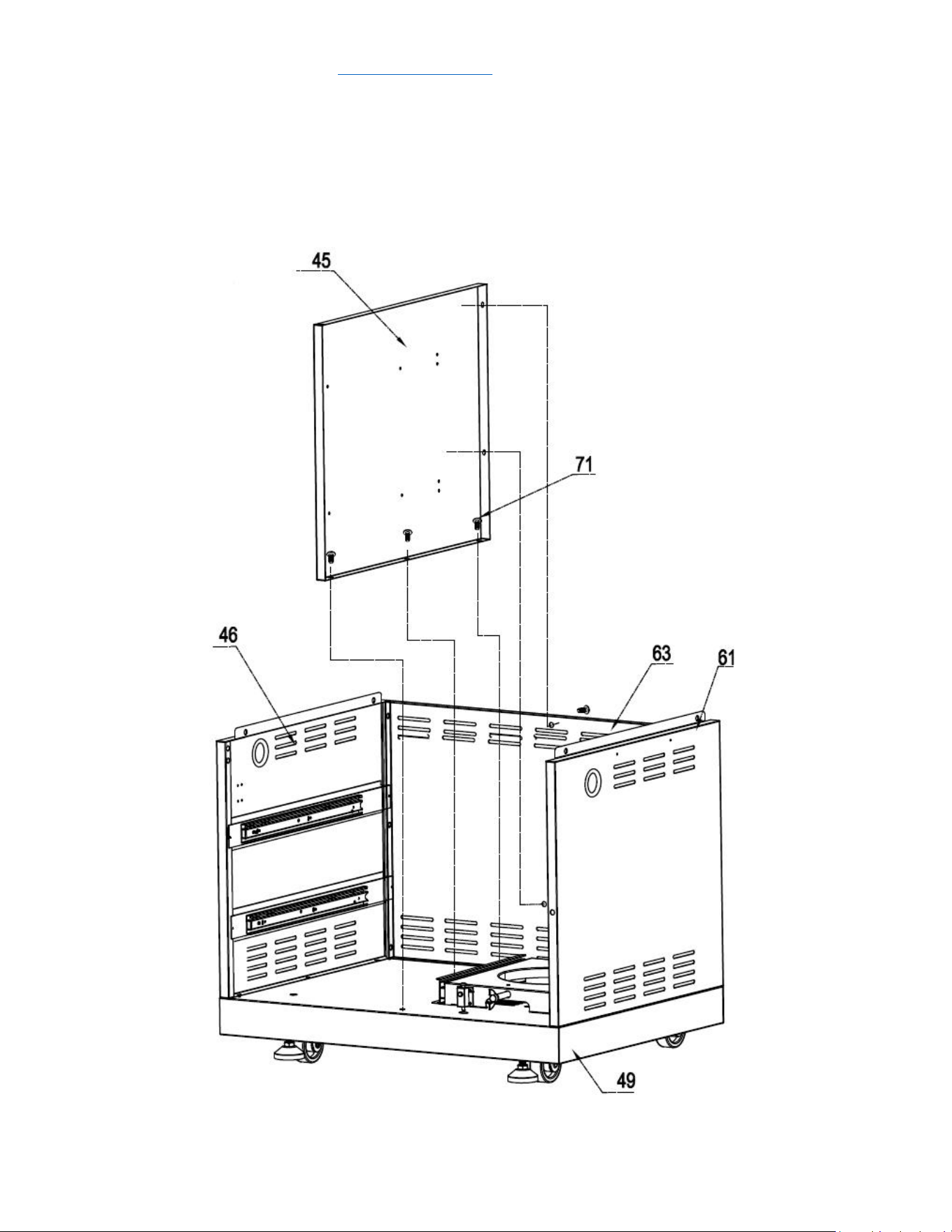
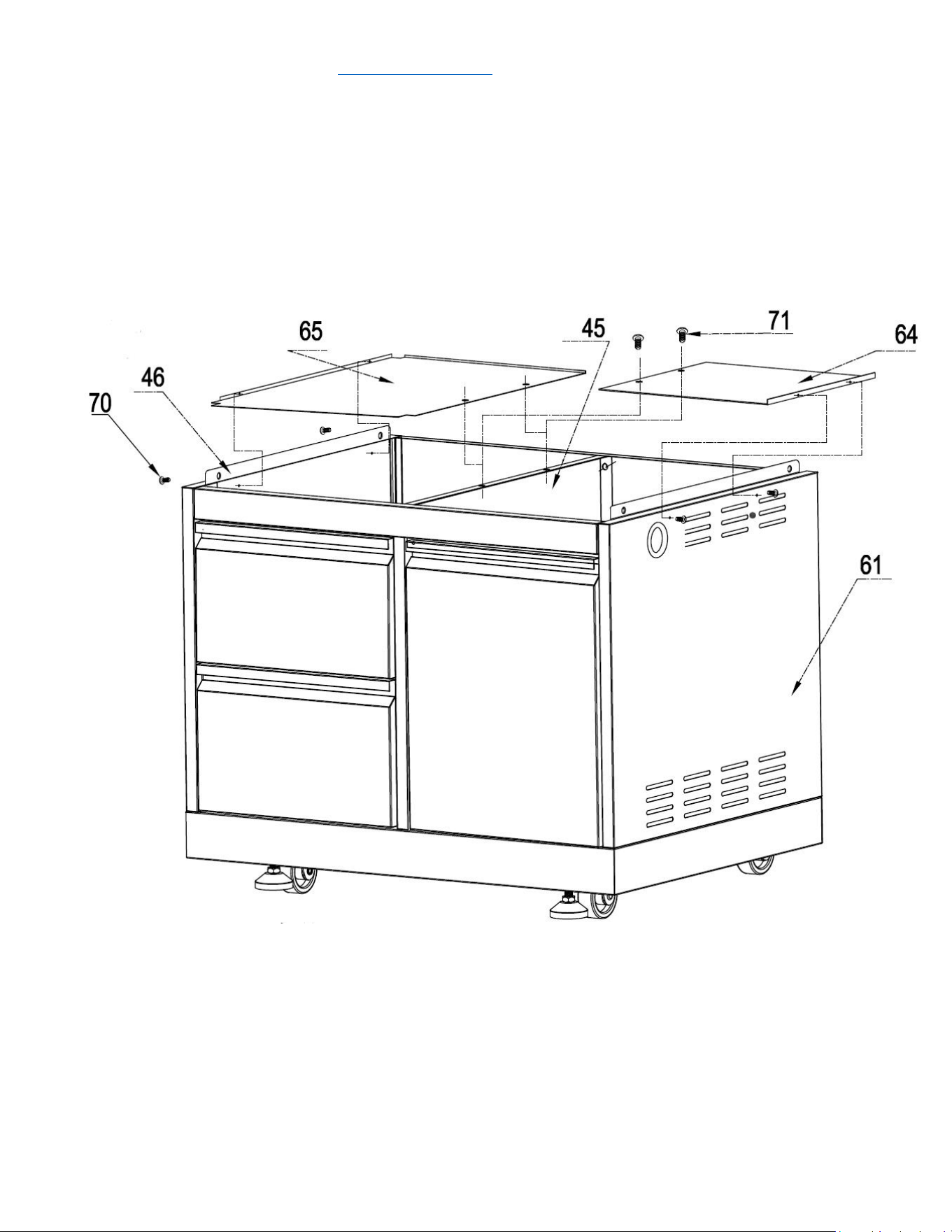
Step. 10
1. Use 2 pcs 5/32" *8 flat head screw (Part # 72) to install laminate board (Part #65) to Left side
panel A welding assembly (Part #46);
2. Use 2 pcs 5/32" *8 flat head screw (Part # 72) to install gas tank heat shield (Part #64) to Right
side panel A welding assembly (Part #61)
3. Use 2 pcs 1/4“*14 Philips thumb head screw with anti-slip design (Part #71) to install Part #64
and Part #65 to Clapboard welding part (Part #45)
service@thorgroup.us +1 877-288-8099
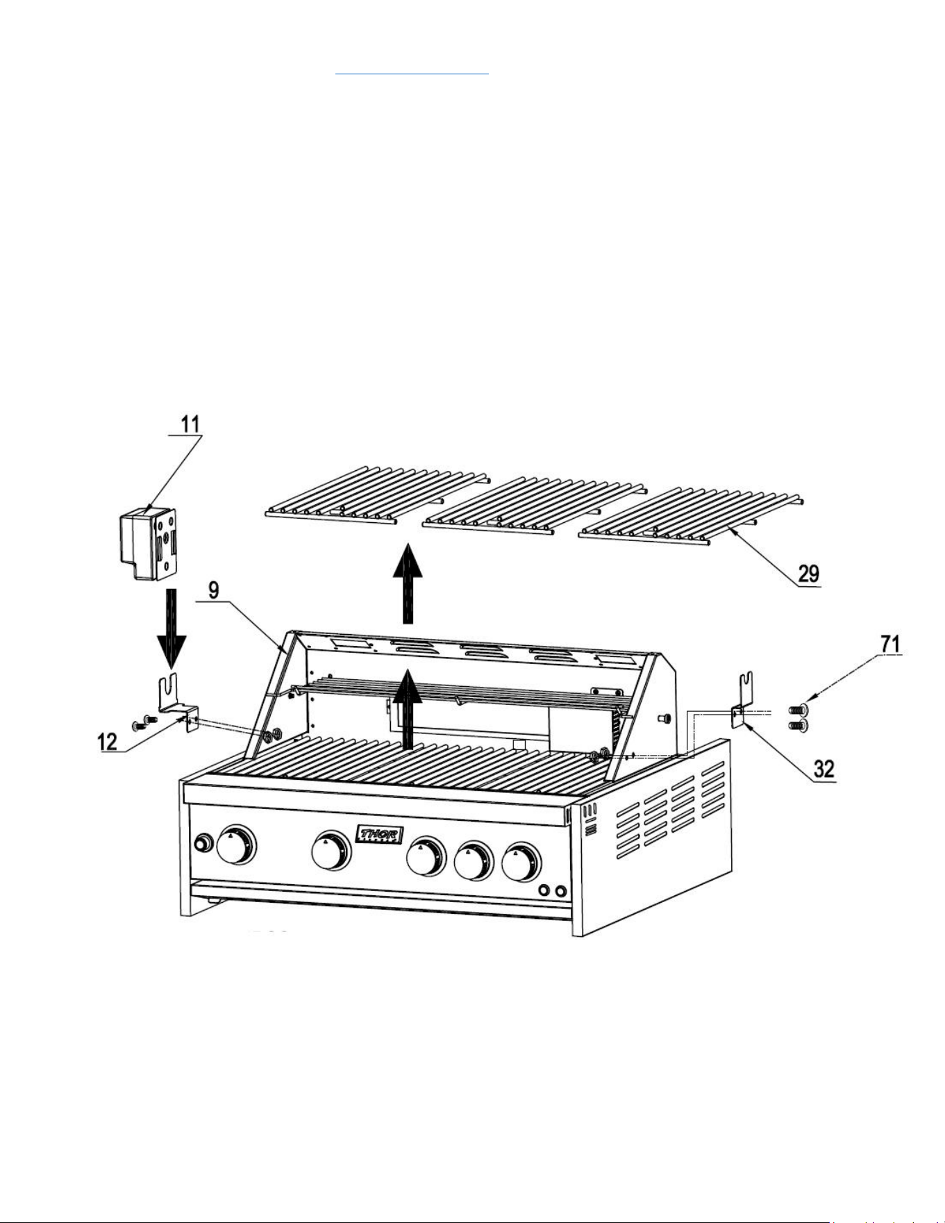
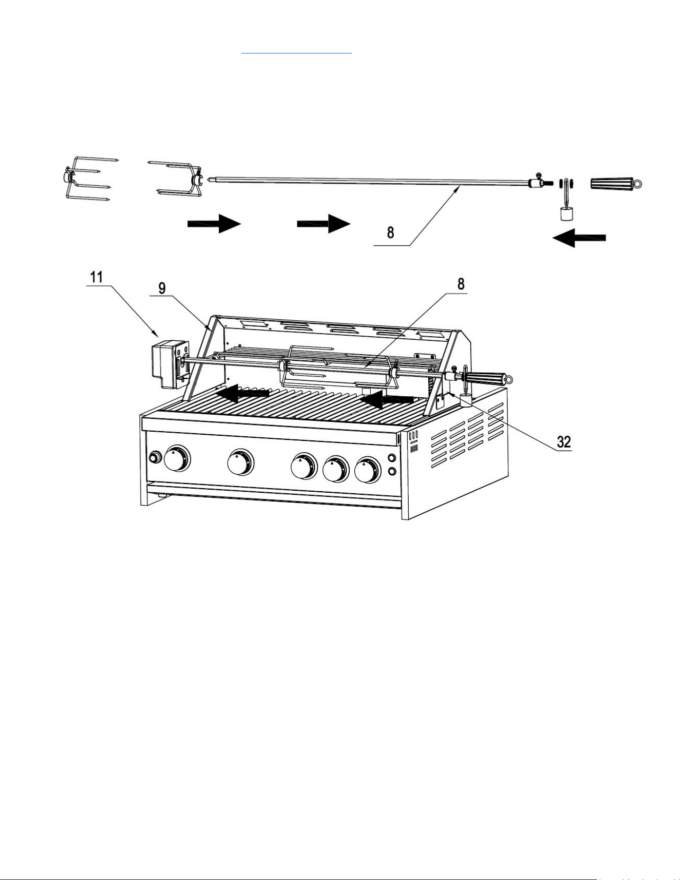
Outdoor Grill Installation
Step 1
1. Open the Grill cover. Remove All 3 pcs cooking racks (Part # 29) for the main burners to avoid
potential damage;
2. Use 2 pcs 1/4“*14 Philips thumb head screw (Part #71) with anti-slip design (Part #71) to install
motor holder (Part #12) to Grill cavity (Part #9);
3. Use 2 pcs 1/4“*14 Philips thumb head screw (Part #71) to install Rotisserie holder (Part #32) to Grill
cavity (Part #9);
4. Put Motor (Part #11) on top of motor support (Part #12) and put back 3 pcs cooking racks (Part #29)

service@thorgroup.us +1 877-288-8099
Welcome
Thank you for purchasing your Thor Kitchen Appliance! We appreciate
your business and we recommend that you read this entire User’s
Manual before operating your new appliance for the first time.
This manual contains instructions on how to properly install and set up
your new range, as well as insights into the unique features that our
product offers. Please keep this manual for future reference, as it
contains answers to questions that you might have as you begin to cook.
For any inquiries, please reach our customer service support at +1 877-
288-8099 at our business hours or email service@thorgroup.us.
Thank you,
Thor Group
This manual applies to the following models’ series:
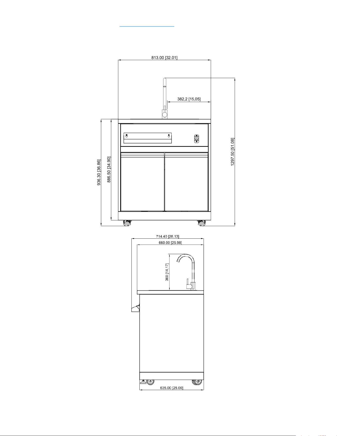
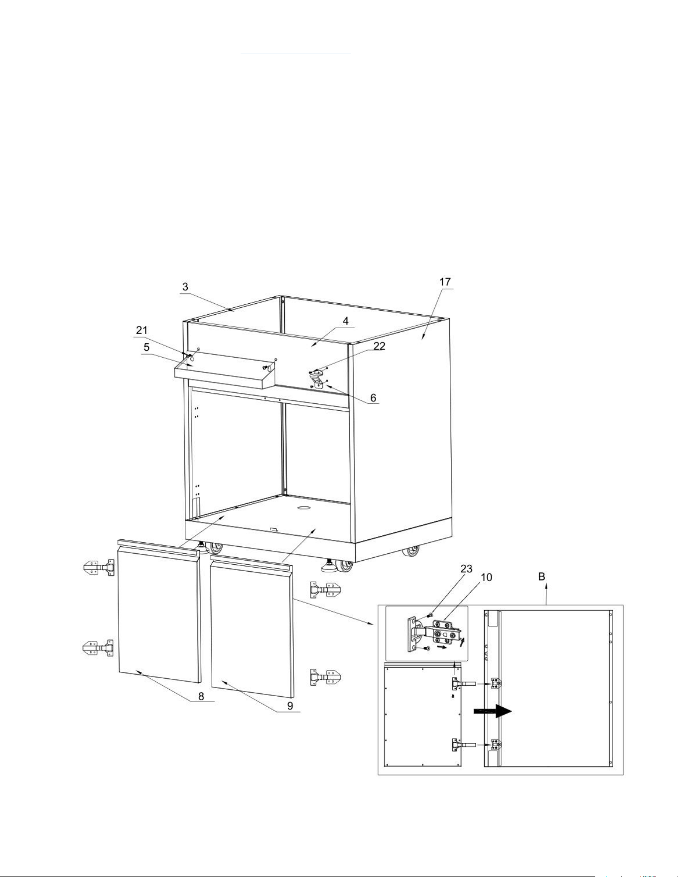
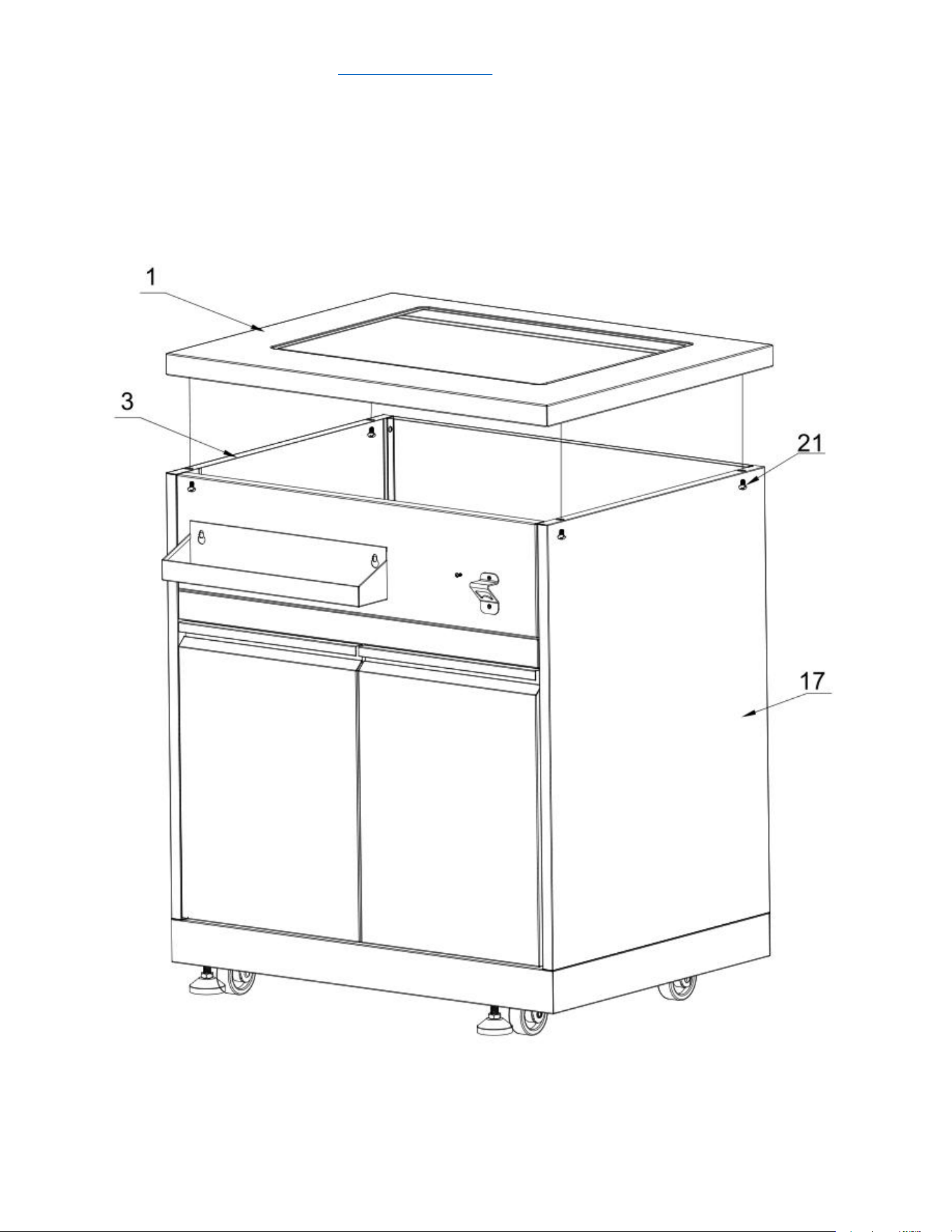
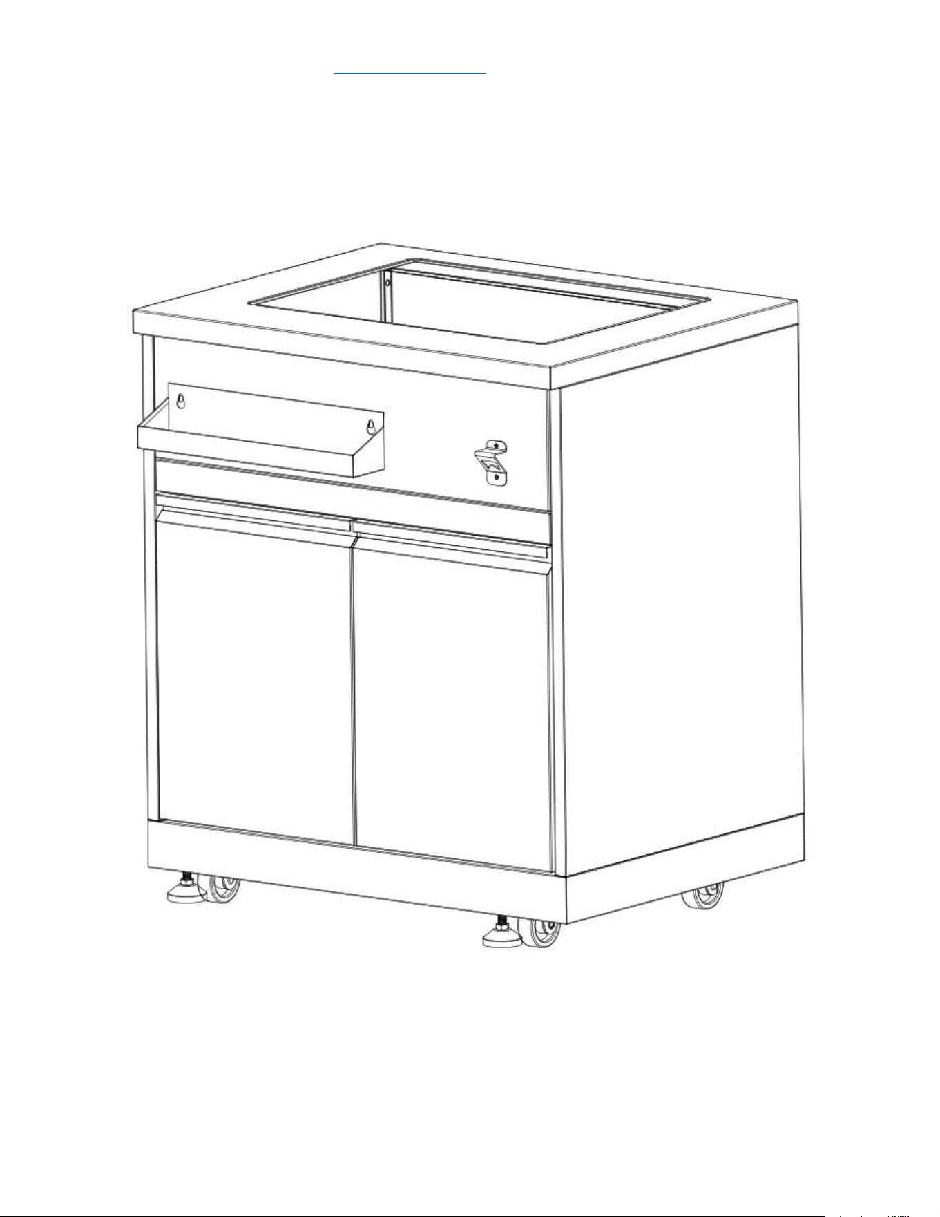
Model # MK01SS304 (Outdoor Sink Cabinet)

service@thorgroup.us +1 877-288-8099
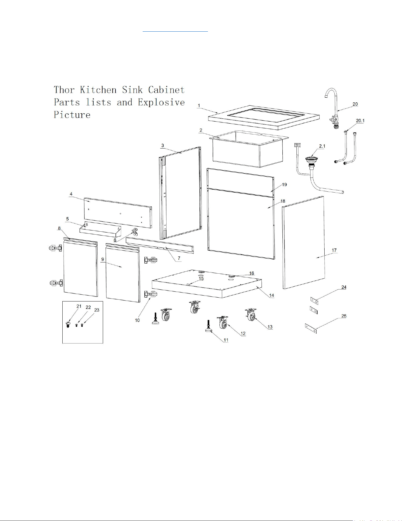
Parts List
If you are missing any part, please contact Thor Kitchen Customer Service
Department at 877-288-8099 at business hours, or email service@thorgroup.us
for help.
Explosive #
Part #
Part Name
Quantity
1
20.01.008067-000-A0
Countertop welding assembly
1
2
05.99.008008-000-A1
Water sink
1
2.1
05.19.008004-000-A0
Drainpipe with anti-overflow
1
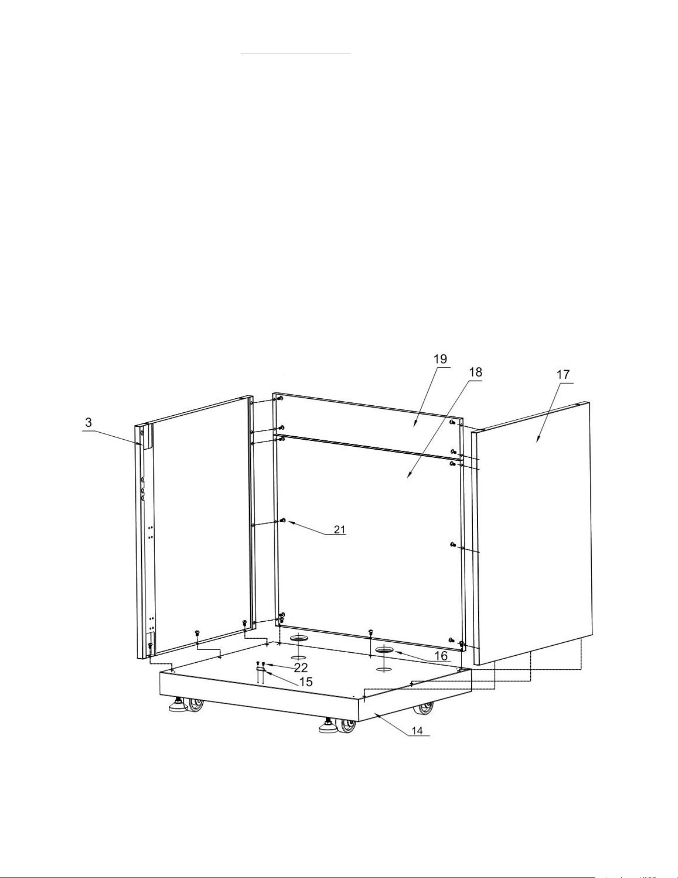
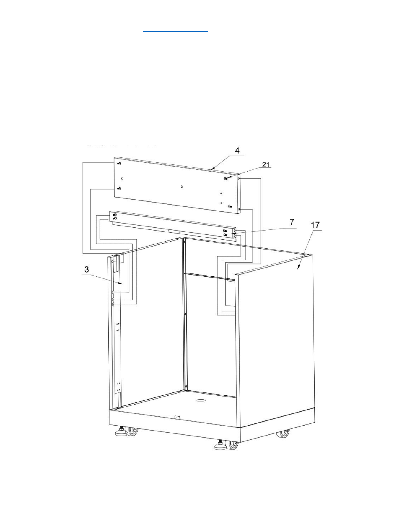
3
20.01.008089-000-A00
Left side panel welding assembly
1
4
20.01.001038-000-A0
Decoration panel welding assembly
1
5
20.01.001044-000-A0
Condiment holder welding
assembly
1
6
04.01.008033-000-A0
Bottle opener
1
7
20.01.001040-000-A1
Beam welding assembly
1
8
22.99.009182-000-A0
Left door welding assembly
1
9
22.99.009181-000-A0
Right door welding assembly
1
10
05.03.008001-000-A0
Door hinge
4
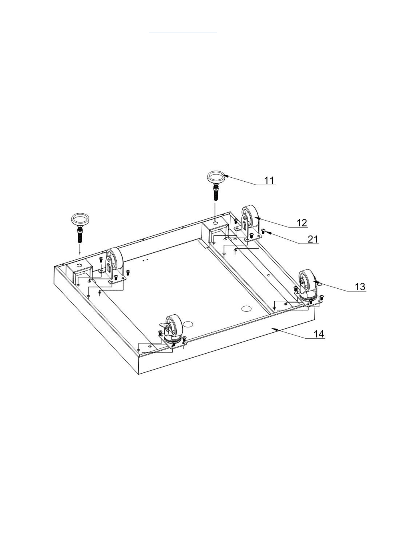
11
05.01.008004-000-A0
Supporting leg
2
12
05.10.000122-000-A0
Fixed caster
2
13
05.10.000123-000-A0
Universal caster with brake
2
14
20.01.008069-000-A0
Bottom panel welding assembly
1
15
04.01.002596-000-A1
Door barrier strip
1
16
06.08.008078-000-A0
Gasket
2
17
20.01.008088-000-A0
Right side panel welding assembly
1
18
20.01.001042-000-A0
Back panel welding assembly A
1
19
20.01.008091-000-A0
Back panel welding assembly B
1
20
05.99.008009-000-A0
Faucet
1
20.1
05.19.008005-000-A0
Faucet inlet pipe
2
21
06.02.000093-000-A0
¼” Philips thumb head screw with
anti-slip design
52
22
06.10.000042-000-A0
Philips thumb head screw
4
23
06.11.008056-000-A0
flat head screw
26
24
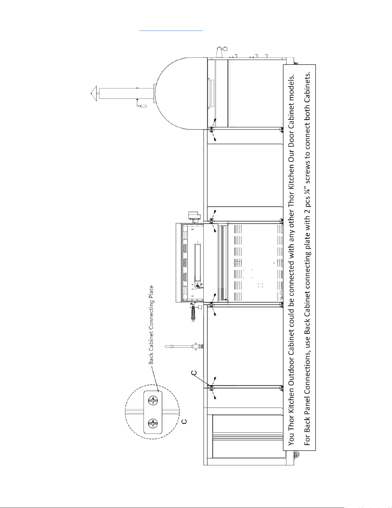
04.01.002580-000-A0
cabinet back connecting plate
2
25
04.01.002579-000-A0
cabinet front connecting plate
1
service@thorgroup.us +1 877-288-8099
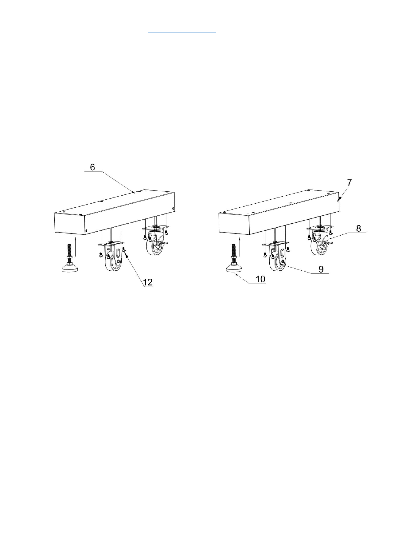
Cabinet Installation
Step 1
1. Connect 2 pcs supporting leg (Part # 11) to bottom welding part, and
tighten two legs;
2. Connect 2 pcs Fixed caster (Part # 12) and 2 pcs universal caster with brake
(Part # 13) with 16 pcs ¼” Philips thumb head screw with anti-slip design
(Part # 21) to bottom welding part (Part # 14)
service@thorgroup.us +1 877-288-8099
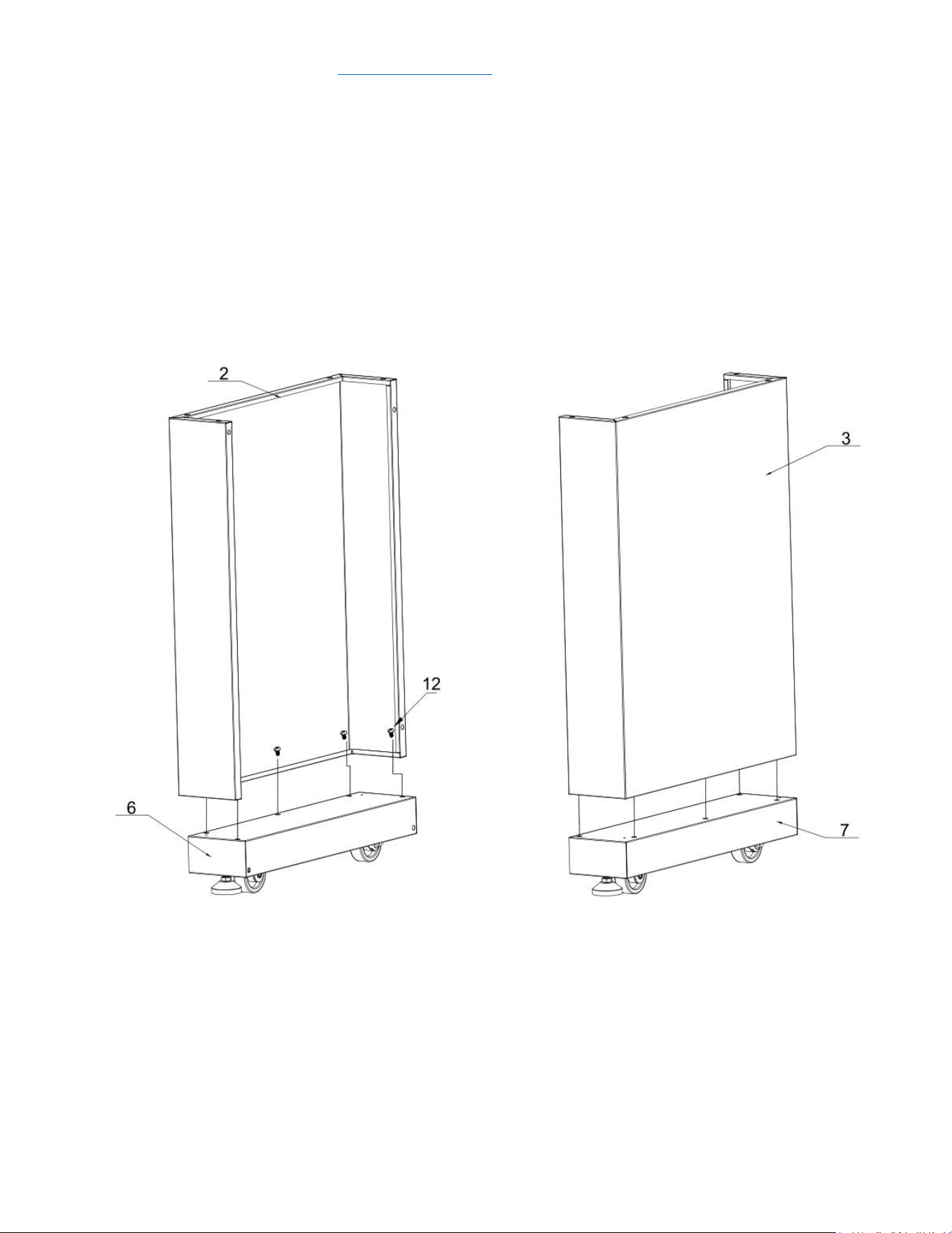
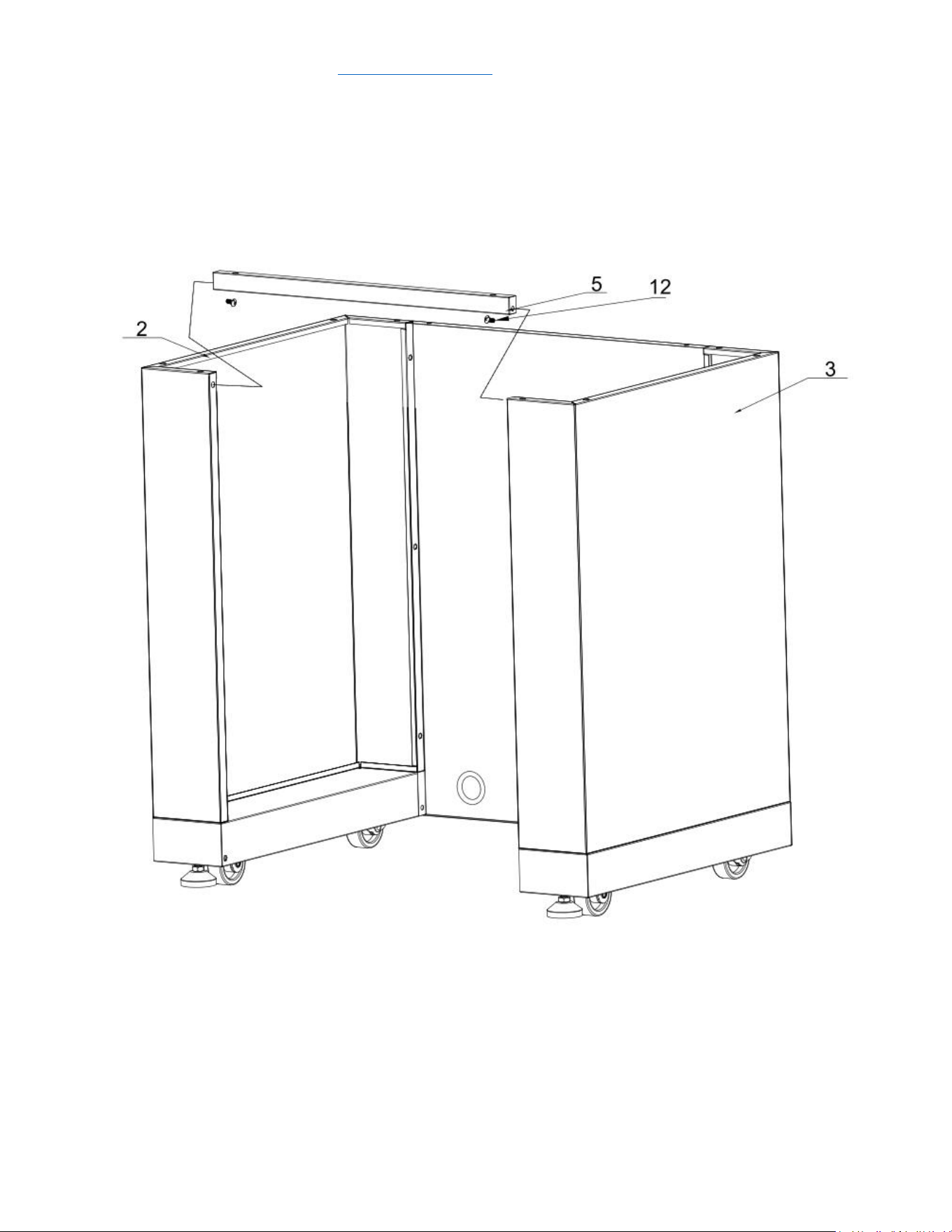
Step 2
1. Reverse back Bottom panel welding assembly (Part # 14). Install 2 pcs
Gasket (Part # 16) to Part # 14, and then use 2 pcs Philips thumb head
screw (Part # 22) to install Door barrier strip (Part # 15) to Part # 14;
2. Use 3 pcs ¼” Philips thumb head screw with anti-slip design (Part # 21) to
tighten Left side panel welding assembly (Part # 3) to Part # 14;
3. Use 3 pcs Part # 21 to tighten Right side panel welding assembly (Part # 17)
to Part #14;
4. Use 13 pcs Part # 21 to tighten Back panel welding assembly A (Part # 18)
and Back panel welding assembly B (Part # 19) with Part #13, #3 and #17.
5. Do not over-tighten all the screws until parts are lined up.
6.
service@thorgroup.us +1 877-288-8099
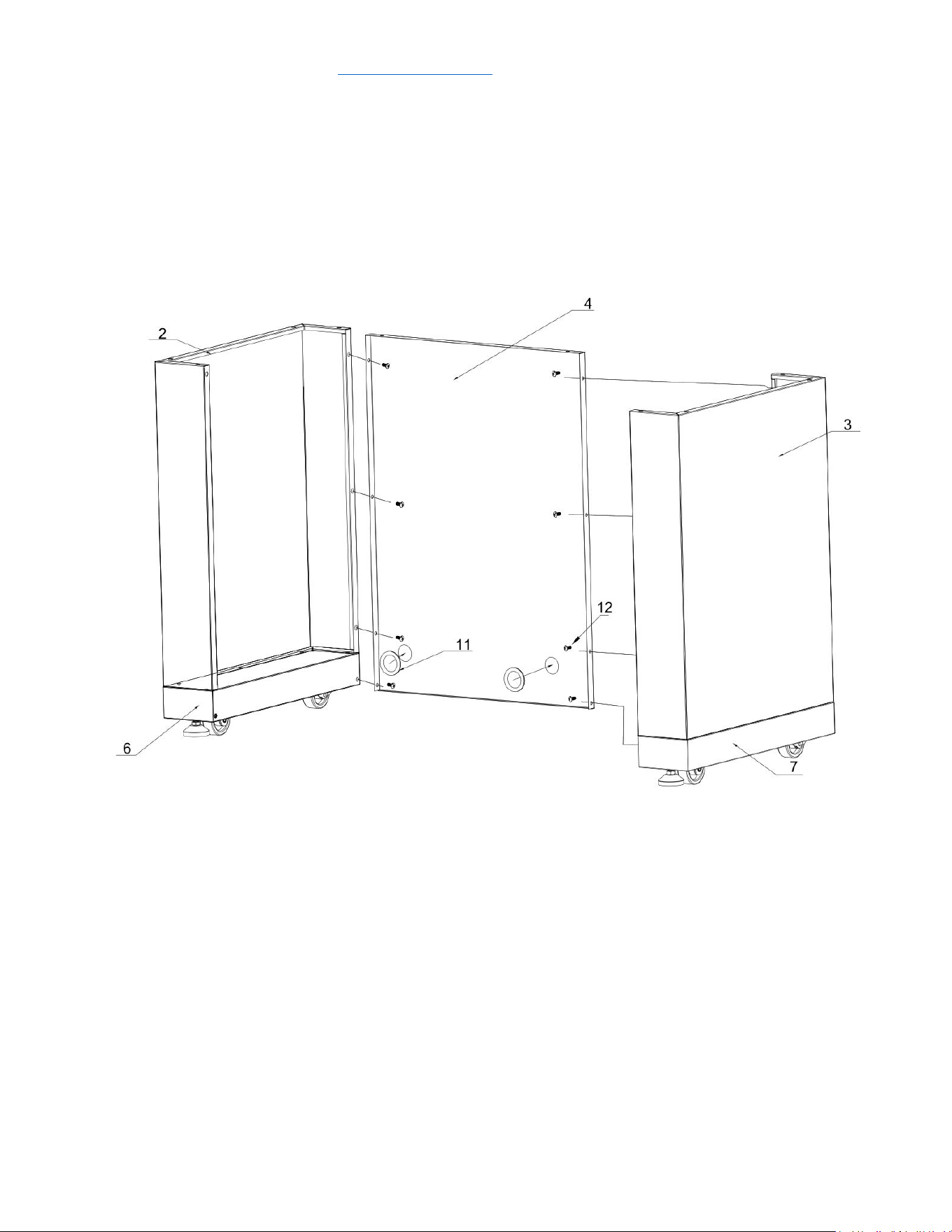
Step 4
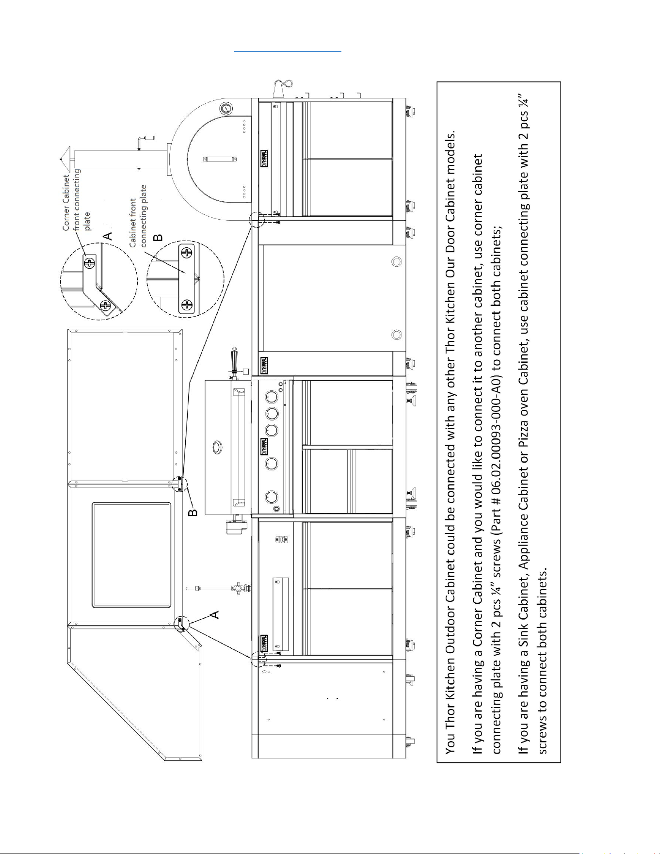
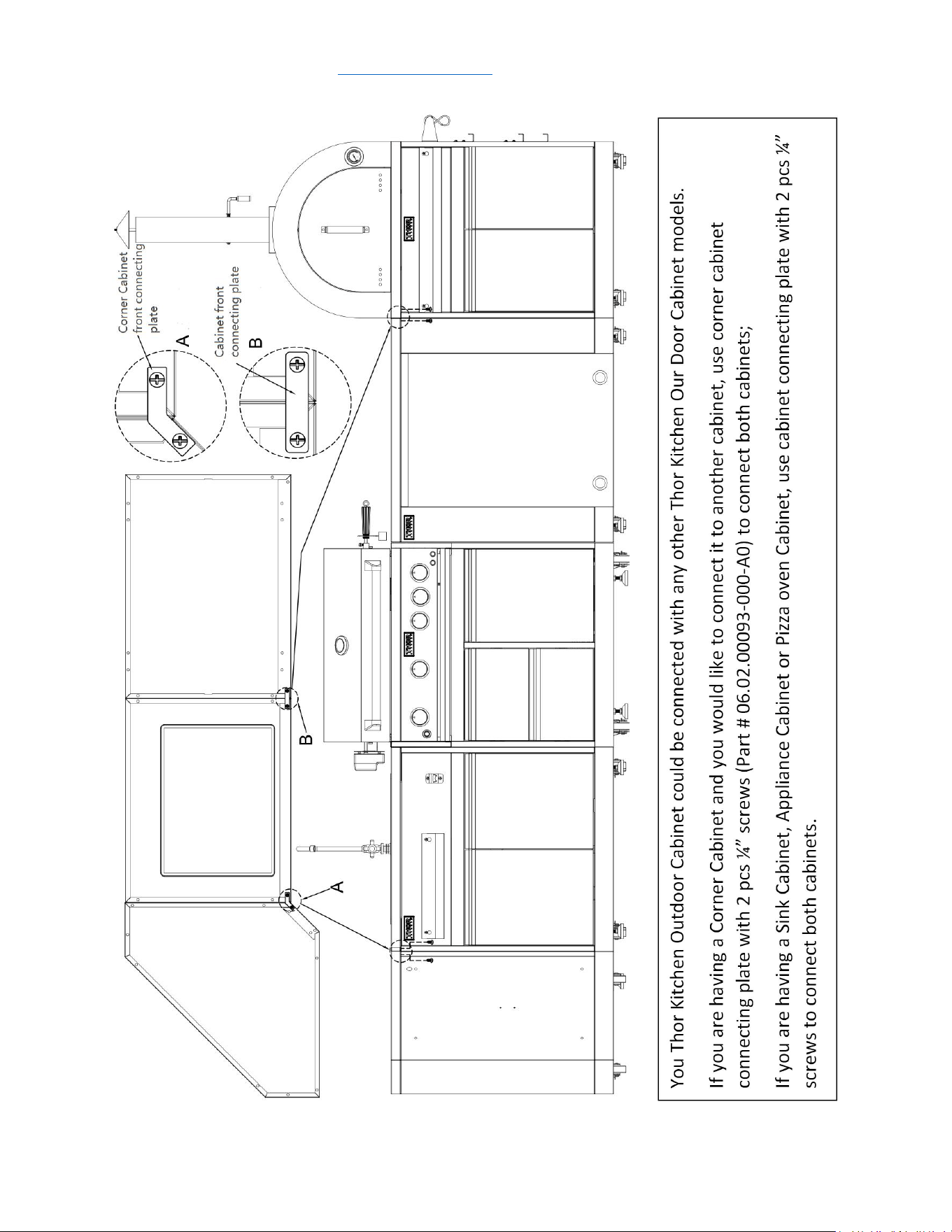
1. Use 2 pcs Part # 21 to connect Condiment holder welding assembly (Part # 5) with Part
#4;
2. Use 2 pcs Philips thumb head screw (Part # 22) to connect bottle opener (Part # 6) with
Part #4;
3. Use 24 pcs flat head screw (Part # 23, Showing in Picture “B”) to install 4 pcs Door hinge
with Part # 3, Left door welding assembly (Part # 8), Right door welding assembly (Part #
9) and Right-side panel welding assembly (Part # 17).
4. Install Part # 8 to Part # 3 and install Part # 9 to Part # 17. Do not over-tighten all the
screws until parts are lined up.
service@thorgroup.us +1 877-288-8099
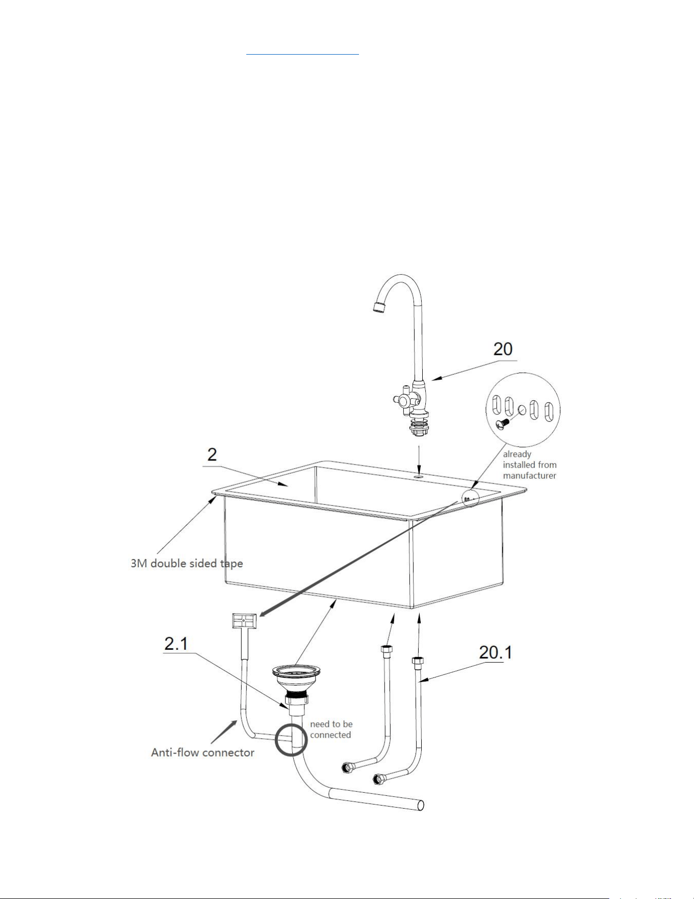
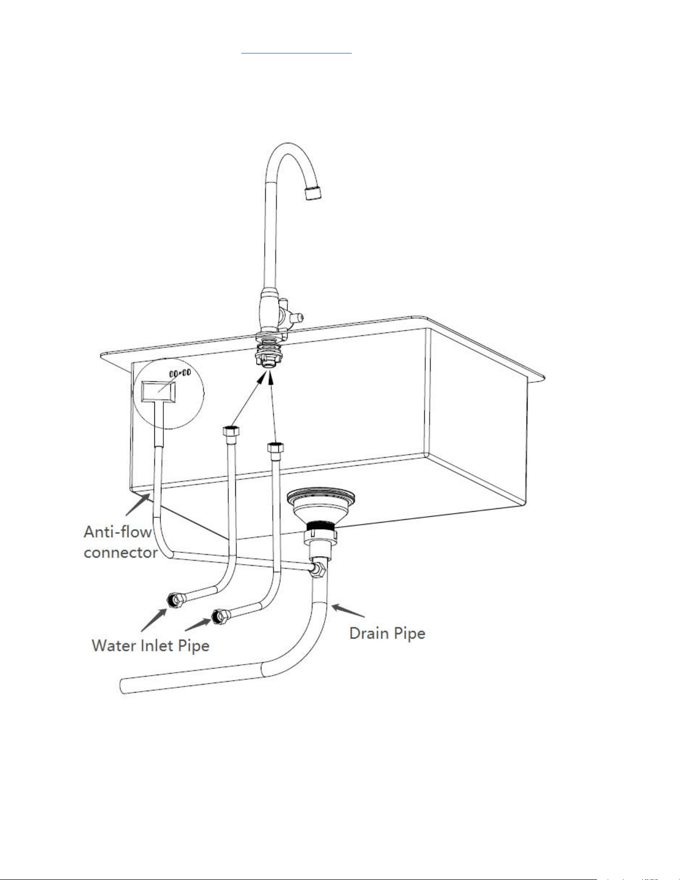
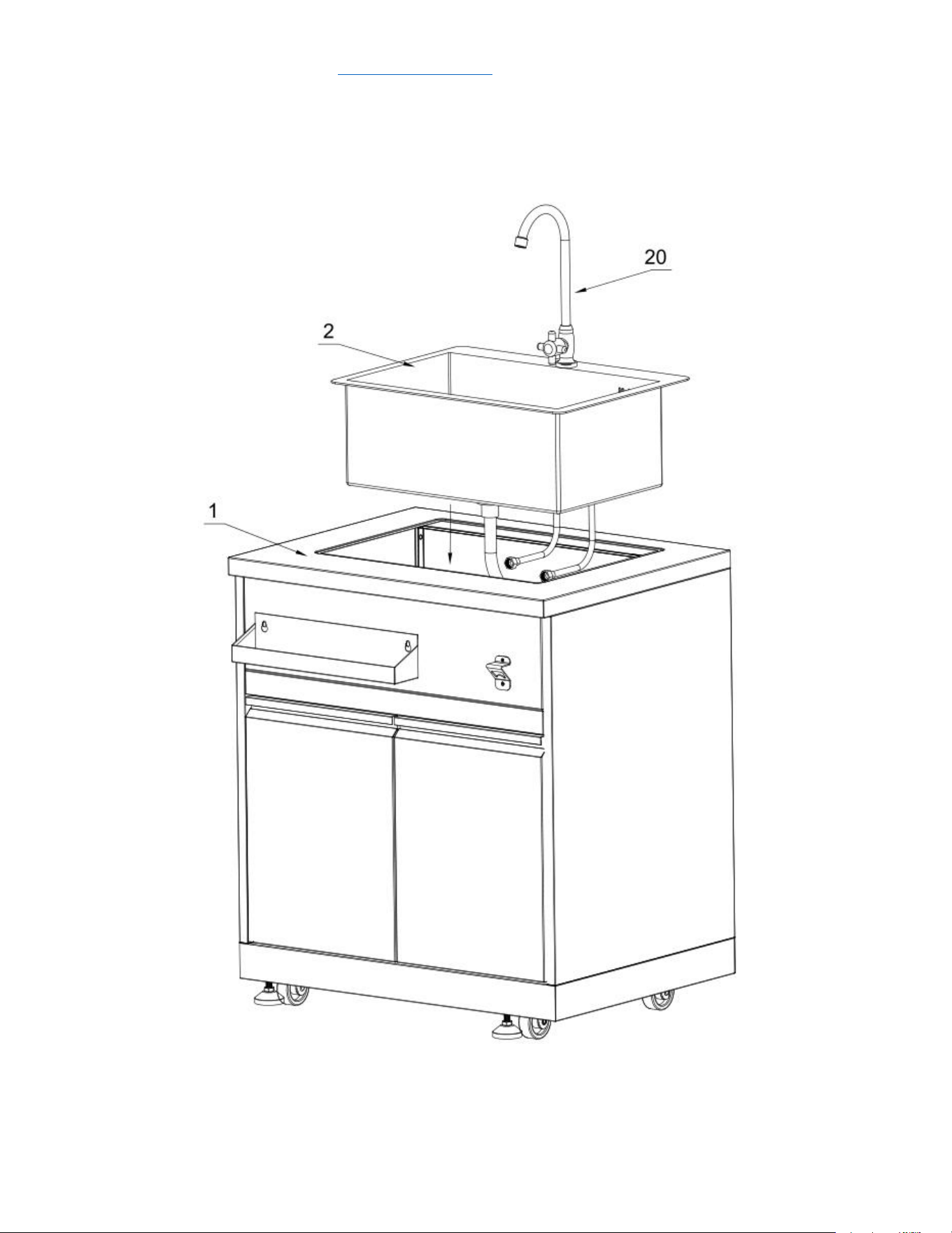
Step 7
1. Install Faucet (Part # 20) to Water sink (Part # 2), then put 2 pcs water inlet
pipe (part of # 18) into the bottom of Part # 20;
2. Put Drain pipe with anti-overflow (Part # 2.1) to the bottom of Part # 2,
then use specialized screw 3/16” screw within Part # 2.1 to lock Anti-
overflow connector (already installed from the manufacturer), connect
anti-flow connector to the side of drain pipe;
3. Take out 3M double sided tape from the edge of the water sink.


service@thorgroup.us +1 877-288-8099
Welcome
Thank you for purchasing your Thor Kitchen Appliance! We appreciate
your business and we recommend that you read this entire User’s
Manual before operating your new appliance for the first time.
This manual contains instructions on how to properly install and set up
your new range, as well as insights into the unique features that our
product offers. Please keep this manual for future reference, as it
contains answers to questions that you might have as you begin to cook.
For any inquiries, please reach our customer service support at +1 877-
288-8099 at our business hours or email service@thorgroup.us.
Thank you,
Thor Group
This manual applies to the following models’ series:
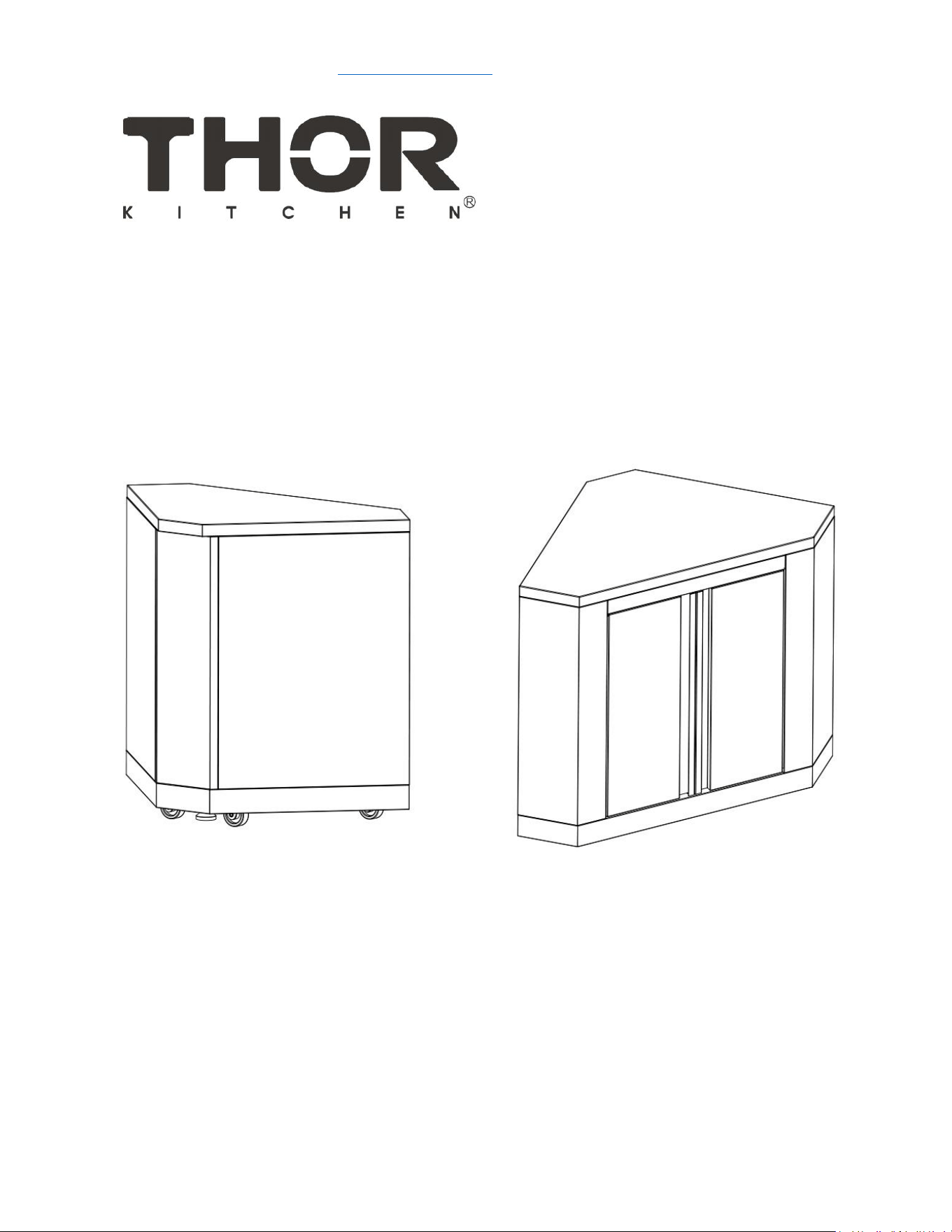
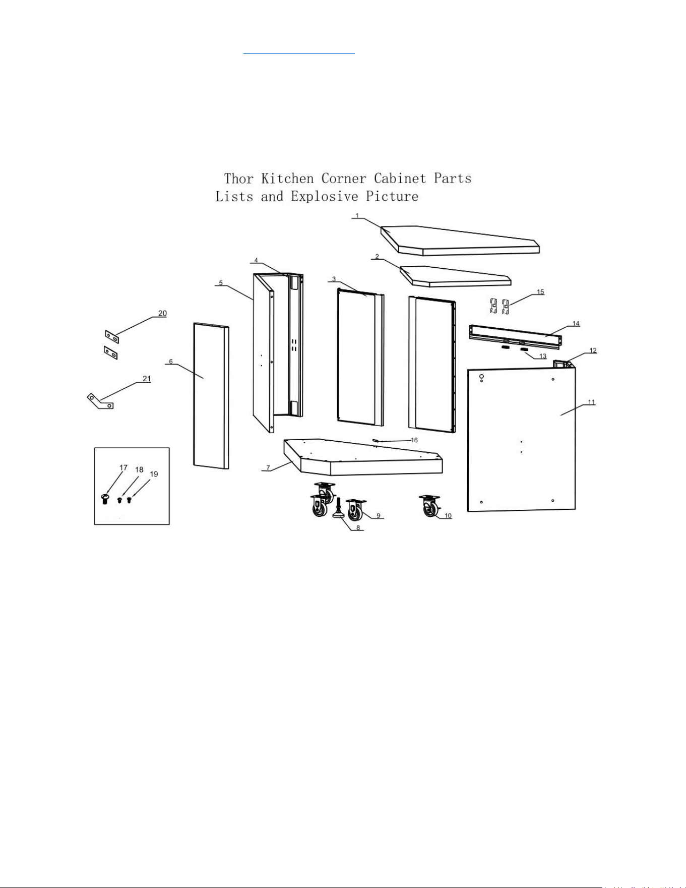
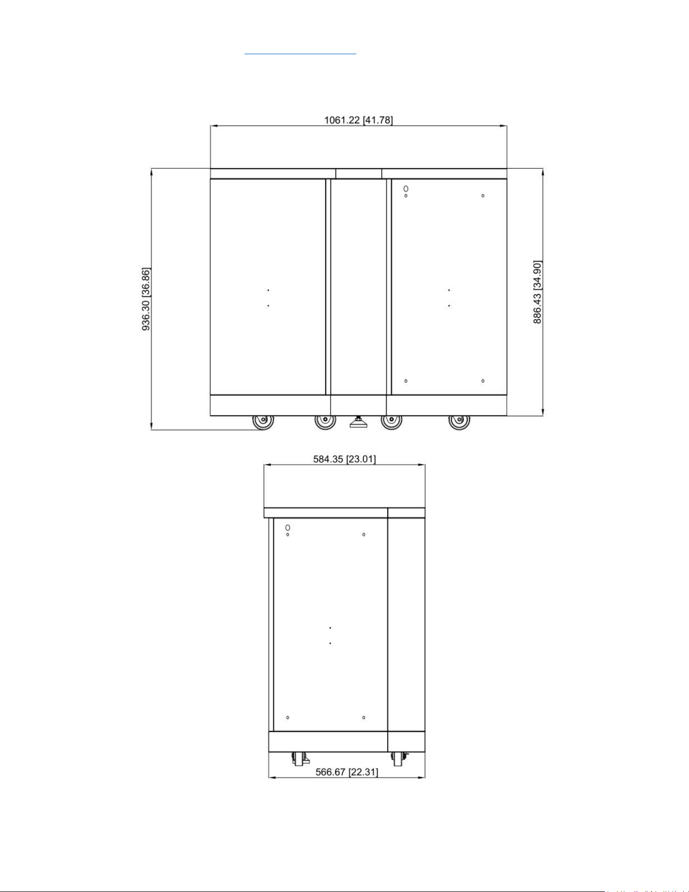
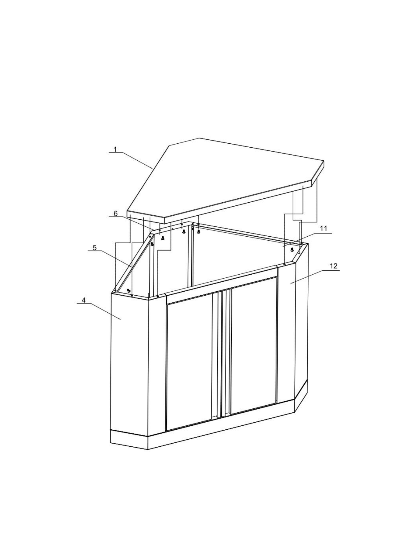
Model # MK06SS304 (Outdoor Corner Cabinet)

service@thorgroup.us +1 877-288-8099
Parts List
If you are missing any part, please contact Thor Kitchen Customer Service
Department at 877-288-8099 at business hours, or email service@thorgroup.us
for help.
Explosive
#
Part #
Part Name
Quantity
1
20.01.008054-000-A0
Countertop welding assembly
1
2
20.01.001063-000-A0
Laminate welding assembly
1
3
22.99.009228-000-A0
Door welding assembly
2
4
20.01.001059-000-A0
Left side panel A welding assembly
1
5
20.01.001060-000-A0
Left side panel B welding assembly
1
6
20.01.001064-000-A0
Front panel welding assembly
1
7
20.01.008077-000-A0
Bottom panel welding assembly
1
8
05.01.008004-000-A0
Supporting leg
2
9
05.10.000122-000-A0
Fixed caster
2
10
05.10.000123-000-A0
Universal caster
2
11
20.01.001062-000-A0
Right side panel B welding assembly
1
12
20.01.001061-000-A0
Left side panel A welding assembly
1
13
05.12.008009-000-A0
Door magnetic
2
14
20.05.008086-000-A0
Beam welding assembly
1
15
04.04.008570-000-A0
Laminate welding holder
2
16
04.01.002596-000-A1
Door barrier strip
1
17
06.02.000093-000-A0
¼” Philips thumb head screw with
anti-slip design
58
18
06.10.000042-000-A0
Philips thumb head screw
2
19
06.11.008056-000-A0
flat head screw
16
20
04.01.002580-000-A0
cabinet back connecting plate
2
21
04.01.002640-000-A0
corner cabinet front connecting
plate
1
service@thorgroup.us +1 877-288-8099
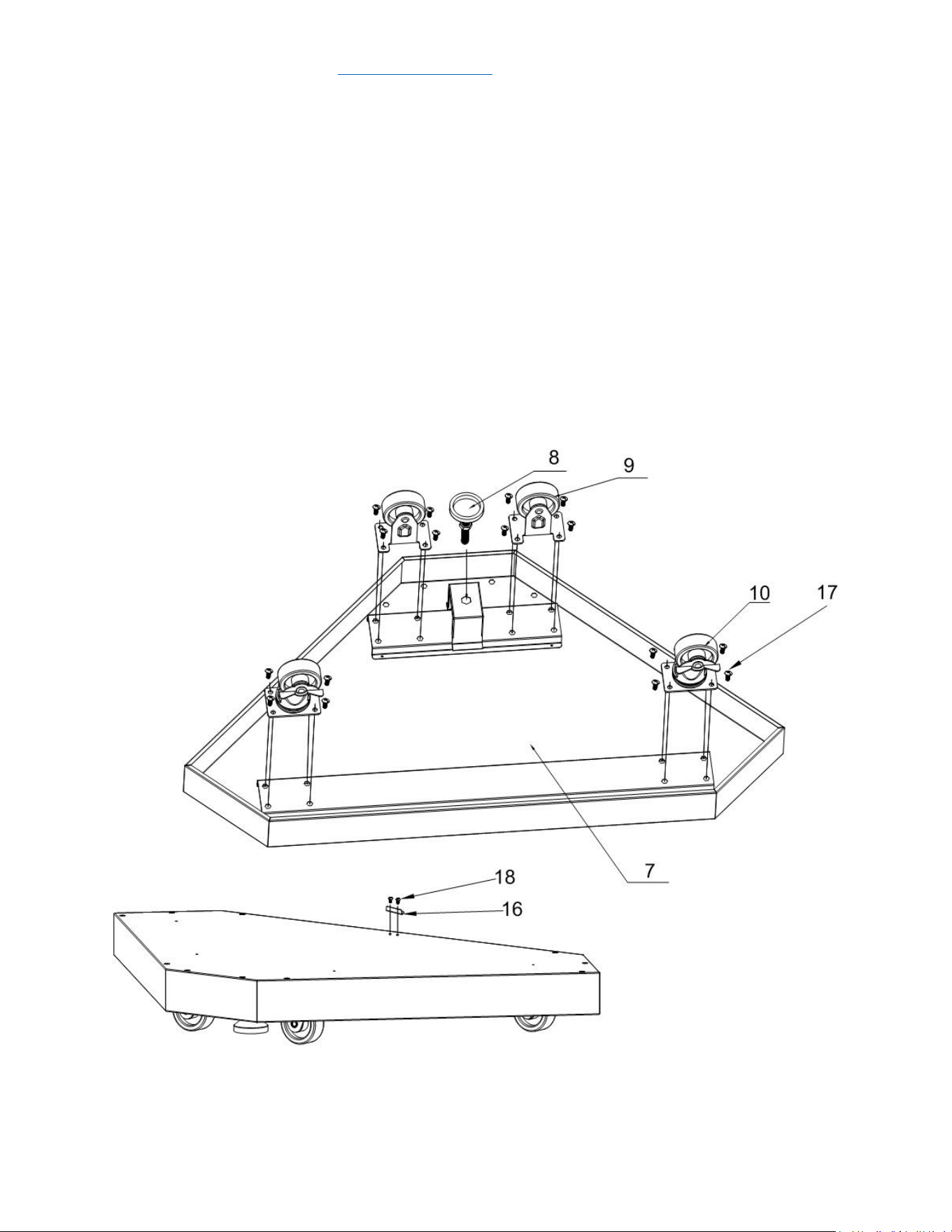
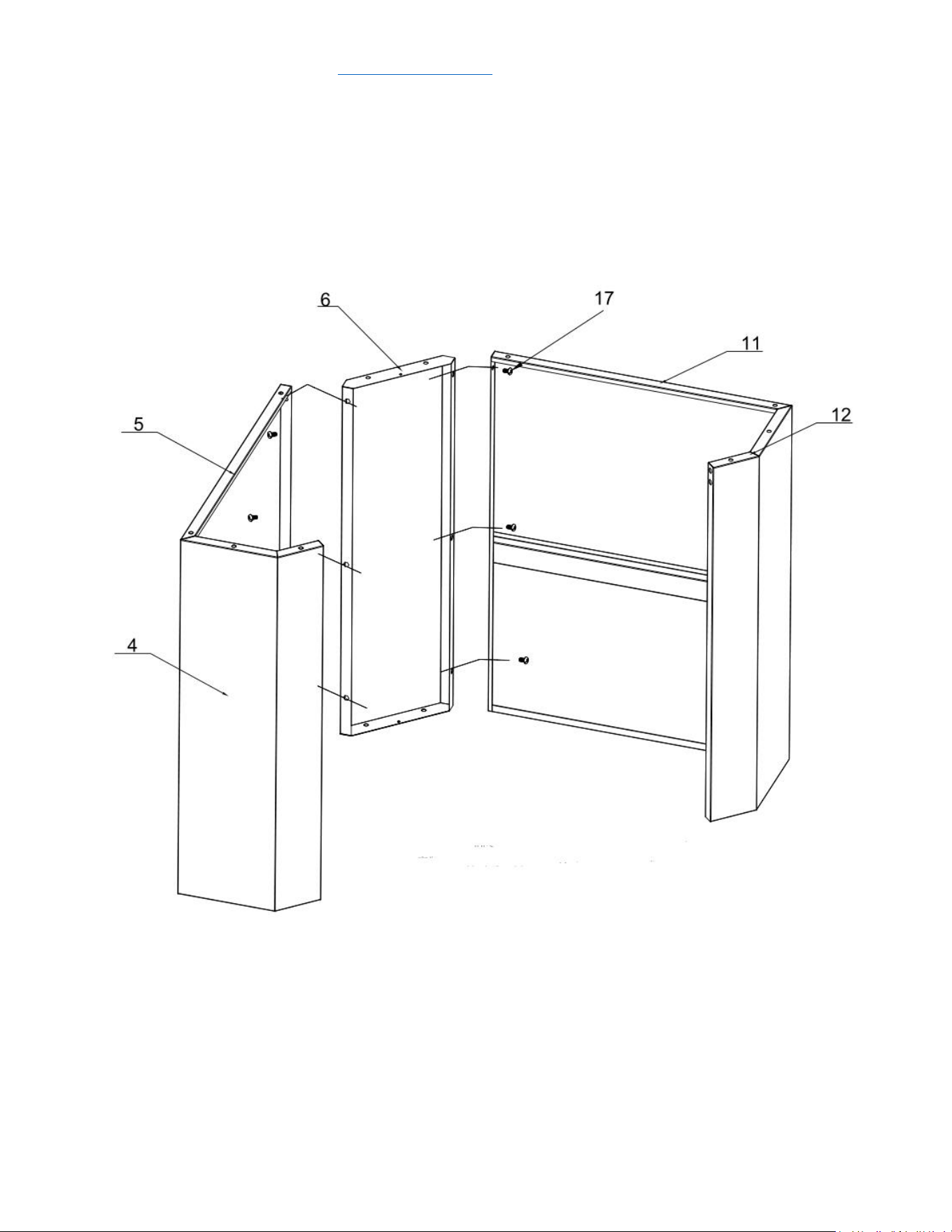
Cabinet Installation
Step 1
1. Reverse the bottom welding part (Part # 7) and put 1 pc supporting leg
(Part # 8) to Part # 7. Use hand to adjust the leg to the suitable position;
2. Use 16 pcs ¼” flat Philip’s head screw (Part #17) to connect 2 pcs fixed
casters (Part # 9) and 2 pcs universal casters with brake (Part # 10) to Part
#7;
3. Reverse Part # 7 and use 2 pcs Philips thumb head screw (Part # 18) to
install Door barrier strip (Part # 18) to Part # 7.
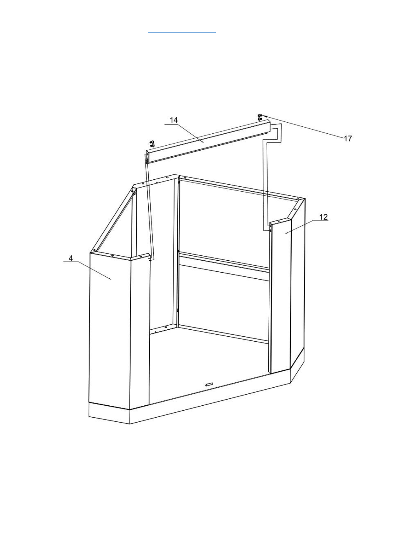
service@thorgroup.us +1 877-288-8099
Step 2
1. Use 3 pcs ¼” flat Philip’s head screw (Part # 17) to connect left side panel A
(Part # 4) to Part # 5;
2. Use 3 pcs ¼” flat Philip’s head screw (Part # 17) to connect right side panel
a (Part # 12) to Part # 11;
3. Do not over-tighten all the screws until parts are lined up.
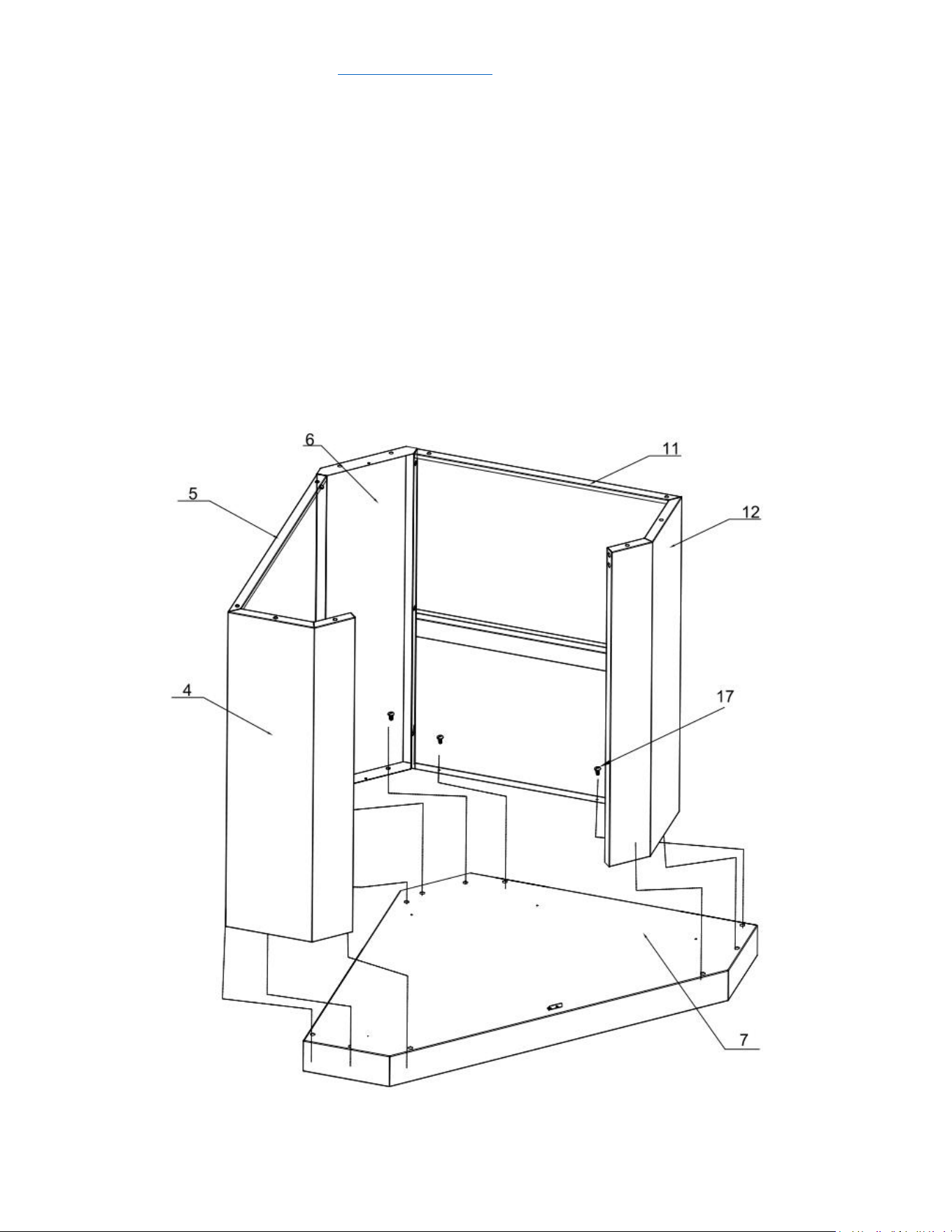
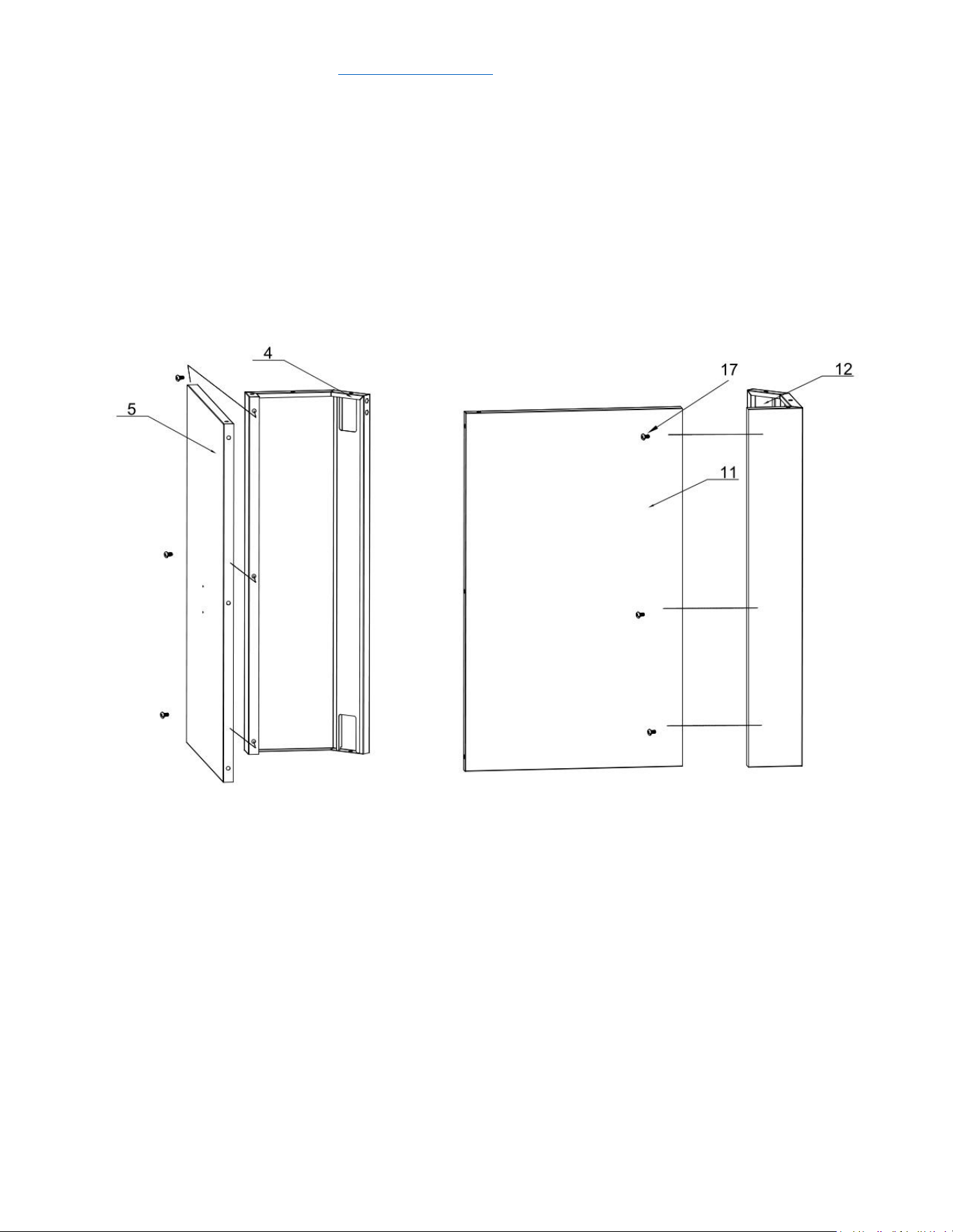
service@thorgroup.us +1 877-288-8099
Step 4
1. Use 4 pcs Philips thumb head screw with anti-slip design (Part # 17) to
connect Left side panel A welding assembly (Part # 4) and Left side panel B
welding assembly (Part # 5) to Bottom panel welding assembly (Part # 7);
2. Use 4 pcs Part # 17 to connect Right side panel B welding assembly (Part #
11) and Left side panel A welding assembly (Part # 12) to Part # 7;
3. Use 2 pcs Part 17 to connect Front panel welding assembly (Part # 6) to Part
# 7.
4. Do not over-tighten all the screws until parts are lined up.
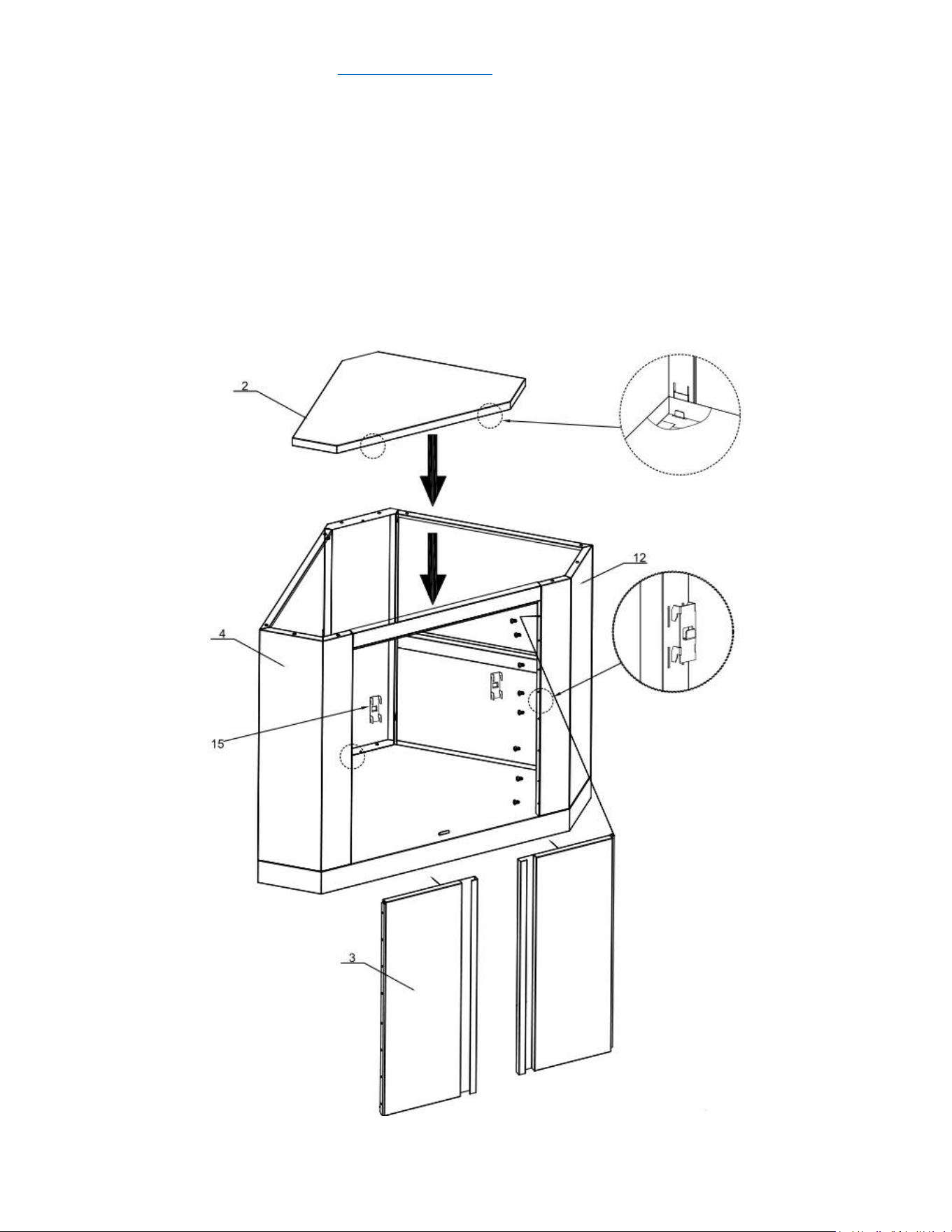
service@thorgroup.us +1 877-288-8099
Step 6
1. Install 2 pcs Laminate welding holder (Part # 15) to Part # 4 and Part # 12,
and then install Laminate welding assembly (Part # 2) on the top;
2. Use 16 pcs flat head screw (Part # 19) to install Door welding assembly (Part
# 3) to Part # 4 and Part # 12.
3. Do not over-tighten all the screws until parts are lined up.


service@thorgroup.us +1 877-288-8099
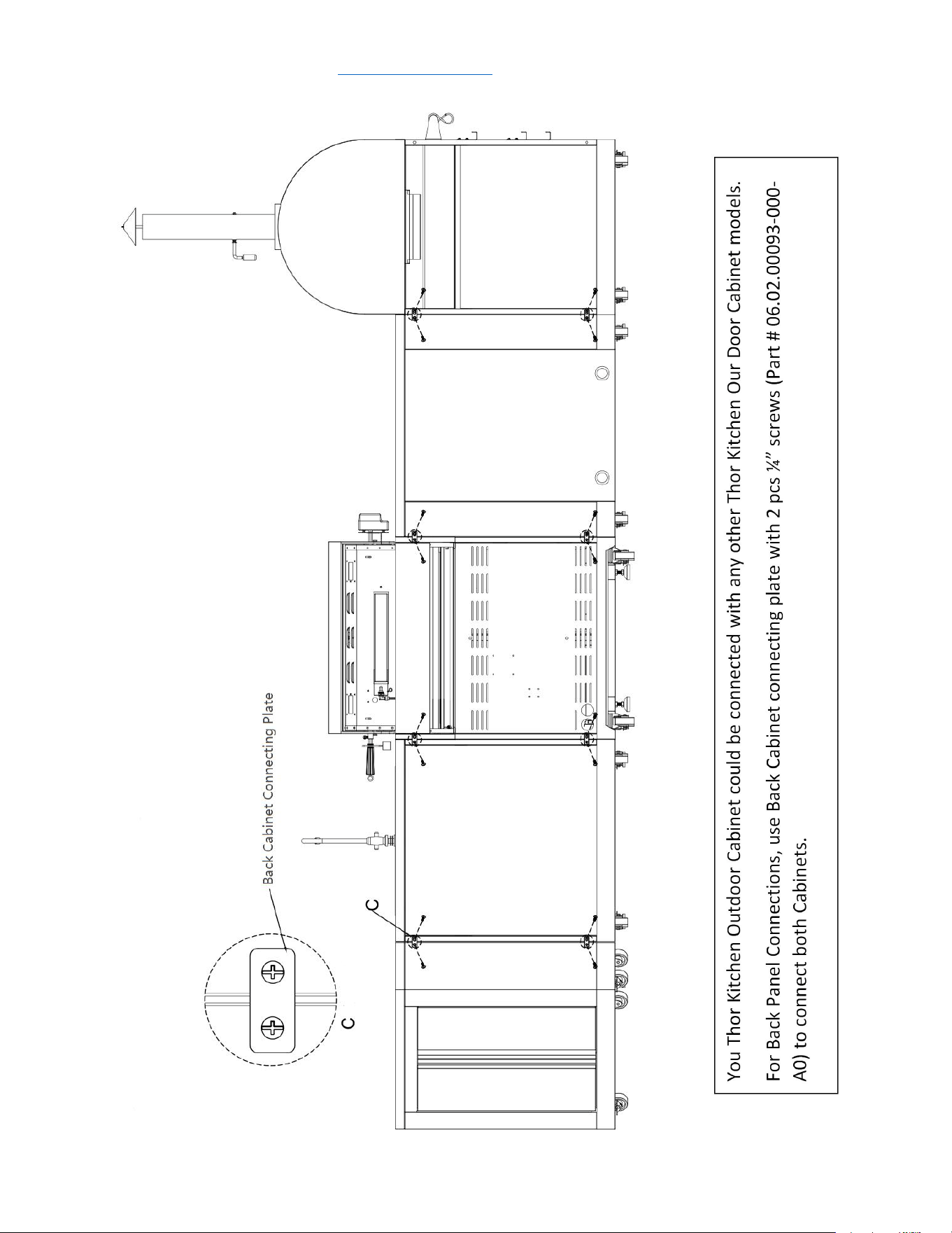
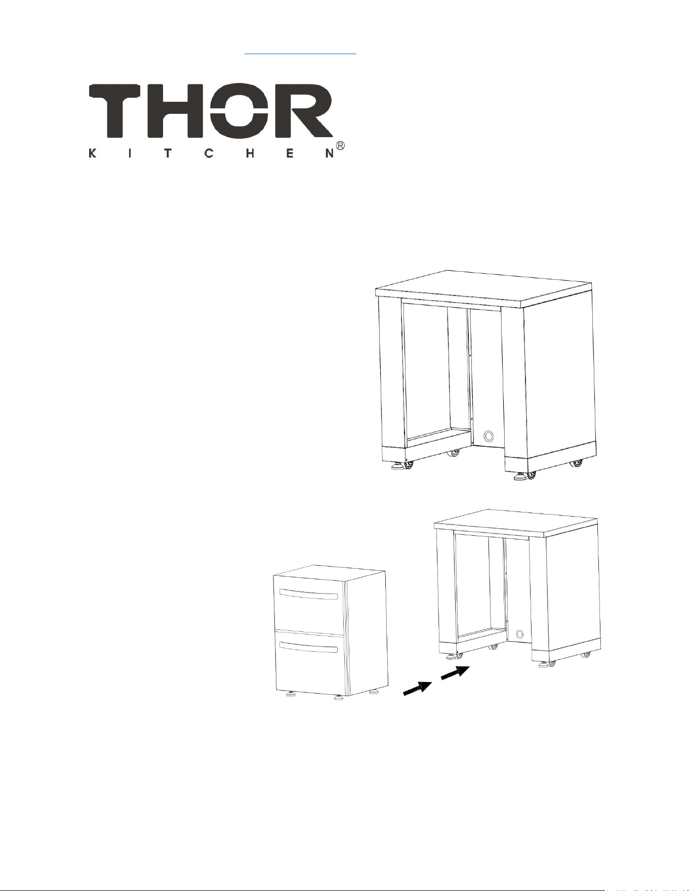
THOR KITCHEN OUTDOOR Appliance Cabinet Installation Manual
MODEL# MK02SS304 (Appliance Not included)
IMPORTANT:
Save for electrical inspector’s use.
Installer: Leave installation instructions with the homeowner.
Homeowner: Keep installation instructions for future reference

service@thorgroup.us +1 877-288-8099
Welcome
Thank you for purchasing your Thor Kitchen Appliance! We appreciate
your business and we recommend that you read this entire User’s
Manual before operating your new appliance for the first time.
This manual contains instructions on how to properly install and set up
your new range, as well as insights into the unique features that our
product offers. Please keep this manual for future reference, as it
contains answers to questions that you might have as you begin to cook.
For any inquiries, please reach our customer service support at +1 877-
288-8099 at our business hours or email service@thorgroup.us.
Thank you,
Thor Group
This manual applies to the following models’ series:
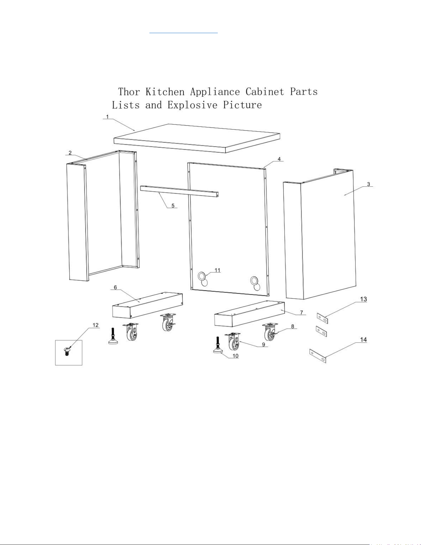
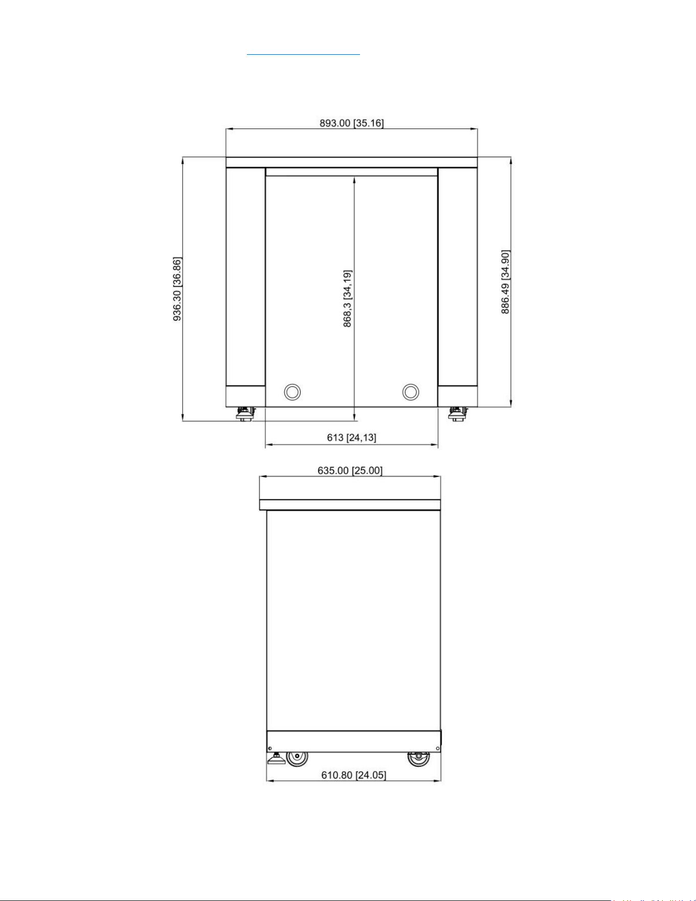
Model # MK02SS304 (Outdoor Appliance Cabinet)
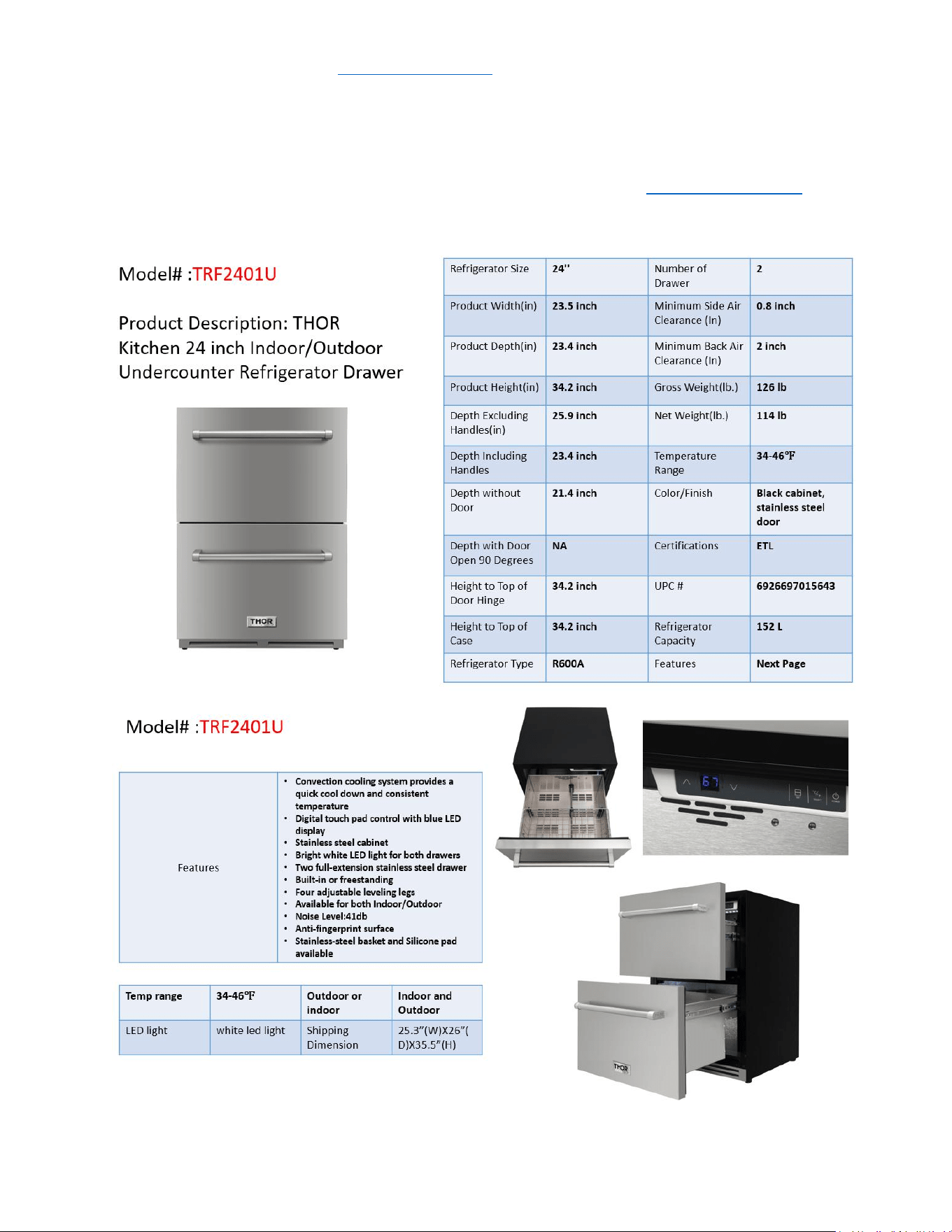
Model # TRF2401U (Outdoor Two-drawer under cabinet refrigerator)
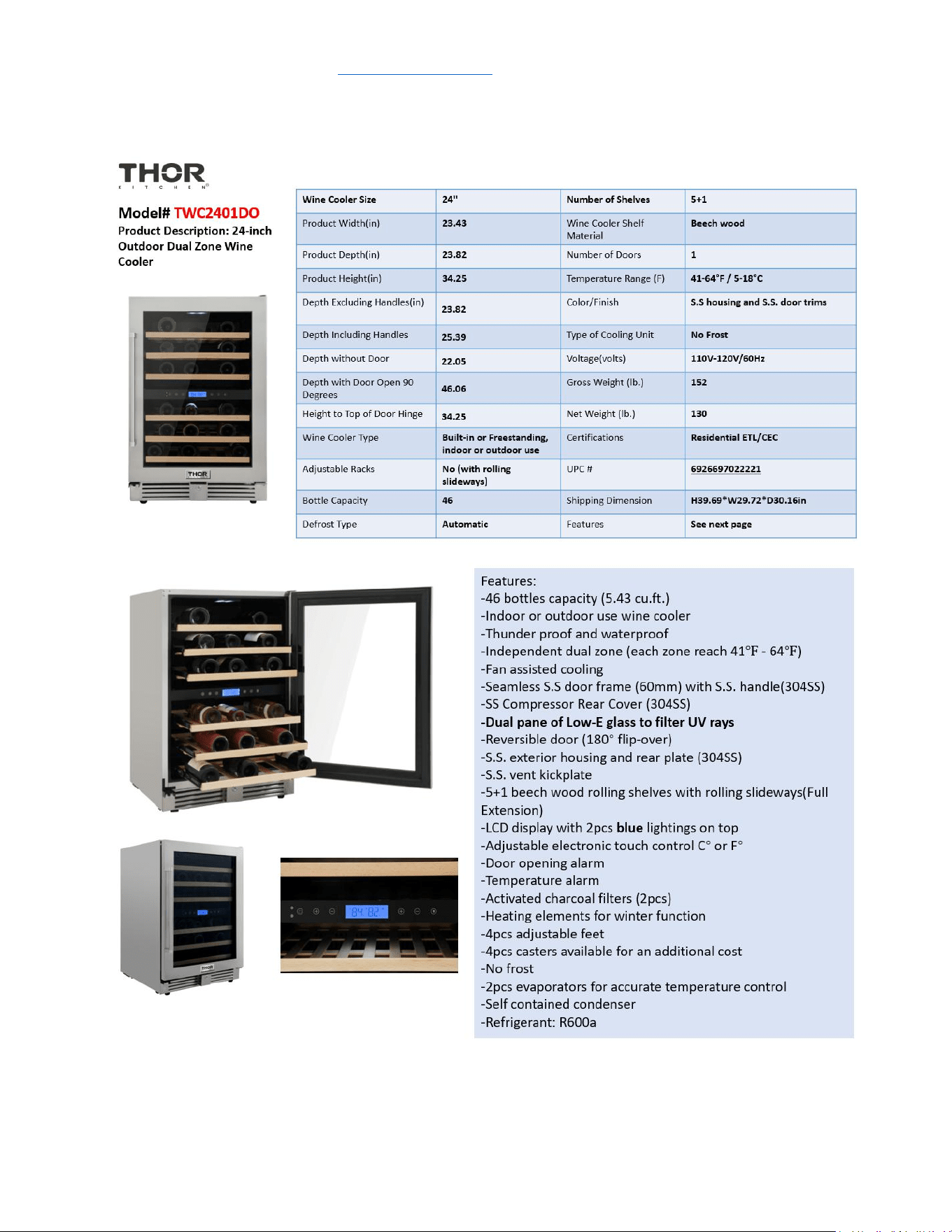
Model # TWC2401DO (Outdoor Wine Cooler)

service@thorgroup.us +1 877-288-8099
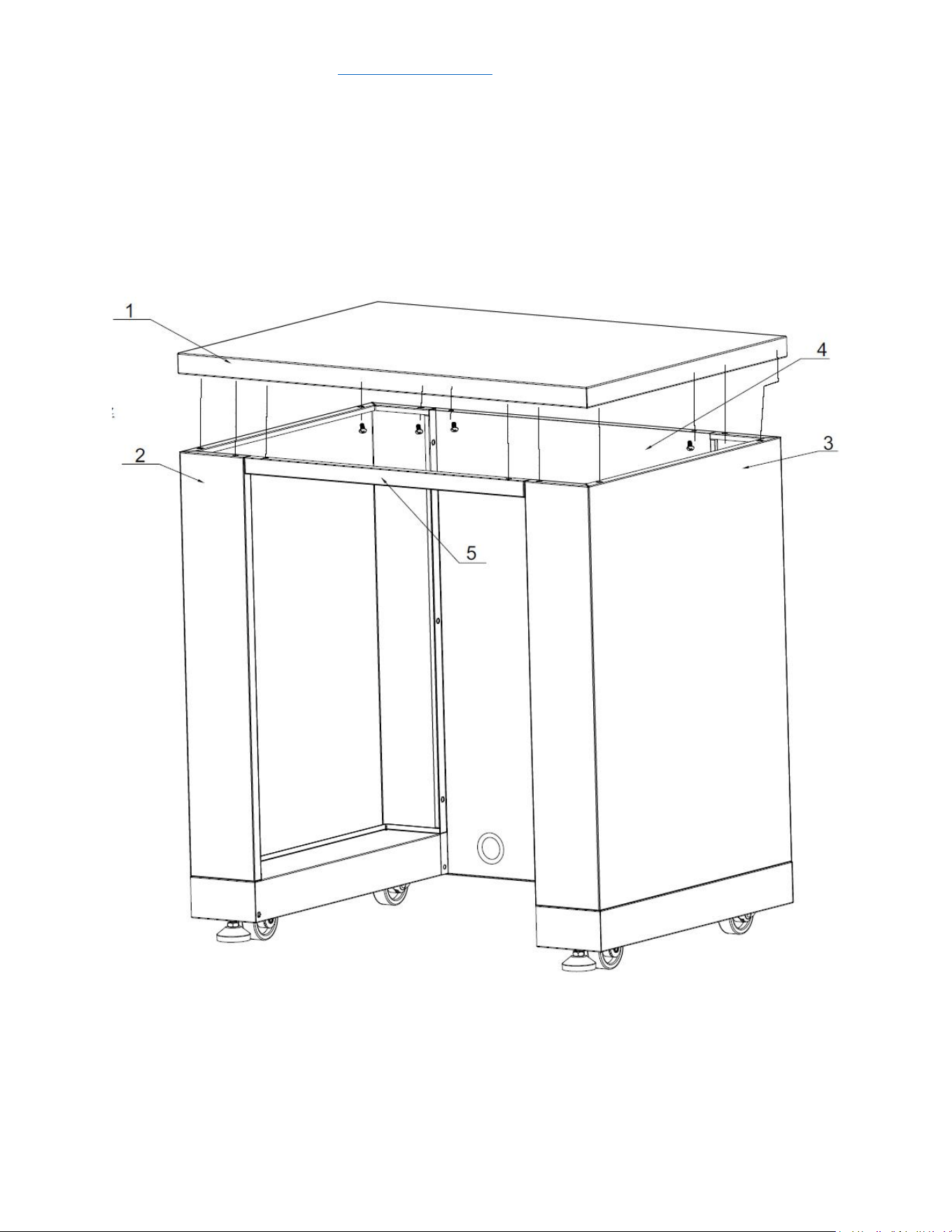
Parts List
If you are missing any part, please contact Thor Kitchen Customer Service Department at 877-
288-8099 at business hours, or email service@thorgroup.us for help.
Explosive #
Part #
Part Name
Quantity
1
20.01.008041-000-A0
Countertop welding assembly
1
2
20.01.001030-000-A0
Left side panel welding assembly
1
3
20.01.001031-000-A0
Right side panel welding assembly
1
4
20.01.001032-000-A0
Back panel welding assembly
1
5
20.01.001033-000-A0
Beam welding assembly
1
6
20.01.008042-000-A0
Right bottom panel welding assembly
1
7
20.01.008043-000-A0
Left bottom panel welding assembly
1
8
05.10.000123-000-A0
Universal caster with brake
2
9
05.10.000122-000-A0
Fixed caster
2
10
05.01.008004-000-A0
Supporting leg
2
11
06.08.008078-000-A0
Rubber gasket
2
12
06.02.000093-000-A0
Philips thumb head screw with anti-slip design
56
13
04.01.002580-000-A0
cabinet back connecting plate
2
14
04.01.002579-000-A0
cabinet front connecting plate
1
service@thorgroup.us +1 877-288-8099
Cabinet Installation
Step 1
1. Install 2 pcs Supporting Leg (Part # 10) to bottom right welding assembly (Part # 6) and
bottom left welding assembly (Part # 7). Use hand to adjust the supporting leg to the
suitable position;
2. Use 16 pcs ¼” flat Philip’s head screw (Part # 12) to connect 2 pcs fixed caster (Part # 9)
and 2 pcs universal casters (Part # 8) to Part #6 and #7.
service@thorgroup.us +1 877-288-8099
Step 2
1. Use 5 pcs ¼” flat Philip’s head screws (part # 12) to connect left side panel (Part # 2) to
Part #6;
2. Use 5 pcs ¼” flat Philip’s head screws (part # 12) to connect right side panel (Part # 3) to
Part #7;
3. Do not over-tighten all the screws until parts are lined up.
service@thorgroup.us +1 877-288-8099
Step 3
1. Install 2 pcs rubber gaskets (Part # 11) to Back Panel (Part # 4);
2. Use 4 pcs ¼” flat Philip’s head screws (Part # 12) to connect Part #4 to Part #2 and #6;
3. Use 4 pcs ¼” flat Philip’s head screws (Part # 12) to connect Part #4 to Part #3 and #7;
4. Do not over-tighten all the screws until parts are lined up.


service@thorgroup.us +1 877-288-8099
Welcome
Thank you for purchasing your Thor Kitchen Appliance! We appreciate
your business and we recommend that you read this entire User’s
Manual before operating your new appliance for the first time.
This manual contains instructions on how to properly install and set up
your new range, as well as insights into the unique features that our
product offers. Please keep this manual for future reference, as it
contains answers to questions that you might have as you begin to cook.
For any inquiries, please reach our customer service support at +1 877-
288-8099 at our business hours or email service@thorgroup.us.
Thank you,
Thor Group
This manual applies to the following models’ series:
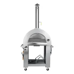
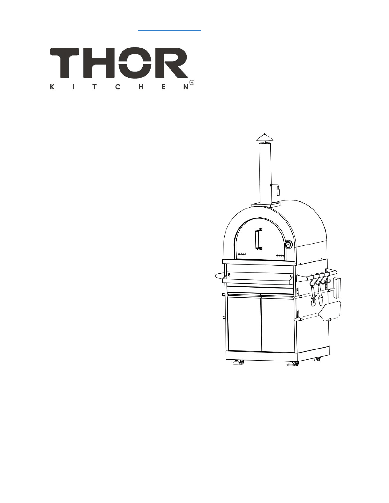
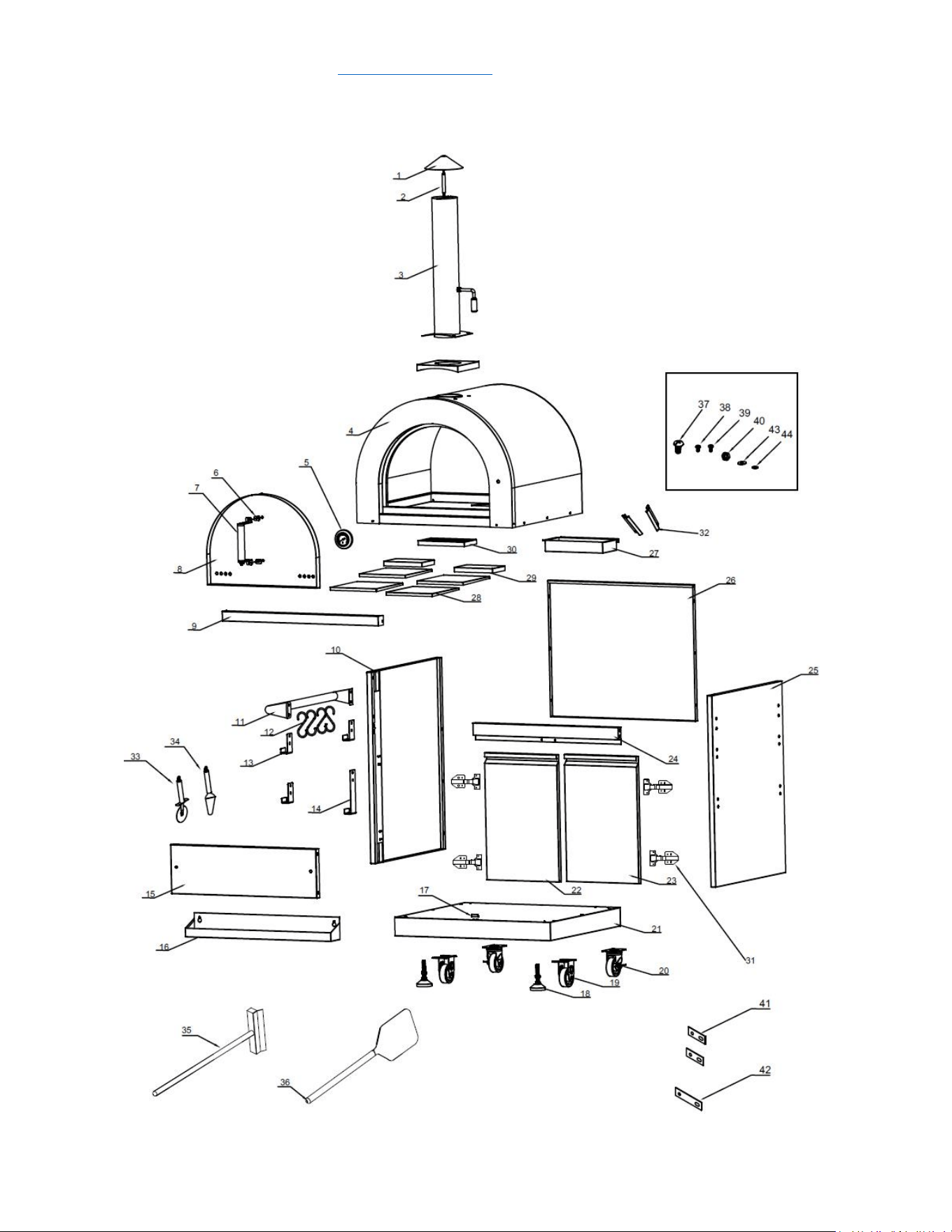
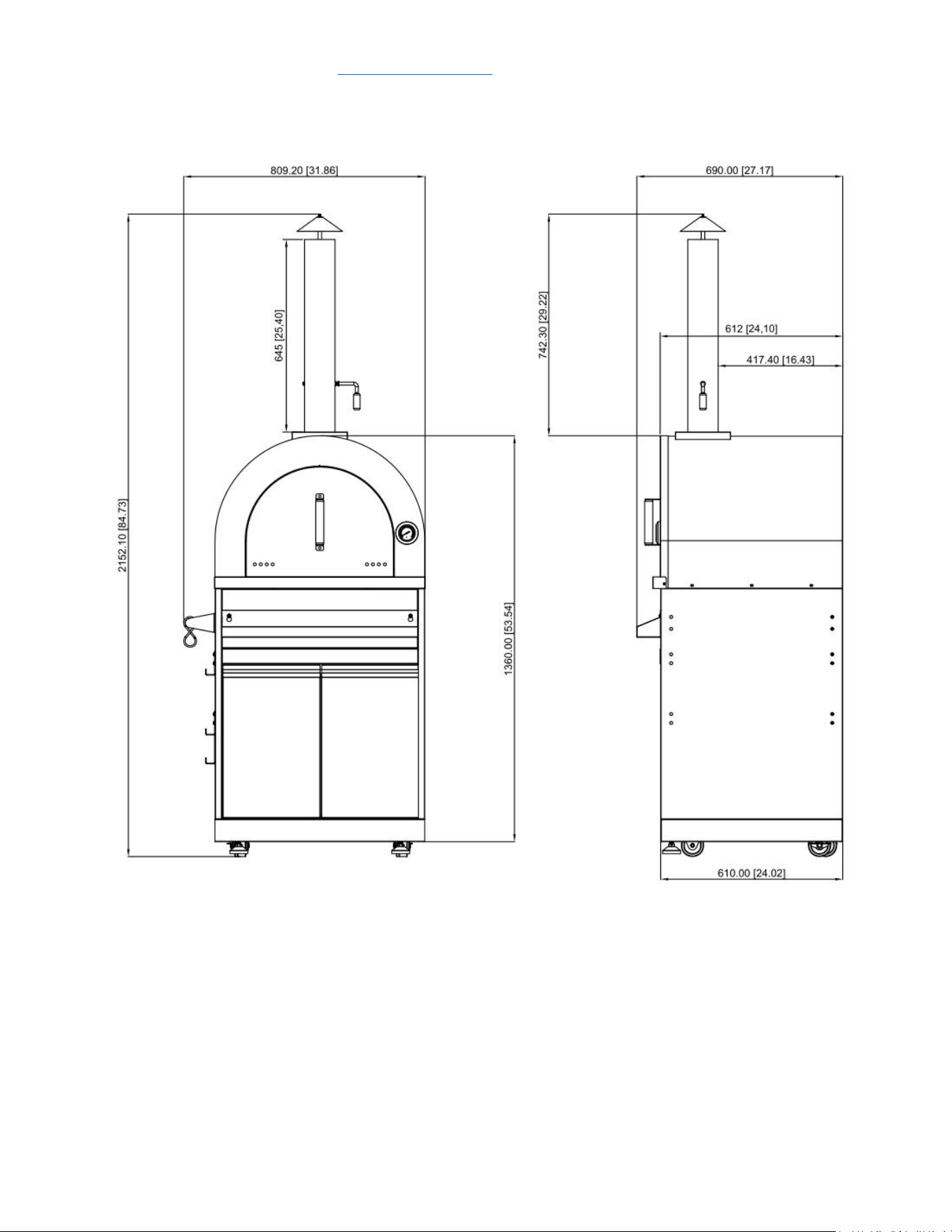
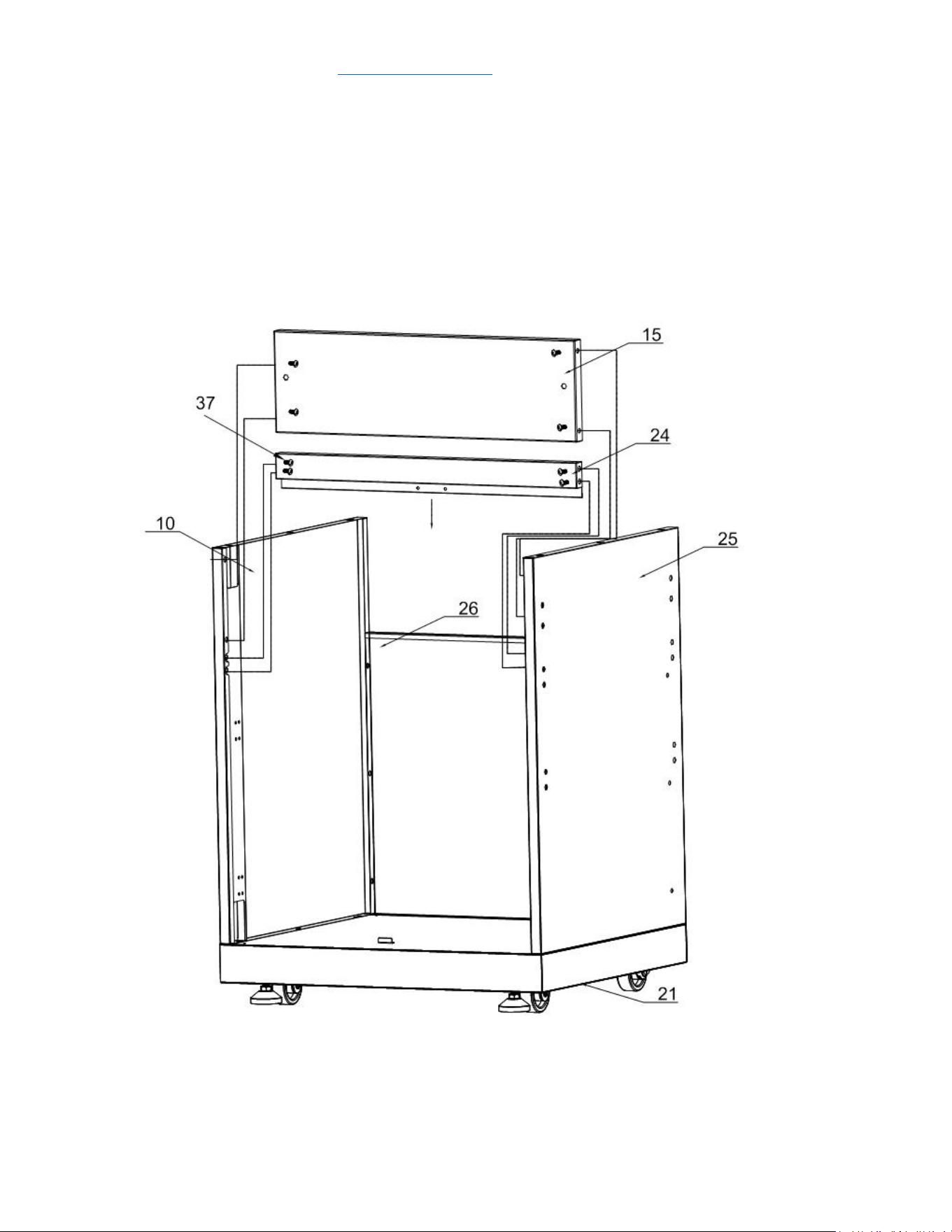
Model # MK07SS304 (Outdoor Pizza Oven Cabinet)

service@thorgroup.us +1 877-288-8099
Parts List
If you are missing any part, please contact Thor Kitchen Customer Service
Department at 877-288-8099 at business hours, or email service@thorgroup.us
for help.
Explosive #
Part #
Part Name
Quantity
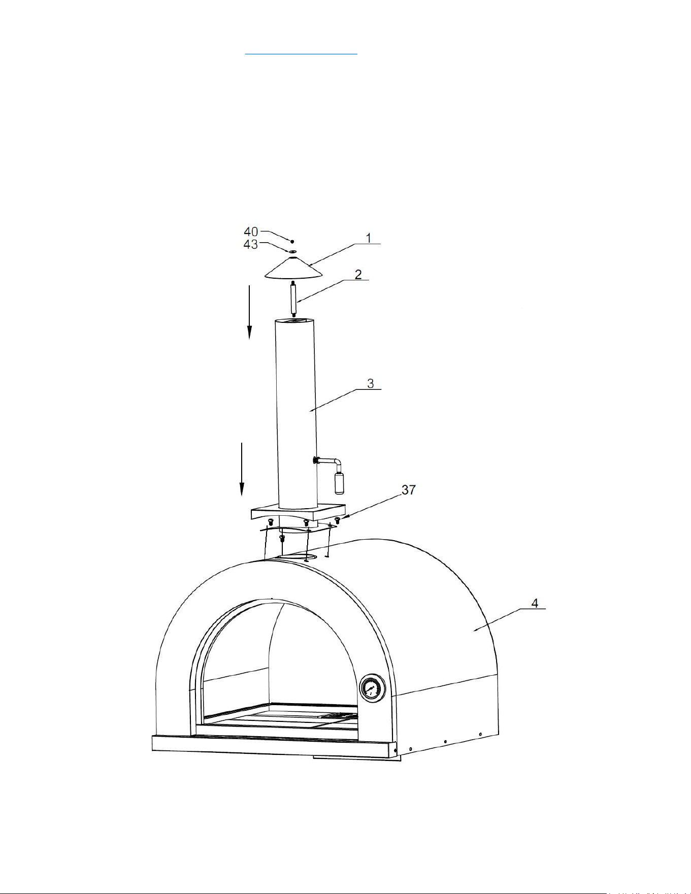
1
05.99.000119-000-A0
Chimney coping
1
2
05.19.008003-000-A0
Chimney supporting rod
1
3
22.99.009241-000-A0
Chimney pipe assembly
1
4
22.99.009239-000-A0
Pizza oven cavity
1
5
05.99.008024-000-A0
Thermometer
1
6
06.04.000377-000-A0
Mica plate 1
4
7
22.99.009243-000-A0
Pizza oven door handle assembly
1
8
20.01.008025-000-A1
Pizza oven door assembly
1
9
20.01.008022-000-A1
Beam welding assembly
1
10
20.01.008018-000-A0
Cabinet left side panel
1
11
20.99.000287-000-A0
Left/Right handle welding assembly
1
12
05.99.000202-000-A0
S-shape Pothook
1
13
04.02.002641-000-A0
Pothook 1
3
14
04.02.002642-000-A0
Pothook 2
1
15
20.01.008023-000-A0
Cabinet top panel welding assembly
1
16
20.01.008035-000-A0
Condiment storage welding assembly
1
17
04.01.002596-000-A1
Kick panel plate
1
18
05.01.008004-000-A0
Supporting leg
2
19
05.10.000122-000-A0
Fixed caster
2
20
05.10.000123-000-A0
Universal caster with brake
2
21
20.01.008076-000-A0
Cabinet bottom panel welding assembly
1
22
22.99.009235-000-A0
Left door assembly
1
23
22.99.009234-000-A0
Right door assembly
1
24
20.01.008022-000-A1
Beam welding assembly
1
25
20.01.008019-000-A0
Cabinet right side panel welding
assembly
1
26
20.01.008020-000-A0
back panel welding assembly
1
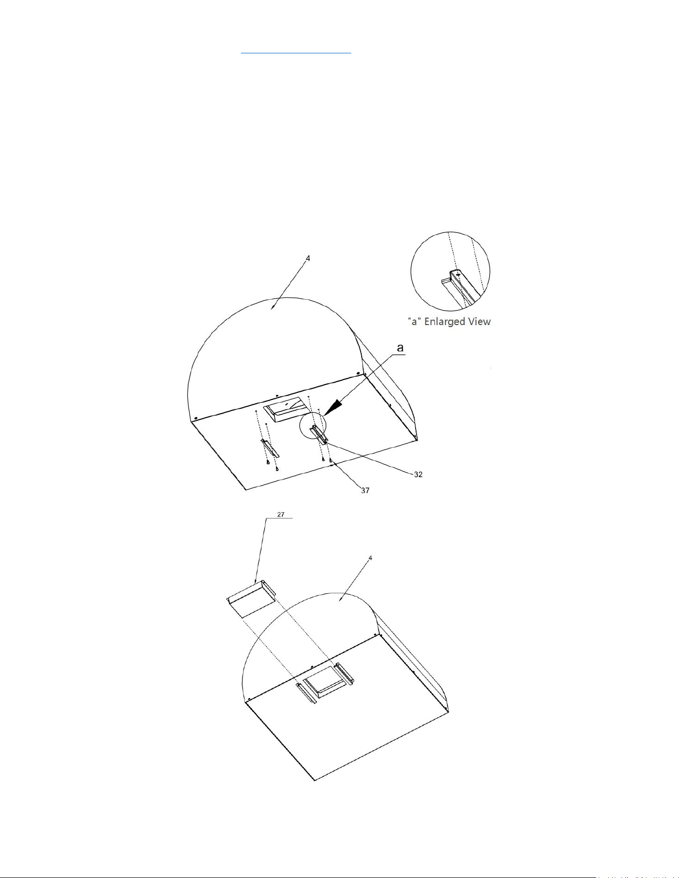
27
20.01.008006-000-A0
Ash pan welding assembly
1
28
15.99.000002-000-A0
Cordierite firebrick B
4
29
15.99.000001-000-A0
Cordierite firebrick A
2
30
04.01.008019-000-A1
Net Cover
1
31
05.03.008001-000-A0
Door hinge
4
32
04.01.008021-000-A0
Ash pan holder
2
33
05.99.000199-000-A0
Pizza wheel
1
34
05.99.000198-000-A0
Pizza cutter
1

service@thorgroup.us +1 877-288-8099
35
05.99.000200-000-A0
Pizza oven brush
1
36
05.99.000201-000-A0
Large pizza oven shovel
1
37
06.02.000093-000-A0
¼” Philips thumb head screw with anti-
slip design
65
38
06.10.000042-000-A0
Philips thumb head screw
2
39
06.11.008056-000-A0
flat head screw
24
40
06.09.000099-000-A0
1/4" nut
3
41
04.01.002580-000-A0
cabinet back connecting plate
2
42
04.01.002579-000-A0
cabinet front connecting plate
1
43
06.04.000030-000-A0
¼” flat gasket
3
44
06.09.000099-000-A0
¼” spring washer
2
service@thorgroup.us +1 877-288-8099
Cabinet Installation
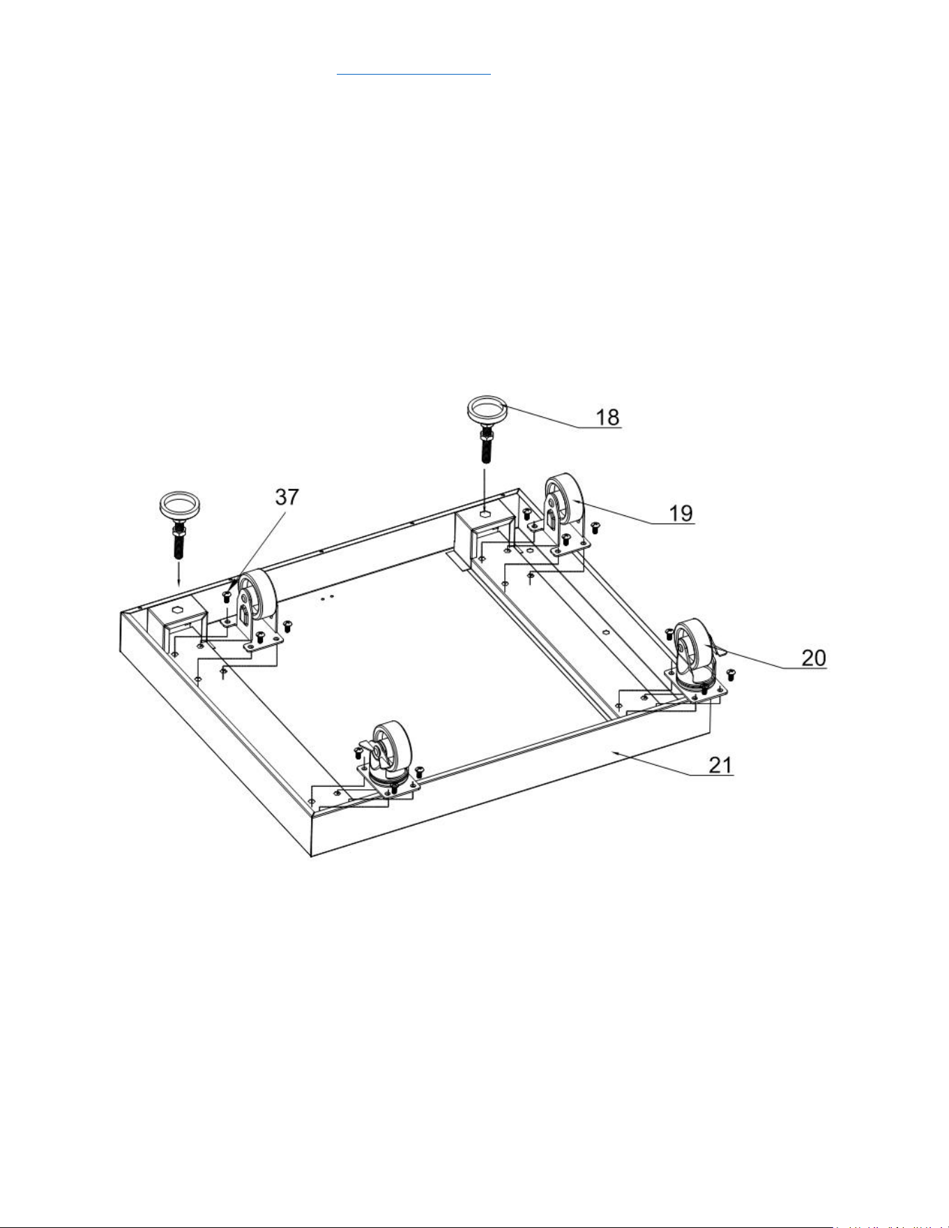
Step 1
1. Install 2 pcs supporting legs (Part # 18) to bottom welding part (Part # 21)
and adjust the supporting legs to suitable position;
2. Use 16 pcs ¼” flat Philip’s screw head (Part # 37) to connect 2 pcs fixed
casters (Part # 19) and 2 pcs universal casters with brake (Part # 20) to Part
#21;
service@thorgroup.us +1 877-288-8099
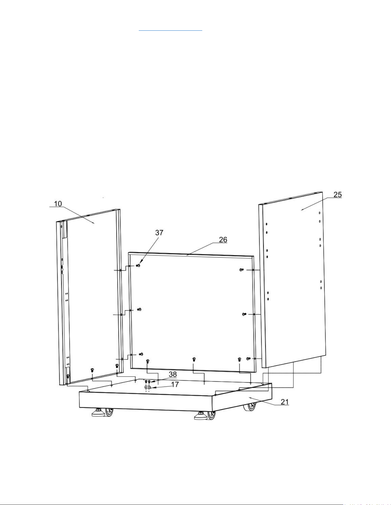
Step 2
1. Use 2 pcs Philips thumb head screw (Part # 38) to install Kick panel plate
(Part # 17) to Part # 21;
2. Use 3 pcs ¼” flat Philip’s screw head (Part # 37) to connect left side panel
(Part # 10) to Part # 21;
3. Use 3 pcs Part # 37 to connect right side panel (Part # 25) to Part # 21;
4. Use 8 pcs Part # 37 to connect back panel (Part # 26) to Part #21, # 10 and
#25;
5. Make sure all the connections are smooth, Do not over-tighten all the
screws until parts are lined up.

service@thorgroup.us +1 877-288-8099
Step 5
1. Use 2 pcs ¼” 14” screw (Part # 37) to go through the two holes on Pizza
oven door handle assembly (Part # 67), then go through 4 pcs mica plates
(Part # 6), 2 pcs ¼” flat gasket (Part # 43), 2 pcs ¼” spring gasket (Part # 44),
and 2 pcs ¼” hexagon nut (Part #40) to install Part # 7 to Pizza oven door
assembly (Part # 8).
service@thorgroup.us +1 877-288-8099
Step 7
1. Use 1 pc ¼” nut (Part # 40) and 1 pc ¼” flat gasket (Part # 43) to connect
chimney coping (Part # 1) to chimney supporting rod (Part # 2)
2. Install Part # 1 and # 2 to the top of Chimney Pipe Assembly (Part # 3);
3. Use 4 pcs ¼” flat Philip’s screw head (Part # 37) to connect Part # 3 to Pizza
Oven Cavity (Part # 4)
service@thorgroup.us +1 877-288-8099
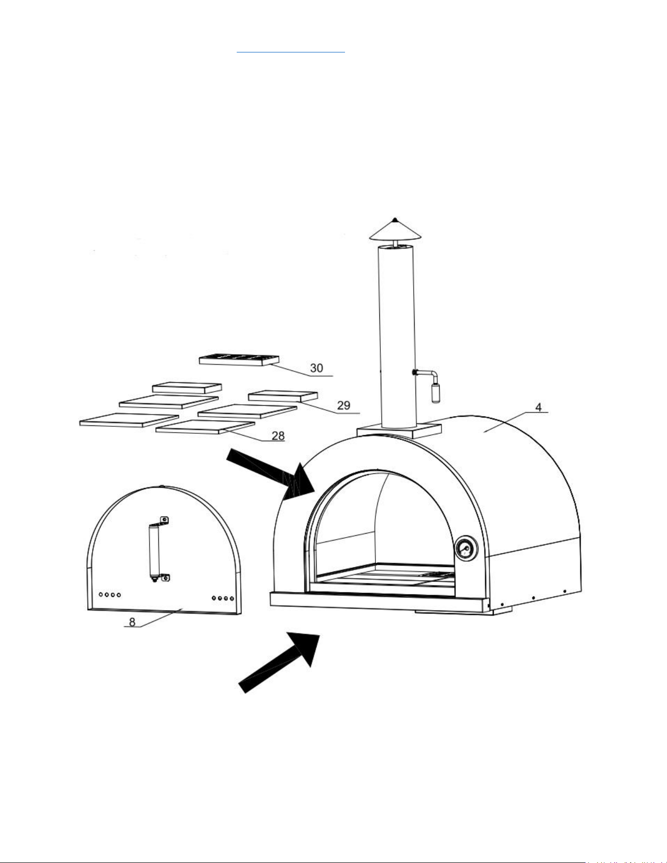
Step 8
1. Put 4 pcs Cordierite Brick B (Part # 28), 2 pcs Cordierite Brick A (Part # 29)
and 1 pc net cover (Part # 30) inside Pizza oven Cavity (Part # 4)
2. Insert Pizza oven door assembly (Part #8) into designated position on Part #
4.
3. Maximum Temperature inside the Pizza Oven Cavity is 800 F.
service@thorgroup.us +1 877-288-8099
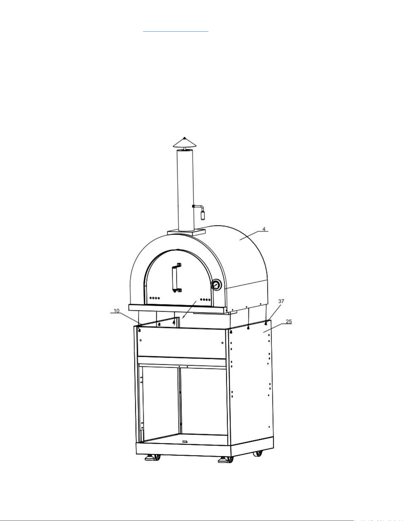
Step 9
1. Use 6 pcs ¼” Philips thumb head screw with anti-slip design (Part # 37) to
install Pizza oven cavity (Part # 4) to Cabinet left side panel (Part # 10) and
Cabinet right panel (Part # 25). Make sure the connection is smooth;
2. Do not over-tighten all the screws until parts are lined up.
service@thorgroup.us +1 877-288-8099
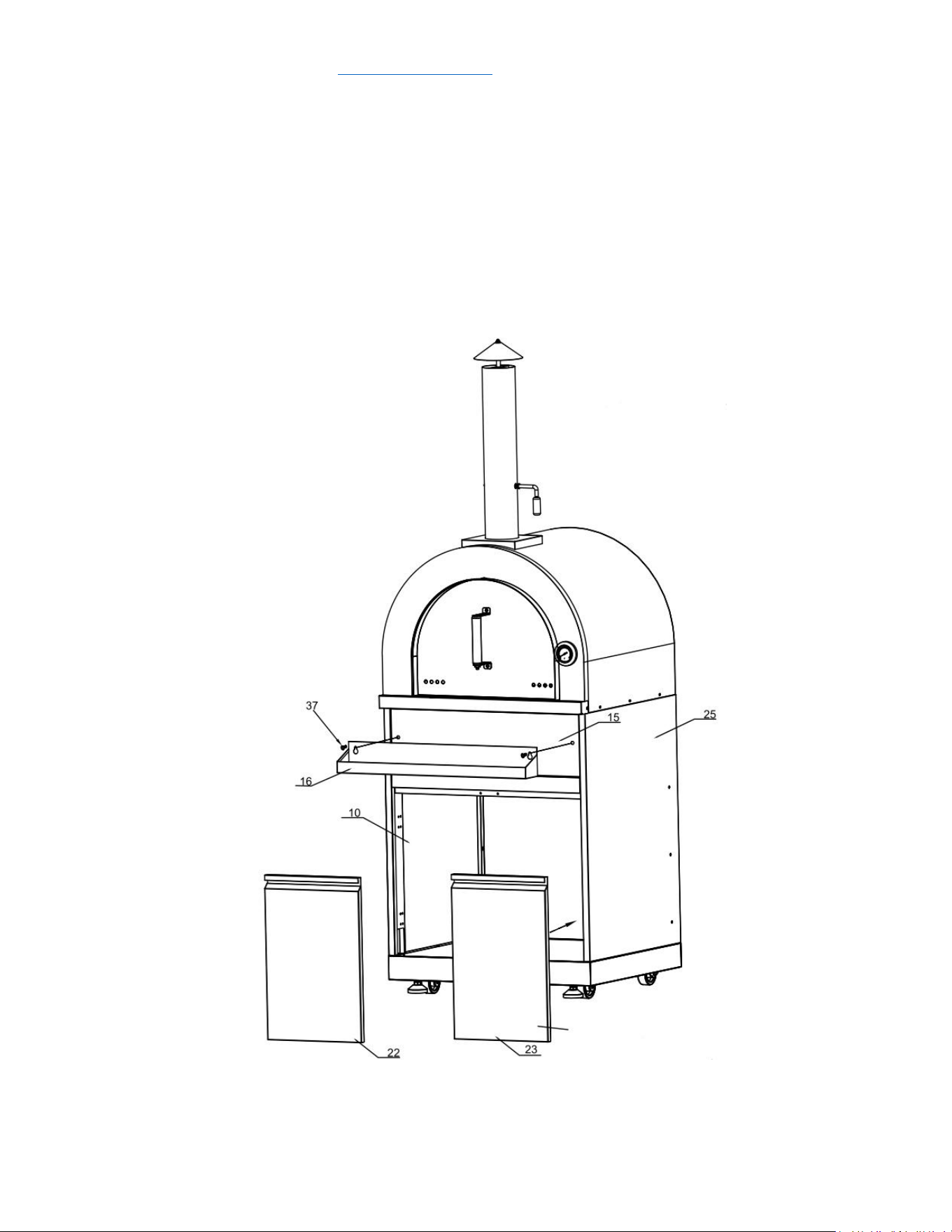
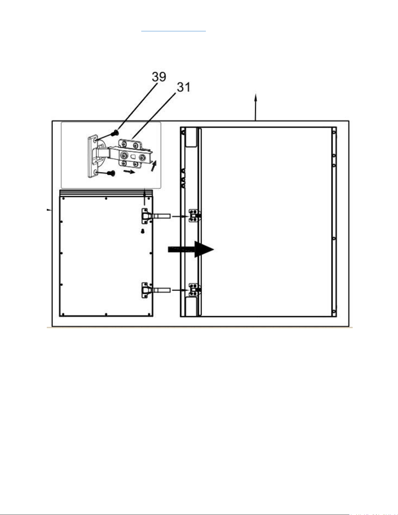
Step 10
1. Use 2 pcs Part # 37 to connect condiment storage welding assembly (Part #
16) to front panel assembly (Part # 15);
2. Use 24 pcs Parts # 39 to install door hinge (Part # 31) Part # 22 with Part #
10, and Part # 23 with Part # 25;
3. Connect Part # 22 with Part # 10 and connect Part # 23 with Part # 25;
4. Do not over-tighten all the screws until parts are lined up.
service@thorgroup.us +1 877-288-8099
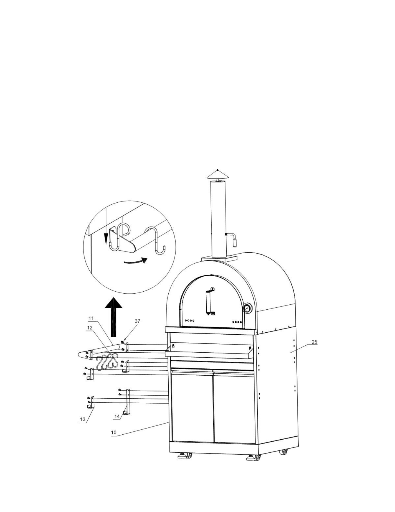
Step 11
1. Use 4 pcs Part # 37 to connect Left handle welding assembly (Part # 11) to
Left side panel (Part # 10), then put S-shape pothook (Part # 12) on Part #
11;
2. Use 8 pcs Part # 37 to connect side panel hook 1 (Part # 13) and side panel
hook 2 (Part # 14) to the left panel (Part # 10);
4. Part # 11, # 12, # 13 and # 14 could be installed on the right panel of pizza
oven cabinet (Part #2 5) if needed. Please make sure the connections are
smooth.

Warranty and Service
This product has been manufactured by Thor Group, 4651 E Airport Drive, California 91761
For Customer Service, please call (877) 288 - 8099
For the most up to date warranty and service policy, please refer to our website
WWW.THORKITCHEN.COM/WARRANTY-REGISTRATION
For in-warranty service requests, please visit our website at
WWW.THORKITCHEN.COM/SERVICE
Please Note: You must provide proof of purchase or installation date for any in-warranty service requests
WARRANTY REGISTRATION
Scan theQR code or visit
thorkitchen.com/warranty
Input your product info
and select register
You’re done.
Let’s get cookin’.
You chose THOR Kitchen to enhance your culinary journey and
we’re stoked to have you in the club. Think of it as a secret
society of really savvy people, such as yourself, choosing
professional power and performance at an affordable price.
Register your product by following the steps below.
WELCOME
TO THE CLUB
For additional information and product support, visit thorkitchen.com/service