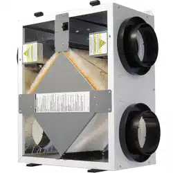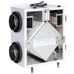
Model: TRe300 shown
TRe200 & TRe300 ERV
INSTALLATION, OPERATION & MAINTENANCE MANUAL
FOR SINGLE/MULTI-FAMILY
APPLICATIONS
WWW.SOLERPALAU-USA.COM
TRe-Series
ERV
WWW.SOLERPALAU-USA.COM INSTALLATION, OPERATION AND MAINTENANCE MANUAL 1.800.961.7370
2
RISK OF ELECTRIC SHOCK OR EQUIPMENT DAMAGE
Whenever electrical wiring is connected, disconnected or
changed, the power supply to the ERV and its controls must
be disconnected. Lock and tag the disconnect switch or
circuit breaker to prevent accidental reconnection of electric
power.
CAUTION
Only persons who have been properly trained and autho-
rized are to access the ERV electrical box and the controller.
Changes to the controller are to be made only by trained
and authorized personnel.
IMPORTANT
RISK OF INJURY FROM FALLING OBJECTS
Installation of this unit requires hoisting hardware overhead
and working directly beneath heavy objects during the
installation process. Observe all OSHA-approved work
practices. Always wear OSHA-approved Personal Protective
Equipment (PPE).
CAUTION
RISK OF CONTACT WITH HIGH SPEED MOVING PARTS
This appliance has two high speed fans that can cause
injury or be damaged if objects come into contact with the
impellers when they are spinning. The fans may be con-
trolled by external controlling devices and switch on at any
time. When working in the area of the fans, electric power
to the unit must be disconnected.
CAUTION
This equipment is to be installed by following industry best
practices and all applicable codes. Any damage to
components, assemblies, subassemblies or the cabinet
which is caused by improper installation practices will void
the warranty.
IMPORTANT
All ductwork is to be designed and installed in accordance
with SMACNA guidelines.
IMPORTANT
This ERV is intended for ducted ventilation only. Ducting at
least 40 inches [1 meter] in length must be installed on all
four airstreams.
IMPORTANT
TRe-Series ERV
3
1.800.961.7370 INSTALLATION, OPERATION AND MAINTENANCE MANUAL WWW.SOLERPALAU-USA.COM
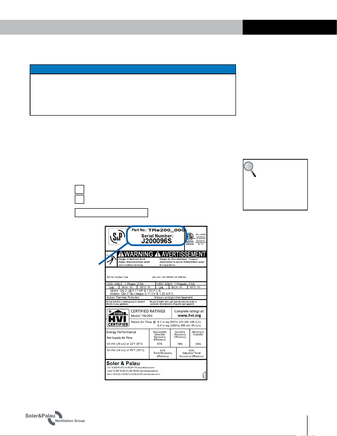
Record information as shown below. In the unlikely event that factory assistance is ever
required, this information will be needed.
ERV Model:
Locate the Soler & Palau unit label, to be found outside of the appliance. Record the model and
serial numbers below.
NOTE: This information is for purposes of identifying the specific air handling appliance. Unit-
specific option data can then be obtained, as needed, from the Model Number.
UNIT INFORMATION
TRe200
TRe300
NOTE: This page
is to be completed
by the installing
contractor. The completed
document is to be turned
over to the owner after
start-up.
UNIT INFORMATION
UNIT LABEL (TYPICAL)
OWNER INFORMATION
SAVE THIS MANUAL
This manual has space for recording operating settings at time of unit commissioning that
must be completed by the installer. See Sections 5.1 and 5.2 of this manual.
Information that is recorded is specific to just one ERV. If additional ERVs are being
documented, please make copies of these pages and identify each copy by its unit tag.
NOTICE
Serial Number:

TRe-Series
ERV
WWW.SOLERPALAU-USA.COM INSTALLATION, OPERATION AND MAINTENANCE MANUAL 1.800.961.7370
4
1.0 OVERVIEW 6
1.1 DESCRIPTION .........................................................6
1.2 OPERATING MODES ................................................6
1.3 UNIT WEIGHTS ........................................................7
2.0 COMPONENT DESCRIPTION 7
2.1 CABINET ................................................................7
2.1.1 Removable Door with Interlock Switch .................................7
2.2 FANS ...................................................................... 7
2.3 CONTROLLER .........................................................7
2.3.1 Controller Power Supply ...................................................... 7
2.4 DUCTS ...................................................................8
2.5 ENTHALPIC CORE ...................................................9
2.6 FILTERS ...............................................................10
2.7 CONTROLS TERMINAL STRIP ................................10
3.0 UNIT PLACEMENT 10
3.1 MOUNTING THE UNIT ............................................11
3.2 SERVICE CLEARANCES .........................................11
3.3 AC POWER SOURCE ..............................................11
3.4 LOAD BEARING CAPACITY OF SUPPORTS ..............11
4.0 INSTALLATION 12
4.1 USER-SUPPLIED INSTALLATION MATERIALS .......... 12
4.2 FACTORY-RECOMMENDED ELECTRIC
SERVICE ENTRY .........................................................12
4.3 FACTORY-RECOMMENDED LOW VOLTAGE
SERVICE ENTRY .........................................................12
4.4 ATTACHING DUCTS ...............................................12
4.5 SELECTING AIRFLOW SETTINGS ............................ 12
4.6 BALANCING AIRFLOWS .........................................12
4.7 WIRING SCHEMATICS............................................14
4.8 LOW VOLTAGE WIRING DIAGRAMS ......................... 15
4.8.1 Low Speed/High Speed Modes CONTINUOUS .................... 15
4.8.2 Low Speed CONTINUOUS/High Speed SWITCHED .......................... 15
5.0 OPERATION 15
5.1 MANOMETER READINGS AT COMMISSIONING .......15
5.2 AIRFLOW READINGS AT COMMISSIONING ..............16
5.2.1 Conversion of Pressure Drop to Airflow ............................. 16
5.2.2 Continuous Mode (low speed) ........................................... 16
5.2.3 Boost Mode (high speed) .................................................. 16
6.0 MAINTENANCE 16
6.1 MAINTENANCE AFTER 30 DAYS OPERATION ..........17
6.2 RECALIBRATION OF AIRFLOWS .............................17
6.3 DOOR REMOVAL ...................................................17
6.4 SERVICE PARTS .................................................... 17
7.0 TROUBLESHOOTING 18
7.1 INDICATION OF PROBLEM .....................................18
"
7.2 TRe HAS AIRFLOW BUT IS MAKING NOISE .............18"
7.3 NO APPARENT AIRFLOW FROM THE TRe ................18
7.4 INADEQUATE OR REDUCED AIRFLOW
F
ROM THE TRe...........................................................19
7.5 TRe FAILS TO RUN IN EITHER LOW SPEED
OR H
IGH SPEED..........................................................19
7.6 NO APPARENT REASON FOR LOW AIRFLOW ..........19
TABLE OF CONTENTS

TRe-Series ERV
5
1.800.961.7370 INSTALLATION, OPERATION AND MAINTENANCE MANUAL WWW.SOLERPALAU-USA.COM
Figure 1.2.0 TRe Cutaway View ....................................................6
Figure 2.1.0 Pressure Port Locations ............................................ 7
Figure 2.4.0 Airstream Illustration ................................................8
Figure 2.4.1 Separate Room Air Pick-up—Fresh Air to Furnace
Return Air Trunkline ..................................................................... 8
Figure 2.4.2 Separate Return Air and Fresh Air Supply .................9
Figure 2.4.3 Furnace Return Air back into Return Air ....................9
Figure 2.4.4 Furnace Return Air back into Supply Air ....................9
Figure 2.6.0 TRe Filter Locations ...............................................10
Figure 2.7.0 Controls Terminal Strip. .......................................... 10
Figure 3.1.0 Mounting the ERV to a Stud Wall ............................. 11
Figure 4.6.0 Pressure Port Locations ......................................... 13
Figure 4.6.1 Fan Speed Control Potentiometers .......................... 13
Figure 4.7.0 TRe Wiring Schematic ............................................. 14
Figure 4.8.0 Low Voltage Wiring Diagram 1 ................................ 15
Figure 4.8.1 Low Voltage Wiring Diagram 2 ................................ 15
Figure 5.2.0 Pressure Drop to Airflow Conversions ..................... 16
Figure 6.4.0 TRe Service Parts .................................................. 17
TABLE OF CONTENTS
TABLE OF ILLUSTRATIONS
TRe-Series
ERV
WWW.SOLERPALAU-USA.COM INSTALLATION, OPERATION AND MAINTENANCE MANUAL 1.800.961.7370
6
1.0 OVERVIEW
1.1 DESCRIPTION
1.2 OPERATING MODES
The TRe ERVs are multi-speed air-to-air energy recovery ventilators that are designed for
residential application and have multiple installation options. They can be suspended from
floor joists, or they can be mounted on a wall or other object. Each type of installation can be
accomplished by a single person. The TRe has an integral line cord, ready to be plugged into a
standard 120 VAC receptacle.
The ERV exhausts stale room air (RA) while transferring both latent and sensible energy
between an incoming fresh outdoor airstream (FA). Energy recovery is accomplished by a static
plate heat exchanger core. Each airstream has a 120 V EC fan, which provides airflow from 30
to 225 CFM for the TRe200 and from 30 to 280 CFM for the TRe300.
The airflow rate can be changed from Continuous to Boost at any time, using many different
optional sensors or control devices.
The unit may operate with balanced or unbalanced airflow. However, balanced airflow provides
the best energy recovery. Airflow can be adjusted using the motor potentiometers and the
values read via the door pressure taps.
The hinged door has an opening for viewing and access to the potentiometers. The entire
cabinet is lined with foil-backed 1" thick foam insulation.
OVERVIEW
NOTE: This unit is
an Energy Recovery
Ventilator, or ERV.
It is commonly referred to
throughout this manual as
an ERV.
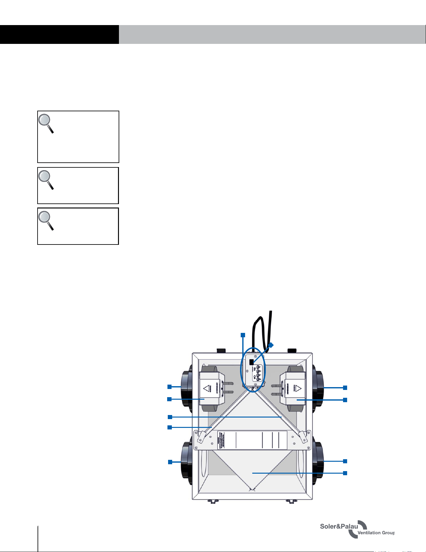
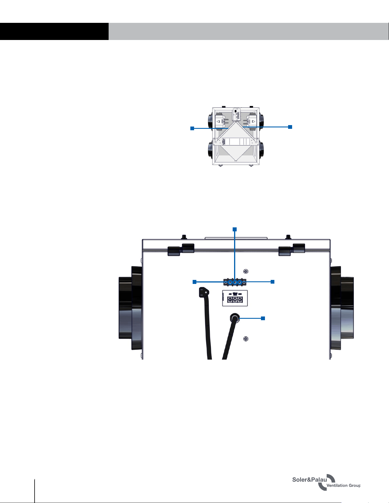
FIGURE 1.2.0 TRe CUTAWAY VIEW
RETURN AIR
DUCT
SUPPLY AIR
DUCT
ENTHALPIC
CORE
EXHAUST AIR
DUCT
OUTSIDE AIR
DUCT
ELECTRICAL BOX
AIR FILTERS
INTERLOCK
SWITCH
SUPPLY AIR
FAN
EXHAUST AIR
FAN
NOTE: Sensible
energy is often
referred to as
“heat energy.”
NOTE: Latent
energy is often
referred to as
“moisture energy.”
The TRe has two different operating modes: Continuous and Boost. Continuous mode should
be set to provide the minimum ventilation requirement. Boost mode can be used to supply and
exhaust a greater volume of air, up to 225 CFM for the TRe200 or 280 CFM for the TRe300.
The two operating modes are selectable and controlled independently so that different
controlling methods can be used to switch back and forth. Example: an IAQ sensor could be
used to switch the unit to Boost mode.
TRe-Series ERV
7
1.800.961.7370 INSTALLATION, OPERATION AND MAINTENANCE MANUAL WWW.SOLERPALAU-USA.COM
2.0 COMPONENT DESCRIPTION
2.1 CABINET
2.2 FANS
2.3 CONTROLLER
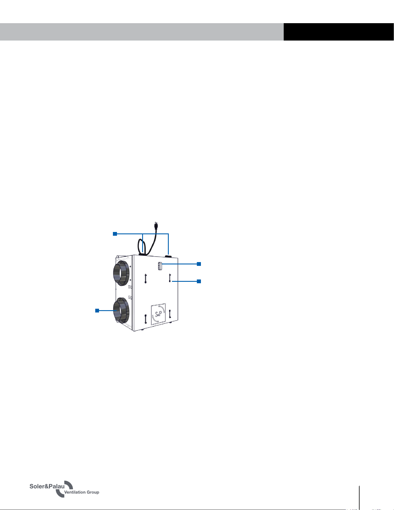
The cabinet is built of 22 gauge (0.64 mm) galvanized steel and is painted white. It has a
hinged, removable door. The exterior of the unit boasts four air pressure test ports, one low-
voltage terminal strip, an access/viewing port, and locations for four duct connectors, (6" or 8",
shipped loose).
2.1.1 Removable Door with Interlock Switch
The insulated access door is hinged on one side and has two securing latches on the other side.
The hinges are separable to allow for removal of the access door for servicing. The door has an
access/viewing port built in to permit adjustment of the fan potentiometers. Directly behind the
access door is a pressure-sensitive interlock switch that will shut off power to the unit if the
door is opened during operation. Also installed on the door are four air pressure test ports, used
for connecting a manometer and taking air pressure measurements.
The TRe has two advanced, high efficiency electronically commutated (EC) 120 VDC variable
speed fans. One fan is used for intake air (Outdoor Air/Supply Air) and the other fan is for the
exhaust airstream (Return Air/Exhaust Air). The speed of each fan is controlled independently
by a 0–10 VDC signal from the controller.
The controller provides the signal to the EC motors using integral potentiometers. Incoming line
voltage powers both fans and also a step-down Class II transformer which provides 24 VAC to
the externally-mounted low-voltage terminal strips. The controller has four potentiometers that
are adjusted by the user to establish fan speeds for each operation mode.
1.3 UNIT WEIGHTS
The hanging weight of each TRe200 is approximately 36 pounds.
The hanging weight of each TRe300 is approximately 52 pounds.
COMPONENT DESCRIPTION
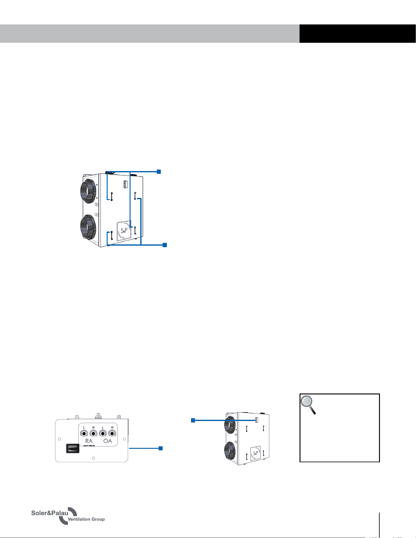
FIGURE 2.1.0 PRESSURE PORT LOCATIONS
The shipping weight of each TRe200 is approximately 48 pounds.
The shipping weight of each TRe300 is approximately 66 pounds.
2.3.1 Controller Power Supply
Each TRe has one terminal strip mounted on the end of the unit. The terminal strip is a 24 VAC
power supply terminal. The unit control board provides up to 6 VA (approximately 0.25 A) which
can be used to power the various optional control accessories.
AIR PRESSURE
TEST PORTS (4)
DUCT CONNECTORS (4)
SEPARABLE HINGES (2)
ACCESS/VIEWING PORT
TRe-Series
ERV
WWW.SOLERPALAU-USA.COM INSTALLATION, OPERATION AND MAINTENANCE MANUAL 1.800.961.7370
8
2.4 DUCTS
TRe units are supplied with a set of 4 duct connectors that must be field-installed. The
connectors can be used for either 6" round or 8" round ducts. It is preferable to keep duct runs
short and straight to maximize performance.
For all installations, SMACNA guidelines for duct installation should be followed. The most
commonly-used ducting is 6" diameter flexible due to ease of installation, sound attenuation,
and cost, however, rigid ducting is preferred because there is less resistance to airflow,
resulting in less power consumption to deliver the same amount of air.
A total of four duct runs will generally be used:
u
One duct will provide clean outdoor air (Outside Air) to the TRe. This duct will normally be
capped by an air inlet cap mounted on the exterior side wall of a residence and equipped with
a bird screen.
Wall intakes must be located at least 10' from any appliance vent or any vent opening from
a plumbing drainage system. Wall intakes must also be 10' from any exhaust fan discharge
outlet unless that outlet is 3' or more above the intake location. (IRC 2006, Section M1602.2)
u
One duct will be needed to exhaust stale air (Exhaust Air) to the outdoors. This duct will
normally end at an exhaust cap located on an exterior wall of a residence.
u
One duct will be needed to deliver fresh, conditioned air (Supply Air) from the TRe to a
desired location in the residence. The Supply Air duct may end in a floor or wall grate with
an area of at least 28 square inches. Alternatively, the Supply Air duct may be connected
directly into the return air duct or the supply air duct for the main heating and cooling system.
When connecting to the main return air duct, it must be at least 3' from the return plenum to
minimize suction from the furnace blower.
u
One duct is used to collect indoor air (Return Air), running from return grilles through the
energy exchange core in the TRe before being exhausted to the outdoors.
If the TRe is located in a conditioned space, only the OA and EA ducts need to be insulated.
If it is installed in an unconditioned space such as an attic or crawl space, the SA, OA, RA, and
EA ducts must be insulated.
COMPONENT DESCRIPTION
NOTE: For all units:
RA = Room Air into
unit
OA = Outside Air into unit
SA = Supply Air to inside
EA = Exhaust Air to outside
NOTE: Ducts inside
a building that are
connected to the
outside must be
insulated with a sealed
vapor barrier on both the
inside and the outside of the
insulation.
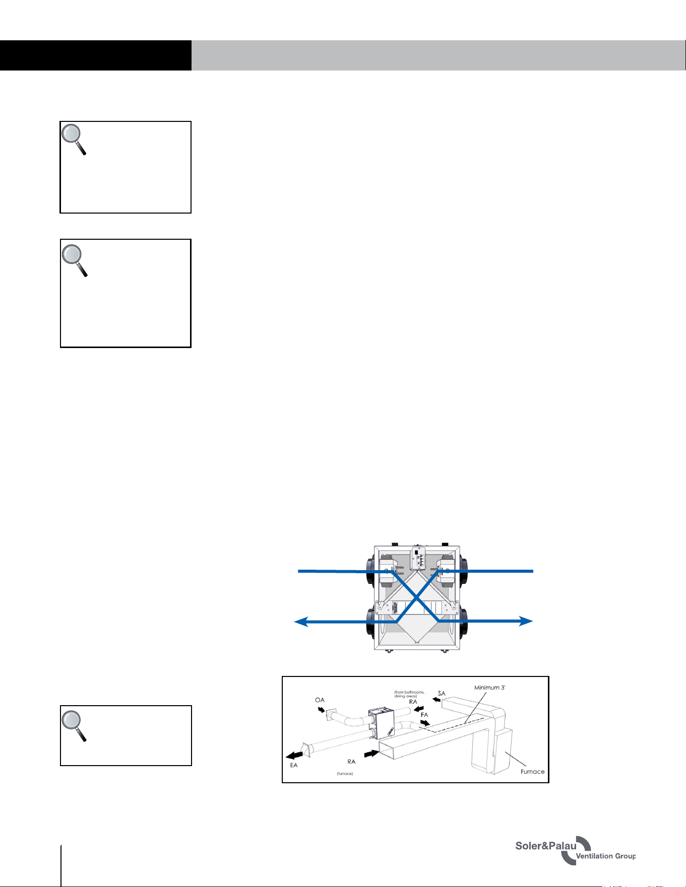
FIGURE 2.4.0 AIRSTREAM ILLUSTRATION
EXHAUST AIR
(TO OUTDOORS)
SUPPLY AIR
(TO OCCUPIED SPACE)
RETURN AIR
(FROM OCCUPIED SPACE)
OUTSIDE AIR
(INTO UNIT)
NOTE: ERV blower
may be operated
separate from
furnace blower.
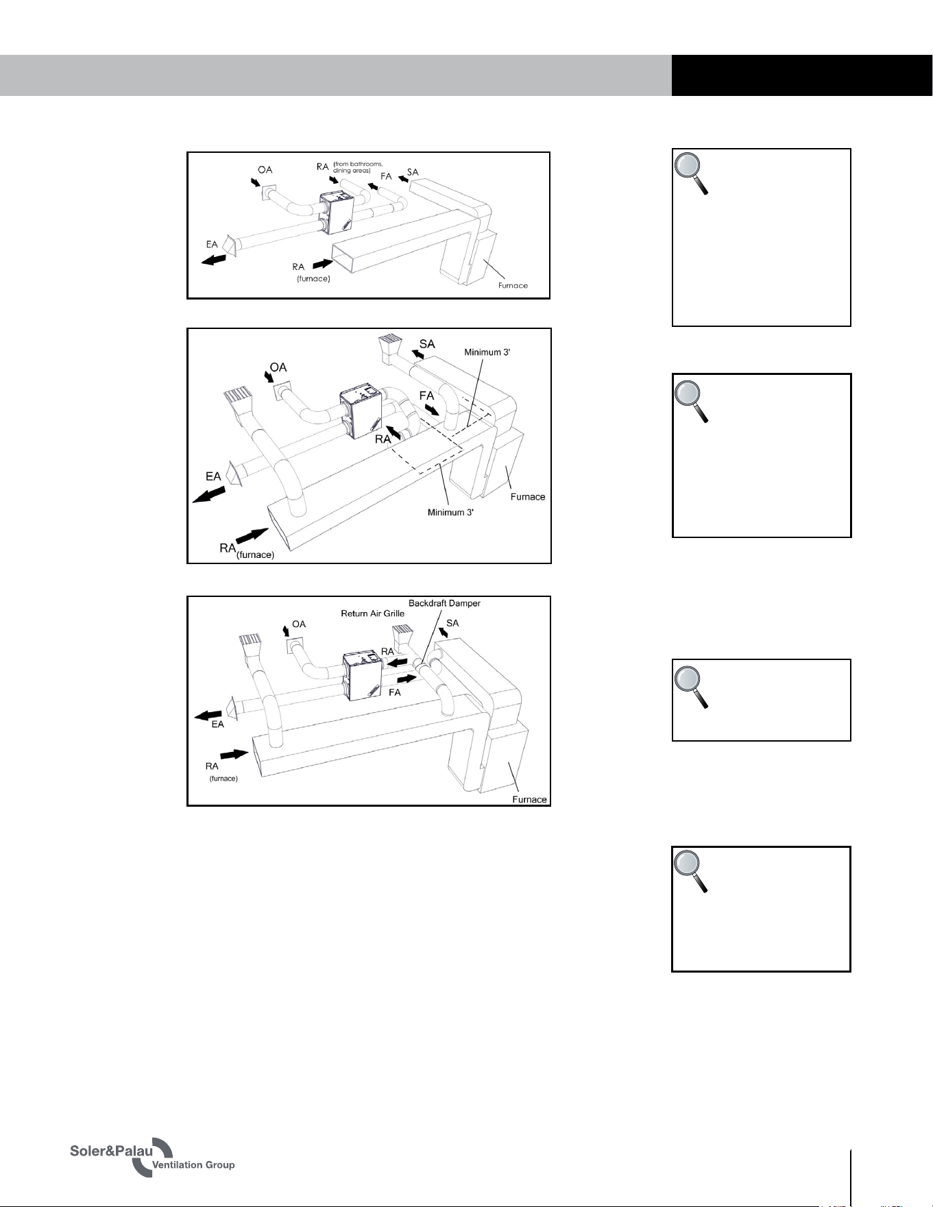
FIGURE 2.4.1 SEPARATE ROOM AIR PICK-UP—FRESH AIR TO FURNACE RETURN AIR TRUNKLINE
TRe-Series ERV
9
1.800.961.7370 INSTALLATION, OPERATION AND MAINTENANCE MANUAL WWW.SOLERPALAU-USA.COM
NOTE: For the
setup in Figure
2.4.3, the furnace
blower must be op-
e
rated any time the ERV is
operated. Use furnace fan
“on” continuous low speed
or optional SFM control to
cycle furnace fan on ERV.
FIGURE 2.4.3 FURNACE RETURN AIR BACK INTO RETURN AIR
FIGURE 2.4.2 SEPARATE RETURN AIR AND FRESH AIR SUPPLY
NOTE: ERV blower
may be operated
independently from
furnace blower.
Use caution to introduce FA
at low velocity and where
good mixing will occur to
minimize discomfort from
drafts
NOTE: ERV blower
may be operated
separate from
furnace blower.
FIGURE 2.4.4 FURNACE RETURN AIR BACK INTO SUPPLY AIR
COMPONENT DESCRIPTION
2.5 ENTHALPIC CORE
Each TRe has a static-plate, cross-flow core separates the outgoing, polluted indoor airstream
from the incoming fresh airstream—while simultaneously transferring total energy (heat and
water vapor) between the two. Airstreams do not mix, and pollutants are not transferred across
partition plates.
NOTE: The cores
used in all ERVs
are static plate
enthalpic cores. They are
commonly referred to in
this manual as “cores.”
TRe-Series
ERV
WWW.SOLERPALAU-USA.COM INSTALLATION, OPERATION AND MAINTENANCE MANUAL 1.800.961.7370
10
UNIT PLACEMENT
2.7 CONTROLS TERMINAL STRIP
A single terminal strip is located at the end of each TRe, providing a 24 VAC connection to Boost
mode or to control accessories. For detailed information, see the Low Voltage Wiring Diagrams
in Section 4.8 of this manual.
FIGURE 2.7.0 CONTROLS TERMINAL STRIP
3.0 UNIT PLACEMENT
Soler & Palau recommends installation of the TRe by a professional HVAC installer with
knowledge of local building codes who is able to properly balance the air streams prior to use.
The TRe can be installed by one person.
24 VAC
COMMON
HIGH SPEED
(BOOST) MODE
120 VAC LINE
CORD
2.6 FILTERS
Each TRe is equipped at the factory with mesh-type anti-microbial MERV 8 filters on both
the OA and RA sides of the core. If desired, the mesh-type OA filter can be replaced with an
optional MERV 13 pleated paper filter accessory, which will ship loose.
FIGU
RE 2.6.0 TRe FILTER LOCATIONS
OA FILTER (FILTERS THE INCOMING
OUTDOOR AIR FOR USE IN THE OCCUPIED
SPACE AND ALSO PROTECTS THE CORE).
THIS FILTER CAN BE REPLACED WITH A
PLEATED PAPER MERV 13 FILTER.
RA FILTER (PROTECTS THE
CORE FROM DUST AND DIRT
BEING CARRIED BY THE RETURN
AIRSTREAM)
UNIT PLACEMENT
TRe-Series ERV
11
1.800.961.7370 INSTALLATION, OPERATION AND MAINTENANCE MANUAL WWW.SOLERPALAU-USA.COM
UNIT PLACEMENT
3.2 SERVICE CLEARANCES
Primary consideration is sufficient space to open door latches and for the door to be able to
swing open at least 90°. See the dimensioned drawing in the front of this manual for required
clearances.
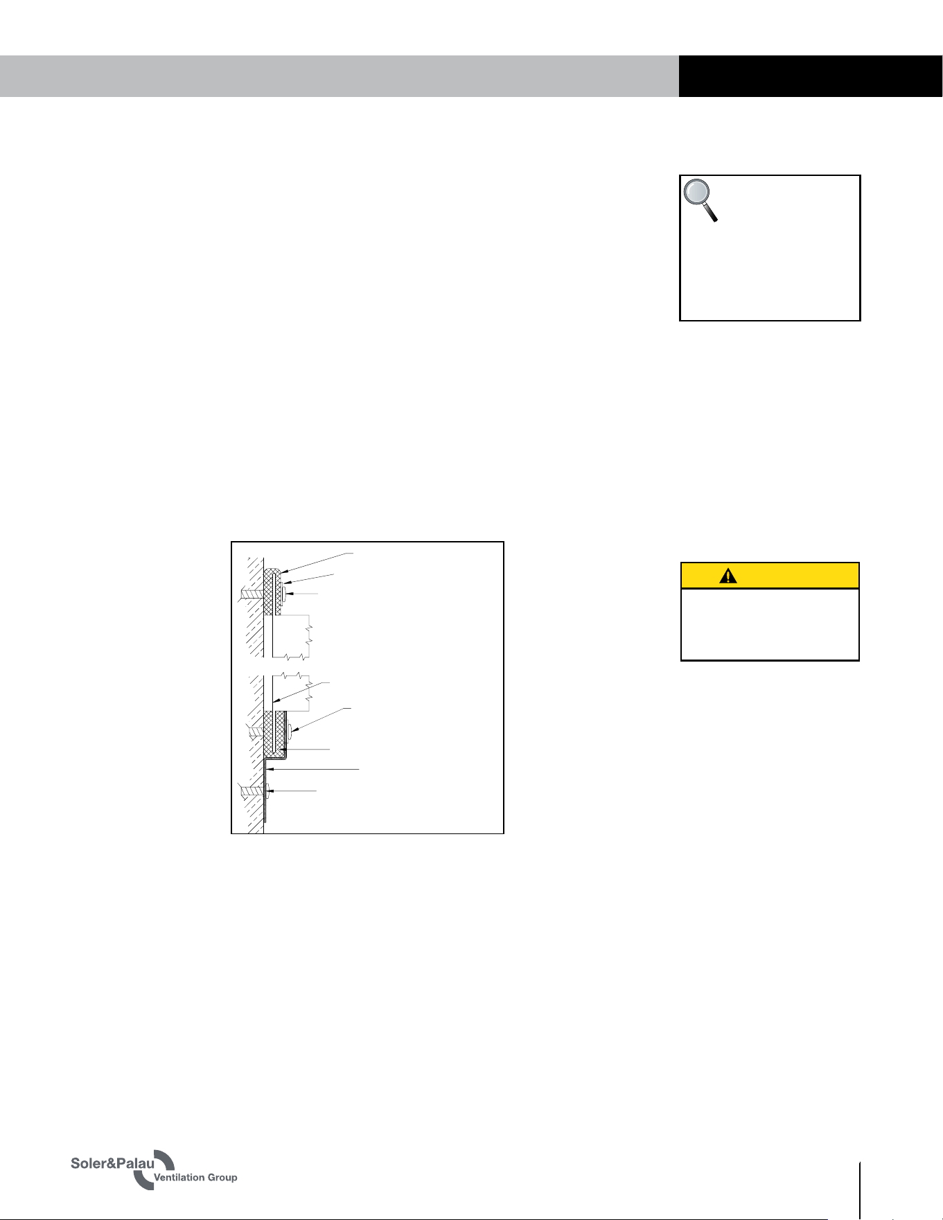
Foam Tape
Foam Tape
Metal Washer
Lag Screw or Concrete Anchor
(provided by others)
Lag Screw or Concrete Anchor
(provided by others)
Unit Flange
Optional Washer and Screw
(provided by others)
Hanging Bracket
FIGURE 3.1.0 MOUNTING THE ERV TO A STUD WALL
Risk of injury when lifting
unit and installing it
overhead.
CAUTION
3.3 AC POWER SOURCE
Power requirements: 120 VAC, 3.0 amps
The TRe has an integral 34 inch long power supply cord. The installer must provide a standard,
grounded 120 VAC outlet in the proximity of the ERV. Check all local codes.
3.4 LOAD BEARING CAPACITY OF SUPPORTS
The TRe ERV is to be installed by attachment to building structural members such as joists, bar
joists, beams, wall studs and columns. It is not be supported by attachment to fixtures such as
ductwork or air handlers unless the fixtures are permanently installed and capable of providing
adequate support. Whenever an ERV is installed on or supported by a fixture, the installation
must be approved by a design engineer.
3.1 MOUNTING THE UNIT
u
UNIT MAY BE INSTALLED IN ANY ORIENTATION
Orient the unit for the simplest duct layout and connections.
May be installed in any position providing sufficient clearance as shown in the front of this
manual. Preferred position is horizontal so that the hinged access door can swing down to
allow for easiest filter changes and cleaning of the enthalpic core.
u
MOUNTING THE TRe ON A CONCRETE FOUNDATION WALL OR STUD WALL
Mount hanging bracket to the wall with appropriate concrete anchors. Use pre-cut foam tape
from small parts bag. Remove backing and apply two pieces of foam tape equally spaced
along the unit’s mounting flange to be held by the hanging bracket. Apply the other two
pieces of foam over two holes that will be used for fastening, on the other flange. The tape
should be applied in a “U” shape to cushion both the front and back of the integral flanges.
Lift unit and slide unit flange into the hanging bracket. Using metal flat washers, fasten
flange opposite hanging bracket to structure. Safety screws should similarly be installed
passing through the hanging bracket and flange. Make sure the screws, which you must
supply, are properly selected for the loads and substrate involved, 2" x #10 pan head screws
are recommended.
u SUSPENDING THE TRe FROM FLOOR JOISTS OR TRUSSES
The unit may be screwed directly to joists or trusses using the hanging bracket and integral
flange. Mount as described for mounting to concrete foundation wall.
NOTE: The door
is equipped with
slide-off hinges.
For the homeowner’s
convenience,it is helpful
to orient the unit so that
the door is easily removed
when unlatched.
TRe-Series
ERV
WWW.SOLERPALAU-USA.COM INSTALLATION, OPERATION AND MAINTENANCE MANUAL 1.800.961.7370
12
INSTALLATION
4.6 BALANCING AIRFLOWS
TRe ERVs provide the ability to deliver and exhaust completely balanced airflows, or to modify
them as desired. While balanced airflow is preferred, many owners will prefer to have a slight
imbalance, providing a slight excess of Outdoor Air to reduce air infiltration into a home. Some
homes may require an imbalance because a furnace or water heater is not direct-vented.
Again, an HVAC professional will be able to advise balance settings that will best address the
circumstances in each home.
Balancing an airflow is done by setting the Outdoor Air fan speed and then adjusting the Return
Air fan speed to eject the same or somewhat less air to the outdoors.
4.0 INSTALLATION
4.1 USER-SUPPLIED INSTALLATION MATERIALS
Soler & Palau suggests the use of a duct hoist for hoisting the TRe into position.
For all installations:
u
Medium-strength thread-lock,
u
UL-181—rated mastic for duct connections,
u
Common hand tools such as pliers, drill, screwdriver bits, stud finder, etc.
RISK OF INJURY FROM FALLING OBJECTS
Installation of this unit requires hoisting hardware overhead and working directly beneath
heavy objects during the installation process. Observe all OSHA-approved work practices.
Always wear OSHA-approved Personal Protective Equipment (PPE).
CAUTION
NOTE: Wall
brackets must be
supported by two
wall studs. If the desired
location of the TRe does
not permit support by two
wall studs, the TRe must
be mounted on a user-sup-
plied 3/4" thick plywood
panel that is anchored on
two wall studs.
4.3 FACTORY-RECOMMENDED LOW VOLTAGE SERVICE ENTRY
4.4 ATTACHING DUCTS
Ducts are to be fabricated and installed per SMACNA guidelines. Use a combination of zip ties,
UL-181—rated duct mastic and then secure the duct from slipping off by means of a screw,
positioned behind one or more ribs in the duct. Observe Industry Best Practices when installing
and supporting the ducts.
All low voltage connections are made on the exterior of the unit on the low voltage terminal
strip. Field-installed low voltage wiring does not enter the unit.
4.2 FACTORY-RECOMMENDED ELECTRIC SERVICE ENTRY
Model TRe has a factory-installed 34" line cord that will need to be plugged into a 120 V
receptacle for operation.
4.5 SELECTING AIRFLOW SETTINGS
The need for boost mode varies by situation. For example, boost mode could be tied to
bathroom and shower usage. Alternatively, boost mode might be set for specific times of the
day when more people will be in the space being ventilated. In all cases, an HVAC professional
should be consulted to determine how to best set the airflow volumes to provide maximum
benefit to the inhabitants.
Airflow volumes are set by taking pressure readings at the pressure ports in the unit door and
then adjusting the potentiometers, first the two low speed ones, then the two high speed ones.
Normally, the low-speed OA and RA potentiometers are set and then the readings are compared
to the chart in Section 5.2.1 of this manual. Measuring the pressure drop across the core for
each airstream is used to determine the airflow volume.
NOTE: Airflow
volumes can be
changed at any
time by the user as expe-
rience dictates. Whenever
changing airflow volumes
for either Continuous (low
speed) or Boost (high
speed) modes, the fans
should again be balanced.
TRe-Series ERV
13
1.800.961.7370 INSTALLATION, OPERATION AND MAINTENANCE MANUAL WWW.SOLERPALAU-USA.COM
INSTALLATION
u
Verify the unit has clean filters in place.
u
Open the pressure port caps for the OA airstream and then insert the tubing into the openings
about 1".
u
Take a differential pressure reading for the OA airstream and compare the pressure drop to
the chart in Section 5.2.1 to obtain the CFM. Adjust the fan speed potentiometer (see Figure
4.6.1) to obtain the desired CFM. Enter the CFM information in the box in Section 5.2.2.
u
Take a differential pressure reading on the RA airstream and compare the pressure drop
to the table in Section 5.2.1 to find the CFM of the RA airstream. Adjust the RA fan speed
potentiometer to obtain the desired balance. Enter the CFM information into the box in
Section 5.2.2.
u
Install a jumper on the low voltage terminal to force the unit into Boost (high speed) mode.
See the wiring diagram in Section 4.7.
u
Repeat the process for both airstreams to set both the CFM and balance. Enter the
information in the boxes in Section 5.1.
u
After adjusting the potentiometers, take additional readings as needed to verify that fan
speed settings are correct. See Figure 4.6.1.
FIGURE 4.6.0 PRESSURE PORT LOCATIONS
FIGURE 4.6.1 FAN SPEED CONTROL POTENTIOMETERS
POTENTIOMETERS ARE VISIBLE
AND ACCESSIBLE THROUGH THE
OPENING IN THE UNIT DOOR
NOTE: Adjust low
speed fan set-
tings by using the
potentiometers marked
“L.” Adjust high speed
fan settings by using the
potentiometers marked
with “H.”
USE THESE TWO PRESSURE PORTS TO
CHECK PRESSURE DROP FOR THE RA
AIRSTREAM
USE THESE TWO PRESSURE PORTS TO
CHECK PRESSURE DROP FOR THE OA
AIRSTREAM
Equipment required for testing airflows:
u
A magnehelic gauge (or manometer) or other device capable of measuring 0–1.0 inches water
gauge of differential pressure.
u
2 pieces of natural rubber latex tubing, 1/8" I.D., 1/16" wall thickness works best.
Manometers are relatively inexpensive devices that are readily available from online retailers;
accuracy within the range of 0–1.0 in. w.g. is the critical measure. Water manometers generally
have graduations of 0.1" that are difficult to accurately determine. For all manometers, there
are two plastic tubes that connect at the manometer and then the other ends go to pressure
ports on the TRe.
Individual differential static pressures (DP) are measured ACROSS the core, using the installed
pressure ports located on the removable door.
TRe-Series
ERV
WWW.SOLERPALAU-USA.COM INSTALLATION, OPERATION AND MAINTENANCE MANUAL 1.800.961.7370
14
INSTALLATION
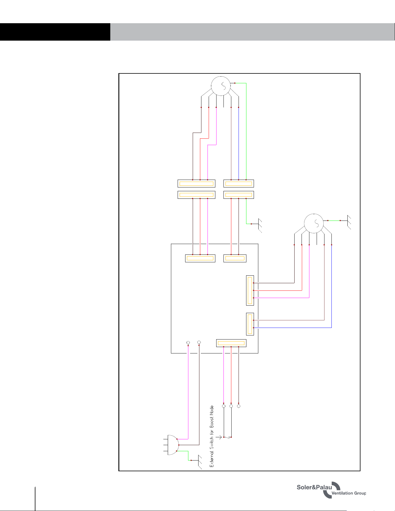
4.7 WIRING SCHEMATICS
CHANGESNAMEREV. DATE
SCHEME
Standard
RenewAire
1
A B C D E
New0
1
Tandem_Field
2
3
4
5
6
7
8
9
10
11
12
13
Input Power
115 VAC, 1 Phase
M
SF Motor
M
EF Motor
SF_ECM_LOW
SF_ECM_HIGH
Line Cord
120VAC
120COM
24VAC
HIGH
COM
EF_ECM_HIGH
EF_ECM_LOW
Control Board
BK
RD
YL
BR
BU
GN/YL
BK
RD
YL
BR
BU
GN/YL
WHT
RD
BK
RD
BK
GN/YL
BK
RD
WHT
WHT
BK
GN/YL
1
2
3
2
1
3
2
1
3
1
2
2
1 1
22
1
2
3
1
2
3
1
2
3
FIGU
RE 4.7.0 TRe WIRING SCHEMATIC
TRe-Series ERV
15
1.800.961.7370 INSTALLATION, OPERATION AND MAINTENANCE MANUAL WWW.SOLERPALAU-USA.COM
OPERATION
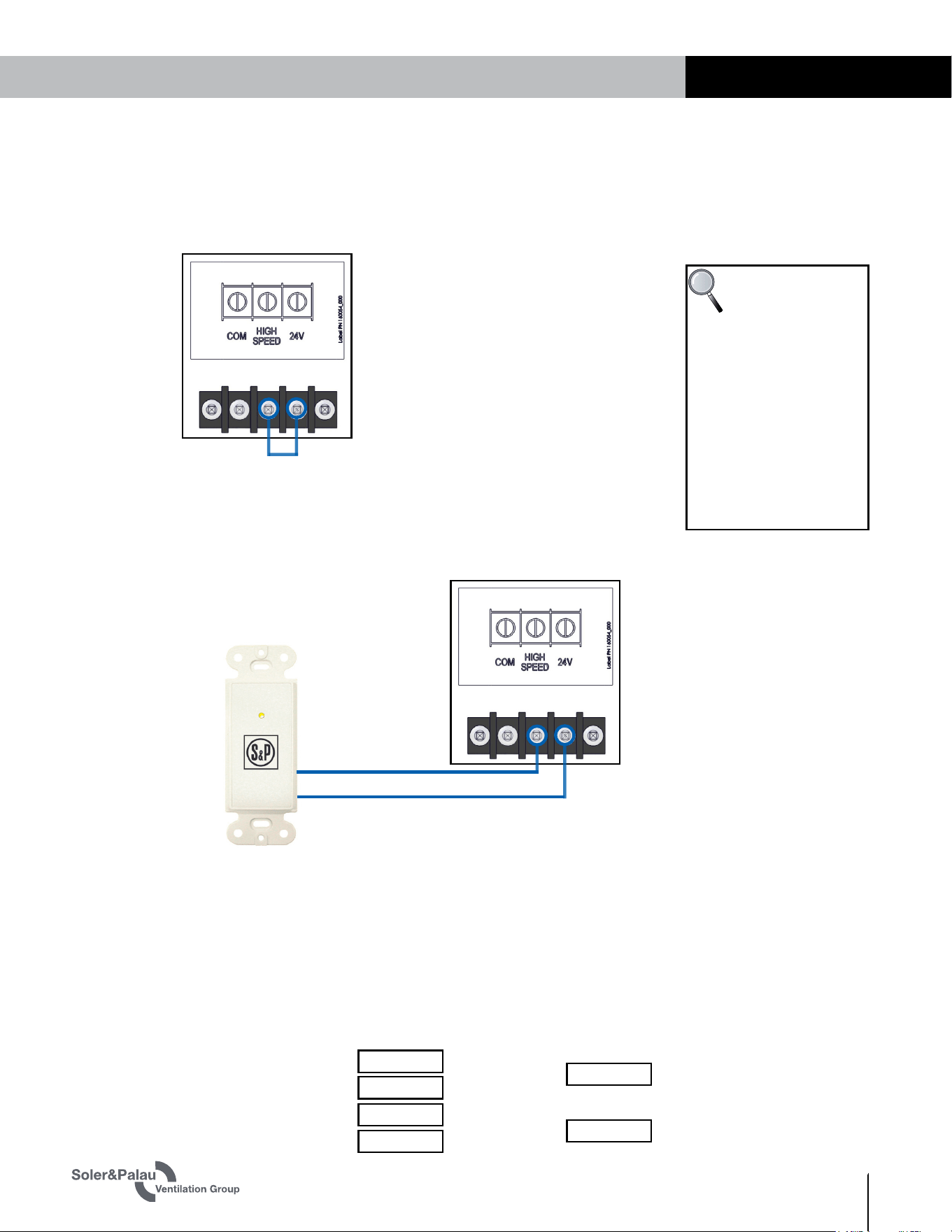
4.8 LOW VOLTAGE WIRING DIAGRAMS
4.8.1 Low Speed/High Speed Modes CONTINUOUS
When plugged in, the unit will run constantly at Low Speed. If the unit is to operate constantly
at High Speed, a jumper wire must be installed between the High Speed terminal and the 24
VAC terminal as well.
4.8.2 Low Speed CONTINUOUS/High Speed SWITCHED
If the TRe is to run constantly at Low Speed (Continuous mode or Off) and then switch
periodically to Boost mode in response to a controlling device. The external controlling device,
such as a SPBT control or an occupancy sensor that is to trigger Boost mode (High Speed), is
connected to the 24 VAC terminal and to the High Speed terminal.
NOTE: Occupancy
sensors have a
total of six wires.
The two NO (Normally
Open) contact wires would
connect to the 24 VAC and
High Speed terminals. The
sensor’s 24 VAC power
wires would connect to the
COM and 24 VAC terminals
on the terminal strip. This
wiring configuration will
vary with each control
sensor.
5.0 OPERATION
5.1 MANOMETER READINGS AT COMMISSIONING
Return Air Pressure Port In. w.g.:
Exhaust Air Pressure Port In. w.g.:
Outside Air Pressure Port In. w.g.:
Supply Air Pressure Port In. w.g.:
Pressure Drop:
Pressure Drop:
FIGURE 4.8.0 LOW VOLTAGE WIRING DIAGRAM 1
FOR CONSTANT HIGH SPEED CONTINUOUS
OPERATION, INSTALL A JUMPER WIRE FROM
THE 24 VAC TERMINAL TO THE HIGH SPEED
TERMINAL.
If multiple controls are desired to operate the unit in Boost mode for different purposes, they
may be wired in parallel. The unit control board provides 6 VA so the combined power demand
for desired accessories must be lower than this threshold. For example, a SPBT controller
may be wired to an TRe unit and up to 6 SPBL controls may be wired in parallel. For additional
information see the installation manuals for the control(s) you select for wiring diagrams and
specific instructions.
FIGURE 4.8.1 LOW VOLTAGE WIRING DIAGRAM 2
NORMALLY OPEN
CONTACT WIRE
NORMALLY OPEN
CONTACT WIRE
TRe-Series
ERV
WWW.SOLERPALAU-USA.COM INSTALLATION, OPERATION AND MAINTENANCE MANUAL 1.800.961.7370
16
MAINTENANCE
6.0 MAINTENANCE
This unit is only to be
used after completion of
building construction. It
is not to be used during
construction.
IMPORTANT
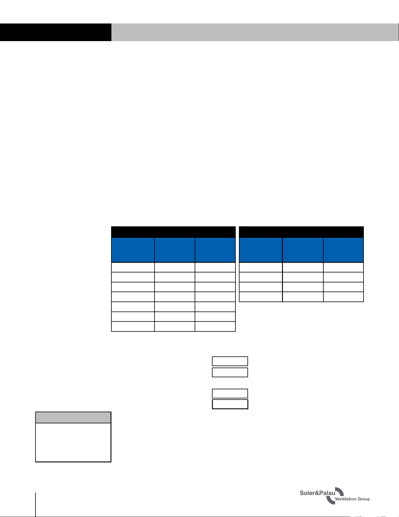
5.2 AIRFLOW READINGS AT COMMISSIONING
5.2.1 Conversion of Pressure Drop to Airflow
See the tables below.
(Units equipped with clean MERV 8 filters.)
To determine the airflow in CFM, obtain the manometer readings shown above and calculate the
differences between them. Then apply the following formula to convert the readings to CFM:
TRe200: [Airflow in CFM] = 283 x [Core Pressure Drop in inches w.g.]
TRe300: [Airflow in CFM] = 593 x [Core Pressure Drop in inches w.g.]
EXAMPLE: 1 In. w.g. of pressure drop across the core corresponds to 283 CFM, 0.5 In. w.g.
corresponds to 141.5 CFM, and so on for the TRe200.
(Units equipped with a MERV 13 filter in the OA airstream. Formulas below are for OA airstream
only.)
TRe200: [Airflow in CFM] = 235 x [Core Pressure Drop in inches w.g.]
TRe300: [Airflow in CFM] = 487 x [Core Pressure Drop in inches w.g.]
EXAMPLE: 1 In. w.g. of pressure drop across the core corresponds to 235 CFM of airflow. So
1 In. w.g. of pressure drop across the core corresponds to 235 CFM, 0.5 In. w.g. corresponds to
117.5 CFM, and so on for the TRe200.
FIGURE 5.2.0 PRESSURE DROP TO AIRFLOW CONVERSIONS
TRE200
Core Pressure
Drop (In.
W.G.)
Airflow with
MERV 8
Filters (CFM)
Airflow with
MERV 13
Filters (CFM)
0.1 28 24
0.2 57 47
0.3 85 71
0.4 113 94
0.5 142 118
0.6 170 141
0.7 198 165
TRE300
Core Pressure
Drop (In.
W.G.)
Airflow with
MERV 8
Filters (CFM)
Airflow with
MERV 13
Filters (CFM)
0.1 59 49
0.2 119 97
0.3 178 146
0.4 237 195
Outdoor Airflow: CFM
Return Airflow: CFM
Outdoor Airflow: CFM
Return Airflow: CFM
5.2.2 Continuous Mode (low speed)
5.2.3 Boost Mode (high speed)
The primary maintenance requirement is filter replacement. Filters are not to be cleaned, they
must be replaced. The standard filter as shipped from the factory is a mesh-type, anti-microbial
MERV 8. These standard filters are NOT to be sprayed with filter treatments or dust adhesives.
The standard mesh-type OA MERV 8 filters may be replaced with pleated paper MERV 13 filters
post-construction, if desired. Both filters should be replaced every three months, or more
frequently, if needed.
TRe-Series ERV
17
1.800.961.7370 INSTALLATION, OPERATION AND MAINTENANCE MANUAL WWW.SOLERPALAU-USA.COM
MAINTENANCE
6.1 MAINTENANCE AFTER 30 DAYS OPERATION
6.2 RECALIBRATION OF AIRFLOWS
After 30 days of unit operation, check/tighten all mounting and support hardware. Inspect
filters for cleanliness. There is often construction dust collected during initial operation. If filters
appear dirty, replace them.
Whenever there is a reconfiguration of the heating system in a residence, to include changing
damper positions, the fan speed potentiometers on the TRe should be re-calibrated for optimum
performance. If the residence undergoes significant structural changes, such as an addition
to the home, the TRe should also be re-calibrated. If optional MERV 13 filters are installed,
recalibration is also required.
6.3 DOOR REMOVAL
The hinged door is held in place by two separable hinges on one edge and two security latches
on the other edge. The separable hinges have a spring-loaded detent to prevent accidental
separation. To remove the door, first disconnect power to the unit. Unlatch and open the door
and then strike the edge of the door, pushing the door toward the OA/EA side of the unit.
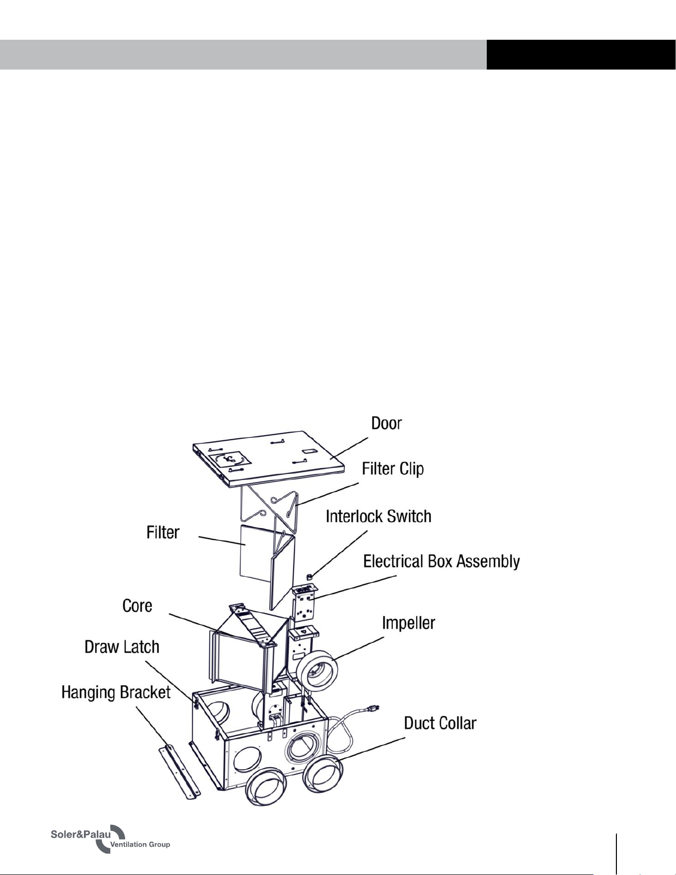
6.4 SERVICE PARTS
F
IGURE 6.4.0 TRe SERVICE PARTS
The enthalpic core should be vacuumed annually. Remove the hinged access door by sliding it
horizontally on its pin hinges and then remove the filters for access to the core. Use a soft-
bristled nozzle on a good vacuum and carefully vacuum the inlet faces of the core.
Ducts should be inspected annually. Ensure all ducts and joints are free from damage,
contaminants, or leaks in order for the system to behave properly.
TRe-Series
ERV
WWW.SOLERPALAU-USA.COM INSTALLATION, OPERATION AND MAINTENANCE MANUAL 1.800.961.7370
18
TROUBLESHOOTING
7.0 TROUBLESHOOTING
7.1 INDICATION OF PROBLEM
Many of the troubleshoot-
ing steps described herein
require working with or
near live high-voltage.
Take appropriate pre-
cautions against electric
shock and use Personal
Protective Equipment (PPE)
as a safeguard. Wear
gloves, safety glasses and
protective head gear, as
necessary.
CAUTION
Indications of a problem with the ERV may be the perception that Fresh Air is not being
delivered. The first step in resolving an apparent problem with an TRe ERV is to verify that there
actually is a problem.
Regardless of the reason for thinking there is a problem with the TRe, the first steps in
troubleshooting are to check the air filters to make sure they’re clean and properly positioned,
and then do a hard restart of the unit. A hard restart involves unplugging the unit for several
seconds and then plugging it back in. It takes a few moments for the control board to discharge.
After reapplying power, check to see if resetting the circuit has solved the problem.
Because there are many different ways of ducting the Supply Air into a dwelling, it’s often
difficult to say with certainty that the fresh air provided by the TRe is not reaching its intended
destination or if the ERV is simply no longer providing enough fresh air. Determine where and
how the fresh air is supposed to be delivered—if it is being carried in a dedicated duct directly
to the air outlet, check for airflow at the outlet.
u
Verify that dampers are still correctly positioned (open). If the ERV is being ducted into a main
air handling system, shut the air handling system down so that airflow at the ducts can be
detected.
u
Check for airflow at the air openings nearest to the TRe, not at the far end of the house. It
may be necessary to hold a thin strip of tissue paper in front of a vent to realize whether or
not there is airflow.
u
Check for airflow in both low speed and high speed settings. It will be easier to detect airflow
in the high speed setting.
u
Check ducts and duct runs and problems with bends, sagging, etc.
7.
2 TRe HAS AIRFLOW BUT IS MAKING NOISE
Feel the TRe while it is running to see if there is excessive vibration from the fans. Fan noise
and vibration can be caused by an imbalance in the rotors or possibly by a bad bearing. Turn off
power to the unit and rotate the fan impellers by hand. Make sure impellers rotate freely. Use
wet swabs to clean any dust/dirt buildup off the impeller blades. If problem continues, a fan
may have a bad bearing.
7.3 NO APPARENT AIRFLOW FROM THE TRe
If it seems that there is no apparent airflow, verify that it has power.
u
If it does not have power, trace the power supply back to its source and isolate the problem
or symptoms. Look for a switch turned off, a blown fuse or a tripped circuit breaker. If
necessary, use a multimeter to trace the power supply and isolate the problem.
u
If it has power and the fans will not run, disconnect all power to the unit and check the
disconnect switch with an ohmmeter.
u
If it has power, check to see if the fans are running by listening for fan noise and feeling the
unit for vibration from the fans.
u
If it has power and the fans are running, CHECK THE FILTERS TO MAKE SURE THEY ARE
CLEAN. Check the entire length of the ducts, all the way from the outdoor vent hoods to the
indoor vent openings. Make sure a duct has not fallen off or that a flexible duct has not been
pinched. In rare cases, there may be obstructions inside the duct. Look to see if a louver in
an outdoor vent cap is stuck or blocked or if an indoor louver has been shut.
u
If it has power but only one fan is running, disconnect all power to the unit and check the fan
connectors to make sure they are still making contact.

TRe-Series ERV
19
1.800.961.7370 INSTALLATION, OPERATION AND MAINTENANCE MANUAL WWW.SOLERPALAU-USA.COM
FACTORY ASSISTANCE
7.4 INADEQUATE OR REDUCED AIRFLOW FROM THE TRE
If the unit has power and both fans are running, use a manometer to check the pressure
differential across the core. See Section 6.3 Using a Manometer in this manual. The results of
a pressure differential test will provide correct information on how much air the unit is moving
and also how the volume of air compares to when the unit was first installed. Check both low
speed and high speed settings by changing the jumpers on the low voltage terminal strip, as
shown in section 4.8 in this manual. Check ducts for bends, blockages, or leaks.
7.5 TRE FAILS TO RUN IN EITHER LOW SPEED OR HIGH SPEED MODE
The low-speed and high-speed modes operate independently of each other so there can be a
failure in just one mode and it does not appear in the second mode. If one mode does not work,
the problem can be isolated to either the controlling device or to an internal failure by bypassing
the controlling device.
u
Remove all wiring from the terminal strip as shown in Section 4.8 of this manual. Mark the
wires so they can be reconnected in their proper locations.
u
With no jumper present, check for proper operation.
u
Install a jumper wire from the 24 VAC terminal to the High Speed terminal. Check for proper
operation. Remove the jumper wire and reinstall the control device wiring.
7.6 NO APPARENT REASON FOR LOW AIRFLOW
The final step in troubleshooting an ERV problem is to reset the fan potentiometers. Use a
manometer and follow the instructions in Section 6.3 Using a Manometer in this manual.
Restore the pressure differential settings to their original airflow settings (CFM), as recorded in
Section 5.1.

141153_000 (10/20)
USA
(800) 961-7370
FAX: (800) 961-7379
6393 POWERS AVE
JACKSONVILLE, FLORIDA
32217 USA
WWW.SOLERPALAU-USA.COM
CANADA
(416) 744-1217
FAX: (416) 744-0887
6710 MARITZ DRIVE, UNIT 7
MISSISSAUGA, ON L5W 0A1, CANADA
WWW.SOLERPALAUCANADA.COM