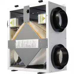
TRCe500
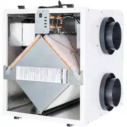
TRCe800
TRCe800V
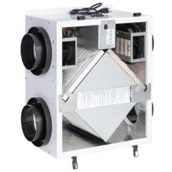
TRCe1200
EC Motor Supplemental Manual
Supplemental Manual for Options
Model Shown: TRCe1200
Model Shown: TRCe500
Model Shown: TRCe800 Model Shown: TRCe800V
WWW.SOLERPALAU-USA.COM
EC Motors
OPTIONS
2
WWW.SOLERPALAU-USA.COM EC MOTOR SUPPLEMENTAL MANUAL 1.800.961.7370
WARNING
RISK OF FIRE, ELECTRIC SHOCK, OR INJURY. OBSERVE ALL CODES AND THE FOLLOWING:
1. Before servicing or cleaning the unit, switch power off at disconnect switch or service
panel and lockout/tag-out to prevent power from being switched on accidentally. More
than one disconnect switch may be required to de-energize the equipment for servicing.
2. This installation manual shows the suggested installation method. Additional measures
may be required by local codes an standards.
3. Installation work and electrical wiring must be done by qualified professional(s) in
accordance with all applicable codes, standards and licensing requirements.
4. Any structural alterations necessary for installation must comply with all applicable
building, health, and safety code requirements.
5. This unit must be grounded.
6. Sufficient air is needed for proper combustion and exhausting of gases through the flue
(chimney) of fuel burning equipment that might be installed in the area affected by this
equipment. If this unit is exhausting air from a space in which chimney vented fuel burning
equipment is located, take steps to assure that combustion air supply is not affected.
Follow the heating equipment manufacturer’s requirements and the combustion air supply
requirements of applicable codes and standards.
7. Use the unit only in the manner intended by the manufacturer. If you have questions,
contact the manufacturer.
8. This unit is intended for general ventilating only. Do not use to exhaust hazardous or
explosive materials and vapors. Do not connect this unit to range hoods, fume hoods, or
collection systems for toxics.
9. When cutting or drilling into wall or ceiling, do not damage electrical wiring and other
hidden utilities.
10. If installed indoors, this unit must be properly ducted to the outdoors.
CAUTION
When an external 10 VDC source control
is used, the maximum distance between
the EC Motor and 10 VDC source control
cannot exceed 33 ft (10 m).
CAUTION
To avoid motor bearing damage and noisy
and/or unbalanced impellers, keep drywall
spray, construction dust, etc., out of unit.
CAUTION
Very low airflow rates may result in fouling
of the energy exchanger core. Do not re-
duce airflow to below 250 cfm per core.
Make sure clean filters are installed before
balancing airflow. Dirty or clogged filters
reduce airflow through the unit.
CAUTION

EC Motors OPTIONS
3
1.800.961.7370 EC MOTOR SUPPLEMENTAL MANUAL WWW.SOLERPALAU-USA.COM
1.0 OVERVIEW 4
1.1 DESCRIPTION .......................................................................................................... 4
1.2 OPERATING CONTROLS ............................................................................................ 4
2.0 PERFORMANCE DATA 5
2.1 TRCE500 ECM OPERATING RANGE ........................................................................... 5
2.2 TRCE800 & TRCE800V ECM OPERATING RANGE ....................................................... 5
2.3 TRCE1200 ECM OPERATING RANGE ......................................................................... 6
3.0 INSTALLATION 7
3.1 PRINCIPLES OF EXTERNAL CONTROL 7
3.2 ELECTRICAL SPECIFICATIONS 7
3.3 WIRING SCHEMATICS............................................................................................... 8
3.3.1 TRCe500 ........................................................................................................................................ 8
3.3.2 TRCe800 and TRCe800V ................................................................................................................ 9
3.3.3 TRCe1200 .................................................................................................................................... 10
3.3.4 STC7D Field Wiring (Optional Accessory) ....................................................................................... 11
4.0 OPERATION 12
4.1 AIRFLOW PERFORMANCE ...................................................................................... 12
4.2 MEASURING AIRFLOW ........................................................................................... 12
4.2.1 Equipment Required ...................................................................................................................... 12
4.2.2 Cross Core Static Pressure Measurement Instructions ................................................................... 12
4.3 AIRFLOW VERSUS PRESSURE DROPS ..................................................................... 13
TABLE OF CONTENTS

EC Motors
OPTIONS
4
WWW.SOLERPALAU-USA.COM EC MOTOR SUPPLEMENTAL MANUAL 1.800.961.7370
1.0 OVERVIEW
S&P USA operations are based in Jacksonville, Florida. This geographically strategic location
allows the shipment of products throughout the U.S. and Canada. The Jacksonville
manufacturing facility has more than 150,000 square feet of warehouse space for the stocking
of a comprehensive range of products. This permits the overnight delivery of many popular
model sizes to anywhere in the U.S. and Canada.
At S&P USA we take pride in the fact that our customers receive only the very highest levels of
customer service and care. Our internal and external technical and customer service teams are
on-hand to provide professional and experienced application advice to enable our customers
to apply our products to their particular ventilation and air movement applications. As the USA
sales, marketing and distribution division of the S&P Group of companies we are committed to
providing only the very highest levels of customer service. Our commitment in providing only
the very highest standards of customer service is key to our company strategy.
S&P Ventilation Group is the world’s leading fan manufacturer. It celebrated its 50th anniversary
in 2001. S&P is able to offer a range of ventilation products benefiting from over 50 years of
experience in the industry. The company’s impressive, long-term growth is the result of one
simple philosophy - develop an air moving product that effectively and efficiently meets the
needs of the customer, supported by unparalleled engineering, distribution and service.
In 1951 Eduard and Josep Palau, both born in Ripoll, Spain, founded the company Soler & Palau
(S&P). From the very start the business proved to be their vocation. Together they combined
their extensive knowledge and flair to ensure the successful start of their business project.
There is continual in-house product development with state-of-the-art technology, and a
continued program of in-house laboratory certifications.
Currently S&P’s R&D, manufacturing and distribution facilities occupy a total of 1.1 million
square feet, with offices and locations around the globe. S&P products can be found in virtu-
ally any commercial or residential application, ranging from innovative, quiet and reliable room
ventilators to large diameter, high capacity exhaust systems designed for critical applications in
some of the world’s toughest environments.
1.1 DESCRIPTION
S&P’s light commercial units are offered with optional electronically commutated motors
(ECM). ECM motors have higher efficiencies with considerable energy savings over a standard
permanent split capacitor motor. The ECM motors offered in S&P ERVs are constant torque with
a variety of speed control options. The motors operate at fixed speed or variable speed with
speed inputs from fixed resistors, potentiometer, or 0-10Vdc analog signal.
1.2 OPERATING CONTROLS
A wide variety of low voltage (24 VAC) control schemes may be selected to meet the ventilation
needs of the facility. These include time clock, occupancy sensor, carbon dioxide sensor, and
others. Building Management Systems (BMS) may also control the unit with external control by
others.
OVERVIEW
EC Motors OPTIONS
5
1.800.961.7370 EC MOTOR SUPPLEMENTAL MANUAL WWW.SOLERPALAU-USA.COM
2.0 PERFORMANCE DATA
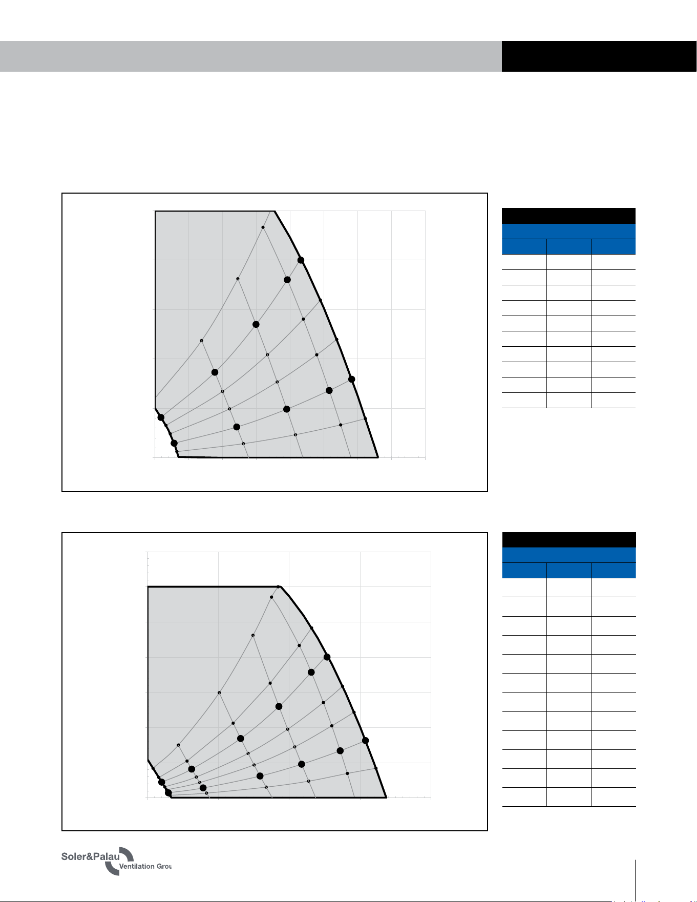
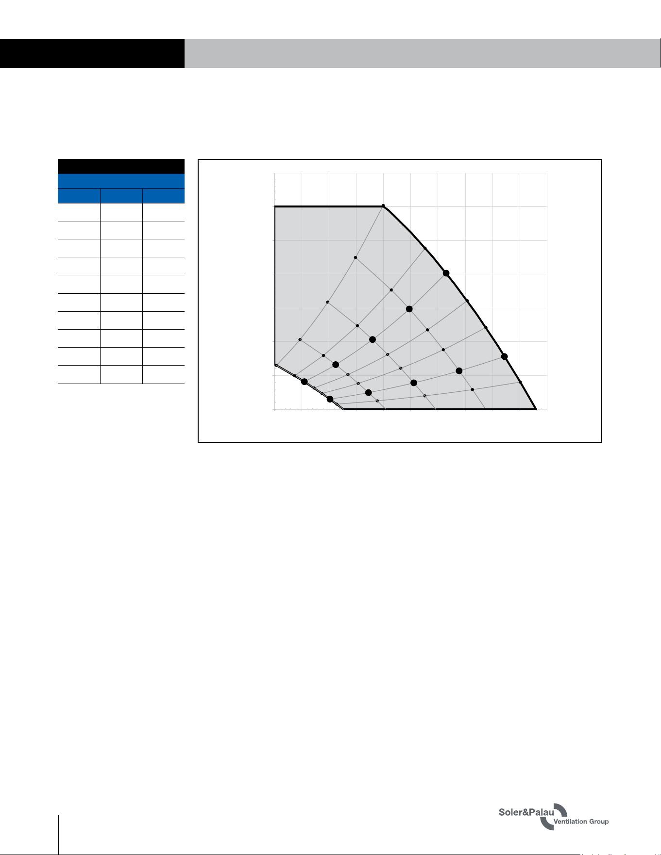
2.1 TRCE500 ECM OPERATING RANGE
0.00
0.25
0.50
0.75
1.00
1.25
200 250 300 350 400 450 500 550 600
External Static Pressure (in. w.g.)
Airflow (cfm)
EV450-IN ECM
74
75
76
80
80
160
171
177
183
188
198
269
284
299
307
315
328
403
410
427
436
447
449
500 (Watts)
506
520
521
515
487
TRCe500 ECM
Sample Points
CFM ESP* Watts
229 0.07 75
321 0.16 171
395 0.25 284
458 0.34 410
491 0.40 506
209 0.20 80
289 0.43 188
350 0.67 315
396 0.90 447
416 1.00 515
Note: Watts is for the entire unit.
*Inches Water Column
PERFORMANCE DATA
TRCe800 & TRCe800V ECM
Sample Points
CFM ESP* Watts
324 0.04 86
446 0.07 150
647 0.15 300
794 0.24 564
929 0.33 827
1019 0.41 1042
300 0.11 91
406 0.20 160
579 0.42 359
713 0.65 599
828 0.89 871
883 1.00 1075
Note: Watts is for the entire unit.
*Inches Water Column
2.2 TRCE800 & TRCE800V ECM OPERATING RANGE
0.00
0.25
0.50
0.75
1.00
1.25
1.50
1.75
250 500 750 1000 1250
External Static Pressure (in. w.g.)
Airflow (cfm)
HE1X-IN ECM (H or V)
85
97
89
148
150
153
156
160
164
173
273
300
322
340
359
386
392
560
564
572
583
599
643
655
818
827
839
852
871
911
918
1029 (Watts)
1042
1056
1068
1075
1029
992
EC Motors
OPTIONS
6
WWW.SOLERPALAU-USA.COM EC MOTOR SUPPLEMENTAL MANUAL 1.800.961.7370
PERFORMANCE DATA
2.3 TRCE1200 ECM OPERATING RANGE
TRCe1200 ECM
Sample Points
CFM ESP* Watts
630 0.07 189
807 0.12 314
1014 0.20 502
1222 0.28 735
1430 0.39 1015
513 0.20 185
656 0.33 310
825 0.52 498
994 0.74 735
1163 1.01 1017
Note: Watts is for the entire unit.
*Inches Water Column
0.00
0.25
0.50
0.75
1.00
1.25
1.50
1.75
375 500 625 750 875 1000 1125 1250 1375 1500 1625
External Static Pressure (in. w.g.)
Airflow (cfm)
HE1.5X-IN ECM
190
189
188
187
185
183
178
314
314
313
312
310
306
296
500
502
502
501
498
493
475
730
735
739
739
735
727
698
1006 (Watts)
1015
1021
1022
1017
1006
965
EC Motors OPTIONS
7
1.800.961.7370 EC MOTOR SUPPLEMENTAL MANUAL WWW.SOLERPALAU-USA.COM
INSTALLATION
3.0 INSTALLATION
3.1 PRINCIPLES OF EXTERNAL CONTROL
The light commercial units with EC motors are designed for control by a wide variety of low
voltage (24 VAC) controls to meet the ventilation needs of the facility. These include time clock,
occupancy sensor, carbon dioxide sensor, BMS, and others. These devices are commonly
known as 2-wire, 3-wire, and 4-wire devices. S&P offers separately the following for stand-
alone control of the ERV:
u Dig
ital Time Clock STC7D-W
u Occupancy Sensors SMC-C and SMC-W
u Carbon Dioxide Sensor/Controller SCO2-W
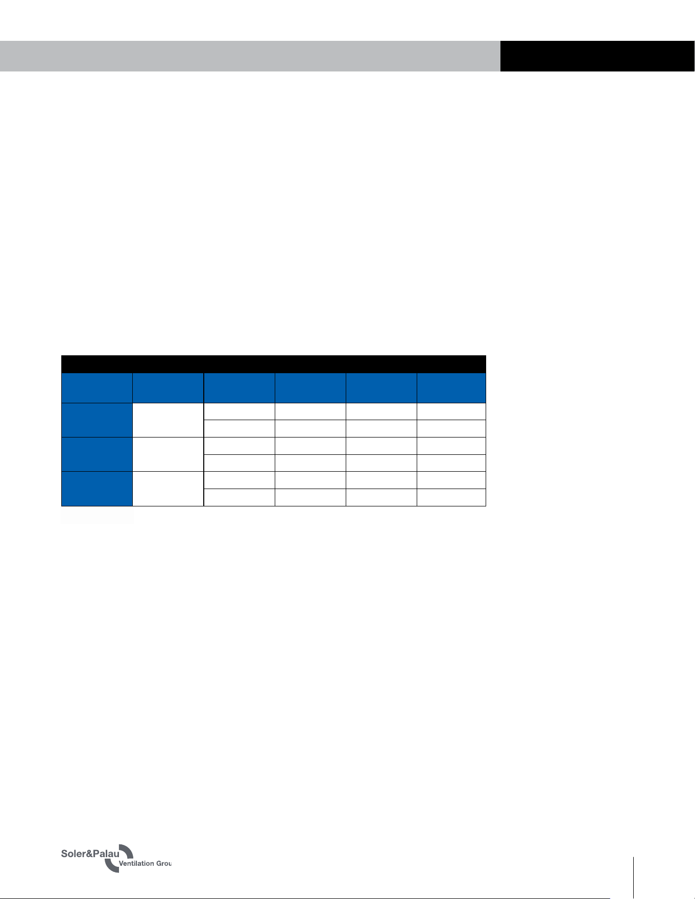
3.2 ELECTRICAL SPECIFICATIONS
Electrical Ratings for ECM Units
Phase (unit)
Input
Voltage
FLA
(motor)
MCA (unit) MOPD (unit)
TRCe500 1
115 VAC 8.1 10.1 15
208-230 VAC 4.8 6.0 15
TRCe800
TRCe800V
1
115 VAC 8.1 18.2 25
208-230 VAC 4.8 10.8 15
TRCe1200 1
115 VAC 8.0 18.0 20
208-230 VAC 4.4 9.9 15
EC Motors
OPTIONS
8
WWW.SOLERPALAU-USA.COM EC MOTOR SUPPLEMENTAL MANUAL 1.800.961.7370
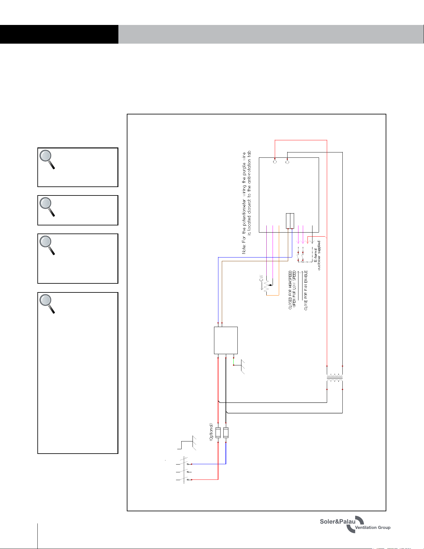
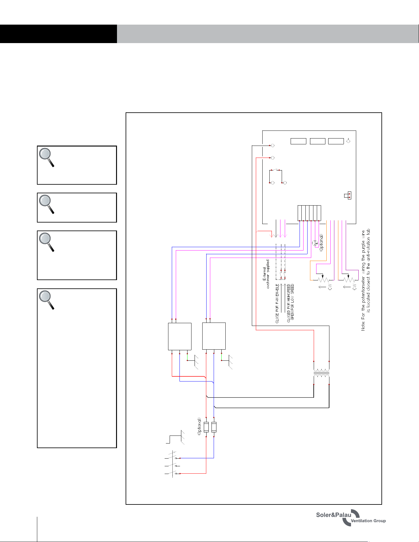
3.3 WIRING SCHEMATICS
3.3.1 TRCe500
INSTALLATION
CHANGESNAMEREV. DATE
Description
Family
Config
No Damper
RenewAire
1
ABCDE
New5 4/8/2020 austine
6
11/18/2020
NealW Updated potentiometer wiring and field 24 VAC
7
1/19/2021
NealW Changed transformer wire from BU to BK
EV450 ECM
2
3
4
5
6
7
8
9
10
11
12
13
EV450Jxx--x11,15-----GxTx-xx_007
24VAC
BK
RD
YL
YL
VAR
EN
24VAC
COM
Circuit Board
YL
PU
OR
GND
W
10V
COM
Input Power
115 VAC, 1 Phase
208-230 VAC, 1 Phase
GND
N/L3
L1
BR
BU
BK
BK
RD
L(L+)
N(L-)
GND
GND
0-10 V
4
5
SF ECM
BK
RD
XF1
BK
BURD
F1
1
2
R1
NOTE: Connect the
yellow EN wire to
the black COM wire
to enable the unit.
NOTE: By default
the resistors on the
board set SPEED 1.
NOTE: Connect the
yellow VAR wire to
the black COM wire
to enable SPEED 2. SPEED
2 is set by the
potentiometer.
NOTE: To utilize an
external 0–10 VDC
analog signal for
SPEED 2:
1. Remove the potentiom-
eter by cutting the wires at
the potentiometer.
2. Connect the remote
analog signal to the yellow
wire from the
potentiometer.
3. Connect the remote
signal ground to the purple
wire from the
potentiometer.
4. Cap the orange wire
from the potentiometer
with a wire nut.
EC Motors OPTIONS
9
1.800.961.7370 EC MOTOR SUPPLEMENTAL MANUAL WWW.SOLERPALAU-USA.COM
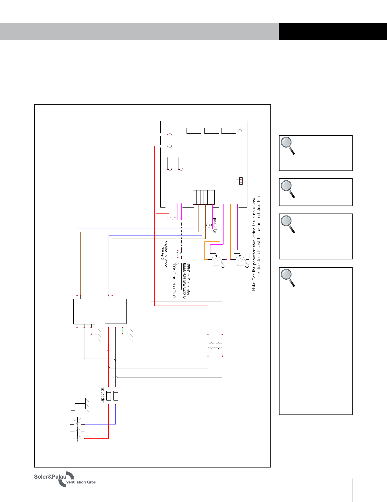
INSTALLATION
3.3.2 TRCe800 and TRCe800V
CHANGESNAMEREV. DATE
Description
Family
Config
No Damper
RenewAire
1
ABCDE
New4 3/26/2020 austine
5
11/6/2020
NealW Updated potentiometer wiring and field 24 VAC
6
1/18/2021
NealW Updated 24 VAC Com wire color
HE-1XIN ECM
2
3
4
5
6
7
8
9
10
11
12
13
HE-1XJINx-x11,15xx---GxTx-xx_006
1
2
3
4
1
2
3
4
1
2
3
4
DOORKILL1
DOORKILL2
24VAC
BK
RD
YL
YL
VAR
EN
24VAC
COM
Circuit Board
J1
BYPASS
YL
PU
OR
YL
PU
OR
SFGND
SFW
SF10V
EFGND
EFW
EF10V
1
2
3
4
5
6
BYPASSCOM
EA/RA
OA/FA
COM
Input Power
115 VAC, 1 Phase
208-230 VAC, 1 Phase
GND
N/L3
L1
BR
BU
BK
BK
RD
L(L+)
N(L-)
GND
GND
0-10 V
4
5
SF ECM
BK
RD
XF1
BK
BURD
F1
L(L+)
N(L-)
GND
GND
0-10 V
4
5
EF ECM
SF EF
BR
BU
YL
YL
NOTE: Connect the
yellow EN wire to
the black COM wire
to enable the unit.
NOTE: By default
the resistors on the
board set SPEED 1.
NOTE: Connect the
yellow VAR wire to
the black COM wire
to enable SPEED 2. SPEED
2 for each fan is set by the
potentiometers.
NOTE: To utilize an
external 0–10 VDC
analog signal for
SPEED 2:
1. Remove the potentiom-
eter by cutting the wires at
the potentiometers.
2. Connect the remote
analog signal to the yellow
wire from the
potentiometers.
3. Connect the remote
signal ground to the purple
wire from the
potentiometers.
4. Cap the orange wire
from the potentiometers
with a wire nut.
EC Motors
OPTIONS
10
WWW.SOLERPALAU-USA.COM EC MOTOR SUPPLEMENTAL MANUAL 1.800.961.7370
INSTALLATION
3.3.3 TRCe1200
CHANGESNAMEREV. DATE
Description
Family
Config
No Damper
RenewAire
1
ABCDE
New4 3/26/2020 austine
5
11/5/2020
NealW Updated potentiometer wiring and Field 24 VAC
6
1/18/2021
NealW Added 277 VAC
7
2/4/2021
NealW Updated wire colors
HE1.5X ECM
2
3
4
5
6
7
8
9
10
11
12
13
HE-1.5XJxxx-x11,15,19xx---GxTx-xx_007
1
2
3
4
1
2
3
4
1
2
3
4
DOORKILL1
DOORKILL2
24VAC
BK
RD
YL
YL
VAR
EN
24VAC
COM
Circuit Board
J1
BYPASS
YL
PU
OR
YL
PU
OR
SFGND
SFW
SF10V
EFGND
EFW
EF10V
1
2
3
4
5
6
BYPASSCOM
EA/RA
OA/FA
COM
Input Power
115 VAC, 1 Phase
208-230 VAC, 1 Phase
GND
N/L3
L1
YL
BU
BK
BU
RD
L(L+)
N(L-)
GND
GND
0-10 V
4
5
SF ECM
BK
RD
XF1
BK
BURD
F1
L(L+)
N(L-)
GND
GND
0-10 V
4
5
EF ECM
SF
EF
YL
YL
YL
BU
NOTE: Connect the
yellow EN wire to
the black COM wire
to enable the unit.
NOTE: By default
the resistors on the
board set SPEED 1.
NOTE: Connect the
yellow VAR wire to
the black COM wire
to enable SPEED 2. SPEED
2 for each fan is set by the
potentiometer.
NOTE: To utilize an
external 0–10 VDC
analog signal for
SPEED 2:
1. Remove the potentiom-
eter by cutting the wires at
the potentiometer.
2. Connect the remote
analog signal to the yellow
wire from the
potentiometer.
3. Connect the remote
signal ground to the purple
wire from the
potentiometer.
4. Cap the orange wire
from the potentiometers
with a wire nut.
EC Motors OPTIONS
11
1.800.961.7370 EC MOTOR SUPPLEMENTAL MANUAL WWW.SOLERPALAU-USA.COM
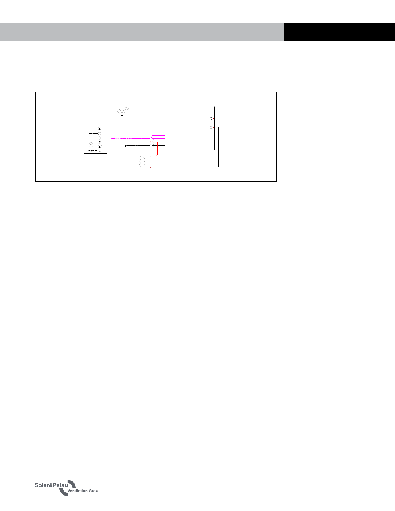
INSTALLATION
CHANGESNAMEREV. DATE
Description
Family
Config
Field Wiring
RenewAire
1
ABCDE
EV450 ECM
2
3
4
5
6
7
8
9
10
11
12
13
EV450Jxx--x11,15-----GxTx-xx_006
24VAC
BK
RD
YL
YL
VAR
EN
24VAC
COM
Circuit Board
YL
PU
OR
GND
W
10V
COM
BK
RD
XF2
1
2
R2
3.3.4 STC7D Field Wiring (Optional Accessory)
EC Motors
OPTIONS
12
WWW.SOLERPALAU-USA.COM EC MOTOR SUPPLEMENTAL MANUAL 1.800.961.7370
4.0 OPERATION
4.1 AIRFLOW PERFORMANCE
The ERV is factory wired to operate at low fixed speed and variable speed.
Airflows must be measured and the unit’s potentiometers adjusted so that it operates at the
airflow volumes specified for the installation.
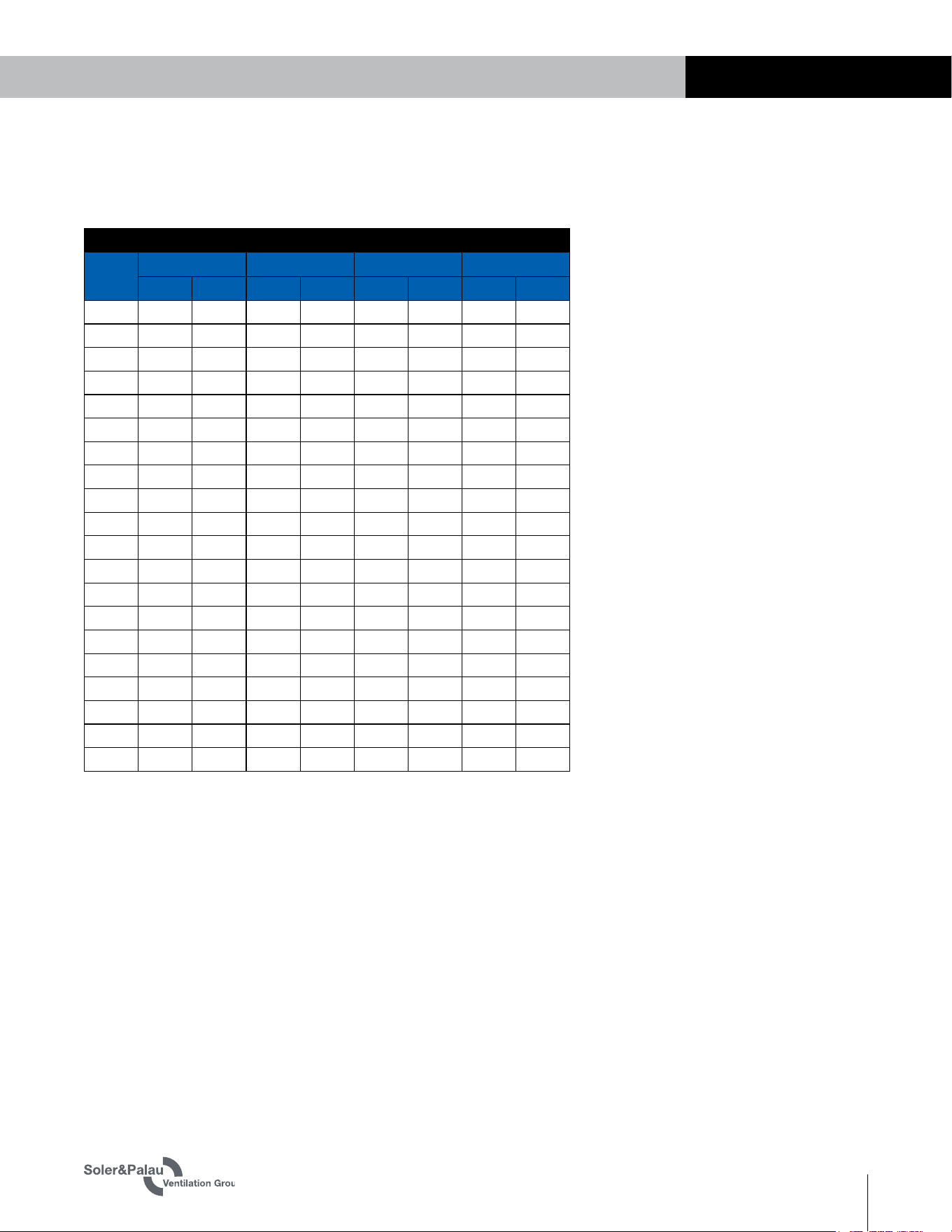
Use the pressure taps in the core and filter doors to determine the airflow. Section 4.3
translates the pressure drop across the energy recovery core to the actual airflow volume.
4.2 MEASURING AIRFLOW
4.2.1 Equipment Required
u
Magnehelic gauge or other device capable of measuring 0–1.5 in. water of
differential pressure.
u
2 pieces of flexible tubing, 1/8" ID, 1/16" wall works best.
4.2.2 Cross Core Static Pressure Measurement Instructions
u
The individual differential pressures (DP) are measured using the installed pressure ports
located in the front of the units core access doors.
u
To read SCFM of Fresh Air (FA) install the “high” pressure side (+) of your measuring device
to the Outside Air (OA) port and the “low” pressure side (-) to the Fresh Air (FA) port.
u
To read SCFM of Room Air (RA) install the “high” pressure side (+) of your measuring device
to the Room Air (RA) port and the “low” pressure side (-) to the Exhaust Air (EA) port.
u
Use the reading displayed on your measurement device to cross reference the CFM output
using the conversion chart.
u
Adjust airflow by changing the potentiometer setting for the measured airstream.
NOTE: Be sure to
remove cap from
pressure port before
inserting tubing. Ensure
tubing is well seated in
pressure ports.
NOTE: The tubing
should extend in
the pressure port
approximately 1".
NOTE: These ports
are carefully located
on the unit to give
the most accurate airflow
measurement. Do not
relocate ports.
NOTE: Be sure to
replace cap into
pressure port when
airflow measuring is
complete.
NOTE: For best
performance the
airflow rate for
both the FA and EA should
be roughly equal (“bal-
anced”). In some facil-
ities a slight positive or
negative pressure in the
building is desired. S&P
energy recovery ventilators
can generally operate with
a flow imbalance of up to
20% without significant
loss in energy recovery
efficiency.
OPERATION
EC Motors OPTIONS
13
1.800.961.7370 EC MOTOR SUPPLEMENTAL MANUAL WWW.SOLERPALAU-USA.COM
AIRFLOW PREDICTED BY PRESSURE DROP ACROSS CORE (SCFM)
DP
("H
2
O)
TRCe500 ECM TRCe800V ECM TRCe800 ECM TRCe1200 ECM
FA RA FA RA FA RA FA RA
0.10 -- -- -- -- -- -- -- --
0.15 -- -- -- -- -- -- 380 320
0.20 200 200 280 -- 260 -- 500 440
0.25 225 225 330 270 310 290 620 565
0.30 245 245 380 320 360 340 740 695
0.35 265 265 425 375 415 390 860 825
0.40 285 285 470 430 470 440 980 960
0.45 305 305 520 480 520 490 1095 1095
0.50 330 330 570 530 570 540 1215 1235
0.55 350 350 620 580 620 590 1330 1375
0.60 370 370 670 630 670 640 1450 1515
0.65 390 390 720 680 720 690 1565 --
0.70 410 410 770 730 770 740 -- --
0.75 430 430 815 785 820 790 -- --
0.80 455 455 860 840 870 840 -- --
0.85 475 475 910 890 920 890 -- --
0.90 495 495 960 940 970 940 -- --
0.95 -- -- 1010 990 1020 990 -- --
1.00 -- -- 1060 1040 1070 1040 -- --
1.05 -- -- -- 1090 -- 1090 -- --
4.3 AIRFLOW VERSUS PRESSURE DROPS
OPERATION

EC Motors
OPTIONS
14
WWW.SOLERPALAU-USA.COM EC MOTOR SUPPLEMENTAL MANUAL 1.800.961.7370
OPERATION
NOTES

EC Motors OPTIONS
15
1.800.961.7370 EC MOTOR SUPPLEMENTAL MANUAL WWW.SOLERPALAU-USA.COM
OPERATION
NOTES

S&P USA
(800) 961-7370
FAX: (800) 961-7379
6393 POWERS AVE.
JACKSONVILLE, FLORIDA
32217 USA
WWW.SOLERPALAU-USA.COM
S&P CANADA
(416) 744-1217
FAX: (416) 744-0887
6710 MARITZ DRIVE, UNIT 7
MISSISSAUGA, ON L5W 0A1, CANADA
WWW.SOLERPALAUCANADA.COM
104770_005 (06/21)