
Technical Support and E-Warranty Certificate www.vevor.com/support
SAND BLASTER CABINET
MODEL:SBC200
We continue to be committed to provide you tools with competitive price.
"Save Half", "Half Price" or any other similar expressions used by us only represents an
estimate of savings you might benefit from buying certain tools with us compared to the major
top brands and does not necessarily mean to cover all categories of tools offered by us. You
are kindly reminded to verify carefully when you are placing an order with us if you are
actually saving half in comparison with the top major brands.
- 1 -
MODEL:SBC200
Have product questions? Need technical support? Please feel free to
contact us:
Technical Support and E-Warranty Certificate
www.vevor.com/support
NEED HELP? CONTACT US!
This is the original instruction, please read all manual instructions
carefully before operating. VEVOR reserves a clear interpretation of our
user manual. The appearance of the product shall be subject to the
product you received. Please forgive us that we won't inform you again if
there are any technology or software updates on our product.
SAND BLASTER CABINET

- 2 -
IMPORTANT SAFETY INSTRUCTIONS
Instructions pertaining to a risk of fire, Electric shock, or injury to
persons
General
Warning-To reduce the risk of injury, user must read instructions
manual carefully.
When using tools, basic precautions should always be followed, including
the following:
Work Area
1. Keep the work area clean and well lighted. Cluttered benches and dark areas
increase the risks of electric shock, fire, and injury to persons.
2. Do not operate the tool in explosive atmospheres, such as in the presence
of flammable liquids,gases, or dust. The tool is able to create sparks resulting in
the ignition of the dust or fumes.
3. Keep bystanders, children, and visitors away while operating the tool.
Distractions are able to result in the loss of control of the tool.
Personal Safety
1. Stay alert. Watch what you are doing and use common sense when operating
the tool.Do not use the tool while tired or under the influence of drugs, alcohol, or
medication. A moment of inattention while operating the tool increases the risk of
injury to persons.
2. Dress properly. Do not wear loose clothing or jewelry. Contain long hair.Keep
hair, clothing, and gloves away from moving parts. Loose clothes, jewelry, or long
hair increases the risk of injury to persons as a result of being caught in moving
parts.
3. Avoid unintentional starting. Be sure the trigger is released before connecting to
the air supply. Do not connect the tool to the air supply with the switch on.
4. Do not overreach.

- 3 -
Keep proper footing and balance at all times.
Proper footing and balance enables better control of the tool in unexpected
situations.
Use safety equipment.A dust mask, non-skid safety shoes and a
hard hat must be used for the applicable conditions.
Always wear eye protection.
Wear ANSI-approved safety goggles.
Always wear hearing protection when using the tool.
Prolonged exposure to high intensity noise is able to cause hearing
loss.
Tool Use and Care
1. Use clamps or another practical way to secure and support the workpiece to a
stable platform.Holding the work by hand or against the body is unstable and is
able to lead to loss of control.
2. Do not force the tool. Use the correct tool for the application. The correct tool
will do the job better and safer at the rate for which the tool is designed.
3. Do not use the tool if the switch does not turn the tool on or off. Any tool that
cannot be controlled with the switch is dangerous and must be repaired.
4. Disconnect the tool from the air source before making any adjustments,
changing accessories, or storing the tool. Such preventive safety measures
reduce the risk of starting the tool unintentionally. Turn off and detach the air
supply, safely discharge any residual air pressure, and release the throttle and/or
turn the switch to its off position before leaving the work area.
5. Store the tool when it is idle out of reach of children and other untrained
persons. A tool is dangerous in the hands of untrained users.
6. Maintain the tool with care.
7. Check for misalignment or binding of moving parts, breakage of parts, and any

- 4 -
other condition that affects the tool's operation. If damaged,have the tool serviced
before using. Many accidents are caused by poorly maintained tools.
8. There is a risk of bursting if the tool is damaged.
9. Use only accessories that are identified by the manufacturer for the specific tool
model. Use of an accessory not intended for use with the specific tool model,
increases the risk of injury to persons.
Air Source
1. Never connect to an air source that is capable of exceeding 200 psi.
Over pressurizing the tool may cause bursting, abnormal
operation,breakage of the tool or serious injury to persons.Use
only clean, dry, regulated compressed air at the rated pressure
or within the rated pressure range as marked on the tool.
Always verify prior to using the tool that the air source has been
adjusted to the rated air pressure or within the rated air-pressure range.
2. Never use oxygen, carbon dioxide, combustible gases or any bottled
gas as an air source for the tool. Such gases are capable of explosion and
serious injury to persons.
Specific Safety Instructions
1. The warnings and precautions discussed in this manual cannot cover all
possible conditions and situations that may occur. It must be understood
by the operator that common sense and caution are factors which cannot be built
into this product,but must be supplied by the operator.
2. Obey the manual for the air compressor used to power this tool.
3. Install an in-line shutoff valve to allow immediate control over the air supply in an
emergency, even if a hose is ruptured.
Assembly Precautions
1. Assemble only according to these instructions. Improper assembly can create
hazards.

- 5 -
2. Wear ANSI-approved safety goggles and heavy-duty work gloves during
assembly.
3. Keep assembly area clean and well lit.
4. Keep bystanders out of the area during assembly.
5. Do not assemble when tired or when under the influence of drugs or medication.
Silicosis and Aluminum Oxide Warnings
WARNING! Abrasive blasting with sand containing crystalline silica can cause serious
or fatal respiratory disease. Exposure to crystalline silica may cause silicosis (a
serious lung disease), cancer and death. Exposure to aluminum oxide (a dust
generated from material removing processes) can result in eye, skin and breathing
irritation. Always use approved respirator and safety goggles. Avoid skin
exposure.Proper ventilation in the work area is required. Read and understand the
10 recommended measures below to reduce crystalline silica exposures in the
workplace and prevent silicosis and silicosis related deaths.
FUNCTIONAL DESCRIPTION
Specifications
Average Air Consumption
270 liter/min @ 6 bar
Maximum Working Pressure
40- 120 PSI
Air Inlet
1/4
″
NPT
Abrasive Capacity
+/- 18 kg
Dust Port
63 mm
Viewing Window
54 cm x 25 cm
Working Area (LxWxHmin-Hmax)
840 x 550 x 370-550mm
Dimensions (LxWxHmin-Hmax)
890 x 560 x 1118-1380mm
Included Nozzles
4.5mm, 5mm, 6mm, 7mm
- 6 -
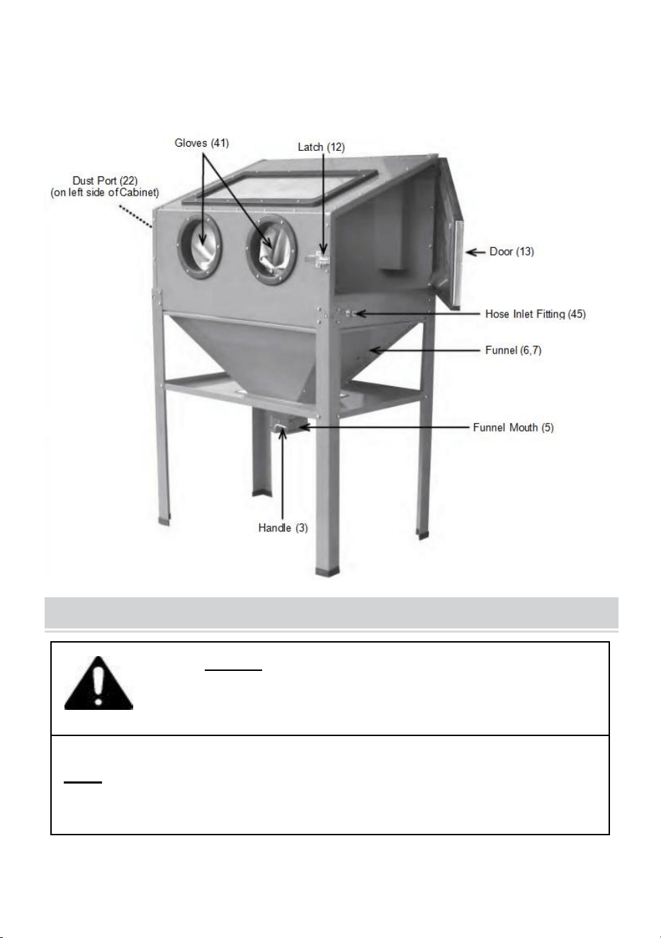
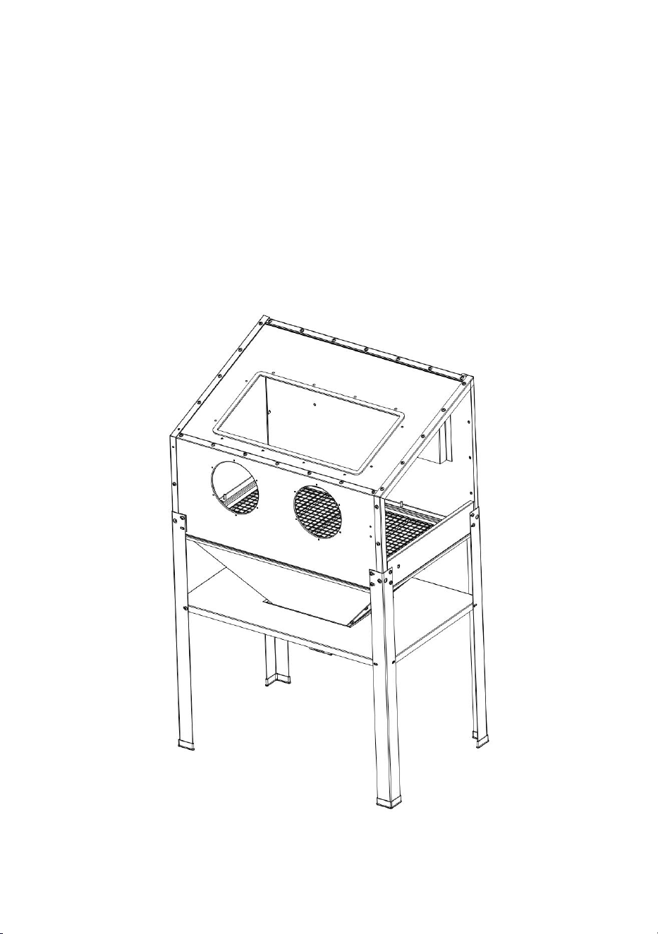
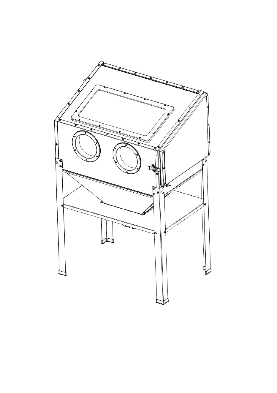
Components and Controls
Figure A: Components and Controls
INITIAL TOOL SET UP / ASSEMBLY
Read the ENTIRE IMPORTANT SAFETY INFORMATION section
at the beginning of this manual including all text under
subheadings therein before set up or use of this product.
Note: For additional information regarding the parts listed in the following pages,
refer to the Assembly Diagram near the end of this manual.
Note: This air tool may be shipped with a protective plug covering the air inlet.
Remove this plug before set up.
- 7 -
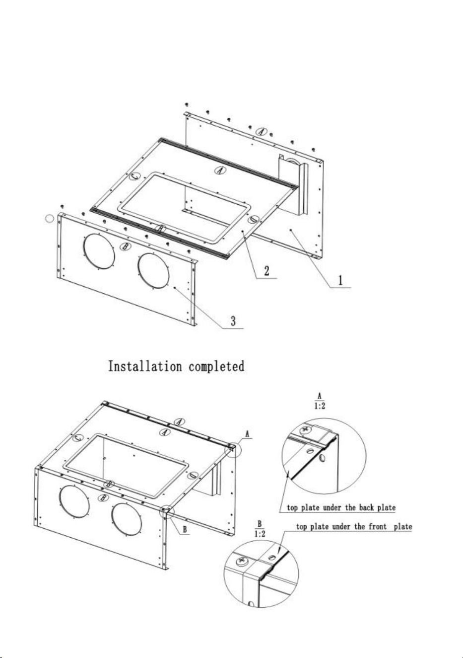
Assembly Steps
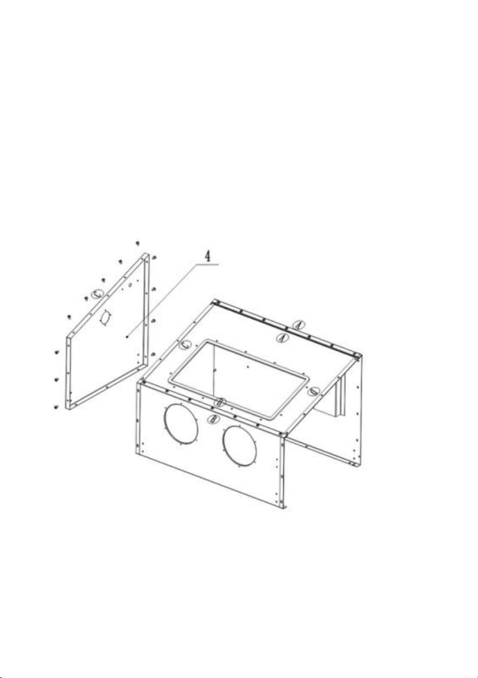
Step1. Assemble cabinet
- 8 -
1.Connect the window plate(No.2) with rear plate (No.1)by screw M6*12 ,
washer and nut. Please note the window plate should be under rear plate.
Pic. A.
2.Connect the front plate(No.3) with window plate by screw M6*12 ,
washer and nut. Please note the window plate should be under front plate.
Pic. B.
Note: When assemble window plate, please take care the direction,
A-A,B-B. The side with sealing foam should be upwards. The window
frame should be near front plate.
- 9 -
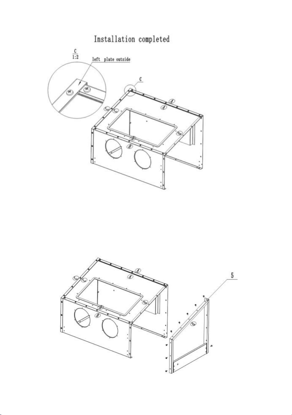
3. Cover the left plate(No.4) on the outside of rear plate, window plate and
front plate. Screw them with washer and nut M6*12. C-C
- 10 -
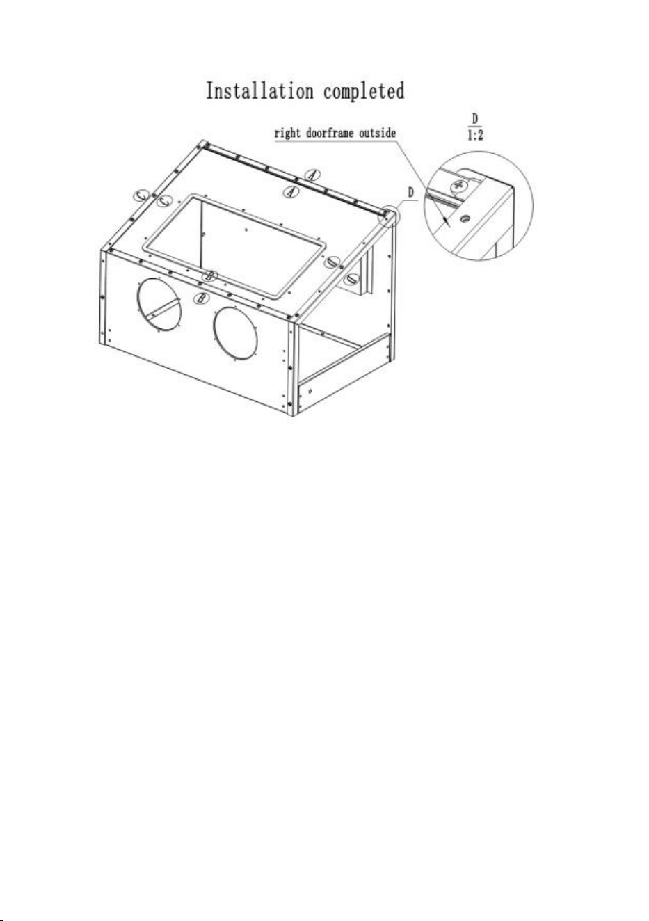
4. Cover the right plate(No.5) on the outside of rear plate, window plate
and front plate. Screw them with washer and nut M6*12. D-D
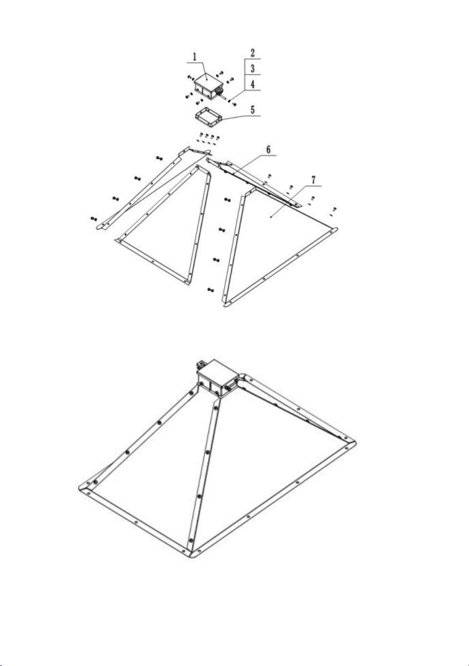
Step2. Assemble cabinet
- 11 -
- 12 -
1. Connect big funnel plate(No.7) with small funnel plate(No.6) by M6*8 pan head
screw(No.2),washer and flange nut(No.4). Wrap around the funnel mouth with
sealing foam (No.5) 2 circles. Fix the funnel box (No.1) with funnel by M6*12 pan
head screw and flange nut.
Note: the small funnel plate should be under big funnel plate.
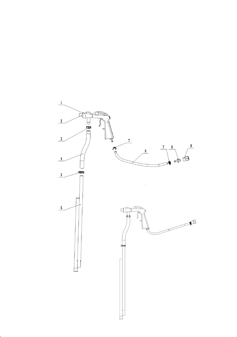
Step3 Assemble blasting gun
- 13 -
1.Connect sand hose (No.4) with gun(No.2), clamp (No.3)it.Connect sand pipe
(No.5) into sand hose and clamp it tightly.
2.Connect air hose (No.8) with gun and clamp(No.7) it. Then connect air connector
(No.6), inner thread connector(No.9). Please wrap 5 circles Teflon tape by
clockwise rotation on the air connector to avoid leakage.
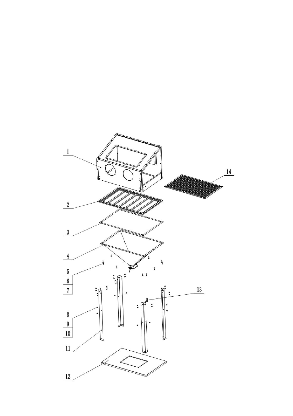
Step4 Assemble Body
- 14 -
1. Fix the full cabinet (Step 1) with the net frame(No.2), net washer (No.3), full
funnel (Step2) by screw M6*35(No.5), washer(No.6) and nut (No.7).
2. Fix the full cabinet (Step 1) with legs(No.11) by screw M6*12(No.8),
washer(No.9) and nut (No.10).
3. Connect the square board(No.12) by screw M6*12, washer and nut .
4. Put the net into cabinet.
Note: Insert a shim (No.13) when fix the leg and front plate. Insert the other two
shims again when fix the legs and rear plate.
- 15 -
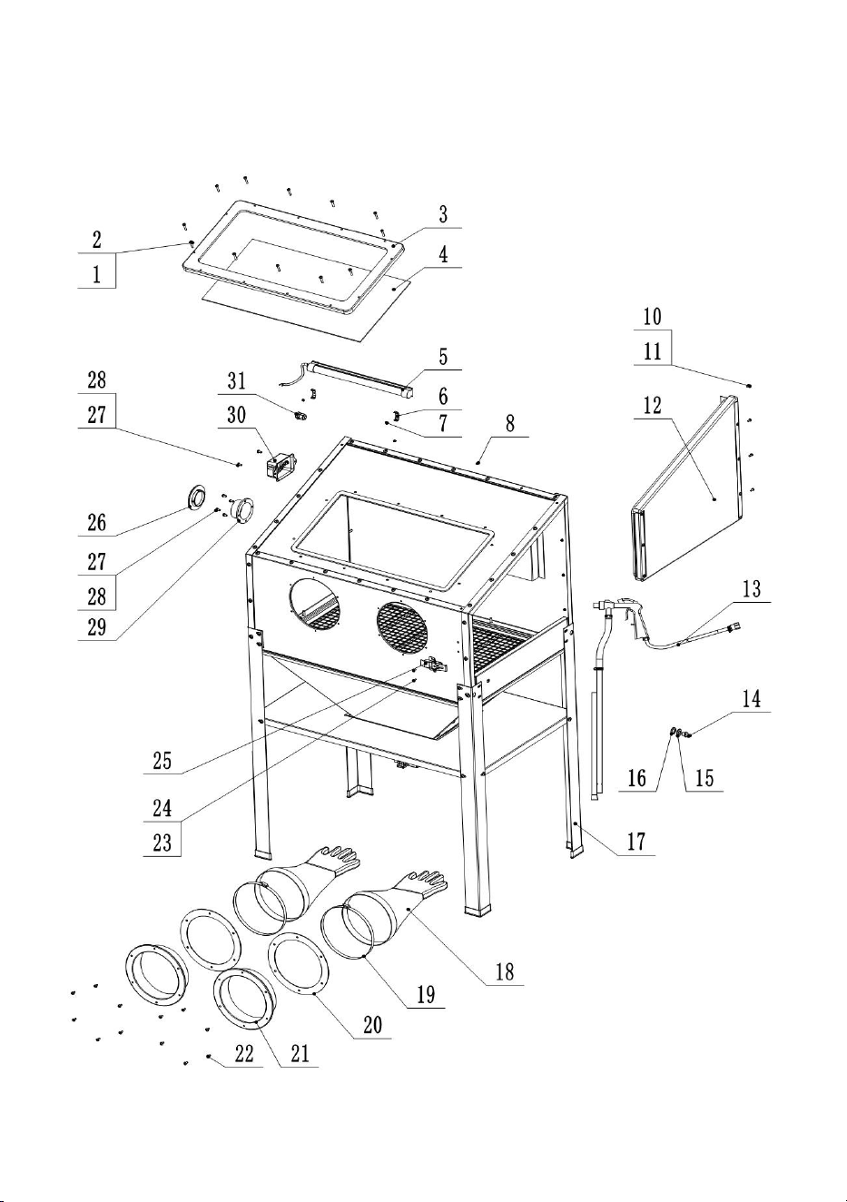
Step5 Assemble full machine

- 16 -
1. Install sandblasting gun assembly (Step3)(No.13) inside cabinet (No.17) , put
the metal washer (No.15) and rubber seal (No.16) to the air connector (No.14).
Then insert from hole of right cabinet plate and screw with inner thread connector.
Please note to wrap the Teflon tape for connector if necessary. To make sure no
air leakage.
2. Assemble the glove mounting ring(No.21)with big rubber seal ring (No.20) to
the front cabinet plate by ST4.8*14 screws (No.22). Fix the gloves(No.18) to the
plastic plastic edge and clamp (No.19)them tightly. It should be operated from
inside direction.
3. Install the door locker(No.25) in the front cabinet plate by M4*10 screw (No.24)
and nut(No.23).
4. Fix the lamp clips (No.7) to rear cabinet plate by M4*10 screw (No.8) and nut.
Lock the LED lamp(No.6) Put the lamp cable into the plastic sealing joint(No.31) ,
insert the joint into the hole of left cabinet plate and screw it tightly. Connect the
lamp cable to switch box(No.30) and fix the switch box on the cabinet by M5*10
screw (No.27) and nut(No.28).
5. Install the flange (No.29) by M5*10 screw (No.27) and nut(No.28) to left
cabinet plate. Block it by flange cover (No.26) if the machine is no working.
6. Assemble the right door to the cabinet by screw (No.11) and nut(No.12).
7.Put the plexiglass on the window plate (the side with PVC film should be
downwards). Cover the window frame(No.3) and fix with cabinet by screw M5*25
(No.1) and nut(No.2).
Important Notice:
1. Due to logistics reasons, few metal sheets may become slightly
deformed, which could to be corrected by simple tools. Normally it is
easily done. But please consult customer service if the correction is
still not in place after you try. Customer service staff will provide
proper solutions in time.
2. The sealing foam can be punctured with a screwdriver before
assembly to facilitate the installation of screws (the holes would be
hidden by sealing foam).
- 17 -

- 18 -
Parts list
Part
Description
Qty
1
Cross pan head screw M5*25
12
2
Hex flange nut M5
12
3
Window frame
1
4
Plexiglass with Protective Film
1
5
LED lamp
1
6
Lamp clip
2
7
Cross countersunk screw M4*6
2
8
Cross pan head screw M4*10
2
9
Silicone sealant
1
10
Cross pan head screwM4*10
4
11
Hex nut M4
4
12
Right door
1
13-1
Blasting gun +1 nozzle(Ø4.5)+1air connector
1
13-2
Air hose
1
13-4
Sand hose
1
13-5
Sand pipe
1
13-6
Hose clamp Ø16-Ø25
2
13-7
Hose clamp Ø8-Ø12
2
13-8
Inner thread connector 1/4”
1
14
Air connector 1/4-Ø6
1
15
Steel washer Ø13
1
16
Rubber washer Ø12.5
1
17
Leg with foot sleeve
4
18
Glove
2
19
Glove clamp
2
20
Glove seal
r
ing
2
21
Glove m ounting ring
2

- 19 -
22
Tapping screw o f glove ring ST 4 . 8 x 1 4
12
23
Cross pan head screw M4*10
2
24
Hex nut M4
2
25
Door latch
1
26
Dust Collector Port Cover
1
27
Cross pan head screw M5*10
4
28
Hex nut M5
4
29
Dust collector flange
1
30
Switch box
1
30-1
Cross pan head screw M5*10
2
30-2
Hex nut M5
2
31
Plastic sealing joint
1
32
Hinge pre-assembled on Door (13) M4x10
1
33
PVC protective Film
3
34
Leg Shim
3
35
Transformer
1
36
PTFE Teflon tape
1
37
Nozzle Ø5,6,7
3
38
Sealing foam 760MM
1
39
Manual
1

- 20 -
Air Supply
TO PREVENT SERIOUS INJURY FROM EXPLOSION:
Use only clean, dry, regulated, compressed air to power this tool.
Do not use oxygen, carbon dioxide, combustible gases, or any other bottled gas as
a power source for this tool.
1.Incorporate a filter, regulator with pressure gauge, dryer, in-line shutoff valve, and
quick coupler for best service, as shown on Figure L on page 12 and Figure M on
page 13. An in-line shutoff ball valve is an important safety device because it
controls the air supply even if the air hose is ruptured. The shutoff valve should be a
ball valve because it can be closed quickly.
Note: An oiler system should not be used with this tool. The oil will mix with the
material being propelled, causing tool to clog.
2. Attach an air hose to the compressor's air outlet. Connect the air hose to the air
inlet of the tool. Other components, such as a coupler plug and quick coupler, will
make operation more efficient, but are not required.
WARNING! TO PREVENT SERIOUS INJURY FROM ACCIDENTAL OPERATION:
1. Do not install a female quick coupler on the tool.Such a coupler contains an air
valve that will allow the air tool to retain pressure and operate accidentally after the
air supply is disconnected.
Note: Air flow, and therefore tool performance, can be hindered by undersized air
supply components.The air hose must belong enough to reach the work area with
enough extra length to allow free movement while working.
2. Turn the tool's throttle or switch to the off position; refer to Operation section for
description of controls.
3. Close the in-line shutoff valve between the compressor and the tool.
4. Turn on the air compressor according to the manufacturer's directions and allow
it to build up pressure until it cycles off.
5. 6. Adjust the air compressor's output regulator so that the air output
is enough to properly power the tool, but the output will not exceed the
tool's maximum air pressure at any time. Adjust the pressure gradually,
while checking the air output gauge to set the right pressure range.
6. Inspect the air connections for leaks. Repair any leaks found.
7. If the tool will not be used at this time, turn off and detach the air supply, safely

- 21 -
discharge any residual air pressure, and release the throttle and/or turn the switch
to its off position to prevent accidental operation.
Note: Residual air pressure should not be present after the tool is disconnected
from the air supply. However, it is a good safety measure to attempt to discharge
the tool in a safe fashion after disconnecting to ensure that the tool is disconnected
and not powered.
OPERATING INSTRUCTIONS
Read the ENTIRE IMPORTANT SAFETY INFORMATION section at the beginning
of this manual including all text under subheadings therein before set up or use of
this product.Inspect tool before use, looking for damaged, loose, and missing parts.
If any problems are found, do not use tool until repaired.
Tool Set Up
TO PREVENT SERIOUS INJURY FROM ACCIDENTAL OPERATION:
Turn off the tool, detach the air supply, safely discharge any residual air pressure
in the tool, and release the trigger before performing any inspection, maintenance,
or cleaning procedures.
TO PREVENT SERIOUS INJURY:
Do not adjust or tamper with any control or component in a way not specifically
explained within this manual. Improper adjustment can result in tool failure or other
serious hazards.
1. Remove the Dust Port Cover (29) on the left side of the Cabinet and install a
dust collection system (sold separately) to the Dust Port opening to remove media
dust while blasting.
2. If not using a dust collection system, check that the Dust Port Cover is in place
over the Dust Port opening on the left side of the Cabinet.
3. Fill the bottom of the Cabinet with no more than 40 pounds of fine
abrasive material. Fill the funnel area about 1/2 full. To prevent clogging,
do not overfill. Do not use harsh abrasive media, such as steel shot or
aluminum oxide.
WARNING! Do not use sand or abrasives that contain crystalline silica. Abrasive
blasting with sand containing crystalline silica can cause serious or fatal
respiratory disease. See ″Silicosis and Aluminum Oxide Warnings″ .

- 22 -
General Operating Instructions
1. Connect the air compressor hose to the Hose Inlet Fitting.
2. Plug in and turn on the Cabinet light.
3. Turn on the vacuum of the dust collection system (sold separately).
Note: When using a vacuum dust collector, clean the filter periodically to maintain
adequate suction and effectiveness of the vacuum.
4. Open the Door of the Blast Cabinet and place the workpiece in the center of the
Cabinet.
5. Close the door and secure the latch.
6. Set the compressor s air pressure between 6 and 8 bar.
7. Place your hands into the Gloves inside the Cabinet. Make sure your fingers
are in the proper positions and that you can easily move your hands and grip
objects.
8. Hold the workpiece in one hand, positioning your fingers so that the glove is not
in the way of the area you will be blasting. While working, reposition your grip as
needed to ensure that all areas of the workpiece will be contacted with the blast
material.
9. Grip the Abrasive Gun with the other hand and point the nozzle at the bottom of
the Cabinet.
10. Squeeze the trigger.
11. Check that the abrasive media is flowing through the suction hose with no
leaks. Release the trigger and correct any leaks if needed.
12. Otherwise begin blasting the workpiece.
WARNING! Do not aim the nozzle at your fingers or the Blast Gloves. If Gloves
are punctured or you feel air blowing in the Glove, replace them immediately.
Do not use a damaged or punctured Glove.
13. If the tool requires more force to accomplish the task,verify that the tool
receives sufficient, unobstructed airflow (CFM) and increase the pressure (PSI)
output of the regulator up to the maximum air pressure rating of this tool.
CAUTION! TO PREVENT INJURY FROM
TOOL OR ACCESSORY FAILURE:
Do not exceed the tool's maximum air pressure rating.

- 23 -
If the tool still does not have sufficient force at maximum pressure and sufficient
airflow,then a larger tool may be required.
14. When finished, or to check the progress of your blasting:
a. Release the trigger, lay the workpiece on the floor of the Cabinet and remove
your hands from the gloves.
b. Turn off the compressor and dust collection system (if equipped). Wait for the air
inside the Cabinet to clear.
c. Open the Cabinet door and remove the workpiece. If the workpiece needs more
blasting, resume from step 4 of these operating instructions.
15. To prevent accidents, release the trigger, detach the air supply, then squeeze
and release the trigger once more to safely discharge any residual air pressure in
the tool. Empty the Funnel of blast media (see User-Maintenance Instructions
section). Clean external surfaces of the tool with a clean, dry cloth.
Then store the tool indoors out of children's reach.
Cleaning, Maintenance, and Lubrication
Note: These procedures are in addition to the regular checks and maintenance
explained as part of the regular operation of the air-operated tool.
1. Daily - Air Supply Maintenance:
Everyday, maintain the air supply according to the component manufacturers'
instructions. Drain the moisture filter regularly. Performing routine air supply
maintenance will allow the tool to operate more safely and will also reduce wear on
the tool.
2. After use, empty the Cabinet Funnel of blast media:
CAUTION! Wear ANSI-approved Safety Goggles and NIOSH-approved dust
mask/respirator when emptying the abrasive media.
a. Place a container (sold separately), which is large enough to holdall the blast
media, under the mouth of the Funnel.
b. Turn the handle on the Funnel Mouth to open the Funnel and allow all the
abrasive media to flow into the container.
c. Close the Funnel Mouth.

- 24 -
Troubleshooting
Problem
Possible Causes
Likely Solutions
Decreased
output.
1. Not enough air
pressure and/ or air flow.
2. Obstructed trigger.
3. Blocked air inlet screen
(if equipped).
4. Air leaking from loose
housing.
5. Mechanism
contaminated.
6. Abrasive media level
too low.
7. Lubrication being used.
1. Check for loose connections
and make sure that air supply is
providing enough air flow (l/min) at
required pressure (bar) to the
tool's air inlet. Do not exceed
maximum air pressure.
2. Clean around trigger to ensure
free movement.
3. Clean air inlet screen of buildup.
4. Make sure housing is properly
assembled and tight.
5. Have qualified technician clean
and lubricate mechanism. Install
in-line filter in air supply as stated
in Setup: Air Supply.
6. Add more abrasive media to the
Funnel.
7. An oiler system should not be
used with this cabinet. The oil will
mix with the material being
propelled, causing gun to clog.
Housing
heats
during use.
Worn parts.
Have qualified technician inspect
internal mechanism and replace
parts as needed.
Severe air
leakage.
(Slight air
leakage
is normal,
especially
on older
1. Cross-threaded
housing components.
2. Loose housing.
3. Damaged valve or
housing.
4. Dirty, worn or
damaged valve.
1. Check for incorrect alignment
and uneven gaps. If
cross-threaded, disassemble and
replace damaged parts before
use.
2. Tighten housing assembly. If
housing cannot tighten properly,

- 25 -
tools.)
internal parts may be misaligned.
3. Replace damaged components.
4. Clean or replace valve
assembly.
Abrasive
media not
effective.
Abrasive media has
become worn down from
use.
Replace abrasive media.
Abrasive
media does
not fire
from
Abrasive
Gun.
1. Lubrication being
used.
2. Abrasive media size is
too large for Nozzle.
3. Abrasive media too
moist and is sticking
together.
1. An oiler system should not be
used with this tool. The oil will mix
with the material being propelled,
causing gun to clog.
2. Replace Nozzle with a nozzle
large enough to handle abrasive
media size or use finer media.
3. Replace media with dry, fresh
media.
Incorporate an air drier on the air
supply.
Light inside
Cabinet
does not
work.
1. Bulb is burned out.
2. Power cord is not
plugged in.
3. Switch is off.
4. Outlet is
non-functioning.
1. Replace light bulb.
2. Check that the power cord is
properly
plugged into an outlet.
3. Turn the Light Power Switch on.
4. Have electrical outlet serviced
by a qualified electrician.
Follow all safety precautions whenever diagnosing or servicing the tool.
Disconnect air supply before service.
PARTS LIST AND DIAGRAM
Please read the following carefully the manufacturer and/or distributor has

- 26 -
provided the parts list and assembly diagram in this manual as a reference tool
only. Neither the manufacturer or distributor makes any representation or warranty
of any kind to the buyer that he or she is qualified to make any repairs to the
product, or that he or she is qualified to replace any parts of the product. In fact,
the manufacturer and/or distributor expressly states that all repairs and parts
replacements should be undertaken by certified and Licensed technicians, and not
by the buyer. The buyer assumes all risk and liability arising out of his or her
repairs to the original product or replacement parts
Thereto, or arising out of his or her installation of replacement parts thereto.

- 27 -
FCC Information
CAUTION: Changes or modifications not expressly approved by the party
responsible for compliance could void the user's authority to operate the
equipment!
This device complies with Part 15 of the FCC Rules. Operation is subject to the
following two conditions:
1) This product may cause harmful interference.
2)This product must accept any interference received, including interference that
may cause undesired operation.
WARNING: Changes or modifications to this product not expressly approved by
the party.responsible for compliance could void the user's authority to operate the
product.
Note: This product has been tested and found to comply with the limits for a Class
B digital device pursuant to Part 15 of the FCC Rules, These limits are designed to
provide reasonable protection against harmful interference in a residential
installation.
This product generates, uses and can radiate radio frequency energy, and if not
installed and used in accordance with the instructions, may cause harmful
interference to radio communications. However, there is no guarantee that
interference will not occur in a particular installation. If this product does cause
harmful interference to radio or television reception,which can be determined by
turning the product off and on, the user is encouraged to try to correct the
interference by one or more of the following measures.
· Reorient or relocate the receiving antenna.
· Increase the distance between the product and receiver.
· Connect the product to an outlet on a circuit different from that to which the
receiver is connected.
· Consult the dealer or an experienced radio/TV technician for assistance.

- 28 -
CORRECT DISPOSAL
This product is subject to the provision of european Directive
2012/19/EU. The symbol showing a wheelie bin crossed through
indicates that the product requires separate refuse collection in the
European Union. This applies to the product and all accessories
marked with this symbol. Products marked as such may not be
discarded with normal domestic waste, but must be taken to a
collection point for recycling electrical and electronic devices.
Address:Shuangchenglu 803nong11hao1602A-1609shi, baoshanqu,
shanghai 200000 CN.
Imported to AUS: SIHAO PTY LTD. 1 ROKEVA STREETEASTWOOD
NSW 2122 Australia
Imported to USA: Sanven Technology Ltd. Suite 250, 9166 Anaheim
Place, Rancho Cucamonga, CA 91730
REP
UK
YH CONSULTING LIMITED.
C/O YH Consulting Limited Office 147,
Centurion House, London Road,
Staines-upon-Thames, Surrey, TW18 4AX
REP
EC
E-CrossStu GmbH.
Mainzer Landstr.69, 60329 Frankfurt am Main.