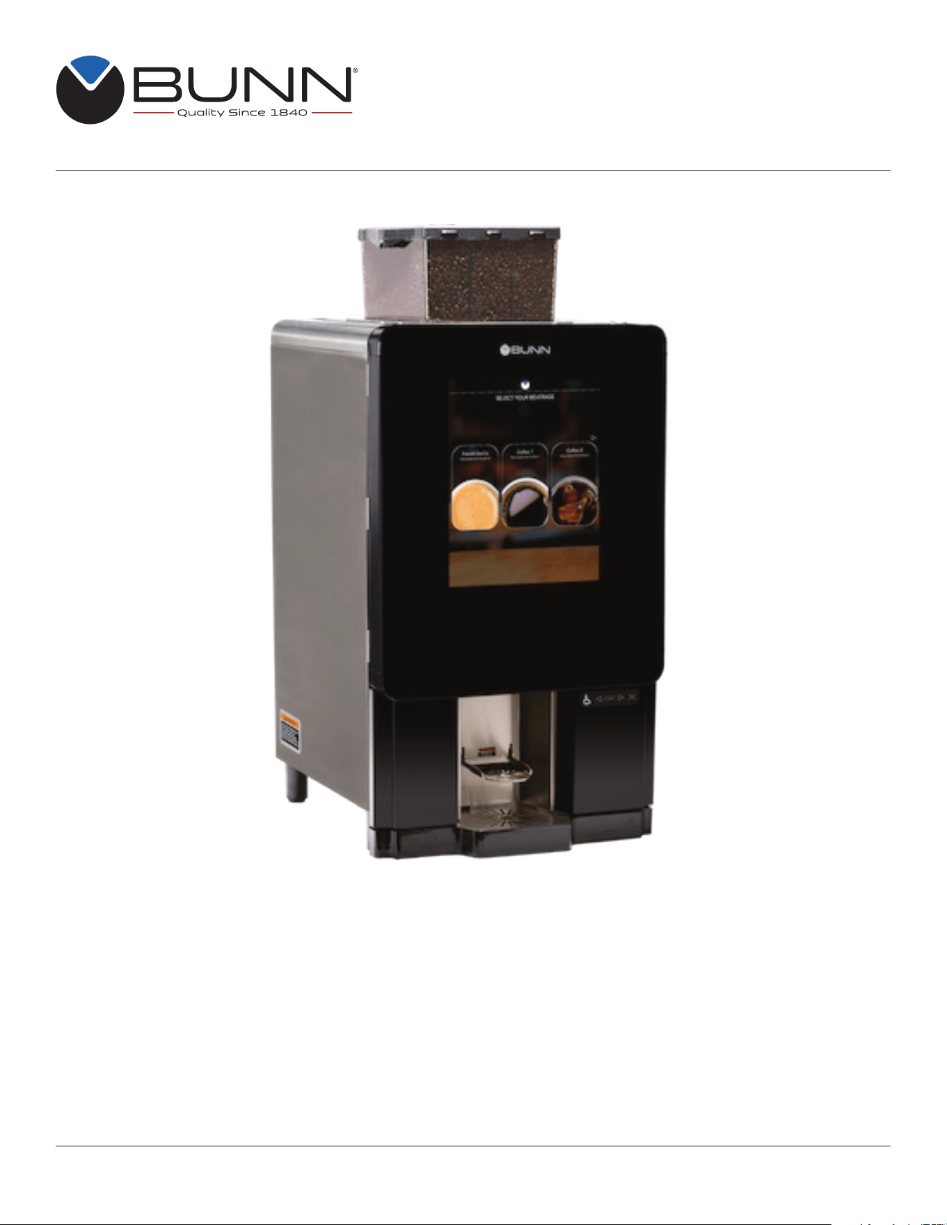
Sure Immersion
®
312
Bean to Cup Coffee System
Bunn-O-Matic Corporation
Post Office Box 3227, Springfield, Illinois 62708-3227
Phone (217) 529-6601 | Fax (217) 529-6644
INSTALLATION & OPERATING GUIDE
For Technical Service, contact Bunn-O-Matic Corporation at 1-800-286-6070.
53565.0001 J 05/25 © 2018 - 2025 Bunn-O-Matic Corporation www.bunn.com

2
BUNN-O-MATIC COMMERCIAL PRODUCT WARRANTY
Bunn-O-Matic Corp. (“BUNN”) warrants the BUNN Sure Immersion
®
system as further described below for a warranty
period of 1 year parts and labor.
For customers subscribed to BUNNlink
®
, BUNN reserves the right to periodically auto-push critical software updates
that will enhance functionality or performance of the BUNN equipment, unless the customer requests advance notice
of such software updates from BUNN in writing.
These warranty periods run from the date of installation. BUNN warrants that the equipment manufactured by it will
be commercially free of defects in material and workmanship existing at the time of manufacture and appearing within
the applicable warranty period. This warranty does not apply to any equipment, component or part that was not manu-
factured by BUNN or that, in BUNN’s judgment, has been affected by misuse, neglect, alteration, improper installation
or operation, improper maintenance or repair, non periodic cleaning and descaling, equipment failures related to poor
water quality, damage or casualty. This warranty is conditioned on the Buyer 1) giving BUNN prompt notice of any claim
to be made under this warranty by telephone at (217) 529-6601 or by writing to Post Office Box 3227, Springfield,
Illinois 62708-3227; 2) if requested by BUNN, shipping the defective equipment prepaid to an authorized BUNN service
location; and 3) receiving prior authorization from BUNN that the defective equipment is under warranty. Additionally, the
following is excluded from the warranty period:
Warranty Exclusions:
• Parts such as, but not limited to, hoppers and lids, drip trays, and plastic parts damaged due to improper handling
or cleaning agents.
• Replacement of wear items such as, but not limited to, O-rings, gaskets, tubes, brew box seal, hoses,
and valve seats.
• Repairs made necessary due to poor water quality, such as dispense valves, coils, water inlet valves,
scaling in hot water boilers.
• Improper voltage, (See equipment operations manual for voltage specifications).
• Touch screen due to improper use or damage.
• Failure to perform cleaning procedures constitutes improper maintenance.
• Failure to have required preventive maintenance performed by a BUNN technician or an authorized
BUNN service agent.
• Parts replaced under the terms of this warranty carry the remainder of the machine’s parts warranty term,
or 60 days, whichever is greater.
THE FOREGOING WARRANTY IS EXCLUSIVE AND IS IN LIEU OF ANY OTHER WARRANTY, WRITTEN OR
ORAL, EXPRESS OR IMPLIED, INCLUDING, BUT NOT LIMITED TO, ANY IMPLIED WARRANTY OF EITHER
MERCHANTABILITY OR FITNESS FOR A PARTICULAR PURPOSE. The agents, dealers or employees of BUNN
are not authorized to make modifications to this warranty or to make additional warranties that are binding on BUNN.
Accordingly, statements by such individuals, whether oral or written, do not constitute warranties and should not be
relied upon.
If BUNN determines in its sole discretion that the equipment does not conform to the warranty, BUNN, at its exclusive
option while the equipment is under warranty, shall either 1) provide at no charge replacement parts and/or labor
(during the applicable parts and labor warranty periods specified above) to repair the defective components, provided
that this repair is done by a BUNN Authorized Service Representative; or 2) shall replace the equipment or refund the
purchase price for the equipment.
THE BUYER’S REMEDY AGAINST BUNN FOR THE BREACH OF ANY OBLIGATION ARISING OUT OF THE
SALE OF THIS EQUIPMENT, WHETHER DERIVED FROM WARRANTY OR OTHERWISE, SHALL BE LIMITED, AT
BUNN’S SOLE OPTION AS SPECIFIED HEREIN, TO REPAIR, REPLACEMENT OR REFUND.
In no event shall BUNN be liable for any other damage or loss, including, but not limited to, lost profits, lost sales, loss
of use of equipment, claims of Buyer’s customers, cost of capital, cost of down time, cost of substitute equipment,
facilities or services, or any other special, incidental or consequential damages.

3
CONTENTS
BUNN-O-MATIC COMMERCIAL PRODUCT WARRANTY ......................................................................................2
NORTH AMERICAN REQUIREMENTS .................................................................................................................... 4
CE REQUIREMENTS ................................................................................................................................................4
USER NOTICES ........................................................................................................................................................ 5
LOCATIONS OF SERIAL NUMBER .......................................................................................................................... 5
SUPPORT .................................................................................................................................................................5
SITE REQUIREMENTS .............................................................................................................................................6
Counter Top Installation .......................................................................................................................................6
Counter Requirements .........................................................................................................................................6
INITIAL SETUP .........................................................................................................................................................6
Plumbing ...............................................................................................................................................................6
Location of the Serial Number .............................................................................................................................. 6
Water Treatment ...................................................................................................................................................6
Configuration ........................................................................................................................................................7
Electrical Hook-Up ................................................................................................................................................7
120-208/240V MODELS ............................................................................................................................................ 7
Bean Hopper Setup ..............................................................................................................................................8
Powder Hopper Setup ........................................................................................................................................ 10
Waste Bin / Drip Tray .......................................................................................................................................... 11
Filter Paper Installation ....................................................................................................................................... 12
BUNNLINK ACTIVATION ........................................................................................................................................ 13
Ethernet WI-FI Board Activation ......................................................................................................................... 13
OPERATING INTERFACE ....................................................................................................................................... 19
ADA Interface ..................................................................................................................................................... 21
ADA Visually Impaired Interface ......................................................................................................................... 23
VIRTUALTOUCH OPERATION ...............................................................................................................................26
Screen Ordering Lockout....................................................................................................................................27
OPTIONAL CASHLESS PAYMENT SYSTEM ......................................................................................................... 28
BARCODE PRINTER SETUP .................................................................................................................................29
Automatically ......................................................................................................................................................29
Manually .............................................................................................................................................................30
Clear Barcode Number .................................................................................................................................. 30
Setting Beverage Prices ................................................................................................................................31
Set Print Fields ..............................................................................................................................................32
Export Settings ..............................................................................................................................................32
Print Settings .................................................................................................................................................33
Print Last Receipt ..........................................................................................................................................33
FILTER PAPER REMOVAL .....................................................................................................................................34
FILTER PAPER REPLACEMENT ............................................................................................................................ 36
SERVICE ACCESS .................................................................................................................................................38
Paper Advance Function ....................................................................................................................................38
Clean Screen Function .......................................................................................................................................38
Care and Cleaning ..............................................................................................................................................39
Daily ....................................................................................................................................................................39
Parts Washing ...............................................................................................................................................39
Rinse Tab .......................................................................................................................................................39
Rinse Tab .......................................................................................................................................................40
Weekly ................................................................................................................................................................40
Clean Tab ......................................................................................................................................................40
Cleaning Tablets ............................................................................................................................................ 41
Cleaning Touch Panel ....................................................................................................................................42
Brew Funnel ...................................................................................................................................................43
Mixing Chamber Parts Cleaning .................................................................................................................... 45
Preventive Maintenance ................................................................................................................................45
Active Notices ..................................................................................................................................................... 46
Notice History .....................................................................................................................................................46
Customer Care Alerts ......................................................................................................................................... 47

4
NORTH AMERICAN REQUIREMENTS
CE REQUIREMENTS
• This appliance must be installed in locations where it can be overseen by trained personnel.
• For proper operation, this appliance must be installed where the temperature is between 41°F to 95°F (5°C to 35°C).
• Appliance shall not be tilted more than 10° for safe operation.
• An electrician must provide electrical service as specified in conformance with all local and national codes.
• This appliance must not be cleaned by pressure washer.
• This appliance can be used by persons if they have been given supervision or instruction concerning use of the
appliance in a safe way and if they understand the hazards involved.
• Keep the appliance and its cord out of reach of children.
• Appliances can be used by persons with reduced physical, sensory or mental capabilities or lack of experience and
knowledge if they have been given supervision or instruction concerning use of the appliance in a safe way and
understand the hazards involved.
• If the power cord is ever damaged, it must be replaced by the manufacturer or authorized service personnel with a
special cord available from the manufacturer or its authorized service personnel in order to avoid a hazard.
• Machine must not be immersed for cleaning.
This appliance is intended for commercial use in applications such as:
– staff kitchen areas in shops, offices and other working environments
– by clients in hotel and motel lobbies and other similar types of environments
• Access to the service areas permitted by Authorized Service personnel only.
• This appliance must be installed in locations where it can be overseen by trained personnel.
• For proper operation, this appliance must be installed where the temperature is between 5°C to 35°C.
• Appliance shall not be tilted more than 10° for safe operation.
• An electrician must provide electrical service as specified in conformance with all local and national codes.
• This appliance must not be cleaned by water jet.
• This appliance is not intended for use by persons (including children) with reduced physical, sensory or mental
capabilities, or lack of experience and knowledge, unless they have been given instructions concerning use of this
appliance by a person responsible for its safety.
• This appliance is intended to be used for commercial applications, for example in kitchens of restaurants, canteens,
hospitals and in commercial enterprises such as bakeries, butcheries, etc., but not for continuous mass production
of food.
• Children should be supervised to ensure they do not play with the appliance.
• If the power cord is ever damaged, it must be replaced by the manufacturer or authorized service personnel with a
special cord available from the manufacturer or its authorized service personnel in order to avoid a hazard.
• Machine must not be immersed for cleaning.
• Machine rated IX P1.
5
Carefully read and follow all notices on the equipment and in this manual. They were
written for your protection. All notices are to be kept in good condition. Replace any
unreadable or damaged labels.
USER NOTICES
35710.0000
WARNING
HOT
LIQUID
00656.0001
As directed in the International Plumbing Code of the
International Code Council and the Food Code
Manual of the Food and Drug Administration (FDA),
this equipment must be installed with adequate
backflow prevention to comply with federal, state
and local codes. For models installed outside the
U.S.A., you must comply with the applicable Plumb-
ing /Sanitation Code for your area.
00986.0000
WARNING
FAILURE TO COMPLY RISKS EQUIPMENT
DAMAGE, FIRE OR SHOCK HAZARD.
READ THE ENTIRE
OPERATING MANUAL BEFORE
USING THIS PRODUCT
00986.0000M 10/14 ©1994 Bunn-O-Matic Corporation
Use only on a properly protected
circuit capable of the rated load.
Electrically ground the chassis.
Follow national/local electrical codes.
Do not use near combustibles.
Do not deform plug or cord.
00824.0002
37881.0000
To reduce the risk of electric shock,
do not remove or open cover.
No user-serviceable parts inside.
Authorized service personnel only.
Disconnect power before servicing.
WARNING
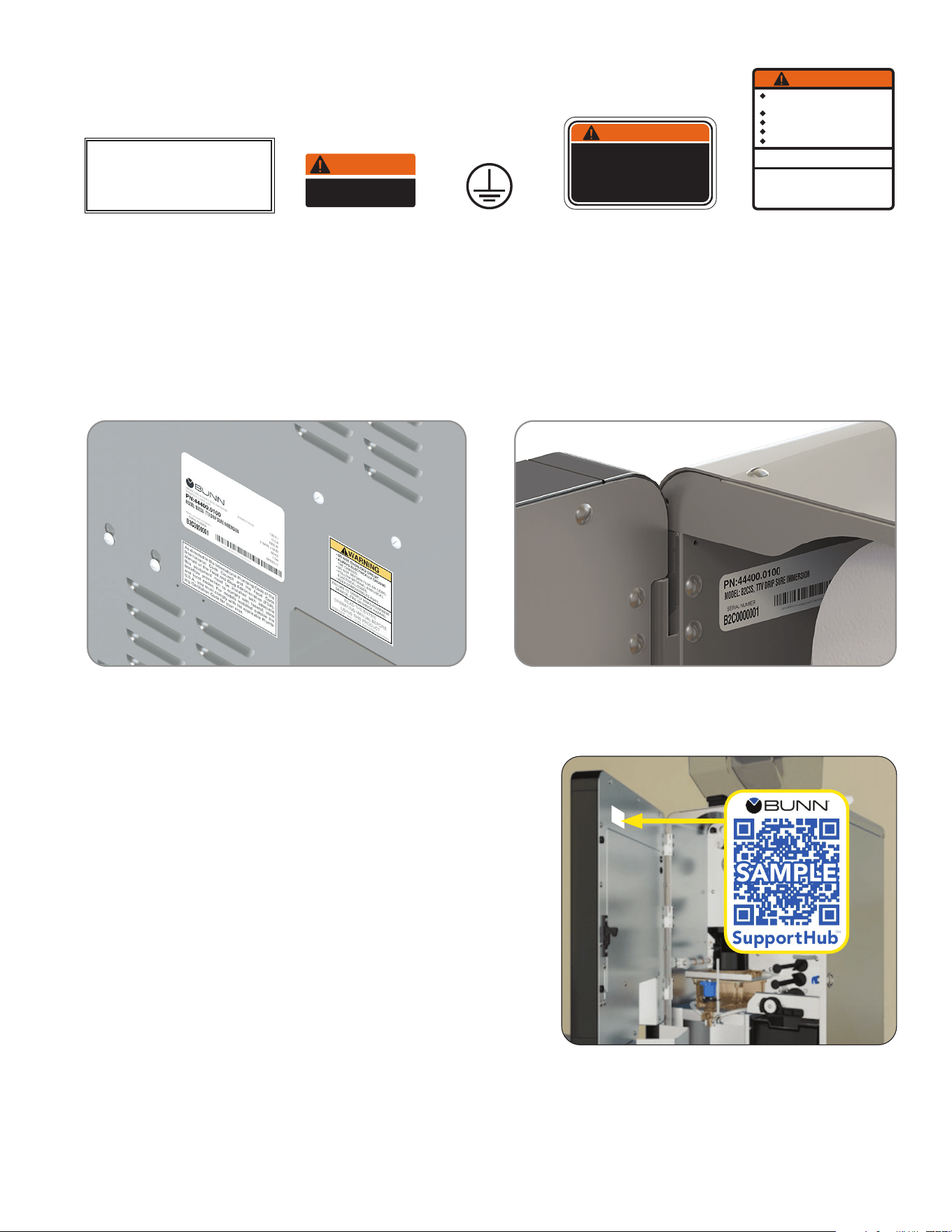
The serial number is located on the data plate at the rear of the machine and inside front door on left side.
The complete serial number will need to be documented on all work orders and warranty tags.
LOCATIONS OF SERIAL NUMBER
BUNN SupportHub
®
BUNN SupportHub provides easy access to comprehensive
information and resources tied to the specific serial number
for this product. Open the door and scan the QR code with
any smart device for access to manuals, product information,
training videos, service support and other related information.
SUPPORT
6
SITE REQUIREMENTS
As directed in the International Plumbing Code of the Inter-
national Code Council and the Food Code Manual of the
Food and Drug Administration (FDA), this equipment must
be installed with adequate backflow prevention to comply
with federal, state and local codes. For models installed out-
side the U.S.A., you must comply with the applicable Plumb-
ing /Sanitation Code for your area.
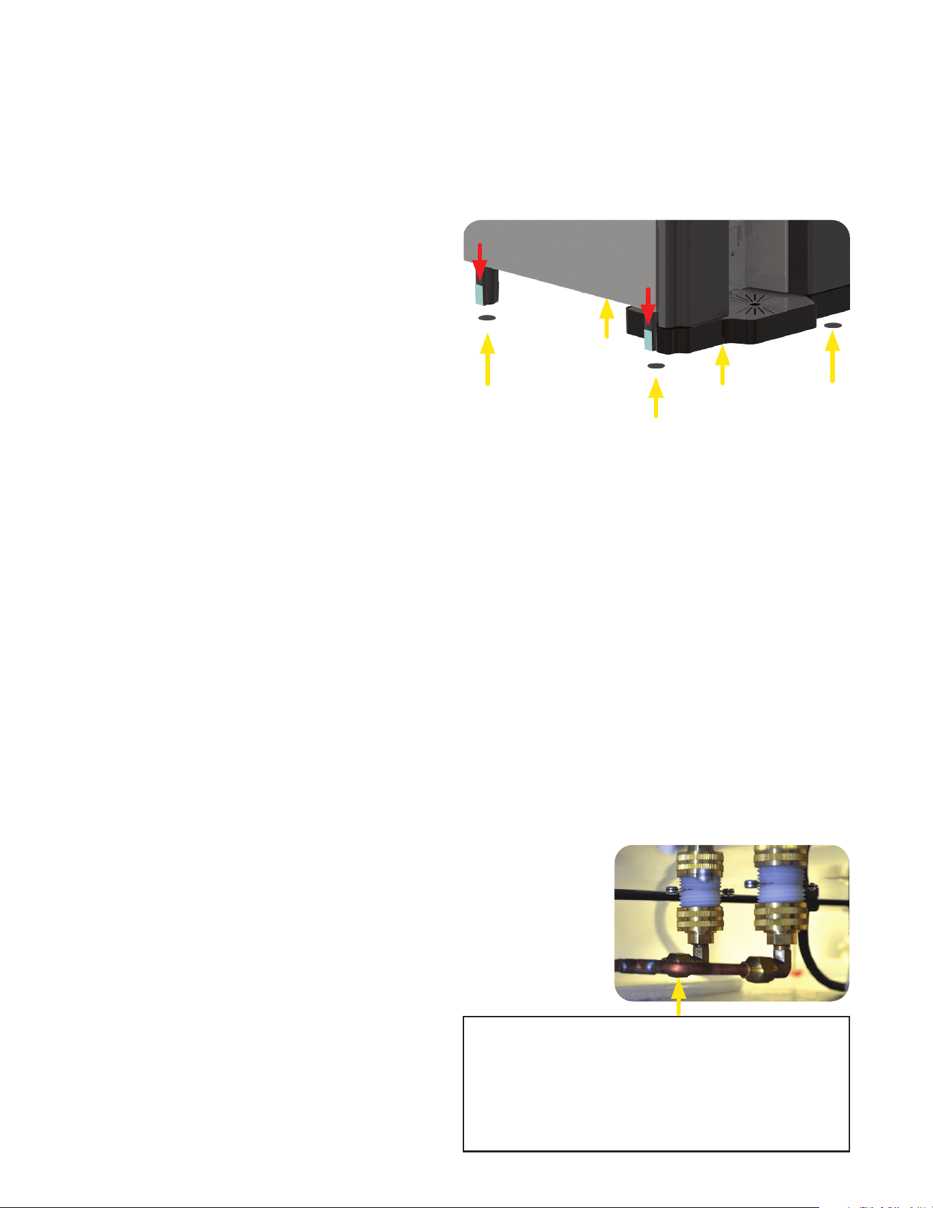
PLUMBING HOOK-UP: The plumbing connections
are located on the bottom of the unit, using a manifold
(included) that connect to a water line using a
1/4 inch connection.
NOTE: Water pipe connections and fixtures
directly connected to a potable water supply
shall be sized,
installed, and
maintained in
accordance with
federal, state,
and local codes.
Counter Requirements
1. Counter able to support at least 200 pounds (90kg).
2. Counter area large enough for machine.
3. Minimum clearance of 2˝ around machine.
4. Machine must be level within 2˚ for proper operation.
Plumbing
1. These brewers must be connected to a cold
water system with operating pressure between
20 and 90 psi (0.138 and 0.620 MPa) from a
1/4 inch or larger supply line. Install a regulator
in the line when pressure is greater than 90 psi
(0.620 MPa) to reduce it to 50 psi (0.345 MPa).
NOTE: Requires a minimum of 1 gallon per
minute flow rate.
2. Shut off valve should be present between water
supply and machine.
3. Flush the water line and securely attach it to the
inlet fitting at the rear of the brewer.
4. Turn on the water supply.
5. Check for leaks.
Location of the Serial Number
The serial number is located on both the data plate
at the rear of the machine, and a decal inside by the
RH powder hopper. The complete serial number will
need to be documented on all work orders and
warranty tags.
WARNINGS
The brewer must be disconnected from the power source until specified in Initial Setup. Refer to Data Plate
on the Brewer, and local/national electrical codes to determine circuit requirements.
Counter Top Installation
1. Remove tape from all five legs.
2. From the parts box, install a 03996.0000 foot
pad on each leg.
NOTE: For through counter grounds disposal,
the rubber feet must be installed on the bottom
of the legs to ensure alignment between the
ground chute and counter top opening.
Tape (remove)
Install Foot Pads
Tape (remove)
INITIAL SETUP
• Unplug the machine or turn off the main switch before servicing the interior components of the machine.
• Never operate the machine without water.
• Never touch brew module, spouts, and hot water dispense pipes. They are HOT and could cause burns.
• The machine must be operated with clean water. Make sure to use water filters and/or softeners as needed.
NOTE: Bunn-O-Matic recommends ¼" copper
tubing for installations of less than 25 feet and
3⁄8 inch for more than 25 feet from the ½ inch water
supply line. A tight coil of copper tubing in the water
line will facilitate moving the brewer to clean the
counter top. Bunn-O-Matic does not recommend
the use of a saddle valve to install the brewer. The
size and shape of the hole made in the supply line
by this type of device may restrict water flow.
Water Treatment
1. No Chlorine, no chloramines
2. Water Hardness 6 to 10 grains (total hardness)
3. Water Filtration System
7
Electrical Hook-Up
CAUTION
Improper electrical installation will damage
electronic components.
1. An electrician must provide electrical service
as specified.
2. Using a voltmeter, check the voltage and
color coding of each conductor at the
electrical source.
3. Connect the dispenser to the power source
(plug it in).
4. Locate the switch at the rear of the machine and
flip the power switch to the "ON" position
NOTE: The boot-up sequence may take
60-90 seconds, and the machine will cycle in
preparation for operation. The door must be
closed, or the door interlock engaged at
power up.
5. If plumbing has been hooked up, the dispenser
will auto-fill and heat.
6. After the boot-up sequence is complete, open
the door and remove the cardboard shipping
pad from the top of the brew box.
INITIAL SETUP
POWER SWITCH
LOCATION
(back of machine)
Cardboard Shipping Pad before boot-up
Cardboard Shipping Pad after boot-up
(remove after boot-up)
- FOR INDOOR USE ONLY -
Configuration
120V Configuration:
This electrical service consists of 2 current carrying conductors
(L1 and Neutral) and a separate conductor for chassis ground.
120-208/240V Configuration:
This electrical service consists of 3 current carrying conductors
(L1, L2 and Neutral) and a separate conductor for chassis ground.
continued >
X
W
Y
G
120-208/240V MODELS
120V Models
PN 26367.0000
1/4 inch Cleaning Brush
PN 42933.0001
Sure Immersion Cleaning Tablets
PN 50766.0001
Paper Roll
PN 53465.0000
Micro Fiber Cleaning Cloth
PN 52444.0020
Door and Bean Hopper Key
PN 53493.0000
Small Cleaning Brush
ACCESSORIES
8
INITIAL SETUP
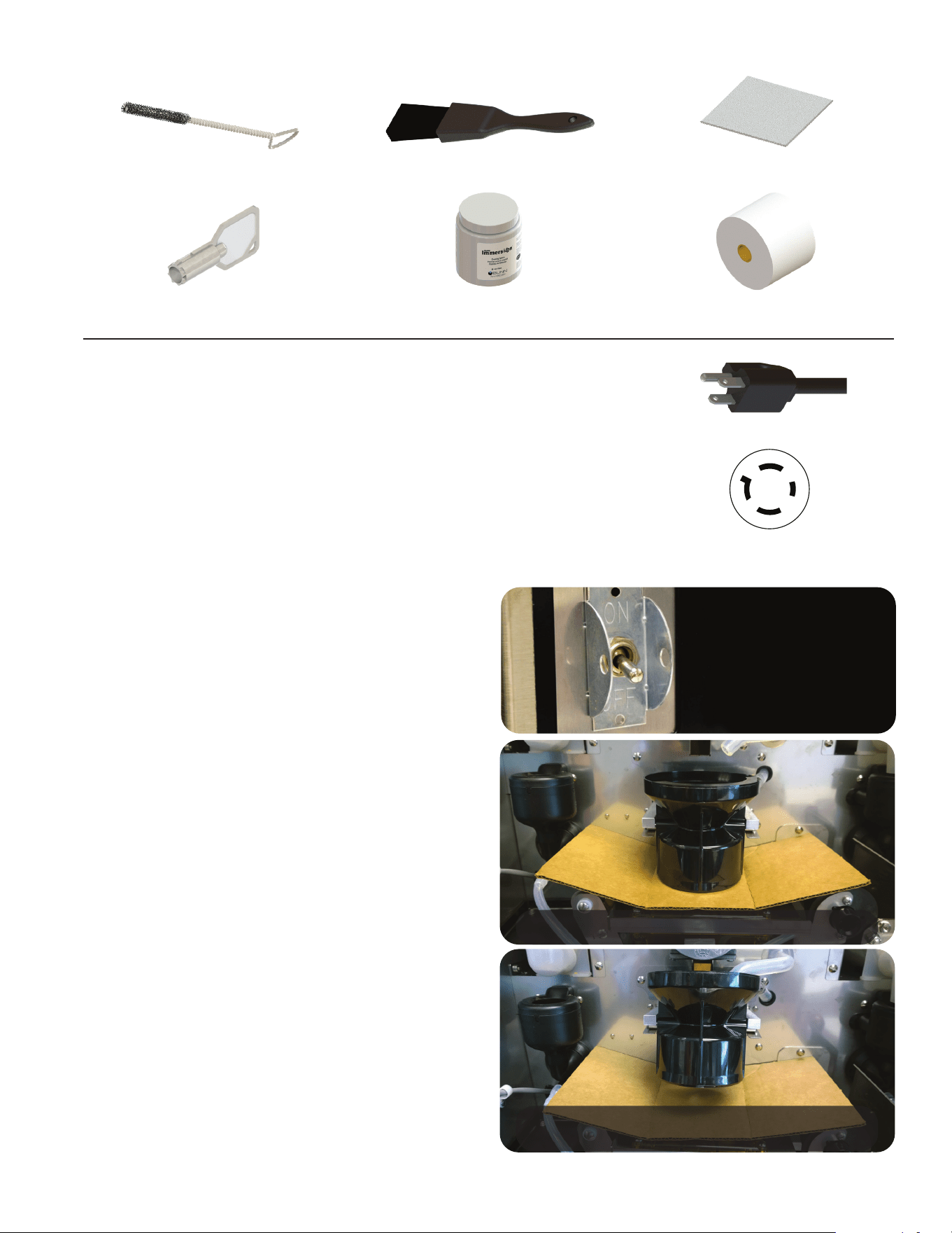
Bean Hopper Setup
1. Remove the bean hopper from the packaging;
taped to the lid is the lid lock key - DO NOT
LOSE THIS KEY. When not being used, keep
the lid key in a secure place. The hopper is
divided into three compartments with a lockable
lid.
NOTE: DO NOT FILL hoppers prior to installing
because the weight of a filled hopper makes
installing it difficult.
2. Prior to installing the bean hopper, visually
verify that there are no obstructions or debris
blocking the bean hopper location and bean
detection sensors.
3. Close the bean hopper chutes by sliding the
hopper lock mechanism (Red Ball) to the right
as shown. This will allow the bean hopper to
properly locate once installed.
NOTE: This must be done to remove the hopper
and also prevent any beans from spilling from
the hopper.
Hopper Lock Ball
Bean Hopper with Lid Key
Bean Fill Level Detectors
continued >
1
2
3
9
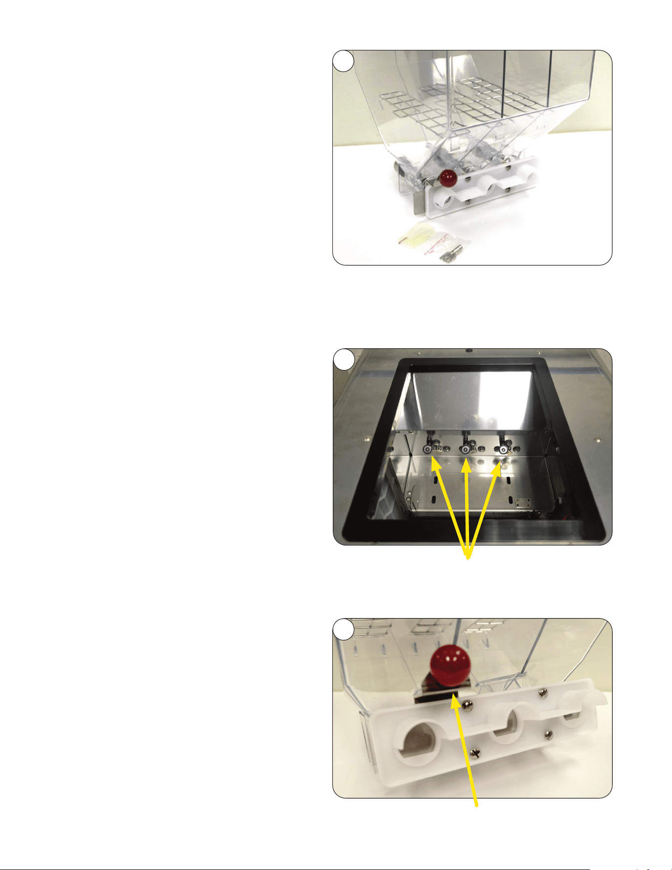
Bean Hopper Setup (continued)
4. Install the Bean Hopper into the machine as
shown. Some minor movement may be required
to settle the hopper into its proper seating.
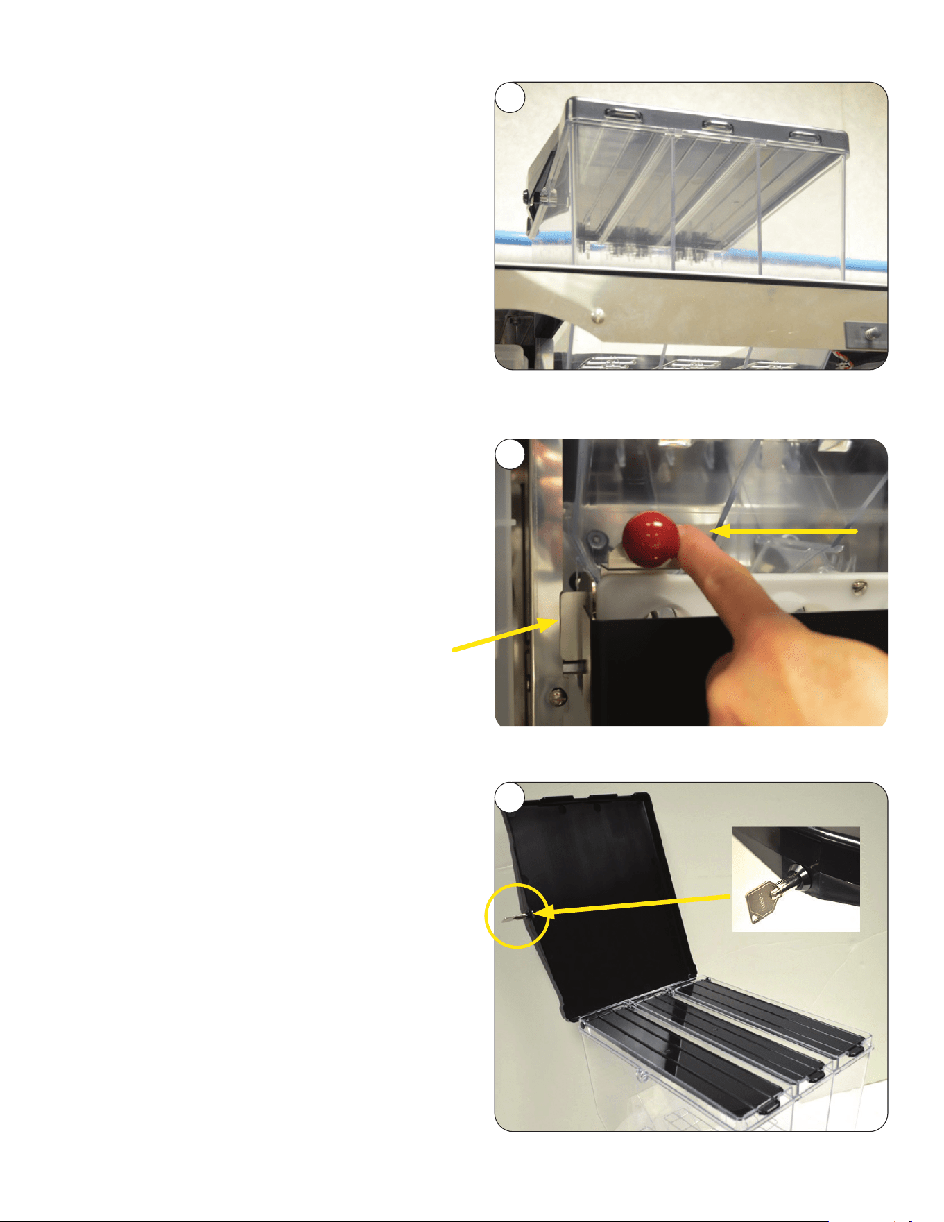
6. Insert Hopper Lid Key into key hole located on
the left side of the Bean Hopper Lid as shown.
Once the lid is unlocked, lift the lid, and you
have access to each of the three bean compart-
ments.
NOTE: At this point, go ahead and fill each of the
hoppers with the beans that make up your
unique recipes. Close the lids, and then close
and lock the main hopper lid.
5. Lock the Bean Hopper into place by pushing the
hopper lock mechanism (Red Ball) to the left as
shown. Doing this will slide a metal tang into a
slot, thus preventing the bean hopper from
being removed as well as allowing the beans to
flow from the hoppers when the bean augers are
engaged. Failure to do so may result in improper
machine performance or damage to the hopper.
Metal Tang
INITIAL SETUP
continued >
4
5
6
10
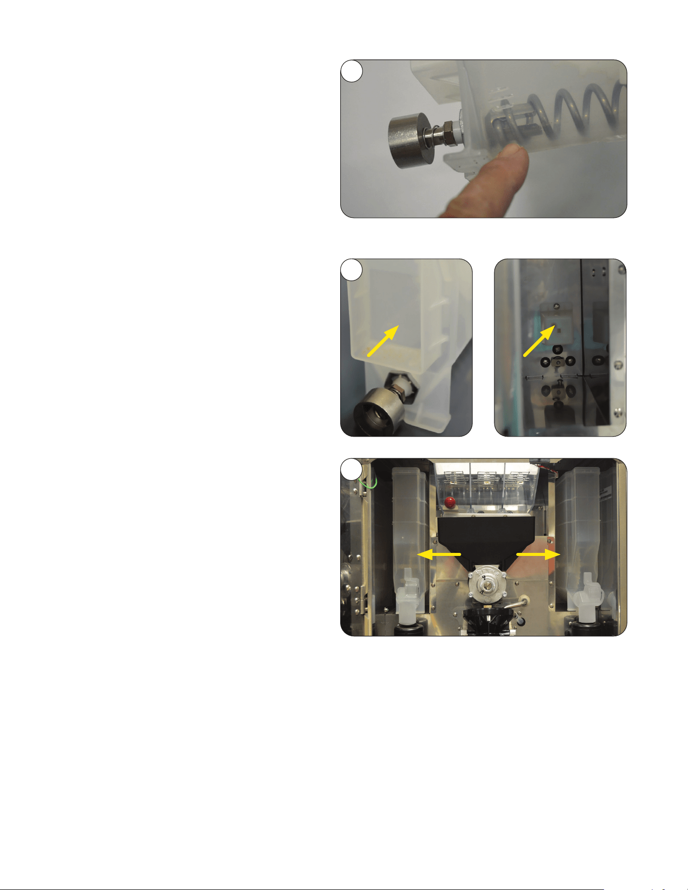
Powder Hopper Setup
1. Remove the powder hoppers from the
packaging. Before filling each with the
appropriate product, verify that the auger
spring is in it's correct position. If the auger
spring is not engaged, rotate the auger
driveshaft clockwise till the auger spring is
fully seated as shown.
2. Before installing the powder hoppers, take note,
that at the rear of each hopper is a cavity that
corresponds with a locating block in each of the
powder hopper locations. When a hopper is
placed in position, the locating block fits into
the cavity, thus ensuring proper powder hopper
placement. Also, the front of the hopper needs
to be placed behind the retaining tab directly
behind the whipper mixing bowl.
3. Fill the hoppers, then install one on either side of
the machine as shown.
INITIAL SETUP
continued >
1
2
3
11
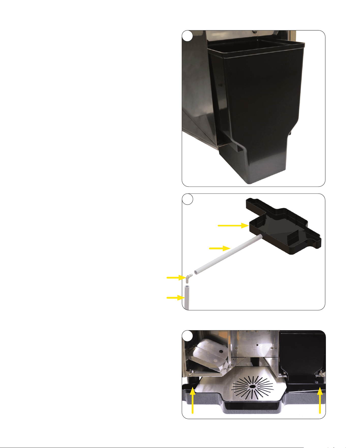
3. Position the drip tray as shown. When properly
placed, the drip tray fits up against the front legs
of the machine.
Waste Bin / Drip Tray
1. Remove the waste bin from the packaging, and
install as shown. A magnet is located on the
back of the bin.
NOTE: An optional through counter waste bin is
available for unattended sites.
2. Unpack the drip tray/cover. Remove the tape
securing the cover.
If setting up to have drip tray drain through
a counter, a hose will need to be attached.
Using a 3/8 inch drill bit, make a hole in the
extension on the back to the drip tray. Then
attach a 5/8 inch (inside diameter) hose with
a minimum rating of 200˚F. The hose needs
to flow downhill to work properly.
Suggested set-up if draining drip
tray through a counter.
3/8" hole drilled in extension, 5/8" hose
attached, and a 90˚ elbow connector to
ensure liquid flows downhill.
90˚ Elbow
Hose
Hose
Drip Tray
INITIAL SETUP
continued >
1
2
3
12
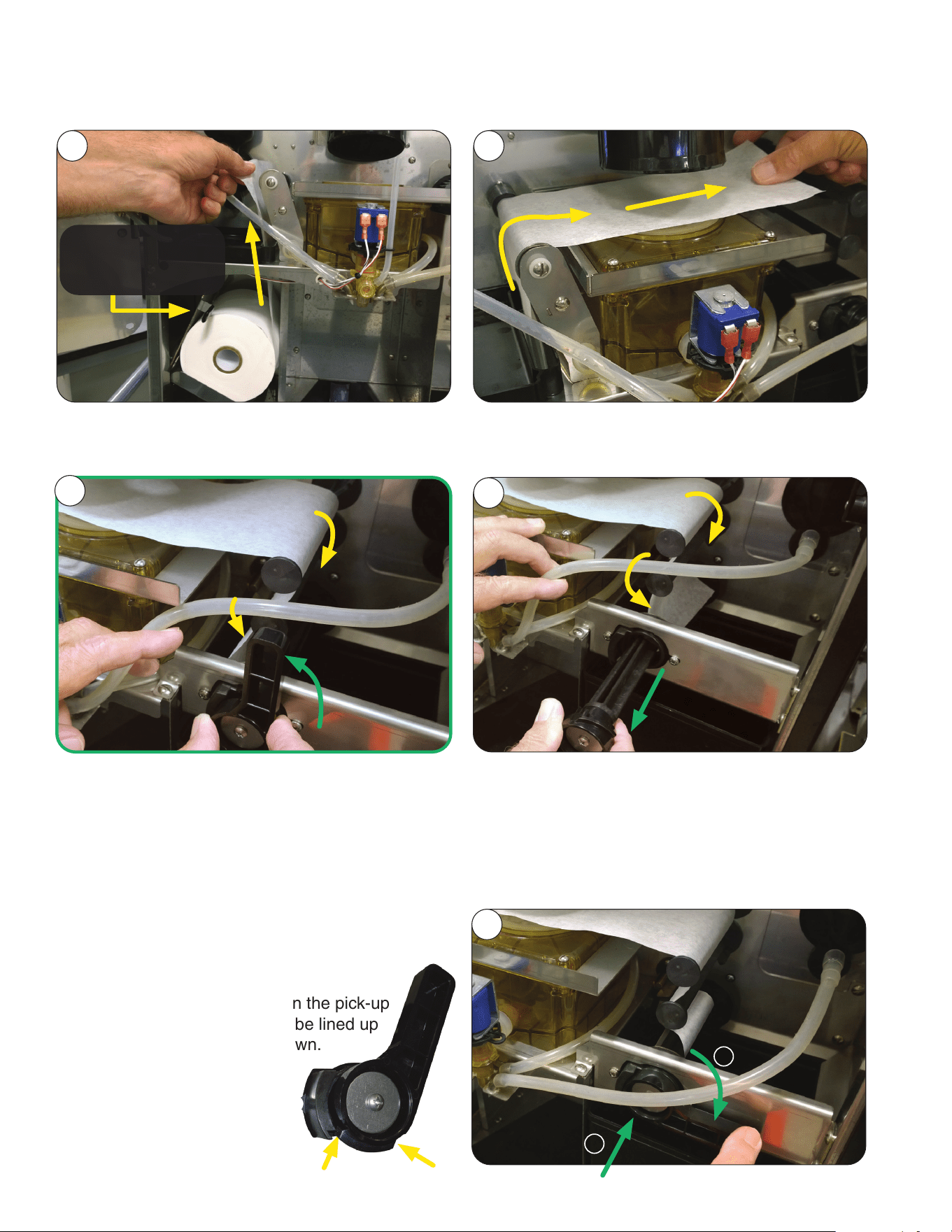
Filter Paper Installation
Install filter paper roll and then route the filter paper through the tractor drive as shown.
1. Pull the end of the paper roll up, and over
left roller.
2. Pull end of paper between the Brew Funnel and
Brew Box
3. Continue paper over the top spindle, then on the
left side of the middle spindle. Feed the paper
in front of the pick-up (bottom) spindle with the
handle. Flip the handle a quarter turn to the left.
4. Pull the handle out as shown, and place the
paper in the slot that goes the length of the
pick-up spindle.
1
2
THE PAPER WEIGHT
MUST BE ON TOP OF
THE ROLL
5. With the paper inserted into the slot of the
bottom spindle, 1) push the spindle in, 2) then
down a quarter turn to the right.
NOTE: There are notches on the pick-up
spindle handle that need to be lined up
before pulling the handle down.
These notches hold the
handle in place when the
automatic paper advance
is in use.
INITIAL SETUP
continued >
1 2
4
5
3
13
BUNNLINK ACTIVATION
continued >
These instructions are for connecting BUNNlink
from a compatible machine through WiFi using an
Ethernet connection.
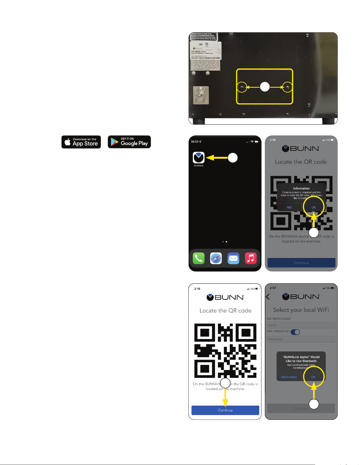
Ethernet WI-FI Board Activation
1. If you are connecting to an Ethernet cable,
remove the 2 screws and then the back
panel they hold to locate the Ethernet cable port.
If you are using WiFi only, proceed to next step.
2. Download the latest version of the BUNNlink
Mobile App to your smart phone through either
the Apple
®
App store for IOS or Google Play
®
store for Android.
NOTE: It will appear with the BUNN logo icon.
4. The app will ask you to enable the camera to
scan the QR code.
Select OK.
3. Open App when complete.
6. The app will ask permission to use Bluetooth.
Select OK.
5. This screen will display once accessed.
Press the CONTINUE button.
3
4
5
6
1
14
BUNNLINK ACTIVATION
continued >
continued from previous page
* * * *
The location’s Wi-Fi network name and
password is required before BUNNlink
activation.
If you experience any issues with activation; contact
BUNN Tech Services at (800) 286-6070 or
email: bunnlink@bunn.com.
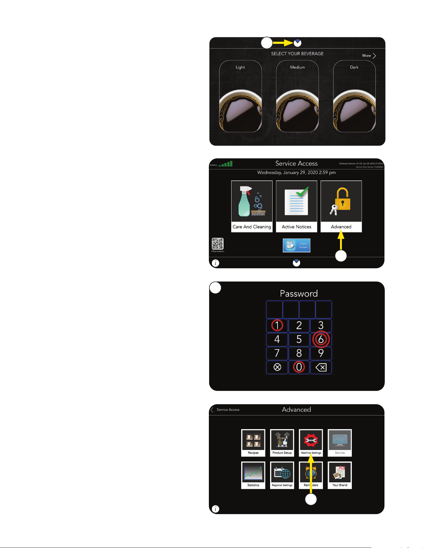
2. Select Advanced button
Steps to find out:
1. Press the BUNN Logo to open Service Access
screen.
1
2
3
4. Select Machine Settings.
3. Select 6601 for Password.
4
15
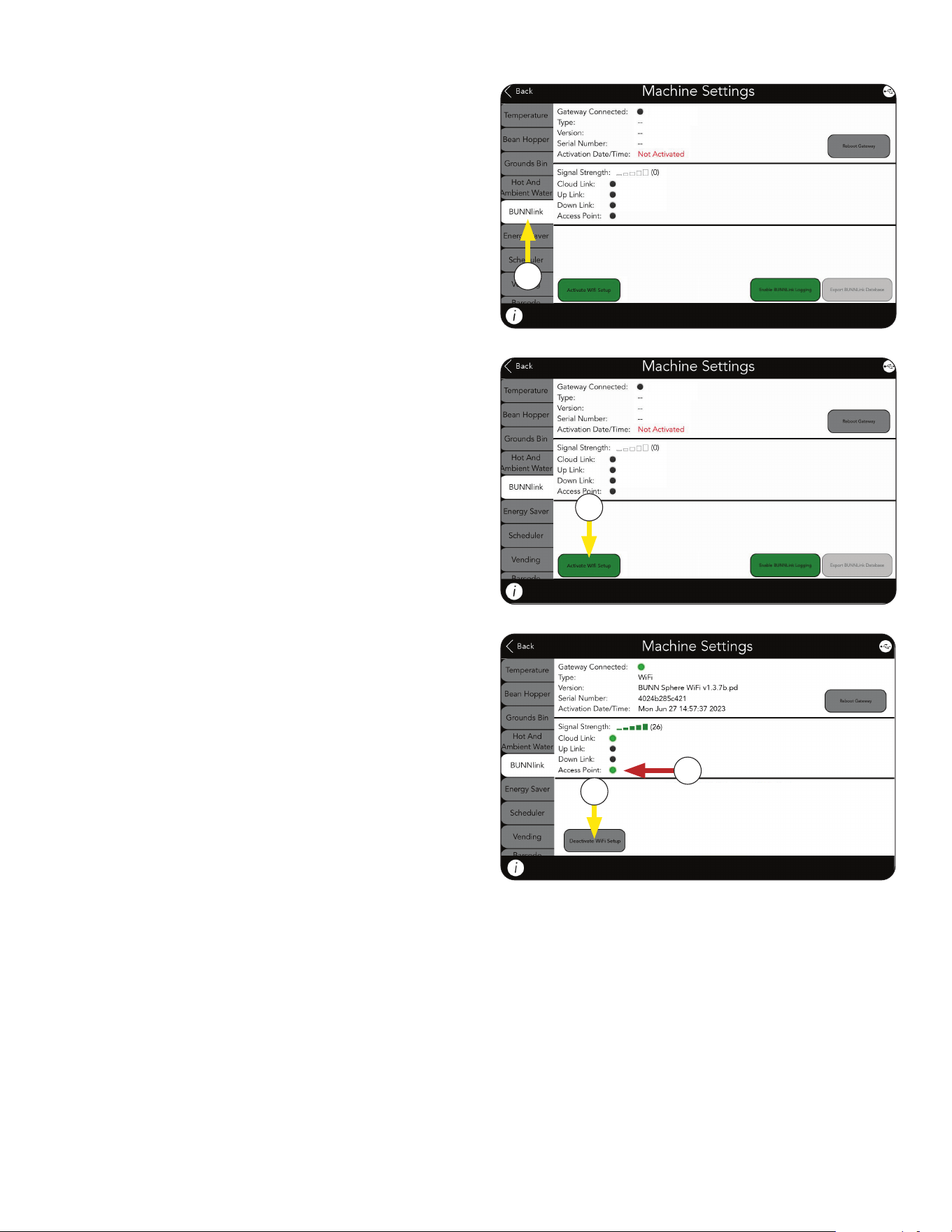
BUNNLINK ACTIVATION
5
5. Select BUNNlink Tab.
6. If not active, click on the Activate WiFi
Setup button.
6
continued from previous page
7
7. The button should change to grey and say
Deactivate WIFI Setup.
8. The Access Point dot should turn green.
NOTE: If Access Point is dark, power cycle the
machine for 5 minutes and start over.
8
continued >
16
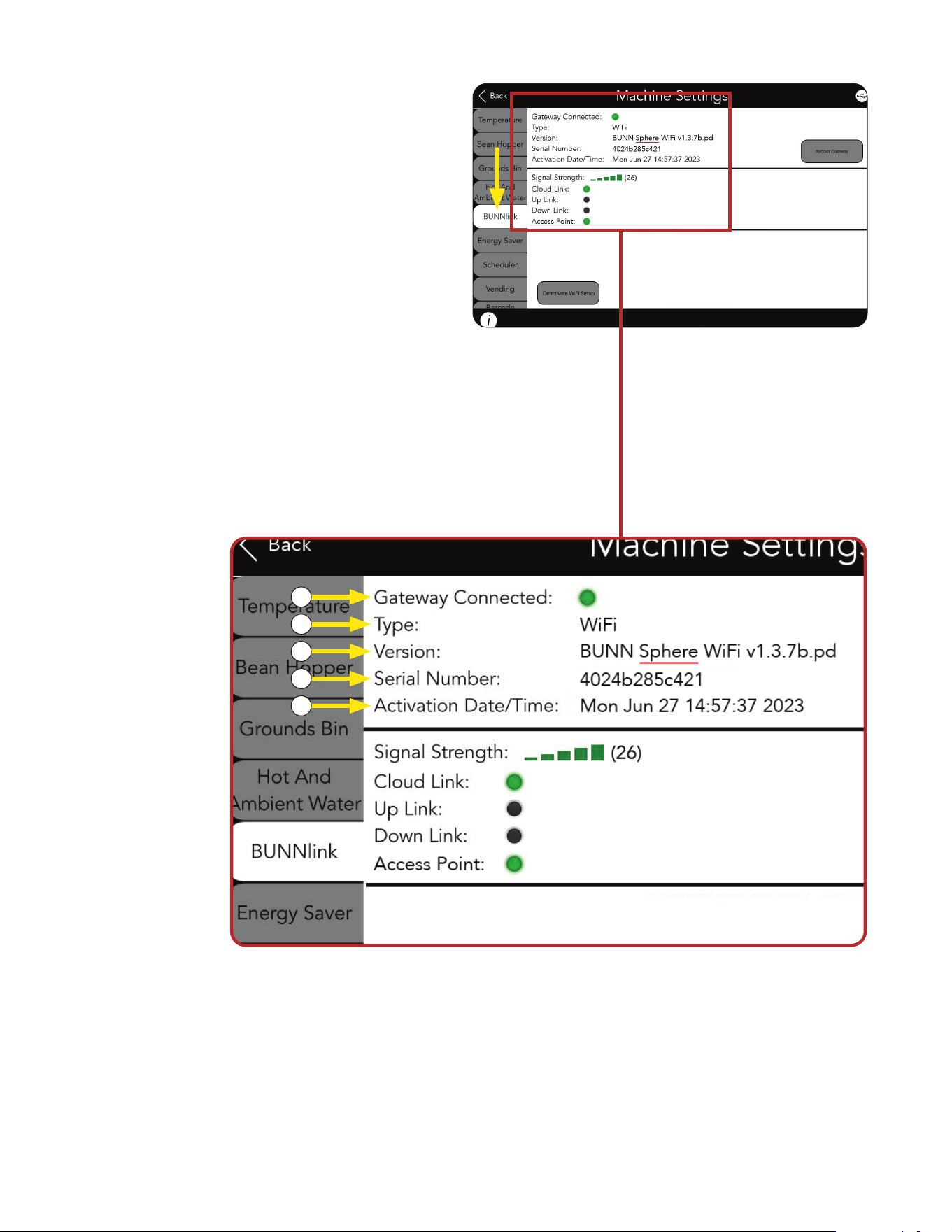
BUNNLINK ACTIVATION
continued >
continued from previous page
a. Gateway Connected should be green to
indicate the machine and BUNNlink
gateway see each other.
b. Type of board shown as WiFi.
c. Sphere WiFi type should appear with/its
software version.
d. The Serial Number that appears on this
screen is the Mac Address for a Bunnlink
WiFi board.
BUNNLINK TAB INFORMATION
WHEN ACTIVE
b
a
c
d
NOTE: If whitelisting is needed, this is the
12-digit Mac Address that should be added
to the list.
e. Activation Date/Time when BUNNlink was
first enabled on the machine’s interface.
e
Fig. 1
17
continued >
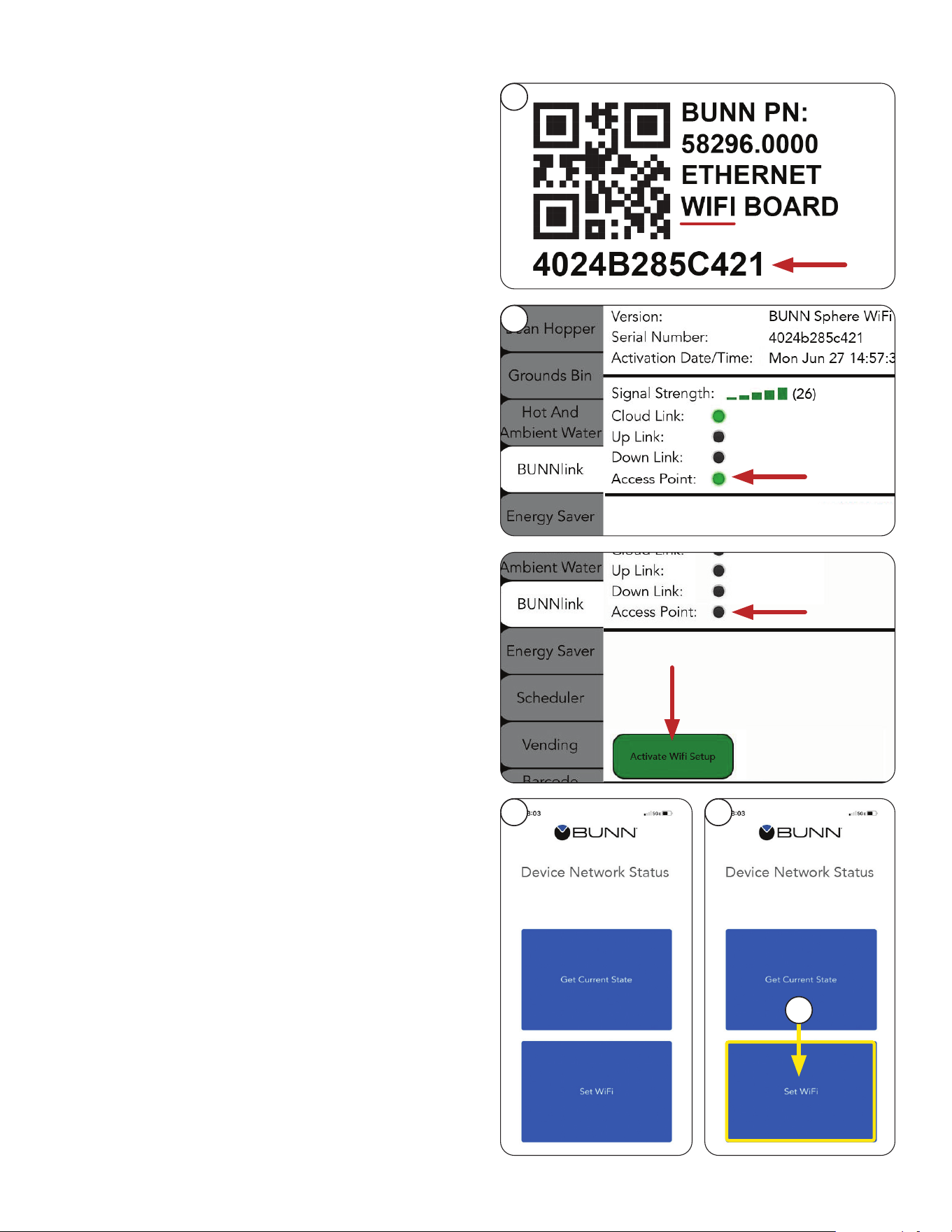
BUNNLINK ACTIVATION
9. Locate the QR Code decal either behind the
display or behind the door.
The decal should say it is for an Ethernet WiFi
Board and include a Serial Number with 12
alpha numeric characters underneath the
QR code image.
10. From the machine, go to the BUNNlink tab.
The Access Point should be green.
Proceed to step 12.
NOTE: The Serial Number that appears on the
decal should match the one on the screen ex-
ample in Fig. 1 (d).
NOTE: New kits will have a decal behind the
board, on the anti-static packaging, plus a spare
decal to stick on the machine when replacing or
installing a board.
11. If the Access Point is not green, click on the
Activate WiFi button.
When Access Point is green, proceed to
step 12.
12. Scan the QR code using the BUNNlink Mobile App.
NOTE: It may take a couple of attempts.
Sometimes pulling back away from the image
while scanning works better than trying to get
the camera too close.
If you can’t scan the QR code, contact
[email protected] or 217-331-8428.
Leave a message if necessary. Your call will
be returned.
13. Connect to the WIFI Board. After a successful QR
Code scan, two buttons will appear on the mobile
app – Get Current State and Set WiFi on the
Device Network Status screen.
14. On the mobile app, click on Set WiFi.
continued from previous page
9
10
12 13
14
18
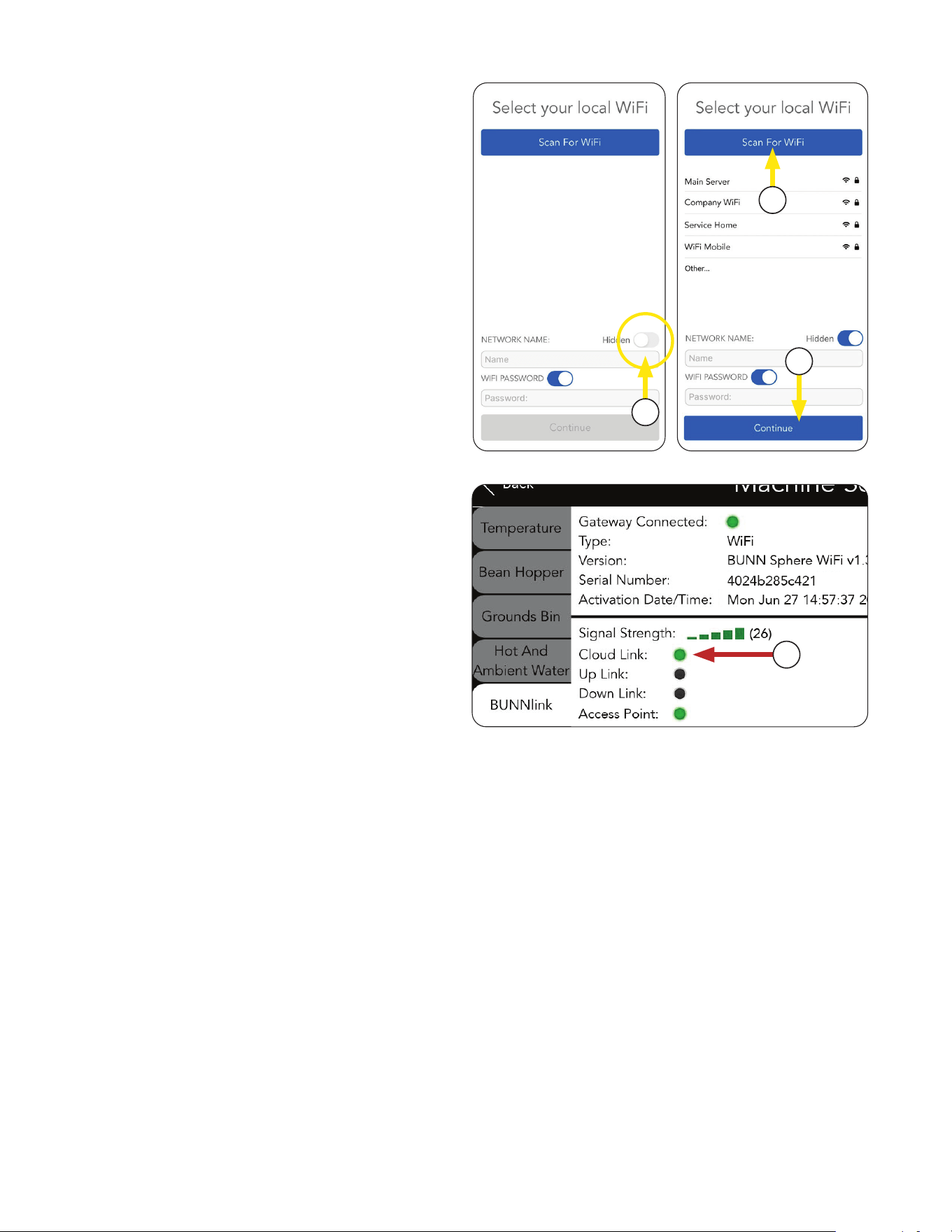
BUNNLINK ACTIVATION
17. Click Continue.
NOTE: If it fails, see Troubleshooting section.
18. If successful, Cloud Link will turn green and
become steady, signal strength will show
green bars.
YOUR CONNECTION IS NOW COMPLETE.
15. If you are connecting to a hidden network,
enable the Hidden toggle located on the app
before Scanning for WiFi.
If successful, a list of available networks
will appear.
16. If you have the location’s network name and
password, you may enter it manually, or select
the name from the list of available networks and
enter the password.
continued from previous page
16
18
17
15
19
OPERATING INTERFACE
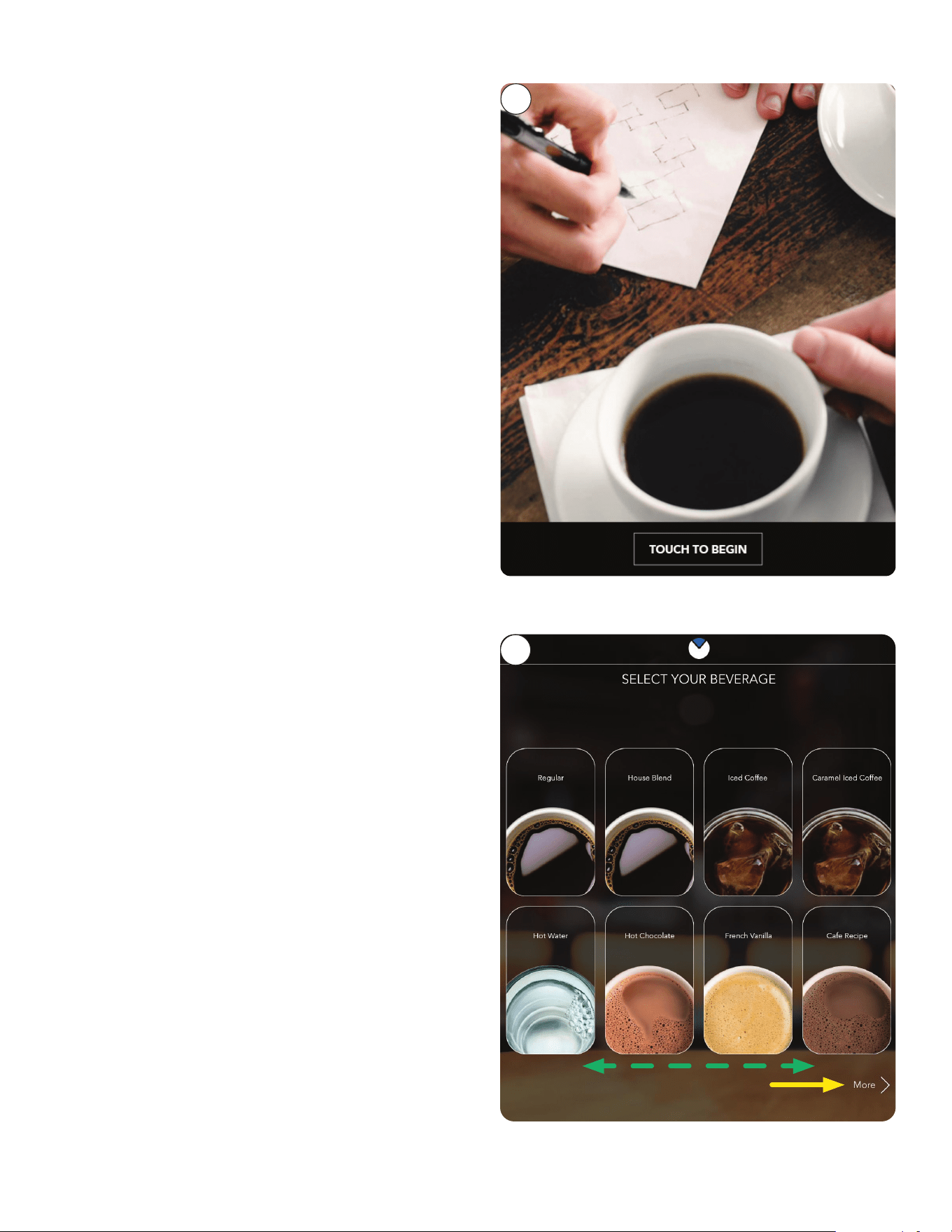
1. The first screen to appear is the "Screen Saver".
Touch the screen to begin.
2. From the main menu (Selection) screen, the
user is offered beverage choices. The user
selects one to proceed.
NOTE: If you have more than eight BEVERAGES
set up, and you don’t see all of them on the
screen, either swipe side-to-side by pressing the
images, or press the MORE Arrow on the
bottom right corner to scroll through.
continued >
3. Once a selection has been made, the user then
presses the "OK" button to proceed or the "X"
button to cancel the selection.
1
2
20
OPERATING INTERFACE
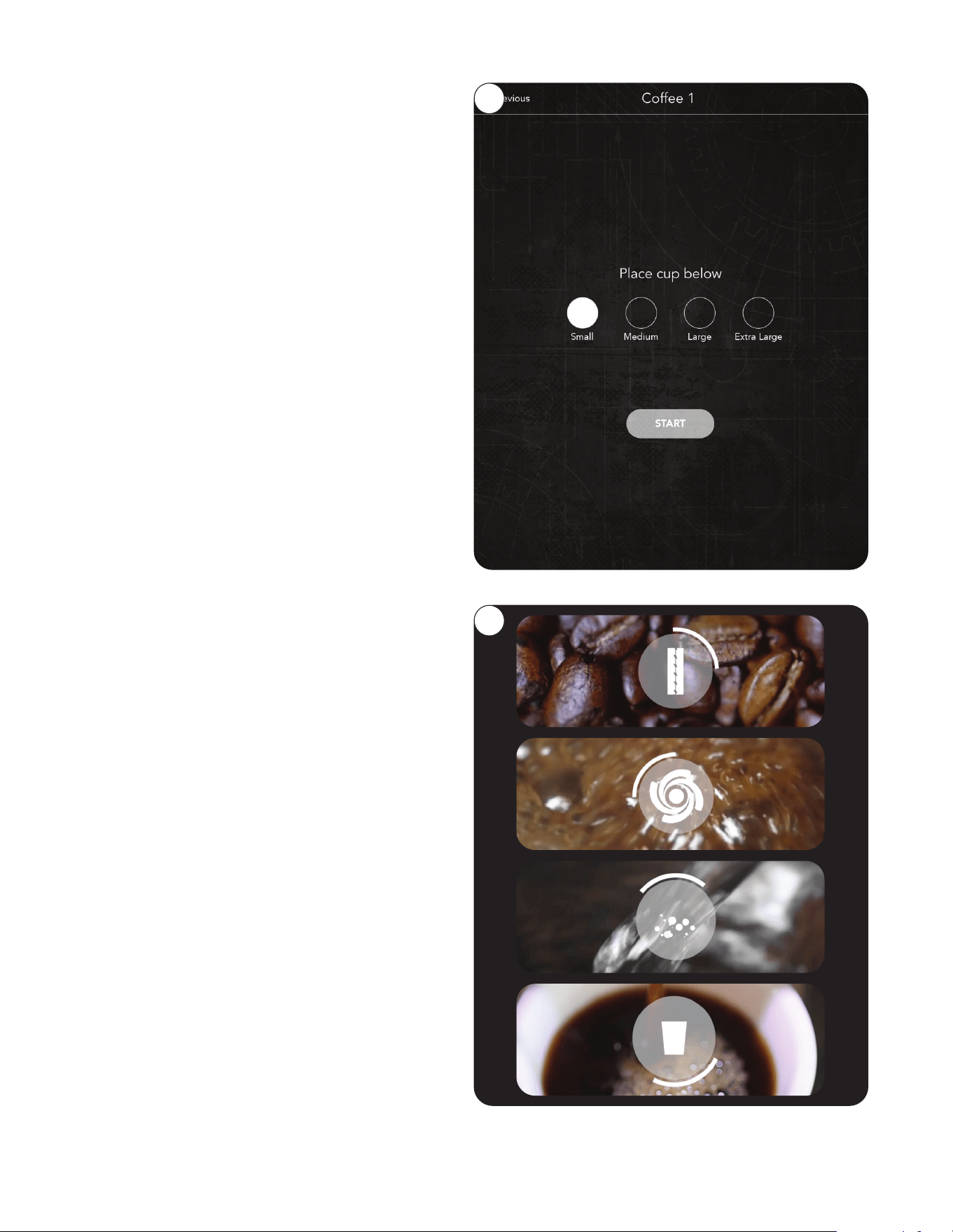
4. From the "COFFEE" screen, the user is
prompted to make a size selection. The user
is offered up to 4 cup sizes, plus optional
carafe. "SMALL", "MEDIUM", "LARGE" and
"EXTRA LARGE". Once a selection has been
made, successive screens walk the user
through the chosen beverage preparation,
step-by-step with static and video imagery.
NOTE: In the upper left corner of the screen is
a back arrow button that will allow the user to
return to the previous screen.
5. The chosen beverage preparation is shown in
step-by-step visuals... Grinding... Immersion...
Brewing... and Dispensing.
4
5
21
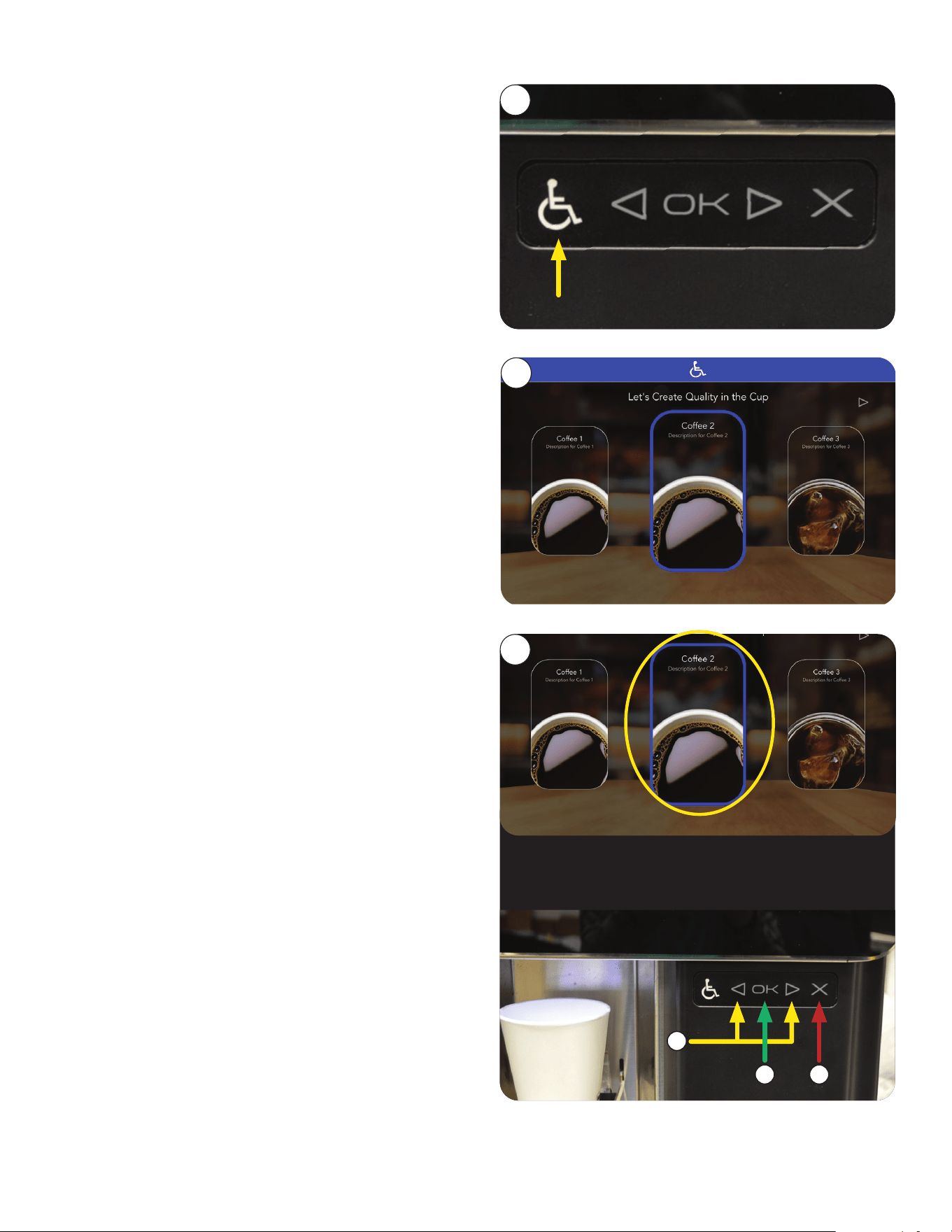
3. Navigate around the screens using the Left and
Right arrows on the ADA interface.
a. Select a beverage
(using left and right arrows).
b. Press the "OK" button to confirm it.
c. Pressing the "X" cancels the selection.
NOTE: If the beverage selected is an Iced
Beverage, the screen will prompt the user to
fill the cup with ice prior placing the beverage
container (cup) on the tray.
1. To activate the ADA screen interface, the
user must press the accessibility symbol
(wheelchair icon).
2. When activated, the screen will have a blue
banner at the top, and a blue highlight around
the item being selected.
ADA Interface
For individuals needing access, the ADA control
buttons are located just below the door and to the
right of the dispenser.
OPERATING INTERFACE
a
b c
continued >
1
2
3
22
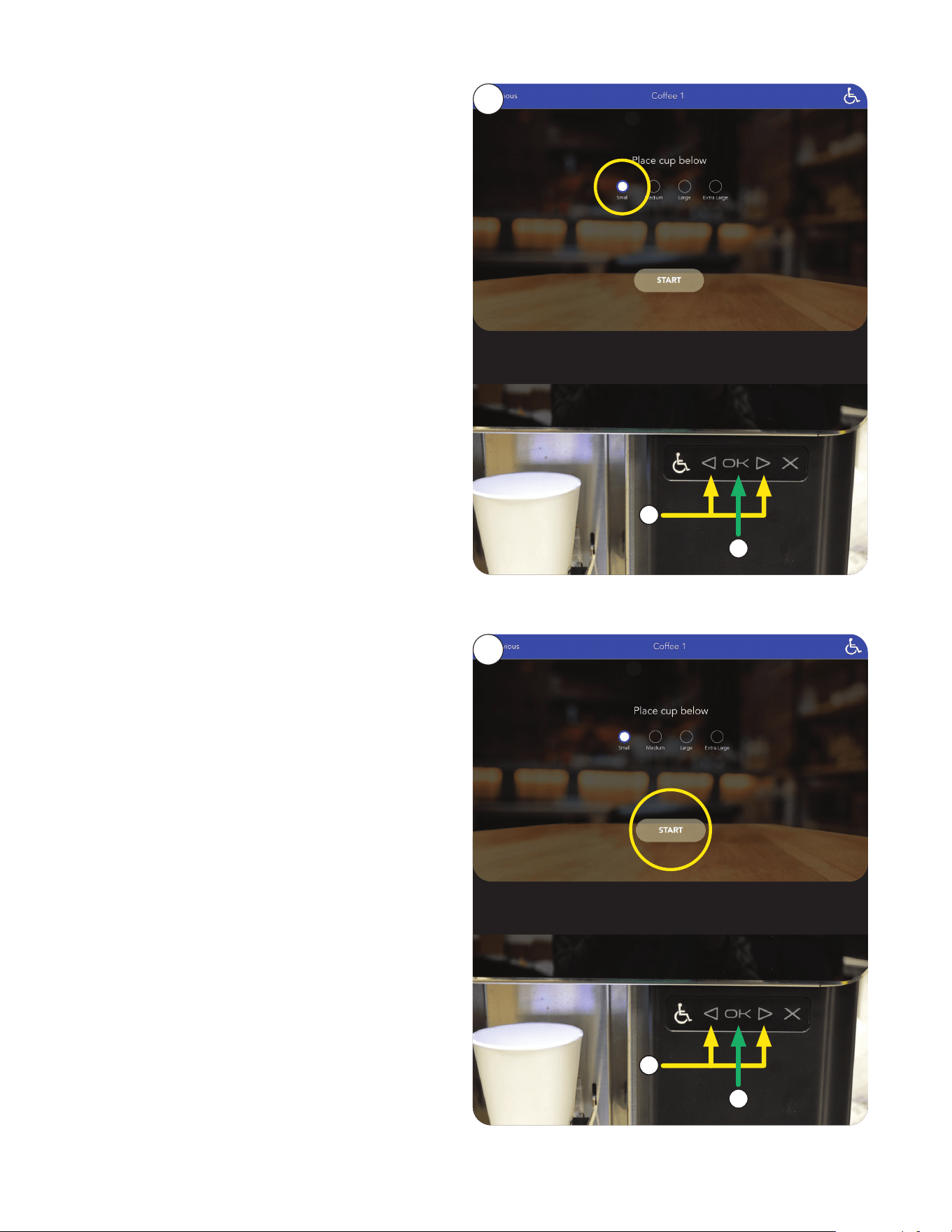
4. Selections available through the ADA interface
on this screen; Previous, Small, Medium, Large,
Extra Large and Start.
a. Next, using the ADA arrows, choose a
BEVERAGE size.
b. Press OK to enter selection.
5. Press the START button.
c. Use Navigate arrows.
b. Press OK.
OPERATING INTERFACE
a
b
c
d
continued >
ADA Interface (continued)
4
5
23
OPERATING INTERFACE
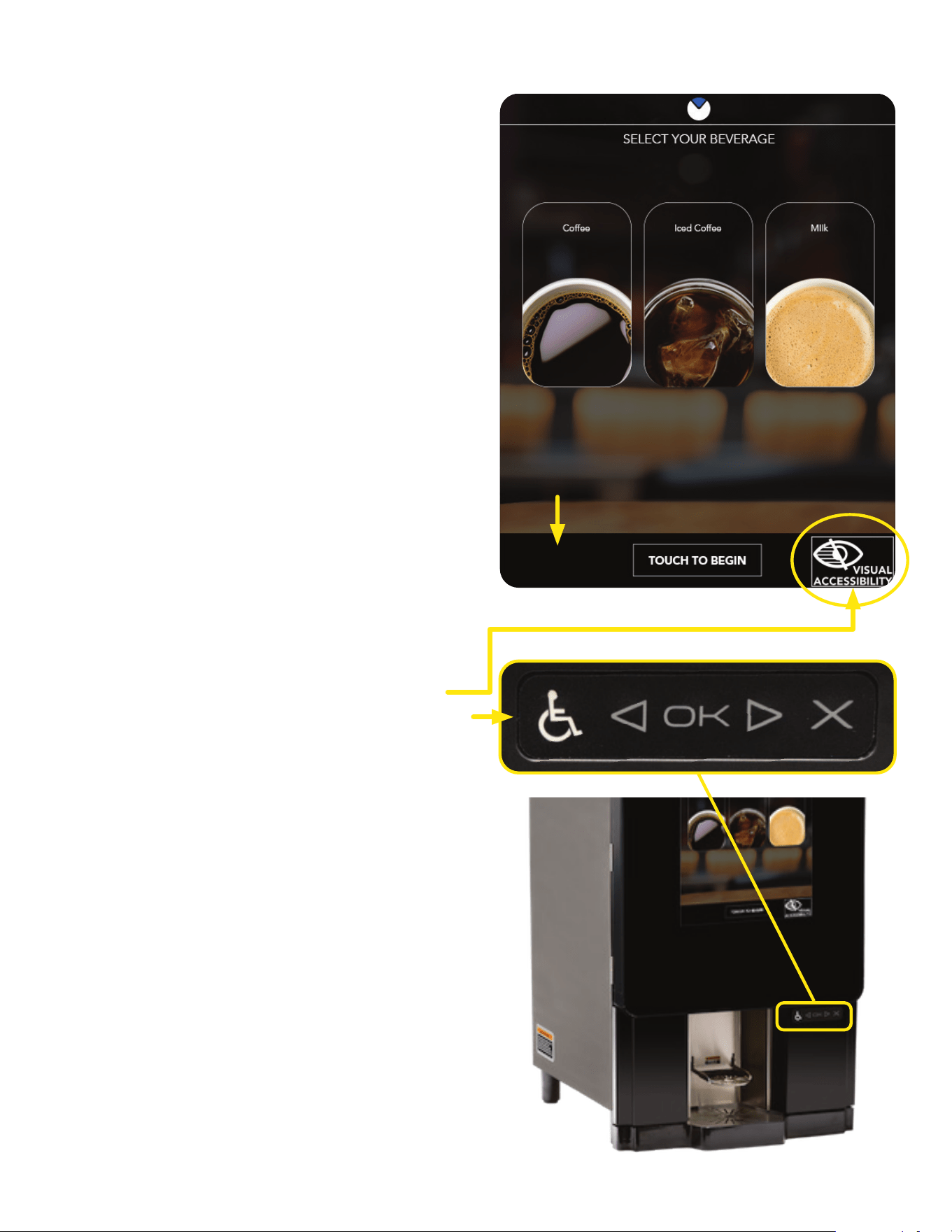
ADA Visually Impaired Interface
NOTE: The ADA CONTROL PANEL is located
just below the door and to the right of the
dispenser.
1. A special mode to provide high contrast and
simplified screens for accessibility for those that
are visually impaired.
A VISUAL ACCESSIBILITY logo is also shown
on the MAIN MENU screen when enabled.
TWO WAYS TO ACTIVATE THE ADA SCREEN
INTERFACE:
a. Press VISUAL ACCESSIBILITY button
on screen.
b. Press any button on the ADA Control Panel.
continued >
If the VISUAL ACCESSIBILITY option is enabled,
a black banner will appear at the bottom of the
SCREEN SAVER screen with a TOUCH TO
BEGIN button.
(Optional Features Available)
24
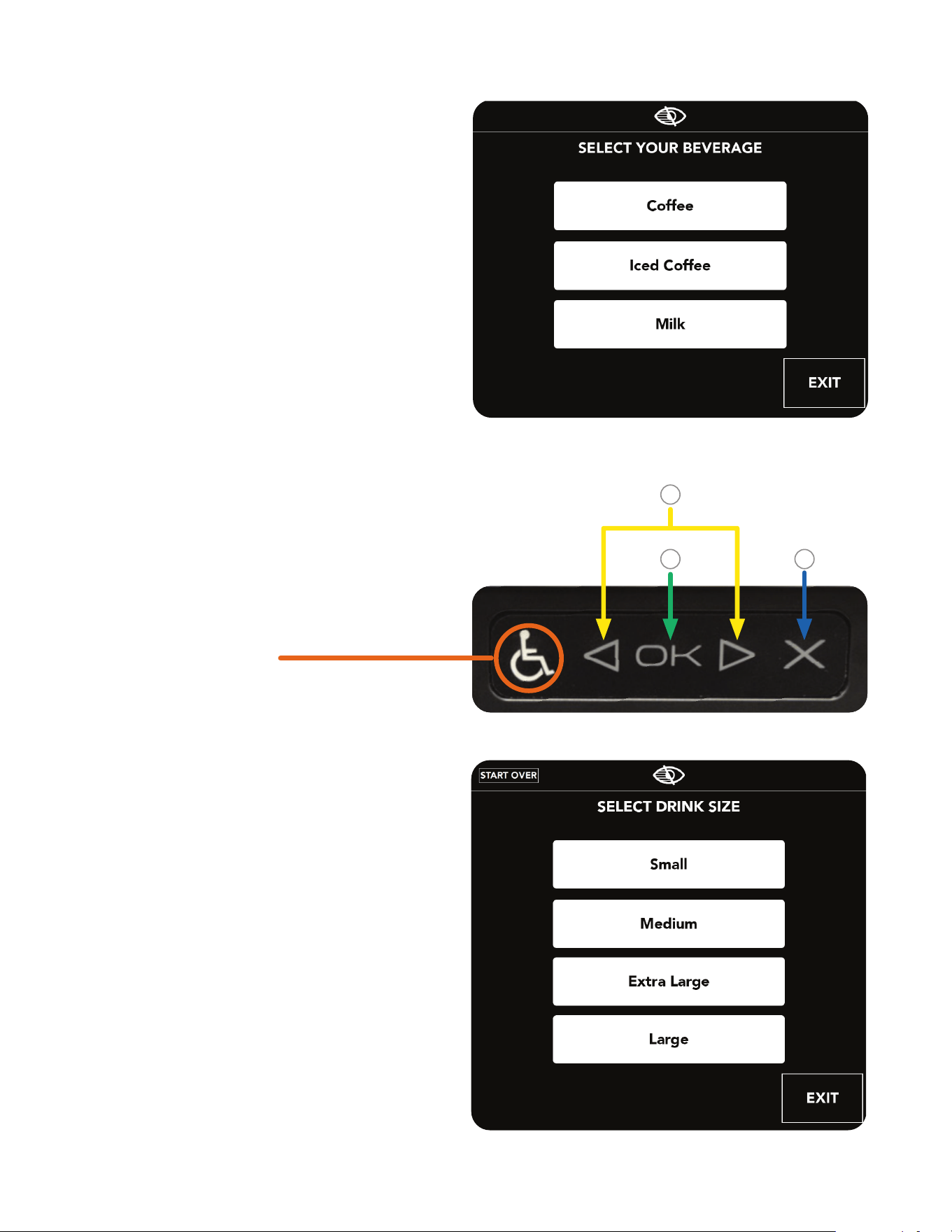
NAVIGATION BUTTONS
OPERATING INTERFACE
ADA Visually Impaired Interface (continued)
NOTE: If the beverage selected is an Iced
Beverage, the screen will prompt the user to
fill the cup with ice prior placing the beverage
container (cup) on the tray.
NOTE: Pressing the "Activation" button at any
time will exit ADA mode.
b
c
3. Select Beverage Size, Start Over or Exit.
continued >
2. Navigate around the screens using the Left
and Right arrows on the ADA interface.
a. Select a beverage.
b. Press the OK button to confirm it.
c. Pressing the X button or the Exit button
cancels and exits the selection.
1. When activated, the Main Menu will appear with
beverage choices.
a
25
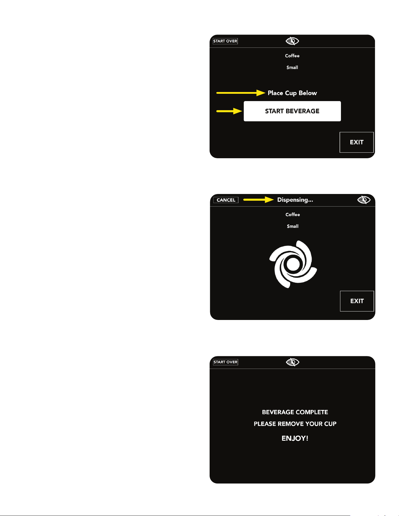
4. A screen will appear asking to
PLACE CUP BELOW.
5. Press the START BEVERAGE button.
6. The beverage process is shown step-by-step...
"Collecting the Beans", "Grinding", "Steeping",
"Filtering", and "Dispensing".
7. Process is done when BEVERAGE
COMPLETE screen is shown.
OPERATING INTERFACE
26
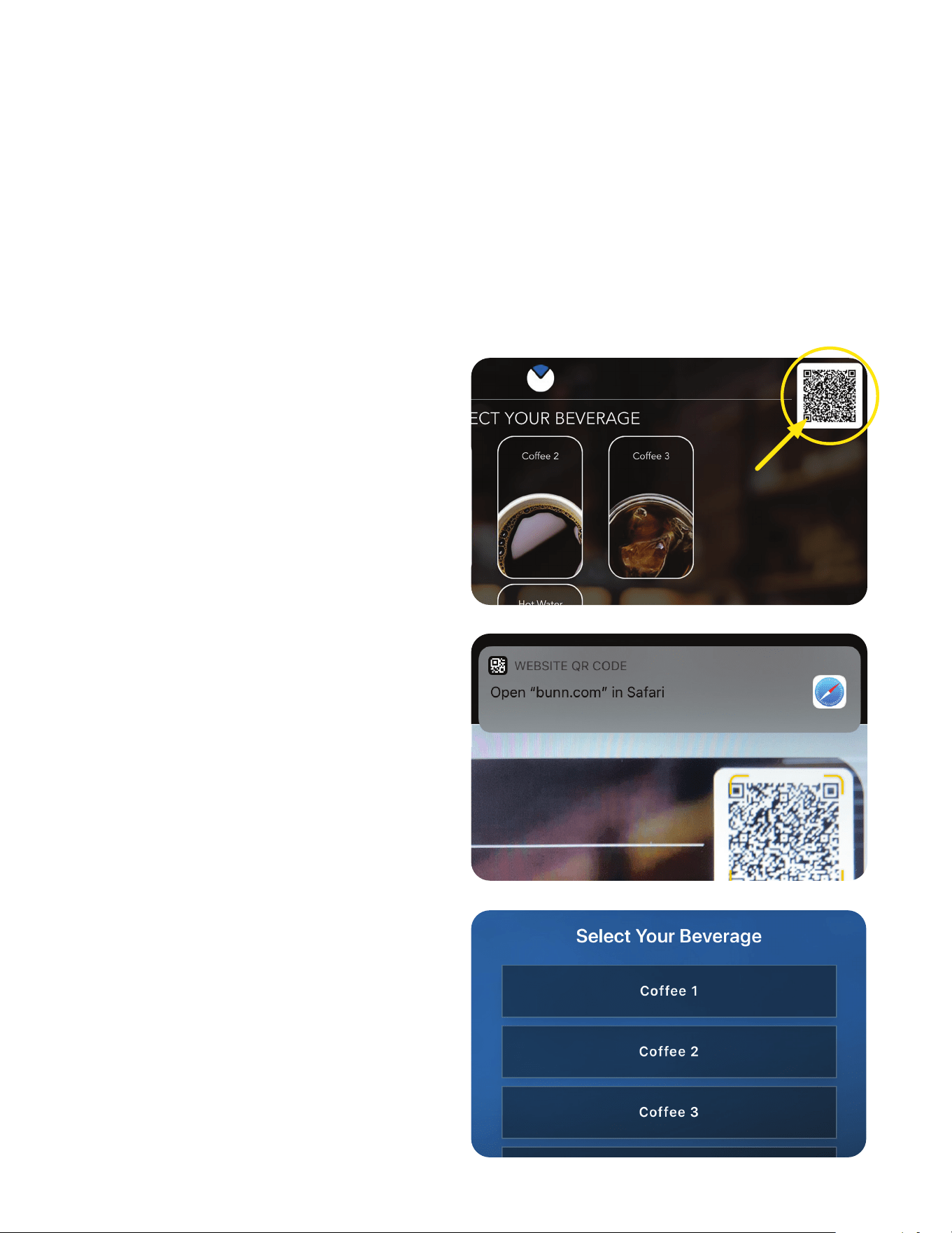
VIRTUALTOUCH OPERATION
BUNN VirtualTOUCH requires a QR code scanner to access the application to dispense a drink. Depending
on what brand tablet or smartphone you carry, it may require you to download a QR code app before using
VirtualTOUCH.
What is needed:
• Installed and registered BUNNlink connectivity on the machine.
• VirtualTOUCH feature enabled on the machine
• Smartphone that can read QR codes (most of the smartphones today are already capable or
you can easily download a free QR code app)
3. Select your favorite beverage shown on the
VirtualTOUCH webpage.
VirtualTOUCH is a beverage dispensing experience that is powered by BUNNlink
®
, our state-of-the-art
cloud based IoT (Internet of Things) solution. Your customers now have the option of selecting and
dispensing a beverage on their favorite bean to cup machine using the most convenient device, their
personal smartphone.
How to use VirtualTOUCH:
1. Use the smartphone to scan the QR Code
visible on the display of the machine.
2. When prompted click on the link to open the
BUNN VirtualTOUCH webpage:
(www.bunn.com/clean-contact-solutions).
It acts just like an APP without the need to install
one from an app store.
NOTE: Your default web browser will vary.
continued >
27
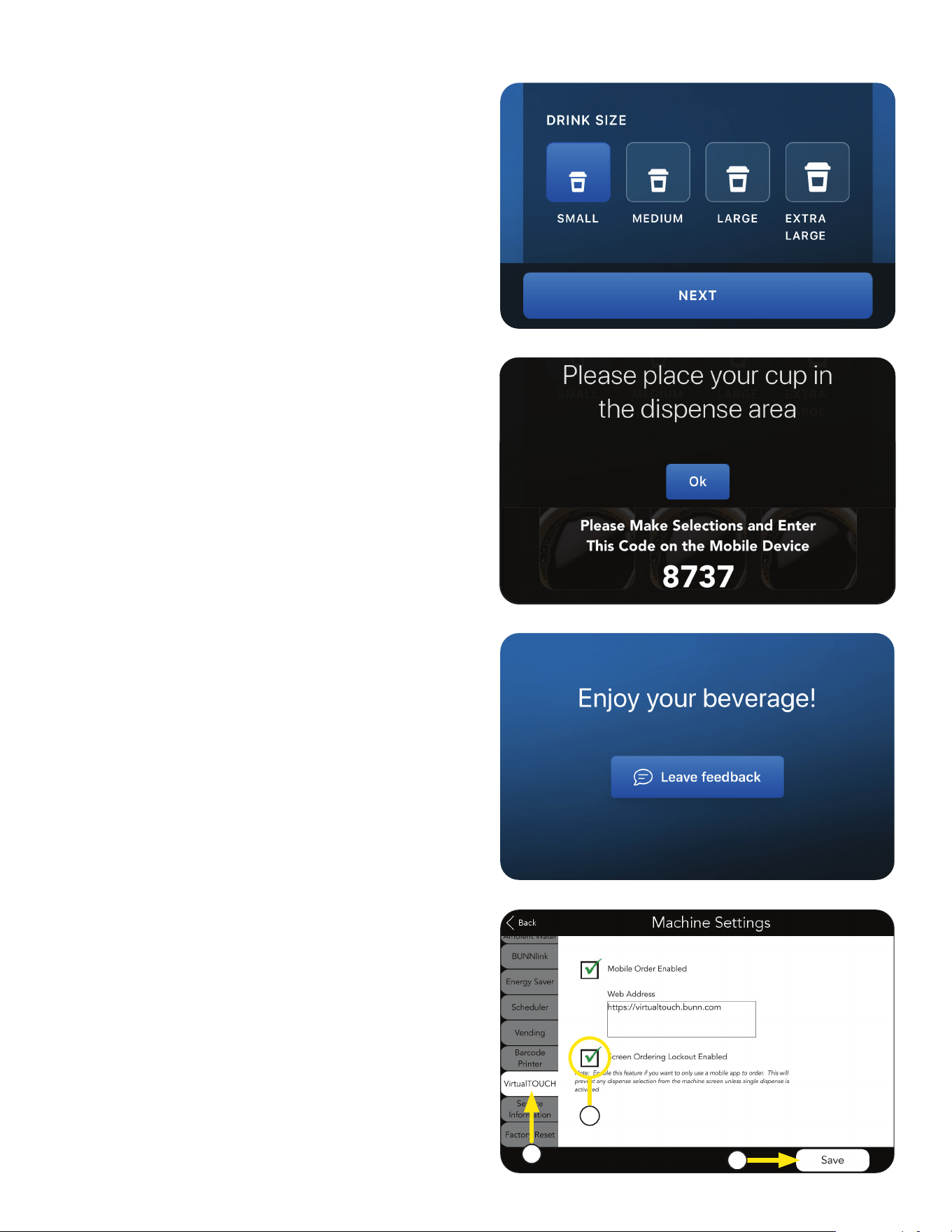
7. Allow time for the beverage to finish dispensing
before removing the cup.
Enjoy!
VIRTUALTOUCH OPERATION
4. Select Size.
Press NEXT.
5. Place your Cup in position. For iced beverage,
place cup with ice in position.
Press OK.
6. Enter the 4-digit code as it is shown on the
display of the machine and press DISPENSE.
NOTE: This is to confirm that you are standing in
front of the machine and ready to take the drink.
Screen Ordering Lockout
Allows you to enable lockout for touchless
dispensing only.
1. In MACHINE SETTINGS select
VirtualTOUCH tab.
2. Select CHECKBOX next to SCREEN
ORDERING LOCKOUT ENABLED to use
this feature.
3. Press SAVE.
1
3
2
continued >
28
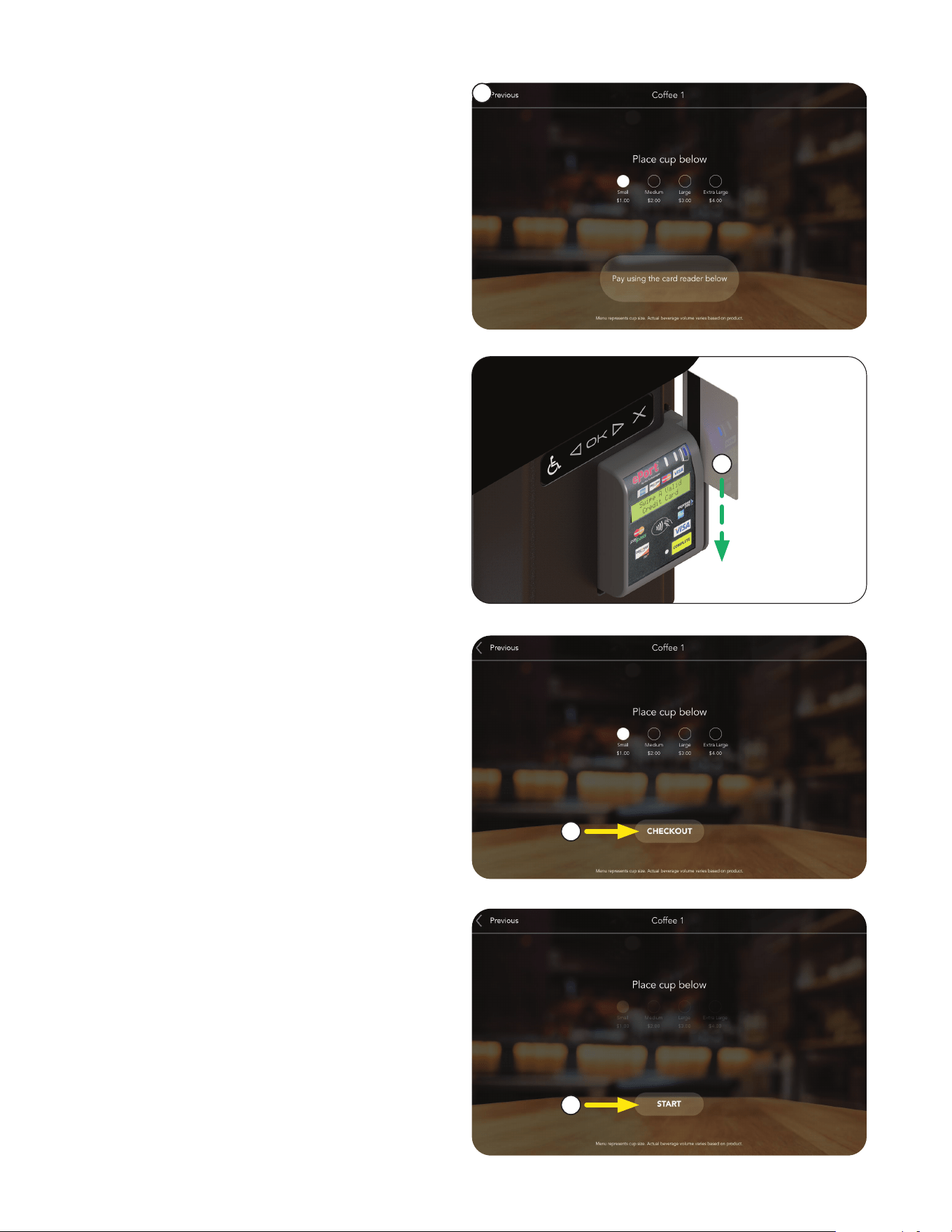
OPTIONAL CASHLESS PAYMENT SYSTEM
1. Place cup under dispense nozzle.
Select CUP SIZE.
2. Swipe credit/debit card to start process.
3. Press the CHECKOUT button to lock in
size selection.
4. Press the START button to dispense.
1
2
3
4
29
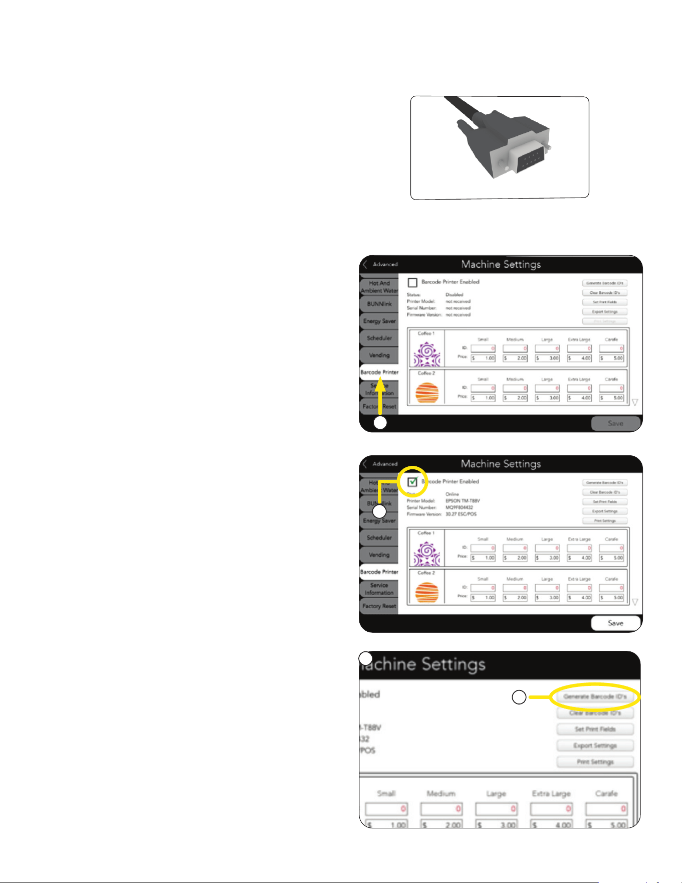
BARCODE PRINTER SETUP
1. If the machine is printer capable, and a printer
has been connected, the machine must be set
up to enable printing.
3. Check the box next to BARCODE
PRINTER ENABLED in the upper left
of the screen.
a. Press the GENERATE BARCODE ID’S
in the upper right corner.
2. Navigate to the MACHINE SETTINGS
screen, and touch the BARCODE
PRINTER tab on the left.
NOTE: Printer hook up to the machine requires a db-9 cable.
4. Barcodes can be entered for each product
two ways - AUTOMATIC and MANUALLY:
AUTOMATICALLY
3
4
2
a
continued >
30
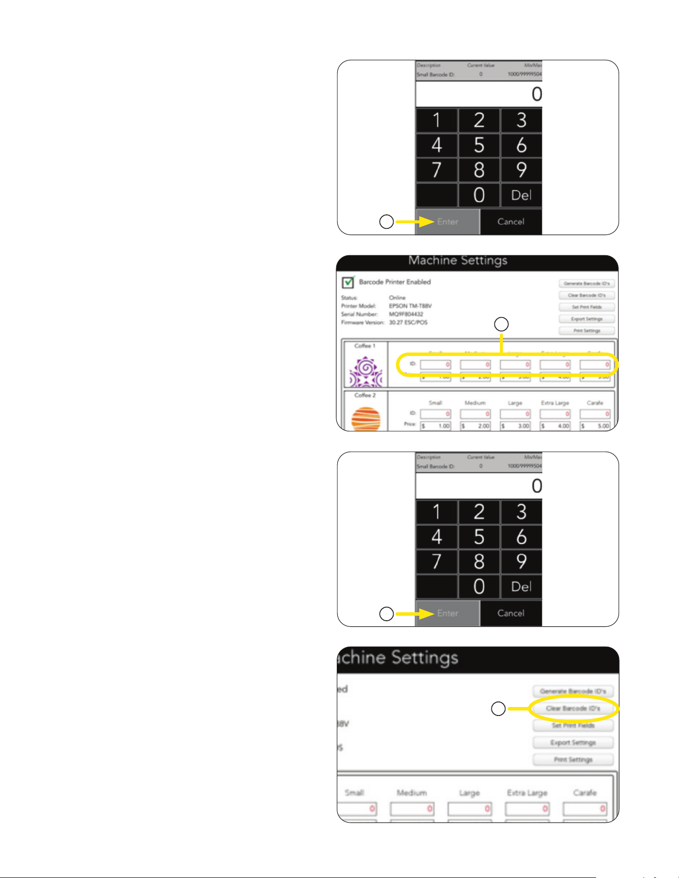
d. The ID fields will be automatically populated
with barcodes, starting with the ID number
you entered.
d. The ID fields will be automatically populated
with barcodes, starting with the ID number
you entered.
BARCODE PRINTER SETUP
a. Barcodes can be manually entered for
each beverage by touching the ID box
for that beverage.
e. Repeat for each beverage and size.
e. Repeat for each beverage and size.
1. Barcode ID's can be cleared by touching the
CLEAR BARCODE ID'S button in the
upper right.
b. Use the keypad to enter the barcode ID
number for the first barcode you require.
Automatically Generate Barcode ID’s
(continued)
c. Hit ENTER
c. Hit ENTER
MANUALLY
Clear Barcode Number
b. The keypad will appear.
c
a
c
1
continued >
31
BARCODE PRINTER SETUP
2. Use the keypad to set the price.
Press ENTER.
Repeat for the remaining sizes and beverages.
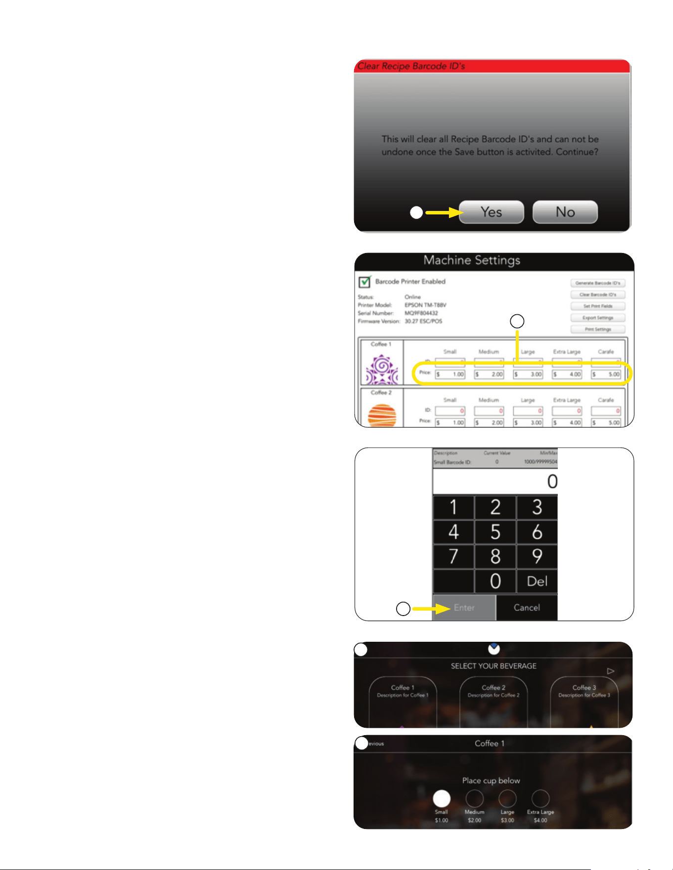
2. Press Yes to clear all barcode ID's, or No to
exit the menu.
Setting Beverage Prices
1. To set the price for a size, press the PRICE box
for the size to be set.
3. The main screen will return.
3
1
2
2
4. Select any beverage.
continued >
5. Verify that the correct price is shown for each
size selection.
5
32
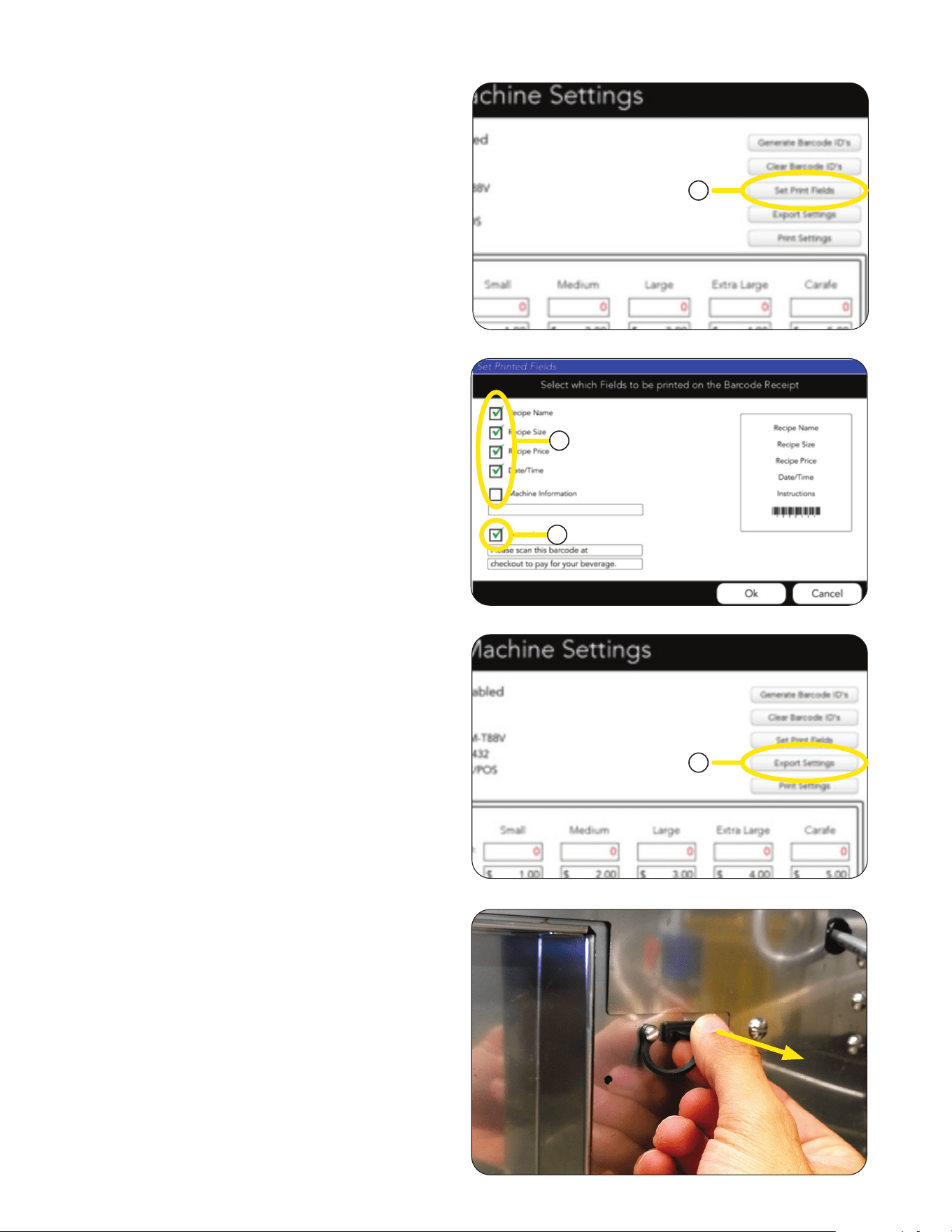
1. The barcode and price settings can be exported
by pressing the EXPORT SETTING button.
BARCODE PRINTER SETUP
2. Check or uncheck boxes to select the
fields which are to be printed on the
barcode receipt.
3. If instructions is checked; touch inside the box
to bring up a keypad to enter the desired
instructions.
4. Press Return key to save, press keyboard icon
on lower right of keyboard to cancel.
Export Settings
1. Fields to be printed can be selected by pressing
the SET PRINT FIELD button in the upper right.
Set Print Fields
2
1
1
3
continued >
2. Open door.
3. Look for the rubber cover on the back of the
door, and remove it.
33
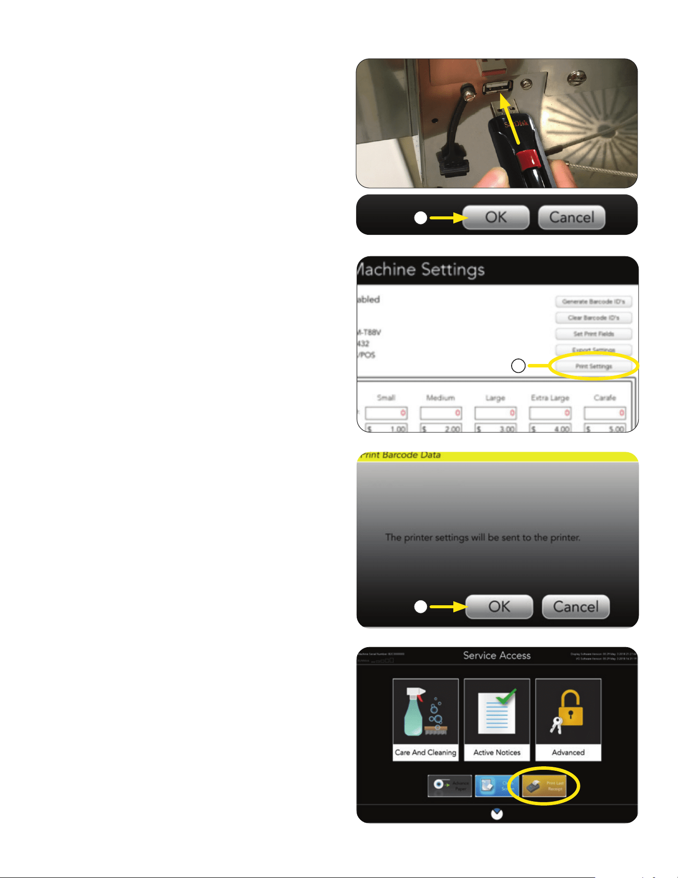
2. Insert the USB stick into the port.
3. Press OK.
4. The main screen will return.
5. Remove USB stick.
6. Close door.
1. Printer setting can be sent to the printer by
pressing the PRINT SETTINGS button.
2. Press OK to print the printer settings.
On the SERVICE ACCESS panel, the last receipt
can be printed by pressing the PRINT LAST
RECEIPT button in the lower right.
BARCODE PRINTER SETUP
Print Settings
Print Last Receipt
1
3
2
continued >
34
FILTER PAPER REMOVAL
When the "Paper Take Up Roll Full" indication has
been reached, the machine will lock out brewing.
The spent paper must be removed.
NOTE: This only applies when the take-up roller
is used. This can be applicable for "through"
counter installations depending on how the site
prefers to dispose of the waste. Grounds plus
paper or separated for compost.
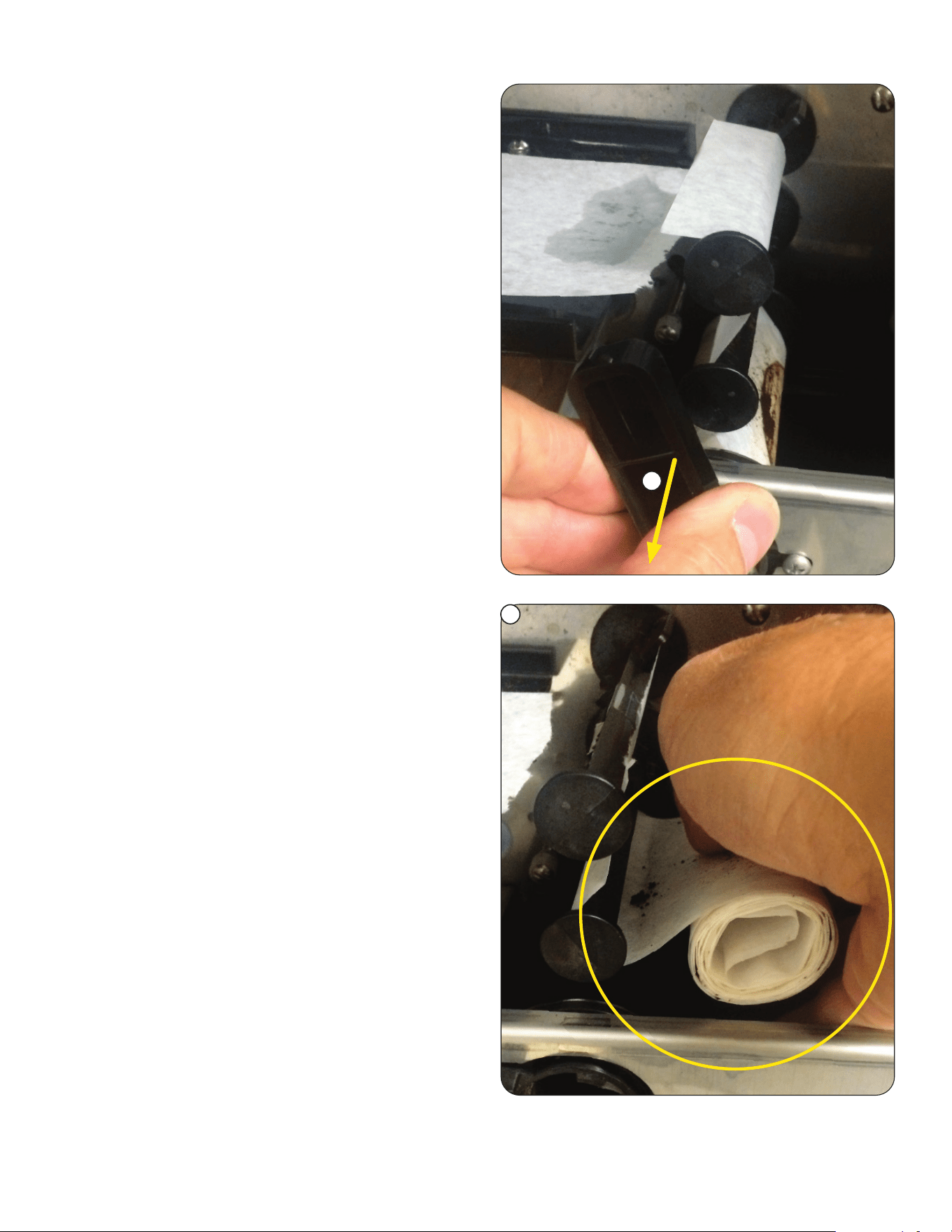
4. Turn the black take-up spindle handle up a
quarter turn.
1. To remove the used paper, press and
hold the BUNN logo icon at the top of
the screen for 3 seconds to access the
SERVICE ACCESS screen.
1
3. Open the brewer door and cut or tear the filter.
2. Press and hold the ADVANCE PAPER button for
3 seconds to dispense all of the used grounds.
NOTE: THE DOOR MUST REMAIN CLOSED!
3
2
NOTE: Cutting a clean edge on the filter paper
(as shown) can make installation easier.
4
continued >
35
FILTER PAPER REMOVAL
6. Remove the used paper roll from the machine,
or push it into the grounds bin.
Continue to "Filter Paper Replacement" section
to reset the take-up roller.
5
6
5. Remove the take-up roller by pulling
straight out.
continued >
36
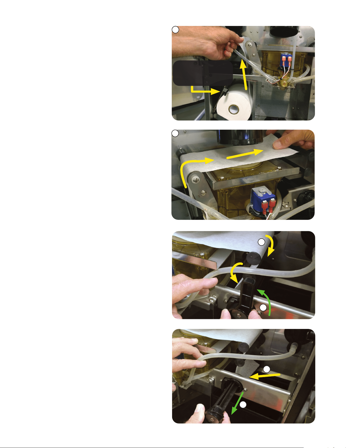
2. Pull end of paper between the Brew Funnel and
Brew Box.
3. Continue paper over the top spindle, then on the
left side of the middle spindle. Feed the paper
in front of the pick-up (bottom) spindle with the
handle.
FILTER PAPER REPLACEMENT
5. Pull the handle out as shown.
If you are starting with a new paper roll, start here.
If you are continuing with a partial roll that you cut at
the top spindle (shown previously), go to step 2.
1. Install filter paper roll and then route the filter
paper through the tractor drive as shown.
Pull the end of the paper roll up, and over left
spindle.
THE PAPER WEIGHT
MUST BE ON TOP OF
THE ROLL
1
2
3
4
5
6
continued >
4. Flip the handle a quarter turn to the left.
6. Place the paper in the slot that goes the length
of the pick-up spindle.
37
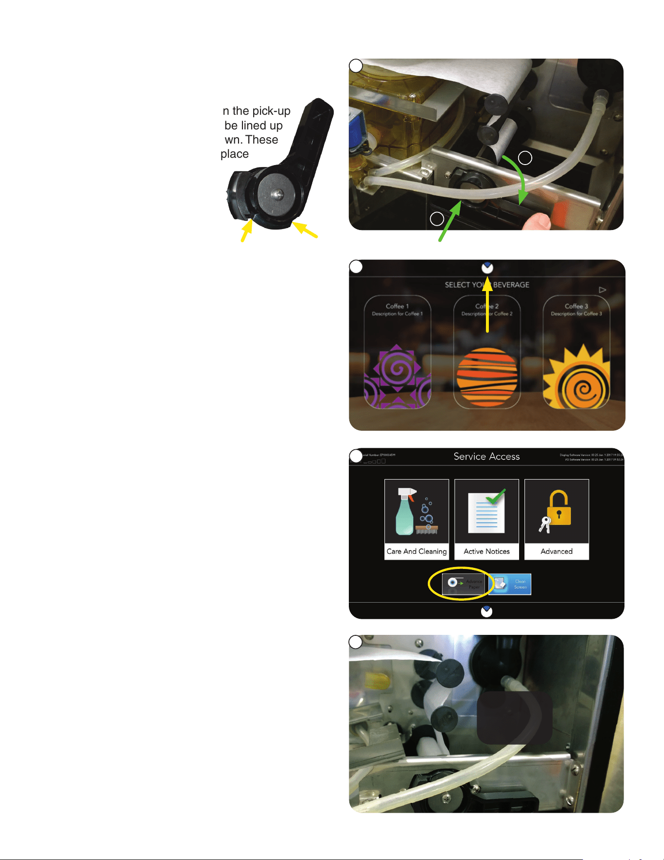
8. Close the door, and return to the SERVICE
ACCESS screen by pressing and holding
the BUNN logo at the top of the screen for
4 seconds.
9. Pressing and holding the ADVANCE PAPER
button will advance the paper to the proper
length.
READY
TO GO
10. Reopen the door to visually verify the filter
paper has advanced.
Close and lock the door to continue operation.
a
b
7. With the paper inserted into the slot of the
bottom spindle, a) push the spindle in,
b) then down a quarter turn to the right.
NOTE: There are notches on the pick-up
spindle handle that need to be lined up
before pulling the handle down. These
notches hold the handle in place
when the automatic paper
advance is in use.
FILTER PAPER REPLACEMENT
7
10
8
9
38
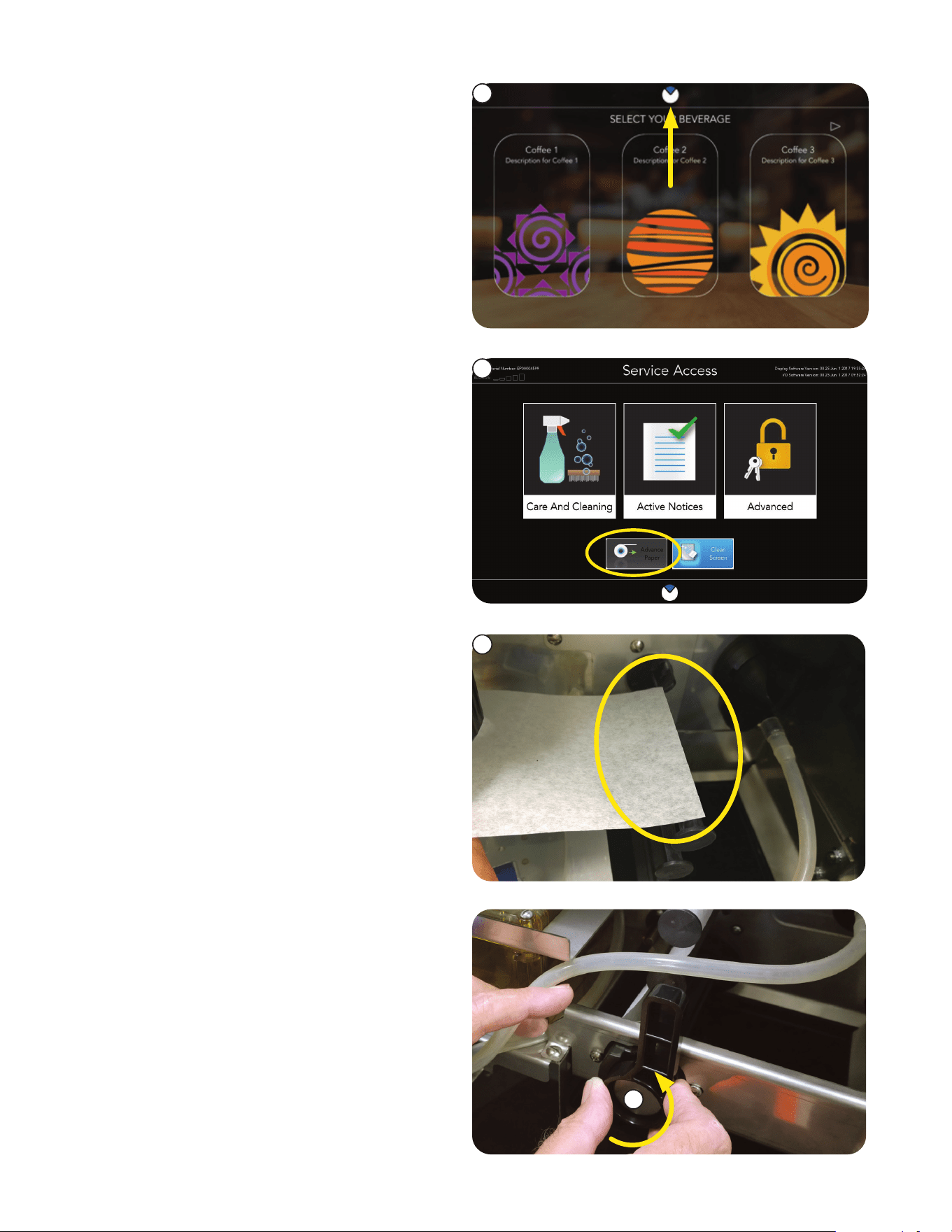
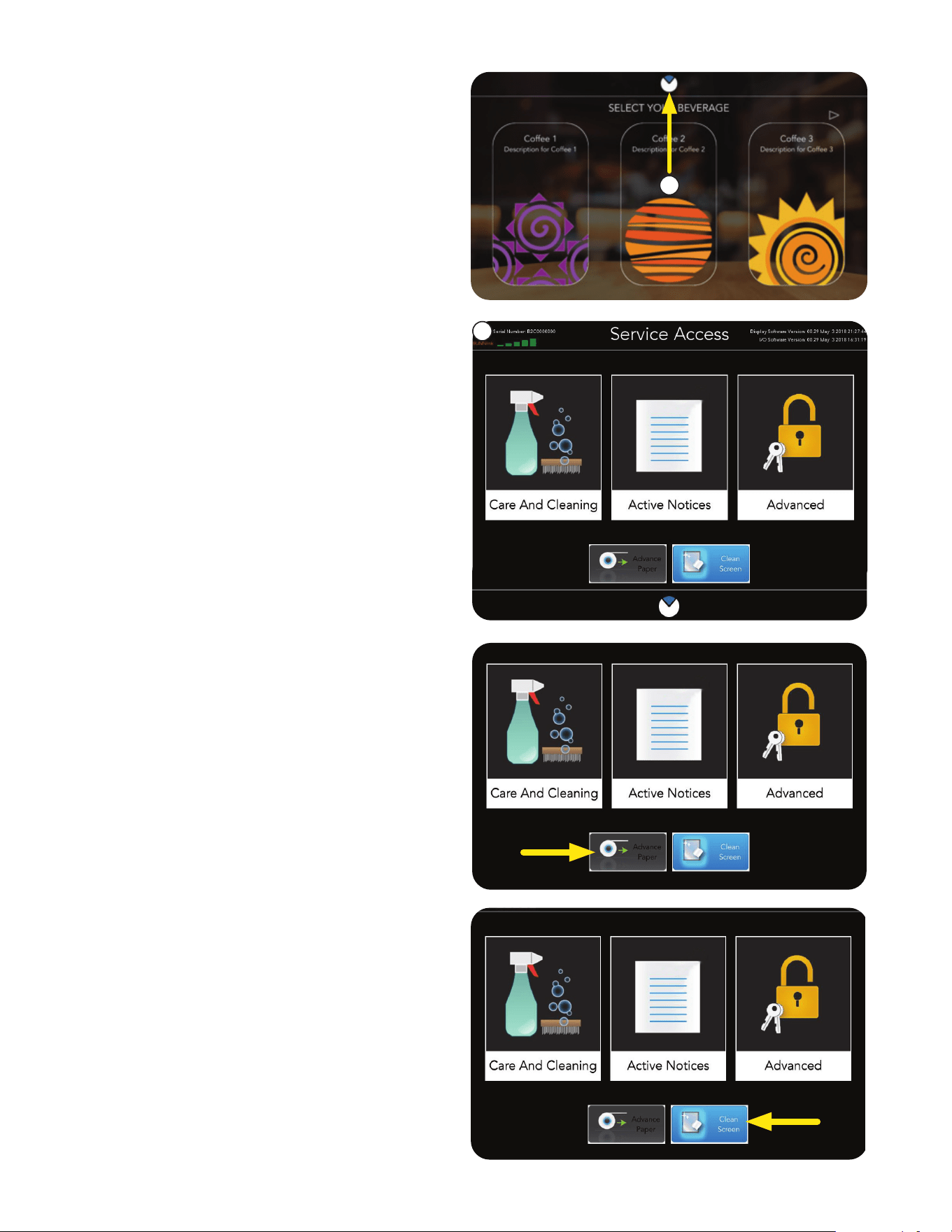
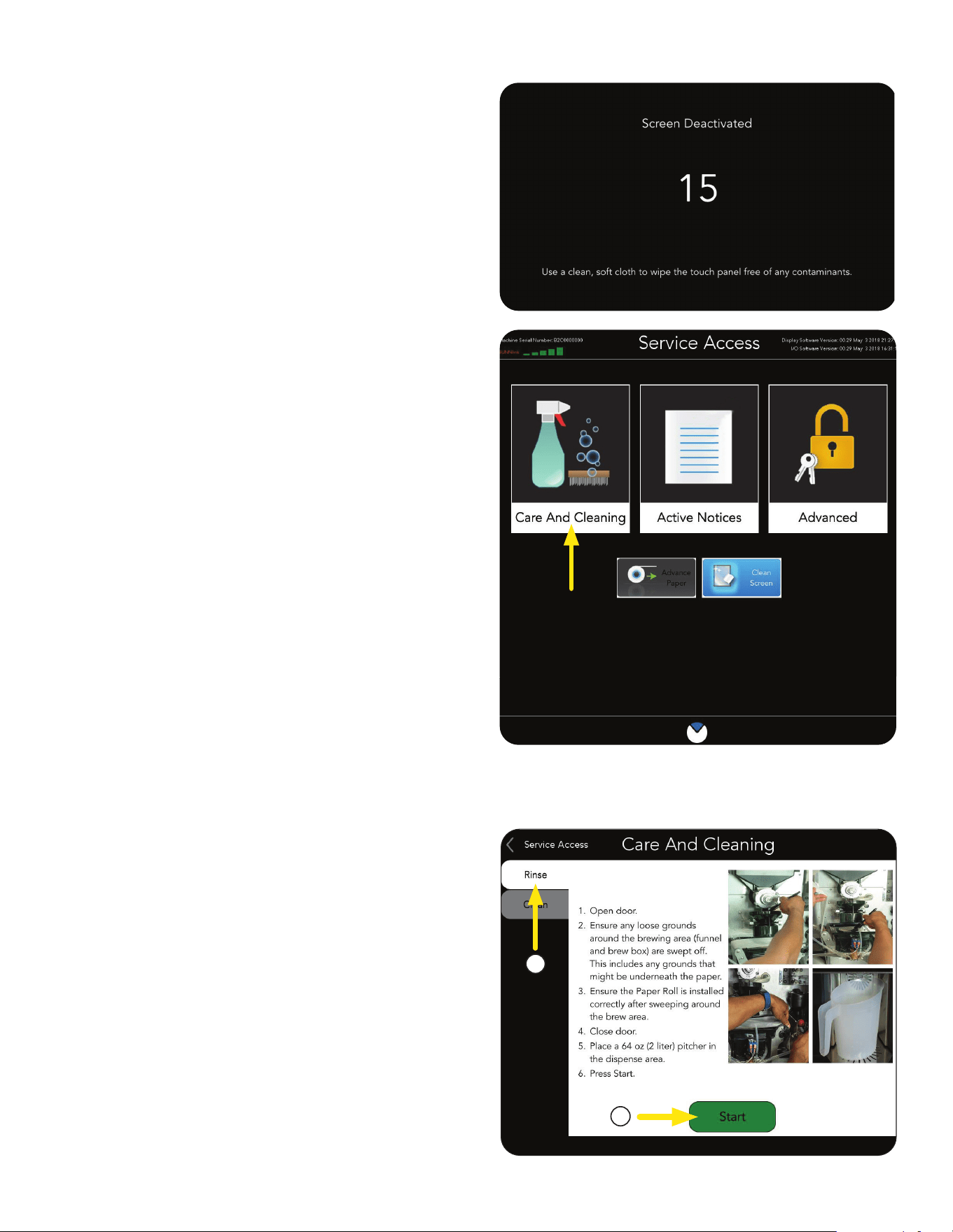
2. At the SERVICE ACCESS screen, the user has
access to CARE AND CLEANING, ACTIVE
NOTICES, ADVANCED screens as well as,
PAPER ADVANCE, and CLEAN SCREEN
functionality.
SERVICE ACCESS
Paper Advance Function
From the SERVICE ACCESS screen, the user can
ADVANCE PAPER. This function is necessary
during the emptying of the paper take-up spindle
and the reloading of filter paper.
Clean Screen Function
1. From the SERVICE ACCESS screen, the user
can utilize the CLEAN SCREEN function.
NOTE: Clean the screen with the provided micro
fiber cleaning cloth (PN 53465.0000)
2. Pressing the CLEAN SCREEN function button
deactivates the touch screen for 15 seconds.
1. Press and hold the BUNN logo at the top
of the screen for 3 seconds to access the
SERVICE ACCESS screen.
1
2
NOTE: For ADVANCED screen access, the user
will require security access pass codes. Please
check with your Manager or Supervisor for your
pass code.
NOTE: Pressing the BUNN icon at the bottom
of the screen will return the user to the main
screen.
continued >
39
Care and Cleaning
From the SERVICE ACCESS screen, press the
CARE AND CLEANING button.
Rinse Tab
1. Selecting the RINSE tab from the CARE
AND CLEANING screen will prepare the
equipment for rinsing the Brew Funnel and
Brew Box.
SERVICE ACCESS
3. A visual 15 second countdown is provided,
allowing the touch panel to be cleaned with-
out activating any other operation.
Parts Washing
1. Remove and wash the drip tray and drip tray
cover in a mild detergent solution. Rinse
thoroughly.
2. Wipe the lower front panel, door, and
cabinet with a clean damp cloth.
Exterior Surfaces:
• Do not use any abrasive materials.
• Use a soft, dry cloth, wipe down the exterior
surfaces of the dispenser to maintain the
luster of the finish.
• Wash the stainless steel interior surfaces of
the dispenser with warm, soapy water. Rinse
with warm, clear water. If the water is hard,
wipe the dispenser using a dry soft cloth, to
prevent spotting.
General Cleaning Note
The use of a damp cloth rinsed in any mild,
non-abrasive, liquid detergent is recommended for
cleaning all surfaces on Bunn-O-Matic equipment.
1
2
2. Press the START button.
Follow the directions shown on the screen.
DAILY
continued >
40
DAILY - Care and Cleaning (continued)
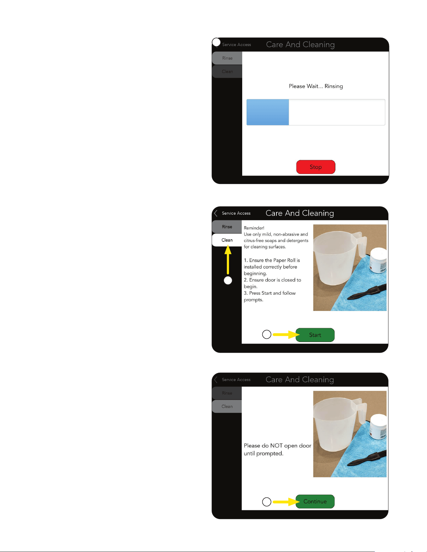
Rinse Tab
3. Once the START button has been pressed,
the CARE AND CLEANING screen will show a
progress bar - with the message "Please Wait -
Rinsing".
NOTE: If for any reason the rinsing process
needs to be halted, press the Stop button.
If the rinse is stopped before it is finished, the
Rinse cycle will need to be restarted to clear the
CUSTOMER CARE ALERT on the
information bar.
Clean Tab
1. Selecting the CLEAN tab from the CARE AND
CLEANING screen will prepare the equipment
for cleaning the Brew Funnel and Brew Box.
3. Once the START button has been pressed, the
CARE AND CLEANING screen will indicate
to the user to "Please do NOT open door until
prompted".
Press CONTINUE to move to the next step.
3
SERVICE ACCESS
WEEKLY
1
2. Press the START button to begin.
Follow the directions shown on the screen.
2
3
continued >
- Please Wait
41
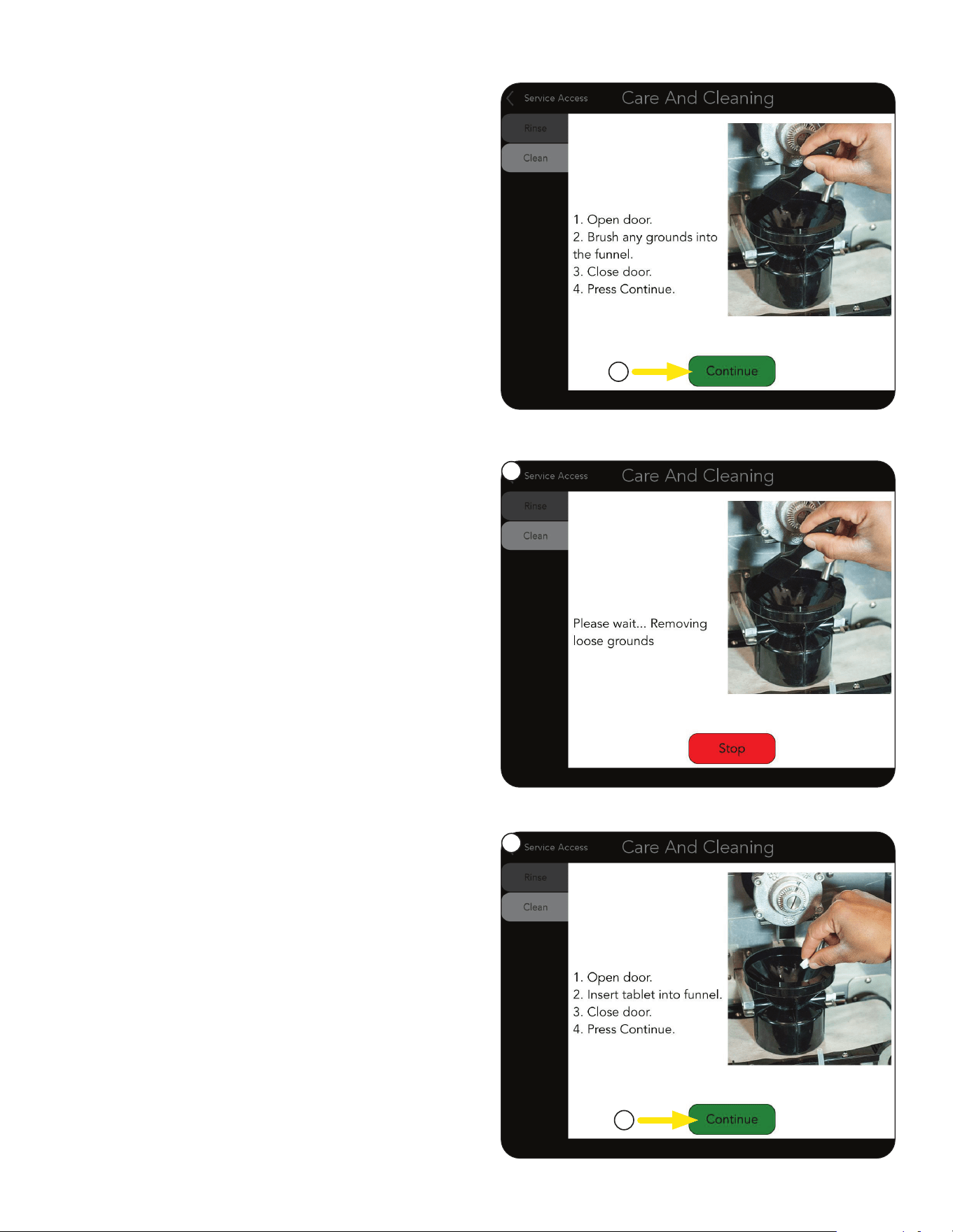
4. Follow the instructions.
Press CONTINUE.
5. The machine will begin rinsing any loose
grounds from the Brew Funnel.
Cleaning Tablets
After the Brew Funnel has been rinsed, the user will
be prompted with a new screen and directions.
SERVICE ACCESS
4
2
5
1
1. Following the steps to add a Cleaning Tablet.
2. Press CONTINUE button.
a. Open door.
b. Insert Cleaning Tablet into Brew Funnel.
c. Close door.
NOTE: Use only the cleaning tablets provided
with this unit. (PN 42933.0001)
continued >
42
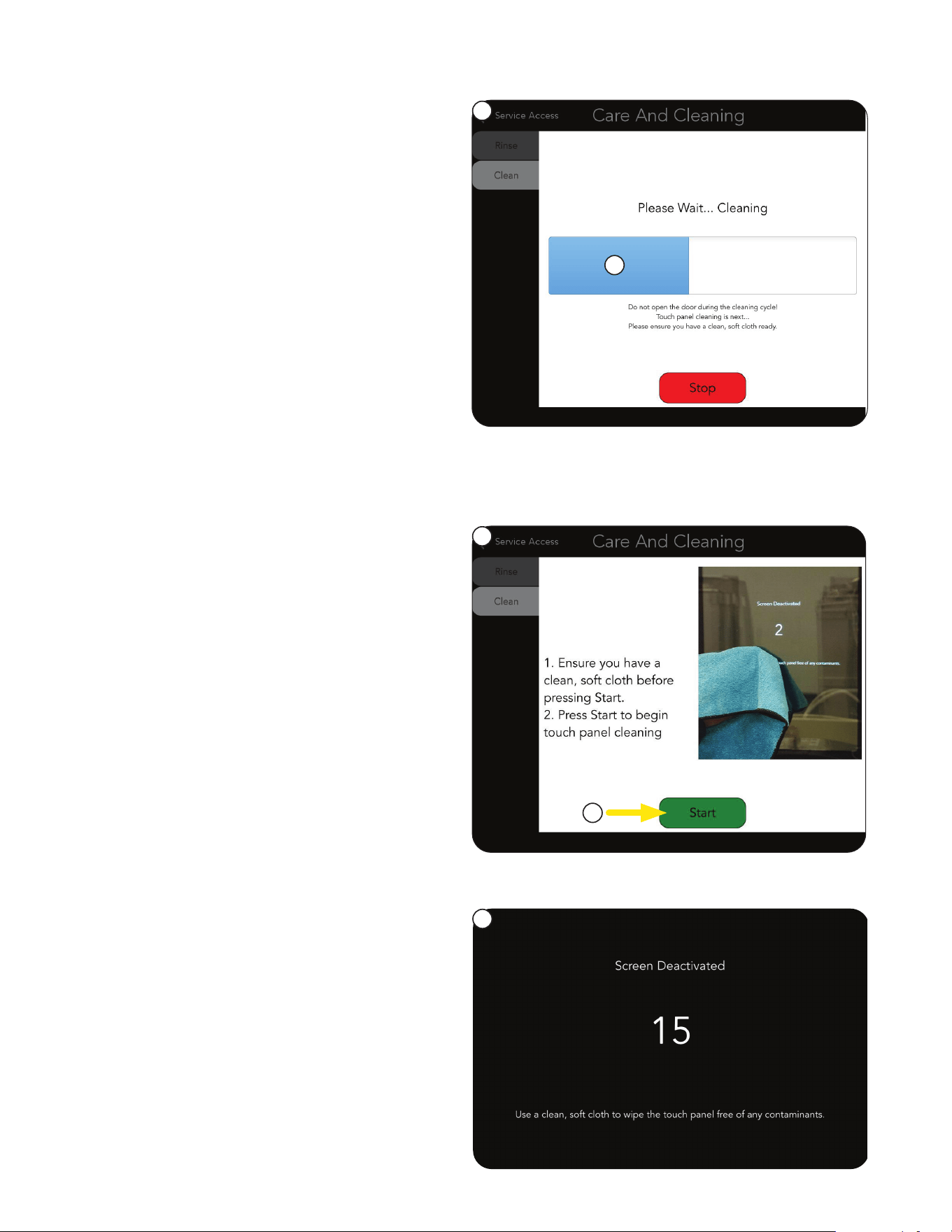
3. The machine will begin the cleaning cycle –
hot water will be added to the Cleaning Tablet,
dissolving it for use as a cleaning agent.
NOTE: The cleaning process can take up to
5 minutes to complete. If for any reason the
cleaning process needs to be halted, press
the STOP button.
If the STOP button is pressed any time during
the cleaning process, the clean cycle will be
halted and the machine will again prompt the
user "DO NOT PRESS STOP" – the machine is
resetting. The machine will rinse, then return to
the beginning CLEAN screen.
4. During the cleaning process, the user will be
provided with a progress bar and given a notice
regarding the next cleaning procedure
(Touch Panel Cleaning).
Cleaning Touch Panel
1. The final cleaning process is Touch Panel
Cleaning.
The user is prompted to have the provided
cloth ready before starting the next step.
2. Press the START button.
3. Once the START button has been pressed for
Touch Panel Cleaning, the touch panel is
deactivated for 15 seconds. During this time,
the screen will change and provide a countdown
allowing the touch panel to be cleaned
without activating any other operation.
After the touch panel cleaning reaches the end
of it's countdown, the machine resets and
returns to the main selection screen.
SERVICE ACCESS
WEEKLY
Cleaning Tablets (continued)
3
4
2
1
3
continued >
43
SERVICE ACCESS
Brew Funnel
The Brew Funnel can be removed for a more
thorough cleaning. This is recommended weekly or
more often if required (heavy usage of the machine).
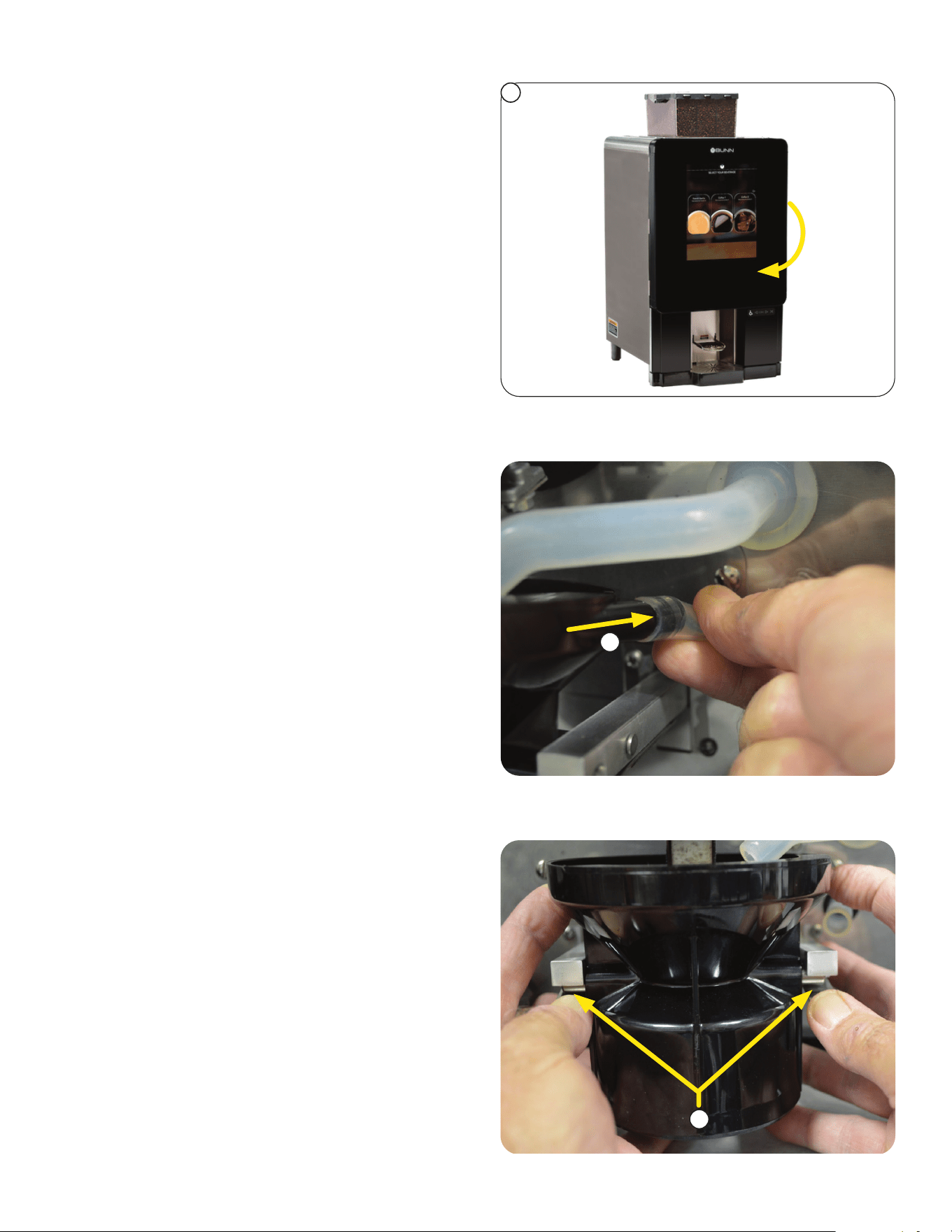
1. Open front door to remove Brew Funnel.
NOTE: Brew Funnel must be in the upper
position to be removed.
2
2. Slide the Rubber Hose (attached to the Brew
Funnel) towards the rear of the machine to
disconnect it from the Brew Funnel.
3. While pressing down on both Flat Springs
under the funnel arms, pull the funnel down
and forward to release it from the funnel arms.
3
1
continued >
- Removal & Washing
44
SERVICE ACCESS
WEEKLY
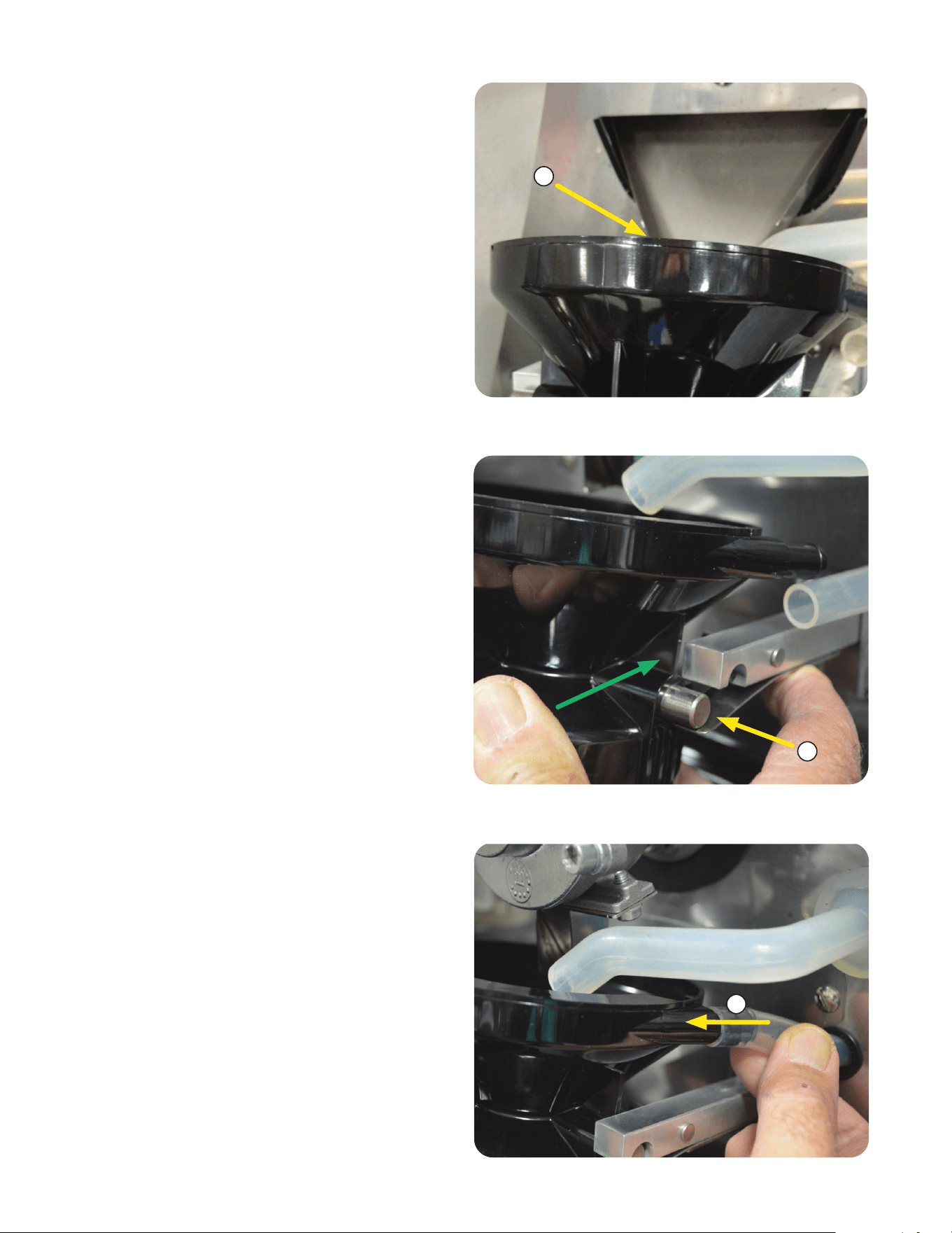
4. Clean the funnel using any mild, non-abrasive,
liquid detergent. Do Not use abrasives to clean
as this can damage the surface of the funnel.
Rinse and Dry.
7. Reconnect the Rubber Hose by sliding it over
the funnel inlet fitting.
NOTE: The hose must be fully engaged on
the fitting.
5. To reinstall the funnel, tip the top edge of the
funnel under the Coffee Chute.
5
6
6. Place the Metal Pins on the Flat Springs.
Push down and toward the rear of the machine
to snap the funnel into the Funnel Arms.
7
continued >
Brew Funnel Cleaning
(continued)
45
WEEKLY
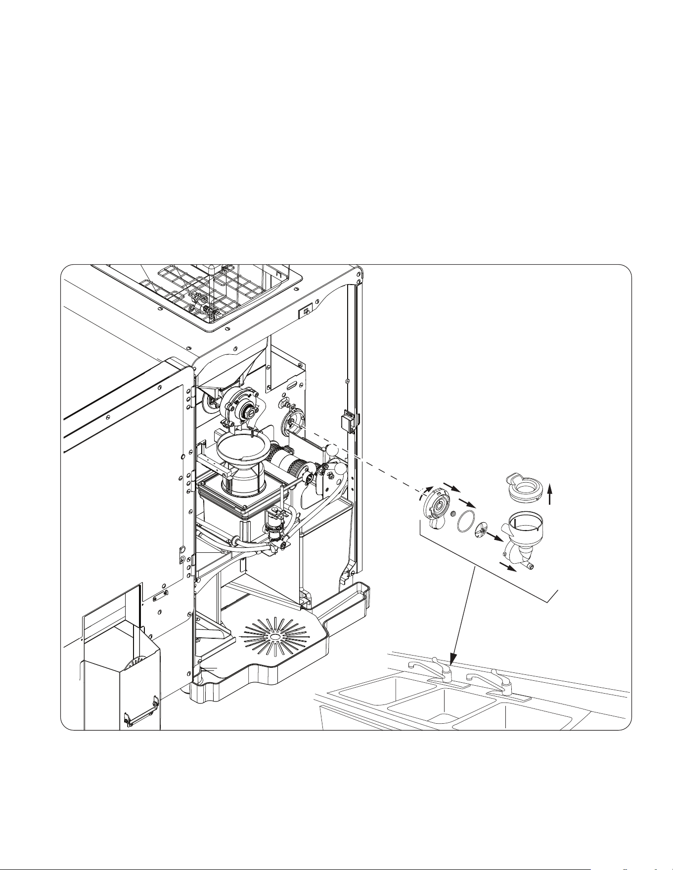
Mixing Chamber Parts Cleaning
• Remove the powder mixing chambers, steam traps, frothers and mixing chamber bases.
• Remove the dispense hoses from the dispense nozzle assembly.
• Clean all parts removed in warm soapy water. Use the provided cleaning brush (PN 26367.0000) to
clean bores and orifices. Rinse in cold water.
• Prepare one-gallon (3.8 liter) of sanitizing solution with at least 100 ppm of available chlorine in 120°F
(48.9°C) water. Soak all cleaned parts in sanitizing solution for 5 minutes, then allow to air dry.
• Rinse cleaning brush, dip in sanitizing solution, and brush the bore of dispense nozzles
NOTE: Repeat this procedure for each nozzle separately.
• When reassembling parts, be sure to align arrow on frother disk with flat on whipper motor shaft, and
rotate tab on whipper base clock wise to the vertical position to lock mixing chamber.
a
b
c
1
2
3
5
6
4
SERVICE ACCESS
8. Close the front door to resume normal operation.
continued >
Preventive Maintenance
There is a recommended PM kit available. Refer to the illustrated parts catalog on the BUNN website for the
Sure Immersion 312 to obtain part number for ordering:
- Sure Immersion 312 12-Month Preventive Maintenance Kit.
46
SERVICE ACCESS
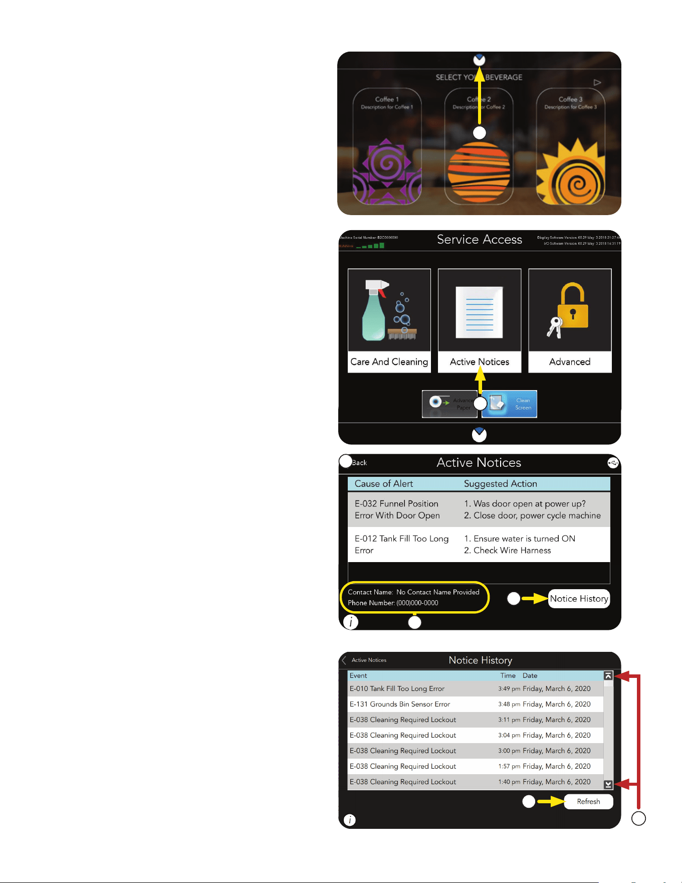
3. The ACTIVE NOTICES screen will display any
faults that have occurred by Name & Description,
and give probable causes, and a solution to
clear the fault.
4. A NOTICE HISTORY button is located in the
lower right portion of the screen, and can be
used to view previous events (Notices).
5. SERVICE CONTACT INFORMATION is
also provided.
Notice History
3
6. Use the Up or Down Arrows shown on the
right side of the screen to scroll through the
Events List.
7. Press the REFRESH button located in the
lower right portion of the screen to refresh
the list.
6
7
This screen will display the event name, the date
it occurred, what time of the day it occurred, how
many times it happened, and the machine's state.
4
5
Active Notices
1
2. From the SERVICE ACCESS screen, press the
ACTIVE NOTICES button.
2
1. Press and hold the BUNN logo at the top
of the screen for 3 seconds to access the
SERVICE ACCESS screen.
NOTE: Pressing the BUNN icon will return the
user to the main screen.
continued >
47
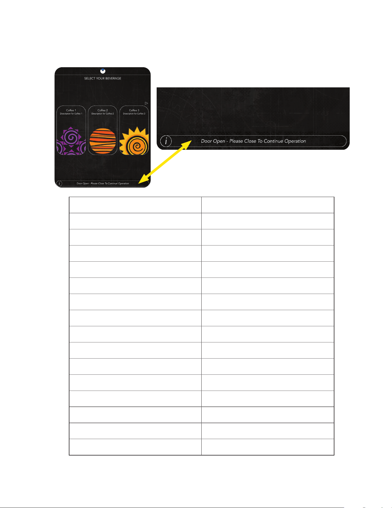
These alerts appear on the information bar at the bottom of the screen. They can be done by someone
without technical knowledge.
CUSTOMER CARE ALERTS RECOMMENDED STEPS
Brew Lockout Wait, Tank is Heating
Door Open Close to Continue Operation
Grounds Bin Not Detected Please Check Grounds Bin
Grounds Bin Full Empty the Grounds Bin
Grounds Bin Almost Full Empty the Grounds Bin
Check Left Hopper Fill with Beans
Check Center Hopper Fill with Beans
Check Right Hopper Fill with Beans
Out of Paper Replace Paper Roll
Check Paper, Full Roll Detected Empty Paper Take up Roller
Check Left Powder Hopper Fill with Powder
Check Right Powder Hopper Fill with Powder
Rinse Required Perform the Rinse Cycle
Clean Required Perform the Clean Cycle
Active Notices See Active Notice and Event Log Tile
Example of Information Bar
at bottom of screen showing alert.
SERVICE ACCESS
Customer Care Alerts