MILWAUKEE ELECTRIC TOOL CORPORATION
13135 W. Lisbon Road, Brookeld, WI 53005
Drwg. 3
BULLETIN NO.
54-24-2730
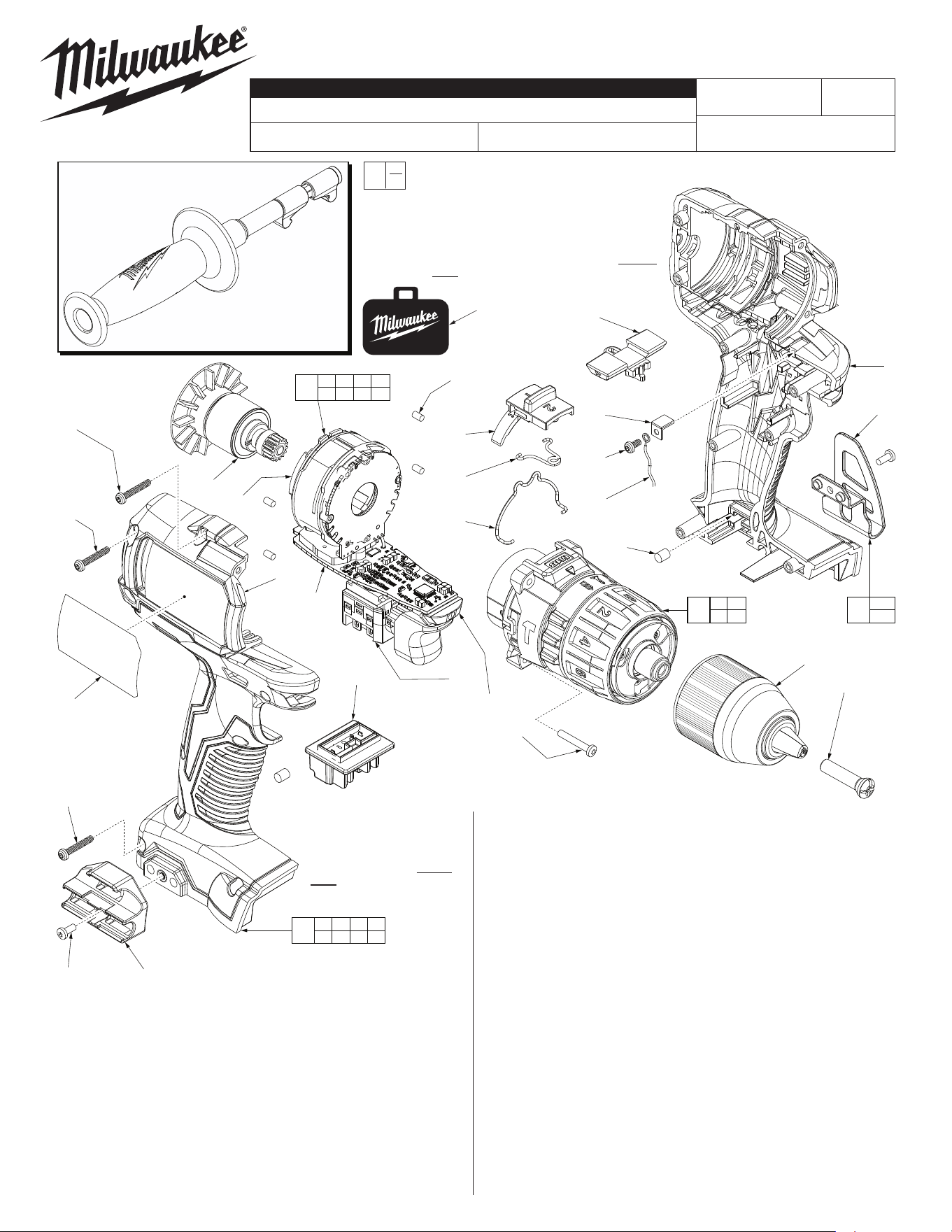
SERVICE PARTS LIST
FIG. PART NO. DESCRIPTION OF PART NO. REQ.
1 05-88-1500 M6 x 27mm LH Chuck Screw (1)
2 42-66-0023 1/2” Keyless Chuck (1)
3 06-82-0135 M3 x 18mm Pan Hd. Plastite T-10 Screw (4)
4 14-29-0052 Gearbox Assembly (1)
4a 45-24-2607 Speed Selector Slide (1)
4b 44-10-2607 Speed Change Lever (1)
4c 40-50-2607 Torsion Spring (1)
5 14-20-0037 Electronics Assembly
Consisting of: On-O Switch, PCBA, Stator,
LED Assembly, Battery Connector Block
and HV Contact Plate with Screw (1)
5a 06-82-0062 M3 x 8mm Pan Hd. T-10 ST Screw (1)
5b 40-50-0073 HV Contact Plate (1)
CATALOG NO. 2702-20
REVISED BULLETIN
SPECIFY CATALOG NO. AND SERIAL NO. WHEN ORDERING PARTS
M18™ Compact Brushless Hammer-Drill
STARTING
SERIAL NO.
DATE
Nov. 2018
WIRING INSTRUCTION
G40A
EXAMPLE:
Component Parts (Small #) Are Included
When Ordering The Assembly (Large #).
0
00
SEE PAGE 2
7g
(1x)
= Optional,
Not Standard
Equipment
5d
5e
3
(4x)
2
7e
5f
7b
(7x)
12
7a
10a(2x) 9
5h
5g
6
7c
(4x)
4a
4c
4b
7f
10b
1
8
5b
5a
5c
7d(2x)
7a 7b 7c 7d
7e 7f 7g
7
5a 5b 5c 5d
5e 5f 5g 5h
5
4a 4b
4c
4
10a
10b
10
Side Handle Assembly (Optional Equip.)
No. 14-34-0035
To reduce risk of
injury, always use a side
handle when using a 9.0 Ah or
higher battery to operate tool.
FIG. PART NO. DESCRIPTION OF PART NO. REQ.
5c --------------- HV Wire
(Component of Battery Connector Block)
(1)
5d --------------- On-O Switch (1)
5e --------------- LED Assembly (1)
5f --------------- PCBA (1)
5g --------------- Stator (1)
5h --------------- Battery Connector Block (1)
6 16-07-0057 Service Rotor Assembly (1)
7 31-44-0104 Housing Kit (1)
7a 06-82-5315 M3 x 26mm Pan Hd. T-10 Plastite Screw (1)
7b 06-82-6350 M3 x 16mm Pan Hd. T-10 Plastite Screw (7)
7c 45-30-2653 Rubber Slug - Stator Support (4)
7d 45-30-1000 Rubber Slug -
Battery Connector Block Support
(2)
7e --------------- Housing Halve - Right (1)
7f --------------- Housing Halve - Left (1)
7g 06-82-0135 M3 x 18mm Pan Hd. Plastite T-10 Screw (1)
8 42-42-0082 Forward/Reverse Shuttle (1)
9 43-72-0061 Bit Holder Kit (Optional) (1)
10 42-70-0101 Belt Clip Kit (Optional) (1)
10a 06-82-0130 6-32 x 5/16” Pan Hd. T-15 Screw (Optional) (2)
10b --------------- Belt Clip (Optional) (1)
11 42-55-2701 Blow Molded Carrying Case (1)
12 12-20-2701 Service Nameplate (1)
11
NOTE:
The design of Shuttle #8 is similar to other
tools that have a spring plate used in con-
junction with the shuttle. This tool DOES
NOT need a spring plate.
NOTE:
The design of Battery Connector
Block #5h is similar to other tools
that have a compression spring
used in conjunction with the
connector block for added
pressure. This tool DOES
NOT need a compression
spring.
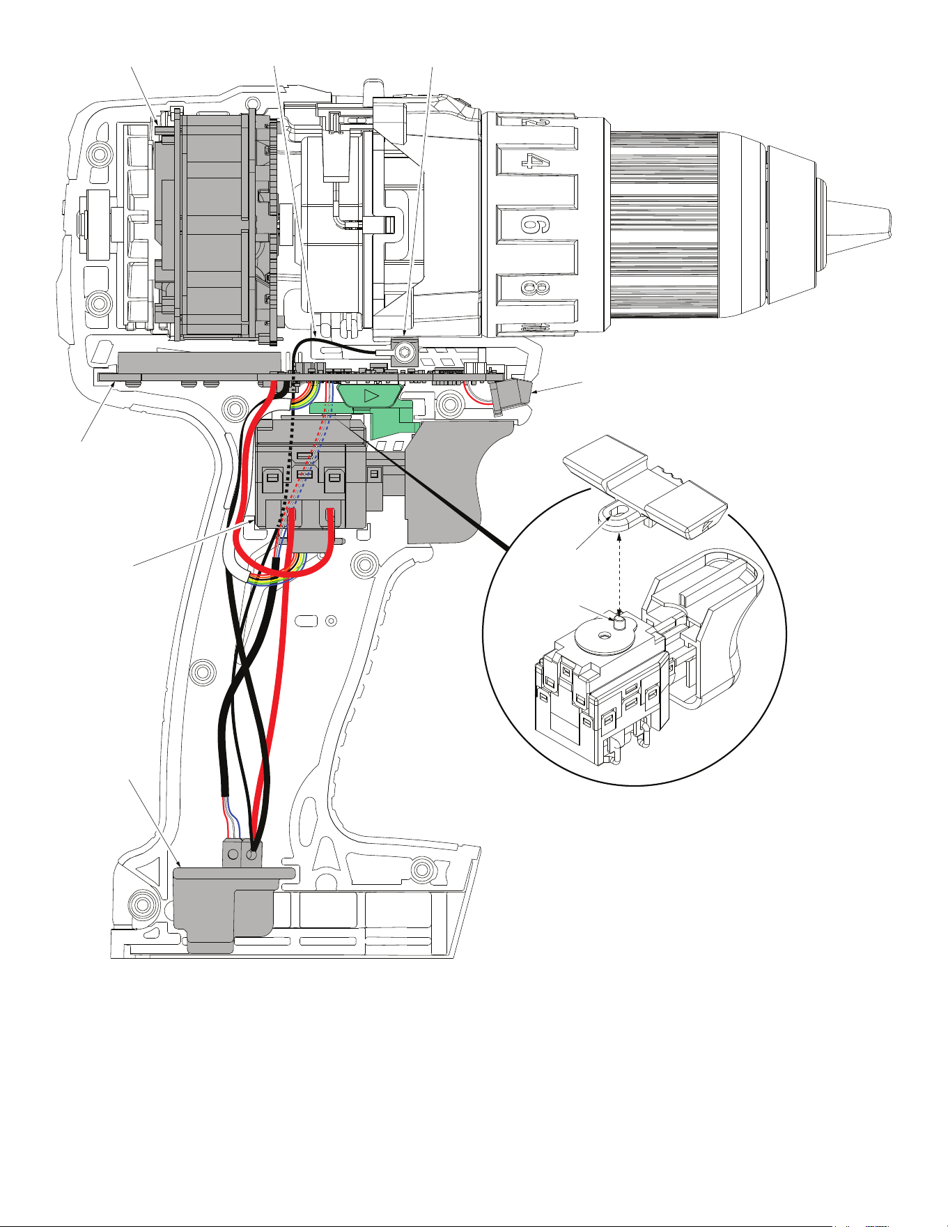
Shuttle Slot
Switch Post
Stator Assembly HV Wire Contact Plate
PCBA
On-Off Switch
Battery
Connector
Block Assembly
LED Assembly
AS AN AID TO REASSEMBLY, TAKE NOTICE OF WIRE ROUTING AND
POSITION IN WIRE GUIDES AND TRAPS WHILE DISMANTLING TOOL.
BE SURE THAT ALL COMPONENTS OF THE ELECTRONICS KIT
ARE SEATED FIRMLY AND SQUARELY IN THE HANDLE RECESSES.
AVOID PINCHED WIRES, BE SURE THAT ALL WIRES AND SLEEVES
ARE PRESSED COMPLETELY DOWN IN WIRE GUIDES AND TRAPS.
PRIOR TO INSTALLING THE HANDLE COVER ONTO THE HANDLE
SUPPORT, BE SURE THAT THERE ARE NO INTERFERENCES.
Be sure post in shift disc of switch is inserted
into slot of fwd./rev. shuttle when installing
electronics assembly. Check for proper
functionality prior to screwing
housing halves together.