
19a
19b
19
4c 4d 5 4g
4j
4h
7
8
11a
11b
13
14
15
16
17
19a
18
11e
9
11c
11d
23
12b
12a
10
4k
6
1
2
39
38
37
35
34
4a
4b
4e
4f
36
19b
20a
20b
21
22
24
25
26
30
29b
32
33
28
29a
4a 4b 4c 4d 4e
4f 4g 4h 4j 4k
4
20a
20b
20
12a
12b
12
11a 11b 11c
11d 11e
11
2
3
34 35 36
37 38 39
40
42
43
22 29a
22b
29
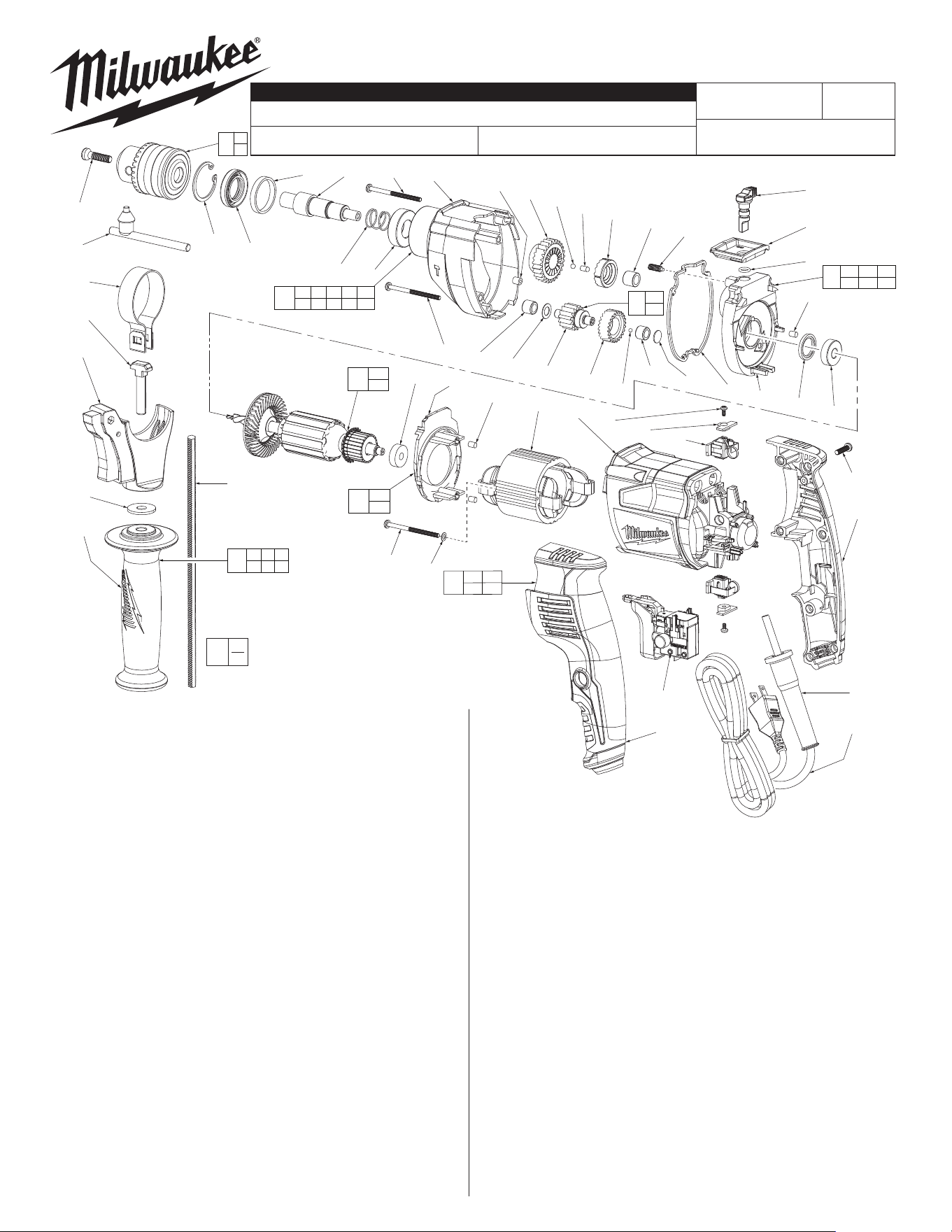
FIG. PART NO. DESCRIPTION OF PART NO. REQ.
1 05-88-1500 M6 x 1.0 x 27mm LH Screw (1)
2 48-66-3280 1/2" Chuck Key (1)
3 48-66-1355 1/2" Keyed Chuck (1)
4 28-14-5377 Gearcase Assembly (1)
4a 34-80-5380 Retaining Ring (1)
4b --------------- Oil Seal (1)
4c --------------- Plastic Ring (1)
4d --------------- Spindle (1)
4e --------------- Return Spring (1)
4f --------------- Ball Bearing (1)
4g --------------- Gearcase (1)
4h --------------- 2nd Stage Gear with Rotating Clutch (1)
4j --------------- Bushing (1)
4k --------------- Needle Bearing (1)
5 06-81-5380 M4 x 52 Pan Hd. ST T-20 Screw (2)
6 06-81-5383 M4 x 35 Pan Hd. ST T-20 Screw (1)
7 02-02-5380 Steel Ball (1)
8 44-60-5381 Pin (1)
9 43-44-5376 Rubber Gasket (1)
10 45-88-5381 Washer (1)
11 28-28-5376 Diaphragm Assembly (1)
11a --------------- Fixed Clutch (1)
11b --------------- Needle Bearing (1)
11c --------------- Washer (1)
11d --------------- Needle Bearing (1)
11e --------------- Diaphragm (1)
12 14-29-5376 Gear Shaft Assembly (1)
12a --------------- Gear Shaft (1)
12b --------------- 1st Reduction Gear (1)
13 44-70-5376 Spring Plunger (1)
14 44-10-5376 Selector Lever / Impact Pin Assembly (1)
15 42-92-5376 Selector Plate (1)
16 34-40-5376 O-Ring (1)
17 42-34-5380 Rubber Knock (1)
18 43-44-5377 Rubber Seal Ring (1)
19 16-07-5376 Armature Assembly (1)
19a 02-04-5381 Ball Bearing (1)
19b 02-04-5382 Ball Bearing (1)
20 14-34-5383 FanBaeAssembly (1)
20a --------------- Bae (1)
20b --------------- Rubber Knock (2)
54-24-3661
SERVICE PARTS LIST
BULLETIN NO.
EXAMPLE:
Component Parts (Small #)
Are Included When Ordering
The Assembly (Large #).
0
00
MILWAUKEE ELECTRIC TOOL CORPORATION
13135 W. LISBON RD., BROOKFIELD, WI 53005
Drwg. 2
FIG. PART NO. DESCRIPTION OF PART NO. REQ.
21 18-07-5376 Field (1)
22 --------------- Motor Housing (1)
23 02-02-0165 Steel Ball (1)
24 06-81-5381 M3 x 6mm Pan Hd. Phillips ST Screw (2)
25 44-66-5379 Pressure Plate (2)
26 22-22-5380 Self-Stop Carbon Brush Assembly (1)
27 22-22-5381 Carbon Brush Assembly (1)
28 23-66-5381 Switch (1)
29 14-34-5378 Rear Handle Assembly (1)
29a --------------- Handle Halve - Left (1)
29b --------------- Handle Halve - Right (1)
30 05-88-1200 M4 x 16mm Pan Hd. ST T-20 Screw (7)
32 44-76-0210 Cord Protector (1)
33 22-64-5378 Cord Set (1)
34 31-05-5383 Side Handle (1)
35 45-88-5377 Steel Washer (1)
36 44-94-5381 Depth Gauge (1)
37 14-34-5374 Side Handle Carrier Assembly (1)
38 05-81-5376 M8 x 53mm Screw (1)
39 40-50-5375 Side Handle Clamping Band (1)
40 14-34-5388 Side Handle Assembly (1)
41 12-20-5379 Service Nameplate (Not Shown) (1)
42 06-81-5385 Field Screw (2)
43 45-88-5400 Field Washer (2)
48-66-4040 Chuck Key Holder (Not Shown) (1)
23-94-5381 Red Brush Leadwire Assy. (Not Shown) (1)
23-94-5379 Black Brush Leadwire Assy. (Not Shown) (1)
«
CATALOG NO. 5376-20
REVISED BULLETIN
SPECIFY CATALOG NO. AND SERIAL NO. WHEN ORDERING PARTS
1/2" SINGLE SPEED HAMMER-DRILL
STARTING
SERIAL NO.
DATE
Aug. 2022
WIRING INSTRUCTION
D20B
SEE PAGE THREE
54-24-3660
«
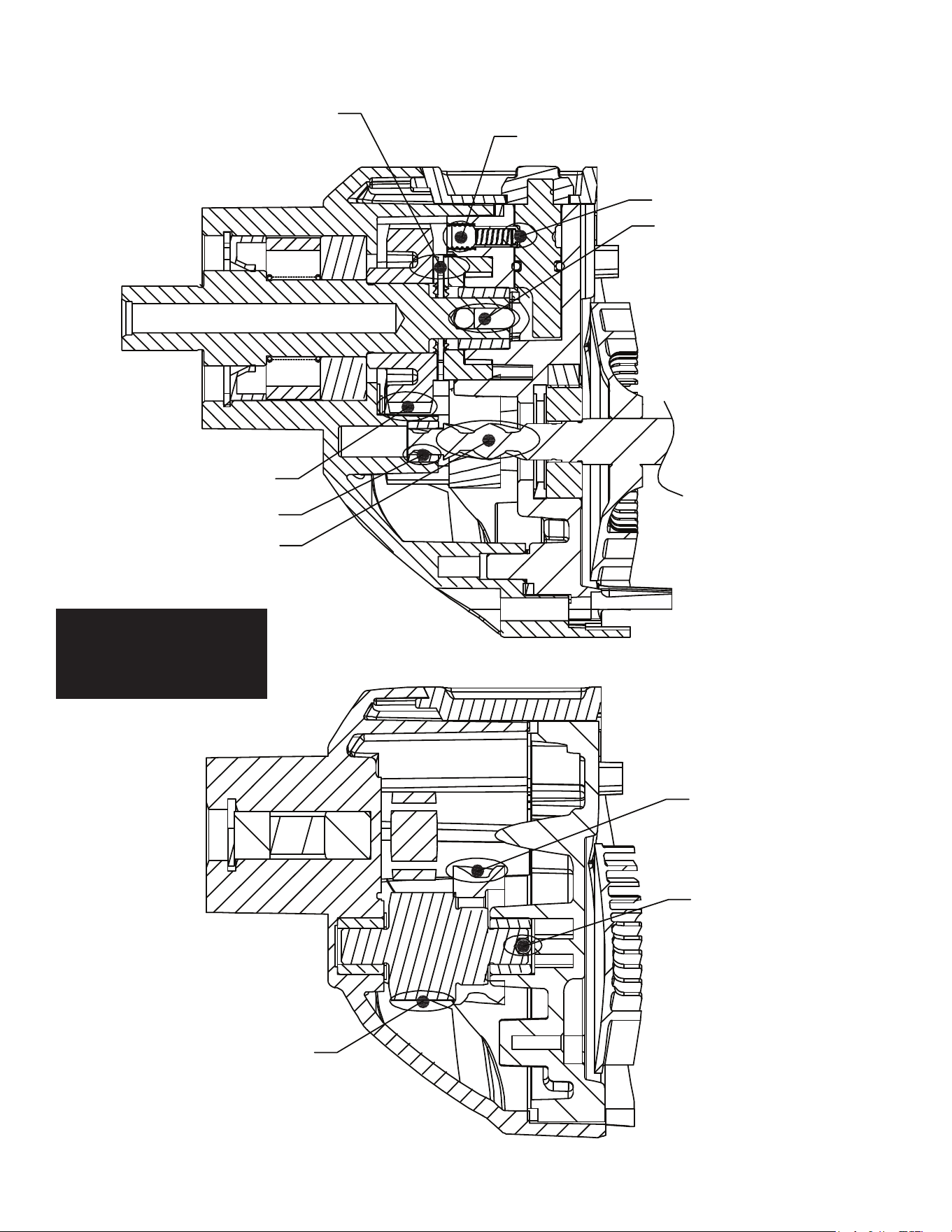
Brush 1g of grease
onto both clutch teeth
Coat all gear teeth with grease
Coat this area with grease
Coat this area of the
armature shaft with grease
Add a drop of purple Loctite® 222 here
Brush grease here
Place grease here
Place a heavy coating of grease
on all the gear shaft assembly teeth
Place a heavy coating of
grease on all gear teeth
Place grease in this area
Lubrication Notes:
Use Milwaukee 'P' Grease
Cat. No. 49-08-4250
When servicing, remove 90-95%
of the existing grease prior to
installing Type 'P' grease.
Original grease maybe similar in
color but not compatible with 'P'.
1/2" HAMMER-DRILL
DATE
MILWAUKEE ELECTRIC TOOL CORP. 13135 WEST LISBON RD. BROOKFIELD, WIS.
BULLETIN
WIRING INSTRUCTIONS
TITLE
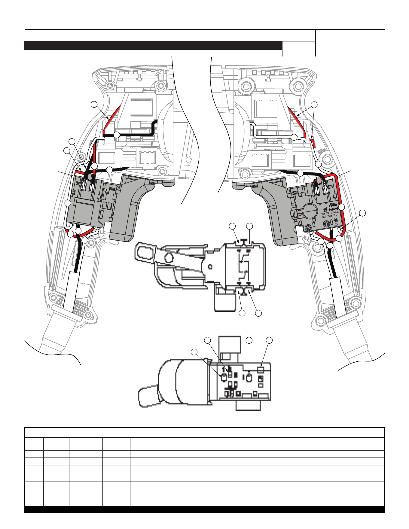
NOTE: As an aid to reassembly,
take note of the wire routings and
position of the wires in the wire guides
and traps prior to dismantling the tool.
Watch for pinched wires when placing
the handle cover back over the
housing assembly.
54-24-3661
Jan. 2014
Add shrinkable
tube to this red
wire
Add shrinkable
tube to this red
wire and lengthen
it from 100mm to
120mm
7
6
4
1
5
1
2
3
2
3
5
4
4
7
6
1
4
3
1
1 Red Switch ----- Connect from '5' on switch to '1a' on switch.
2 Black Field ----- Route from Field1 to '6' on switch.
3 Red 23-94-5381 ----- Connect to '4' on switch and route to top brush assembly.
4 White Field ----- Route from Field1 to '2a' on switch.
5 Black 23-94-5379 ----- Connect to '3' on switch and route to bottom brush assembly.
6 Black Cord ----- Connect to '2' on switch.
7 White Cord ----- Connect to '1' on switch.
Terminals, Connectors and 1 or 2 End Wire Preparation
Wire
Color
Origin or
Gauge
Wire
No.
Length
WIRING SPECIFICATIONS
BULK LEAD WIRE - BULLETIN NO. 58-01-0003
Top View of Switch
Bottom View of Switch
7
1
6 4
23
1
5