
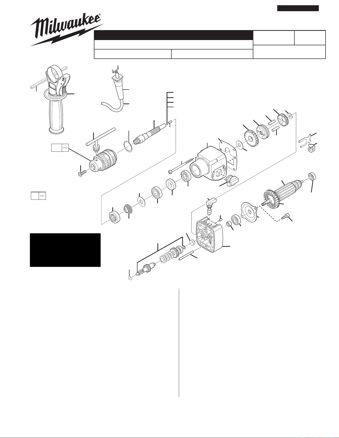
SPECIFY CATALOG NO. AND SERIAL NO. WHEN ORDERING PARTS
1/2 " HAMMER DRILL
CATALOG NO. 5380-21
235
236
237
238
217
400
1207
234
215
216
219
234
212
218
220
214
213
201
211
208
222
207
206
210
209
209
221
227
228
410
107
109
106
111
108
110
112
240
226
801
701
229
605
705
4
1208
MILWAUKEE ELECTRIC TOOL CORPORATION
13135 W. Lisbon Road, Brookfi eld, WI 53005
Drwg. 4
54-24-5380
SERVICE PARTS LIST
BULLETIN NO.
0
00
EXAMPLE:
Component Parts (Small #)
Are Included When Order-
ing The Assembly (Large #).
PAGE 1 OF 2
B01A
REVISED BULLETIN
DATE
Mar. 2010
WIRING INSTRUCTION
58-01-5380
STARTING
SERIAL NUMBER
FIG. PART NO. DESCRIPTION OF PART NO. REQ.
4 22-64-0490 Cordset 1
106 16-07-0220 Armature 1
107 22-84-0940 Fan 1
108 02-04-1825 Ball Bearing 1
109 02-04-0064 Ball Bearing 1
110 45-22-0055 Sleeve 1
111 42-92-0070 Bearing Cover 1
112 05-81-0960 Screw 2
201 38-50-0042 Spindle 1
206 45-88-8295 Washer 1
207 40-50-8890 Spring 1
208 02-04-1830 Ball Bearing 1
209 44-84-0295 Ratchet 2
210 44-90-0004 Seal Ring 1
211 44-90-0365 Snap Ring 1
212 45-88-1300 Washer 1
213 32-75-1220 Spindle Gear 1
214 44-90-4505 Shift Ring 1
215 32-75-0070 Spindle Gear 1
216 45-88-8335 Washer 1
217 44-60-1490 Pin 1
218 44-10-0095 Shift Lever 1
FIG. PART NO. DESCRIPTION OF PART NO. REQ.
219 40-50-8355 Retaining Spring 1
220 42-70-0790 Shifting Clip 1
221 44-60-1470 Pin 1
222 05-81-0190 Screw 4
226 45-88-0315 Washer 2
227 44-40-0130 Switch Lever 1
228 44-60-1500 Pin 1
229 32-60-0110 Reduction Gear 1
234 44-60-1475 Pin 2
235 02-02-0110 Ball 4.0 mm 1
236 02-02-0115 Ball 3.8 mm 1
237 02-02-0125 Ball 3.6 mm 1
238 02-02-0105 Ball 3.4 mm 1
240 45-88-8345 Thrust Washer 1
400 31-40-0160 Gear Case 1
410 28-28-0030 Diaphragm Assembly 1
605 43-46-0172 Depth Gage 1
701 48-66-5185 1/2 in. Chuck and Key 1
705 49-15-5300 Side Handle 1
801 05-80-0470 Locking Screw 1
802 48-66-2110 Chuck Key 1
1207 43-44-0345 Gasket 1
1208 44-76-0290 Cord Strain Relief 1
SEE REVERSE SIDE
FOR SERVICE &
GREASE NOTES
802
802
701
801
116
113
115
129
118
1103
127
1205
1204
1204
1205
1204
1204
1102
1101
126
127
1103
130
115
105
123
123
120
120
121
1203
1103
1107
1204
1203
1206
3
114
125
135
1202
132
131
1201
1201
1200
1201 1202 1203 1204
1205 1206 1207 1208
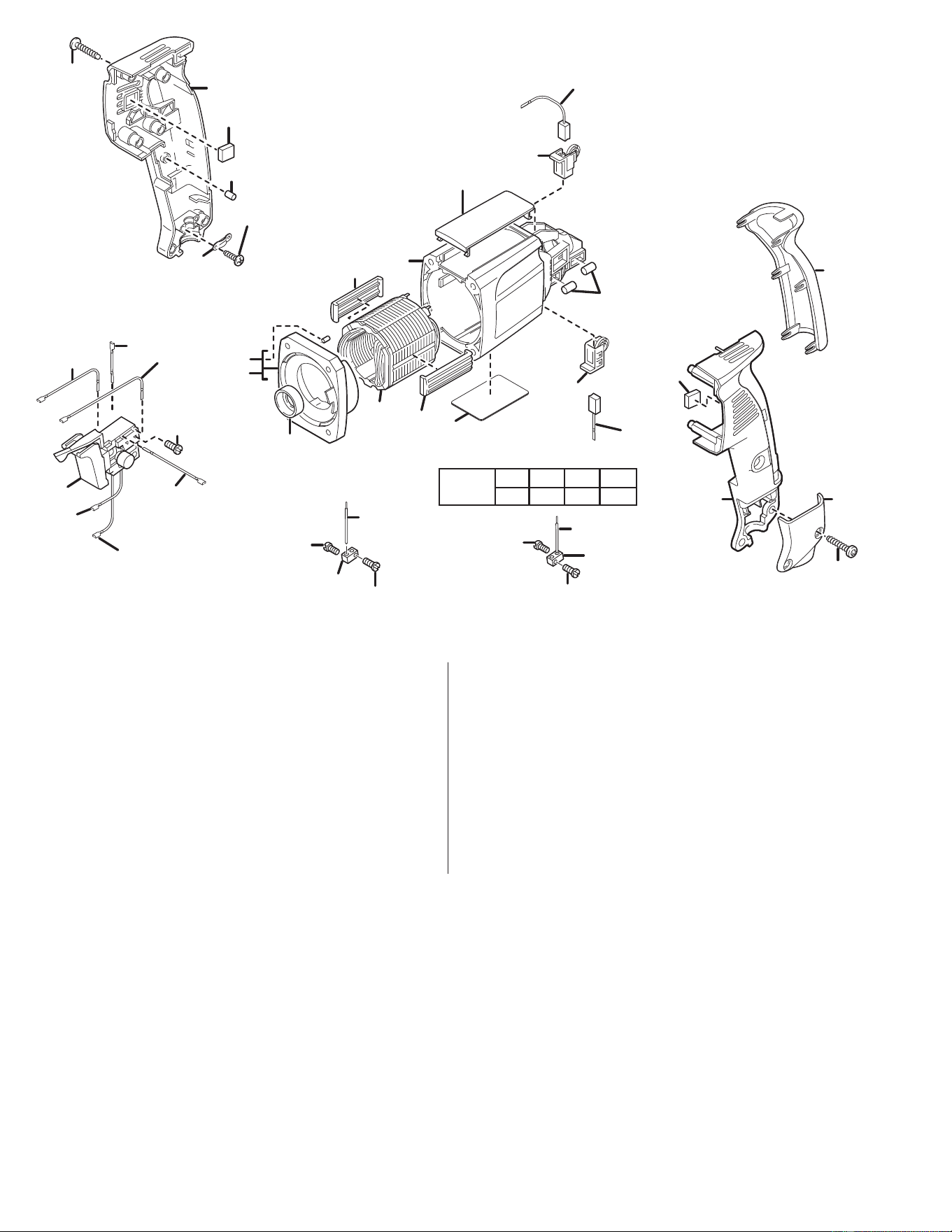
FIG. PART NO. DESCRIPTION OF PART NO. REQ. FIG. PART NO. DESCRIPTION OF PART NO. REQ.
3 12-20-5380 Service Nameplate 1
105 18-07-0180 Field 1
113 42-14-0430 Air Defl ection Ring 1
114 45-30-0210 Slug 4
115 23-94-6710 Wire 2
116 23-94-6715 Wire 1
118 23-94-6720 Wire 1
120 22-20-0232 Brush Holder 2
121 44-60-0915 Roller Pin 4
123 42-70-0030 Field Centering Clip 2
125 31-17-0240 Cord Clamp 1
126 05-78-0720 Screw 2
127 05-78-0715 Screw 6
129 23-94-6730 Wire 1
130 23-94-6735 Wire 1
131 23-94-6745 Wire 1
132 23-94-6740 Wire 1
135 23-66-0410 Switch 1
1101 31-50-0165 Motor Housing 1
1102 44-52-0030 Handle Cushion 1
1103 14-38-0110 Housing Assembly 1
1107 31-15-0160 Cover 1
1200 14-46-0090 Maintenance Set 1
1201 22-16-0025 Carbon Brush 1
1202 45-22-0540 Rubber Sleeve 1
1203 43-87-0085 Isolation Block 2
1204 05-81-0932 Screw 6
1205 42-86-0150 Connector 2
1206 45-30-0055 Slug 1
Service Notes
218, 227
Lubricate O-ring(s) on shifting levers (218 and 227) prior to assembly.
201, 235-238
The correct size ball (235-238) must be chosen to properly shim out the end play in the spindle (201).
Spindle is to have a small amount of end play without being tight.
801
Apply a drop of Blue Loctite® to locking screw (801) prior to installing into spindle.
229
Do not place clutch assembly (229) in solvent solution. Wipe off with a clean dry cloth.
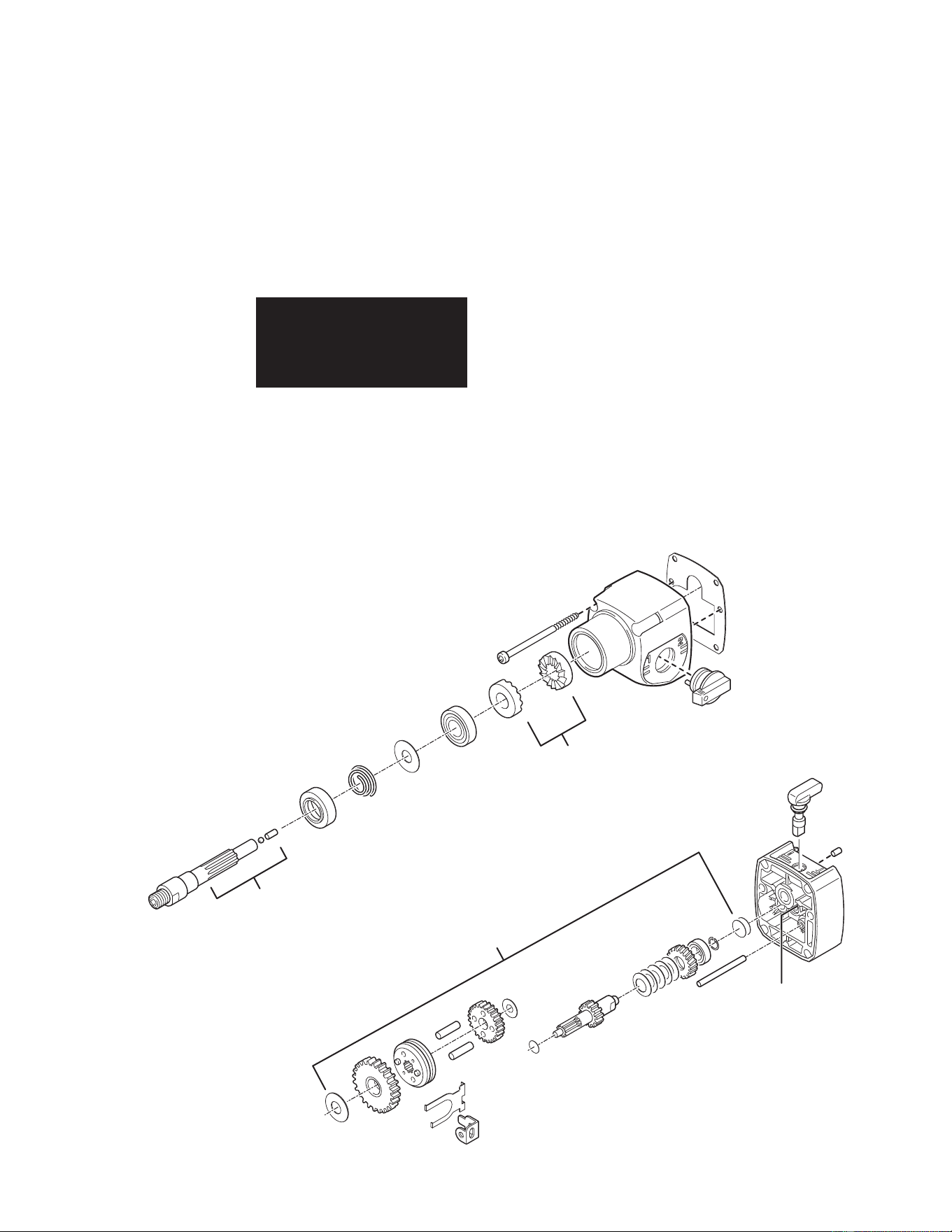
Greasing Instructions
Type “P” (49-08-4250)
Type “U” (49-08-0150)
1. Coat ratchets (209) with 1/16 oz. of Type “U” grease, No. 49-08-0150.
2. Coat spindle spline (201), pin (217) and ball (235-238) with 1/16 oz. of Type “P” grease, No. 49-08-4250.
3. Place 1/8 oz. of Type “P” grease, No. 49-08-4250, in fi rst reduction gear cavity in diaphragm (410).
4. Lubricate gear assembly (parts 212, 213, 214, 215, 216, 219, 220, 221, 226, 229, 234, and 240) using
1/4 oz. of Type “P” grease, No. 49-08-4250.
Total amount of lubrication: approximately 1/2 oz.
SERVICE PARTS LIST
1/16 oz. Type "P"
1/8 oz. Type "P"
1/16 oz. Type "U"
1/4 oz. Type "P"
When servicing, remove 90-95%
of the existing grease prior to
installing Type 'P' grease.
Original grease maybe similar in
color but not compatible with 'P'.