owner’s manual
v. BFCT1-030812
2
Table of conTenTs
I. BeFore You BegIn...........................................
II. IMPorTAnT SAFeTY InSTruCTIonS...............
III. FeATureS.............................................................
IV. dIMenSIonS.........................................................
V. ASSeMBlY InSTruCTIonS................................
VI. SeTTIng uP Your BFCT1.................................
VII. ConSole FeATureS..........................................
VIII. ConSole dISPlAY FeATureS..........................
IX. ConSole oPerATIon........................................
X. eXerCISe TIPS And guIdelIneS.....................
XI. TrouBleShooTIng...........................................
XII. SerVICIng The BFCT1......................................
XIII. hArdWAre...........................................................
XIV. hArdWAre lIST.................................................
XV. eXPloded VIeW dIAgrAM...............................
3
4
5
6
7 – 21
22 – 23
24
25
26 – 31
32 – 33
34
35
36 – 38
39 – 42
44 – 45
www.BestFitness.com

3
Thank you for purchasing the Best Fitness Cross Trainer BFCT1.
To maximize your use of the equipment please study this owner’s Manual thoroughly.
Unpacking the Equipment
The BFCT1 is carefully tested and inspected before shipment. We have shipped the unit in
several pieces that require assembly. Ask for assistance during the assembly process.
before You begin
Best Fitness equipment continually seeks ways to improve the performance, specifications and product manuals in order to ensure
that only superior products are released from our factories. Please take the time to carefully read through this manual thoroughly.
Instructions contained in this document are not intended to cover all details or variations possible with Best Fitness equipment, or to
cover every contingency that may be met in conjunction with installation, operation, maintenance or troubleshooting of the equipment.
even though we have prepared this manual with extreme care, neither the publisher nor the author can accept responsibility for any
errors in, or omission from, the information given. Should additional information be required, or should situations arise that are not
covered by this manual, the matter should be directed to your local Best Fitness equipment representative, or the Service department
at Best Fitness equipment in Forest Park, Illinois.
Any Questions?
Call (800) 556-3113

4
imporTanT safeTY insTrucTions
Before beginning any fitness program, you should obtain a complete physical
examination from your physician.
Il est conseille de subir un examen medical complet avant d’entreprendre tout programme d’exercise. Si vous avez des
etourdissements ou des faiblesses, arretez les exercices immediatement.
Antes de comenzar cualquier programma de ejercicios, deberias tener un examen fisico con su doctor.
WhEn Using ExErcisE EqUipmEnt, yoU shoUld alWays takE basic
prEcaUtions, inclUding thE folloWing:
read all instructions before using the BFCT1. These instructions are written to ensure your
safety and to protect the unit.
do not allow children on or near the equipment.
use the equipment only for its intended purpose as described in this guide. do not use ac-
cessory attachments that are not recommended by the manufacturer. Such attachments
might cause injuries.
Wear proper exercise clothing and shoes for your workout, no loose clothing.
use care when getting on or off the unit.
do not overexert yourself or work to exhaustion.
If you feel any pain or abnormal symptoms, stop your workout immediately and consult your
physician.
never operate the unit when it has been dropped or damaged. return the equipment to a
service center for examination and repair.
never drop or insert objects into any opening in the equipment.
Always check the unit before each use. Make sure that all fasteners are secure and in good
working condition.
do not use the equipment outdoors or near water.
pErsonal safEty dUring assEmbly
It is strongly recommended that a qualified dealer assemble the equipment. Assistance is
required.
Before beginning assembly, please take the time to read the instructions thoroughly.
read each step in the assembly instructions and follow the steps in sequence. do not skip
ahead. If you skip ahead, you may learn later that you have to disassemble components and
that you may have damaged the equipment.
Assemble and operate the BFCT1 on a solid, level surface. locate the unit a few feet from
the walls or furniture to provide easy access.
The BFCT1 is designed for your enjoyment. By following these precautions and using common
sense, you will have many safe and pleasurable hours of healthful exercise with your Best Fit-
ness BFCT1.
After assembly, you should check all functions to ensure correct operation. If you experience
problems, first recheck the assembly instructions to locate any possible errors made during as-
sembly. If you are unable to correct the problem, call the dealer from whom you purchased the
machine or call 1-800-556-3113 for the dealer nearest you.
•
•
•
•
•
•
•
•
•
•
•
•
•
•
•
5
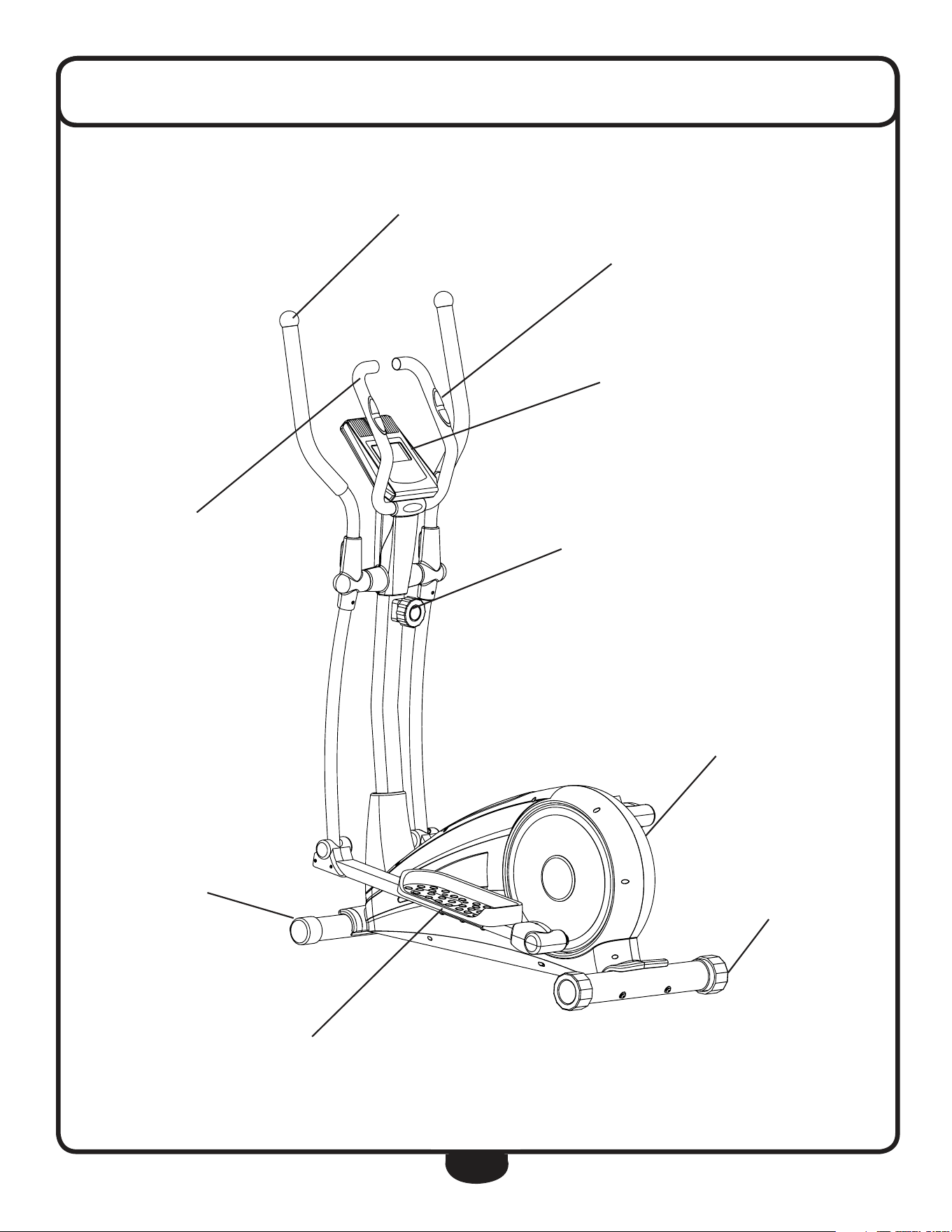
feaTures
CONTACT HEART RATE SENSORS
CONSOLE
TENSION ADJUSTMENT
FULLY SHROUDED FLYWHEEL
FOOT PLATE
ERGONOMIC HANDLE BARS
LEVEL STABILIZER
TRANSPORT WHEELS
STATIONARY HANDLE
6
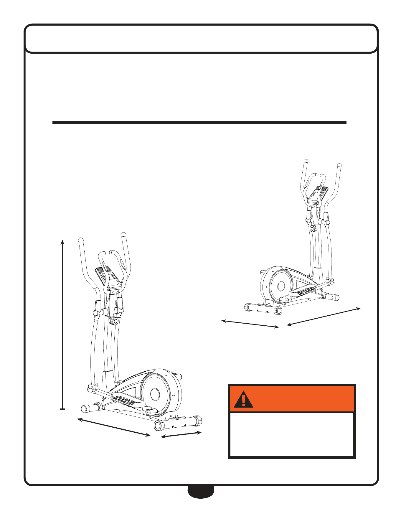
dimensions
5’ 5”
4’ 3”
1’ 9”
The room layout diagram below will help you decide the best placement for your BFCT1.
The dimensions of the BFCT1 are: Width 1’ 9” X length 4’ 3”.
The usage space is: Width 3’ X length 6’ (The usage space is the overall space needed for
operation).
The usage space needed for the BFCT1 could be more, depending on the user.
Minimum Usage Space
Suggested Usage Space
3’
6’
."9-0"%
-#,(
7!2.).'
250lb (113kg)
7
Assembly of the BFCT1 takes professional installers about 1/2 hour to complete. If this is
the first time you have assembled this type of equipment, plan on significantly more time.
Professional installers are highly recommended!
however, if you acquire the appropriate tools, obtain assistance, and follow the assembly
steps sequentially, the process will take time, but is fairly easy.
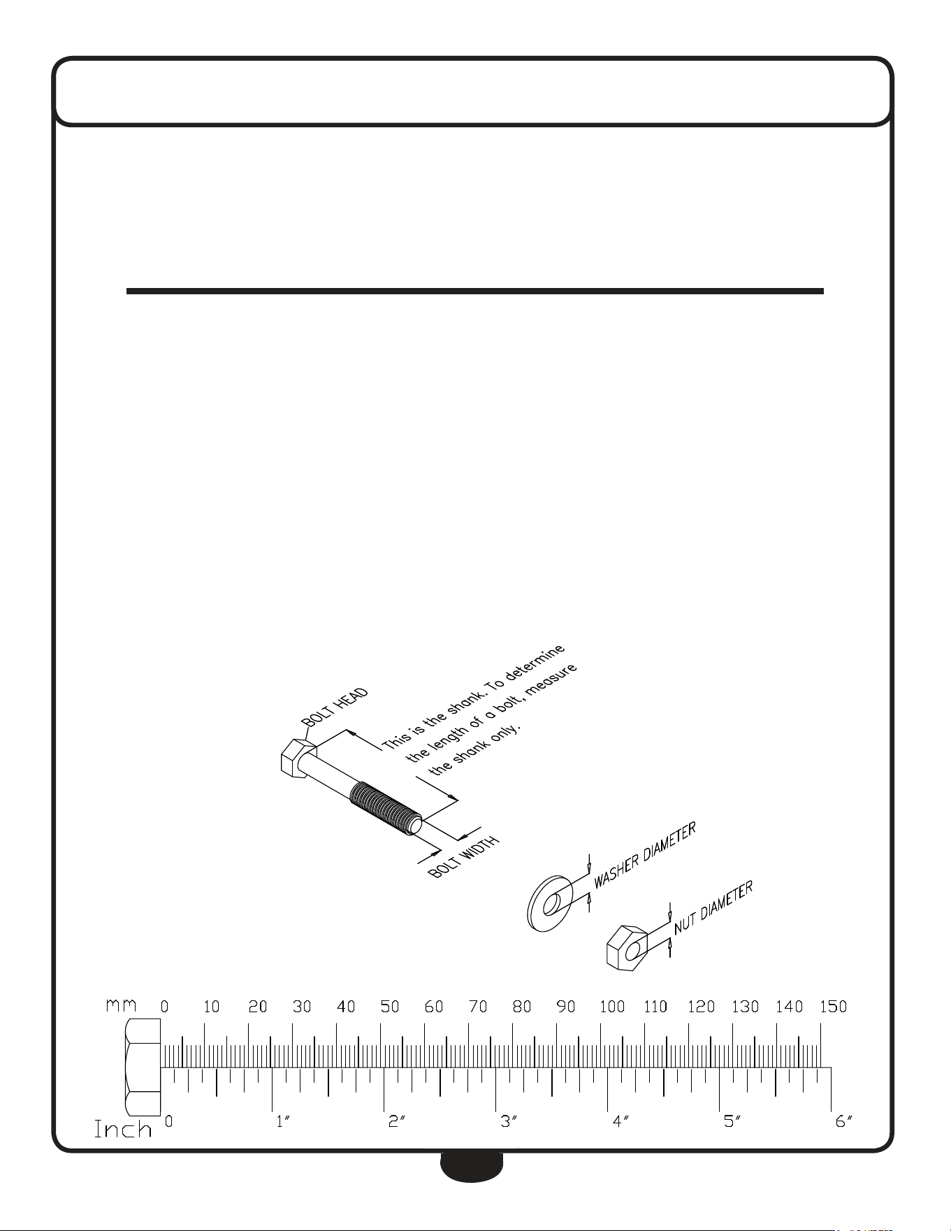
assEmbly tips
read all “notes” on each page before begin-
ning each step.
While you may be able to assemble the BFCT1
using the illustrations only, important safety
notes and other tips are included in the text.
Some pieces may have extra holes that you
will not use. use only those holes indicated in
the instructions and illustrations.
noTe: To find out the length of a particular
bolt, measure its shank (the long, narrow part
beneath the head).
refer to the following diagram:
*** Some of the hardwares
has been preinstalled.
noTe: After assembly, you should check all
functions to ensure correct operation. If you
experience problems, first recheck the assem-
bly instructions to locate any possible errors
made during assembly.
If you are unable to correct the problem, call
the dealer from whom you purchased the ma-
chine or call 1-800-556-3113 for the dealer
nearest you.
assemblY insTrucTions

8
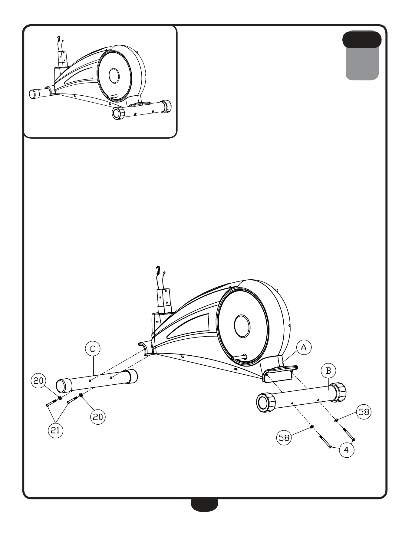
be careful to assemble all components
in the sequence they are presented.
1A. Connect rear leg (b) to Main Frame (a) using:
two 4 (m8x90mm round allen head bolt)
two 58 (m8x25mm arc Washer)
noTe: use the larger 8mm washer.
1B. Connect Front leg (c) to Main Frame (a) using:
two 21 (m8x72mm round allen head bolt)
two 20 (m8x19mm arc Washer)
noTe: use the smaller 8mm washer.
s T e p
1
9
s T e p
1
Above shows STeP 1 assembled and completed.
** Some of the hardwares
have been preinstalled.
10
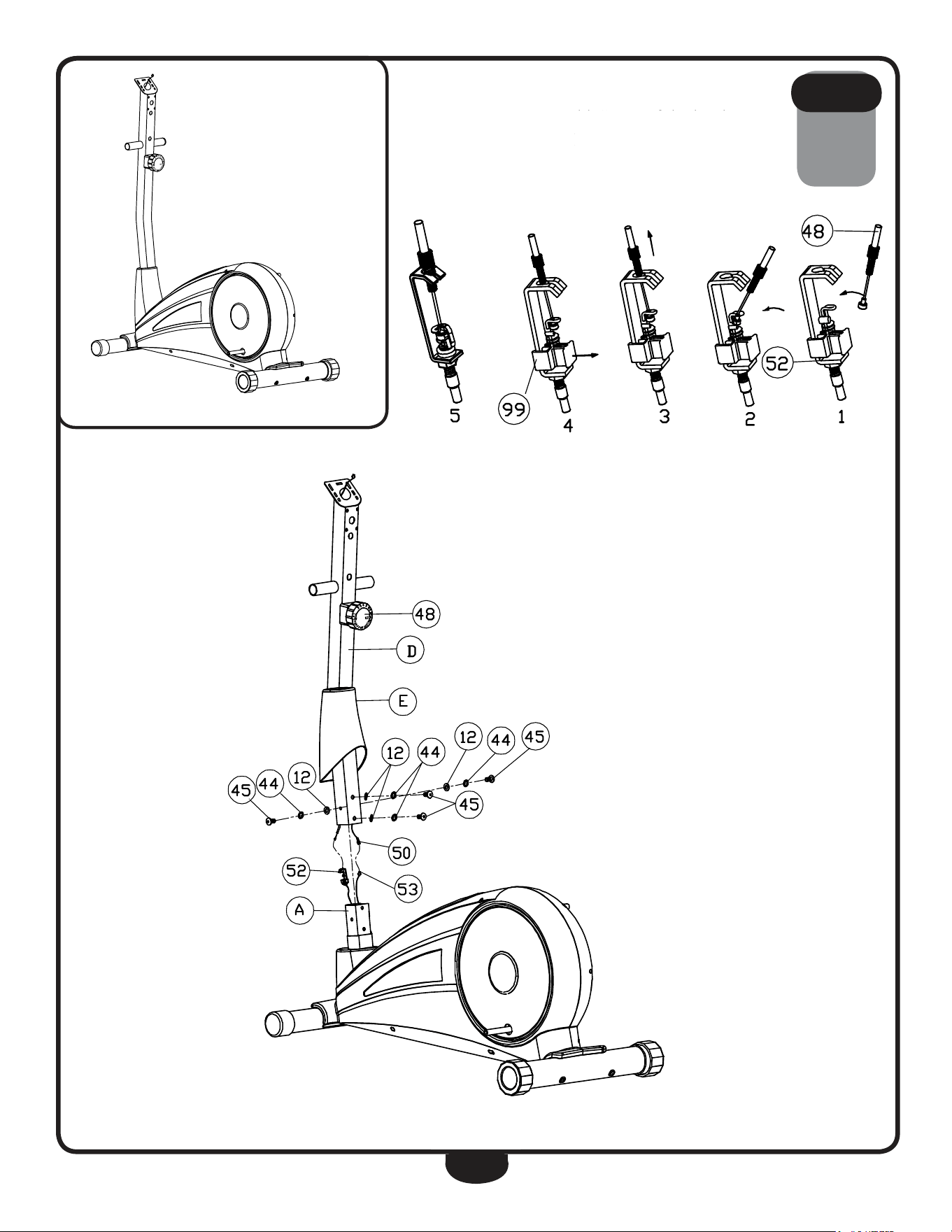
be careful to assemble all components
in the sequence they are presented.
2A. Slide Shroud (E) onto upright (d).
2B. Attach upper Tension Cable (48) to lower Tension Cable (52) as
shown in diagram 1. Push upper Tension Cable (48) towards lower
Tension Cable (52) as shown in diagram 2. Pull the cable up as shown in
diagram 3 then seat it in the slot. Pull out Plastic Component (99) as
shown in diagram 4.
2C. Connect upper harness (50) to lower harness (53).
2d. Slide upright (d) onto Main Frame (a) and secure using:
four 45 (m8x16mm round allen head bolt)
four 44 (m8 spring Washer)
four 12 (m8 Washer)
2e. let Shroud (E) slide to the bottom of upright (d).
s T e p
2
Warning
Do not force tension
caBle During installation.
! !
** Some of the hardwares
have been preinstalled.
** Some of the hardwares
have been preinstalled.
11
s T e p
2
Above shows STeP 2 assembled and completed.

12
be careful to assemble all components
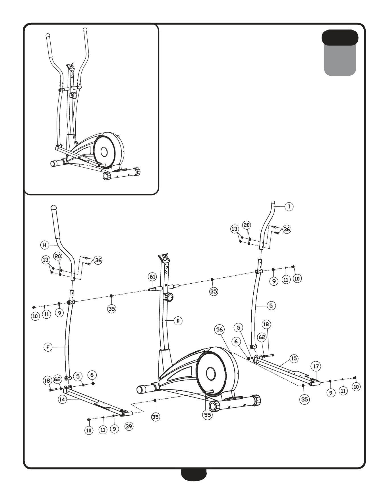
in the sequence they are presented.
3A. Insert both Shafts (61) into upright (d).
3B. Secure left Stride Bar (f) and right Stride Bar (g) onto upright (d) using:
two 10 (m10x20mm round allen head bolt)
two 11 (m10 spring Washer)
two 9 (m16.2 d-Washer)
two 35 (m17 Wave Washer)
3C. Secure left Foot Frame (14) onto left Crank (55) and right Foot Frame
(15) onto right Crank (56) using:
two 10 (m10x20mm round allen head bolt)
two 11 (m10 spring Washer)
two 9 (m16.2 d-Washer)
two 35 (m17 Wave Washer)
3d. Secure left Stride Bar (f) to left Foot Frame (14) using:
one 18 (Ø12x68xm10x12 hex head bolt)
one 62 (m12 Washer)
one 5 (m10 Washer)
one 6 (m10 nylon lock nut)
3e. Secure right Stride Bar (g) to right Foot Frame (15) using:
one 18 (Ø12x68xm10x12 hex head bolt)
one 62 (m12 Washer)
one 5 (m10 Washer)
one 6 (m10 nylon lock nut)
3F. Insert left handle (h) onto left Stride Bar (f) and secure using:
two 36 (m8x45mm carriage bolt)
two 20 (m8 arc Washer)
two 13 (m8 nylon lock nut)
3g. Insert right handle (i) onto right Stride Bar (g) and secure using:
two 36 (m8x45mm carriage bolt)
two 20 (m8 arc Washer)
two 13 (m8 nylon lock nut)
s T e p
3
13
s T e p
3
Above shows STeP 3 assembled and completed.
** Some of the hardwares
have been preinstalled.

14
be careful to assemble all components
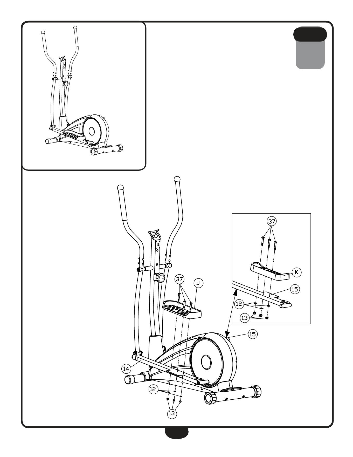
in the sequence they are presented.
4A. Connect left Foot Plate (J) to left Foot Frame (14) using:
three 37 (m8x45mm hex head bolt)
three 12 (m8 Washer)
three 13 (m8 nylon lock nut)
4B. Connect right Foot Plate (k) to right Foot Frame (15) using:
three 37 (m8x45mm hex head bolt)
three 12 (m8 Washer)
three 13 (m8 nylon lock nut)
s T e p
4
15
s T e p
4
Above shows STeP 4 assembled and completed.
** Some of the hardwares
have been preinstalled.

16
be careful to assemble all components
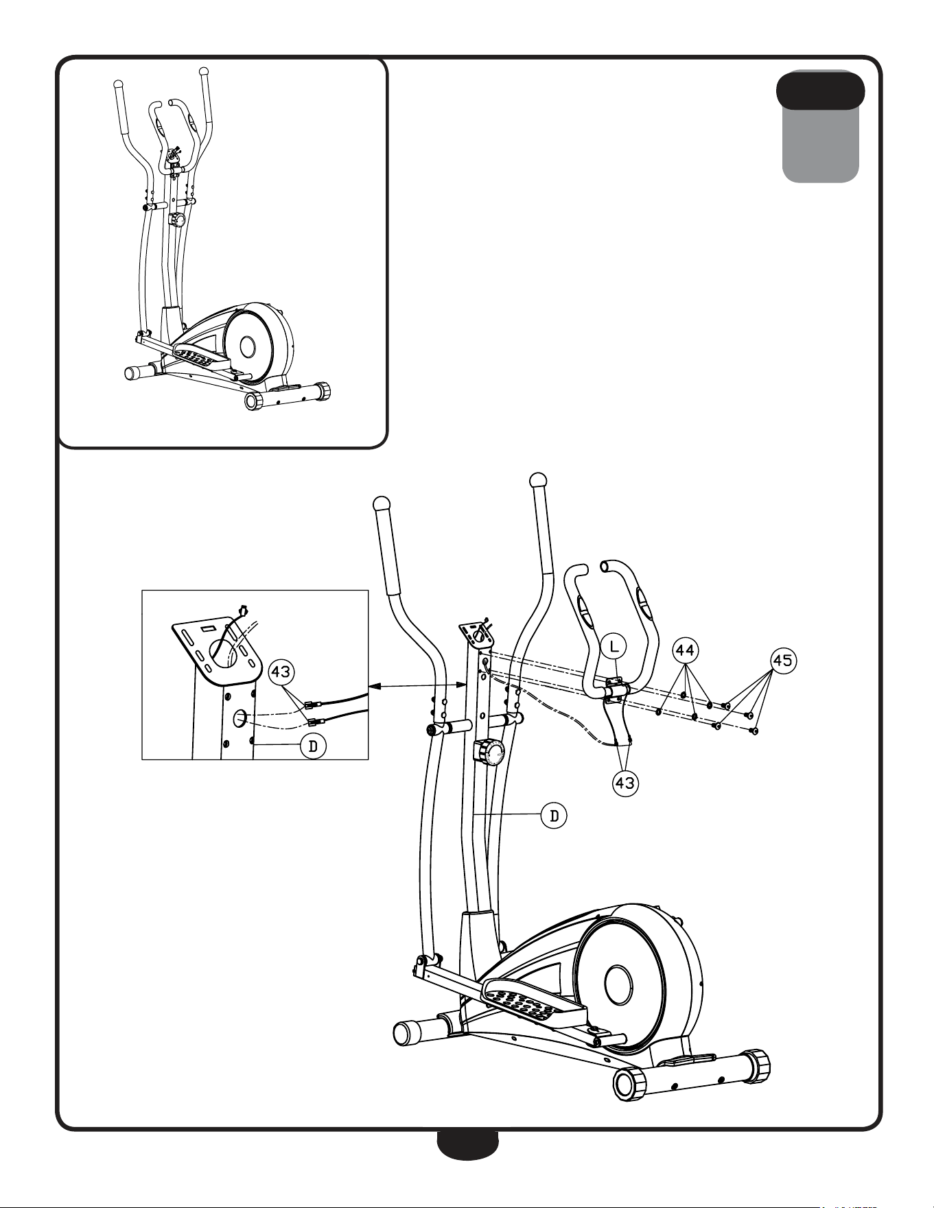
in the sequence they are presented.
5A. route upper Cable harnesses (43) through the hole in upright (d) then
up as shown. let upper Cable harnesses (43) hang from the top of
upright (d).
5B. Secure handle Bar (l) to upright (d) using:
four 45 (m8x16mm round allen head bolt)
four 44 (m8 spring Washer)
s T e p
5
17
s T e p
5
Above shows STeP 5 assembled and completed.
** Some of the hardwares
have been preinstalled.

18
be careful to assemble all components
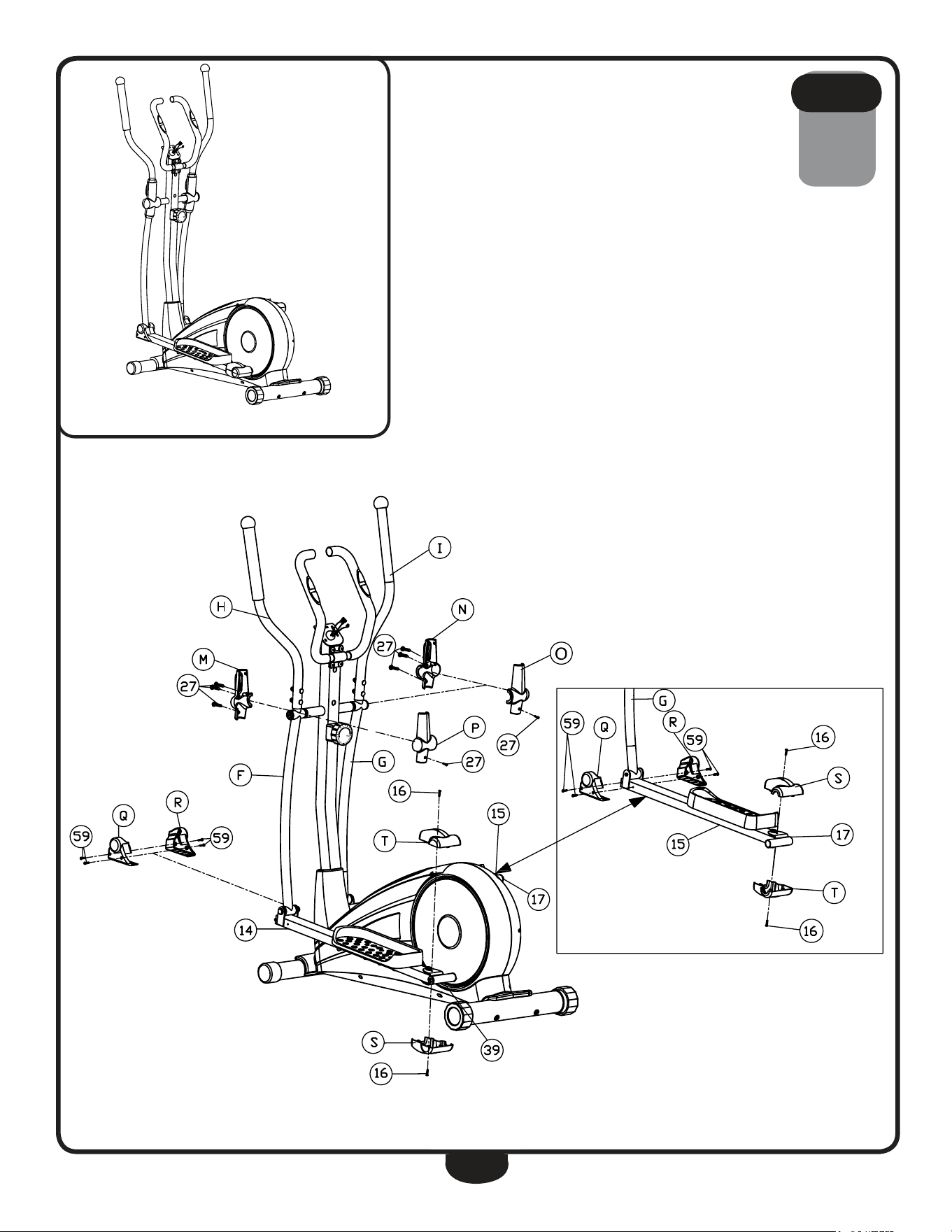
in the sequence they are presented.
noTe: Plastic needs to be pinched to release clip.
6A. Connect lower Foot Frame Shroud (s) and upper Foot Frame
Shroud (t) to left Joint Frame (39) and secure using:
two 16 (m5x10mm cross pan head screw)
6B. Connect lower Foot Frame Shroud (s) and upper Foot Frame
Shroud (t) to right Joint Frame (17) and secure using:
two 16 (m5x10mm cross pan head screw)
6C. Connect left Stride Shroud (r) and right Stride Shroud (q) to the
pivot between left Stride Bar (f) and left Foot Frame (14) and secure
using:
four 59 (m4.2x18 phillips head screw)
6d. Connect left Stride Shroud (r) and right Stride Shroud (q) to the
pivot between right Stride Bar (g) and right Foot Frame (15) and
secure using:
four 59 (m4.2x18mm phillips head screw)
6e. Connect left Front handle Shroud (m) and left rear handle Shroud
(p) to the pivot between left handle (h) and left Stride Bar (f) and
secure using:
four 27 (m3.5x10mm phillips head screw)
6F. Connect right rear handle Shroud (o) and right Front handle
Shroud (n) to the pivot between right handle (i) and right Stride Bar
(g) and secure using:
four 27 (m3.5x10mm phillips head screw)
s T e p
6
19
s T e p
6
Above shows STeP 6 assembled and completed.
** Some of the hardwares
have been preinstalled.

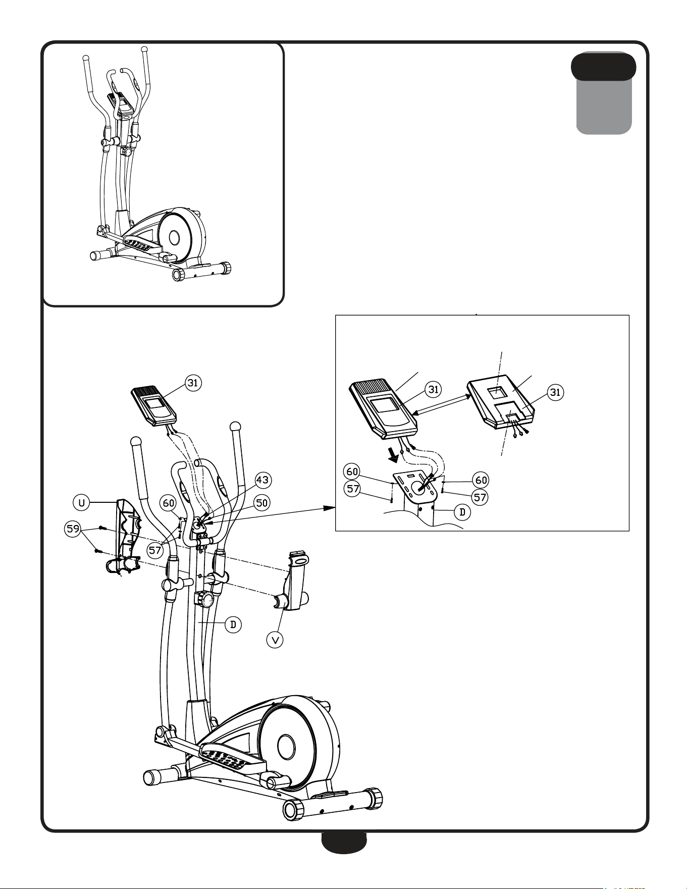
20
be careful to assemble all components
in the sequence they are presented.
7A. Slide Console (31) onto upright (d).
7B. Secure Console (31) to upright (d) using:
two 57 (m4x10mm cross pan head screw)
two 60 (m5 Washer)
7C. Connect rear upright Shroud (V) and Front upright Shroud (U) to
upright (d) and secure using:
two 59 (m4.2x18mm phillips head screw)
7d. Connect hr Cable harness (43) and upper harness (50) to
Console (31).
noTe: Carefully fit the wires back into the hole in upright (d) before
securing the console.
s T e p
7
21
s T e p
7
Above shows STeP 7 assembled and completed.
Battery Compartment
Front
Back
Insert upright here
** Some of the hardwares
have been preinstalled.
22
seTTing up Your bfcT1
PlaceMent in Your HoMe
To make exercise a desirable daily activity for you, the BFCT1 should be placed in a comfortable and
attractive setting. This cross trainer is designed to use minimal floor space and to fit nicely in your
home.
do not place or operate the BFCT1 outdoors.
do not place the BFCT1 near water or in high moisture content environment.
It is highly recommended to place a dedicated equipment mat beneath your BFCT1.
A dedicated mat provides superior stability and firmness for a proper workout.
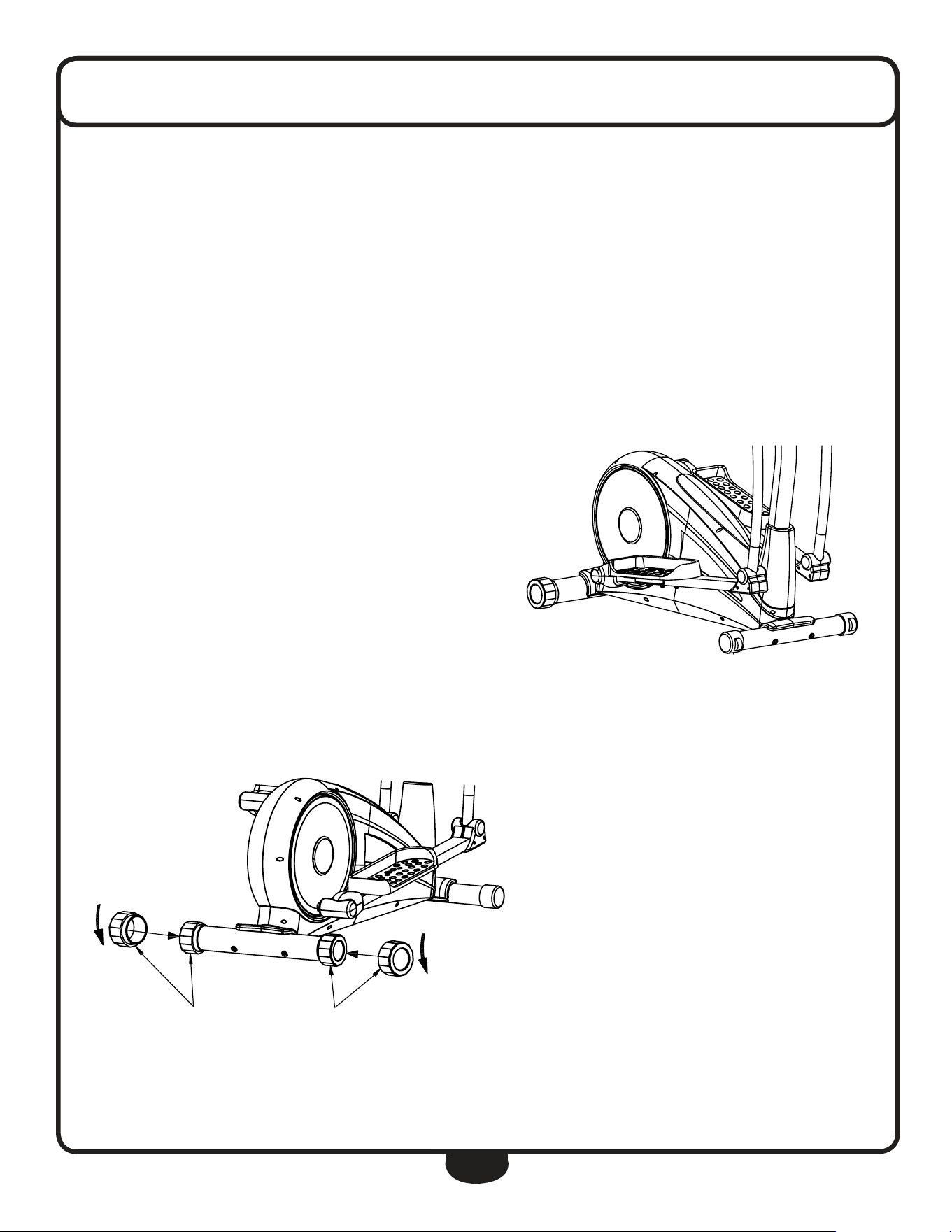
MoVing tHe Bfct1
This cross trainer is easy to move around safely.
To move the BFCT1:
1. grasp the handles.
2. Carefully pull the handles towards you
while pushing the front of the cross trainer
downward.
3. Simply roll the BFCT1 on its two wheels
to the desired location.
leVeling tHe Bfct1
The rear leg end Caps can be adjusted
to level the BFCT1:
1. rotate the rear leg end Cap
clockwise or counter-clockwise to
adjust the level of the cross trainer.
seTTing up Your bfcT1
23
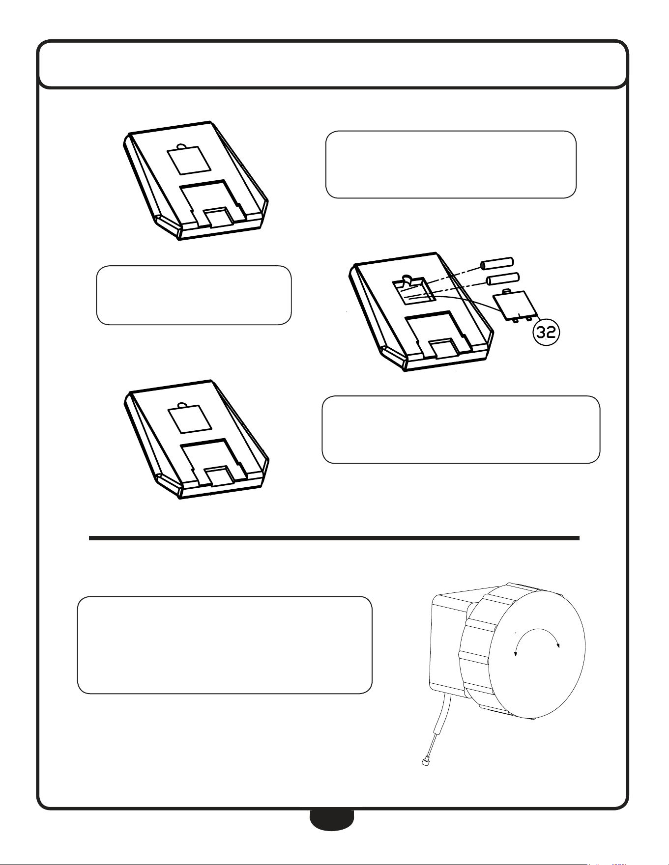
To install the Console batteries (1) ,
remove Battery Cover (32).
Insert two AA batteries into the
console. Observe polarity.
After battery installation,
reinstall the console’s Battery Cover (32).
1
2
3
4
5
6
7
8
T
e
n
s
i
o
n
C
o
n
T
r
o
l
loW HiGH
-
+
Adjust TENSION CONTROL by rotating the
TENSION CONTROL knob.
Rotate clockwise to increase tension.
Rotate counter-clockwise to decrease tension.
+
-
-
+
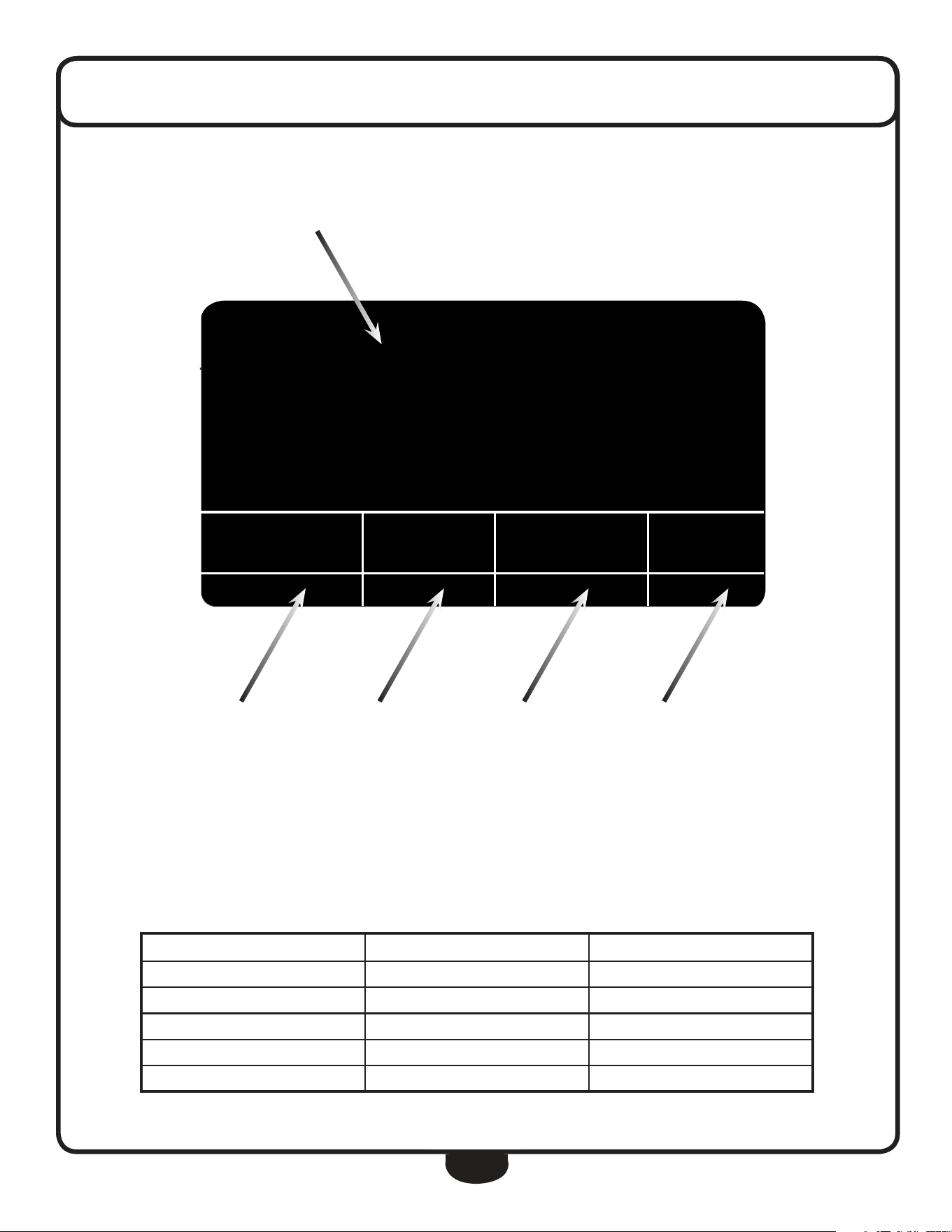
24
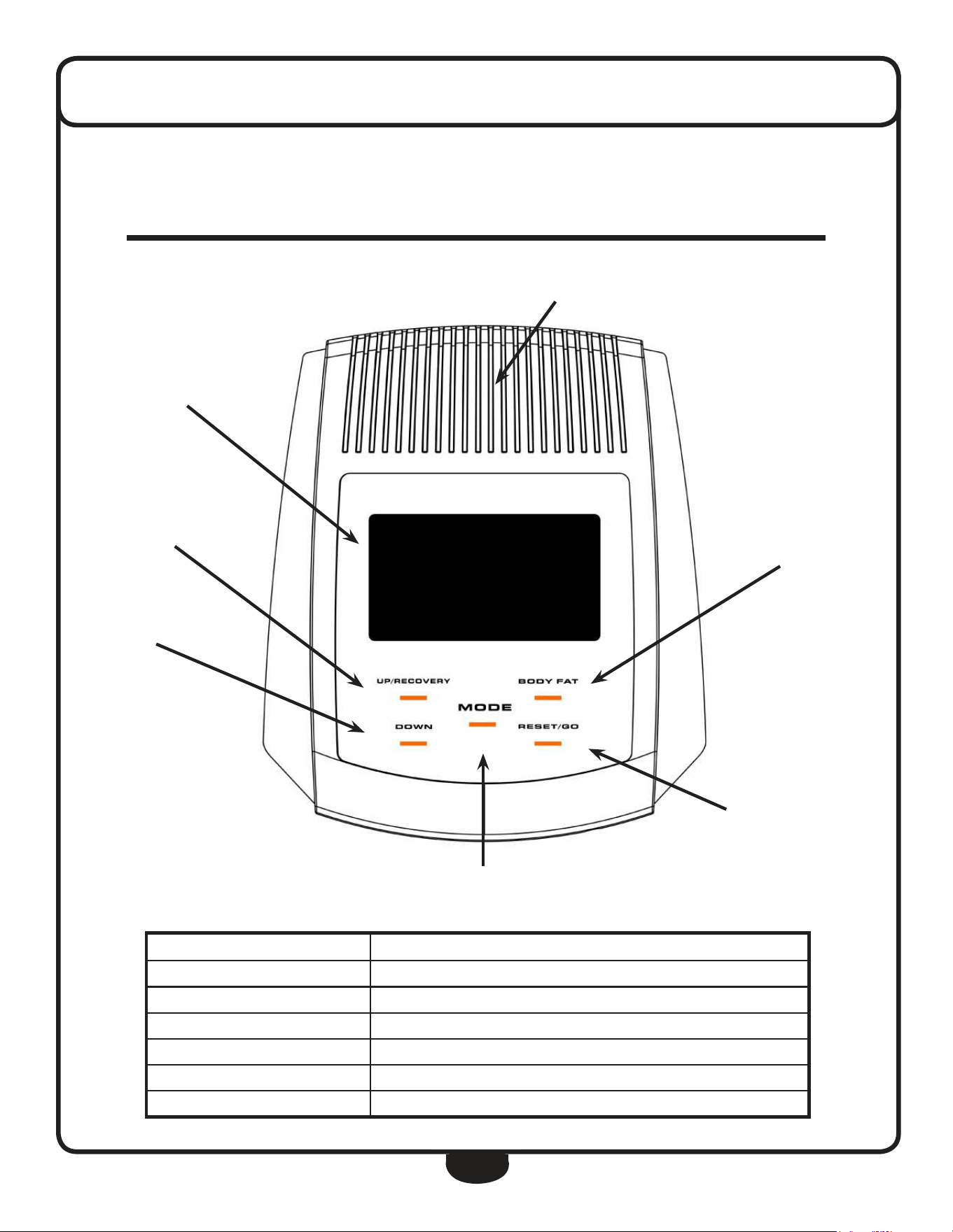
The console informs the user with valuable information about the workout and allows
the user to control workout resistance levels. Please become familiar with the console
before your first exercise session.
LCD DISPLAY
UP/RECOVERY
DOWN
BODY FAT
RESET/GO
MODE
SPEAKER
console feaTures
f e a t u r e d e s c r i p t i o n
lcD Display Console screen
MoDe Cycle through console programming
BoDYfat Calculate Body Fat percentage, BMI and BMr
reset/go reset the display/value
uP/recoVerY Increases a value (Time, Age, Distance, Calories)
DoWn decreases a value (Time, Age, Distance, Calories)
25
console displaY feaTures
f e a t u r e r a n g e s p e c i f i c a t i o n
speed 0.0 ~ 99.9 mph 0.1 Mile/hour
time 0.00 ~ 99.59 s 1 Second
calories 0 ~ 999 Calories 0.1 ~ 1 Calorie
Hand Pulse 40 ~ 240 bpm 1 Beat/Minute
Distance 0 ~ 9.99mi ~ 99.9 mi 0.01 ~ 0.1 Mile
tiMe Dis cal Pulse
♥
0:40 0.05 0.6 P
5.9
sPeeD
TIME DISTANCE CALORIES PULSE
SPEED
M
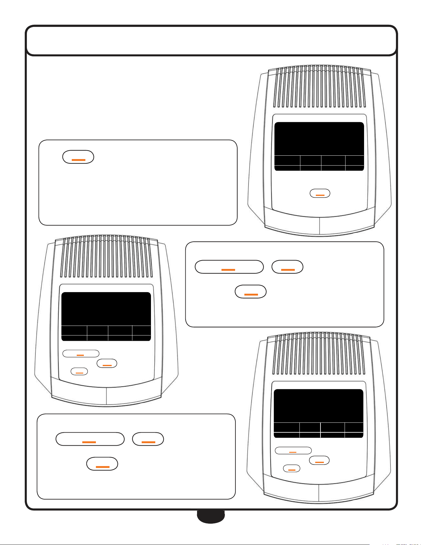
26
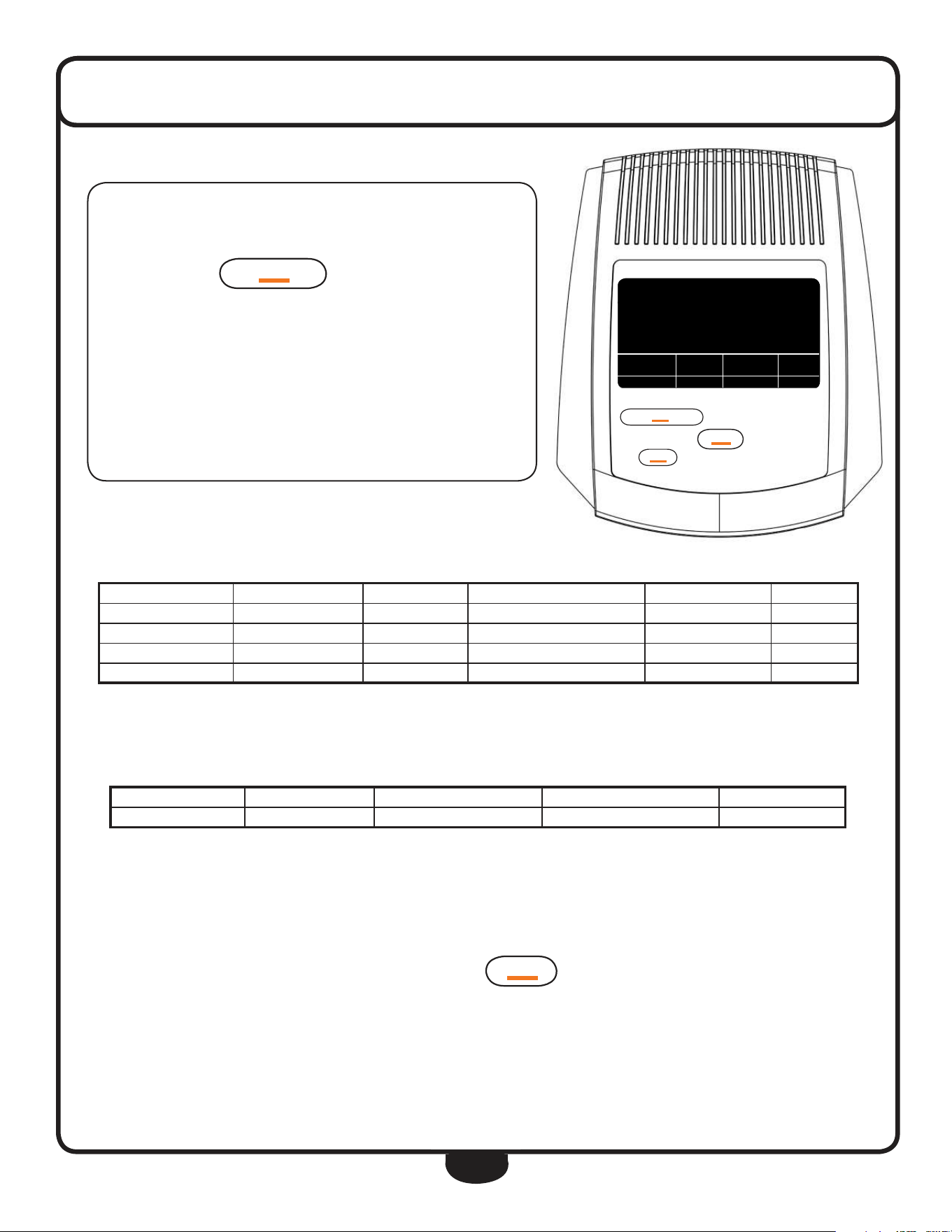
Press
M
OD
e
once to program the console.
If the console is in STAND BY mode, the display will initially reset.
After leaving STAND BY mode, the display was reset.
console operaTion
PROGRAMMING THE DISPLAY
The display is able to be programmed to establish customized workout goals.
The BFCT1 gives users the power to control their workout time, distance
travelled and total calorie loss.
As the DISTANCE window ashes, enter the pre-set DISTANCE by press-
ing
uP/re
CO
VerY
or
DO
Wn
to increase/decrease the
set value to reach your desired distance.
Again press the
M
OD
e
button to advance to the next function.
The display is set for a distance of 2.5 mi.
teMP.
76
º
f
uP/re
CO
VerY
M
OD
e
DO
Wn
reset/g
O
B
OD
Y fat
uP/re
CO
VerY
M
OD
e
DO
Wn
reset /g
O
B
OD
Y fat
tiMe Dis cal Pulse
♥
0:00 0.00 0.0 0
0.0
sPeeD
teMP.
76
º
f
uP/re
CO
VerY
M
OD
e
DO
Wn
reset/g
O
B
OD
Y fat
uP/re
CO
VerY
M
OD
e
DO
Wn
reset /g
O
B
OD
Y fat
tiMe Dis cal Pulse
♥
3:00 0.00 0.0 o
0.0
sPeeD
teMP.
76
º
f
uP/re
CO
VerY
M
OD
e
DO
Wn
reset/g
O
B
OD
Y fat
uP/re
CO
VerY
M
OD
e
DO
Wn
reset /g
O
B
OD
Y fat
tiMe Dis cal Pulse
♥
3:00 2.50 0.0 0
0.0
sPeeD
As the TIME window ashes, enter the pre-set TIME by pressing
uP/re
CO
VerY
or
DO
Wn
to increase/decrease the set
value to reach your desired time.
Again press the
M
OD
e
button to advance to the next function.
The display is set for a 3:00 minute workout.
M
M
M
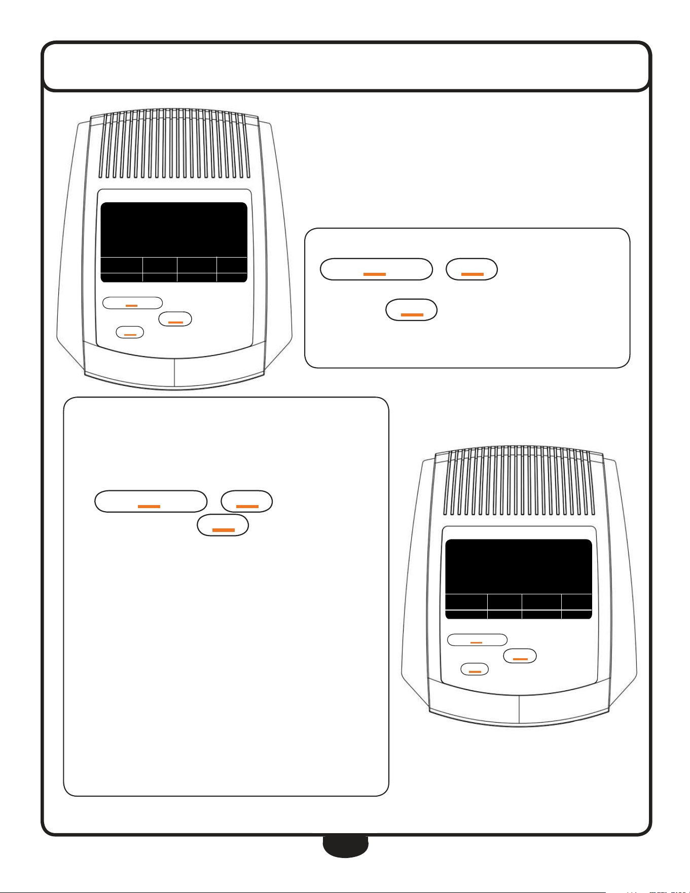
27
console operaTion
As the CALORIE window ashes, enter the pre-set CALORIES by pressing
uP/re
CO
VerY
or
DO
Wn
to increase/decrease the set
value to reach your desired calorie setting.
Again press the
M
OD
e
button to advance to the next function.
This workout will burn 45 calories.
teMP.
76
º
f
uP/re
CO
VerY
M
OD
e
DO
Wn
reset/g
O
B
OD
Y fat
uP/re
CO
VerY
M
OD
e
DO
Wn
reset /g
O
B
OD
Y fat
tiMe Dis cal Pulse
♥
3:00 2.50 45.0 0
0.0
sPeeD
The TEMPERATURE mode can be set according to specic needs. Main-
taining the correct ambient temperature during a workout will increase
the eectiveness of the exercise.
Enter the desired TEMPERATURE readout (Celsius or Fahrenheit) by press-
ing
uP/re
CO
VerY
or
DO
Wn
to change between Cel-
sius or Fahrenheit. Press the
M
OD
e
button to complete program-
ming the display.
The display is set for Fahrenheit.
Start your workout!
The programmed sections of the display will start counting down as the
exercise progresses. When one of the target goals has been achieved,
the programmed window will ash and the console will beep advising
the user of their accomplishment. After the achievement, the display
will count up and record further workout progress.
teMP.
76
º
f
uP/re
CO
VerY
M
OD
e
DO
Wn
reset/g
O
B
OD
Y fat
uP/re
CO
VerY
M
OD
e
DO
Wn
reset /g
O
B
OD
Y fat
tiMe Dis Pulse
♥
3:00 2.50 o
0.0
sPeeD
teMP.
º
f
M
M

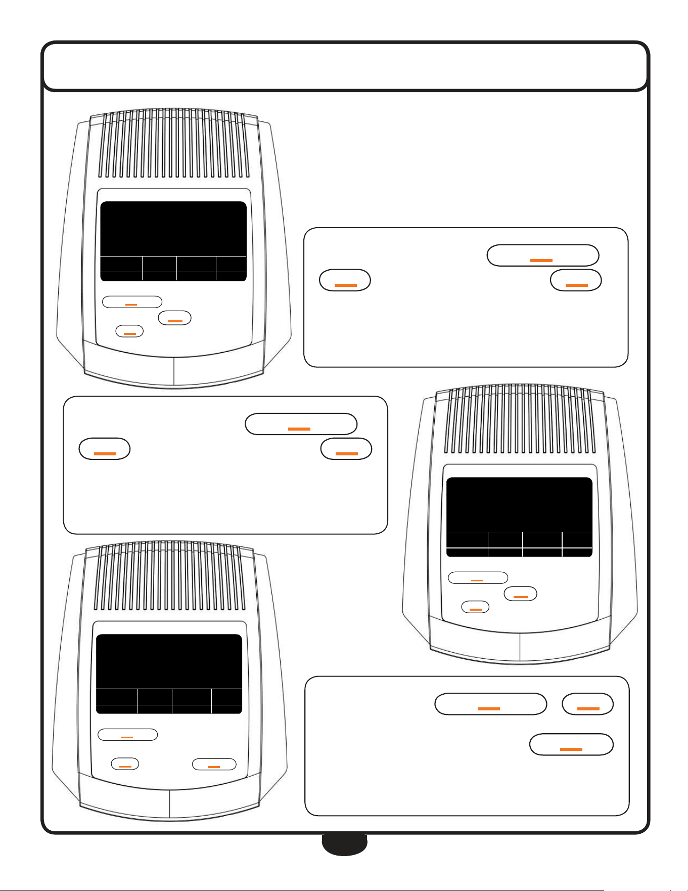
28
While not exercising, press
B
OD
Y fat
to enter the Body Fat
parameters settings.
The calculation is performed while not exercising. Speed is 0 mph.
console operaTion
BODYFAT, BMI & BMR
The BFCT1 console has the ability to measure a person’s BODYFAT, BMI and
BMR. BMI (Body Mass Index) is a statistical measurement of body weight
based on a person’s weight and height. Though it does not actually measure
the percentage of body fat, it is used to estimate a healthy body weight and
used as a diagnostic tool to identify weight problems. BMR (Basal Metabolic
Rate) determines your daily calorie needs.
Enter your WEIGHT (LB) by pressing
uP/re
CO
VerY
or
DO
Wn
to increase/decrease your set weight. Press
M
OD
e
to
advance to the next parameter setting.
Weight is set at 95 lb.
teMP.
76
º
f
uP/re
CO
VerY
M
OD
e
DO
Wn
reset/g
O
B
OD
Y fat
uP/re
CO
VerY
M
OD
e
DO
Wn
reset /g
O
B
OD
Y fat
tiMe Dis cal Pulse
♥
0:00 0.00 0.0 0
0.0
sPeeD
teMP.
76
º
f
uP/re
CO
VerY
M
OD
e
DO
Wn
reset/g
O
B
OD
Y fat
uP/re
CO
VerY
M
OD
e
DO
Wn
reset /g
O
B
OD
Y fat
teMP.
3
5 5
no.
lb
76
º
f
teMP.
76
º
f
uP/re
CO
VerY
M
OD
e
DO
Wn
reset/g
O
B
OD
Y fat
uP/re
CO
VerY
M
OD
e
DO
Wn
reset /g
O
B
OD
Y fat
teMP.
3
9 5
no.
lb
76
º
f
Multiple users can examine their BODYFAT. Enter the USER ID number
from 1 to 8 by pressing
uP/re
CO
VerY
or
DO
Wn
to
increase/decrease the USER ID. Press
M
OD
e
to advance to next
parameter setting.
The display will calculate BODYFAT for user number 3.
M
29
console operaTion
Enter your HEIGHT (inch) by pressing
uP/re
CO
VerY
or
DO
Wn
to increase/decrease your set height. Press
M
OD
e
to
advance to the next parameter setting.
The height of USER 3 is set at 70”.
teMP.
76
º
f
uP/re
CO
VerY
M
OD
e
DO
Wn
reset/g
O
B
OD
Y fat
uP/re
CO
VerY
M
OD
e
DO
Wn
reset /g
O
B
OD
Y fat
teMP.
3
70
no.
in
76
º
f
teMP.
76
º
f
uP/re
CO
VerY
M
OD
e
DO
Wn
reset/g
O
B
OD
Y fat
uP/re
CO
VerY
M
OD
e
DO
Wn
reset /g
O
B
OD
Y fat
teMP.
3
29
no.
Year
76
º
f
teMP.
76
º
f
uP/re
CO
VerY
M
OD
e
DO
Wn
reset/g
O
B
OD
Y fat
uP/re
CO
VerY
M
OD
e
DO
Wn
reset /g
O
B
OD
Y fat
teMP.
3
70
no.
in
76
º
f
Enter your AGE (YEAR) by pressing
uP/re
CO
VerY
or
DO
Wn
to increase/decrease your age setting. Press
M
OD
e
to proceed to next parameter setting.
USER 3 is 29 years old.
Enter your SEX by pressing
uP/re
CO
VerY
or
DO
Wn
to select between male and female.
After having entered the parameters, press the
reset/g
O
button then hold onto the Heart Rate Contacts.
USER 3 is female.
30
After 6 seconds, the console will display the executed calculation on the
display. The display will show BODYFAT, BMI and BMR. To exit the ap-
plication, press the
B
OD
Y fat
button.
USER 3 has 21.8% BODYFAT, a BMI of 22 and a BMR of 1640 calories.
NOTE: The display will exit the BODYFAT test automatically if no console
operation has been detected for a period of 10 seconds and will display
the Er.1 error code.
console operaTion
DO
Wn
reset /g
O
teMP.
76
º
f
uP/re
CO
VerY
M
OD
e
DO
Wn
reset/g
O
B
OD
Y fat
uP/re
CO
VerY
M
OD
e
DO
Wn
reset /g
O
B
OD
Y fat
BMi BMr teMP.
3
21.8
no.
%
22 1.64 76
º
f
G e n d e r / A g e U n d e r w e i g h t H e a l t h y S l i g h t l y O v e r w e i g h t O v e r w e i g h t O b e s e
Male ≤ 30 years <14% 14% ~ 20% 20.1% ~ 25% 25.1% ~ 35% > 35%
Male > 30 years <17% 17% ~ 23% 23.1% ~ 28% 28.1% ~ 38% > 38%
Female ≤ 30 years <17% 17% ~ 24% 24.1% ~ 30% 30.1% ~ 40% > 40%
Female > 30 years <20% 20% ~ 27% 27.1% ~ 33% 33.1% ~ 43% > 43%
BODYFAT PARAMETERS
The chart below is used to reference your BODYFAT results. Results are for therapeutic purposes only.
BMI INDEX
The chart below is used to reference your BMI (Body Mass Index) results. Results are for therapeutic purposes only.
SLEEP MODE
The BFCT1 will enter SLEEP MODE mode when left un-operational for eight minutes after a workout. While SLEEP MODE mode is ac-
tive, the console will display the current ambient temperature. Press
M
OD
e
once to reset the display and start your workout.
All memory is cleared during SLEEP MODE except for BODYFAT parameters and Temperature.
U n d e r w e i g h t H e a l t h y S l i g h t l y O v e r w e i g h t O v e r w e i g h t O b e s e
≤ 18 18.5 ~ 24.9 25 ~ 26.9 27 ~ 29.9 ≥ 30
31
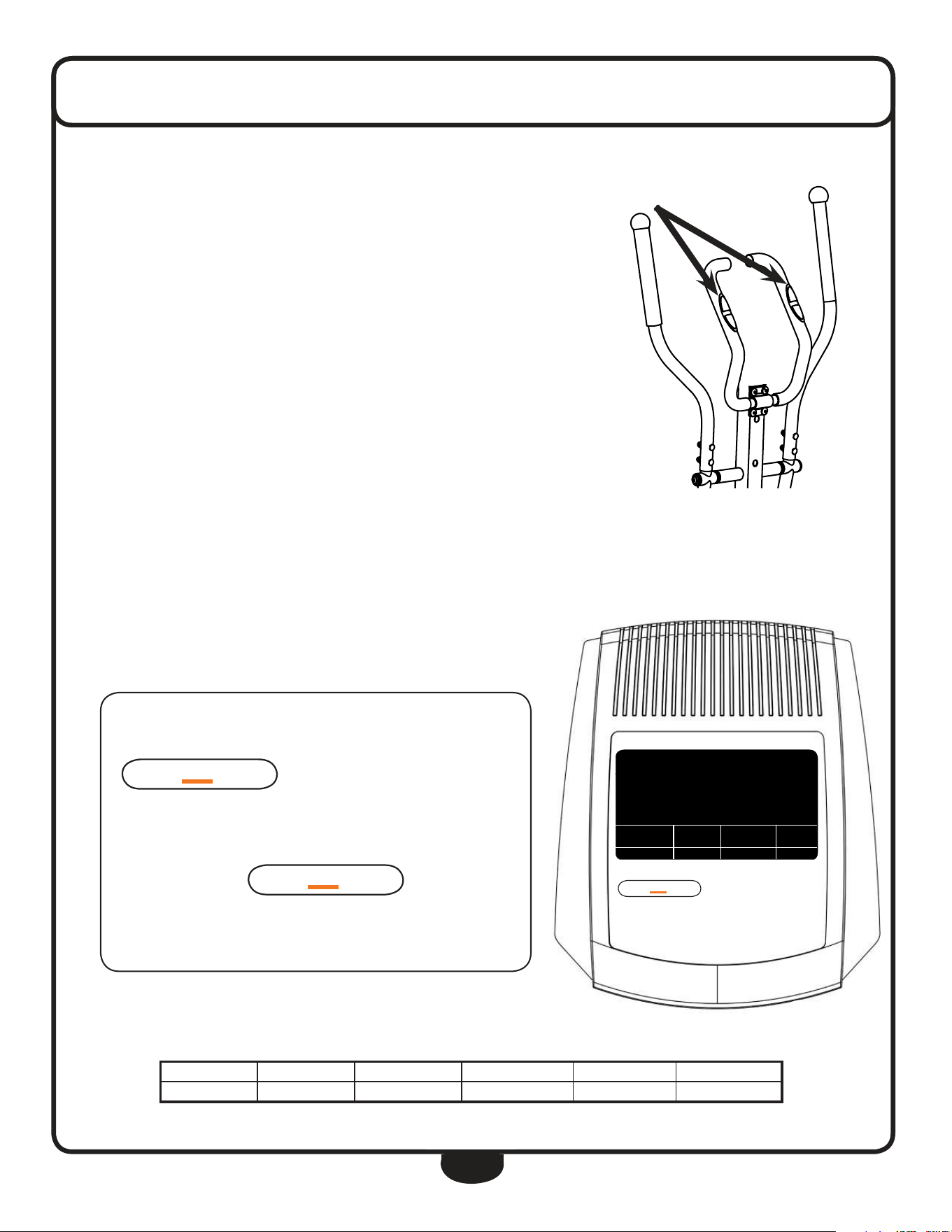
console operaTion
Pulse rate
Your BFCT1 comes equipped with Heart Rate Contacts. The Heart Rate Contacts send
your heart rate information to the console for processing. To measure Heart Rate, your
hands need to rmly grasp the entire area of the Heart Rate Contact Sensors on both
sides of the handlebar. There is no need to hold onto the contacts very tightly although
holding onto the contacts loosely may produce a false readout.
Before measuring your pulse rate, make sure the PULSE window shows ‘P’ instead of ‘0’.
The readout may show ‘0’ after a brief period of pulse reading inactivity. Press any but-
ton to change ‘0’ into “P” to activate the pulse readout. Place both of your palms on the
Heart Rate Contact Pads and the monitor will show your current heart rate in beats per
minute (BPM) after a 3~4 second calculation time.
During the Heart Rate reading, because of the contact jamming phenomenon, the mea-
sured Heart Rate value may be higher than your actual pulse rate during the rst 2~3
seconds, then will stabilize to a normal level.
teMP.
76
º
f
uP/re
CO
VerY
M
OD
e
DO
Wn
reset/g
O
B
OD
Y fat
uP/re
CO
VerY
M
OD
e
DO
Wn
reset /g
O
B
OD
Y fat
tiMe Pulse
♥
0:00 o
f 2
PULSE RECOVERY
PULSE RECOVERY is an excellent guide for many types of training regimes that
use recovery heart rate as a progress guide and to spot problems such as over-
heating or dehydration.
First, test your pulse as mentioned in the PULSE RATE sec-
tion. Then, while not exercising (SPEED is 0 mph), press
uP/re
CO
VerY
to enter the PULSE RECOVERY function.
The display will show a 1 minute count-down as well as your current
pulse rate. Hold on to the Heart Rate Contacts until the display counts
down to zero. The console will now display your pulse recovery level
from F1 to F6. Press
uP/re
CO
VerY
again to exit the
PULSE RECOVERY function.
The Pulse Recovery is at the F2 level.
F a s t e s t F a s t Q u i c k M o d e r a t e S l o w S l o w e s t
F1 F2 F3 F4 F5 F6
The chart below is used to reference your PULSE RECOVERY level. Results are for therapeutic purposes only.

32
exercise Tips and guidelines
stretcH
Stretching prior to exercising will improve flexibility and reduce chances of exercise related injury.
ease into each of these stretches with a slow gentle motion. hold your stretched position for a count
of ten. do not bounce. repeating the stretching exercises again, after the cool down, will help to
loosen and relax your muscles to prevent soreness after your workout.
WarM uP
A few minutes of a work out should be devoted to warming up. This warm up time will limber your
muscles and prepare them for a more strenuous exercise. Warm up on the BFCT1 by exercising at
slow speeds.
cool DoWn
never stop exercising suddenly. It is a good idea to end a workout slowly since this will allow your
heart to readjust to the decreased demand.
HoW often?
It is most often recommended that you exercise a few times a week to maintain cardiovascular fit-
ness. If you have other goals such as weight or fat loss, you will achieve your goal faster with more
frequent exercise. remember that your ultimate goal should be to make exercise a lifetime habit.
Many people are successful staying with a fitness program if they set aside a specific time of the day
to exercise. regular exercise is a key to a healthy life style
HoW long?
For a useful workout, always start slowly, especially if you have been sedentary during the past year.
Your body will need time to adjust to the new activity. As your body adjusts, gradually increase your
workout time per session.
Always consult your physician before beginning any exercise program. For your health and
safety, do not over exert yourself. remember to stretch and warm up before each exercise
program.

33
exercise Tips and guidelines
HoW HarD?
how hard you work out is determined by your goal. regardless of your fitness goals, always begin an
exercise program at low intensity. Aerobic exercise does not have to be painful to be beneficial!
There are two ways to measure your exercise intensity. The first is by evaluating your perceived exer-
tion level and the second is by monitoring your heart rate.
during exercise, if you cannot maintain a conversation without gasping, you are working too hard.
A good rule of thumb is to work to the point of exhilaration, not exhaustion. If you cannot catch your
breath, it is time to slow down. Always be aware of other warning signs to overexertion.
To monitor your heart rate you can use a pulse monitor or take your pulse with your fingers. Pulse
monitors are convenient tools for monitoring your heart rate. however, these values are for reference
only. You should always listen to your body first.
You can measure your pulse with your fingers by placing your first two fingers lightly over the blood
vessel (carotid artery) on your neck located next to your Adam’s apple. Count your pulse for ten
seconds and multiply by six. This figure is your heart rate in beats per minute (bpm). Compare this
number to the Target heart rate zone for your age group.
target Heart rate
The most common method for calculating your target
heart rate is to find your maximum heart rate.
The standard formula for this is:
220 - your age = maximum heart rate.
You do noT want to workout at your maximum heart rate.
You want to workout in your target heart rate zone.
Your target heart rate zone is a percentage of your
maximum heart rate. The American heart Association
recommends working out at a target heart rate zone
of between 60% - 75% of your maximum heart rate.
If you are just beginning an exercise program,
exercise near or below the lower limit of your target zone.
lower target Zone limit = maximum heart rate x 0.60
uPPer target Zone limit = maximum heart rate x 0.75
If you experience chest pains, nausea, dizziness or shortness of breath, stop exercising im-
mediately and consult your physician before continuing any workouts!
Age Target Zone
20 120 ~ 150
25 117 ~ 146
30 114 ~ 142
35 111 ~ 138
40 108 ~ 135
45 105 ~ 131
50 102 ~ 127
55 99 ~ 123
60 96 ~ 120
65 93 ~ 116
70 90 ~ 113
target Heart rate

34
TroubleshooTing
P R O B L E M T R O U B L E S H O O T I N G T I P S O L U T I O N
Console will not turn on
Console needs a HARD reset
Batteries are low or dead
Reverse polarity
Damaged console
Remove then reinstall batteries into the console.
Replace with fresh batteries.
Insert batteries using correct polarity.
Replace console.
Crank Arms or Handles are loose
Loose hardware Using the provided assembly tools, go over the BFCT1 to make sure
all assembly hardware is tight.
No resistance
Tension Knob malfunction
Magnetic brake is loose
Call for service.
Call for service.
The resistance levels seem to be either too hard or too
easy
Magnetic brake has shifted Call for service.
Console button(s) do not respond to touch
Console Overlay Button(s) may have been damaged from liquids penetrating con-
sole overlay or excessive amount of cleaning solution was used.
Too much force was used operating the console buttons.
Replace console.
No Heart Rate readout on console
Heart Rate harness Remove the console and verify that the Heart Rate harness is se-
cure.
Heart Rate readout is erratic
Heart Rate contact pressure
Contact obstruction
Environmental interference
Gripping the Heart Rate contacts too tight may cause calculation
readout errors.
Try to maintain moderate pressure when holding onto the Heart
Rate contacts.
Remove all jewelry when using the BFCT1.
Make sure hands are not completely dry.
An exercise environment with large motors, computers, uores-
cent lighting and high power lines may cause erratic Heart Rate
readout.
Unit is unstable or rocks while in use
Levelers Make sure the unit is on a solid and level surface.
Adjust the Rear Leg End Caps to level the unit.
Speed is not calculated on the console
Console Harness
Speed Sensor
Magnet
Remove the console and verify that all connections are secure and
not damaged or pinched.
The Speed Sensor may have become dislodged or damaged.
Call for service.
The Magnet may have become dislodged or damaged.
Call for service.
The BFCT1 squeaks or makes a chirping sound
Levelers
Assembly hardware
Make sure the unit is on a solid and level surface.
Loosen all assembly hardware, grease the bolt threads then tighten
hardware.

35
servicing The bfcT1
OBTAINING SERVICE
Please use this Owner’s Manual to make sure that all parts have been included in your shipment.
When ordering parts, you must use the part number and description from this Owner’s Manual.
Use only Best Fitness replacement parts when servicing this machine. Failure to do so will void
your warranty and could result in personal injury.
For information about product operation or service, go to www.besttness.com or contact an au-
thorized Best Fitness dealer or a Best Fitness factory-authorized service company or contact Best
Fitness customer service at one of the following:
Retain this Owner’s Manual for future reference.
Toll Free: 1-800-556-3113
Phone: 1-708-427-3555
Fax: 1-708-427-3556
Hours: M-F 8:30-5:00 CST
E-Mail: service@bodysolid.com
Or write to:
BEST FITNESS
Service Department
1900 S. Des Plaines Ave.
Forest Park, IL 60130 USA
www.BestFitness.com
36
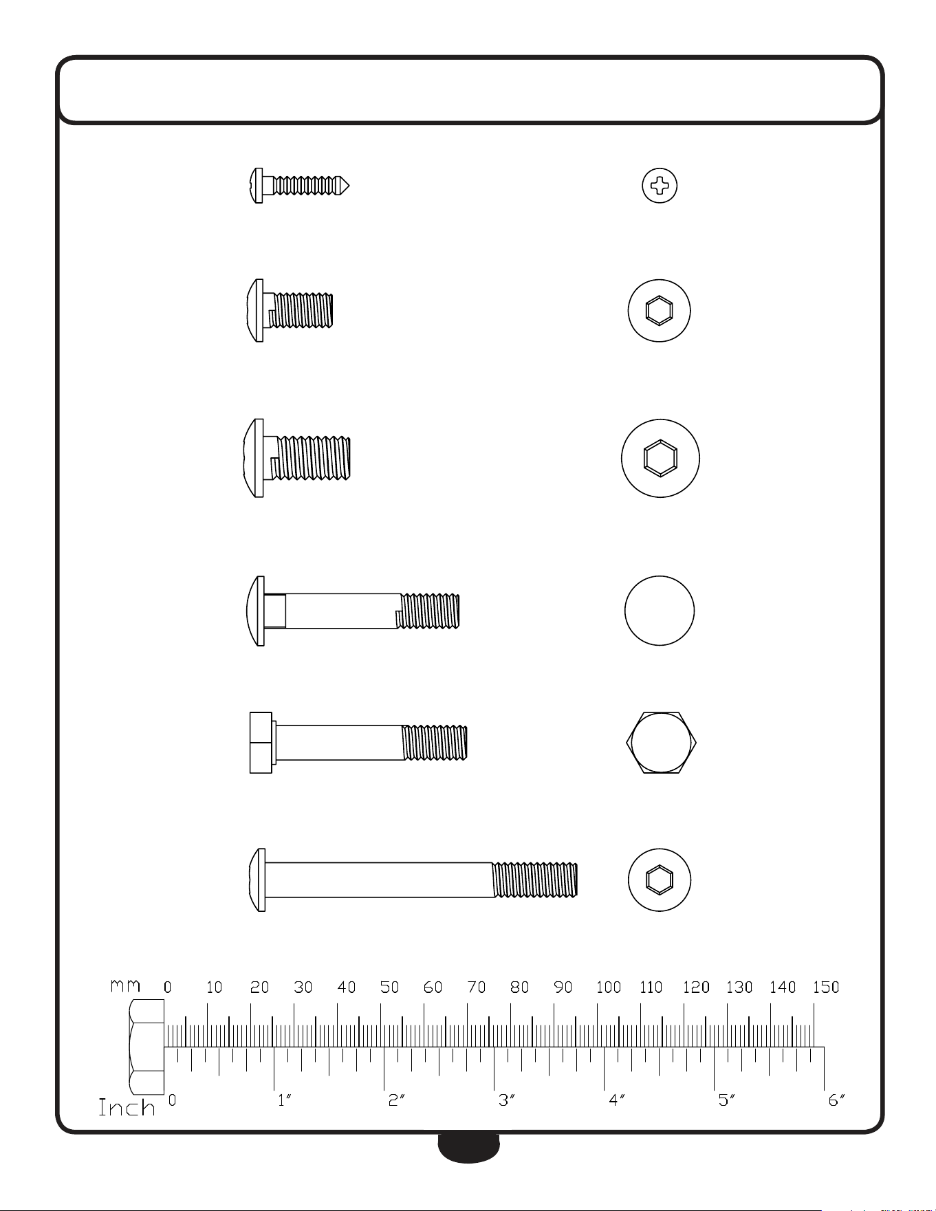
hardWare
(actual size shown)
Part# 59 ST4.2x18 Phillips Head Screw Qty. 33
Part# 45 M8x16 Round Allen Head Bolt Qty. 8
Part# 10 M10x20 Round Allen Head Bolt Qty. 4
Part# 36 M8x45 Carriage Bolt Qty. 4
Part# 37 M8x45 Hex Head Bolt (Partial Thread) Qty. 6
Part# 21 M8x72 Round Allen Head Bolt Qty. 2
37
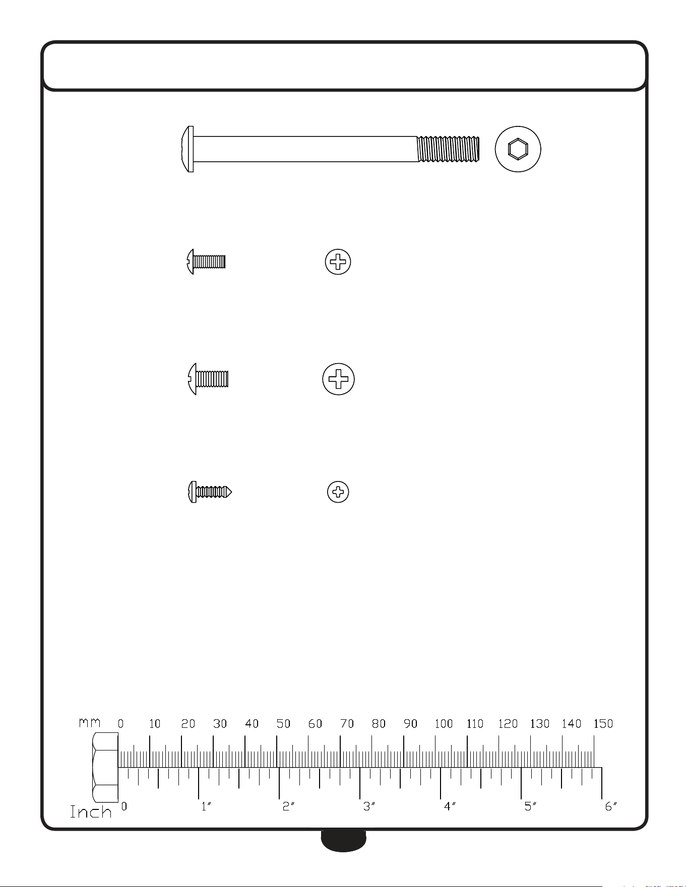
hardWare
(actual size shown)
Part# 4 M8x90 Round Allen Head Bolt Qty. 2
Part# 57 M4x10 Cross Pan Head Screw Qty. 2
Part# 16 M5x10 Cross Pan Head Screw Qty. 4
Part# 27 ST3.5x10 Phillips Head Screw Qty. 8
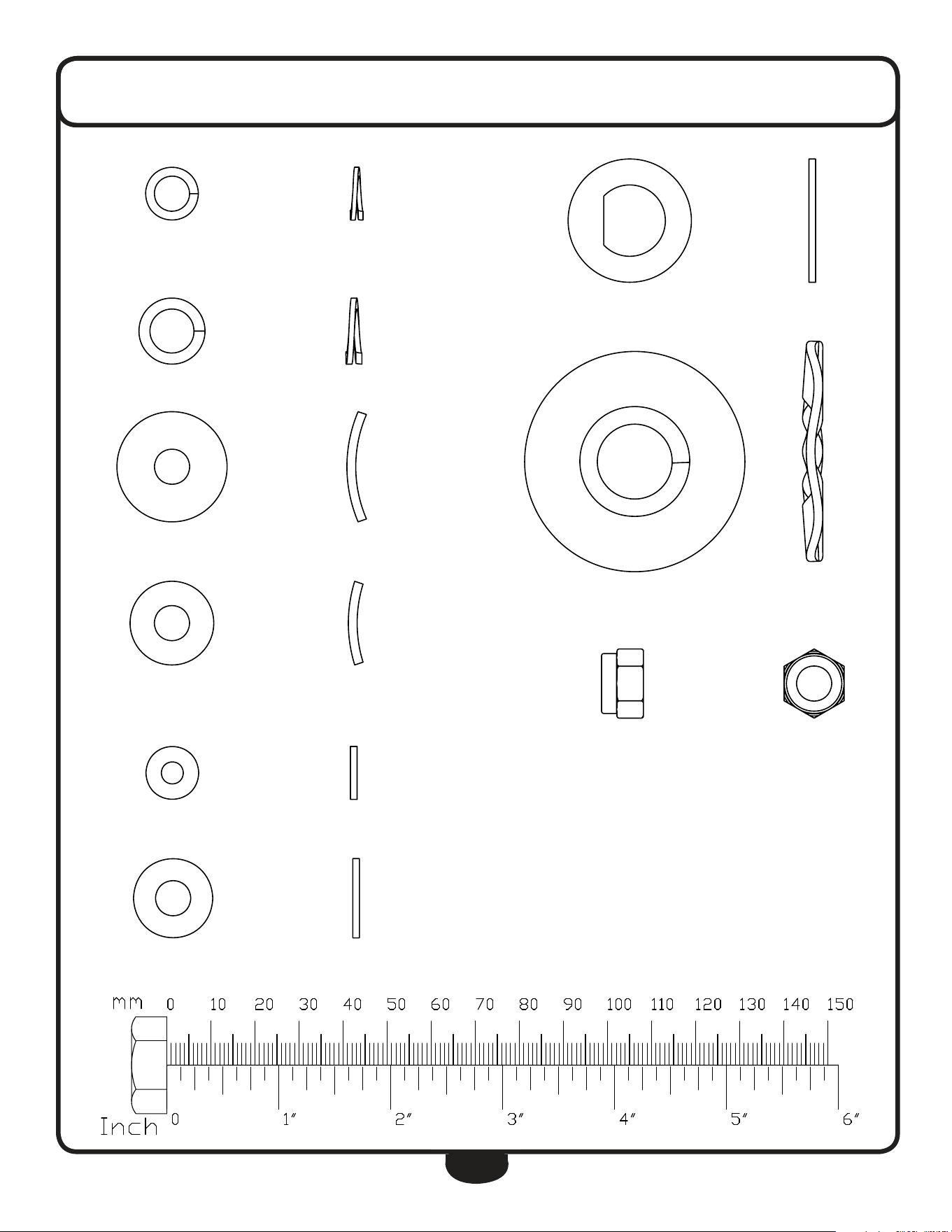
38
Part# 44 M8 Spring Washer Qty. 8
Part# 11 M10 Spring Washer Qty. 4
Part# 58 M8 Arc Washer Qty. 2
Part# 20 M8 Arc Washer Qty. 6
Part# 60 M5 Washer Qty. 2
Part# 12 M8 Washer Qty. 10
hardWare
(actual size shown)
Part# 9 M16.2 D-Washer Qty. 4
Part# 35 M17 Wave Washer Qty. 4
Part# 13 M8 Nylon Nut Qty. 10

39
assemblY hardWare lisT (sTeps 1-7)
part# qty dEscription
A 1 Main Frame
B 1 rear leg
C 1 Front leg
d 1 upright
e 1 Shroud
F 1 left Stride Bar
g 1 right Stride Bar
h 1 left handle
I 1 right handle
u 1 Front upright Shroud
V 1 rear upright Shroud
part# qty dEscription
4 2 round Allen head Bolt M8X90mm
5 2 Washer M10 (20od x 2t)
6 2 nylon lock nut M10
9 4 d-Washer 16.2Id x 28od x 14t x B5
10 4 round Allen head Bolt M10X20mm
11 4 Spring Washer M10
12 10 Washer M8 (16od x 1.5t)
13 10 nylon nut M8
14 1 left Foot Frame
15 1 right Foot Frame
16 4 Cross Pan head Screw M5X10mm
18 2 hex head Bolt Ø12x68xM10x12
20 6 Arc Washer M8 (19od x 1.5t x r30)
21 2 round Allen head Bolt M8X72mm
27 8 Phillips head Screw M3.5X10mm
31 1 Console
35 4 Wave Washer M17 (23od x 0.3t)
36 4 Carriage Bolt M8X45mm
37 6 hex head Bolt M8X45mm
43 1 hr Cable harness/hr Contact
44 8 Spring Washer M8
45 8 round Allen head Bolt M8X16mm
48 1 Tension Controller
50 1 upper harness
52 1 lower Tension Cable
53 1 lower harness
55 1 left Crank
56 1 right Crank
57 2 Cross Pan head Screw M4X10mm
58 2 Arc Washer M8 (25od x 2t x r39)
59 10 Phillips head Screw M4.2X18mm
60 2 Washer M5 (12od)
61 1 upright Axis
62 2 Washer M12 (24od x 1.5t)

40
compleTe hardWare lisT
part# qty dEscription
A 1 Main Frame
B 1 rear leg
C 1 Front leg
d 1 upright
e 1 Shroud
F 1 left Stride Bar
g 1 right Stride Bar
h 1 left handle
I 1 right handle
J 1 left Foot Plate
K 1 right Foot Plate
l 1 handle Bar
M 1 left Front handle Shroud
n 1 right Front handle Shroud
o 1 right rear handle Shroud
P 1 left rear handle Shroud
Q 1 right Stride Shroud
r 1 left Stride Shroud
S 2 lower Foot Frame Shroud
T 2 upper Foot Frame Shroud
u 1 Front upright Shroud
V 1 rear upright Shroud
W 1 Console logo
X 1 BF Shroud Badge
Y 2 drive Wheel logo
Z 1 BFCT1 rear Badge
part numbers are required when ordering parts.

41
compleTe hardWare lisT
part# qty dEscription
1 2 Starter Batteries (Type AA) Non-Warranty Item
2 2 rear leg end Cap
4 2 round Allen head Bolt M8x90
5 7 Washer M10 (20od x 2t)
6 5 nylon nut M10
7 4 Plastic Bushing 16Id x 28od x 16t
8 4 Bushing 10Id x 18 odx 11t
9 4 d-Washer 16.2Id x 28od x 14t x B5
10 4 round Allen head Bolt M10x20
11 4 Spring Washer M10
12 10 Washer M8 (16od x 1.5t)
13 10 nylon nut M8
14 1 left Foot Frame
15 1 right Foot Frame
16 4 Cross Pan head Screw M5x10
17 1 right Joint Frame
18 2 hex head Bolt Ø12x68xM10x12
19 4 Bushing 12Id x 32od x 15t
20 6 Arc Washer M8 (19od x 1.5t x r30)
21 2 round Allen head Bolt M8x72
22 2 Front leg end Cap
25 6 Bushing 16Id x 31od x23t
27 8 Phillips head Screw ST3.5 x 10
29 2 Foam grip upper handle
30 2 round end Cap upper handle
31 1 Console
32 1 Console Battery Cover
33 1 Cross head Pan Screw M5x55
34 1 Arc Washer M5
35 4 Wave Washer M17 (23od x 0.3t)
36 4 Carriage Bolt M8x45
37 6 hex head Bolt M8x45
38 2 hex head Bolt M10x55
39 1 left Joint Frame
40 2 round end Cap
41 2 handle Bar Foam
43 2 hr Cable harness/hr Contact
44 8 Spring Washer M8
45 8 round Allen head Bolt M8x16
48 1 Tension Controller
50 1 upper harness
51 2 hex head Bolt M5
52 1 lower Tension Cable
53 1 lower harness
54 1 left Shroud
part numbers are required when ordering parts.

42
compleTe hardWare lisT
part# qty dEscription
55 1 left Crank
56 1 right Crank
57 2 Cross Pan head Screw M4x10
58 2 Arc Washer M8 (25od x 2t x r39)
59 33 Phillips head Screw ST4.2x18
60 2 Washer M5 (12od)
61 1 upright Axis
62 2 Washer M12 (24od x 1.5t)
63 1 right Shroud
64 2 Shroud Cover
65 2 drive Wheel
66 2 Shaft Spring ring 12Id
67 6 Brake Magnet
68 1 Brake Magnet Frame
69 1 Tension Spring
70 1 Shaft M6 x 20 x f12 x 59.5
71 2 hex head Bolt M6x15
72 6 Spring Washer M6 (10.3od)
73 2 Washer M6 (12od x 1.5t)
74 2 Shaft Spring Washer M20
75 2 Bearing f20 x f37 x 9t (6904Z)
76 4 Allen head Bolt M6x15
77 1 Plastic Flywheel
78 1 Belt
79 1 Plastic Flywheel Shaft
80 4 nylon nut M6
81 1 Cock Wheel
82 1 hex head Bolt M5x60
83 2 hex head Bolt M6
84 1 Bushing 10Id x 18od x 6t
85 1 Allen head Bolt M10x40
86 1 Magnet Sensor
87 2 Phillips head Screw ST3x10
88 2 hexagon Bolt M10x1
89 2 Chain Adjuster Bolt M6x50
90 2 Chain Adjuster u Washer 31 x 11 x 8mm
91 8 Washer M5 (12od x 1.5t)
92 1 Flywheel Shaft
93 2 Tapered nut M10x1
94 1 Flywheel
95 2 Bushing M10x3
96 2 Flange nut M10x1.25
97 1 hr Magnet
98 1 nut Cover
99 1 Plastic Component

43
noTes
44
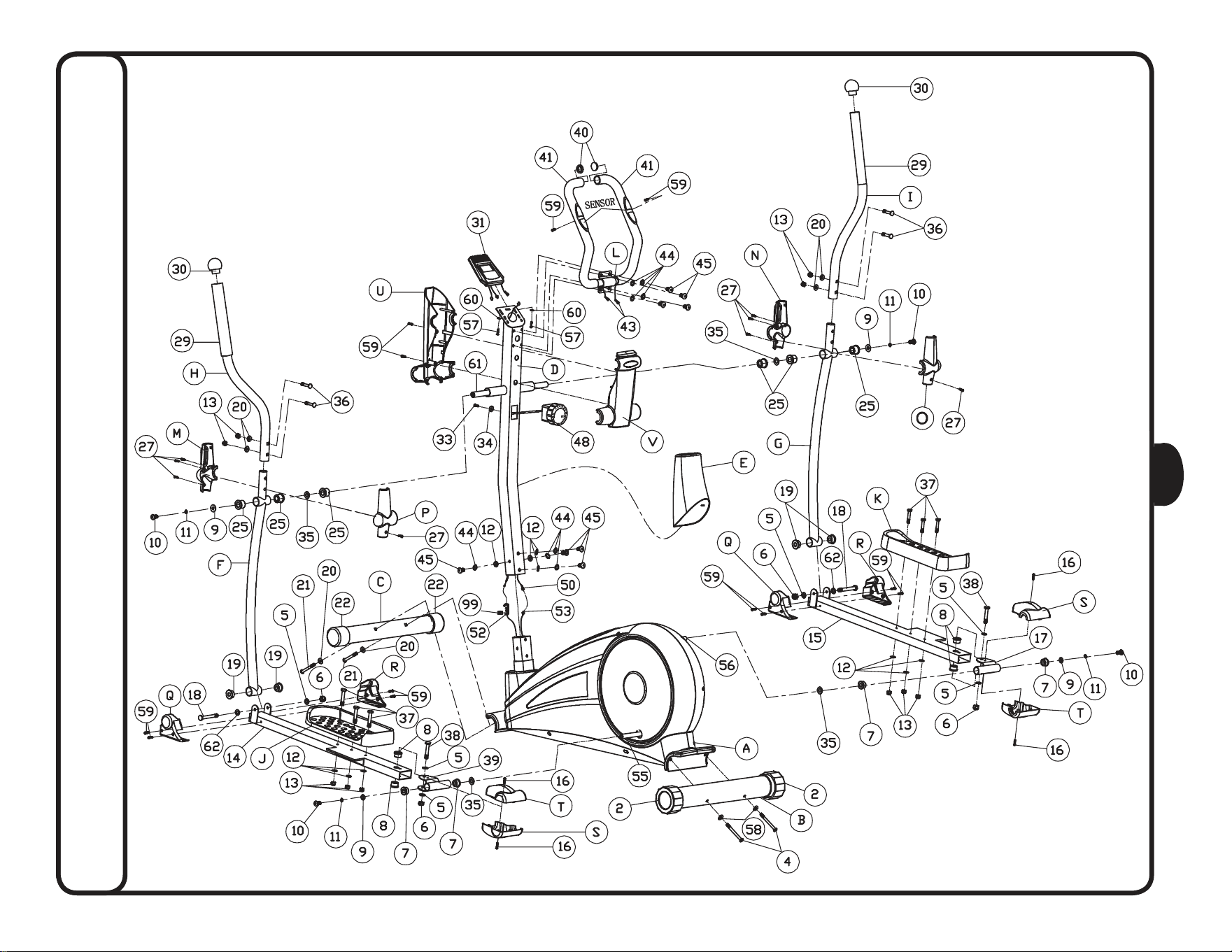
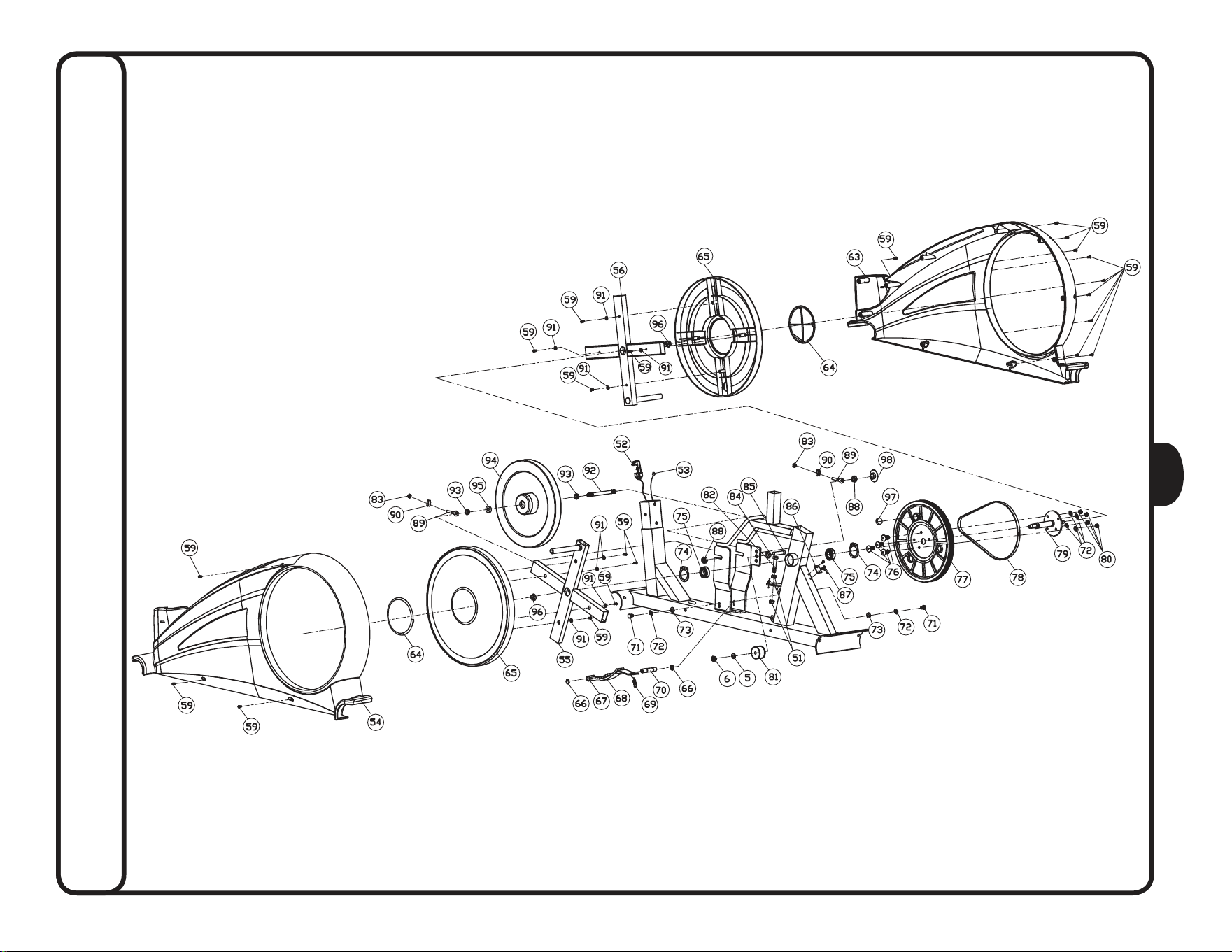
exploded vieW diagram
45
exploded vieW diagram
c
Copyright 2010. Body-Solid. All rights reserved. Body-Solid reserves the right to change design and specications when we feel it will improve the product.
Body-Solid machines maintain several patented and patent pending features and designs. All rights reserved on all design patents and utility patents.
www.BestFitness.com
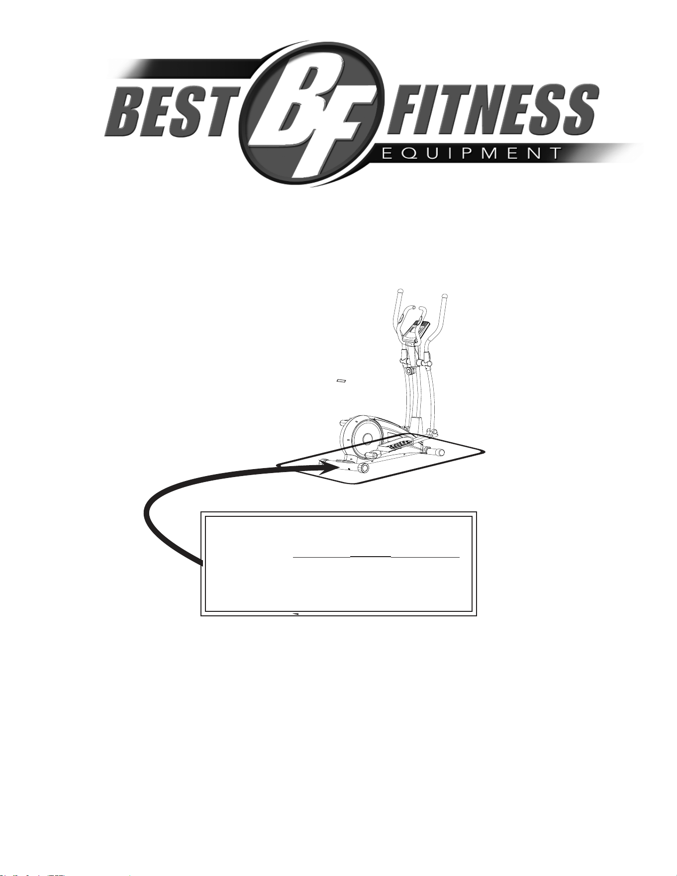
Serial Number is Located on the Frame
Model Name
:
BFCT1
Purchase Date
: _______________________________
Serial Number
: 005068-________________________
bfcT1
1900 S. des Plaines Ave.
Forest Park, Il 60130
1 (800) 556-3113
hours: M-F 8:30 - 5:00 CST
