E5000
Endurance
®
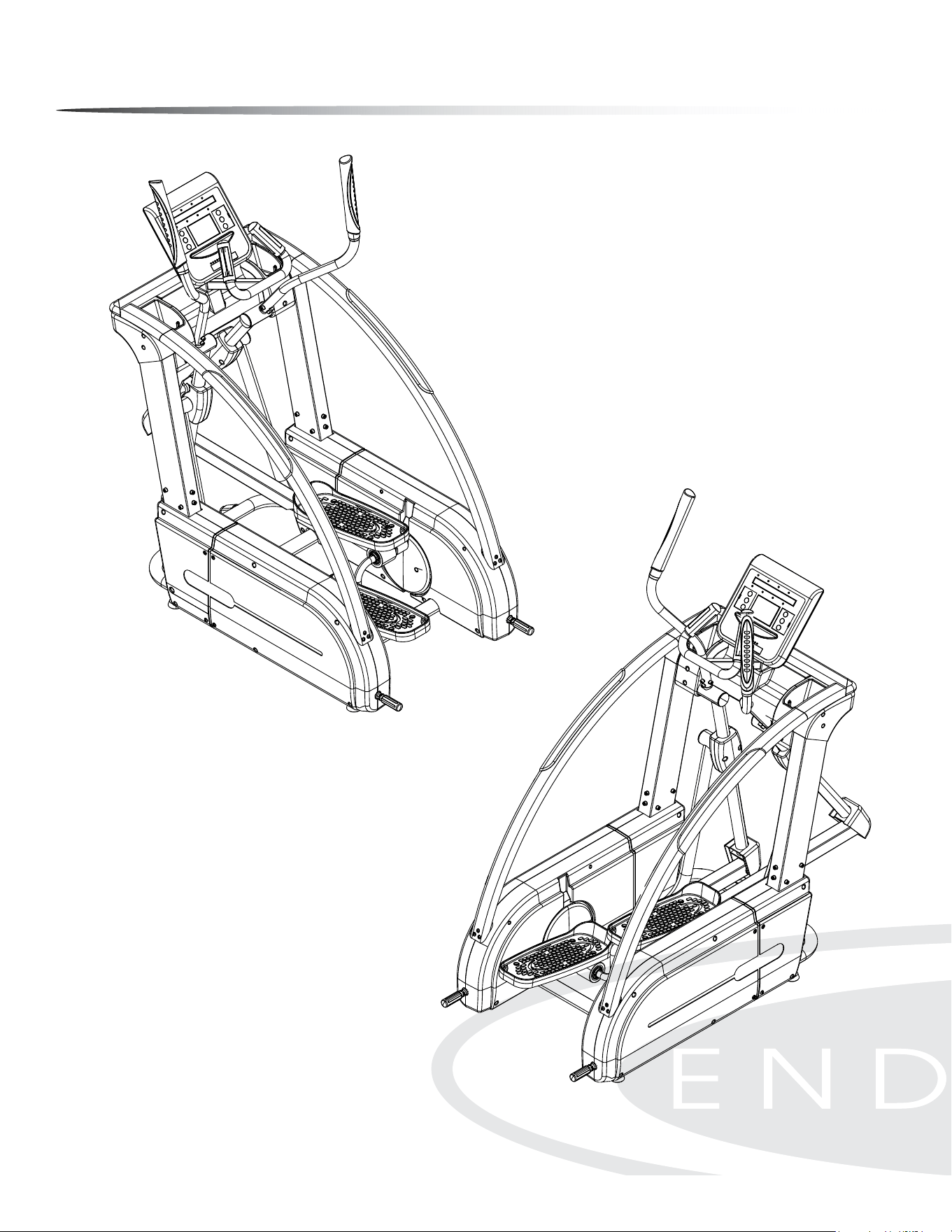
E5000 Elliptical
User Manual
v. 042910

Table of Contents
Table of Contents.........................................................................................................................
Introduction....................................................................................................................................
Important Safety Information............................................................................................
Before You Begin..........................................................................................................................
Assembly...........................................................................................................................................
Console Overview.......................................................................................................................
Console Operation.....................................................................................................................
Monitoring Your Heart Rate.................................................................................................
Chest Strap Operation............................................................................................
Stretching & Flexibility.............................................................................................................
Warm-Up/Cool Down Exercises.........................................................................................
Maintenance...................................................................................................................................
Troubleshooting Guide...........................................................................................................
Reference Drawings...................................................................................................................
2
3
4
5
6 - 25
26 - 27
28 - 36
37 - 38
39
40
41 - 47
48
49
50 - 51
Endurance
®
continually seeks ways to improve the performance, specications and product manuals in order to ensure that only superior
products are released from our factories. Please take the time to carefully read through this manual thoroughly. Instructions contained in
this document are not intended to cover all details or variations possible with Endurance
®
equipment, or to cover every contingency that
may be met in conjunction with installation, operation, maintenance or troubleshooting of the equipment. Even though we have prepared
this manual with extreme care, neither the publisher nor the author can accept responsibility for any errors in, or omission from, the informa-
tion given. Should additional information be required, or should situations arise that are not covered by this manual, the matter should be
directed to your local Endurance
®
representative, or the Service Department at Endurance
®
in Forest Park, Illinois.
c
Copyright 2009. Endurance
®
. All rights reserved. Endurance
®
reserves the right to change design and specications when we feel it will
improve the product. Endurance
®
machines maintain several patented and patent pending features and designs. All rights reserved on
all design patents and utility patents.
2

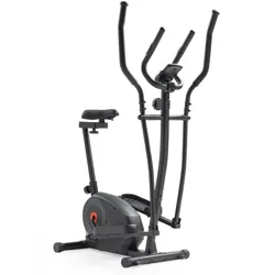
Introduction
Congratulations!!
Thank you for purchasing your new Endurance
®
Elliptical.
With state-of-the-art technique, robust frame structure and superior ergonomic
design, Endurance
®
Ellipticals set a new standard for excellence. Endurance
®
El-
lipticals can improve your quality of life by keeping you t and healthy, increasing
your energy levels and enhancing your lifestyle.
Endurance
®
wants to ensure years of quality workouts with your new Elliptical so
we recommend that you read this manual carefully and thoroughly to fully under-
stand proper use and maintenance of this product. Retain this Owner’s Manual for
future reference.
Please use this Owner’s Manual to make sure that all parts have been included in
your shipment. When ordering parts, you must use the part number and descrip-
tion from this Owner’s Manual. Use only Endurance
®
replacement parts when ser-
vicing this machine. Failure to do so will void your warranty and could result in
personal injury.
For information about product operation or service, check out the ocial Endur-
ance
®
website at www.bodysolid.com/Home/Endurance-Cardio or contact an
authorized Endurance
®
dealer or an Endurance
®
factory-authorized service com-
pany or contact Endurance
®
Customer Tech Support at one of the following:
Toll Free: 1-800-556-3113
Phone: 1-708-427-3555
Fax: 1-708-427-3556
Hours: M-F 8:30-5:00 CST
E-Mail: service@bodysolid.com
Or write to:
Endurance® Service Department
1900 S. Des Plaines Ave.
Forest Park, IL 60130 USA
3

Important Safety Information
Save this Owner’s Manual!
Before beginning any tness program, you should obtain a complete physical
examination from your physician.
When using exercise equipment, you must always take basic precautions, including the
following:
m Read all instructions before using your Endurance
®
Elliptical.
These instructions are written to ensure your safety and to protect the unit.
m DO NOT allow children on or near the equipment.
m Use the equipment only for its intended purpose as described in this guide.
m DO NOT use accessory attachments that are not recommended by the
manufacturer. Such attachments might cause injuries and will void your warranty.
m Wear proper exercise clothing and shoes for your workout, no loose clothing.
m DO NOT use cleats, spikes or any other non-athletic shoes.
m DO NOT use this product while barefoot or wearing only socks.
m Use care when getting on or o the unit.
m DO NOT overexert yourself or work to exhaustion. If you experience any pain such
as chest pains, nausea, dizziness, shortness of breath or abnormal symptoms, stop
your workout immediately and consult your physician before continuing.
m Never operate the unit when it has been dropped or damaged.
Return the equipment to a service center for examination and repair.
m Never drop or insert objects into any opening in the equipment.
m Always check the unit for loose components before each use.
m DO NOT turn pedals by hand.
m DO NOT use the equipment outdoors or near water. It is imperative that your
Endurance
®
Elliptical is used in a climate controlled environment. If your elliptical
has been exposed to colder temperatures or to high moisture climates, it is strongly
recommended that the elliptical is brought to room temperature before use. Failure
to use this equipment in a climate controlled environment may cause premature
electronic failure.
m Unplug the elliptical before moving or cleaning it. DO NOT pull the power cord to
move this product. Keep the power cord away from heated surfaces.
m Endurance
®
recommends that a mat is placed under the unit to protect the oor or
carpet and for easier cleaning.
Endurance
®
Ellipticals are designed for your enjoyment. By following these precautions and
using common sense, you can have many safe and pleasurable hours of healthful exercise
with your Endurance
®
Elliptical.
4

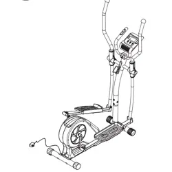
Before You Begin
The Endurance
®
E5000 is carefully tested and inspected before shipment. We have
shipped the unit in several pieces that require assembly. Carefully unpack the unit in
a clear area and lay the pieces on the oor near the area where you plan to use the
equipment. Remove the packing material. Do not dispose of the packing material
until assembly is complete and the unit is working properly. Place the unit on a clean
level surface for assembly. Before assembling, the unit should be placed as close as
possible to its nal location. Be careful to assemble all components in the sequence
presented in this guide.
PERSONAL SAFETY DURING ASSEMBLY
m It is strongly recommended that a qualied dealer assemble the equipment.
Assistance is required.
m Before beginning assembly, please take the time to read the instructions
thoroughly.
m Read each step in the assembly instructions and follow the steps in sequence.
Do not skip ahead. If you skip ahead, you may learn later that you have to
disassemble components and that you may have damaged the equipment
which will void the warranty.
m Assemble and operate the Endurance
®
Elliptical on a solid, level surface.
Locate the unit a few feet from the walls or furniture to provide easy access.
AFTER ASSEMBLY
Once the unit is assembled, you should check all functions to ensure correct opera-
tion. If you experience problems, rst recheck the assembly instructions to locate
any possible errors made during assembly. If you are unable to correct the problem,
call the dealer from whom you purchased the machine or call Endurance
®
Customer
Tech Support Hot Line Toll Free at: 1-800-556-3113.
5

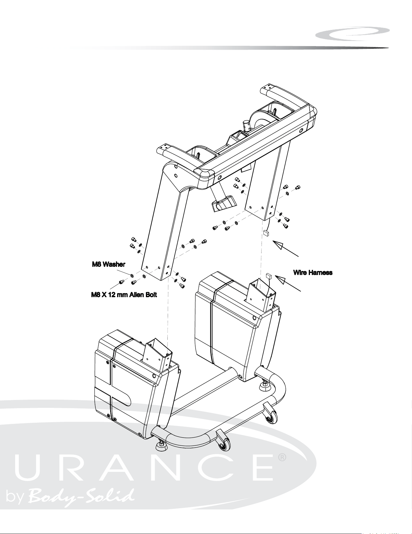
Step 1
A. Carefully lift the Upright Frame Assembly above the front of the
Base Frame.
B. Attach wire harness as shown.
NOTE: A second person is required.
C. Slide the Upright Frame onto the Base Frame.
D. Secure the Upright Frame Assembly to the Base Frame using:
Sixteen M8x12 Allen Bolt
Sixteen M8 Washer
6
Step 1
7

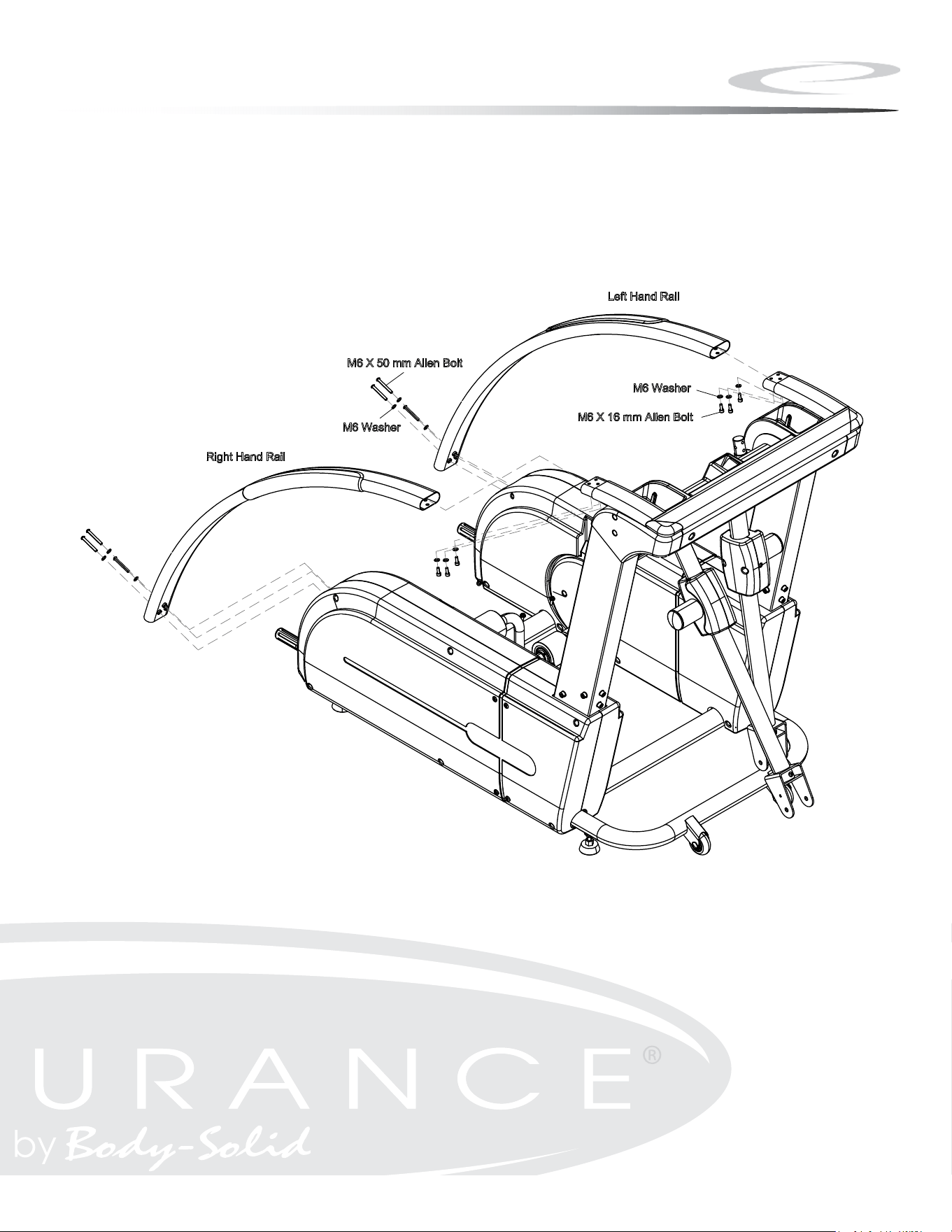
Step 2
A. Connect the Left Handrail to the Mainframe using:
Three M6x16 Allen Bolt
Six M6 Washer
Three M6x50 Allen Bolt
B. Connect the Right Handrail to the Mainframe using:
Three M6x16 Allen Bolt
Six M6 Washer
Three M6x50 Allen Bolt
8
Step 2
9

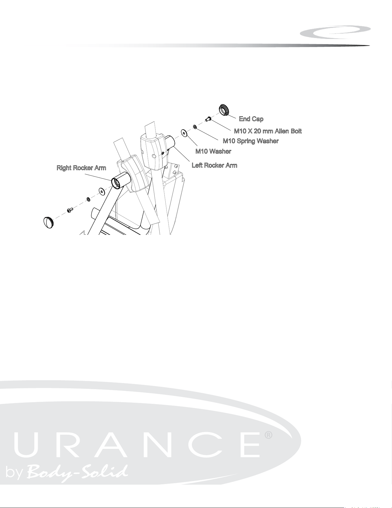
Step 3
A. Connect Right Rocker Arm and secure using:
One M10 Washer
One M10 Spring Washer
One M10x20 Allen Head Bolt
B. Insert the End Cap into Right Rocker Arm as shown.
C. Connect Left Rocker Arm and secure using:
One M10 Washer
One M10 Spring Washer
One M10x20 Allen Head Bolt
D. Insert the End Cap into Left Rocker Arm as shown.
10
Step 3
11

Step 4
A. Lift Pedal and place Left Linkage onto Sleeve and align holes.
B. Secure Linkage to unit using:
Four M8*12 Hex Head Bolt
Four M8.4 Flat Washer
NOTE: Repeat for right linkage.
12

Step 4
13
New Step4

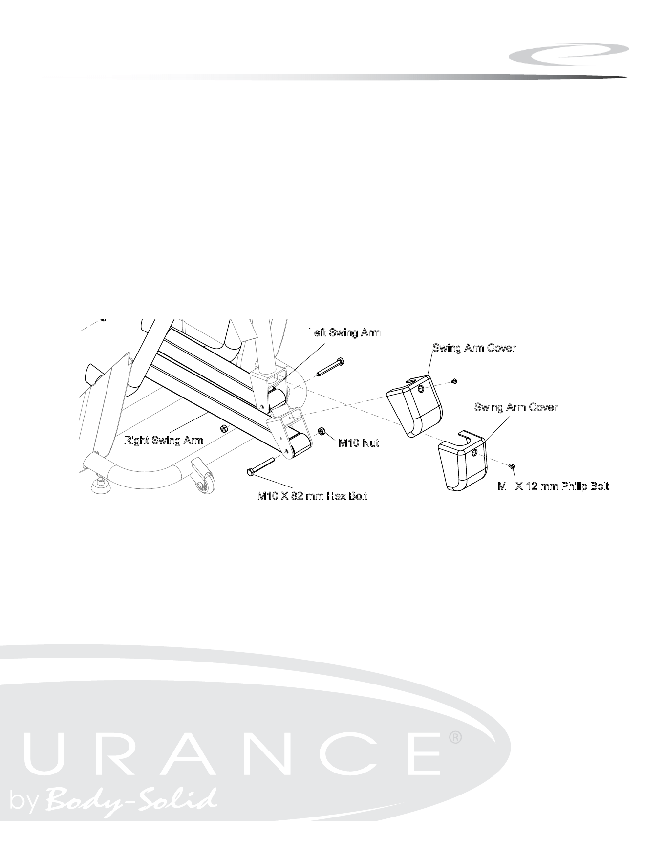
Step 5
A. Secure Left Swing Arm by using:
One M10x82 Hex Head Bolt
One M10 Nut
B. Secure Right Swing Arm by using:
One M10x82 Hex Head Bolt
One M10 Nut
C. Install both Swing Arm Covers as shown using:
Two M5x12 Phillips Head Bolt
14
Step 5
15
5

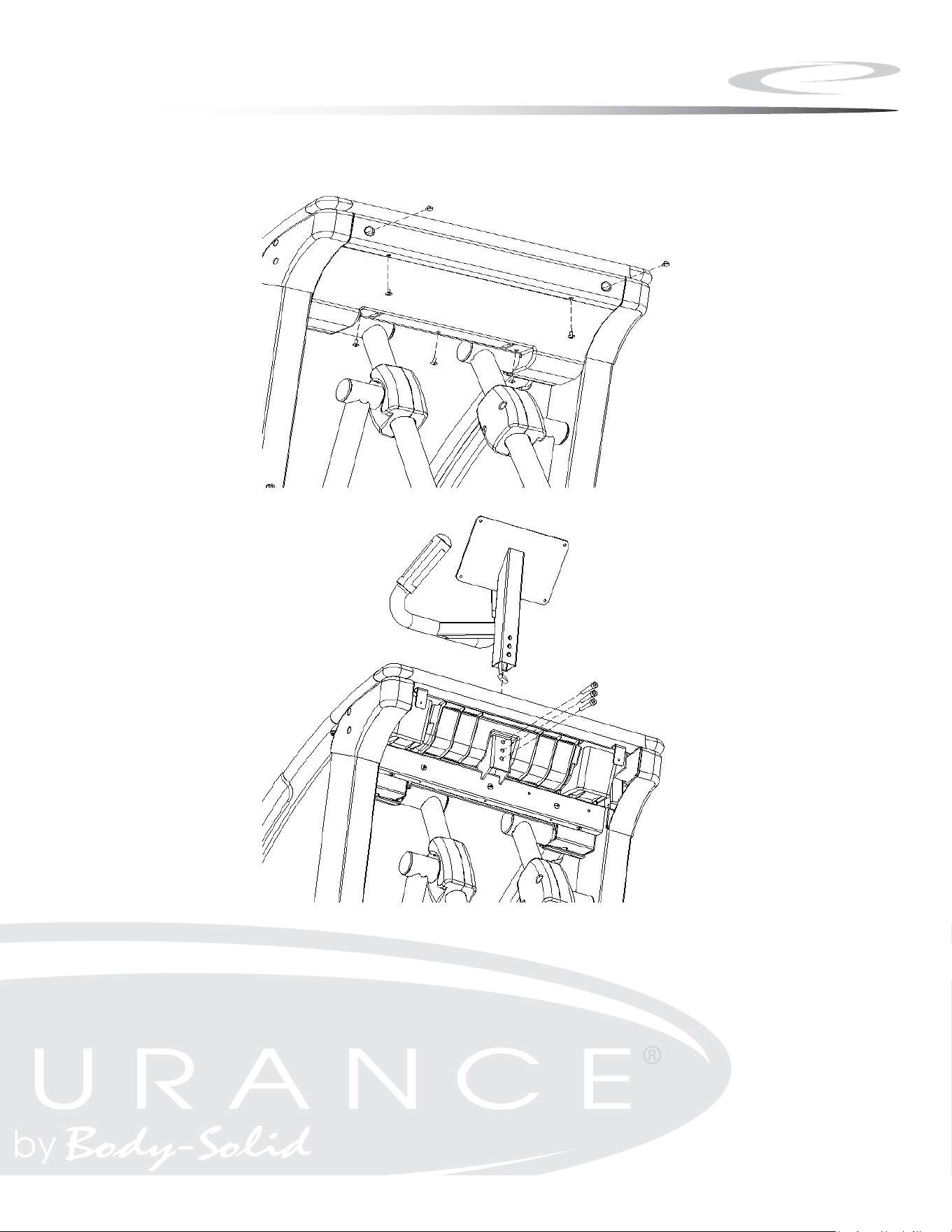
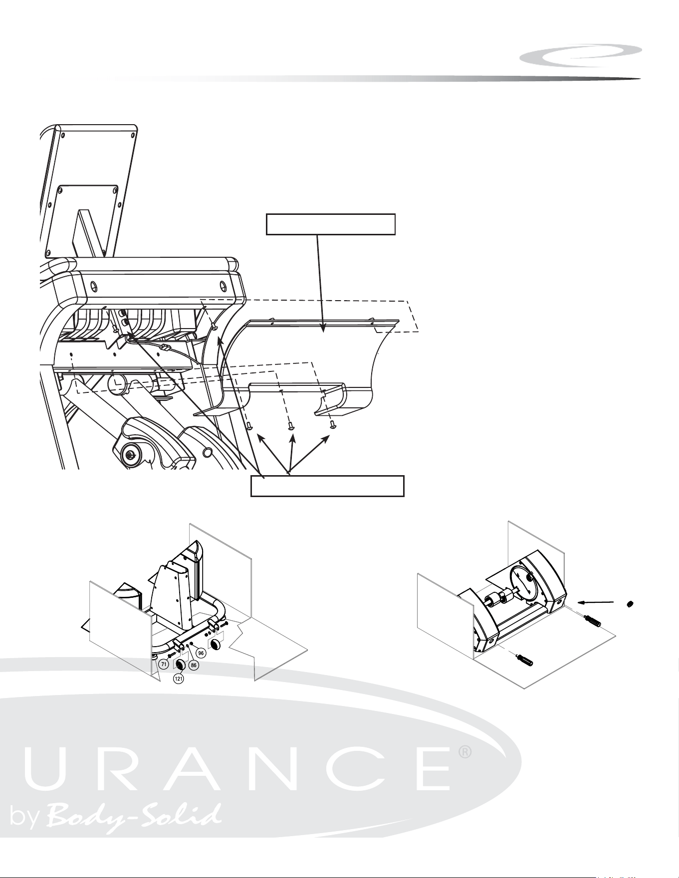
Step 6
A. Remove Rear Cover from the unit by removing ve screws.
B. Attach Console Tube to Main Frame.
C. Slide Tube down into Main Frame.
D. Secure using:
Three M8*50 Hex Head Bolt
NOTE: Cable should extend through the bottom and the top of the
Console Tube.
16
Step 6
17

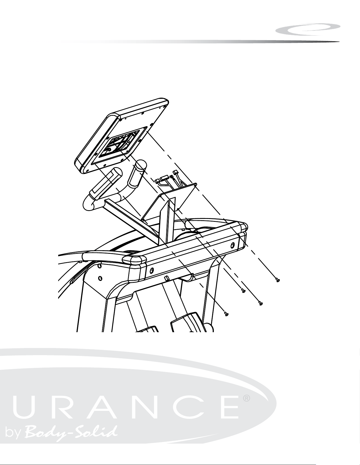
Step 7
A. Connect all cables to the console as shown.
B. Attach the Console to the Console tube using:
Four M5*12 Philip Head Screw
NOTE: Ensure that all wires are secure inside console.
Be careful not to pinch wires.
18
Step 7
19
角 法 單 位 次版 比 例
姓 名
日 期
設 計
校 對
核 准
量數
表面處理
材 質
機 種
零 件 名 稱
中文
英文
零
件
編
號
變更處
原 尺 寸
更 改 尺 寸 更 改 原 因
單據號碼
日 期
負 責 人
STEP 7
M5x0.8-12
4PC
CONSOLE

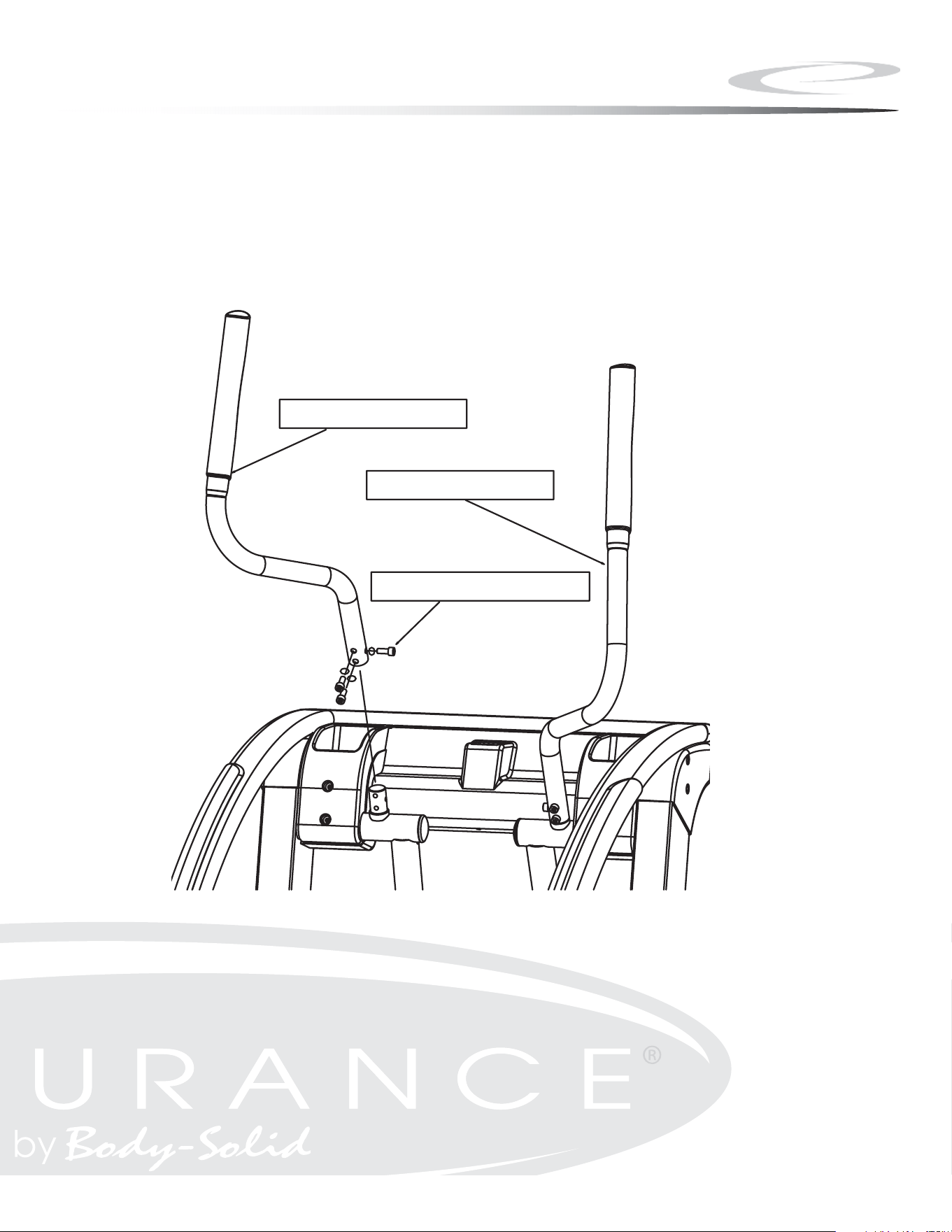
Step 8
A. Attach Handlebars to Main Frame using:
Three M8*16 Hex Head Bolt
Three M8 Arc Washers
B. Repeat for other handlebar.
20
Step 8
21
M8*20mm Hex Bolt
Right Handlebar
Left Handlebar
16

Step 9
A. Attach the Rear Cover to the Main Frame using:
Five M5*12 Philip Head Screw
NOTE: Do not force Rear Cover back into place, this will damage the
Rear Cover.
B. Install Transport Wheels (121) using:
Two 71 (M8x45 carriage bolt)
Two 86 (M8.4 at washer)
Two 97 (M8 nylon lock nut)
C. Thread handles into Main Frame.
D. Move machine to desired area.
E. Remove handles from Main Frame.
F. Insert provided end caps as shown.
NOTE: Some components may be pre-installed.
22
Step 9
23
Note:
REAR COVER
M5*12MM SCREW
*NOTE: Some components may be pre-installed.

Step 10
A. Level machine so that no wobble is present.
B. Leveler feet screw in and out to level the machine.
C. After the machine is level, tighten the leveler nut to secure levelers
in place.
24
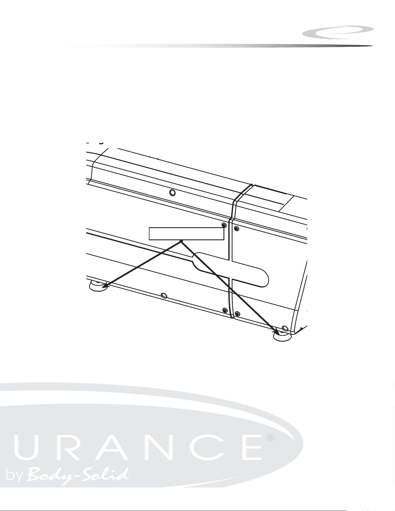
Step 10
25
Note:
Figure 7
LEVELER
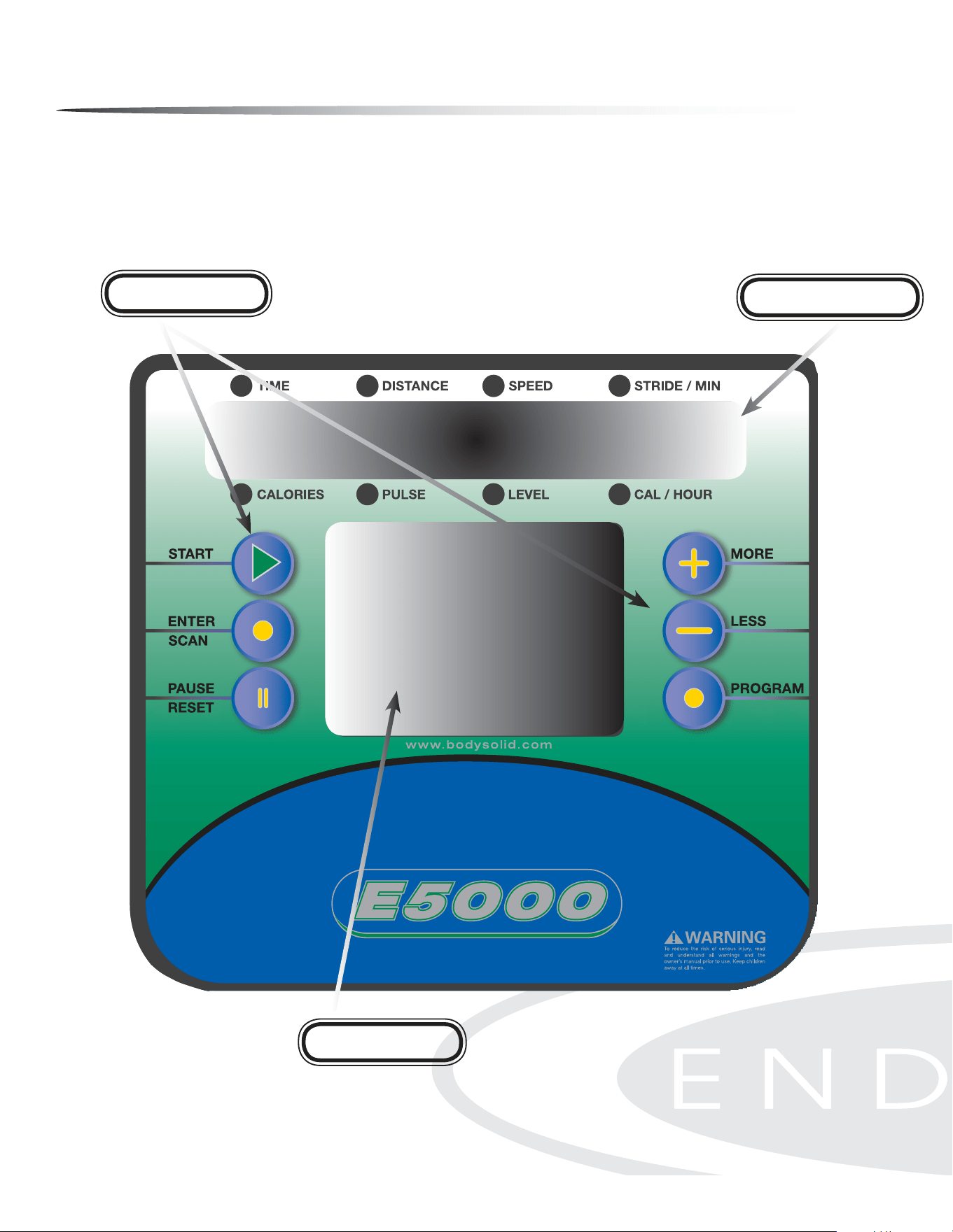
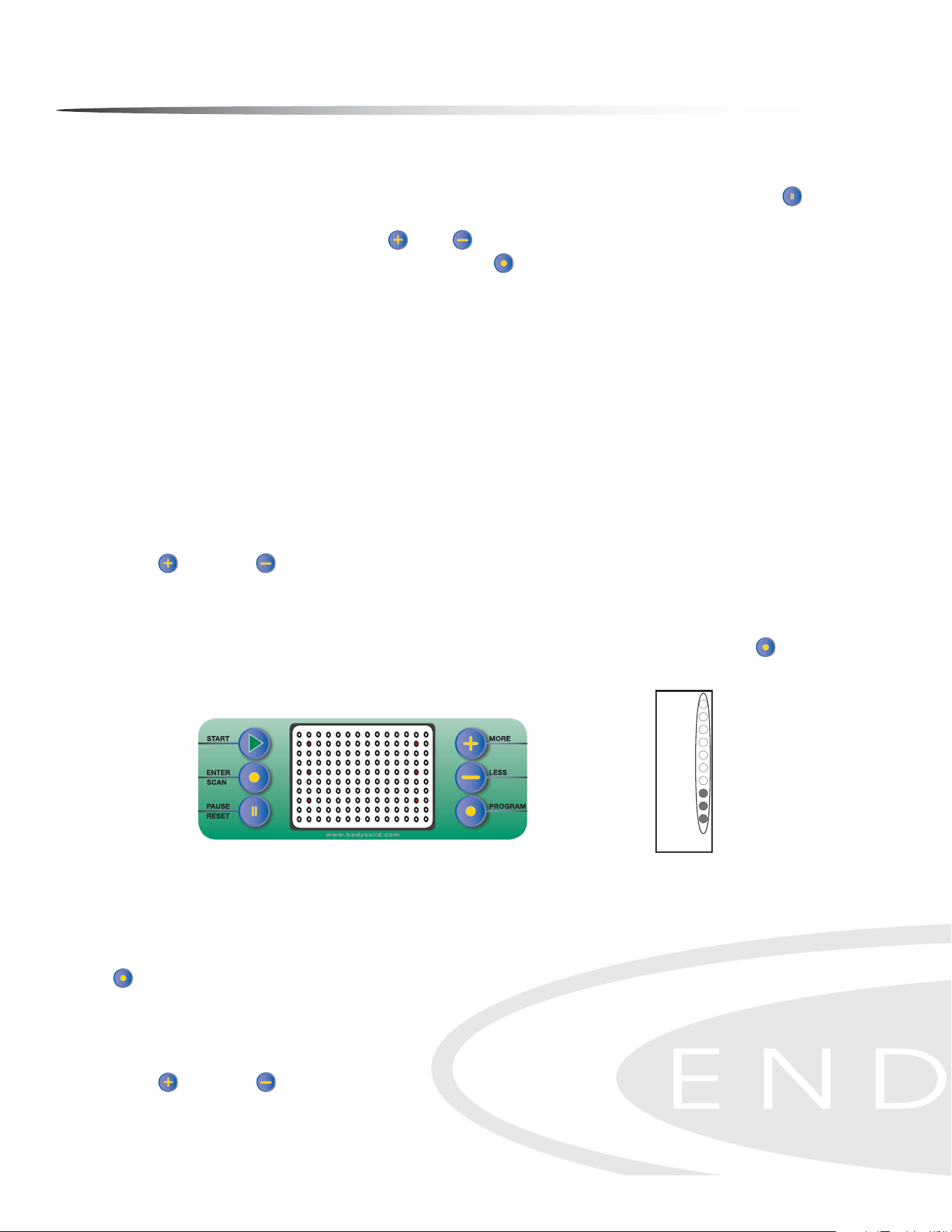
Console Overview
Take a few moments to review the console layout. Below is an overview of the con-
sole buttons and their dierent functions.
Message Window
Prole Window
Control Buttons
26

Console Overview
START
Press the START button to enter the Quick Start Mode.
In Pause Mode, the START button is used to resume the exercise session.
ENTER/SCAN
In Program Mode, the ENTER/SCAN button is used to conrm the values you set.
During exercise, press the ENTER/SCAN button once and the main console window
is placed in Auto Scan Mode. The display will change every four seconds from TIME/
DISTANCE/SPEED/STRIDES PER MINUTE to CALORIES/PULSE/LEVEL/CALORIES PER
HOUR. To exit Auto Scan Mode and enter Manual Scan Mode, press and hold the ENTER/
SCAN button for two seconds. The console will beep twice to conrm that the selec-
tion was entered. Manual Scan Mode allows you to toggle the display from TIME/DIS-
TANCE/SPEED/STRIDES PER MINUTE to CALORIES/PULSE/LEVEL/CALORIES PER HOUR
by pushing the ENTER/SCAN
button when the change in display is desired. To return
to the Auto Scan Mode, press and hold the ENTER/SCAN button for two seconds. The
console will beep twice to conrm that the selection was entered.
PAUSE/RESET
During exercise, the PAUSE/RESET button is used to pause the workout.
In Pause mode, the PAUSE/RESET button is used to reset the program time and work-
out data to zero.
In Program mode, the PAUSE/RESET button is used to reset values to their default set-
ting.
CAUTION: In User 1 and User 2 programs, the user prole data will be also cleared
when pushing the PAUSE/RESET button.
MORE/LESS
In Program mode, the MORE /LESS buttons are used to increase/decrease TIME,
WEIGHT and AGE.
During exercise, the MORE /LESS buttons are used to increase/decrease the resis-
tance level from 1 to 20. Press and hold the MORE /LESS buttons for two seconds to
rapidly increase/decrease values.
PROGRAM
In Program Mode , the PROGRAM button is used to toggle between workout pro-
grams. The program selected is displayed in the MESSAGE WINdOW. The program prole
is displayed in the PROfILE WINdOW.
27

Console Operation
There are two information windows on the console:
MESSAGE WINDOW
The MESSAGE WINdOW displays Program Names, Messages, TIME, DISTANCE, SPEED,
STRIDE/MIN, CALORIES, PULSE, RESISTANCE LEVEL and CALORIE/HOUR.
PROFILE WINDOW
This 10 X 14 LED PROfILE WINdOW displays Program Prole, Tension (Resistance) Bar,
Heart Rate Bar (HR Programs only), Lap Progress Display and Lap Counter. The PROfILE
WINdOW toggles between program prole (displayed for 10 seconds in window) and
lap counter (displayed for 30 seconds in window), except in Heart Rate Programs.
NOTE: When changing resistance levels in preset programs, the change will not show
in the program prole. Changes in resistance will show in the rst column when lap
progress function is shown.
28
Console Prole Window
Console Message Window
Console Operation
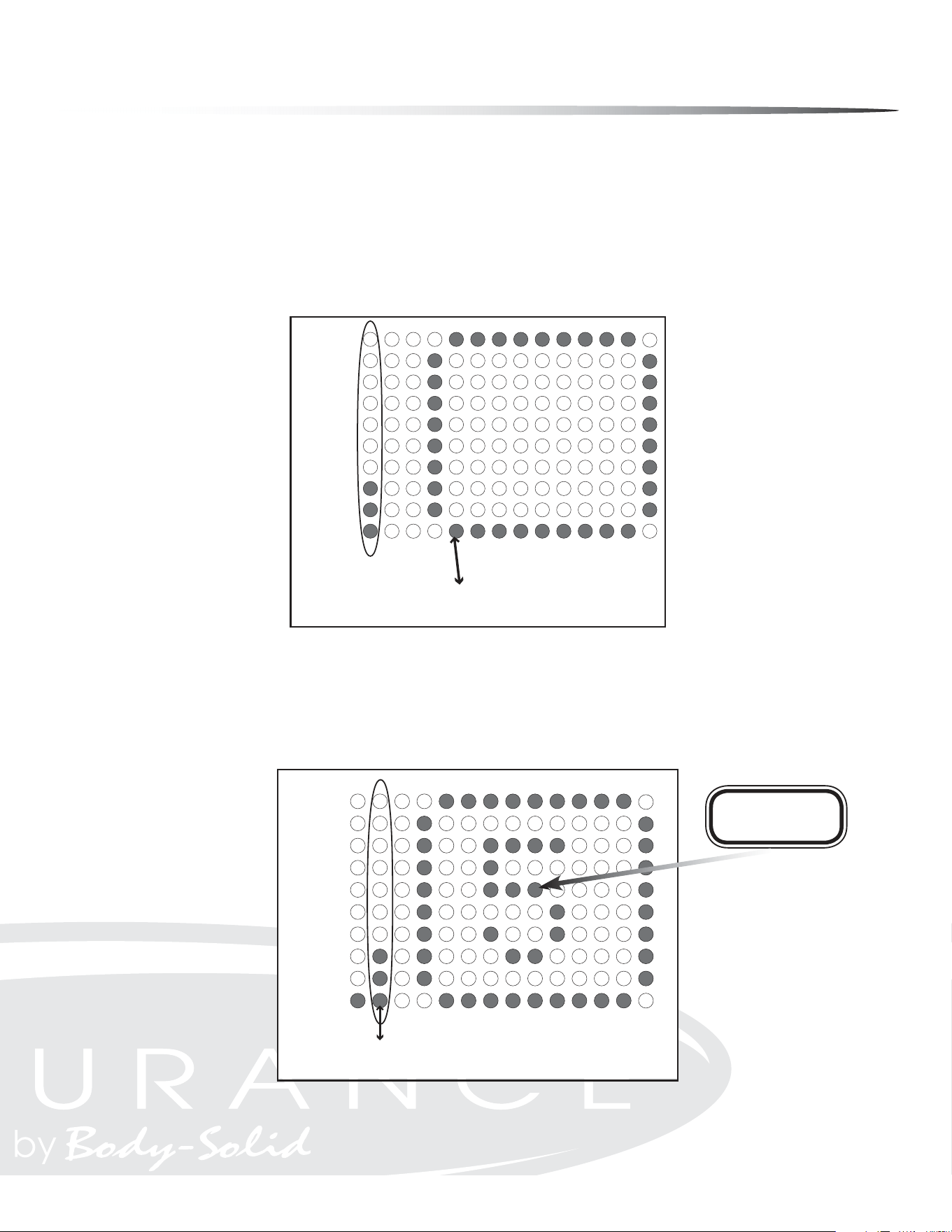
LAP DISPLAY
Lap Display shows your progress around a virtual track. Lap Display also shows the
resistance level in the rst column. Every dot in the resistance column represents an
increment of two resistance levels. Resistance is adjustable from 1-20. One dot on the
lap counter is equal to 15 revolutions and one revolution is equal to 2 steps. The track
will blink showing the exerciser’s current position.
LAP DISPLAY/COUNTER
In Heart Rate Mode the lap progress display also shows % of Maximum Heart Rate
and Resistance level.
Lap Counter
91-95
86-90
81-85
76-80
71-75
66-70
61-65
56-60
51-55
<50
% of Maximum
Heart Rate
Lap Counter
Current Lap
Value Starts At Zero
% of Maximum
Heart Rate
Lap Progress Display
19-20
17-18
15-16
13-14
11-12
9-10
7-8
5-6
3-4
1-2
Lap Progress
Starts Here
Tension
Level
Lap Progress Display
Resistance
Level
Lap Progress
Starts Here
29

Console Operation
QUICK START MODE
The Quick Start Program allows the user to quickly start using the machine without
the use of preset programs. To enter Quick Start (Manual) Mode: Plug power adapter
into wall outlet. Plug the adapter cord into the power input located on the lower
front-left side of the unit. The MESSAGE WINdOW will display “PRESS PROGRAM KEY TO
BEGIN”. Press the START button instead. Start exercising. The Resistance Level can
be changed at any time by pressing the MORE /LESS buttons. Time is set at 30 min-
utes. Weight is set at 150 lb.
MANUAL MODE
This program allows the user complete control over their workout. The user must
make all resistance adjustments using the MORE /LESS buttons. Follow directions
in the Program Mode section to enter and set values in Manual Mode.
PROGRAM MODE
There are six preset Programs. The preset programs are MOUNTAIN, HILL, RANDOM,
INTERVAL SPEED TRAINING, INTERVAL, INTERVAL MOUNTAIN.
To enter Program Mode:
The MESSAGE WINdOW will display “PRESS PROGRAM KEY TO BEGIN”. Press the PROGRAM
button until desired program name shows in the MESSAGE WINdOW. The program
prole will show in the PROfILE WINdOW. See the referenced charts for program names
and resistance proles. When the program you wish to use is displayed in the MES-
SAGE WINdOW, press the ENTER/SCAN button to conrm program selection. TIME is
displayed in MESSAGE WINdOW. Use the MORE /LESS buttons to set the desired TIME.
Press the ENTER/SCAN button to conrm the desired TIME setting. Default TIME is 30
minutes. TIME settings can range from 1 minute to 99 minutes.
NOTE: If the TIME entered is less than or equal to 14 minutes, each column in
the program prole equals 1 minute.
If the TIME entered is greater than 14 minutes, each column equals
TIME/14.
WEIGHT is shown in the MESSAGE WINdOW. Use the MORE /LESS buttons to set weight.
Press the ENTER/SCAN button to conrm WEIGHT setting. The default WEIGHT is 150
pounds. WEIGHT settings can range from 70 Lb to 332 Lb.
AGE will show in MESSAGE WINdOW. Use the MORE /LESS buttons to set the AGE. Press
ENTER/SCAN to conrm AGE setting. The default AGE setting is 30. AGE settings can
range from 10 to 99 years of age. Press the START
button to exit Program Mode and
begin the exercise session.
30
Console Operation
MOUNTAIN
This program takes the user gradually up to a high resistance level, then brings the
resistance level back down to the starting point. This program simulates what one
might encounter on a true mountain course. This is a dicult program since higher
tension levels are maintained for long periods of time.
HILL
This program takes the user through two hill proles. Resistance changes are small
during this program. This is a good program to get started with or for someone look-
ing for a lower stress workout.
RANDOM
This program randomly generates a new program prole every time it is chosen. This
allows you to keep the workouts fresh and motivating. When you scroll thru the pro-
grams to reach the RANDOM program, you will be able to see the program prole.
If this prole is not to your liking, simply scroll thru the programs again and a new
RANDOM program will be generated. The RANDOM program will be dierent every
time you use it.
or Information on Heart Rate Programs see HEART RATE Programs section of this manual.
MOUNTAIN
INTERVAL
INTERVAL MOUNTAIN
INTERVAL SPEED
TRAINING
HILL
RANDOM
Example Only
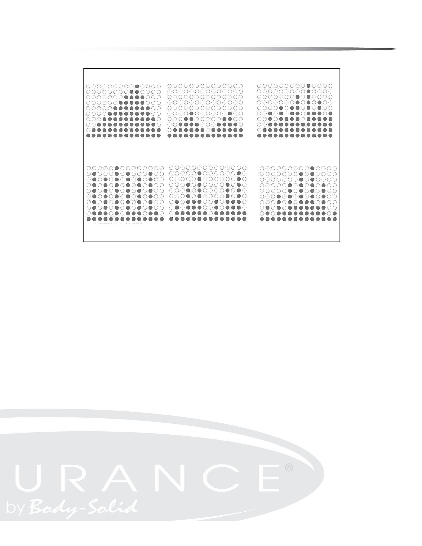
PROGRAM PROFILES
PROGRAM PROFILES
MOUNTAIN
HILL
RANDOM
(RANDOM EXAMPLE SHOWN)
INTERVAL SPEED
TRAINING
INTERVAL
INTERVAL MOUNTAIN
RANDOM
Program Prole Chart
31

Console Operation
INTERVAL PROGRAMS OVERVIEW
These programs give users the best of both worlds. Lower intensity levels can provide
eective fat burning while higher intensity levels can provide eective cardiovascu-
lar training. The E5000 combines these benets in three eective Interval programs.
INTERVAL
This program simulates interval training thru a series of two hill proles.
INTERVAL MOUNTAIN
This program simulates interval training thru a dicult mountain prole.
INTERVAL SPEED TRAINING
This program simulates interval training with more extreme levels of high and low
intensity levels.
USER PROFILES:
U1/U2
User Proles U1 and U2 allow you to customize and save an exercise session.
Entering Data Into User Programs:
Scroll thru programs to U1 or U2. If no prole has been saved, the message window
will scroll “EMPTY FILE PRESS START TO BUILD A NEW PROFILE”. Press the START but-
ton. You may make changes to the resistance level at any time during your exercise
session. One you press the PAUSE/RESET button and exit the program, the data is
automatically saved.
Clearing A Saved User Program:
Press the PROGRAM button to scroll to U1 or U2 program. Press the ENTER/SCAN
button to select the chosen program. Press and hold the PAUSE/RESET button for 2
seconds. The console will beep twice to conrm that the selection was entered.
32

Console Operation
DURING OPERATION
The Console will display and update calculated workout data in each of the windows.
The Console will continue to count down until TIME has reached 0:00. Use the MORE
/LESS buttons to adjust the resistance level at any time during your workout ses-
sion. In the PROfILE WINdOW, the current column will be ashing.
During non-heart rate programs, the PROfILE WINdOW will toggle between the pro-
gram prole and the track display. The program prole will actively display for 10
seconds while the track display will be active for 30 seconds.
During heart rate programs, the PROfILE WINdOW will only show the track display.
The user may change the program selection during an exercise session by pressing
the PROGRAM button until a new program is selected. The new selected program
will start from the beginning of the prole. All workout data will continue to add to
previous values. If you burned a set amount calories during original program this
value will not reset to zero.
The console will automatically shut o after 4 minutes of inactivity. Press any button
to bring the console back to full functionality.
33

34
Console Operation
HEART RATE PROGRAMS (See the MONITORING YOUR HEART RATE section for more information)
Heart rate control programs are designed to automatically change resistance to keep
your heart rate at a predetermined level based on the selected Heart Rate program.
Each Heart Rate program is designed with a specic goal in mind.
If no Heart Rate signal is detected for 10 seconds, the MESSAGE WINdOW will show “NO
DETECTED HR”. If this continues for 40 seconds, the MESSAGE WINdOW will show “ABORT
PROGRAM” for 3 seconds then interrupt the Heart Rate Control program and return
to Program Mode.
HOW HEART RATE PROGRAMS WORK
Change in Heart Rate (
HR) = Beats per minute dierence between
Target Heart Rate (THR) and Current Heart Rate (CHR).
or : HR = THR (bpm) - CHR (bpm)
The Heart Rate Programs will behave in the following manner:
HR equal to 5
Resistance level stays the same. The MESSAGE WINdOW will show “IN HR TARGET” for 3
seconds then toggle back to workout information.
HR greater than 5
Resistance level decreases. If the current resistance level is 1, then the
MESSAGE WINdOW will display “STRIDE SLOWER” for 3 seconds. The console’s computer
will check the user’s Heart Rate every 40 seconds and adjust the resistance level to t
the Target Heart Rate.
HR less than 5
Resistance level will increase. If the current resistance level is 20, the MESSAGE WIN-
dOW will show “STRIDE FASTER” for 3 seconds. The console’s computer will check the
user’s Heart Rate every 40 seconds and adjust the resistance level to t the Target
Heart Rate.
% (TARGET HEART RATE)
% Target Heart Rate allows the user to select a percentage of Maximum Heart Rate
(See section titled MONITORING YOUR HEART RATE for more information) that would
like to be maintained during the exercise session. The percentage range can be var-
ied from 50% to 85%.
HR 80% (CARDIO)
HR 80% maintains the Target Heart Rate at 80% of the Maximum Heart Rate by au-
tomatically adjusting resistance levels. This program provides for a high intensity,
cardiovascular workout.
35
Console Operation
HR 65% (FAT BURN)
HR 65% maintains the Target Heart Rate at 65% of the Maximum Heart Rate by au-
tomatically adjusting the resistance levels. This program provides the ultimate fat
burning workout.
HR HILL (65-75-85%)
HR Hill simulates hill training by changing the Target Heart Rate thru 3 dierent per-
centages. The changes will occur as follows:
65% - 75% - 85% - 75% - 65% -75% - 85% etc.
Each percentage will be held for 3 minutes before changing to the next percentage.
HR INT (HILL INTERVAL)
The HR INTERVAL program alternates between 65% and 85% of your Max HR. This
program provides an excellent fat burn and cardiovascular workout. Each percent-
age will be held for 4 minutes before alternating to the next percentage.
TARGET HEART
RATE
HEART RATE
CARDIO 80%
HEART RATE
FAT BURN 65%
HEART RATE
HILL 65-85%
HEART RATE
INTERVAL 65-85%
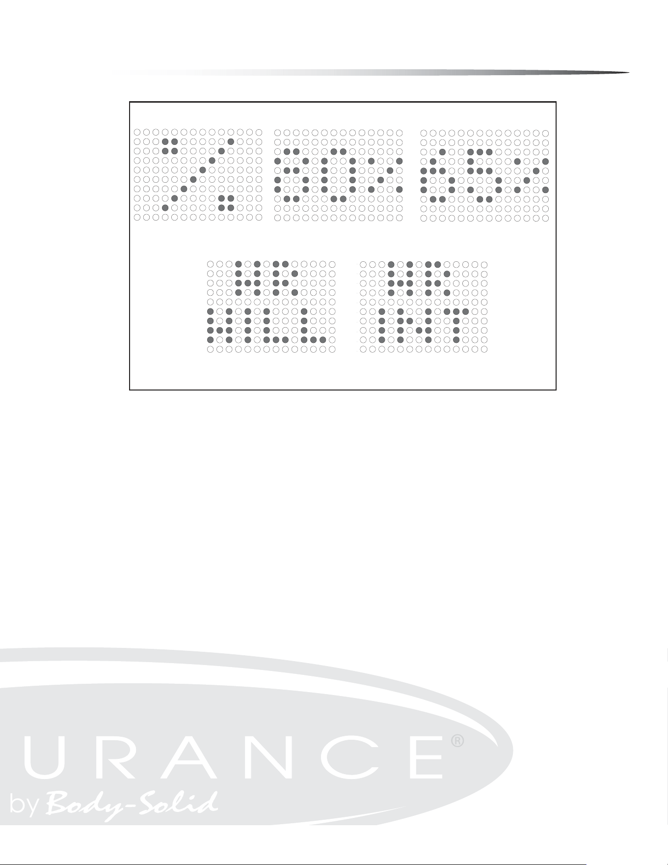
HEART RATE PROGRAM PROFILES
HEART RATE
TARGET HEART
RATE
Heart Rate Program Prole Chart
HEART RATE
CARDIO 80%
HEART RATE
FAT BURN 65%
HEART RATE
INTERVAL 65-85%
HEART RATE
HILL 65-85%
HEART RATE PROGRAM PROFILES
Console Operation
STANDARD TO METRIC CONVERSION
The console allows the user to display the readout in either standard or metric units
depending on the user’s needs. To adjust the readout, press the PAUSE/RESET button
for 2 seconds. The current readout, whether standard or metric, is displayed on the
MESSAGE WINdOW. Use the MORE /LESS buttons to change the unit of measure. To
conrm the selection, press the ENTER/SCAN button.
CONSOLE TESTING
Display Test
The display test allows the user the ability to test the MESSAGE WINdOW and the PRO-
fILE WINdOW display for correct functionality. The display test is used perform a visual
hardware check by allowing the MESSAGE WINdOW and the PROfILE WINdOW display the
opportunity to display every LED in predetermined sequences. The MESSAGE WINdOW
will display and cycle through the characters <0, 1, ... , 9> and <A, B, ... , F>. The PRO-
fILE WINdOW will display and cycle through all the columns and rows illuminating an
entire column or row with every cycle. To access the display test, rst remove power
and then reapply power to the elliptical. Once the elliptical is powered on, press the
MORE and LESS buttons together and hold for 2 seconds.
Button Test
The button test allows the user to determine if the console’s buttons are fully func-
tional. Once the display test has been performed, press the ENTER/SCAN button to
activate the button test. LEDs will be displayed next to the buttons as shown in the
gure below.
Pressing each button individually will turn o the adjacent LED signifying that each
of the pressed buttons are active. When all the console buttons have been pressed,
all the LEDs should be o in the PROfILE WINdOW display indicating that the buttons
are working correctly. To exit this test once it has been completed, press the PROGRAM
button.
Resistance Motor Test
Once the Button Test is complete, the Resistance Motor Test mode is activated. Per-
form the resistance motor test to verify functionality of the resistance motor. Use the
MORE and LESS buttons to change the motor resistance. The LEDs will display the
resistance value as it is increased. See the Resistance Level Chart for reference.
Button Test Display
19-20
17-18
15-16
13-14
11-12
9-10
7-8
5-6
3-4
1-2
Tension
Level
Resistance Level Chart
Resistance
Level
36

Monitoring Your Heart Rate
To obtain the greatest cardiovascular benets from your exercise workout, it is im-
portant to work within your target heart rate zone. The American Heart Association
(AHA) denes this target as 60% -75% percent of the Maximum Heart Rate.
The Maximum Heart Rate may be roughly calculated by subtracting the user’s age
from 220.
The Maximum Heart Rate and aerobic capacity naturally decreases as the user ages.
This may vary from one person to another, but use this number to nd your approxi-
mate eective target zone. For example, the Maximum Heart Rate for an average 40
year-old is 180 bpm. The target heart rate zone is 60%-75% of 180 or 108-135 bpm.
See the FITNESS SAFETY section.
Before beginning a workout, check the normal resting heart rate. The user can place
their ngers lightly against the neck or wrist over the main artery. After nding the
pulse, count the number of beats in 10 seconds. Multiply the number of beats by six
to determine your pulse rate per minute. It is recommend to take a heart rate mea-
surement at rest, after warming up, during the workout and two minutes into cooling
down after the workout, to accurately track progress as it relates to better tness.
During your rst several months of exercising, the AHA recommends aiming for the
lower part of the target heart rate zone - 60%, then gradually progressing up to 75%.
According to the AHA, exercising above 75% of the Maximum Heart Rate may be too
strenuous unless the user is in top physical condition. Exercising below 60% of the
maximum will result in minimal cardiovascular conditioning.
CHECK YOUR PULSE RECOVERY RATE
If your pulse is over 100 bpm ve minutes after stopping exercising, or if it’s higher
than normal the morning after exercising, the user’s exertion may have been too
strenuous for their current tness level. Rest and reduce the intensity next time.
37
Monitoring Your Heart Rate
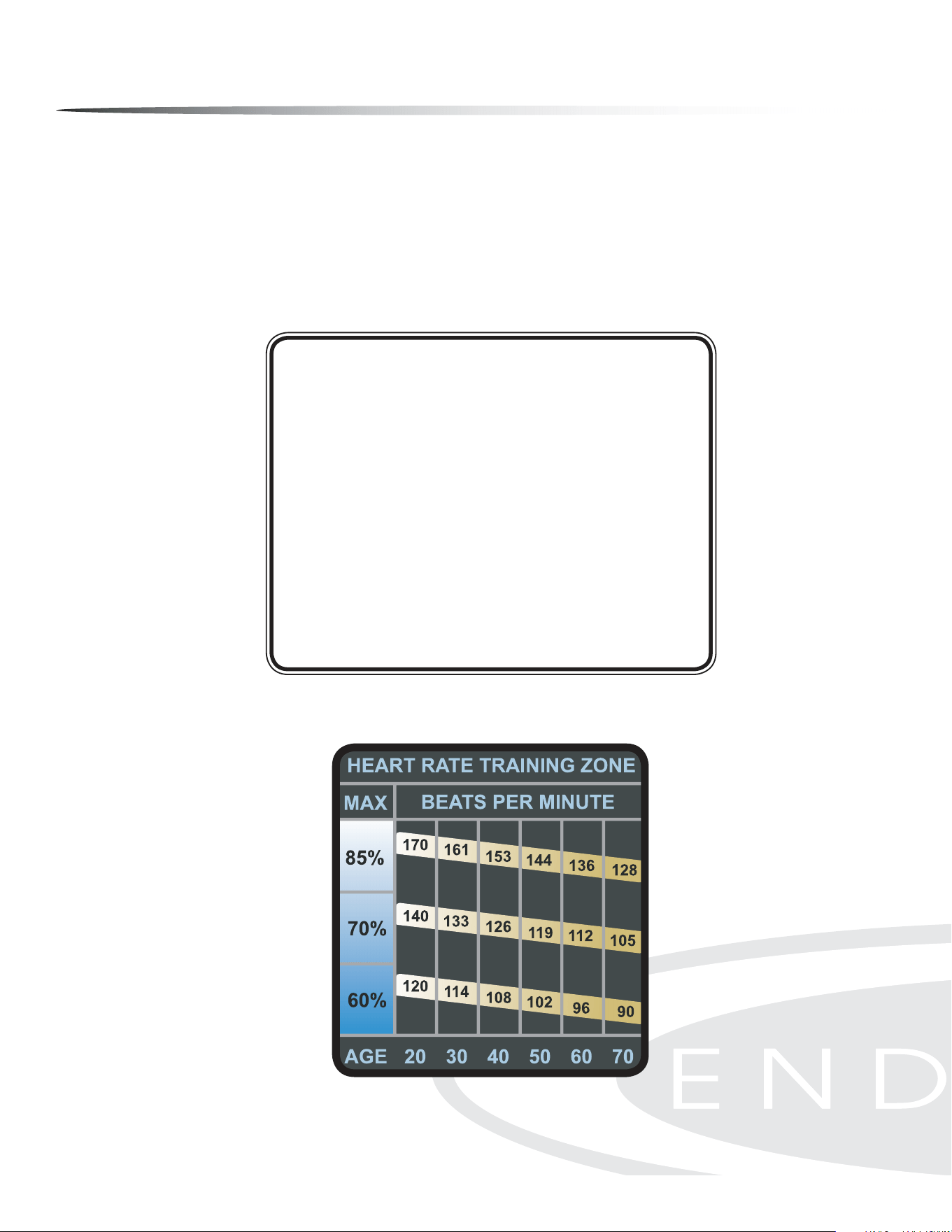
FITNESS SAFETY
The Heart Rate chart indicates average rate zones for dierent ages. A variety of dif-
ferent factors (including medication, emotional state, temperature and other con-
ditions) can aect the target heart rate zone that is best for you. Your physician or
health care professional can help you determine the exercise intensity that is appro-
priate for your age and condition.
(MHR) = Maximum Heart Rate
(THR) = Target Heart Rate
220 - Age = Maximum Heart Rate (MHZ)
MHZ x .60 = 60% of your Maximum Heart Rate.
MHZ x .75 = 75% of your Maximum Heart Rate.
For example, if you are 30 years old, your calculations will be as follows:
220 - 30 = 190
190 x .60 = 114 (Low End or 60% of MHZ)
190 x .75 = 142 (High End or 75% of MHZ)
30 Year-Old (THR) Target Heart Rate would be 114-142
Maximum Heart Rate (MHR) Calculation
Heart Rate Training Zone Chart
38
Chest Strap Operation
Your Endurance
®
Elliptical has the capability to determine Heart Rate with the use of
a Heart Rate Chest Strap. A Heart Rate Chest Strap has been provided with your unit
or may be available as an accessory for use with your unit depending on the Endur-
ance
®
model purchased. In all Heart Rate Control programs, the console only accepts
the heart rate signal from the chest strap transmitter while the pulse grip heart rate
function is disabled. The requirement to wear the chest strap is due to the superior
accuracy of a chest strap transmitter compared to the pulse grip sensors.
It is suggested for the Chest Strap Transmitter that you position the rectangular trans-
mitter as close to your heart as possible, against the skin, 1-2 inches below the pecto-
ral muscles. For best results, moisten the back of the transmitter for better contact.
If no Heart Rate signal is detected for 10 seconds, the MESSAGE WINdOW will show “NO
DETECTED HR”. If this continues for 40 seconds, the MESSAGE WINdOW will show “ABORT
PROGRAM” for 3 seconds then interrupt the Heart Rate Control program and return to
Program Mode.
SAFETY PRECAUTIONS AND TIPS FOR CHEST STRAP
It is the owner’s responsibility to ensure that all users of this unit have read the
Owner’s Manual and are familiar with warnings and safety precautions.
Do not place chest strap near devices that generate large magnetic elds. TV sets,
electric motors, radios, and high voltage power lines can aect the transmitter’s
performance. These items can interfere with the heart rate signal and possibly af-
fect the heart rate readings on the console.
Handle the Chest Strap with care. Dropping the transmitter might cause damage
that could void the warranty.
Do not use the chest strap if you have a cardiac pacemaker or if your are taking
medications for a heart condition. Medication or electrical pulses from the pace-
maker can interfere with accurate heart rate readings.
Do not bend the strips inside the chest strap. This can cause the chest strap to
loose conductivity.
The chest strap has batteries that need to be replaced periodically. A faulty battery
can cause inaccurate reading.
1.
2.
3.
4.
5.
6.
motors, radios, and high voltage power lines can affect the transmitter’s performance. These
HR Chest Strap for Endurance
®
models E400 & E5000
39

Stretching & flexibility
Flexibility is an important component of physical tness and needs to be addressed in
a resistance training program. The two main purposes for stretching are injury preven-
tion and a faster rate of recovery from exercise. Stretching should be performed in both
the warm up and cool down phases of a training session. A good general guideline is
that each workout session should be preceded by 5 to 15 minutes of general warm up,
followed by 8 to 12 minutes of stretching, and concluded with 4 to 5 minutes of post-
exercise stretching.
A regular stretching program will loosen muscle tissue, allowing an increased range of
motion. This helps prevent micro-tears at the muscle-tendon junction. Almost 90% of
all injuries from muscle strain occur at the muscle-tendon junction. Repeated injury at
this junction can lead to a build-up of scar tissue, which impedes range of motion and
adds stress to the joints.
Begin by stretching the major muscle groups rst. Move in and out of your stretches with
smooth, slow, controlled motion. Hold the stretch for at least 10 seconds when you feel
you have reached your muscle’s maximum distance. Do not use fast, hurried or reckless
motions when stretching. Fast and bouncy motions will increase the risk of injury.
The most common and most popular type of stretching is the static stretching technique.
This form of stretching involves voluntary, complete relaxation of the muscles while they
are elongated. A static stretch is a constant, steady stretch in which the end position is
held for 10 to 30 seconds. This technique is popular because it is easy to learn, eective,
and accompanied by minimal soreness with the least risk of injury.
Ballistic stretching involves a bouncing or bobbing movement during the stretch. The
nal position in the movement is not held. Ballistic stretching is unpopular because of
the increased amount of delayed muscle soreness and the possibility of injury during the
stretching exercise. Ballistic stretching is not recommended.
A dynamic stretch involves exibility during sport specic movements. Dynamic stretch-
ing is similar to ballistic stretching in that it utilizes movement, but dynamic stretch-
ing includes movements that may be specic to a sport or movement pattern. Dynamic
stretching is most common among track and eld athletes, but is also used in other
sports, such as basketball and volleyball. An example of dynamic stretching would be a
track sprinter performing high knees with an emphasis on knee height and arm action,
not on horizontal speed.
The following
pages show
illustrations with
descriptions of
static stretching
for warm up and
post-exercise
cool down.
Remember...
stretch your
large muscle
groups rst and
do all stretches
in a smooth,
slow, controlled
manner.
40

Stretching the lower back and
sides
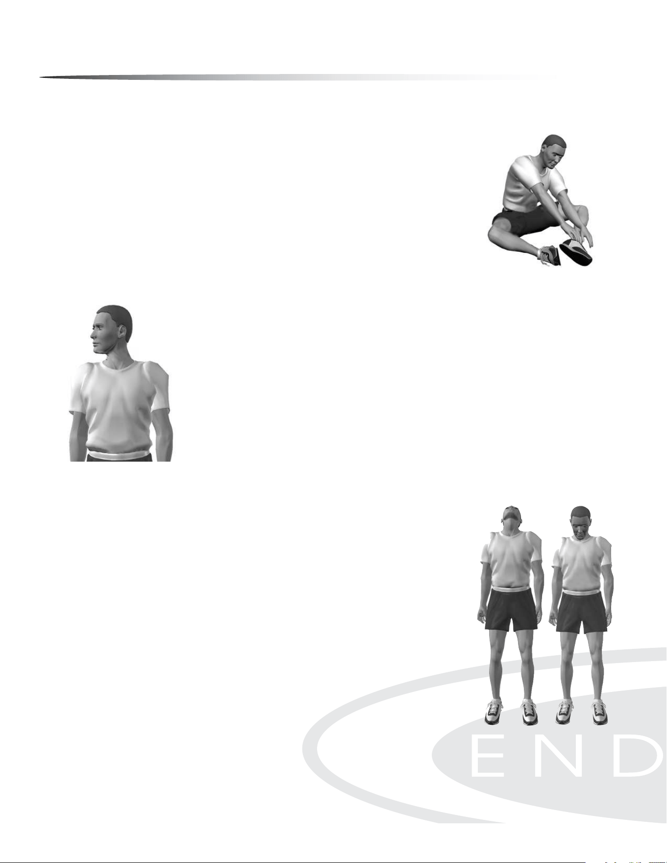
UPPER BACK
Cross Arm in Front of Chest
MUSCLE(S) AFFECTED: latissimus dorsi and teres major
Stand or sit with the right arm slightly exed (15° to 30°) and adducted across the chest.
Grasp the upper arm just above the elbow, placing the left hand on the posterior side of the
upper arm.
Pull the right arm across the chest (toward the left) with the left hand; hold for 10 seconds.
Repeat with the left arm.
1.
2.
3.
4.
Stretching the upper back
UPPER BACK
Arms Straight Up Above Head (Pillar)
MUSCLE(S) AFFECTED: latissimus dorsi and wrist exors
Stand with arms in front of torso, ngers interlocked with palms facing each other.
Slowly straighten the arms above the head with palms up.
Continue to reach upward with hands and arms.
While continuing to reach upward, slowly reach slightly backward; hold for 10 seconds.
1.
2.
3.
4.
Stretching the shoulders, chest
and upper back
LOWER BACK
Spinal Twist (Pretzel)
MUSCLE(S) AFFECTED: internal oblique, external oblique and spinal erectors
Sitting with legs straight and upper body nearly vertical, place right foot on left side of left
knee.
Place back of left elbow on right side of right knee, which is now bent.
Place right palm on oor 12 to 16 inches behind hips.
Push right knee to the left with left elbow while turning shoulders and head to the right as
far as possible. Try to look behind the back. Hold for 10 seconds.
Repeat with left leg.
1.
2.
3.
4.
5.
Warm Up/Cool down Exercises
41
Neck Extension Neck Flexion
LOWER BACK
Semi-Leg Straddle
MUSCLE(S) AFFECTED: spinal erectors
Sitting, knees exed 30 to 50 degrees, let the legs totally relax.
Point the knees outward; the lateral side of the knees may or may not touch the oor.
Lean forward from waist and reach forward with extended arms; hold position for 10 to 15
seconds.
Bending and relaxing legs decreases hamstring involvement and increases lower back
stretch.
1.
2.
3.
4.
Stretching the lower back from
a seated position
Rotational exion
of the neck
NECK
Look Right and Left
MUSCLE(S) AFFECTED: sternocleidomastoid
Stand or sit with head and neck upright.
Turn head to the right using a sub-maximal concentric contraction; hold for 10 seconds.
Turn head to the left using a sub-maximal concentric contraction; hold for 10 seconds.
1.
2.
3.
NECK
Flexion and Extension
MUSCLE(S) AFFECTED: sternocleidomastoid, suboccipitals and splenii
Standing or sitting with head and neck upright, ex neck anteriorly (forward) by tucking chin
in toward the chest; hold for 10 seconds.
If the chin touches the chest, try to touch lower on the chest with the chin.
Extend neck posteriorly (backward) by trying to touch the head to the trapezius; hold for 10
seconds.
1.
2.
3.
Warm Up/Cool down Exercises
42
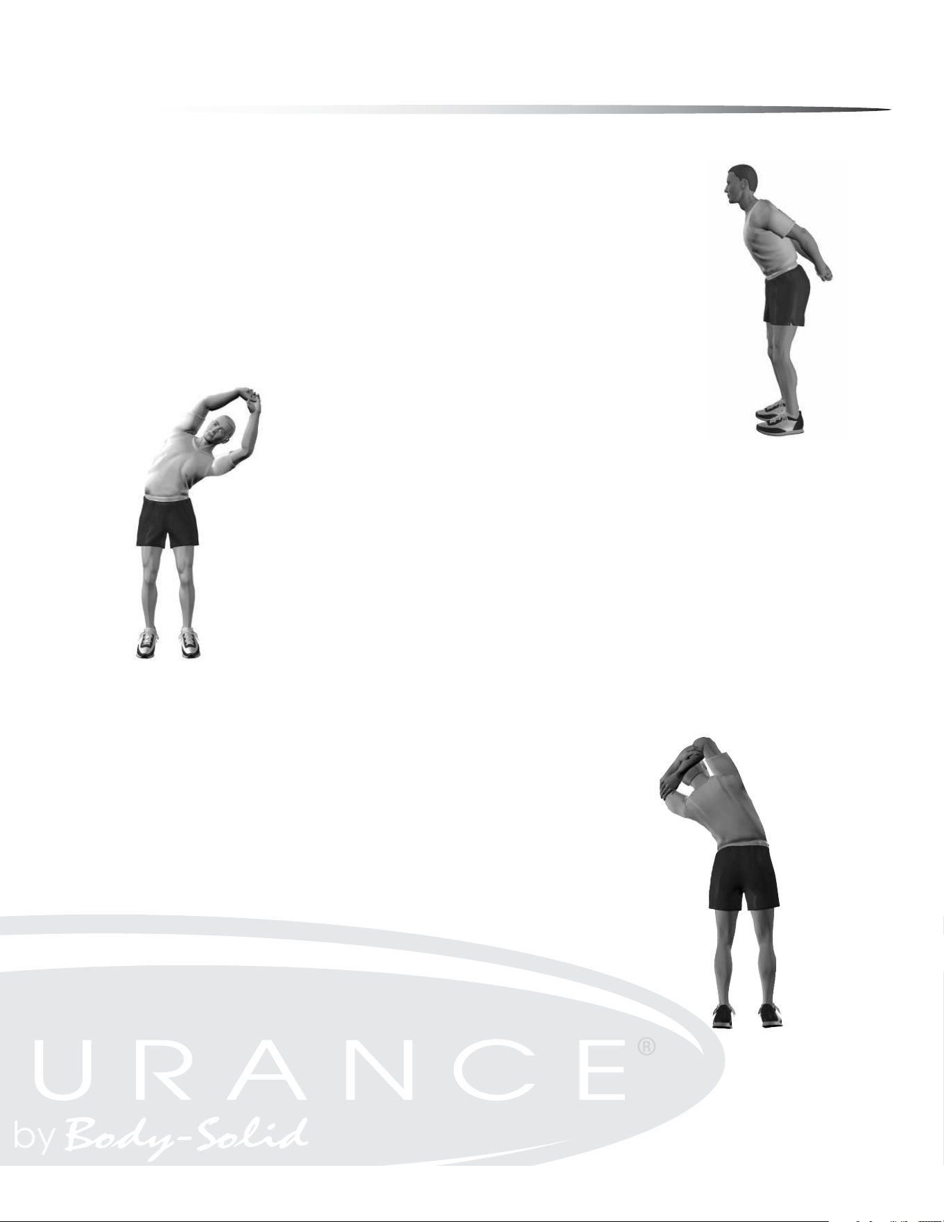
CHEST/SHOULDER
Straight Arms Behind Back
MUSCLE(S) AFFECTED: deltoids and pectoralis major
Standing, place both arms behind back.
Interlock ngers with palms facing each other.
Straighten arms fully.
Slowly raise the straight arms; hold for 10 to 15 seconds.
Keep head upright and neck relaxed.
1.
2.
3.
4.
5.
SIDES
Side Bend with Straight Arms
MUSCLE(S) AFFECTED: external oblique, latissimus dorsi and serratus anterior
Stand with feet 14 to 16 inches apart.
Interlace the ngers with palms facing each other.
Reach upward with straight arms.
Keeping arms straight, lean from waist to left side. Do not bend knees.
After moving as far as possible; hold for 10 seconds.
Repeat to the left side.
1.
2.
3.
4.
5.
6.
SIDES
Side Bend with Bent Arms
MUSCLE(S) AFFECTED: external oblique, latissimus dorsi , serratus anterior and triceps
Stand with feet 14 to 16 inches apart.
Flex right arm and raise elbow above head.
Reach the right hand down toward the left shoulder.
Grasp the right elbow (just above the elbow) with the left hand.
Pull the elbow behind head.
Keeping arm bent, lean from waist to left side.
Do not bend knees.
After moving as far as possible; hold for 10 to 15 seconds.
Repeat with the left arm.
1.
2.
3.
4.
5.
6.
7.
8.
9.
Stretching the sides, triceps
and upper back
Stretching the sides, upper
back and shoulders
Stretching shoulder joints and
chest while standing
Warm Up/Cool down Exercises
43
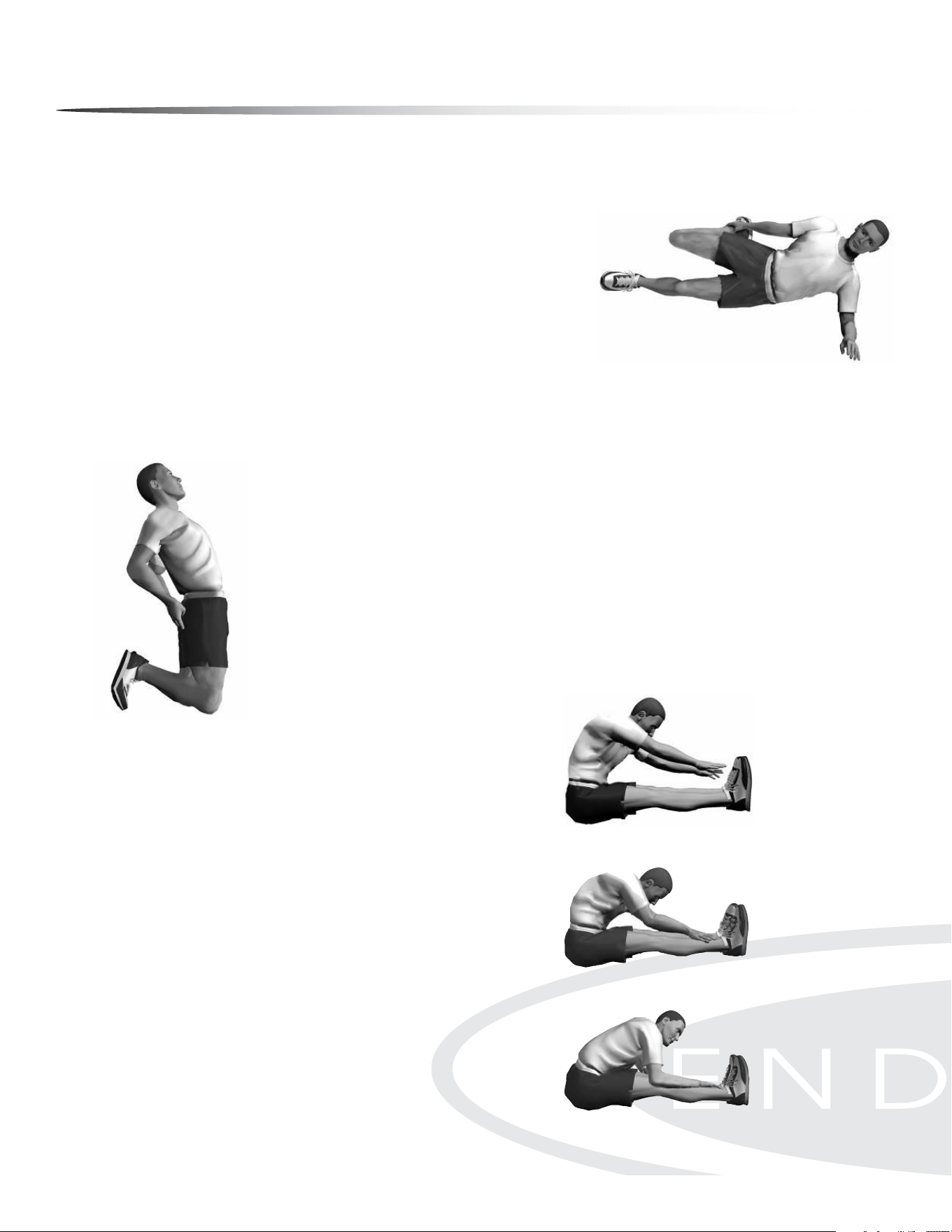
ANTERIOR OF THIGH AND HIP FLEXOR
Side Quadricep Stretch
MUSCLE(S) AFFECTED: quadriceps and iliopsoas
Lie on left side with both legs straight.
Place left forearm at on oor and upper arm perpendicular to oor.
Place left forearm at 45° angle with torso.
Flex right leg with heel of right foot moving toward buttocks.
Grasp front of ankle with right hand and pull toward buttocks.
WARNING: Do not pull on ankle so hard that pain or discomfort is felt in knee.
Move knee backward and slightly upward. The stretch occurs not so much from the excessive
exion of the knee but from moving the knee back and slightly up; hold for 10 to 15 seconds.
Repeat with the left leg.
1.
2.
3.
4.
5.
6.
7.
ANTERIOR OF THIGH AND HIP FLEXOR
Kneeling Quadriceps Stretch
MUSCLE(S) AFFECTED: quadriceps
Kneel with the balls of the feet on the ground.
Keep hips straight (upper leg and torso should be in a straight line).
Place palms of hands on buttocks and push slightly forward.
With a straight body, lean slightly backward until developmental stretch is felt in quadriceps;
hold for 10 to 15 seconds.
1.
2.
3.
4.
POSTERIOR OF THIGH
Sitting Toe Touch
MUSCLE(S) AFFECTED: hamstrings, spinal erectors and gastrocnemius
Sit with the upper body nearly vertical and legs straight.
Lean forward from waist and grasp toes with each hand, slightly pull
toes towards the upper body, and pull chest towards leg; hold for 10
seconds. (If you are very sti, try to grasp the ankles.)
Release toes and relax foot.
Grasp ankles and continue to pull chest towards legs; hold for 10
seconds.
Still grasping the ankles, point away from body and continue to pull
chest towards legs; hold for 10 seconds.
1.
2.
3.
4.
5.
Stretching the quadriceps
on side
Stretching the quadriceps
kneeling
Stretching the hamstrings
with emphasis on insertion of
the hamstrings and calves.
Stretching the hamstrings
with emphasis on the middle
portion.
Stretching the hamstrings
with emphasis on the
upper portion.
Warm Up/Cool down Exercises
44
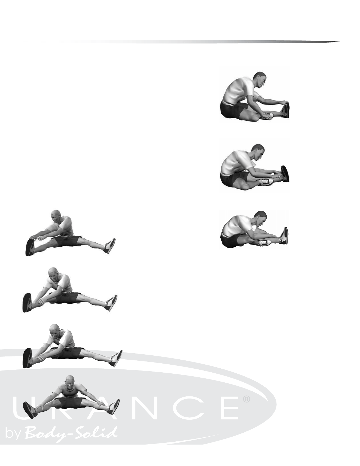
POSTERIOR OF THIGH
Semistraddle (Figure Four)
MUSCLE(S) AFFECTED: gastrocnemius, hamstrings and spinal erectors
Sit with the upper body nearly vertical and legs straight.
Place sole of left foot on left side of right knee. The lateral side of left leg
should be resting on the oor.
Lean forward from the waist and grasp toes with right hand and slightly pull
toes toward the upper body as the chest is also pulled toward right leg; hold
for 10 seconds.
Release toes and relax foot.
Grasp ankle and continue to pull chest toward right leg; hold for 10 seconds.
Point toes away from body and continue to pull chest toward right leg; hold
for 10 seconds.
Repeat with the left leg.
1.
2.
3.
4.
5.
6.
7.
GROIN
Straddle (Spread Eagle)
MUSCLE(S) AFFECTED: gastrocnemius, hamstrings, spinal erectors,
adductors and sartorius
Sit with the upper body nearly vertical and legs straight, and spread legs as
far as possible.
With right hand, grasp toes of right foot and pull on toes slightly, while pull-
ing chest toward right leg; hold for 10 seconds.
Release toes and relax foot.
Grasp ankle and continue to pull chest toward right leg; hold for 10 seconds.
Point toes away from body and continue to pull chest toward right leg; hold
for 10 seconds.
Repeat process with the left leg.
Repeat process by grasping right toes with right hand and left toes with left
hand. Move the torso forward and toward the ground.
1.
2.
3.
4.
5.
6.
7.
Stretching the hamstrings
with emphasis on insertion of
the hamstrings and calves
Stretching the hamstrings
with emphasis on the
middle portion
Stretching the hamstrings
with emphasis on the
upper portion
Stretching the hamstrings
and groin with emphasis on
insertion of the hamstrings
and calves
Stretching the hamstrings and
groin with emphasis on the
middle portion
Stretching the hamstrings and
groin with emphasis on the
upper portion
Stretching the groin, low
back and hamstrings
Warm Up/Cool down Exercises
45
Warm Up/Cool down Exercises
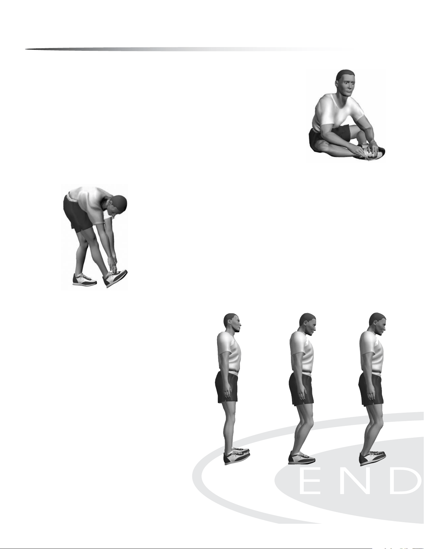
GROIN
Buttery
MUSCLE(S) AFFECTED: adductors and sartorius
Sitting with the upper body nearly vertical and legs straight, ex both knees as the soles of
the feet come together.
Pull feet toward body.
Place hands on feet and elbows on legs.
Pull torso slightly forward as elbows push legs down; hold for 10 to 15 seconds.
1.
2.
3.
4.
POSTERIOR OF LOWER LEG
Bent-Over Toe Raise
MUSCLE(S) AFFECTED: gastrocnemius and soleus
Stand with heel of right foot 6 to 8 inches in front of left foot.
Flex right foot toward shin (dorsi-exion) with heel in contact with oor.
Lean forward and try to touch right leg with chest while both legs are straight.
Continue to lean downward with upper body as the foot is dorsi-exed near maximal toward
the shin; hold for 10 to 15 seconds.
Repeat with the left leg.
1.
2.
3.
4.
5.
POSTERIOR OF LOWER LEG
Step Stretch
MUSCLE(S) AFFECTED: gastrocnemius and soleus;
also, achilles tendon
Have ready a step or board 3 to 4 inches high.
Place balls of both feet on the step or board, 1 inch from
its edge.
With straight legs, lower heels as far as possible; hold for
10 to 15 seconds.
To stretch achilles tendon, raise heels slightly. Slightly ex
the knees and then lower the heels. This stretch will be
felt in the achilles tendon; hold for 10 to 15 seconds.
For a more intense and individualized stretch, perform
this stretch with one leg at a time.
1.
2.
3.
4.
5.
Stretching the calves
standing on a step
Preparing to stretch
the achilles tendon by
slightly bending the knee
Stretching the
achilles tendon by
lowering the heel
Stretching the groin
Stretching calves without a
step
46
Warm Up/Cool down Exercises
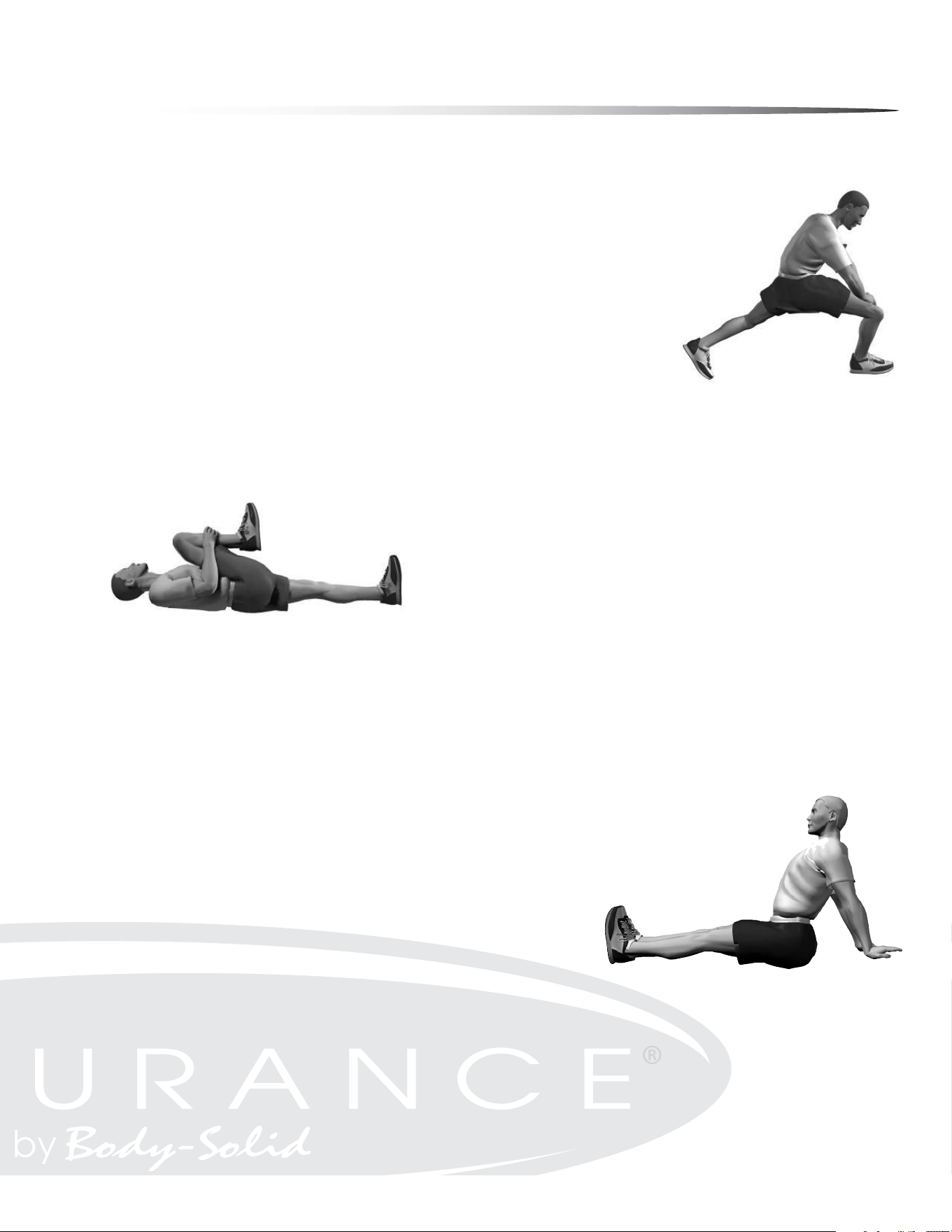
HIPS
Forward Lunge (Fencer)
MUSCLE(S) AFFECTED: iliopsoas, rectus femoris
1. Standing, take a long step forward (as with the lunge) with the right leg and ex the right
knee until it is directly over the right foot.
Keep right foot at on oor.
Keep back leg straight.
Keep back foot pointed in same direction as front foot; it is not necessary to have heel on oor.
Keep torso upright and rest hands on hips or front leg.
Slowly lower hips forward and downward; hold for 10 to 15 seconds.
Repeat with the left leg.
1.
2.
3.
4.
5.
6.
7.
HIPS
Supine Knee Flex
MUSCLE(S) AFFECTED: hip extensors (gluteus maximus and hamstrings)
Lie on back with legs straight.
Flex right leg and lift knee toward chest.
Place both hands below knee and continue to pull knee toward chest; hold for
10 to 15 seconds.
Repeat with left leg.
1.
2.
3.
4.
SHOULDER
Seated Lean-Back
MUSCLE(S) AFFECTED: deltoids and pectoralis major
Sitting with legs straight and arms extended, place palms on oor about 12 inches behind
hips.
Point ngers away (backward) from body.
Slide hands backward and lean backward; hold for 10 seconds.
1.
2.
3.
Stretching shoulder
joints—sitting
Stretching the hip exors
Stretching the gluteals
and hamstrings
47
Maintenance
Your Endurance
®
E5000 Elliptical has been manufactured to withstand many hours of use
with minimal maintenance. Here are some maintenance tips to keep your Endurance
®
E5000
Elliptical running at its best.
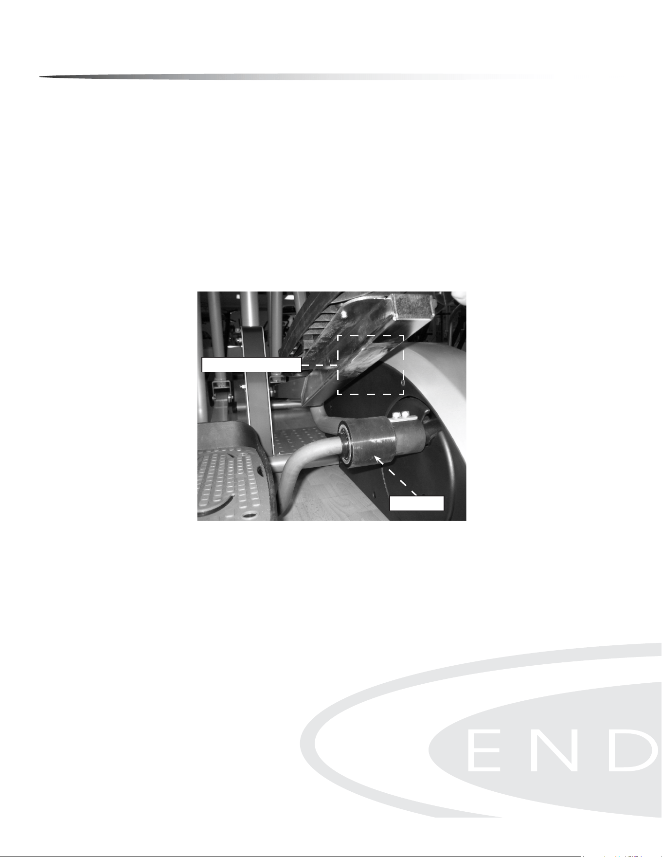
IF SQUEAKING NOISE OCCURS
Your Endurance
®
E5000 Elliptical may occasionally require Multi-Purpose Grease to be ap-
plied onto the underside of the foot pedal tube as shown. A small tube of Multi-Purpose
Grease was included with your unit and can also be purchased at most stores. DO NOT USE
WD-40 OR SILICON SPRAY since these compounds will increase squeaking noise over time.
Apply the Multi-Purpose Grease onto the bottom of both foot pedal tubes in the area that
makes contact with the roller wheel as shown below. During normal usage (30 minutes of
exercise per day), Multi-Purpose Grease is to be applied every 3 months or as needed.
CLEANING
Periodically wipe down your machine with mild, soapy water or a diluted general purpose
non-abrasive household cleaner. Cleaner should never be applied directly to any part of the
equipment. Instead, place the non-abrasive cleaning solution on a soft cloth and wipe down
the unit. The elliptical should be wiped down to remove sweat after each use.
ERROR MESSAGES
The E5000 console is equipped with auto-diagnostic technology if any fault to the machine
is to occur in order to protect the safety of the user and the integrity and reliability of the
machine. The E5000 console automatically checks the brake motor status every time the unit
is powered on. If the brake motor does not reply to the console’s diagnostic call or does not
move to its target position within 2 seconds, the console will display the error message ‘MO-
TOR ERROR’ immediately and disable button operation until power is reset. To clear the error
message, unplug then plug in the unit.
If the console still displays the error message ‘MOTOR ERROR’, contact an authorized Endur-
ance
®
dealer or an Endurance
®
factory-authorized service company or contact Endurance
®
Customer Tech Support at 1-800-556-3113
.
Apply grease to this area
Roller Wheel
Correct Grease Application
Apply grease to this area
Roller Wheel
48

Troubleshooting Guide
Symptom
Possible Cause
Solution
DC adapter is not plugged
into wall outlet?
Plug DC adapter into wall outlet.
DC adapter is not plugged into the Plug DC adapter into the E5000 power socket.
Console cable is not connected? Verify that the console cable is connected properly.
The console is faulty?
Call the Endurance
®
service number.
Check that the sensor magnet is correctly
tted and passes in front of the sensor.
Check that the gap between the sensor
and the magnet is 3mm or less.
Check that all the computer plugs and sockets
are correctly and rmly connected.
If all above checks are O.K., then replace sensor.
Call the Endurance
®
service number.
Check that the pulse plugs rmly
inserted into the sockets.
Check to make sure that the batteries in
the chest strap are installed correctly.
Replace the chest strap batteries.
Check to see if the receiver is properly installed.
Check to see if the chest strap is being properly worn by
the user - if skin is extremely dry, then moisten contact
points on chest with water and try again.
If the problem still exists then call the
Endurance
®
service number.
Try reversing the resistance and try again.
If this fails, then replace the motor.
Console has no power.
Strides/Min
or Speed shows 0
No HR signal
or incorrect HR signal
Noise from motor
Computer isn’t receiving a
signal from the sensor?
The sensor is faulty?
The computer is faulty?
Computer is receiving a faint or
intermittent pulse signal.
Symptoms include an unusually loud
noise coming from the motor,
which means the gears are
not meshing correctly.
Any Questions?
Call the Customer Tech Hotline at:
1 (800) 556-3113
49
Reference drawings
50
Reference drawings
51
Customer Tech Support Hotline
Toll Free: 1-800-556-3113
Phone: 1-708-427-3555
Fax: 1-708-427-3556
Hours: M-F 8:30-5:00 CST
E-Mail: service@bodysolid.com
Serial Number is Located on the Frame
Model Name
:
E 5000
Purchase Date
: _______________________________
Serial Number
: _______________________________