This product is intended for indoor, home use only and is not to be used in a commercial setting.
BR2998
ELLIPTICAL TRAINER
BR2998 Page 1
PLEASE KEEP THESE INSTRUCTIONS FOR FUTURE USE & REFERENCE.
DO NOT DISCARD.
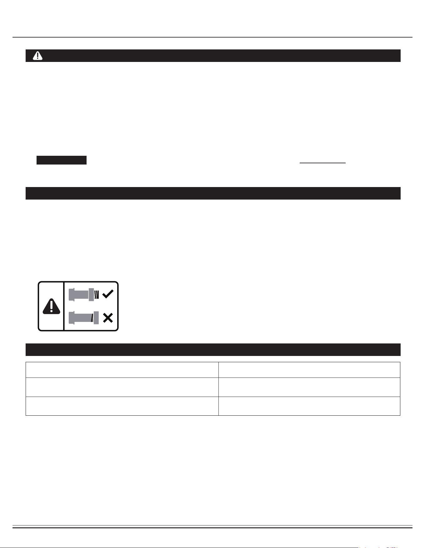
WARNING: SERIOUS INJURIES AND EVEN DEATH CAN OCCUR IF THE PROPER SAFETY PRECAUTIONS
ARE NOT FOLLOWED.
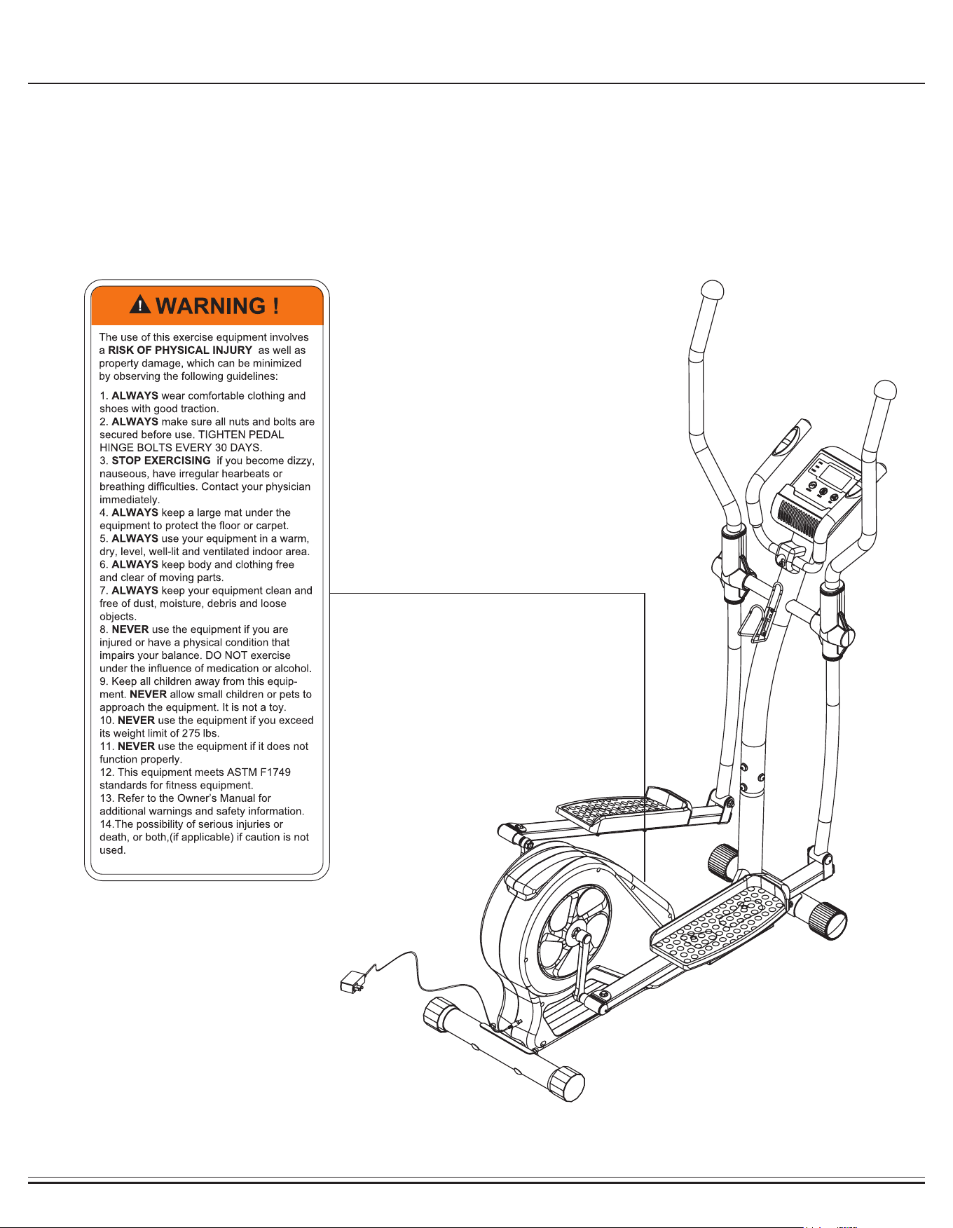
The diagram below highlights and reviews many of the important Safety and Warning labels also found on the unit.
Please ensure any user of the unit familiarizes themselves with these Safety and Warning guidelines before use.

BR2998 Page 2
Before you undertake any exercise program, please be sure to
consult with your doctor.
Frequent strenuous exercise should be approved by your
doctor and proper use of your product is essential.
Excessive or incorrect training may result to health injuries.
Please read this manual carefully before commencing the
assembly of your product or starting to exercise.
• Please keep all children away from this item when in use.
Do not allow children to climb or play on this item when it
is not in use.
• Supervise teenagers while they use this unit.
• For your own safety, always ensure that there is at least
3 feet of free space in all directions around your product
while you are exercising.
• Regularly check to see that all nuts, bolts and ttings are
securely tightened. Periodically check all moving parts for
obvious signs of wear or damage.
• Any adjustment devices that could interfere with the user’s
movement on this unit should not be left projecting.
• Clean only with a damp cloth, do not use solvent
cleaners. Lubricate the moving parts of your unit every 30
days with a silicone-based grease or product.
If you are in any doubt, do not use your product; contact
CUSTOMER SUPPORT.
• Before use, always ensure that your product is positioned
on a solid, hard-at surface.
• Do not place on carpet. If necessary, use a rubber mat
underneath to reduce the possibility of slipping.
• Always wear appropriate clothing and footwear such as
training shoes when exercising. Do not wear loose clothing
that could become caught in moving parts during exercise.
• Do not use this unit if it is not functioning properly or if it is
not fully assembled.
• Do not use this unit for commercial purposes. This unit is
for home use only.
• Before use, you must read and understand all instructions
& warnings stated in this Owner’s Manual as well as post-
ed on the equipment.
• It is the facility owner’s responsibility to properly instruct
users on the proper operation of the equipment and to
warn them of the potential hazards.
• If at any time during exercise you feel faint, dizzy or
experience pain, stop and consult your physician.
Your product is intended for use in clean dry conditions. You
should avoid storage in excessively cold or damp places as
this may lead to corrosion and other related problems.
If you have any questions concerning the assembly of your
item or if any parts are missing, please DO NOT RETURN
THE ITEM TO THE STORE OR CONTACT THE
RETAILER.
Our dedicated customer service staff can help you with
any questions you may have regarding the assembly of this
unit and can also mail you replacement parts.
Customer Support is open 9:00 a.m. to 5:00 p.m. (Pacic
Time) Monday through Friday.
Please contact us by any of the following means :
Body Flex Sports, Inc.
21717 Ferrero Parkway, Walnut, CA 91789
Telephone: 1 (888) 266 - 6789
Fax: 1 (909) 598 - 6707
Email: info@bodyexsports.com
Body Flex Sports warrants your product for a period of
1 year for the frame and 90 days on all parts if the item is used
for the intended purpose, properly maintained and not used
commercially.
Any alterations or incorrect assembly of the product will void
this warranty.
Proof of purchase must be presented for any warranty
validation (no exceptions). This warranty applies to the original
purchaser only and is not transferable.
This warranty does not cover abuse or defects caused during
use, storage or assembly. During the warranty period, Body
Flex Sports reserves the right to:
1. provide replacement parts to the purchaser in an effort to
repair the item.
2. repair the product returned to our warehouse (at the
purchaser’s cost).
3. replace the product if neither of the two previously
mentioned actions effect repair. This warranty does not
cover normal wear and tear on upholstery.
- Ruler with both Metric and English measurements
- 2 x Adjustable Wrenches
- 1 x Philips (”Crosshead”) Screw Driver
General Information
Safety Storage and Use
Questions
Customer Support
Warranty
Assembling Tools
Weight Limit
Your product is suitable for users weighing:
275 pounds or less
BR2998 Page 3
Before Assembly
1. Take a few minutes to familiarize yourself with the parts and hardware included with your product.
2. Assembly may require two people.
3. Check the frame for any damage and check any wiring (if present) for rips or tears. If you detect damage, rips, or
tears, please contact our Customer Support Team before beginning any assembly.
4. Make sure all the hardware needed is included.
5. It is very important to follow the assembly instructions correctly and to make sure all parts are attached correctly and
rmly tightened when the assembly process is complete.
6. Parts that are not tightened correctly will seem loose and can cause irritating noises and will cause damage to the
equipment.
1. It is only necessary to tighten the bolts and nuts to “nger tight” during the assembly process. This will make it
easier to complete certain steps by allowing more tolerance for all the parts to t properly.
2. Do not tighten all the nuts onto the bolts securely until after you have completed assembly of your product.
3. Use wrenches, pliers, or ratchet and sockets to tighten the bolts and nuts.
4. The Nylon Nut should thread onto the Hex Bolt until the end of the Hex Bolt has passed through the Nylon insert
inside the Nut. Please follow this guideline everytime you see this Nylon Nut icon throughout the assembly steps.
Nylon Lock Safety Nuts
Tools Required For Assembly
WARNING
PLEASE NOTE : Many of the parts and hardwares listed on the parts list are already pre-assembled or
installed on the unit.
Tool Description/Purpose
Ruler (with both Metric and English measurements)
QTY: 1
Use to measure the length or size of hardware including
bolts to ensure you are using the correct part.
Adjustable or at wrenches
QTY: 2
Use to securely install parts including nuts and bolts.

BR2998 Page 4
Part Listing
The following parts list describes all of the parts illustrated on the exploded diagram on the following page.
PLEASE NOTE : most of these parts are already pre-assembled on your unit.
# Description
01 Main Frame
02 Center Post
03 Left Pedal Tube
04 Right Pedal Tube
05 Left Coupler Bar
06 Right Coupler Bar
07 Pedal Connection Joint
08 Pulse Handle Bar
09 Left Handle Bar
10 Right Handle Bar
11 Front Stabilizer
12 Rear Stabilizer
13 Coupler Bar Axle
14 Crank
15 Bushing
16 Carriage Bolt (M8x70 mm)
17 Pedal Hinge Bolt (φ16x1/2"x97 mm)
18 Bolt (M10x68 mm)
19 Bolt (M8x40 mm)
20 Bolt (M8x20 mm)
21 Bolt (M8x15 mm)
22 Bolt (M8x30 mm)
23 Hex Bolt (M8x45 mm)
24 Hex Bolt (M8x40 mm)
25 Screw (M5x15 mm)
26 Screw (M5x12 mm)
27 Screw (M4x25 mm)
28 Screw (M4x10 mm)
29 Washer (M10)
30 Big Washer (M8)
31 Washer (M8)
# Description
32 Arc Washer (M8)
33 Spring Washer (M8)
34 Wavy Washer (φ16 mm)
35 Wavy Washer (φ19 mm)
36 Nylon Nut (1/2")
37 Nylon Nut (M10)
38 Nylon Nut (M8)
39 Cap Nut (M8)
40 Left Pedal
41 Right Pedal
42 Pulse Handle Bar Cover
43 Left Coupler Bar Cover (Rear)
44 Left Coupler Bar Cover (Front)
45 Right Coupler Bar Cover (Rear)
46 Right Coupler Bar Cover (Front)
47 Rectangular End Cap (25x50 mm)
48 Round End Cap (22 mm)
49 Round End Cap (32 mm)
50 Nylon Bushing (25 mm)
51 Nylon Bushing (32 mm)
52 End Cap for Front Stabilizer
53 End Cap for Rear Stabilizer
54 Foam Grip of Pulse Handle Bar
55 Foam Grip of Handle Bar
56 Monitor
57 Pulse Sensor
58 Monitor Wire (Upper)
59 Monitor Wire (Lower)
60 Adapter
61 Water Bottle Holder
62 Tool 1
63 Tool 2
BR2998 Page 5
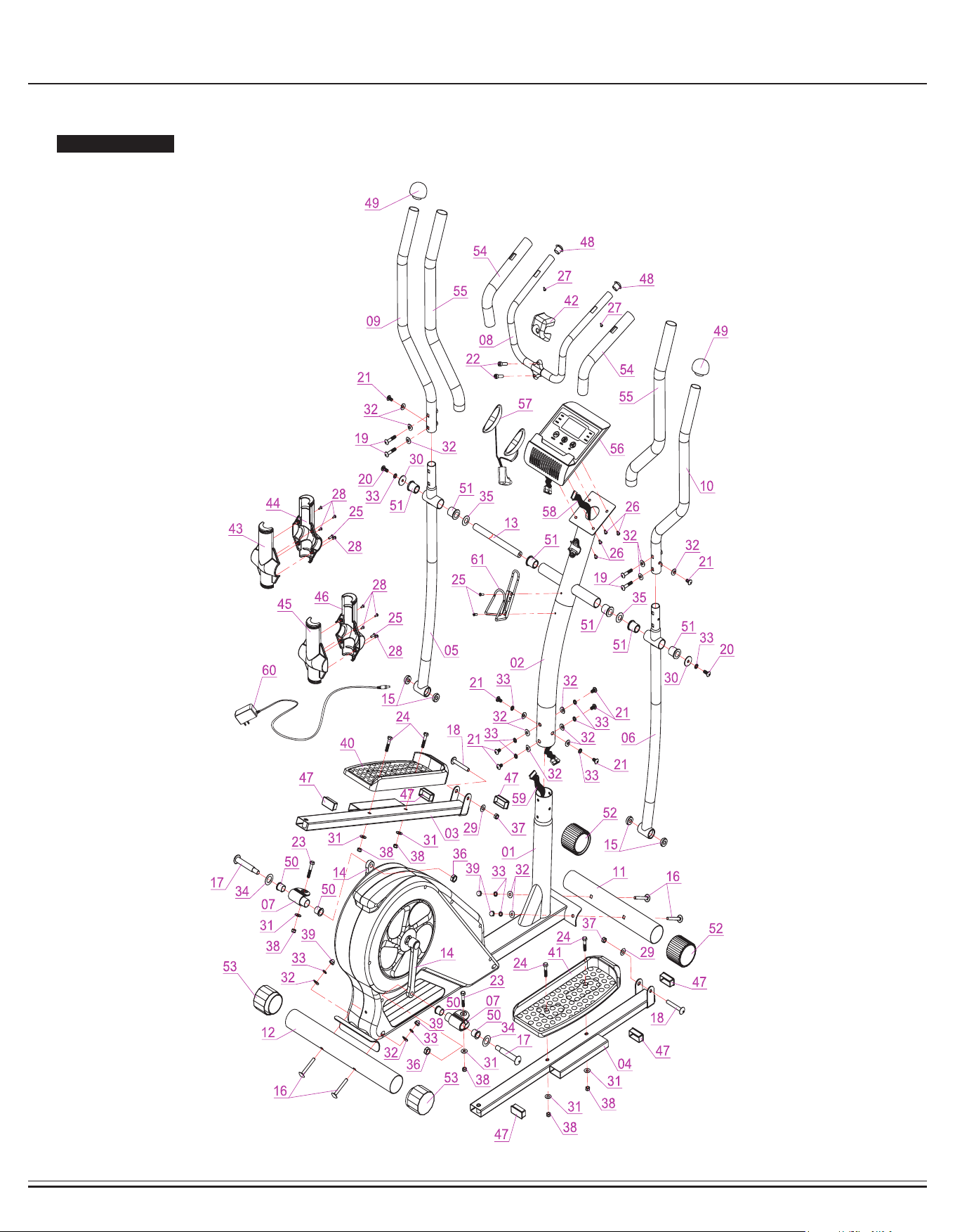
Exploded View
The following diagram is provided to help you familiarize yourself with the parts and hardware that will be used during the
assembly process.
: : Not all of the parts and hardware you see here will be used while you are assembling the machine
because some of these items are already pre-installed. Please use this page only as a reference guide for parts and
hardware.
PLEASE NOTE
BR2998 Page 6
#16. Carriage Bolt (M8x70 mm)
[4 pieces]
#19.Bolt (M8x40 mm)
[4 pieces]
#22.Bolt (M8x30 mm)
[2 pieces]
#24.Hex Bolt (M8x40 mm)
[4 pieces]
#25.Screw (M5x15 mm)
[4 pieces]
#28.Screw (M4x10 mm)
[8 pieces]
#17. Pedal Hinge Bol
t (φ16x1/2"x97 mm)
[2 pieces]
#20.Bolt (M8x20 mm)
[2 pieces]
#32.Arc Washer (M8)
[16 pieces]
[6 pieces pre-assembled]
#33.Spring Washer (M8)
[12 pieces]
[6 pieces pre-assembled]
#18.Bolt (M10x68 mm)
[2 pieces]
#21.Bolt (M8x15 mm)
[8 pieces]
[6 pieces pre-assembled]
#26. Screw (M5x12 mm)
[4 pieces pre-assembled]
#29.Washer (M10)
[2 pieces]
#34.Wavy Washer (φ16 mm)
[2 pieces]
#35.Wavy Washer (φ19 mm)
[2 pieces]
#31.Washer (M8)
[4 pieces]
#30.Big Washer (M8)
[2 pieces]
#36.Nylon Nut (1/2")
[2 pieces]
#37.Nylon Nut (M10)
[2 pieces]
#38.Nylon Nut (M8)
[4 pieces]
#39.Cap Nut (M8)
[4 pieces]
#63.Tool 2
[2 pieces]
#62.Tool 1
[2 pieces]
[pre-assembled]
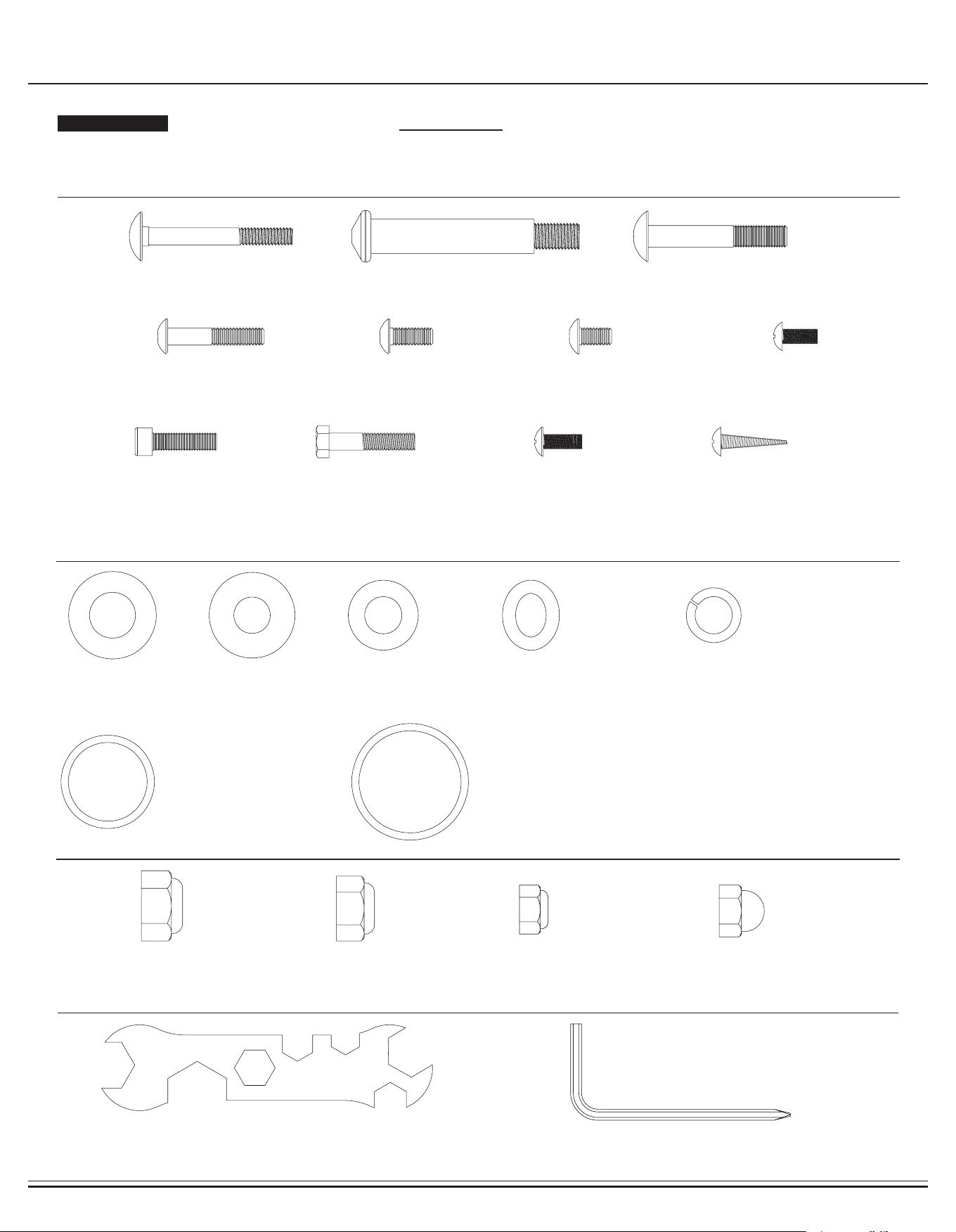
Hardware and Tool List
Bolts & Screws
Washers
Nuts
Tools & Others
The following hardware is used to assemble your unit. Please take a moment to familiarize yourself with these items.
PLEASE NOTE : Most of these parts are already pre-assembled on your unit. Do not be alarmed if you see parts on this
page that are not included in your hardware packet.
BR2998 Page 7
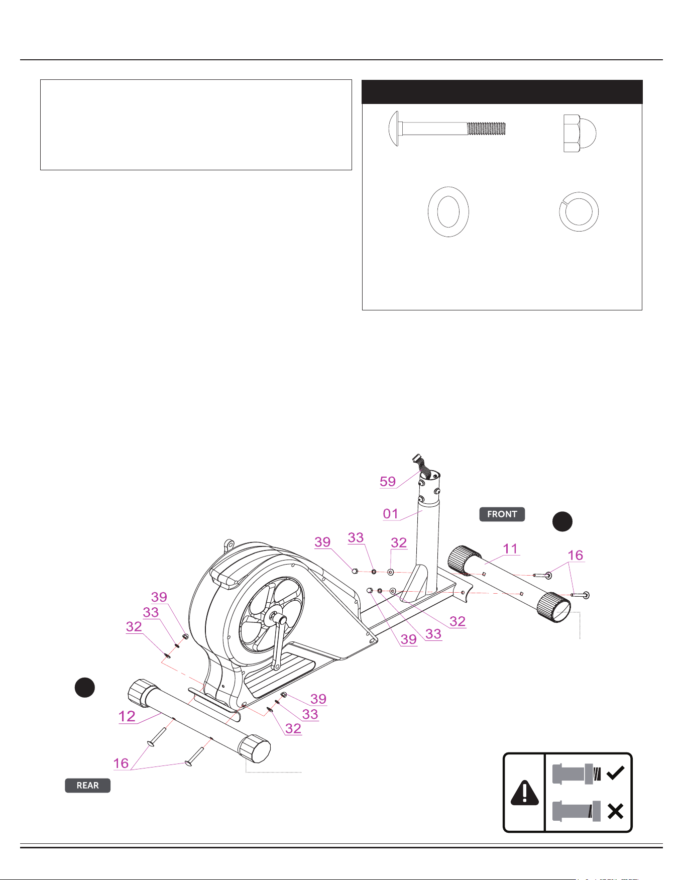
Assembly STEP 1
NOTE BEFORE STARTING THE ASSEMBLY PROCESS :
To avoid misalignment due to over-tightening, please do not use a
wrench and use only hand-tightening for now to ensure
easy assembly.
Wrench-tightening should be performed after all parts are assembled
to ensure all nuts, bolts, and parts are tightly secured before use.
A.) With the help of an assistant, attach the Front Stabilizer (#11)
to the front bracket of the Main Frame (#01). Insert two Carriage
Bolts(#16) through the Front Stabilizer (#11) followed by the front
bracket of the Main Frame (#01). Secure them together using two Arc
Washers (#32) two Spring Washers (#33) and two Cap Nuts (#39).
B.) Attach the Rear Stabilizer (#12) to the rear bracket of the Main
Frame (#01). Insert two Carriage Bolts(#16) through the
Rear Stabilizer (#12) followed by the rear bracket of the
Main Frame (#01).
Secure them together using two Arc Washers (#32) two Spring
Washers (#33) and two Cap Nuts (#39).
Please note that the Front Stabilizer (#11) has end caps that spin
for ease of relocating the unit. The Rear Stabilizer (#12) has height
adjustable end caps for leveling of the unit.
Hardware Required
A
B
Spinning End Caps
Height Adjustable
End Caps
#16. Carriage Bolt (M8x70 mm)
[4 pieces]
#32.Arc Washer (M8)
[4 pieces]
#33.Spring Washer (M8)
[4 pieces]
#39.Cap Nut (M8)
[4 pieces]
BR2998 Page 8
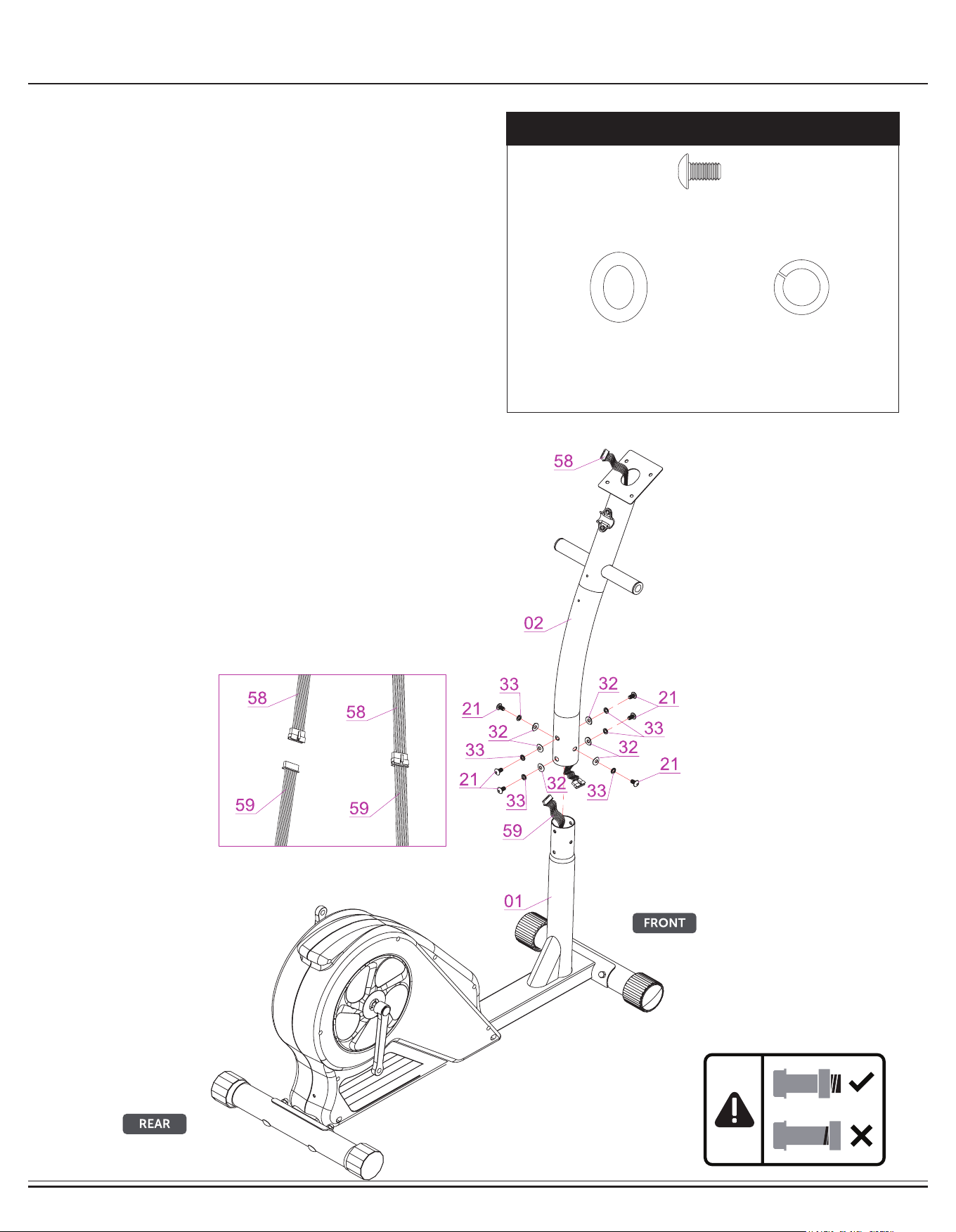
Assembly STEP 2
Remove the pre-assembled parts from the Main Frame (#01) and set
them aside: six Bolts (#21), six Spring Washers (#33) and six Arc
Washers (#32). With the help of an assistant, connect the Monitor
Wire (Upper) (#58) to Monitor Wire (Lower) (#59) as shown in detail
diagram below.
Attach the Center Post (#02) to the Main Frame (#01) and secure
using six Bolts (#21), six Spring Washers (#33) and six Arc Wash-
ers (#32) that were previously removed.
Hardware Required
#32.Arc Washer (M8)
[6 pieces]
#33.Spring Washer (M8)
[6 pieces]
#21.Bolt (M8x15 mm)
[6 pieces]
BR2998 Page 9
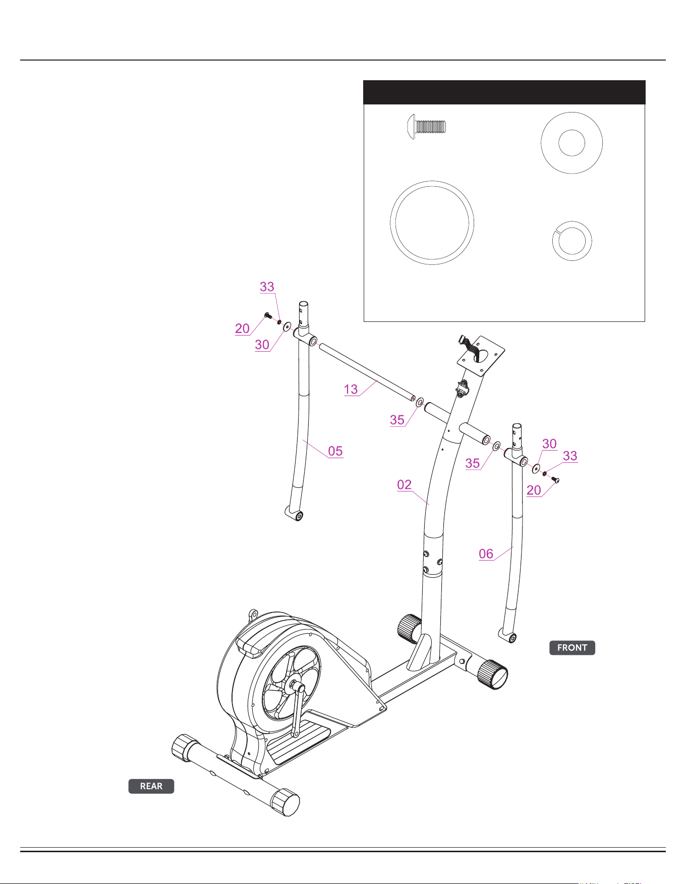
Assembly STEP 3
Slide the Coupler Bar Axle (#13) through the center slot on the
Center Post (#02) and center it so it is evenly distributed on the left/
right sides.
Next, slide one Wavy Washer (#35) on each side then, followed by
corresponding Left/Right Coupler Bar (#05/#06). Secure each side
with a Big Washer (#30), a Spring Washer (#33) and a Bolt (#20).
Hardware Required
#20.Bolt (M8x20 mm)
[2 pieces]
#33.Spring Washer (M8)
[2 pieces]
#35.Wavy Washer (φ19 mm)
[2 pieces]
#30.Big Washer (M8)
[2 pieces]
BR2998 Page 10
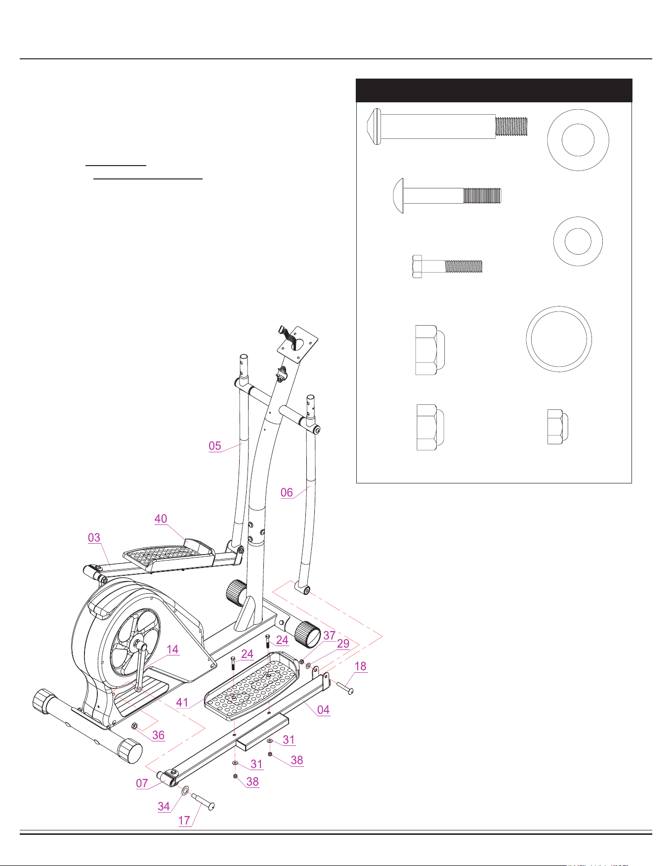
Assembly STEP 4
Align and attach the Pedal Connection Joint (#07) on the Right
Pedal Tube (#04) to the right Crank (#14). Insert a Pedal Hinge
Bolt (#17) through a Wavy Washer (#34) followed by Pedal Con-
nection Joint (#07) and Right Crank (#14).
Screw the Pedal Hinge Bolt (#17) tightly into the Right Crank (#14)
by turning CLOCKWISE and then secure it with the Nylon Nut (#36)
by turning it COUNTERCLOCKWISE.
Align and attach the Right Coupler Bar (#06) to the Right Pedal
Tube (#04). Secure them together using a Bolt (#18), Washer (#29)
and a Nylon Nut (#37).
Attach the Right Pedal (#41) to the Right Pedal Tube (#04) and se-
cure them together using two Hex Bolts (#24), two Washers (#31)
and two Nylon Nuts (#38).
Repeat this process on the other side with the Left Pedal Tube (#03)
and Left Coupler Bar (#05).
Hardware Required
#24.Hex Bolt (M8x40 mm)
[4 pieces]
#17. Pedal Hinge Bolt (φ16x1/2"x97 mm)
[2 pieces]
#18.Bolt (M10x68 mm)
[2 pieces]
#29.Washer (M10)
[2 pieces]
#34.Wavy Washer (φ16 mm)
[2 pieces]
#31.Washer (M8)
[4 pieces]
#36.Nylon Nut (1/2")
[2 pieces]
#37.Nylon Nut (M10)
[2 pieces]
#38.Nylon Nut (M8)
[4 pieces]
BR2998 Page 11
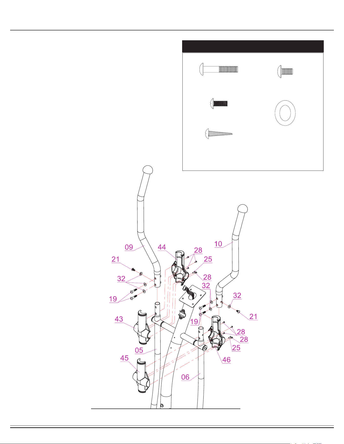
Assembly STEP 5
Insert the Left Handle Bar (#09) into the opening at the top of the
Left Coupler Bar (#05) and secure it using two Bolts (#19), two Arc
Washers (#32) from the REAR, and one Bolt (#21),
one Arc Washers (#32) from the side.
Attach Left Coupler Bar Cover (Rear) (#43) and Left Coupler Bar
Cover (Front) (#44) to the Left Handle Bar (#09). Secure them
together by using four Screws (#28) and one Screw (#25).
Repeat this process on the other side with the Right Handle Bar
(#10), Right Coupler Bar(#06), Right Coupler Bar Cover (Rear)
(#45) and Right Coupler Bar Cover (Front) (#46).
Remove the pre-assembled Screws (#28) from the Left Coupler Bar
Cover (Rear) (#43), Left Coupler Bar Cover (Front) (#44), Right
Coupler Bar Cover (Rear) (#45) and Right Coupler Bar Cover
(Front) (#46).
Hardware Required
#19.Bolt (M8x40 mm)
[4 pieces]
#25.Screw (M5x15 mm)
[2 pieces]
#28.Screw (M4x10 mm)
[8 pieces]
#32.Arc Washer (M8)
[6 pieces]
#21.Bolt (M8x15 mm)
[2 pieces]
BR2998 Page 12
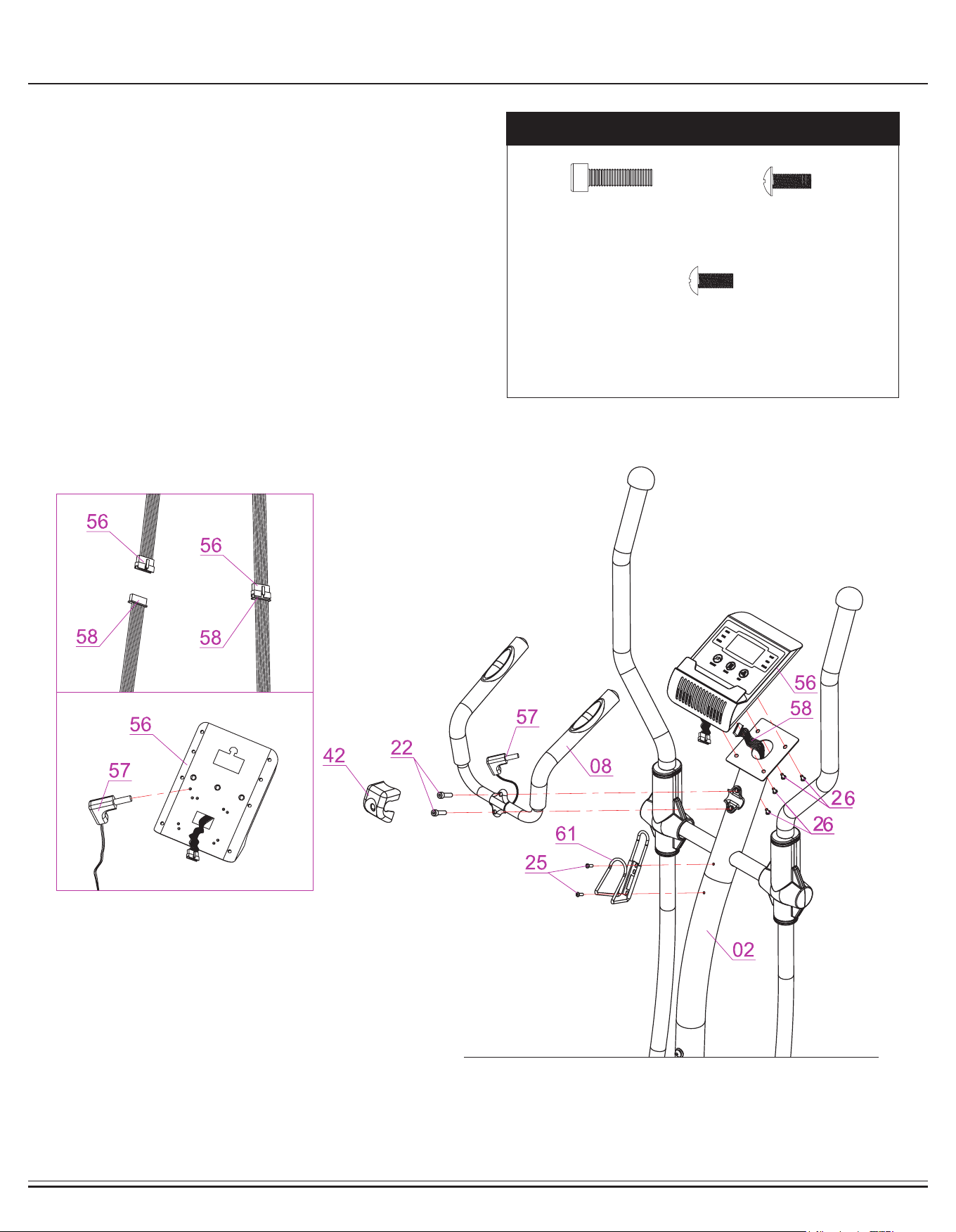
Assembly STEP 5
Align and attach the Pulse Handle Bar (#08) to the bracket on the
Center Post (#02), secure them together by using two Bolts (#22).
Clip the Pulse Handle Bar Cover (#42) onto the Center of the Pulse
Handle Bar (#08).
Remove the Screws (#26) that are pre-assembled on back of the
Monitor (#56) and set them aside as they will be used shortly in this
step.
Connect the Monitor Wire (Upper) (#58) to the Wire on the Monitor
(#56) and connect the Pulse Sensor Wire (#57) to the back of the
Monitor (#56).
Secure the Monitor (#56) to the bracket of the Center Post (#02) by
using four Screws (#26) that were previously removed.
Attach the Water Bottle Holder (#61) to the Center Post (#02),
secure them together by using two Screws (#25).
Hardware Required
Note:
HAND PULSE SIGNAL
After assembly is completed, if the computer is not picking up your
hand pulse signal (or you are getting inaccurate readings), please refer
to our “Troubleshooting” section to resolve the issue.
#22.Bolt (M8x30 mm)
[2 pieces]
#25.Screw (M5x15 mm)
[2 pieces]
#26. Screw (M5x12 mm)
[4 pieces]
BR2998 Page 13
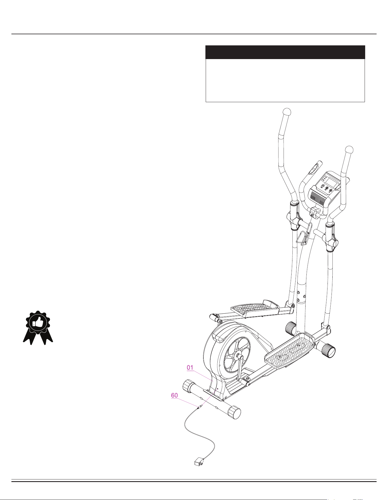
Assembly STEP 5
Plug in the AC Adapter (#60) male plug into the female socket
located at the rear of the unit as shown below.
No hardware required
Hardware Required
THE ASSEMBLY PROCESS IS NOW COMPLETE.
However, for your own safety, please make sure
to read this entire Owner’s Manual which includes
safety instructions and warnings, as well as any
safety/warning labels afxed to the product before
use. For your safety, please visually and functionally
inspect and test the unit after assembly is complete.
BR2998 Page 14
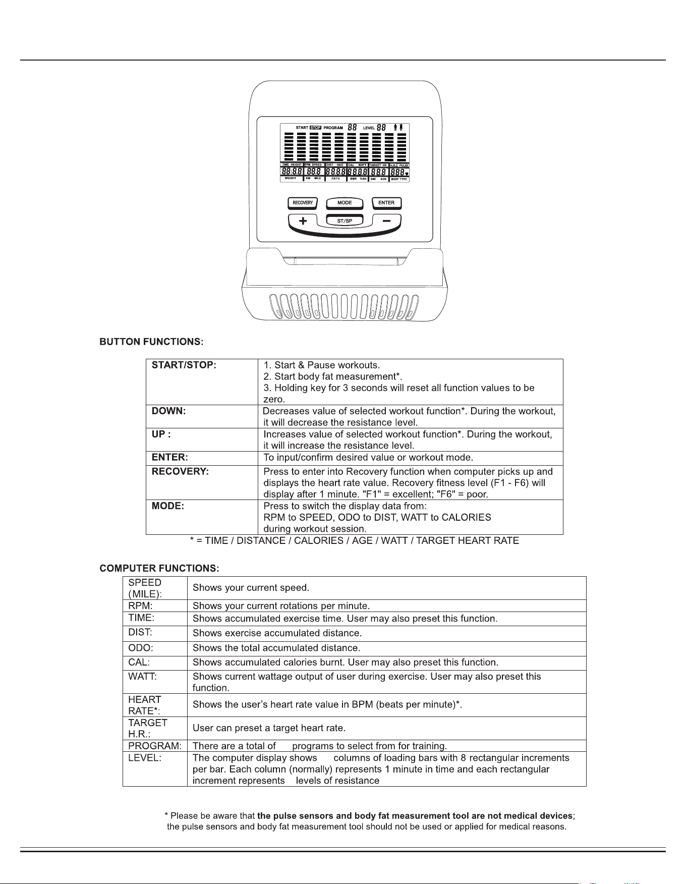
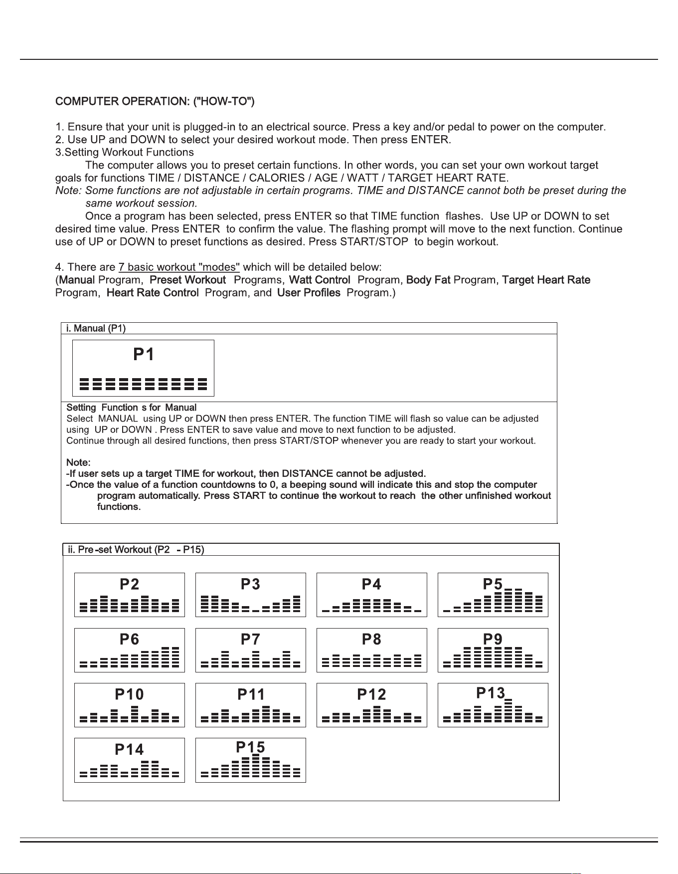
Computer Operation
26
10
3
for a total of 24 resistance levels.
BR2998
Page 15
Computer Operation
BR2998
Page 16
Computer Operation
14
BR2998
Page 17
Computer Operation
BR2998
Page 18
Computer Operation
RESISTANCE LEVEL
There are 24 level units that you can set to achieve the desired resistance level to create your own training
program. Press UP, DOWN buttons to adjust resistance level of the first profile unit. Each bar represents 3 resistance
level (3 x 8 bars = 24 levels). The resistance level is also display on the top right on the screen.
During adjustment, you will see the display changes when you press UP or DOWN buttons twice.
Press MODE button to move to the next profile unit. Then, use UP and DOWN buttons again to set the desired
resistance level until you've completed program profile.
You may also adjust resistance during training. Note that the computer will save the last program set for each user.
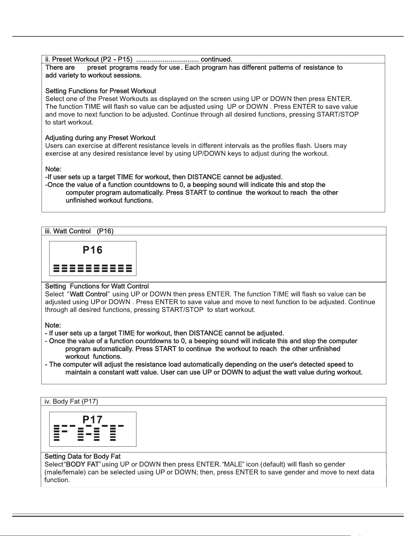
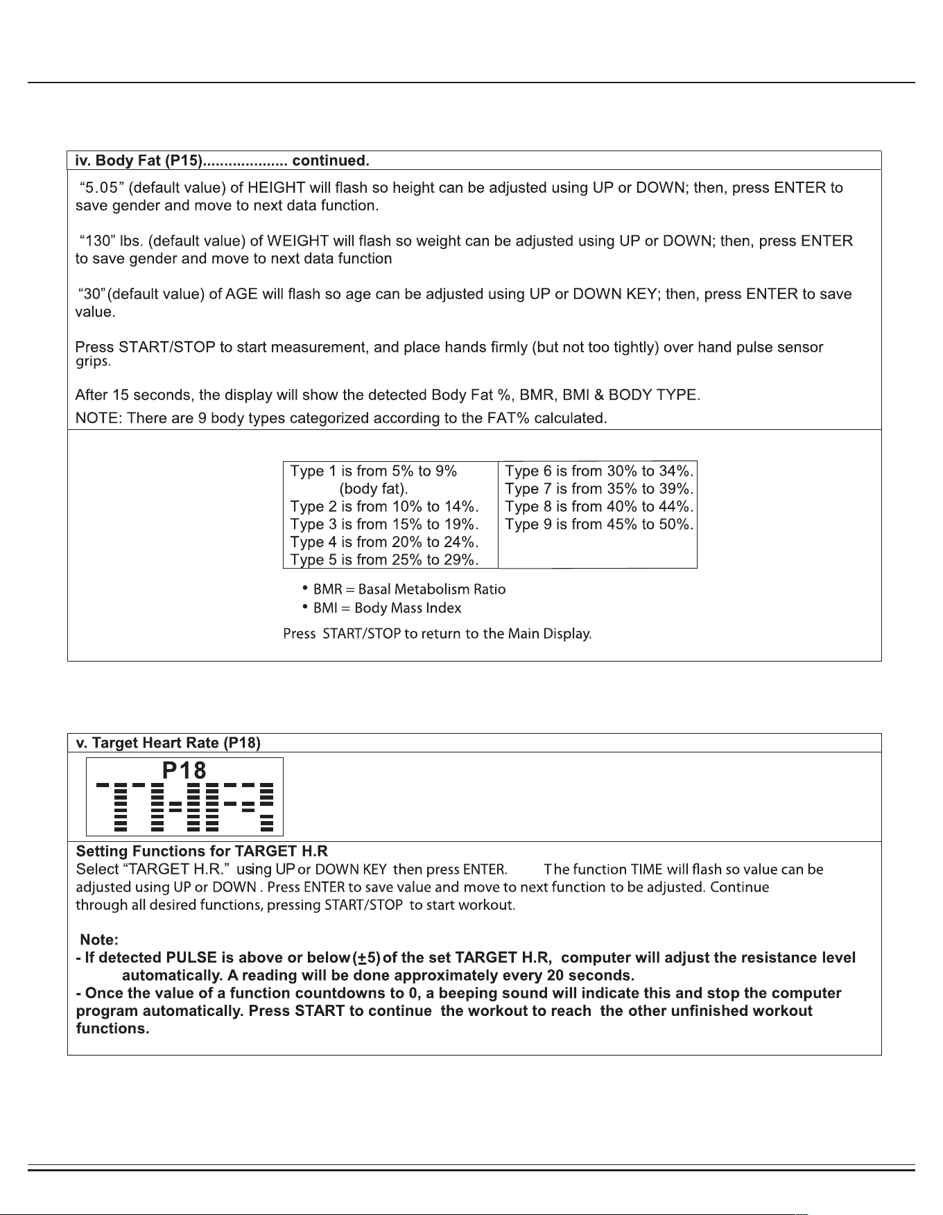
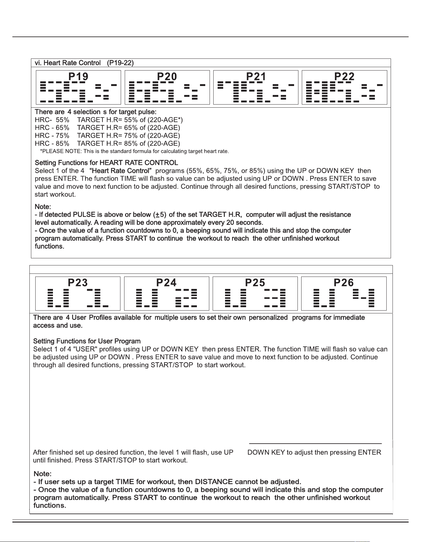
vii. User Custom Workout (P23-P26)
or

BR2998 Page 19
Safety and Maintenance
• To reduce speed on the elliptical, you may use the combinations of your feet on the Left/Right Pedal (#40/#41) and
your hands on the handlebars (#9/#10) to slow down safely and safely apply counter-momentum
• Wait for the pedals to come to a complete stop
• Now you may safely dismount the unit.
• Make sure all nuts, bolts, and screws are tightened prior to use.
• Be sure that all adjustment locking devices and safety devices are properly engaged prior to use!
• Never over-tighten the above-mentioned devices and parts to avoid damage to the unit.
• Check for loose parts and components and make proper adjustments prior to use.
• Check to see if there are any tears or bends in the welding or metal prior to use. If tears or bends are found,
DO NOT use the unit and contact our CUSTOMER SUPPORT.
• Extreme care must be taken to not allow your feet, ngers, hair, clothing, and/or any loose items to be snagged into any portion of
the bike when the unit is in motion. Failure to follow these instructions could result in serious injury, including the loss of ngers.
• Always wait for the pedals and other moving parts (which can gain great momentum during riding) to come to a
complete stop before dismounting the unit to avoid serious injury.
NOTE : Always wait for the pedals and/or any other moving parts (which can gain great momentum during exercise) to come to a com-
plete stop before dismounting the unit to avoid serious injury.
NOTE :
To safely move, transport, and/or store the unit, please seek the help of capable assistants (minimum of 2 people).
The unit has integrated spinning End Cap for Front Stabilizer (#52) purposely intended to help ease this process.
• Position one person on each side at the front of the bike (one person on the left, and one on the right).
• Have each person use both hands to grip the corresponding Pulse Handle Bar (#8) (These are the safest areas to avoid injury
during this process.)
• Have both people simultaneously lift the rear end of the unit, leaning the weight and pressure into the front of the unit and onto the
End Cap for Front Stabilizer (#52) to move/transport the unit to the desired area.
• Please review all safety instructions and warnings in this entire Owner’s Manual, as well as any safety/warning labels afxed to the
product before use.
• Do not use solvent cleaners. If you are in any doubt, do not use your cleansing product; contact CUSTOMER SUPPORT.
• The specic parts on your unit which may see possible signs of wear after prolonged use are listed as follows (please check these
parts before each use): Left Right Pedal (#40/41).
• For any replacement warning labels, please contact our CUSTOMER SUPPORT at
1 (888) 266-6789 or 1 (909) 598-9876, or mail in a written request to:
Body Flex Sports Inc.
21717 Ferrero Parkway
Walnut, CA 91789
More detailed information about how to reach our CUSTOMER SUPPORT may be found on Page 2 of the
Owner’s Manual under the “CUSTOMER SUPPORT” section.
Safety & Warning
How To (Emergency) Stop
How To Move/Transport The Unit
Storage
Maintenance & Care
BR2998 Page 20
Troubleshooting
NOTES (Regarding the Computer Monitor):
Warning: This device complies with Part 15 of the FCC Rules. Operation is subject to the following two conditions:
(1) This device may not cause harmful interference.
(2) This device must accept any interference received, including interference that may cause undesired operation.
Caution:
This equipment has been tested and found to comply with the limits for a Class B digital device, pursuant to part 15 of the FCC Rules.
These limits are designed to provide reasonable protection against harmful interference in a residential installation. This equipment generates, uses and can radiate radio frequency energy and, if not
installed and used in accordance with the instructions, may cause harmful interferenceto radio
communications. However, there is no guarantee that interference will not occur in a particular installation. If this equipment does cause harmful
interference to radio or television reception, which can be determined by turning the equipment off and on, the user is encouraged to try to correct the interference by one or more of the following mea-
sures:
- Reorient or relocate the receiving antenna.
- Increase the separation between the equipment and receiver.
- Connect the equipment into an outlet on a circuit different from that to which the receiver is connected.
- Consult the dealer or an experienced radio/TV technician for help.
(AFTER COMPLETE ASSEMBLY)
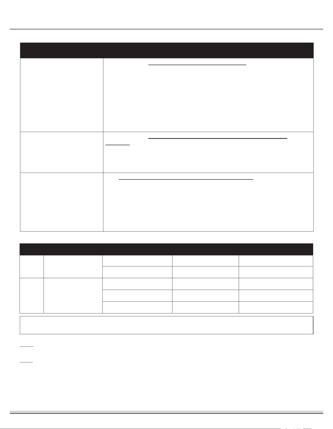
TROUBLESHOOT AREA SOLUTION
Hand Pulse Signal
If the computer is not picking up your hand pulse signal (or you are
getting inaccurate readings), please adjust the following:
1. Slightly moisten/dampen the palms with water so the sensors can detect a pulse
signal.
2. Do not grip the sensors too tightly. Only moderate pressure need be applied.
3. Gripping the sensors too tightly restricts and seizes detection of your pulse.
4. Remove any rings or jewelry to prevent interference.
5. Check to ensure all pulse sensor wires are properly connected and are not dam-
aged.
6. You may need to refer to installation/assembly directions for the pulse sensor
wires in this manual.
Calories/Distance/
Time (Etc.)
If the computer is not displaying the CALORIES/DISTANCE/TIME/(ETC.)
functions (or you are getting inaccurate readings), please adjust the following:
1. Check to ensure all computer sensor wires are properly
connected and are not damaged.
2. You may need to refer to installation/assembly directions for the sensor wires in
this manual.
Computer Display
If the computer display is blank & not displaying any data (or does not appear to
power on), please adjust the following:
1. Check to ensure all sensor wires are all properly connected and are not dam-
aged.
2. Check to ensure the AC Adapter* or Batteries* are properly plugged in or fully
charged.
3. Check your product manual to determine if your model uses either AC Adapter or
batteries to power your unit.
Computer Error Code Guide
For your safety, please do not discard this Troubleshooting sheet or the Owner’s Manual, and keep them in a place where you can easily access/
refer to them at any time. If you are still having any troubleshooting issues, please contact our Customer Support for further assistance.
Error Code Description Possible Reason Inspection Resolution
No Code No updates for the workout matrix
values on computer display during
exercise
(1) No sensor connectivity Check if sensor malfunction or sensor
position shifted
Replace sensor or reposition sensor to the
correct location
(2) Wiring or connection issue Check if sensor wire is broken or lose
connection
Reconnect or replace sensor wiring
E1 Motor Related Issues (1) Defective motor Check if motor damaged Replace motor
(2) Magnetic control system malfunction Check if magnetic control system is
damaged
Adjust or replace magnetic control system
(3) Bad wiring or connectivity issue Check for wire damage or loose con-
nection
Reconnect or replace motor wiring
BR2998 Page 21
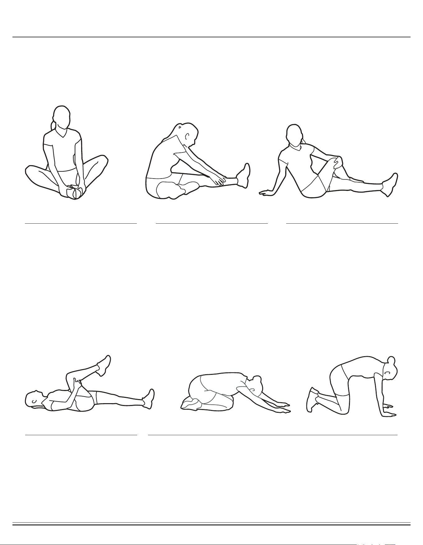
Warm-Up Instructions
1. Sit with your knees exed and
soles of feet together.
2. Hold your ankles and bend
at your hips (keep your back
straight) as you press your
knees toward the oor with your
elbows.
1. Lie on your back and raise
your right leg as you clasp both
hands under the back of the
knee. Keep your left leg straight.
2. Gently pull your right leg toward
your trunk without
raising your upper body. Switch
leg positions and repeat.
1. Sit with your left leg extended
and bend your right leg at the
knee as you place the sole of
your right foot against the inner
thigh of your extended leg.
2. Flex the foot of your extended
leg (toes pointed toward
ceiling) and gently bend forward
from your hips; keep your back
straight.
3. Reach your hands on your
extended leg as far as possible
and then switch legs and repeat.
1. Assume the depicted position on your hands and knees. Stretch your
hands out in front of you and then slowly start to pull them back in toward
your body as you tuck your chin and arch your back upward.
2. Return to the starting position slowly.
1. Sit with your leg extended and
bend your right knee as you
cross your right leg over your
left leg. Your right foot of your
extended leg foot should be at
on the oor alongside your left
knee.
2. Place your left arm on the
outside of your right leg and pull
against that leg while twisting
your trunk as far as possible to
the right. Place your right hand
on the oor behind your but-
tocks. Reverse leg positions and
repeat.
Before use, you must read and understand all instructions & warnings stated in this Owner’s Manual as well as posted
on the equipment. Before beginning any exercise program including the following exibility exercises, please consult with
your physician.
The following exibility exercises are provided to you as a means to prevent injury while you are exercising. A proper
warm-up routine decreases the chance of injuring your muscles while you are exercising. Please take the time to do these
exibility exercises before and after each time you exercise.
Groin Stretch
Groin Stretch
Hamstring Stretch
Trunk Flexion, Prone
Trunk Twister
BR2998 Page 22
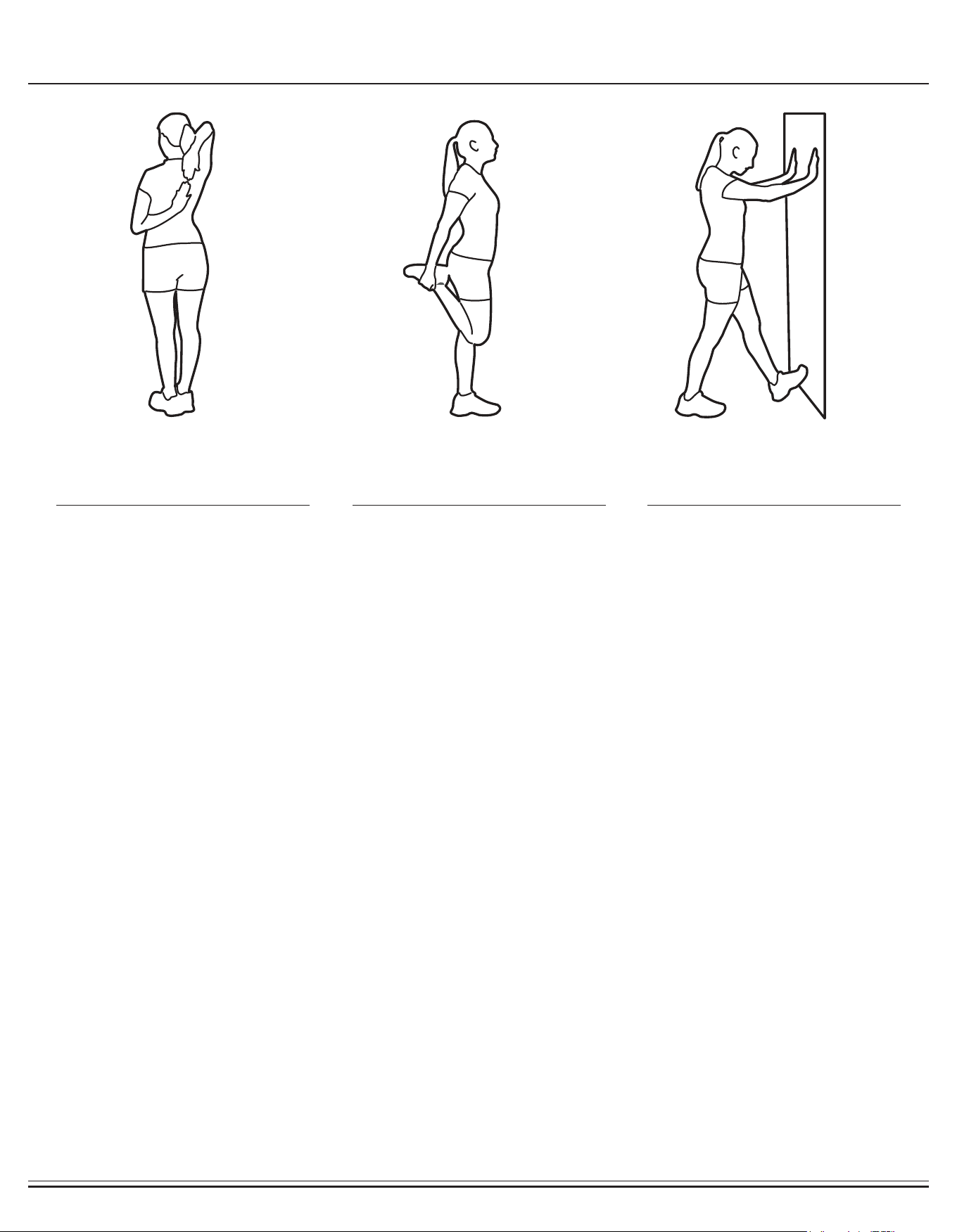
Warm-Up Instructions
1. Bring your right hand over your
right shoulder to the
upper back and bring your left
hand under your left shoulder to
the upper back.
2. Try to reach your ngertips. If
you are not able to reach your
ngertips, use a towel as an
extension of your hands and
gently pull one hand toward the
other.
Reverse arm positions and
1. Stand on your left leg and hold
onto a support with your left
hand.
2. Flex your right leg behind you,
grasp your ankle or foot with
your right hand and pull your
foot toward your buttocks. Keep
your back straight and right
knee pointed down.
Repeat on the other leg.
1. Place both hands against a wall
to aid your balance. Press the
ball of your left foot against the
wall and keep the heel of the
same foot rested on the oor
(make sure your left knee is
bent).
2. Slowly start to straighten your
left knee and you will feel the
muscles in your left calf stretch.
Switch leg positions and repeat.
Shoulder Stretch Quadriceps Stretch Calf Twister

THANK YOU FOR YOUR PURCHASE
MODEL NO.: BR2998
Please ll in the information below and keep this manual
along with your sales receipt as proof of purchase.
Serial Number :
Date of Purchase :
Retailer :
Body Flex Sports Inc.
21717 Ferrero Parkway
Walnut, CA 91789
Phone : 1 (888) 266-6789
Fax : 1 (909) 598-6707
Email : info@bodyexsports.com
Ver. 12/03/2018 Printed in China