
RS499
Parts List:
1. Force Screw
2. Centering Force Screw
3. Center Plate
4. Seal Installer
5. Hex Nut
6. Threaded Adapter
7. Remover Plates (3)
8. Sleeve Ring
www.matcotools.com
Page 1
Wear safety goggles.
(users and bystanders)
Usar gafas de seguridad.
(Usuarios y espectadores)
Porter des lunettes de
sécurité. (les utilisateurs et
les spectateurs)
www.matcotools.com
Page 2
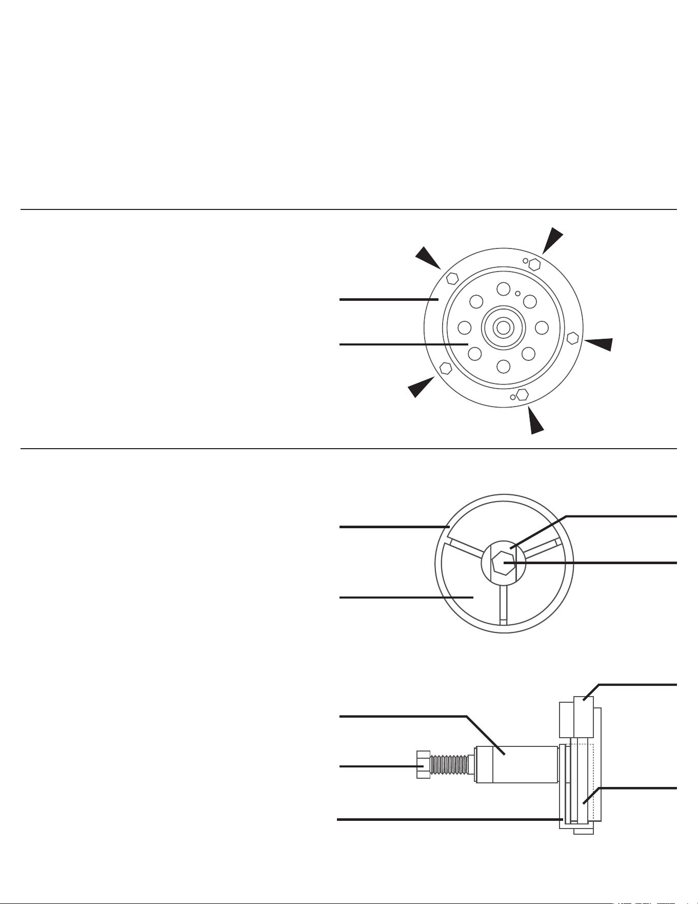
Seal Removal
1. Remove the bolts (5) from the rear seal
retainer as shown.
2. Clean all the RTV silicone from the sealing
surface but be careful not to damage the
crankshaft or surface.
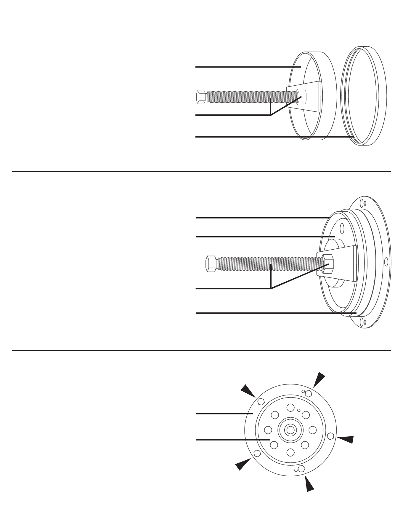
Wear Sleeve Removal (if equipped)
1. Insert the Centering Force Screw into the
Threaded Adapter.
2. Arrange the (3) Remover Plates over the
wear sleeve.
3. Place the Threaded Adapter and Centering
Force Screw so all Remover Plates are in
grove of the Threaded Adapter.
4. Slide the Sleeve Ring over the (3) Remover
Plates.
5. By hand, bottom out the Centering Force
Screw on the Crankshaft.
6. Turn the Centering Force Screw clockwise
to remove the wear sleeve.
Figure A
Figure B
Seal Housing
Sleeve Ring
Threaded Adapter
Centering Force Screw
Remover Plates
Parts List No. 7
(Three Required)
Parts List No. 8
Threaded Adapter
Parts List No. 6
C. Force Screw
Parts List No. 2
Remover Plates
Parts List No. 7
(Three Required)
Parts List No. 6
Sleeve Ring
Parts List No. 8
Wear Sleeve
Parts List No. 2
Crankshaft Flange
ALWAYS wear eye protection that meets ANSI Z87.1 and OSHA standards.
ALWAYS refer to the vehicle and engine specific manuals before doing any job.
This tool is NOT intended for non-Ford applications.
Images contained herein may not represent the actual vehicle.
This tool is meant to be used by professionally trained technicians.
NEVER strike, heat, attempt to alter or use this tool other than it’s intended purpose.
NOT INTENDED for use with pneumatic or other high impact tools.
Failure to comply with these rules will immediately VOID the manufacturer’s warranty.
www.matcotools.com
Page 3
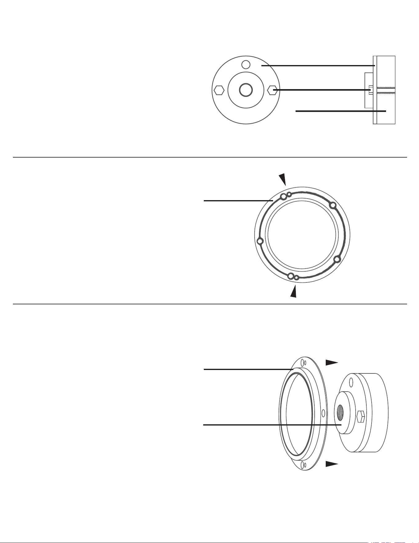
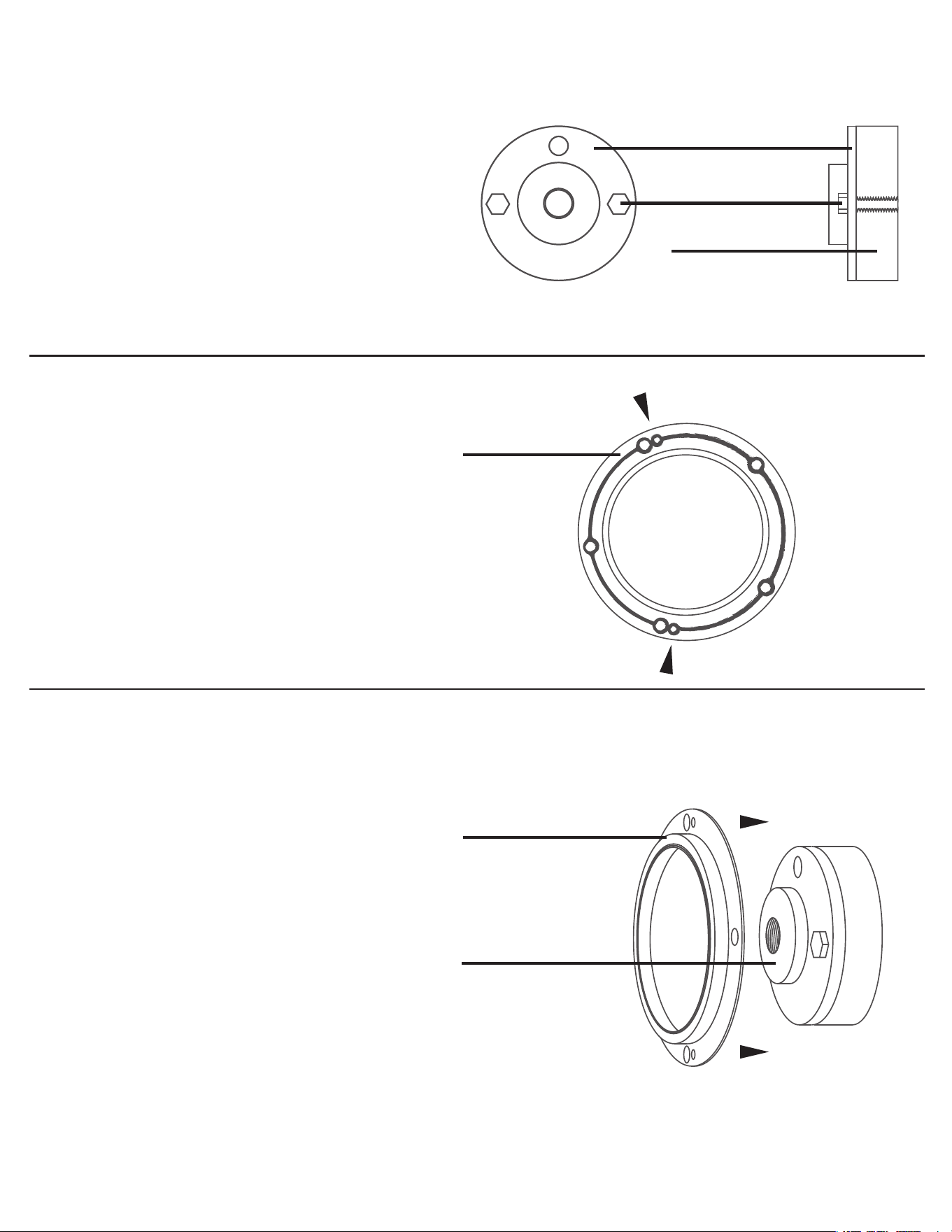
Seal Housing Sealing
1. Make sure the engine side of the seal
housing and block are clear of debris and
old sealant.
2. The seal housing installs only one way. Be
sure you are aware of the orientation
before applying sealant.
3. Apply a bead of RTV silicone to the engine
side of the seal housing. Be sure to apply
the sealant as shown.
Center Plate Installation
1. Attach the Center Plate to the crankshaft
flange with cap screws (not provided).
Figure D
Seal Housing Installation
1. Slide the seal and wear sleeve assembly
(with RTV silicone applied) over the
Centering Plate that has been firmly
secured to the crankshaft flange.
2. Make sure again the dowels are properly
aligned. Failure to do so can damage the
seal housing.
Figure E
Figure C
Center Plate
Parts List No. 3
Cap Screws
(not provided)
Crankshaft Flange
Centering Plate
Parts List No. 3
Seal and Wear Sleeve Assy.
Seal Housing
Align Dowel Pins
www.matcotools.com
Page 4
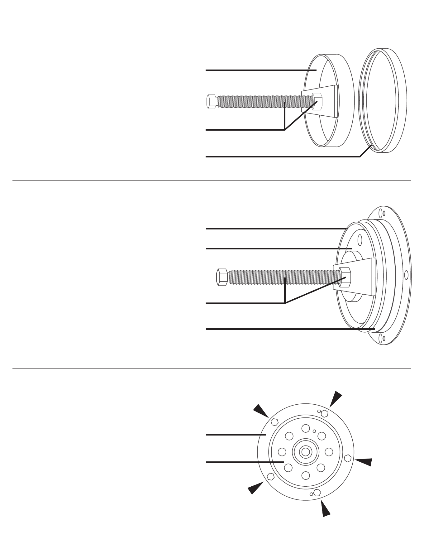
Installing Seal and Wear Sleeve
NOTE: Optionally, a light layer of a
non-hardening sealant, e.g. Loctite 209, can
be applied to the inside diameter surface of
the sleeve. Clean away sealant that migrates
to the shaft or sleeve outside diameter
surface.
1. Put the Seal Installer and Sleeve Ring
against the seal and wear sleeve, over the
Centering Plate. Thread the Force Screw
into the Centering Plate.
2. Turn the Hex Nut, bringing it in contact
with the Seal Installer.
3. Continue to tighten the Hex Nut, pressing
the seal and wear sleeve into position.
Figure G
Final Assembly
1. Tighten the seal housing bolts to the
manufacturer’s specifications.
Figure H
Seal / Wear Sleeve Installer Assembly
1. Thread the hex nut onto the Force Screw.
2. Thread the Force Screw with the Hex Nut
into the Seal Installer.
3. Put the Sleeve Ring over the Seal Installer.
Figure F
Seal Housing
Crankshaft Flange
Seal Installer
Parts List No. 4
Centering Plate
Parts List No. 3
Seal Installer
Parts List No. 4
Force Screw and Hex Nut
Parts List No. 1 and No. 5
Force Screw and Hex Nut
Parts List No. 1 and No. 5
Sleeve Ring
Parts List No. 8
Sleeve Ring
Parts List No. 8

RS499
Lista De Piezas:
1. Tornillo de fuerza
2. Tornillo de fuerza de
centrado
3. Placa centro
4. Instalador de sellos
5. Tuerca hexagonal
6. Adaptador de rosca
7. Placa de extracción (3)
8. Anillo de manguito
www.matcotools.com
Page 1
Wear safety goggles.
(users and bystanders)
Usar gafas de seguridad.
(Usuarios y espectadores)
Porter des lunettes de
sécurité. (les utilisateurs et
les spectateurs)

www.matcotools.com
Page 2
Desmontaje de la junta
1. Quite los tornillos (5) de la sujeción de la
junta trasera tal como se muestra.
2. Elimine toda la silicona RTV de la
superficie de sellado con cuidado de no
dañar el cigüeñal ni la superficie.
Desmontaje del protector (si está
instalado)
1. Introduzca el tornillo de centrado en el
adaptador roscado.
2. Coloque las placas del extractor (3) sobre
el protector.
3. Coloque el adaptador roscado y el tornillo
de centrado de forma que todas la placas
del extractor se coloquen en el adaptador
roscado.
4. Deslice el anillo del protector por las
placas del extractor (3).
5. De forma manual, haga que el tornillo de
centrado toque el fondo del cigüeñal.
6. Gire hacia la derecha el tornillo de
centrado para quitar el protector.
Gráfico A
Gráfico B
Carcasa de sellado
Anillo del protector
Adaptador roscado
Tornillo de fuerza de
Adaptador roscado
Lista de piezas 7
(Se requieren tres)
Lista de piezas 8
Adaptador roscado
Lista de piezas 6
Tornillo de fuerza
de centrado
Lista de piezas 2
Placa de extracción
Lista de piezas 7
(Se requieren tres)
Lista de piezas 6
Anilli de manguito
Lista de piezas 8
El Protector
Lista de piezas 2
Brida del cigüeñal
USE SIEMPRE PROTECCIÓN OCULAR CONFORME CON LA NORMA ANSI Z87.1 Y LAS NORMAS DE LA OSHA.
ANTES DE REALIZAR CUALQUIER OPERACIÓN, CONSULTE SIEMPRE LOS MANUALES ESPECÍFICOS DEL VEHÍCULO Y
DEL MOTOR.
ESTA HERRAMIENTA NO SE HA DISEÑADO PARA APLICACIONES QUE NO SEAN DE FORD.
ES POSIBLE QUE LAS IMÁGENES QUE SE INCLUYEN NO REPRESENTEN EL VEHÍCULO REAL.
ESTA HERRAMIENTA SE HA DISEÑADO PARA TÉCNICOS CAPACITADOS.
NO GOLPEE, CALIENTE, INTENTE MODIFICAR NI UTILICE ESTA HERRAMIENTA CON FINES DIFERENTES A LOS
PREVISTOS.
NO SE HA DISEÑADO PARA SU USO CON HERRAMIENTAS NEUMÁTICAS O DE GRAN IMPACTO.
EL INCUMPLIMIENTO DE ESTAS NORMAS SUPONE LA ANULACIÓN INMEDIATA DE LA GARANTÍA DEL FABRICANTE.
www.matcotools.com
Page 3
Sellado de la carcasa
1. Asegúrese de que no hay residuos ni
restos de sellador en el lado del motor de
la carcasa de sellado y del bloque.
2. La carcasa de sellado se instala solamente
con una orientación. Asegúrese de que
sabe cuál es la orientación correcta antes
de aplicar el sellador.
3. Aplique un cordón de silicona RTV en el
lado del motor de la carcasa de sellado.
Aplique el sellador tal como se muestra.
Instalación de la placa central
1. Fije la placa central a la brida del cigüeñal
con los tornillos de sombrerete (no
suministrados).
Gráfico D
Instalación de la carcasa de sellado
1. Deslice el conjunto de la junta y del
protector (con silicona RTV) por la placa de
centrado que se ha fijado correctamente a
la brida del cigüeñal.
2. Asegúrese de que las espigas están bien
alineadas. En caso contrario, se producirán
daños en la carcasa de sellado.
Gráfico E
Gráfico C
Placa centro
Lista de piezas 3
Tornillos de sombrerete
(no suministrados)
Brida del cigüeñal
Placa centro
Lista de piezas 3
Carcasa de sellado
Carcasa de sellado
Alinear pasadores
www.matcotools.com
Page 4
Instalación de la junta y del protector
NOTA: De forma opcional, se puede aplicar
una capa final de sellador que no se
endurece, como Loctite 209, en la superficie
del diámetro interior del protector. Elimine
los restos de sellador de la superficie del
diámetro exterior del eje o del protector.
1. Coloque el dispositivo de instalación de la
junta y el anillo del protector en la junta y
el protector, concretamente sobre la placa
de centrado. Enrosque el tornillo de
centrado en la placa de centrado.
2. Gire la tuerca hexagonal de forma que
entre en contacto con el dispositivo de
instalación de la junta.
3. Siga apretando la tuerca hexagonal de
forma que la junta y el protector queden
fijados en su posición.
Gráfico G
Montaje final
1. Apriete los tornillos del carcasa de sellado
de acuerdo con las especificaciones del
fabricante.
Gráfico H
Conjunto de la junta y del dispositivo de
instalación del protector
1. Enrosque la tuerca hexagonal en el tornillo
de centrado.
2. Enrosque el tornillo de centrado con la
tuerca hexagonal en el dispositivo de
instalación de la junta.
3. Coloque el anillo del protector en el
dispositivo de instalación de la junta.
Gráfico F
Carcasa de sellado
Brida del cigüeñal
Instalador de sellos
Lista de piezas. 4
Placa centro
Lista de piezas 3
Instalador de sellos
Lista de piezas 4
Tornillo de fuerza y
Tuerca hexagonal
Lista de piezas 1 y 5
Tornillo de fuerza y
Tuerca hexagonal
Lista de piezas 1 y 5
Anilli de manguito
Lista de piezas 8
Anilli de manguito
Lista de piezas 8