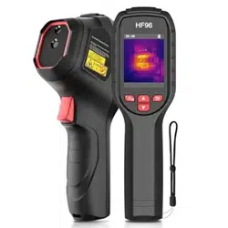

Handheld Thermal Camera
User Manual

CONTENTS
1 Introduction .......................................................................................................................................... 1
1.1 Introduction of Our Product ........................................................................................................................................... 1
1.2 Main Function .................................................................................................................................................................... 1
2 Appearance ........................................................................................................................................... 1
2.1 Components ....................................................................................................................................................................... 1
3 Preparation ........................................................................................................................................... 4
3.1 Charge Device.................................................................................................................................................................... 4
3.2 Power On/Off .................................................................................................................................................................... 4
3.2.1 Set Auto Power-off Duration ............................................................................................................................ 4
3.2.2 Set Auto Sleep ...................................................................................................................................................... 4
3.3 Live View ............................................................................................................................................................................ 5
4 Start With Scene Mode ......................................................................................................................... 5
4.1 Select a Scene Mode ....................................................................................................................................................... 5
4.2 (Optional) Set Scene Mode Parameters .................................................................................................................... 7
5 Precise Temperature Measurement .................................................................................................... 8
5.1 Set Temperature Measurement Parameters ............................................................................................................. 8
5.1.1 Adjust Distance ..................................................................................................................................................... 8
5.1.2 Adjust Emissivity .................................................................................................................................................. 8
5.1.3 (Optional) Adjust Other Parameters ............................................................................................................... 9
5.2 Set Measurement Tools .................................................................................................................................................. 9
5.3 Set Thermometer Mode (If Applicable) ..................................................................................................................... 9
6 Set Alarms........................................................................................................................................... 10
7 Display Settings .................................................................................................................................. 10
7.1 Set Super Resolution ..................................................................................................................................................... 10
7.2 Set Image Mode .............................................................................................................................................................. 11
7.3 Set Color Distribution ................................................................................................................................................... 11
7.4 Set Palettes ...................................................................................................................................................................... 11
7.5 Set Level & Span............................................................................................................................................................. 11
7.6 Display OSD Info ............................................................................................................................................................. 12
8 Snapshots and Videos ........................................................................................................................ 12
8.1 Capture Snapshots ......................................................................................................................................................... 12
8.2 Record Video ................................................................................................................................................................... 12
8.3 View Snapshots and Videos ........................................................................................................................................ 13
8.3.1 View Snapshots .................................................................................................................................................. 13
8.3.2 View Videos......................................................................................................................................................... 13
8.4 Export Snapshots ........................................................................................................................................................... 13
9 Cast Screen ......................................................................................................................................... 13

10 Maintenance ...................................................................................................................................... 14
10.1 View Device Information ............................................................................................................................................ 14
10.2 Set Language ................................................................................................................................................................. 14
10.3 Save Operation Logs ................................................................................................................................................... 14
10.4 Format Storage ............................................................................................................................................................. 14
10.5 Upgrade .......................................................................................................................................................................... 14
10.6 Restore Device ............................................................................................................................................................. 14
11 Frequently Asked Questions (FAQ) .................................................................................................. 15
1
1 Introduction
1.1
Introduction of Our Product
The handheld thermal camera is a camera with thermal and optical images. The built-
in high-sensitivity IR detector and high-performance sensor detect the temperature
change and measure the real-time temperature.
The handheld thermal camera is based on the thermal technology, specially designed
for the needs of temperature measuring applications. People can quickly
troubleshoot faults on-site.
1.2
Main Function
Scene (If Applicable)
The camera supports multiple scene modes for different detection targets and
scenarios. Some scene modes support IntellFault, an intelligent function. It can assist
in anomaly detection and give prompts on top of the live view interface.
Temperature measurement
Device detects the real-time temperature, and display it on the screen.
Super Resolution
The device adopts super resolution technology in live streaming, making live image
clearer and with more details. Go to Settings > Super Resolution to enable the
function.
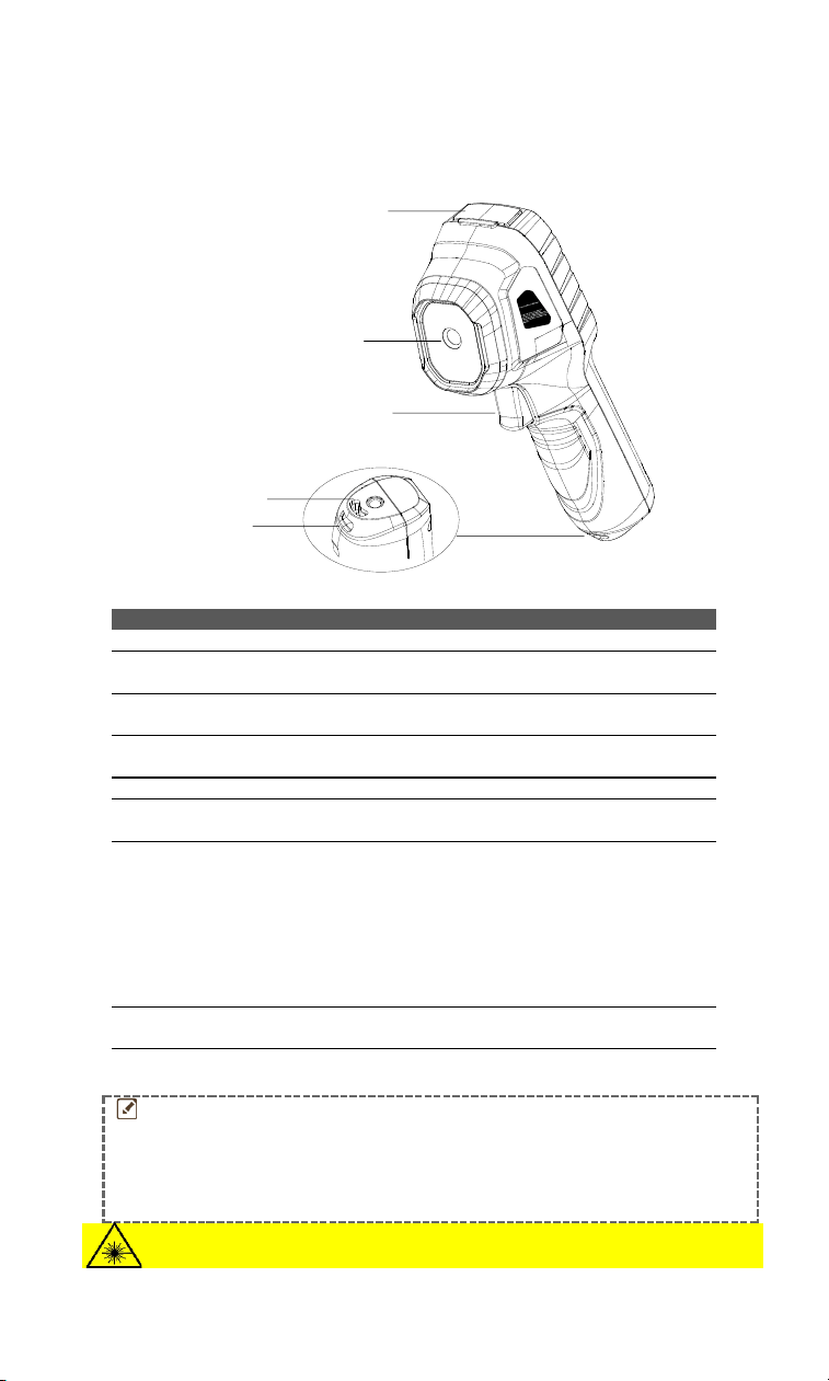
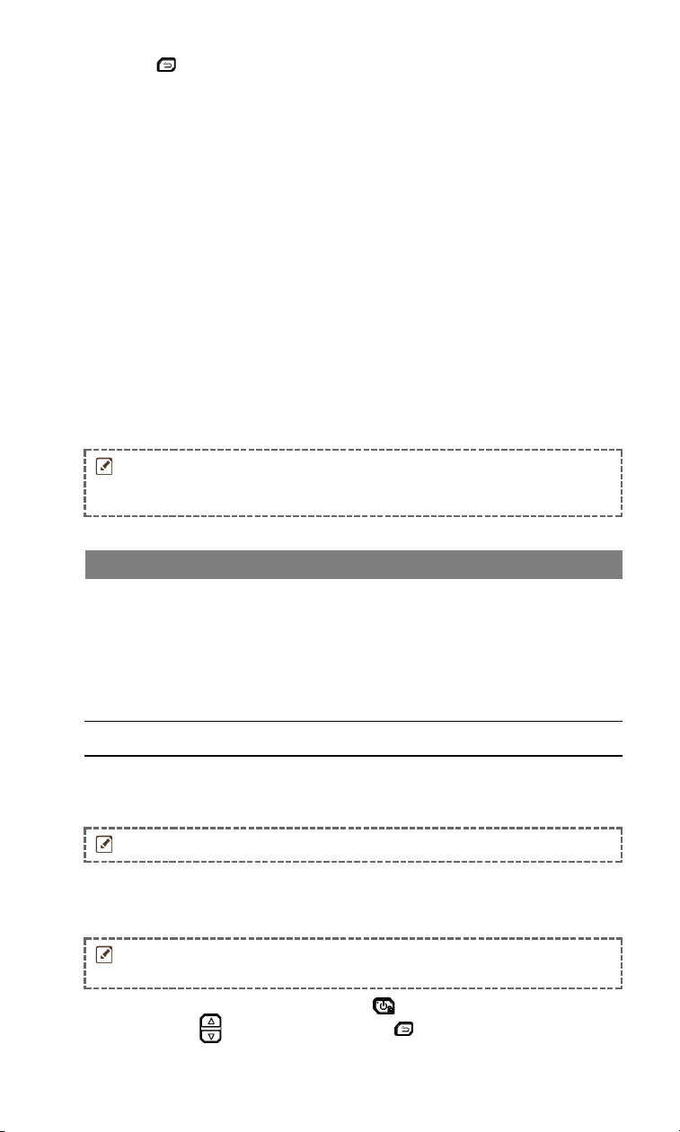
2 Appearance
2.1
Components
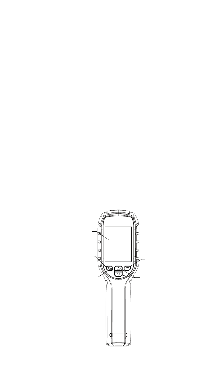
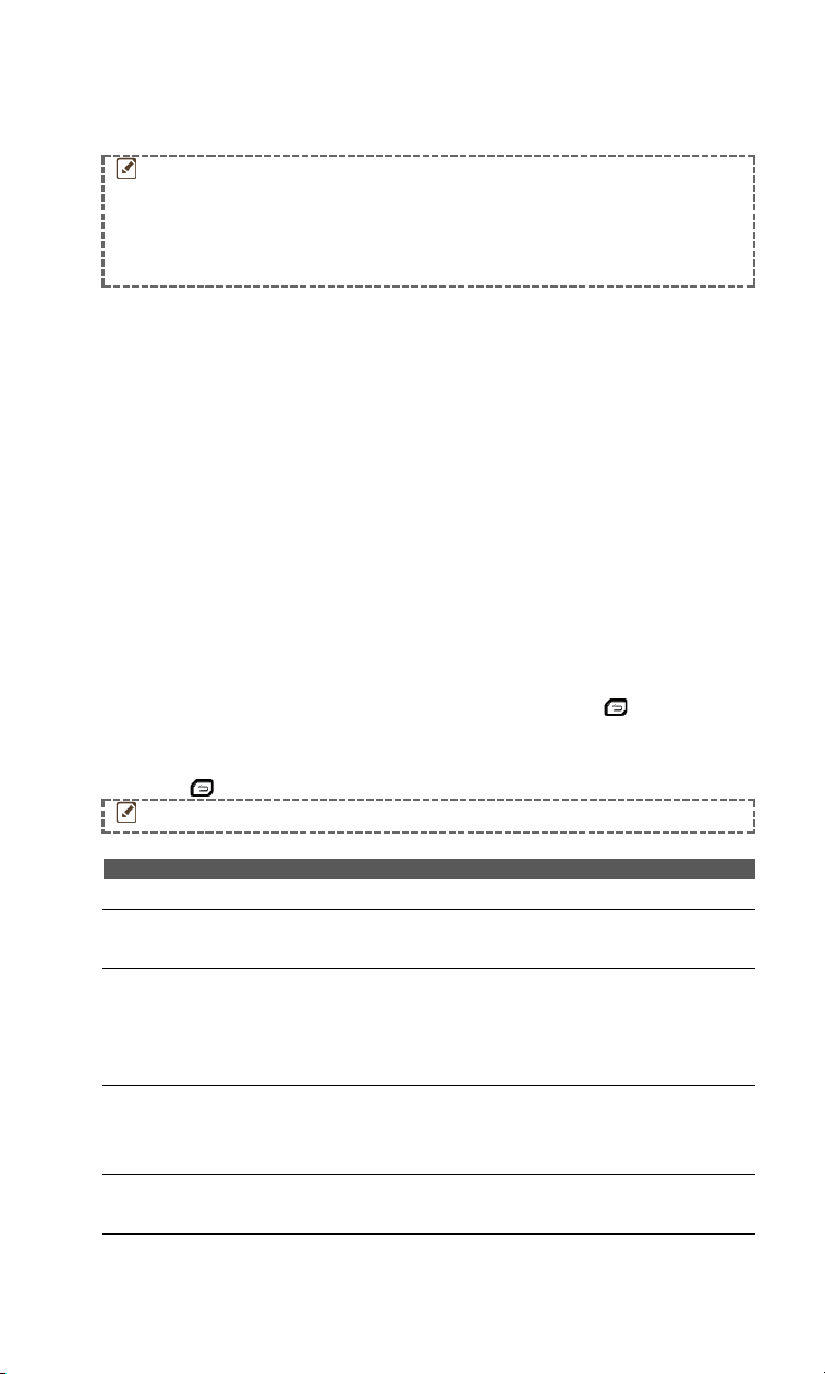
Screen
Charging
Indicator
Power/OK
/Menu
Back
Navigation
2
Button
Function
Hold: Power On/Off
Press: Display menu or confirm operation
Exit the menu or return to previous menu.
In menu mode: Press and to select parameters.
In live view mode: Press to switch image modes (only
supported by certain models). Press to switch
palettes.
Appearance 1
Type-C Interface
Laser
Thermal Lens
Trigger
Optical Lens
Tripod Mount
Wrist Strap Hole
Appearance 2
Type-C Interface
Laser
Thermal Lens
Trigger
Tripod Mount
Wrist Strap Hole
3
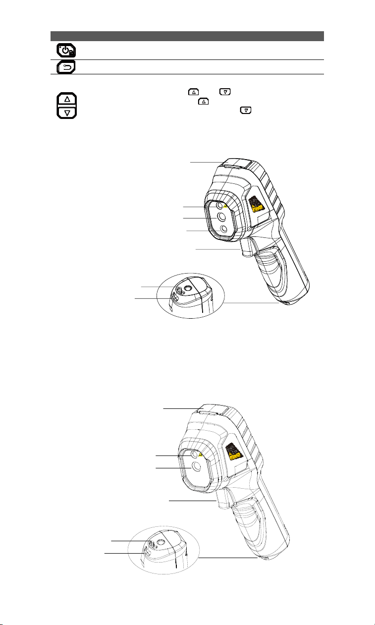
Appearance 3
Type- C Interface
Thermal Lens
Trigger
Tripod Mount
Wrist Strap Hole
Component
Function
Screen
Views live view.
Charging
Indicator
● Solid Red: Charging.
● Solid Green: Fully charged.
Type-C
Interface
Charge the battery or export snapshots.
Laser
Locates the target with laser light (only supported by
certain models).
Thermal Lens
Generates thermal images.
Optical Lens
Generates optical images (only supported by certain
models).
Trigger
In live view:
● Press: Capture snapshots.
● Hold:
1) Locate the target with laser light (for the models with
laser light), and release to capture snapshots.
2) Record videos (if the laser is on, turn on the Record
switch before recording).
In menu mode, press the trigger to go back to live view.
Wrist Strap
Hole
Mounts the wrist strap.
Tripod Mount
Connect to UNC 1/4”-20 tripod.
NOTE
● The appearance and button functions vary according to different
models.
● The optical lens is only supported by certain models. Please
refer to the actual device or datasheet.
● The warning sign is beside the laser and on the left side of the
device.
Warning:
4
The laser radiation emitted from the device can cause eye injuries, burning of skin or
inflammable substances. Prevent eyes from direct laser. Before enabling the Light
Supplement function, make sure no human or inflammable substances are in front of
the laser lens. The wave length is 650 nm, and the power is less than 1 mW. The
divergence angle is 0.05° ± 0.01° . The laser meets the IEC 60825-1:2014 standard.
Protective eyewear can protect persons against laser sources. The operating
wavelength of the eyewear should be longer than the laser peak wavelength, and the
optical density should be higher than 0D5+.
3 Preparation
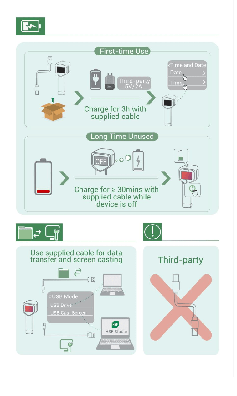
3.1
Charge Device
1. Lift the type-C interface cover.
2. Connect the device to power supply using the type-C cable to charge the device.
Type-C Interface
NOTE
● The power delivered by the charger must be between min 6.7
Watts required by the radio equipment, and max 10 Watts in
order to achieve the maximum charging speed.
● The device is equipped with the built-in battery. For the first
charge, charge the device for more than 3 hours when the device
is turned on. Do not use the USB-C to USB-C cable from other
manufacturers.
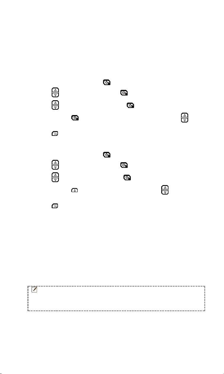
3.2
Power On/Off
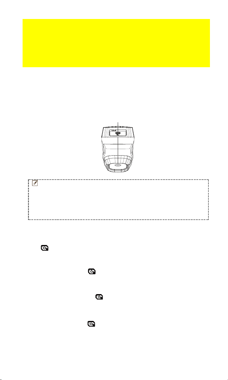
Power On
Hold for over six seconds to turn on the device. You can observe the target when
the interface of the device is stable.
Power Off
When the device is on, hold for six seconds to power off the device.
3.2.1 Set Auto Power-off Duration
In the live view interface, press and go to More Settings > Auto Power-off to set
the automatic shutdown time for device as required.
3.2.2 Set Auto Sleep
In live view interface, press , and go to More Settings > Auto Sleep to set the
waiting time before auto sleep. When there is no button pressing on the device for
more than the set waiting time, the device enters sleep mode automatically. Press a
button to wake the device up.
5
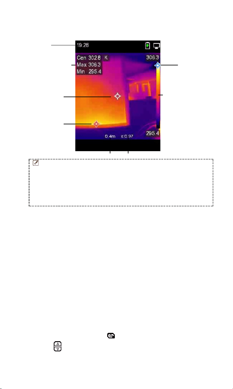
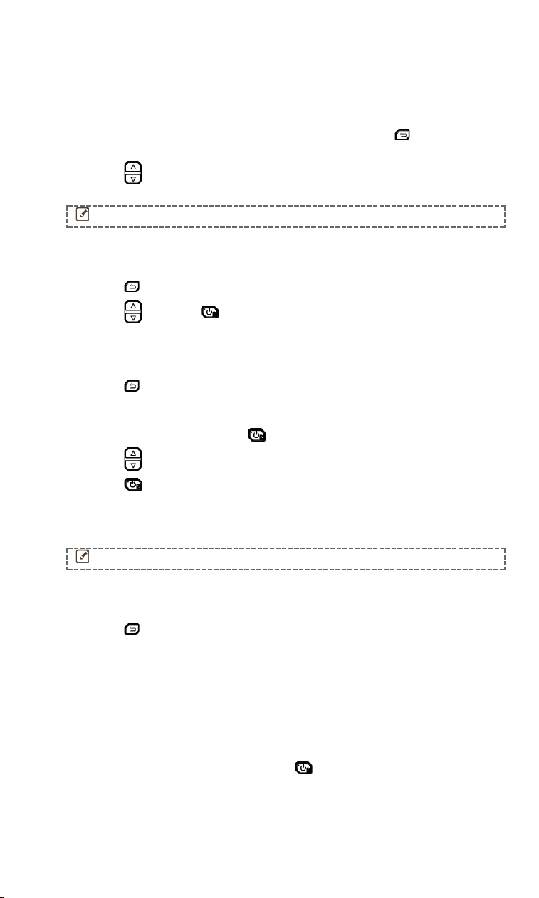
3.3
Live View
The live view interface of different models may vary. Take the actual product for reference.
Time
Real-time
Temperature
Satus Icons
Color -
Temperature scale
Max.
Temperature
Display
Min.
Temperature
Display
Distance Emissivity
Center
Temperature
Display
NOTE
● Because this manual is updated on a regular basis, the live view
might be slightly different from the version of your particular
camera model. Please refer to the actual camera.
● If the temperature value is preceded by a "~", it indicates that the
temperature measurement function has not reached a precise
state. This symbol usually appears during the device startup
phase and disappears once the temperature measurement
function is fully operational.
4 Start With Scene Mode
To conduct fast anomaly detection, several preset templates are included in Scene
mode for various detection scenarios. Users can choose an appropriate scene or
customize a scene as per targets, and set high temperature alarm as needed.
Scene mode is ONLY supported by some models in the series. Please refer to your
actual device and its software version.
1. Select an appropriate scene mode. See 4.1 Select a Scene Mode for details.
2. (Optional) Fine-tune scene mode parameters as needed. See 4.2 (Optional) Set
Scene Mode Parameters for details.
3. (Optional) Set alarms as needed. See 6 Set Alarms for details.
4. Observe detection results in live view interface.
4.1
Select a Scene Mode
Choose a scene mode according to the faults or anomalies you want to locate in a
specific detection scene. It is ONLY supported by some models in the series.
1. In the live view interface, press and go to Scene > Scene.
2. Press to select an appropriate scene mode.
6
NOTE
Default value of parameters work for most cases. If users want to
fine-tune the related parameters as needed, see 4.2 (Optional) Set
Scene Mode Parameters
.
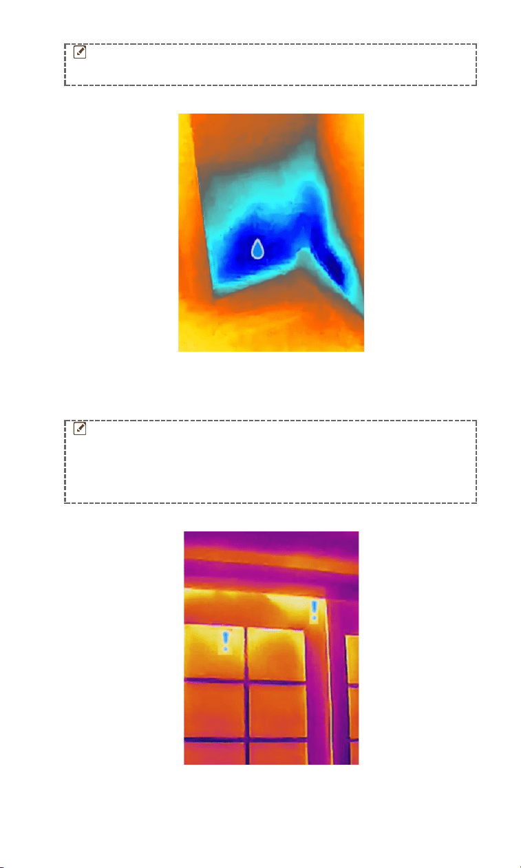
Water Leak
To inspect the water leak of building ceilings, walls and floors indoors.
IntellFault technology can assist in fast recognition for anomalies during water leak
detection. When IntellFault is enabled and water leak anomalies are detected, Suspect
will be displayed on top of live view.
NOTE
●
False positives and false negatives emerge when temperature
difference of the areas with leak anomalies is too subtle to be
recognized, or the thermal imaging features are not obvious.
●
It is recommended to give a second diagnosis based on
IntellFault function. The algorithm of IntellFault function is
being updated.
Insulation
To detect indoor insulation deficiency of building walls, ceilings, common users can
apply this scene.
7
IntellFault technology can assist in fast recognition for anomalies during insulation
detection. When IntellFault is enabled and insulation anomalies are detected, Suspect
will be displayed on top of live view.
NOTE
●
False positives and false negatives emerge when temperature
difference of the areas with leak anomalies is too subtle to be
recognized, or the thermal imaging features are not obvious.
●
It is recommended to give a second diagnosis based on
IntellFault function. The algorithm of IntellFault function is
being updated.
Floor Heating
To detect and observe the faults of floor heating system.
Electrical Faults
To detect and observe the faults of wires, circuits, and electrical components,
terminators, etc.
Solar Panel
To detect and observe the faults of solar panels.
Custom
Users can customize a mode to save desired temperature measurement parameters
for future use. See 4.2 (Optional) Set Scene Mode Parameters.
4.2
(Optional) Set Scene Mode Parameters
To obtain a more precise detection results, users can fine-tune the related
parameters.
1. In Scene mode, choose an appropriate scene and then press to set
parameters.
2. Adjust the parameters according to the table.
3. Press to save and exit.
NOTE
Parameters vary from the different scenes.
Parameters
Description
Emissivity
Set the emissivity according to your target.
Palettes
Thermal images are created by temperature difference. Users
can switch different palettes as preferred.
Level & Span
Temperature scale on right side supports browsing color-
temperature relationship in the image. Set the level & span
parameters to get better image contrast. See 7.5 Set Level &
Span.
Temperature
Range
Select the temperature measurement range. The device can
detect the temperature and switch temperature measurement
range automatically in Auto Switch mode.
Alarm
When the temperature of targets triggers the set alarm rule,
users can be notified in the set ways. See 6 Set Alarms.
Color
Distribution
Linear and Histogram modes are selectable for different
application scenes, so as to display more details.

8
● Linear: Detect small high temperature targets in low
temperature background to enhance and display more
details of high temperature targets, such as cable
connectors.
● Histogram: Detect small low temperature targets in high
temperature areas to enhance temperature difference and
remain details of low temperature objects, such as cracks.
5 Precise Temperature Measurement
To get more precise and real-time temperature of the target, user can set spot tools
and alarm as needed.
1. For models with scene modes, select a proper scene to speed up the
measurement settings. See 4 Start With Scene Mode.
2. Verify temperature values in the top-left corner of live view. If they are not
precise enough, fine-tune temperature measurement parameters. See 5.1.3
(Optional) Adjust Other Parameters.
3. (Optional) Users set spot tools to get the real-time temperature of the
highest/lowest/center temperature spot. See 5.2 Set Measurement Tools.
4. (Optional) Set the alarm. The target whose temperature value is above or below
the set threshold value can trigger the alarm. See 6 Set Alarms.
5.1
Set Temperature Measurement Parameters
You should set temperature measurement parameters before measuring
temperature.
5.1.1 Adjust Distance
The distance between the camera and the observation target affects the accuracy of
the temperature results. Before temperature measurement, users should set the
distance first.
1. In the live view interface, press to show the menu.
2. Press to select Distance, and then set parameters.
3. Press to save and exit.
5.1.2 Adjust Emissivity
Emissivity directly affects the measurement accuracy and it is necessary to be re-
adjusted according to the characteristics of the target material.
For models with scene mode:
1. In Scene mode, choose an appropriate scene and then press to set
parameters.
2. Adjust the parameters.
3. Press to save and exit.
For models without scene mode:
1. In the live view interface, press to show the menu.
9
2. Press to select Emissivity, and then set parameters.
3. Press to save and exit.
5.1.3 (Optional) Adjust Other Parameters
To improve the accuracy of temperature measurement, fine-tune temperature
measurement parameters.
● Temperature Range: Go to Settings > Temperature Range, and select the
temperature measurement range. The device can detect the temperature and
switch temperature measurement range automatically in Auto Switch mode.
● Unit: Go to Display Settings > Unit, and press to set the temperature unit.
5.2
Set Measurement Tools
Device measures the temperature of the whole scene and can be managed to display
the center, hot, and cold spot in the scene.
1. In the live view interface, press to show the menu.
2. Press to select Display Settings.
3. Select the desired spots to show their temperatures, and press to enable
them.
Hot: Display the hot spot in the scene and show the max. temperature.
Cold: Display the cold spot in the scene and show the min. temperature.
Center: Display the center spot in the scene and show the center temperature.
4. Press to save and exit. The device shows the real-time temperature on the
upper left side of live view interface.
NOTE
If there is serious inaccuracy in temperature results, turn off
IntellAccu button by Settings > IntellAccu. IntellAccu function is
ONLY supported by some models.
5.3
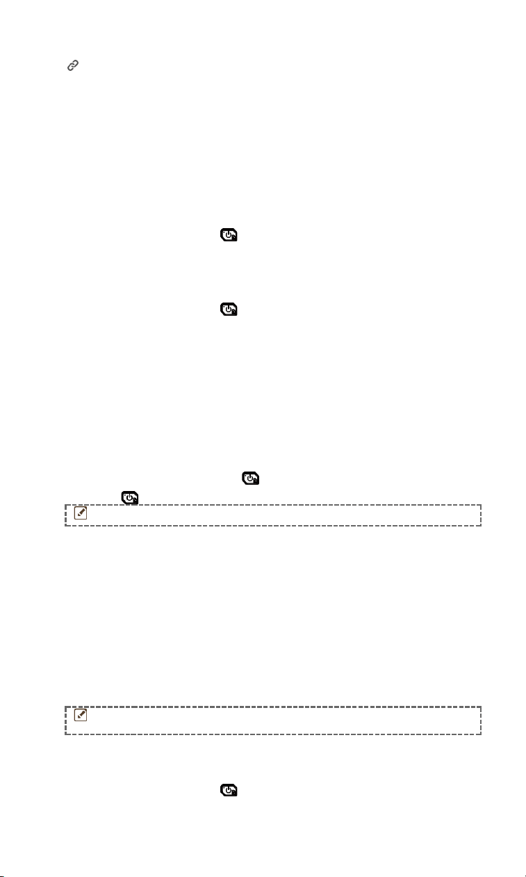
Set Thermometer Mode (If Applicable)
The Thermometer Mode utilizes a laser pointer to help users quickly locate
temperature measurement points. When enabled, the laser pointer indicates the
target in the scene, allowing users to visualize its temperature in real time. Devices
without laser do not support this mode.
1. In the live view, press to show the menu, then press to enable
Thermometer Mode. Press to save and exit.
2. In the live view, hold the trigger. The device will emit laser to aim at the target. A
red laser indicator dot will appear at the center of the screen, accompanied by
the temperature value of the target (consistent with the center point
temperature).
3. Release the trigger.
● If video recording is enabled (see 8.2 Record Video ), the device will continue
recording, and the laser dot will disappear.
● If video recording is not enabled, the device will automatically capture an
image of the current scene and save the temperature data.
NOTE
●
In Thermometer Mode, the laser pointer cannot be turned off. To
turn off the laser, disable this mode first.
●
In Thermometer Mode, the maximum, minimum, and center
temperature values are not displayed in the top-left corner of
the observation interface.
10
6 Set Alarms
Set the alarm rules and the device will alarm when the temperature triggers the rule.
For models with scene mode:
1. In Scene mode, choose an appropriate scene and then press to set
parameters.
2. Press , and turn on Alarm.
NOTE
ONLY some scenes support Alarm. Please refer to your actual device.
3. Select Measurement to set the alarm rule. Select Alarm Threshold to set the
threshold temperature. When the target’s temperature is higher or lower than the
threshold value, the device will output alarm.
4. Press to save and exit.
5. Press , and press to enable the Alarm Linkage function.
Alarm Mode Palettes: When the target’s temperature is higher than the set value,
the target will become red; when the target’s temperature is lower than the set
value, the target will become blue (only supported by certain models).
6. Press to save and exit.
For models without scene mode:
1. In the live view interface, press to show the menu.
2. Press , and select Alarm and turn it on.
3. Press to enable the Alarm Linkage function.
Alarm Mode Palettes: When the target’s temperature is higher than the set value,
the target will become red; when the target’s temperature is lower than the set
value, the target will become blue (only supported by certain models).
NOTE
The flash light will turn off automatically after enabling flashing alarm.
4. Select Measurement to set the alarm rule. Select Alarm Threshold to set the
threshold temperature. When the target’s temperature is higher or lower than the
threshold value, the device will output alarm and other alarm linkage.
5. Press to save and exit.
7 Display Settings
7.1
Set Super Resolution
The device supports Super Resolution on live view (for some models) and on
snapshots. Turn on Super Resolution to enhance the object outlines for better image
display. The actual effect is subject to the actual product.
Go to Settings > Super Resolution, and press to turn it on/off.
On live view: For some models, the object outlines can be enhanced in live view
when super resolution is on.
On captured images: The object outlines in the image are enhanced after super
resolution is on.
11
7.2
Set Image Mode
You can set image modes of the device. Image Mode is only supported by certain
models. Please refer to the actual device or the datasheet.
1. Select an image mode by the following ways:
Go to Settings > Image Settings > Image Mode, and select a preferred image
mode.
Press in live view to switch image modes.
Image Mode
Description
Thermal
Display the thermal image only.
Fusion
Fuse the optical image with the thermal image. The
fused image with clear edge is displayed in this mode.
Visual
Visual object image only. This function is only
supported by the models with visual lens.
2. Press to save and exit.
NOTE
Your camera will periodically perform a self-calibration to optimize
image quality and measurement accuracy. In this process the
image will pause briefly and you will hear a “click” as a shutter
moves in front of the detector. The self-calibration will be more
frequent during the startup or in very cold or hot environments.
This is a normal part of operation to ensure optimum performance
for your camera.
7.3
Set Color Distribution
Color distribution allows you to adjust image effects. You can select histogram or
linear pattern. Histogram is suitable for scenarios with large temperature difference,
and linear pattern is suitable for scenarios with small temperature difference. You
can go to Settings > Image Settings > Color Distribution to select histogram or linear
pattern.
7.4
Set Palettes
The palettes allow you to select the desired colors. You can switch palettes by the
following ways:
Go to Settings > Palettes to select a preferred palette, and press to save and
exit.
Press in live view to switch palettes.
7.5
Set Level & Span
Set a display temperature range and palette only works for targets within the
temperature range. You can get better image contrast by adjusting the level & span
parameters.
1. In the live view interface, press to show the menu.
2. Press / , and select Level & Span.
3. Select Setting Mode, and press to switch auto and manual adjustment.
In Auto mode, the device adjusts display temperature range automatically.
In Manual mode, select Parameters to enter the setting interface. Press
to lock or unlock the max. temperature and min. temperature, and press /
to adjust unlocked value. Or, unlock the max. temperature and min.
temperature, and press / to increase or decrease the individual values
while remaining the same temperature range.
12
4. Press to save and exit.
7.6
Display OSD Info
Go to Settings > Display Settings to enable the on-screen display information.
Parameters
Temperature measurement parameters, e.g. emissivity.
Unit
Set the temperature unit displayed on the live view interface.
Time and Date
Set the time and date displayed on the live view interface.
8 Snapshots and Videos
8.1
Capture Snapshots
You can capture snapshots in live view, and a thumbnail of the snapshot is displayed
in live view. The snapshot will be automatically saved in the albums.
Press and release the trigger in live view to capture snapshots.
NOTE
●
For models with laser, go to More Settings > Laser to turn on/off
laser light.
●
Capturing snapshots is unavailable when the device is
connected to PC.
You can also set the following parameters in Settings > Capture Mode before
capturing snapshots.
Parameters
Description
Capture
Mode
●
Capture One Image: Press the trigger once to capture one
image.
●
Scheduled Capture: Set Interval (the time interval of each
snapshot to be taken) and Number (the number of snapshots
to be taken in a roll, ranging from 1 to 10,000) for scheduled
capture. Press the trigger in live view, and the device captures
the set number of images according to the set interval. Press
the trigger again to stop capturing.
File Naming
The files can be named after Time Stamp or Numbering (filename
header + sequence number).
Save Visual
Image
If a visual image is needed to be saved separately, you can
enable Save Visual Image (only supported by the models with
visual lens).
NOTE
For Scheduled Capture, a counter displays in live view showing the
completed amounts of capturing.
8.2
Record Video
NOTE
●
Video recording and the laser share the same trigger button:
●
For devices without laser, follow step 2 and 3 for recording.
●
For devices with laser, follow step 1 to 3 for recording.
1. Optional: In the live view interface, press and go to Settings > Capture
Mode. Press , and enable Record. Press to save and back to the live
view.
13
2. Hold the trigger in live view. When the recording icon and time display in the
interface, recording begins, and you can release the trigger.
3. Press the trigger completes the recording. The device will display a pop-up
notification saying "Recording Succeeded”. The recording video will be saved.
8.3
View Snapshots and Videos
8.3.1
View Snapshots
1. In the live view interface, press to show the menu.
2. Press to select Albums, and press to enter the album.
3. Press to select the picture, and press to view it.
4. Optional: Press to delete picture in picture view interface. Press to
switch the picture.
5. Press to exit.
8.3.2
View Videos
1. In the live view interface, press to show the menu.
2. Press to select Albums, and press to enter the album.
3. Press to select the video, and press to view it.
4. Optional: Press to delete video in view interface. Press to switch the
picture.
5. Press to exit.
8.4
Export Snapshots
Purpose:
Connect the device to your PC with supplied cable, and then you can export the
captured snapshots.
Steps:
1. Lift the Type-C interface cover.
2. Connect the camera to your PC with supplied cable, and open the detected disk.
3. Copy and paste the snapshots to PC and view the files.
4. Disconnect the device from your PC.
NOTE
●
For the first connection, the driver will be installed
automatically.
●
DO NOT disconnect the supplied cable from PC during drive
installation, or it may cause damage to the device.
9 Cast Screen
The device supports casting screen to PC by UVC protocol-based client software or
player. You can connect the device to your PC via the supplied cable, and cast the
real-time live view of the device to your PC.
14
1. Download UVC protocol-based client software from our website
:
https://www.hsftools.com/Downloads/HSFTools_Studio_Windows_Software
2. Connect the device to your PC via the supplied cable, and select USB Cast Screen
in the prompt on the device as the USB mode. Exporting files via USB connection
is not allowed when you are casting the screen.
3. Open the software or player on your PC.
10 Maintenance
10.1
View Device Information
In the live view interface, press and go to More Settings > About to view the
device information.
10.2
Set Language
In the live view interface, press and go to More Settings > Language to set the
menu language.
10.3
Save Operation Logs
The device can collect its operation logs and save in the storage only for
troubleshooting. You can turn on/off this function in More Settings > Save Logs.
You can connect the camera to PC using the supplied cable, and select USB Drive as
the USB mode on camera to export the operation logs in the root directory of the
camera, if necessary.
10.4
Format Storage
1. In the live view interface, press and go to More Settings > Format Storage.
2. Press and select OK to start formatting storage.
NOTE
Format storage before first use.
10.5
Upgrade
Before You Start:
Download the upgrade file from the official website (www.hsftools.com) first.
Steps:
1. Connect the device to your PC with supplied cable, and open the detected disk.
2. Copy the upgrade file and replace it to the root directory of the device.
3. Disconnect the device from your PC.
4. Reboot the device and then it will upgrade automatically. The upgrading process
will be displayed in the main interface.
NOTE
After the upgrade, the device automatically reboots. You can view
the current version in More Settings > About.
10.6
Restore Device
In the live view interface, press and go to More Settings > Restore Device to
initialize the device and restore default settings.

15
11 Frequently Asked Questions (FAQ)
Q: The charge indicator flashes red.
A: Examine the items below.
1. Examine whether the device is charged with the standard power adapter.
2. Make sure the environment temperature is above 0° C (32° F).
R: Capturing fails.
A: Examine the items below:
1. Whether the device is connected to your PC and the capture function is unavailable.
2. Whether the storage space is full.
3. Whether the device is low-battery.
Q: The PC cannot identify the camera.
A: Examine whether the device is connected to your PC with standard cable.
Q: The camera cannot be operated or no responding.
A: Hold to reboot the camera.

16
Legal Information
Read all information and instructions in this document carefully before using the
device and keep it for further reference.
For more device information and instructions, please visit the manufacturer website.
You can also refer to other documents (if any) accompanying the device or scan the
QR code (if any) on the packaging to get more information.
About this Manual
The Manual includes instructions for using and managing the Product. Pictures,
charts, images and all other information hereinafter are for description and
explanation only. The information contained in the Manual is subject to change,
without notice, due to firmware updates or other reasons. Please find the latest
version of this Manual at the company website
Please use this Manual with the guidance and assistance of professionals trained in
supporting the Product.
Trademarks
Trademarks and logos mentioned are the properties of their respective owners.
LEGAL DISCLAIMER
TO THE MAXIMUM EXTENT PERMITTED BY APPLICABLE LAW, THIS MANUAL AND
THE PRODUCT DESCRIBED, WITH ITS HARDWARE, SOFTWARE AND FIRMWARE, ARE
PROVIDED “AS IS” AND “WITH ALL FAULTS AND ERRORS”. OUR COMPANY MAKES
NO WARRANTIES, EXPRESS OR IMPLIED, INCLUDING WITHOUT LIMITATION,
MERCHANTABILITY, SATISFACTORY QUALITY, OR FITNESS FOR A PARTICULAR
PURPOSE. THE USE OF THE PRODUCT BY YOU IS AT YOUR OWN RISK. IN NO EVENT
WILL OUR COMPANY BE LIABLE TO YOU FOR ANY SPECIAL, CONSEQUENTIAL,
INCIDENTAL, OR INDIRECT DAMAGES, INCLUDING, AMONG OTHERS, DAMAGES FOR
LOSS OF BUSINESS PROFITS, BUSINESS INTERRUPTION, OR LOSS OF DATA,
CORRUPTION OF SYSTEMS, OR LOSS OF DOCUMENTATION, WHETHER BASED ON
BREACH OF CONTRACT, TORT (INCLUDING NEGLIGENCE), PRODUCT LIABILITY, OR
OTHERWISE, IN CONNECTION WITH THE USE OF THE PRODUCT, EVEN IF OUR
COMPANY HAS BEEN ADVISED OF THE POSSIBILITY OF SUCH DAMAGES OR LOSS.
YOU ACKNOWLEDGE THAT THE NATURE OF THE INTERNET PROVIDES FOR
INHERENT SECURITY RISKS, AND OUR COMPANY SHALL NOT TAKE ANY
RESPONSIBILITIES FOR ABNORMAL OPERATION, PRIVACY LEAKAGE OR OTHER
DAMAGES RESULTING FROM CYBER-ATTACK, HACKER ATTACK, VIRUS INFECTION,
OR OTHER INTERNET SECURITY RISKS; HOWEVER, OUR COMPANY WILL PROVIDE
TIMELY TECHNICAL SUPPORT IF REQUIRED.
YOU AGREE TO USE THIS PRODUCT IN COMPLIANCE WITH ALL APPLICABLE LAWS,
AND YOU ARE SOLELY RESPONSIBLE FOR ENSURING THAT YOUR USE CONFORMS
TO THE APPLICABLE LAW. ESPECIALLY, YOU ARE RESPONSIBLE, FOR USING THIS
PRODUCT IN A MANNER THAT DOES NOT INFRINGE ON THE RIGHTS OF THIRD
PARTIES, INCLUDING WITHOUT LIMITATION, RIGHTS OF PUBLICITY, INTELLECTUAL
PROPERTY RIGHTS, OR DATA PROTECTION AND OTHER PRIVACY RIGHTS. YOU
SHALL NOT USE THIS PRODUCT FOR ANY PROHIBITED END-USES, INCLUDING THE
DEVELOPMENT OR PRODUCTION OF WEAPONS OF MASS DESTRUCTION, THE
DEVELOPMENT OR PRODUCTION OF CHEMICAL OR BIOLOGICAL WEAPONS, ANY
ACTIVITIES IN THE CONTEXT RELATED TO ANY NUCLEAR EXPLOSIVE OR UNSAFE
NUCLEAR FUEL-CYCLE, OR IN SUPPORT OF HUMAN RIGHTS ABUSES.
IN THE EVENT OF ANY CONFLICTS BETWEEN THIS MANUAL AND THE APPLICABLE
LAW, THE LATER PREVAILS.

17
REGULATORY INFORMATION
These clauses apply only to the products bearing the corresponding mark or
information.
FCC Compliance Statement
Note: This product has been tested and found to comply with the limits for a Class B
digital device, pursuant to part 15 of the FCC Rules. These limits are designed to
provide reasonable protection against harmful interference in a residential
installation. This product generates, uses, and can radiate radio frequency energy
and, if not installed and used in accordance with the instructions, may cause harmful
interference to radio communications. However, there is no guarantee that
interference will not occur in a particular installation. If this product does cause
harmful interference to radio or television reception, which can be determined by
turning the equipment off and on, the user is encouraged to try to correct the
interference by one or more of the following measures:
—Reorient or relocate the receiving antenna.
—Increase the separation between the equipment and receiver.
—Connect the equipment into an outlet on a circuit different from that to which the
receiver is connected.
—Consult the dealer or an experienced radio/TV technician for help.
Please take attention that changes or modification not expressly approved by the
party responsible for compliance could void the user’s authority to operate the
equipment.
This device complies with part 15 of the FCC Rules. Operation is subject to the
following two conditions:
(1) this device may not cause harmful interference, and
(2) this device must accept any interference received, including interference that may
cause undesired operation.
Safety Instruction
The symbols that may be found in this document are defined as follows.
Symbol
Description
Danger
Indicates a hazardous situation which, if not
avoided, will or could result in death or serious
injury.
Caution
Indicates a potentially hazardous situation which, if
not avoided, could result in equipment damage,
data loss, performance degradation, or unexpected
results.
NOTE
Provides additional information to emphasize or
supplement important points of the main text.
These instructions are intended to ensure that user can use the product correctly to
avoid danger or property loss.
Laws and Regulations
Use of the product must be in strict compliance with the local electrical safety
regulations.
Transportation
Keep the device in original or similar packaging while transporting it.
Keep all wrappers after unpacking them for future use. In case of any failure
occurred, you need to return the device to the factory with the original wrapper.
Transportation without the original wrapper may result in damage on the device and
the company shall not take any responsibilities.
Do not drop the product or subject it to physical shock. Keep the device away from

18
magnetic interference.
Power Supply
Input voltage should meet the Limited Power Source. Please refer to technical
specifications or device label for detailed information.
Make sure the plug is properly connected to the power socket.
DO NOT connect multiple devices to one power adapter, to avoid over-heating or fire
hazards caused by overload.
Use the power adapter provided by a qualified manufacturer. Refer to the product
specification for detailed power requirements.
Battery
The built-in battery cannot be dismantled. Please contact the manufacture for
repair if necessary.
CAUTION: Risk of explosion if the battery is replaced by an incorrect type.
Improper replacement of the battery with an incorrect type may defeat a safeguard
(for example, in the case of some lithium battery types).
Do not dispose of the battery into fire or a hot oven, or mechanically crush or cut the
battery, which may result in an explosion.
Do not leave the battery in an extremely high temperature surrounding environment,
which may result in an explosion or the leakage of flammable liquid or gas.
Do not subject the battery to extremely low air pressure, which may result in an
explosion or the leakage of flammable liquid or gas.
Dispose of used batteries according to the instructions.
For long-term storage of the battery, make sure it is fully charged every 3 months to
ensure the battery quality. Otherwise, damage may occur.
Make sure the plug is properly connected to the power socket.
When the device is powered off and the battery is full, the time settings can be kept
for 60 days.
The standard adapter power supply is 5 V.
The battery is certified by UL2054.
Maintenance
If the product does not work properly, please contact your dealer or the nearest
service center. We shall not assume any responsibility for problems caused by
unauthorized repair or maintenance.
Wipe the device gently with a clean cloth and a small quantity of ethanol, if
necessary.
If the equipment is used in a manner not specified by the manufacturer, the
protection provided by the device may be impaired.
Your camera will periodically perform a self-calibration to optimize image quality
and measurement accuracy. In this process the image will pause briefly and you will
hear a “click” as a shutter moves in front of the detector. The self-calibration will be
more frequent during the startup or in very cold or hot environments. This is a
normal part of operation to ensure optimum performance for your camera.
Using Environment
Make sure the running environment meets the requirement of the device. The
operating temperature shall be -10 °C to 50 ° C (14 ° F to 122 ° F), humidity shall be
95% or less.
Place the device in a dry and well-ventilated environment.
DO NOT expose the device to high electromagnetic radiation or dusty environments.
DO NOT aim the lens at the sun or any other bright light.
When any laser equipment is in use, make sure that the device lens is not exposed
to the laser beam, or it may burn out.
The device is suitable for indoor and outdoor uses, but do not expose it in wet
conditions.
The level of protection is IP 54.
The pollution degree is 2.

19
Emergency
If smoke, odor, or noise arises from the device, immediately turn off the power, unplug
the power cable, and contact the service center.
Laser Light Supplement Warning
Warning: The laser radiation emitted from the device
can cause eye injuries, burning of skin or inflammable
substances. Prevent eyes from direct laser. Before
enabling the Light Supplement function, make sure no
human or inflammable substances are in front of the
laser lens. The wave length is 650 nm, and the power is
less than 1 mW. The divergence angle is 0.05° ± 0.01° .
The laser meets the IEC 60825-1:2014 standard. Protective eyewear can protect
persons against laser sources. The operating wavelength of the eyewear should be
longer than the laser peak wavelength, and the optical density should be higher than
0D5+.
Laser maintenance: It is not necessary to maintain the laser regularly. If the laser
does not work, the laser assembly needs to be replaced in the factory under
warranty. Keep the device power off when replacing laser assembly. Caution-Use of
controls or adjustments or performance of procedures other than those specified
herein may result in hazardous radiation exposure.
Manufacture Address
No.5, VSIPII, Street 7, Vietnam-Singapore Industrial Park II Binh Duong, Hoa Phu
ward, TDM Town, Binh Duong Province
CARVE VIET NAM TECHNOLOGY COMPANY LIMITED
COMPLIANCE NOTICE: The thermal series products might be subject to export
controls in various countries or regions, including without limitation, the United
States, European Union, United Kingdom and/or other member countries of the
Wassenaar Arrangement. Please consult your professional legal or compliance expert
or local government authorities for any necessary export license requirements if you
intend to transfer, export, re-export the thermal series products between different
countries.