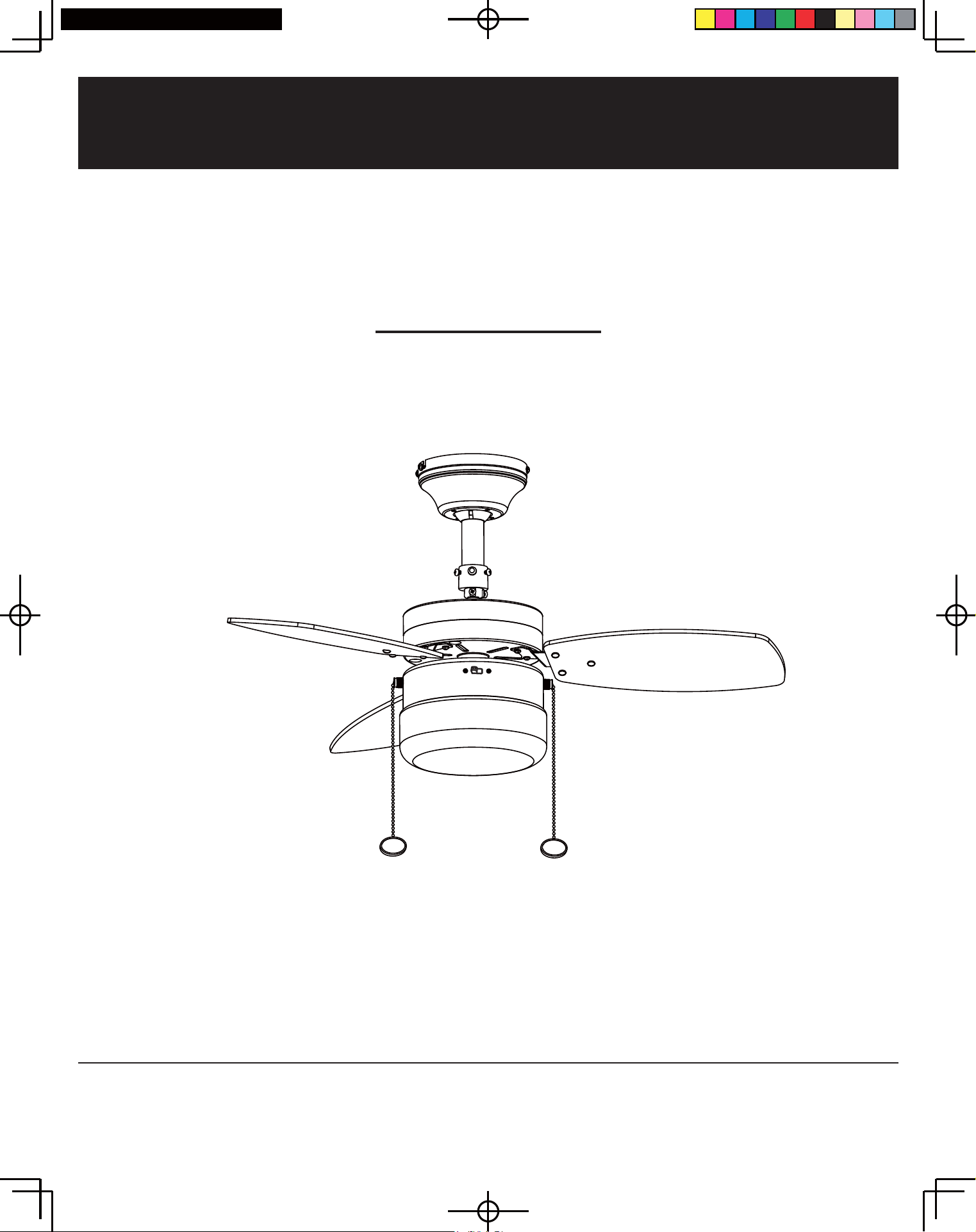
USE AND CARE GUIDE
Model# '%7%1/3'%725%/3'%7:+/3
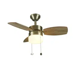
TRIPLICITY 30 IN. CEILING FAN
An electronic copy of this user manual can also be obtained online at
homedepot.com
/DB30TMB-LP/ODB30TBN-LP
Table of Contents
Table of Contents 2
Safety Information
2
Warranty
3
Operation 10
Care and Cleaning 11
Troubleshooting 11
Safety Information
PLEASE READ AND SAVE THESE INSTRUCTIONS.
.
1. To reduce the risk of electric shock, ensure electricity has been
turned off at the circuit breaker or fuse box before beginning.
2. All wiring must be in accordance with the National Electrical
Code, / , ANSI NFPA 70 and local electrical codes. Electrical
installation should be performed by a qualified licensed
electrician.
3. The outlet box and support structure must be securely mounted
and capable of reliably supporting a minimum of 35 pounds. Use
only UL Listed outlet boxes marked "FOR FAN SUPPORT."
4. Do not operate the reversing switch while the fan blades are in
motion. The fan must be turned off and blades stopped before
reversing blade direction.
5. Avoid placing objects in the path of the blades. To avoid personal
injury or damage to the fan and other items, be cautious when
working around or cleaning the fan.
6. Do not use water or detergents when cleaning the fan or fan
blades . A dry dust cloth or lightly dampened cloth will be
suitable for most cleaning.
7. After making electrical connections, spliced conductors should
be turned upward and pushed carefully up into the outlet box.
The wire should be spread apart with the grounded conductor
and the equipment-grounding conductor on one side of the
outlet box. Splices after being made should be turned upward
and pushed carefully up into the outlet box.
8. Electrical diagrams are for reference only. Light kits that are not
packed with the fan must be UL Listed and marked suitable for
use with the model fan you are installing. Switches must be UL
General Use Switches. Refer to the instructions packaged with
the light kits and switches for proper assembly.
WARNING: Before servicing or cleaning unit, switch power
off at service panel, and lock service disconnecting means to
prevent power from being switched on accidentally. When the
service disconnecting means cannot be locked, securely fasten
a prominent warning.
WARNING: To reduce the risk of fire, electric shock or
personal injury, mount to an outlet box acceptable for fan
support of 15.9 Kg (35 lbs) or less. Use mounting screws
provided with the outlet box. Most outlet boxes commonly
used for the support of lighting fixtures are not acceptable for
fan support and may need to be replaced. Consult a qualified
electrician if in doubt.
WARNING: To reduce the risk of personal injury, do not bend
the blade brackets when installing the brackets, balancing the
blades, or cleaning the fan. Do not insert foreign objects in
between rotating fan blades.
WARNING: To reduce the risk of fire or electric shock, do not
use this fan with any solid-state speed control device.
CAUTION: To reduce the risk of injury to person, the fan
must be mounted with a minimum of 7 feet clearance from the
trailing edge of the blades to the floor.
2
Specification
3
Pre-Installation 3
...................................
..................................
..........................................
........................................
.................................
................................
.......................................
Installation 5
........................................
.....................................
Tools Required
3
.....................................
Hardware Included
Package Contents
3
........................................
4
........................................
DB30TBN/ORB/WH/MB-LP, ODB30TBN-LP
RNBB-YO
WARNING: To reduce the risk of fire, electric shock or injury
to persons, do not use replacement parts that have not been
recommended by the manufacturer (e.g. parts made at home
using a 3D printer).
3
Warranty
Specification
Pre-installation
HARDWARE INCLUDED
LIMITED WARRANTY
WHAT IS COVERED
Fan Size Speed Volts Amps Watts RPM CFM N.W. G.W. C.F.
30 in.
Low 120 150
4.1 kg 0.82Med 120 200
High 120 0.32 39 280
1258
1615
2272
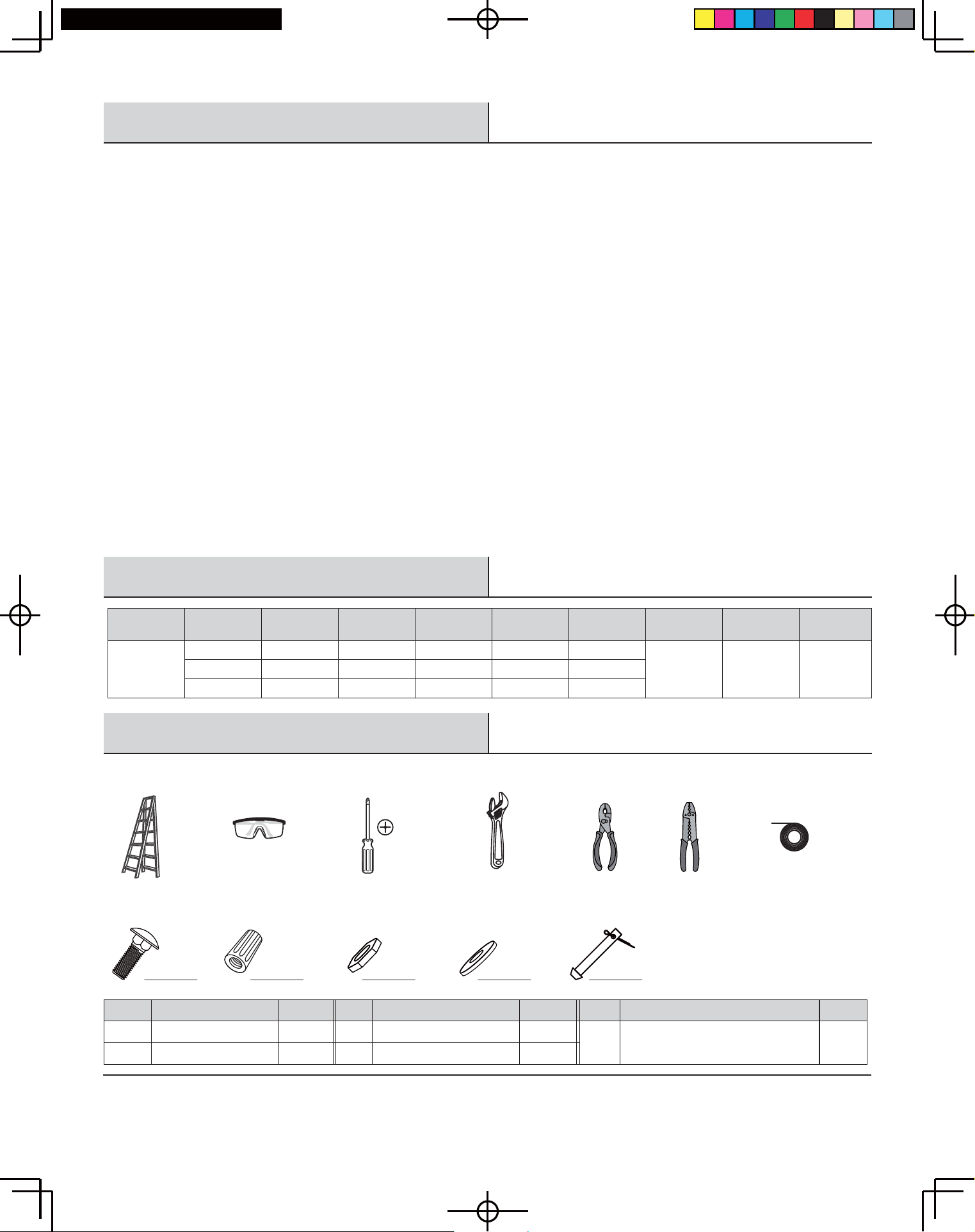
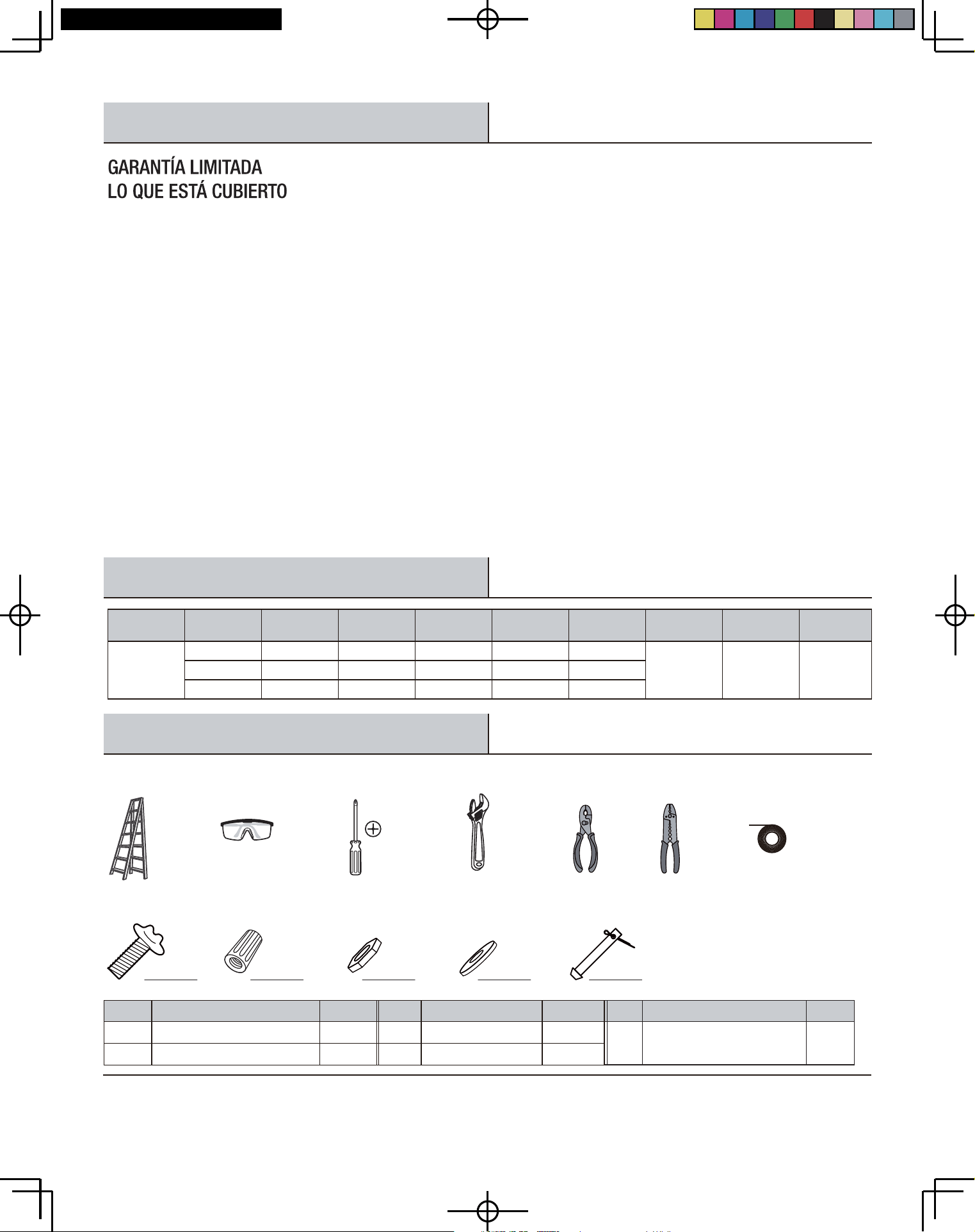
TOOLS REQUIRED
Safety
goggles
Phillips
screwdriver
Adjustable
wrench
Step
Ladder
Pliers Wire
cutter
Electrical
tape
0.29
0.28
30
32
5.42 kg
AA BB CC DD
EE
ytitnauQnoitpircseDtraP
01Square Neck ScrewsAA
01stuN eriWBB
Quantity
10
3
Part
CC
EE 1
Pivot Pin with pre-installed
Split Pin
DD
DescriptionPart ytitnauQPart DescriptionPart
Hex Nuts
Flat Washers
The retailer warrants the fan motor to be free from defects in workmanship and material present at time of shipment from the factory for
a period of fifteen years after the date of purchase by the original purchaser. The retailer warrants that the light kit, excluding any glass, to
be free from defects in workmanship and material at the time of shipment from the factory for a period of one year after the date of
purchase by the original purchaser. The retailer also warrants that all other fan parts, excluding any glass or acrylic blades, to be free from
defects in workmanship and material at the time of shipment from the factory for a period of one year after the date of purchase by the
original purchaser. We agree to correct such defects without charge or at our option replace with a comparable or superior model if the
product is returned to the retailer. To obtain warranty service, you must present a copy of the receipt as proof of purchase. All costs of
removing and reinstalling the product are your responsibility. Damage to any part such as by accident or misuse or improper installation or
by affixing any accessories, is not covered by this warranty. Because of varying climatic conditions this warranty does not cover any
changes in brass finish, including rusting, pitting, corroding, tarnishing or peeling. Brass finishes of this type give their longest useful life
when protected from varying weather conditions. A certain amount of "wobble" is normal and should not be considered a defect. Servicing
performed by unauthorized persons shall render the warranty invalid. There is no other express warranty. The retailer hereby disclaims any
and all warranties, including but not limited to those of merchantability and fitness for a particular purpose to the extent permitted by law.
The duration of any implied warranty which cannot be disclaimed is limited to the time period as specified in the express warranty. Some
states do not allow limitation on how long an implied warranty lasts, so the above limitation may not apply to you. The retailer shall not be
liable for incidental, consequential, or special damages arising out of or in connection with product use or performance except as may
otherwise be accorded by law. Some states do not allow the exclusion of incidental or consequential damages, so the above exclusion or
limitation may not apply to you. This warranty gives specific legal rights, and you may also have other rights which vary from state to state.
This warranty supersedes all prior warranties. Shipping costs for any return of product as part of a claim on the warranty must be paid by
the customer.
4
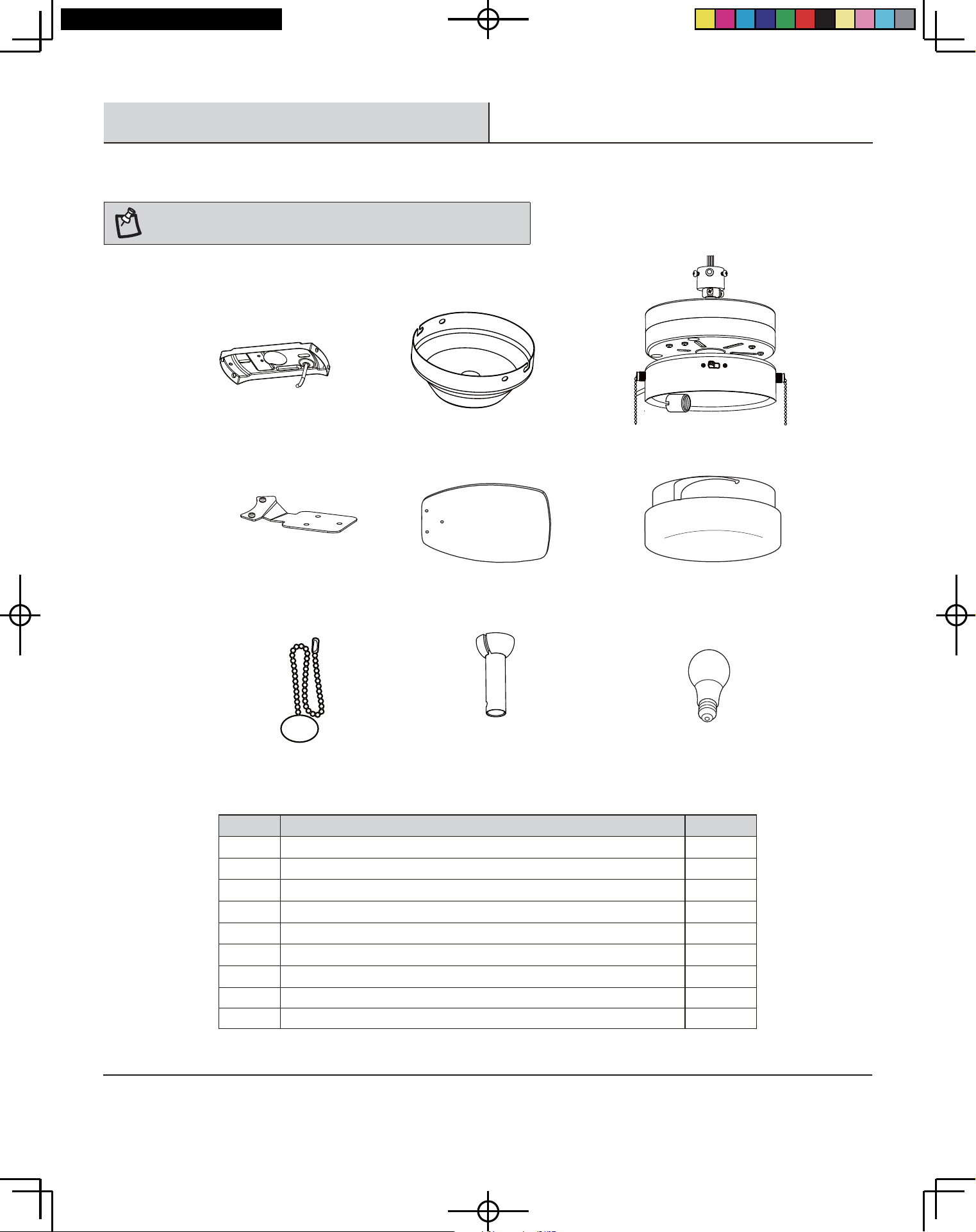
CBA
D
E
F
G
IH
ytitnauQnoitpircseDtraP
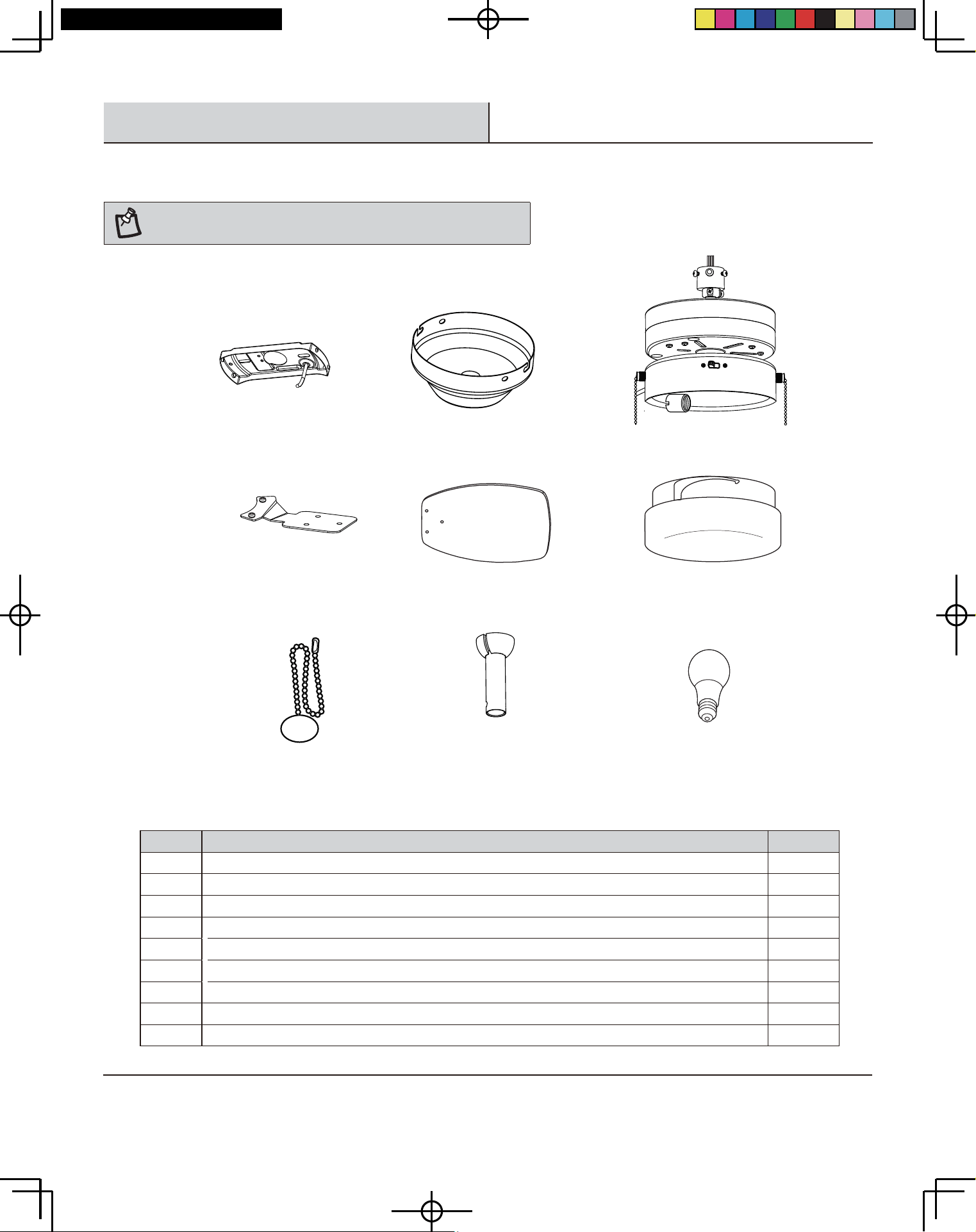
1etalp gnitnuoMA
1yponac gnilieCB
1g nisuoh hctiws htiw rotom naFC
D Set of blade holders (with blade holder screws pre-installed)
3sedalb fo teSE
1edahs ssalGF
2tnadnep niahc lluPG
3
H
½
1ylbmessA dornwoD " 4
1I
9 Watt E-26 (LED, A19) Bulb
Pre-installation (continued)
PACKAGE CONTENTS
NOTE: Unpack your fan and check the contents. You should have the
following items listed below.
DB30TBN/ORB/WH/MB-LP, ODB30TBN-LP
5
Installation
1
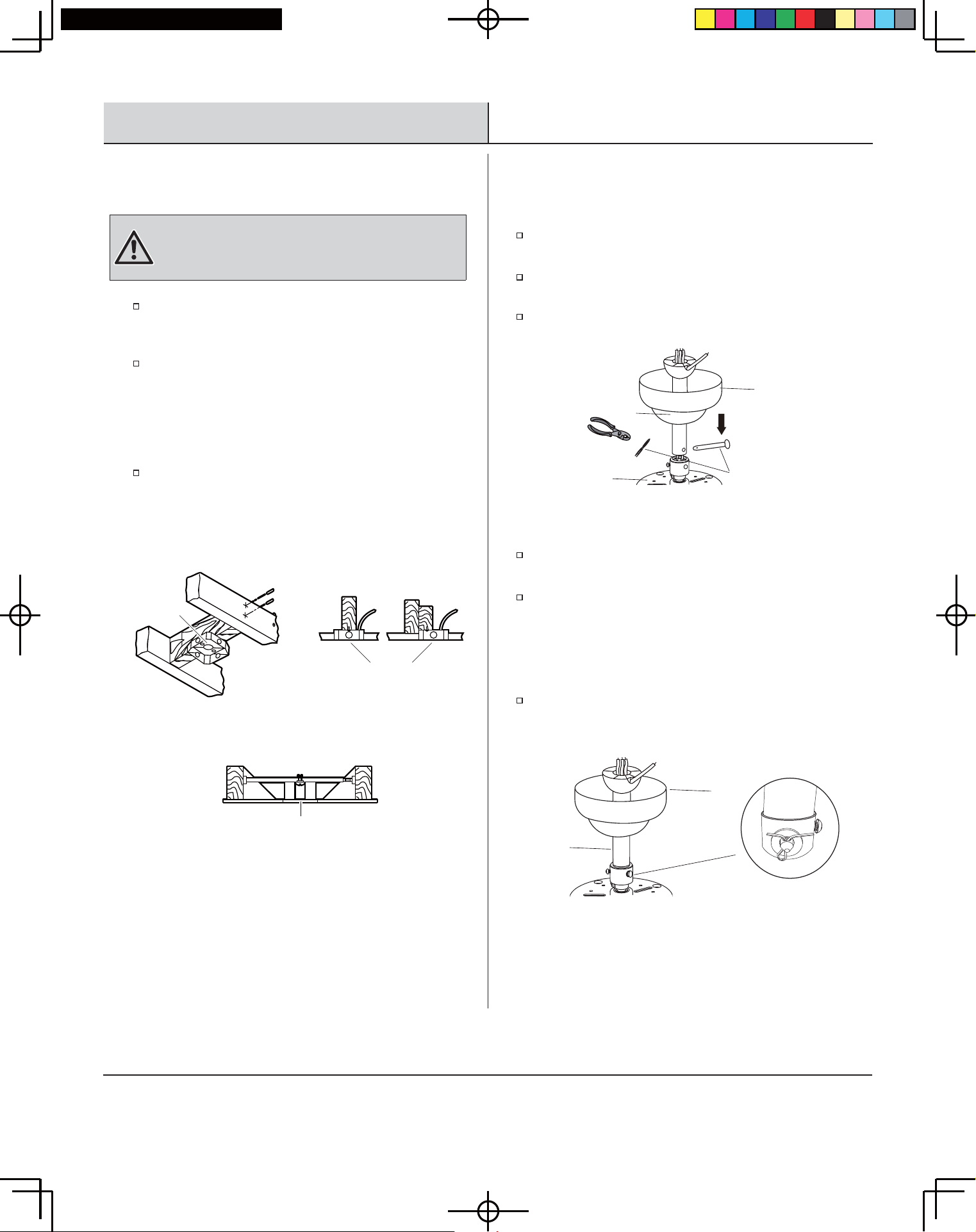
WARNING: To reduce the risk of fire, electric shock, or
personal injury, mount to outlet box marked acceptable for
fan support of 15.9 Kg (35 lbs) or less and use mounting
screws provided with the outlet box.
If there is not an existing UL Listed metal mounting box,
then read the following instructions. Disconnect the power
by removing fuses or turning off circuit breakers.
Secure the outlet box directly to the building structure. Use
appropriate fasteners and building materials. The outlet
box and its support must be able to fully support the moving
weight of the fan (at least 35 lbs.). Do not use plastic outlet
boxes. Figures 1 and 2 are examples of different ways to
mount the outlet box.
To hang your fan where there is an existing fixture but no
ceiling joist, you may need an installation hanger bar as
shown in Figure 3 (available at your Retailer).
Figure 1
Figure 2
Figure 3
Outlet Box
Outlet Box
Outlet Box
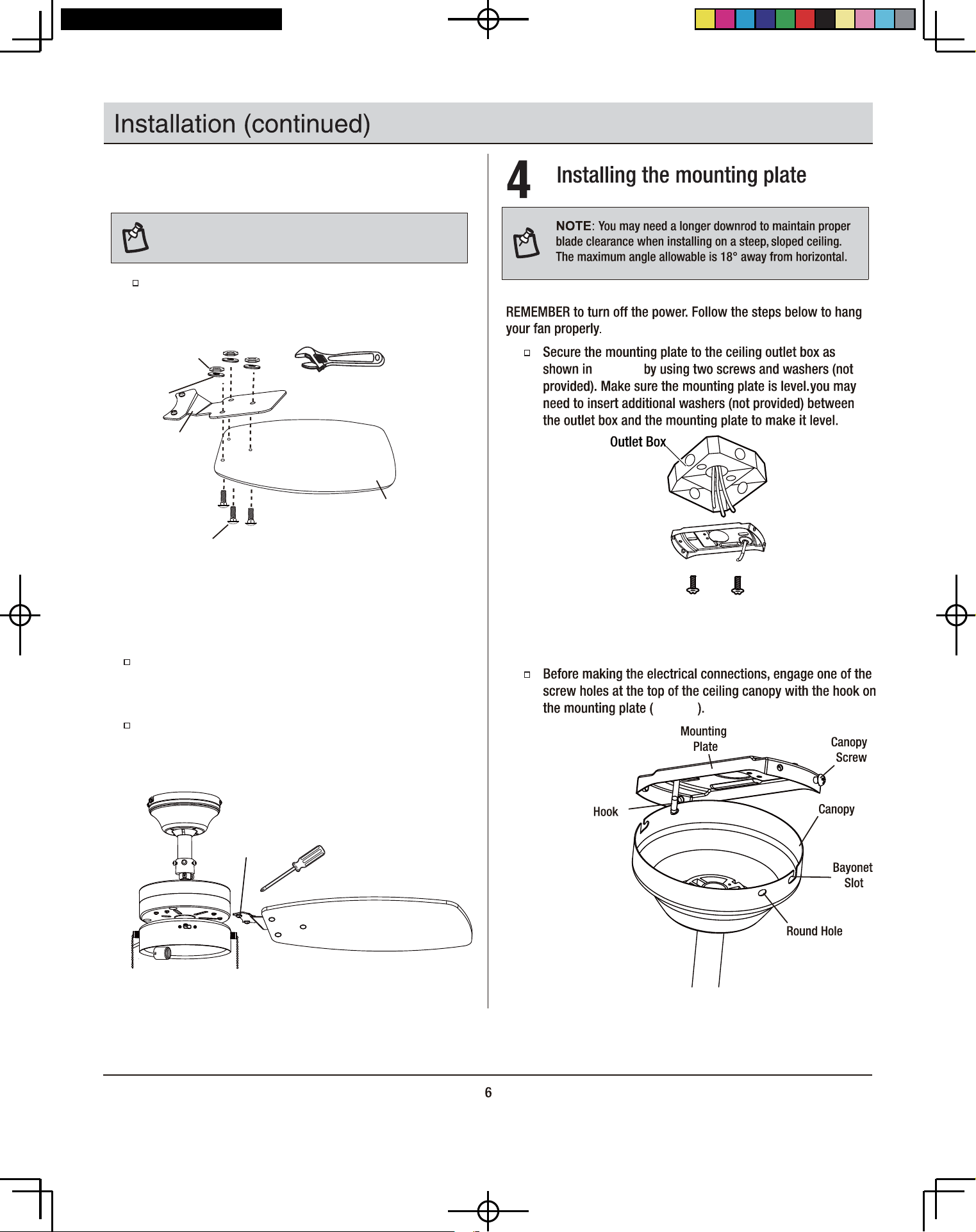
Determining mounting method Installing the fan body
2
Remove the split pin and pivot pin (EE) from the loose part bag
and set them aside for later restoration.
Place the downrod assembly (H) through the ceiling canopy
(B). (Figure 4)
Carefully feed the fan wires up through the downrod assembly
(H).
Loosen the screws first and then insert the downrod assembly
(H) into the hanger at the top of the fan motor assembly.
Secure the hanger and downrod by tightening the screws
pre-installed on the hanger (Figure 5).
Push the pivot pin (EE) through the hanger and do wnrod holes
(Figure 5). Pivot pin's insert end is a specially-designed cone
shape that pushes away and won't harm the wires inside the
downrod. Secure the pivot pin by inserting the split pin and
bending the ends to prevent it from falling out of the holes
(Figure 5).
Figure 4
Figure 5
H
B
C
EE
H
B
DB30TBN/ORB/WH/MB-LP, ODB30TBN-LP
The fan blade assemblies attach to the motor using the blade
holder screws (1) that are pre-installed into the blade holder (D).
The procedure to attach the blade assemblies is as follows:
Figure 6
Figure 8
Align the 2 pre-installed blade holder screws to the 2 holes
in the motor through the window at the bottom of the light
kit and tighten the pre-installed screws and washers.
Repeat these steps to install the remaining blade assemblies.
Attaching the fan blades
Mount the blade holders (D) to the fan blades (E) using the
square neck screws (AA), hex nuts (CC) and flat washers
(DD) provided - 3 each per blade (Figure 6).
AA
E
3
NOTE:
finish which best accentuates your decor. Failure to follow
below procedure could result in fan wobble.
Your fan blades are reversible. Select the blade side
CC
DD
D
Figure 7
1
Figure 8
Figure 9
Figure 9
5
Figure 10. Do
Figure 10
8
,QVWDOODWLRQFRQWLQXHG
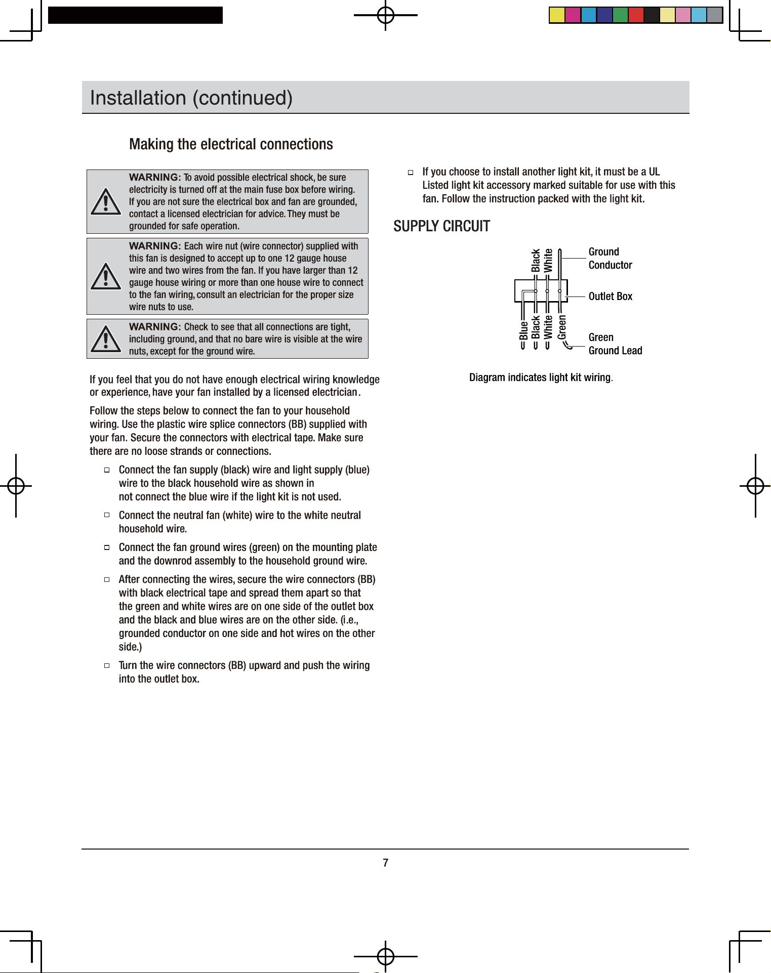
6
When the electrical connections have been
made, take the fan off the hook. Slide the ceiling
canopy up the downrod, making sure that the
ball joint groove engages with the ceiling canopy
entry hole tab. Slide the bayonet slots on the
ceiling canopy onto the screws at either end of
the mounting plate, secure with the four screws
provided (Figure 11).
Figure 11
Finishing the installation
Downrod
Ceiling
Canopy
Bayonet
Locating Slot
Screw
Hole
Mounting
Plate
Groove
Tab
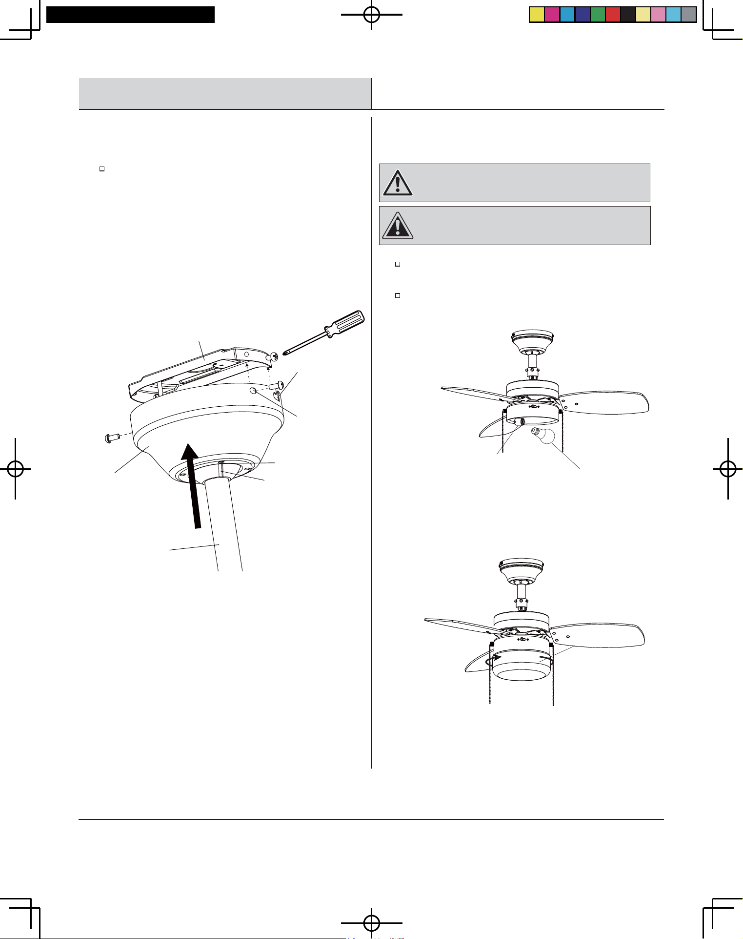
DB30TBN/ORB/WH/MB-LP, ODB30TBN-LP
Install a light bulb (max. 9W, LED, medium screw base) to
e 12 ).
Install the lamp shade (F) into the lamp-fitter by a gentle
clockwise twist-and-lock (Figure 13 ).
Installing the light kit
7
the lampholder (Figur
WARNING: To reduce the risk of electric shock ,
disconnect the electrical supply circuit to the fan before
installing light kit.
CAUTION: Glass is fragile and delicate, handle with care.
Overtightening of glass shade may crack it.
Figure 12
Figure 13
Light Bulb
Lamp Holder
F
,QVWDOODWLRQFRQWLQXHG
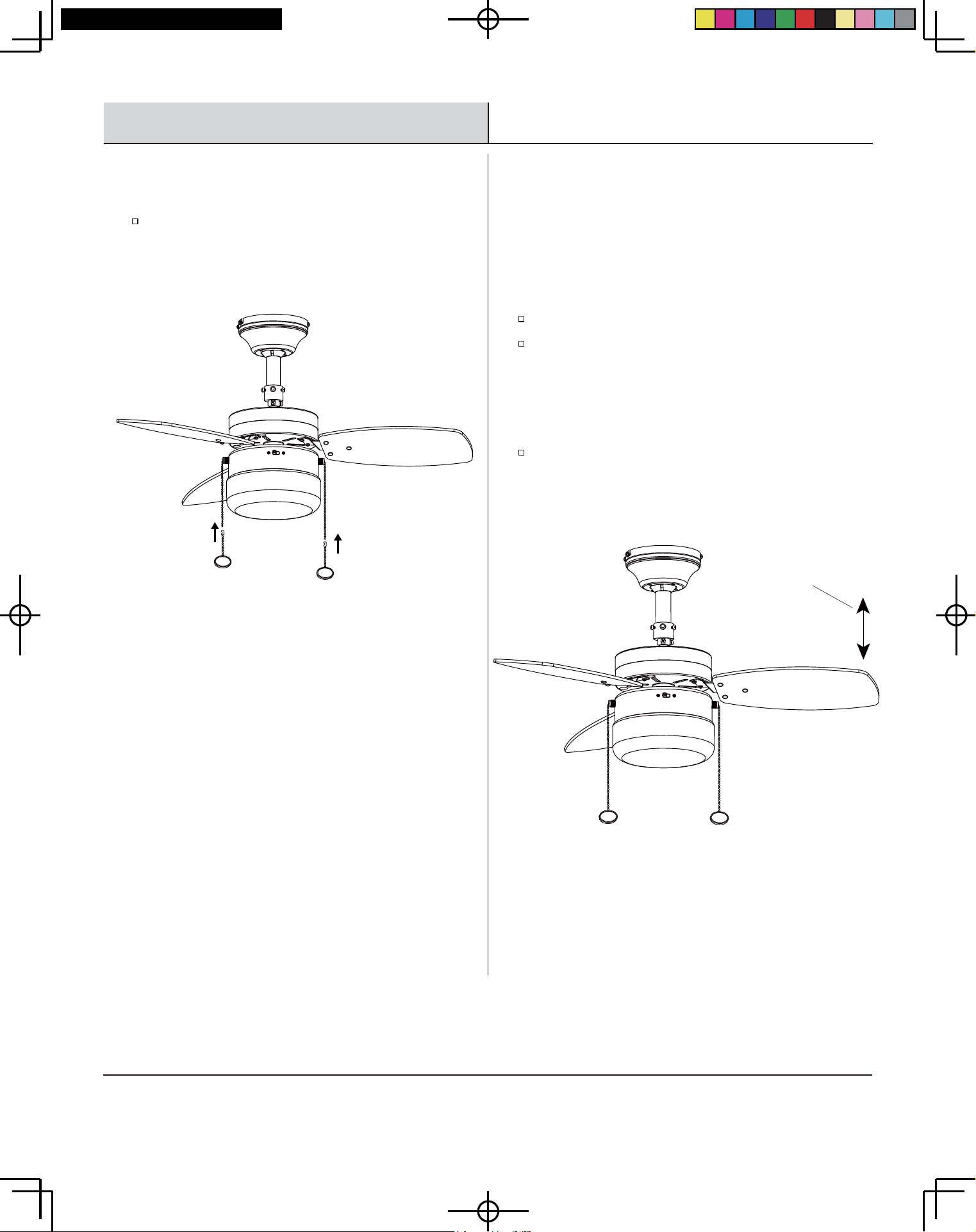
9
Attached the pull chain extensions (G) provided to the fan
and light kit pull chain. (Figure 14)
Attaching the pull chain extensions
8
Figure 14
density, the fan may wobble even though the blades are weight
matched.
The following procedure should correct most fan wobble. Check for
wobble after each step.
Check that all blade and blade holder screws are secure.
Most fan wobble problems are caused when blade levels
are unequal. Check this level by selecting a point on the
ceiling above the tip of one of the blades. Measure this
eht litnu naf eht etatoR . 51 erugiF ni nwohs sa ecnatsid
next blade is positioned for measurement. Repeat for each
blade. Measurements should be within 1/8 in.
If blade wobble is still noticeable, interchanging two
adjacent (side by side) blades can redistribute the weight
and possibly result in smoother operation.
Balancing the blades
All blades are grouped by weight. Because natural woods vary in
9
Figure 15
Touch Ceiling
10
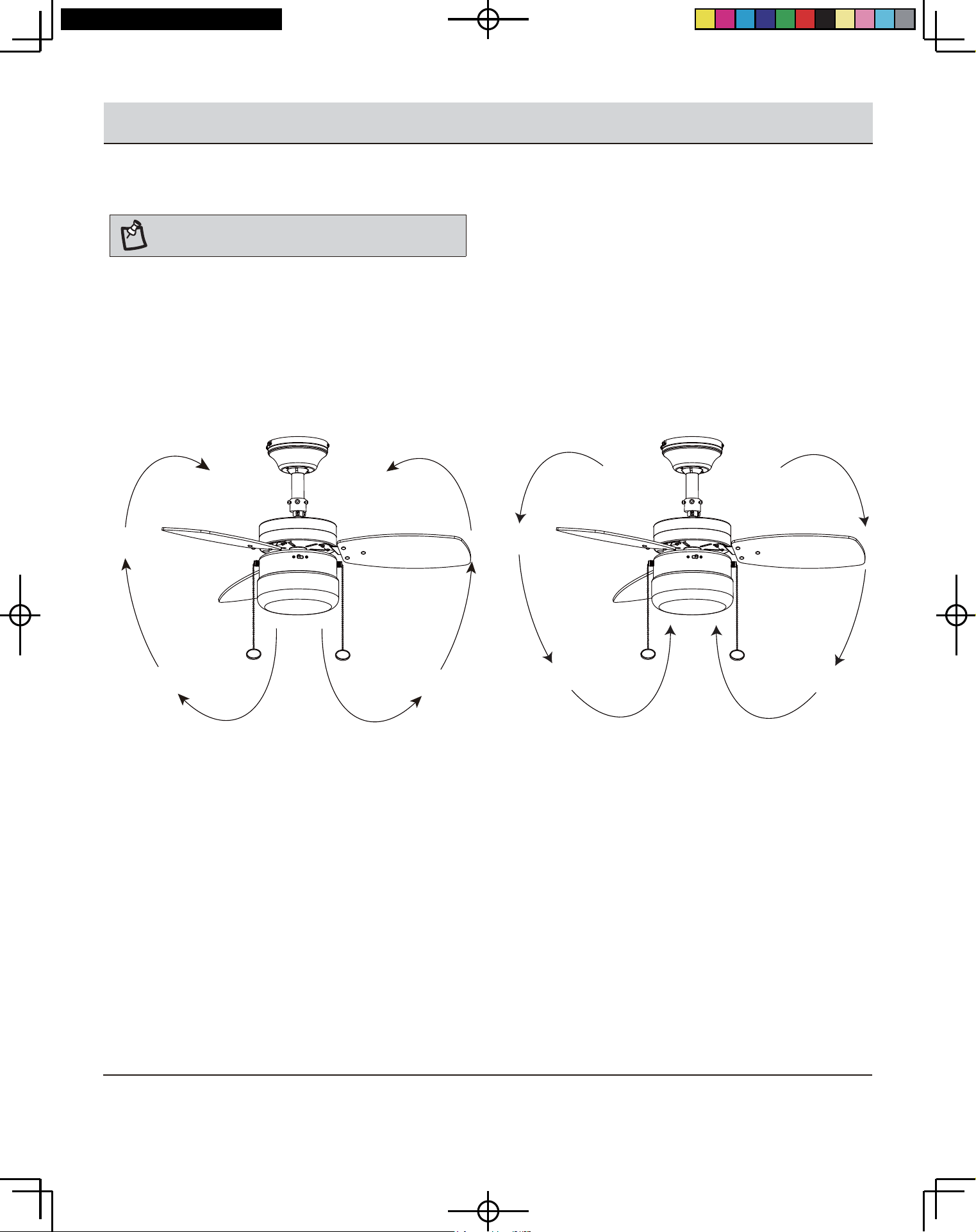
2SHUDWLRQ
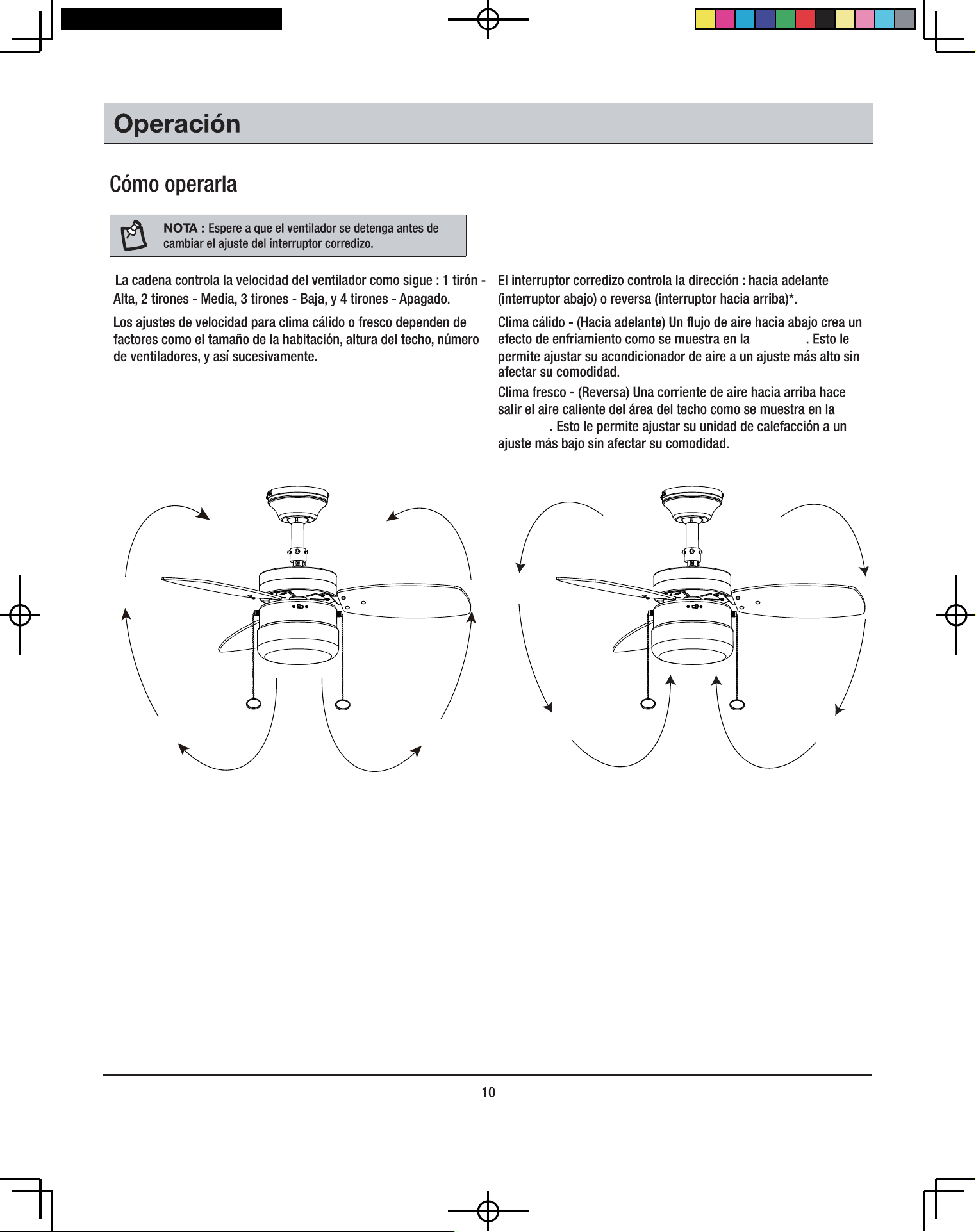
pulls - Medium, 3 pulls – Low, and 4 pulls – off.
Speed settings for warm or cool weather depend on factors such
as the room size, ceiling height, number of fans, and so on.
The slide switch controls direction: forward (switch down) or
reverse (switch up).*
Warm weather - (Forward) A downward air flow creates a cooling
effect as shown in Figure 15 . This allows you to set your air
conditioner on a higher setting without affecting your comfort.
Cool weather - (Reverse) A n upward air flow moves warm air off
the ceiling area as shown in Figure 16 . This allows you to set your
heating unit on a lower setting without affecting your comfort.
The pull chain controls the fan speed as follows: 1 pull – High, 2
Operating
*NOTE: Wait for the fan to stop before changing the setting
of the slide switch.
DB30TBN/ORB/WH/MB-LP, ODB30TBN-LP
Figure 15
Figure 16
11
Care and Cleaning
WARNING: Make sure the power is off at the electrical panel box before you attempt any repairs. Refer to the section Making Electrical
Connections Section.
Because of the fan's natural movement, some connections may become loose. Check the support connections, brackets, and blade
attachments twice a year. Make sure they are secure. (It is not necessary to remove the fan from the ceiling.)
Clean your fan periodically to help maintain its new appearance over the years. Use only a soft brush or lint-free cloth to avoid
scratching the finish. The plating is sealed with a lacquer to minimize discoloration or tarnishing. Do not use water when cleaning. This
could damage the motor, or the wood, or possibly cause an electrical shock.
You can apply a light coat of furniture polish to the wood blades for additional protection and enhanced beauty. Cover small scratches
with a light application of shoe polish.
There is no need to oil your fan. The motor has permanently lubricated bearings.
Troubleshooting
WARNING: Make sure the power is off at the electrical panel box before you attempt any repairs. Refer to the section Making Electrical
Connections Section.
Problem Solution
The fan will not start. Check circuit fuses or breakers.
Check the line wire connections to the fan and switch wire connections in the switch housing.
The fan sounds noisy. Make sure all motor housing screws are snug.
Make sure the screws that attach the fan blade bracket to the motor hub are tight.
Make sure wire nut connections are not rubbing against each other or the interior wall of the switch
housing.
Allow a 24-hour "breaking-in period. Most noises associated with a new fan disappear during this time".
Some fan motors are sensitive to signals from solid-state variable speed controls. If you have installed
this type of control, choose and install another type of control.
Make sure the motor housing is a short distance from the ceiling. It should not touch the ceiling.
Here are some suggestions to help you maintain your fan.
An electronic copy of this user manual can also be obtained online at
homedepot.com
Retain this manual for future use.
Núm. de modelo
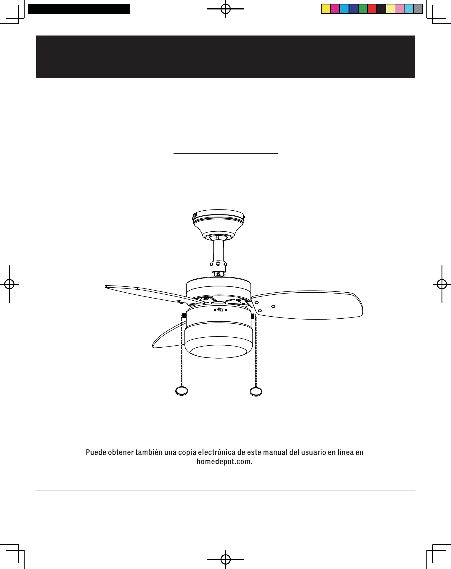
VENTILADOR DE TECHO TRIPLICITY DE 30 PLUG.
'%7%1/3'%725%/3'%7:+/3
GUÍA DE USO Y CUIDADO
/DB30TMB-LP/ODB30TBN-LP
DB30TBN/ORB/WH/MB-LP, ODB30TBN-LP
RNBB-YO
ADVERTENCIA: Para reducir el riesgo de incendio
descarga eléctrica o lesiones personales, no utilice piezas de
repuesto que no hayan sido recomendadas por el fabricante
(por ejemplo, piezas fabricadas en casa con una impresora 3D).
3
Garantía
Especificaciones
Tamaño del
ventilador
Velocidad Voltios Amperios Watts tr/min
3
pies /min Peso neto Peso bruto C.F.
30 plug
8521051021ajaB
5161002021aideM
Alta 120 0.32 39 280 2272
Pre-instalación
HERRAJES INCLUIDOS
Gafas de
seguridad
Destornillador
Phillips
Llave
ajustable
Escalera
de tijera
Alicate Cortador
de
alambre
Cinta de
electricista
HERRAMIENTAS REQUERIDAS
0.29
0.28
30
32
4.1 kg 0.825.42 kg
EE 1
Pasador pivotante con
clavija partida preinstalada
ytitnauQDescriptionPart
Pieza Descripción Cantidad
AA Tornillos de la hoja 10
BB Tuercas de cable 3
Pieza
CC
DD
Descripción
Tuercas hexagonales
Arandelas planas
Cantidad
10
10
AA BB CC DD
EE
El distribuidor garantiza que el motor del ventilador está libre de defectos en materiales y mano de obra presentes en el momento del envío
de la fábrica por un periodo de quince años después de la fecha de compra por el comprador original. El distribuidor garantiza, por un período
de un año a partir de la fecha de adquisicion por le comprador original, que el kit de luces, sin incluir ningun vidrio, no presentará ningún
defecto de fabricación o de material desde el momento de su salida de la fábrica. El distribuidor también garantiza que todas las demás
piezas del ventilador, excepto las aspas de vidrio o acrílico, no tienen defectos de mano de obra ni de materiales en el momento del envío
desde la fábrica durante un período de un año a partir de la fecha de compra por parte del comprador original. Aceptamos corregir
cualquier defecto sin cargos o a nuestra discreción reemplazar con un modelo comparable o superior si el producto es devuelto a el
distribuidor. Para obtener el servicio de garantía, debe presentar una copia del recibo como prueba de compra. Todos los costos por retirar
o reemplazar el producto son su responsabilidad. Los daños a cualquier pieza por accidente o mal uso o instalación inapropiada o por la
fijación de cualquier accesorio, no están cubiertos por la garantía. Debido a las condiciones climáticas variables, esta garantía no cubre
ningún cambio en el acabado de latón, incluyendo herrumbre, picaduras, corrosión, deslustrado o descamación. Los acabados de latón de
este tipo dan su vida útil más larga cuando se protegen de las condiciones climáticas variables. Es normal una cierta cantidad de
"bamboleo" y no debe ser considerado un defecto. El mantenimiento realizado por personas no autorizadas anulará la garantía. No hay otra
garantía expresa. Por la presente, el distribuidor renuncia a cualquier y todas las garantías, incluyendo pero no limitadas a Garantías de
comercialización o idoneidad para un propósito particular en la medida permitida por la ley. La duración de cualquier garantía implícita que
no puede ser denegada está limitada al periodo de tiempo que se especifca en la garantía expresa. Algunos estados no permiten limitaciones
sobre cuánto debe durar una garantía implícita, por lo tanto las limitaciones anteriores podrían no aplicar a usted. La tienda minorista no será
responsable de daños incidentales, consecuenciales, o daños especiales que surgan de o con respecto al uso o rendimiento del producto
excepto como pueda ser acordado de otra manera por la ley. Algunos estados no permiten la exclusión de los daños incidentales o
consecuenciales, por lo tanto, las limitaciones y exclusiones anteriores podrían no aplicar a usted. Esta garantía le otorga derechos legales
específicos y también puede tener otros derechos que varían de un estado a otro. Esta garantía reemplaza todas las garantías anteriores.
Pre-instalación (continuación)
4
daditnaCnóicpircseDazeiP
1ejatnom ed acalPA
1
1
ohcet led atreibuCB
rotpurretni ed asacrac noc rodalitnev led rotoMC
D Conjunto de soportes de las aspas (con tornillos de soportes de las aspas preinstalados)
3sapsa ed otnujnoCE
1 arapmál al ed allatnaPF
2
3
anedac ed etnagloc rodalaHG
H
½
1arav al ed dadinu " 4
I 1
Foco de 9 Watts de base E-26 (LED, A19)
CONTENIDO DEL PAQUETE
NOTA : Desempaque su ventilador y compruebe el contenido. Debe tener
los siguientes artículos listados a continuación.
DB30TBN/ORB/WH/MB-LP, ODB30TBN-LP
BA
D
E
F
G
IH
C
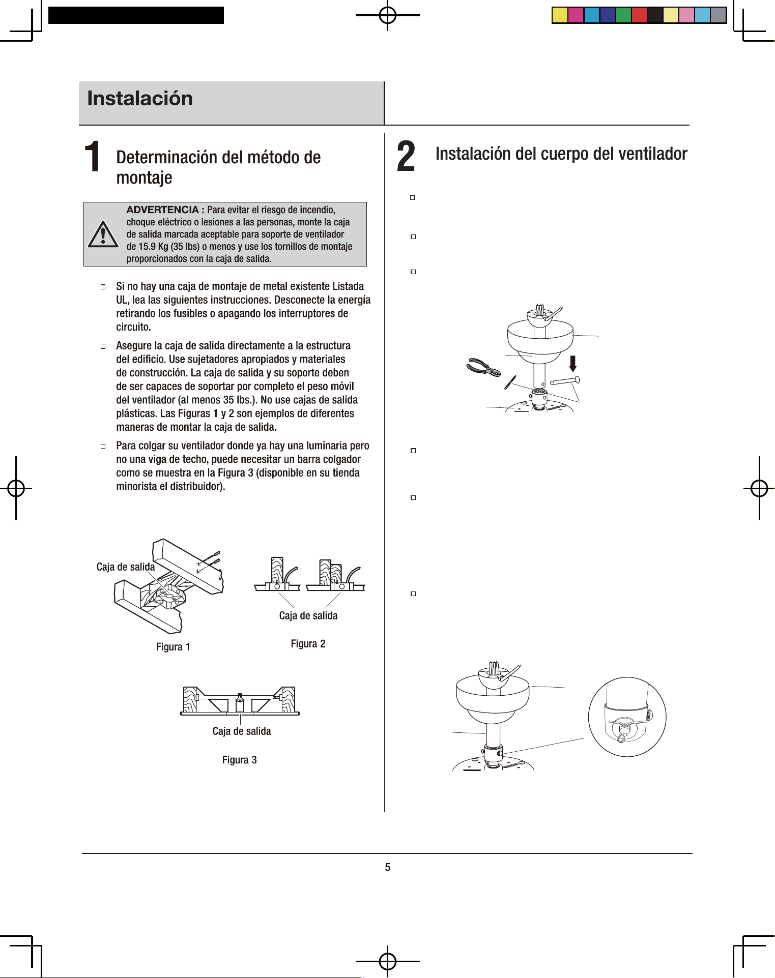
Figura 5
H
B
C
EE
H
B
Saque el pasador partido y el pasador pivotante (EE) de la
bolsa de piezas sueltas y apártelos para su posterior
restauración.
Coloque la unidad de la vara (H) a través de la cubierta del
techo (B) (Figura 4).
Pase con cuidado los cables del ventilador por el conjunto
del vástago (H).
Afloje los tornillos primero y luego inserte el conjunto de la
varilla de extensión (H) en la barra de suspensión en la parte
superior del conjunto del motor del ventilador.
Asegure la barra de suspensión y la varilla de extensión
ajustando los tornillos instalados previamente en la barra de
suspension (Figura 5).
Empuje el pasador (EE) a través del eje del motor y de los o
rificios de la vara (Figura 5). El extremo de inserción del
pasador pivotante tiene una forma cónica especialmente
diseñada que se aleja y no daña los cables del interior del
vástago. Asegure el pasador insertando el pasador de
chaveta y doblando los extremos para evitar que se salga de
los orificios (Figura 5).
Figura 4
DB30TBN/ORB/WH/MB-LP, ODB30TBN-LP
34
Instalación de las aspas del
ventilador
Monte los soportes de las aspas (D) a las aspas del
ventilador (E) con los tornillos de cuello cuadrado (AA), las
tuercas hexagonales (CC) y las arandelas planas (DD)
incluidas (3 por cada aspa) (Figura 6).
Los conjuntos de las hojas del ventilador deben conectarse al motor
usando los tornillos de los soportes de las hojas (1) instalados
previamente en el soporte de las hojas (D). El procedimiento para
conectar los conjuntos de las hojas es el siguiente:
Alinee los 2 tornillos del soporte de la cuchilla previamente
instalados con los 2 agujeros en el motor a través de la
ventana en la parte inferior del kit de luces y ajuste los
tornillos y arandelas previamente instalados.
Repita estos pasos para instalar los ensamblajes de las
aspas restantes.
NOTA :
Seleccione el acabado lateral del aspa que mejor acentúe su
decoración. No seguir el procedimiento anterior puede
resultar en bamboleo del ventilador.
Las aspas de su ventilador son reversibles.
Figura 6
Figura 7
Figura 8
Figura 8
Figura 9
Figura 9
AA
E
CC
DD
D
1
5
Figura 10
Figura 10
Conecte los cables de conexión a tierra del ventilador (verde)
en la placa de montaje; y la unidad de la vara con el cable de
conexión a tierra de la conexión del hogar.
8
Instalación (continuación)
76
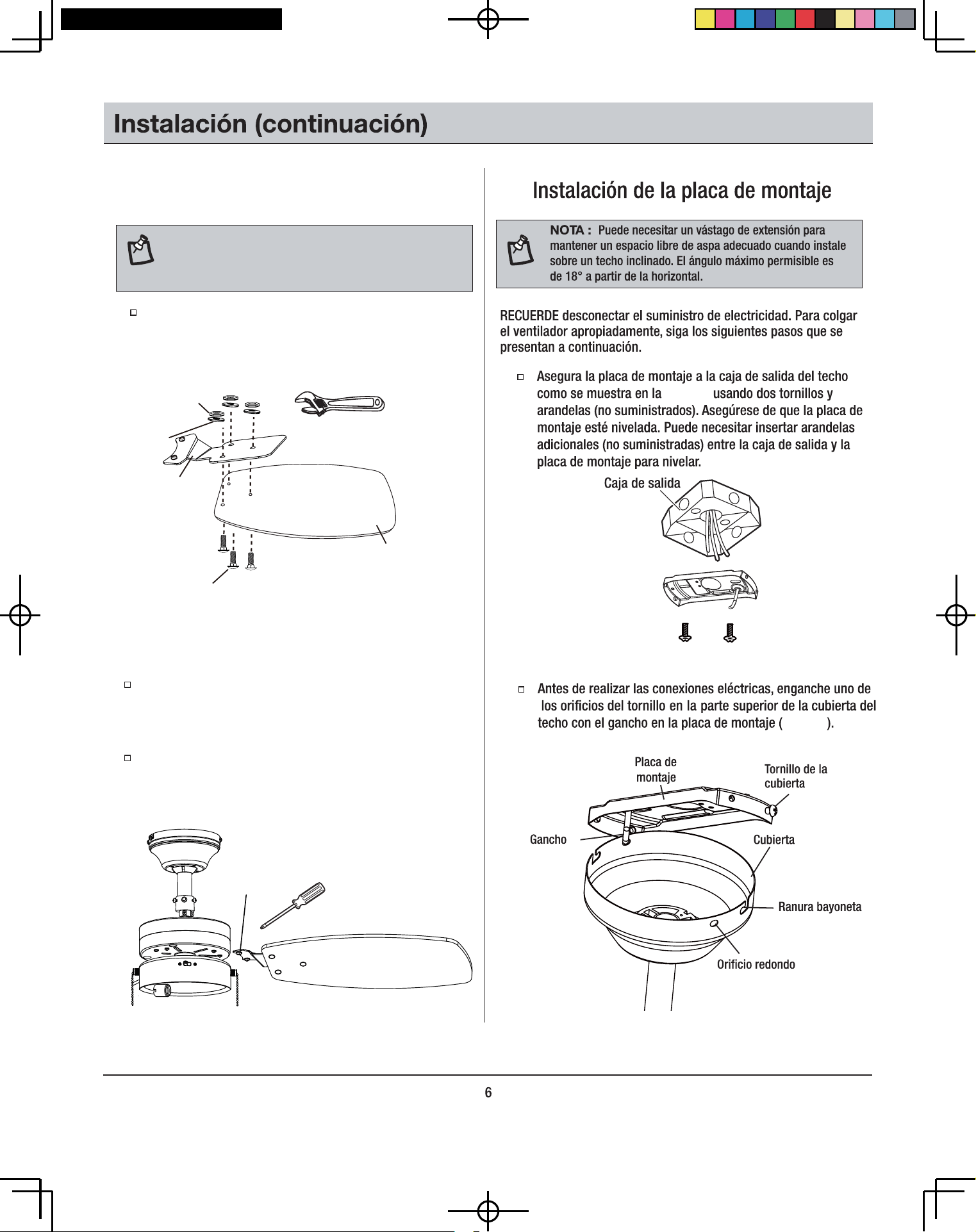
Una vez realizadas las conexiones eléctricas, quite
el ventilador del gancho. Deslice la cubierta del techo
hacia arriba de la vara, asegurándose de que la ranura
de la junta de rótula se enganche con la lengüeta de
orificio de entrada de la cubierta del techo. Deslice las
ranuras bayoneta en la cubierta del techo, sobre los
tornillos en cada extremo de la placa de montaje y
asegúrelas con los cuatro tornillos incluidos (Figura 11).
Finalización de la instalación
Figura 11
Orificio para tornillo
Placa de
montaje
Unidad de la vara
Ranura
Lengüeta
Ranura bayoneta
de ubicación
Cubierta del
techo
DB30TBN/ORB/WH/MB-LP, ODB30TBN-LP
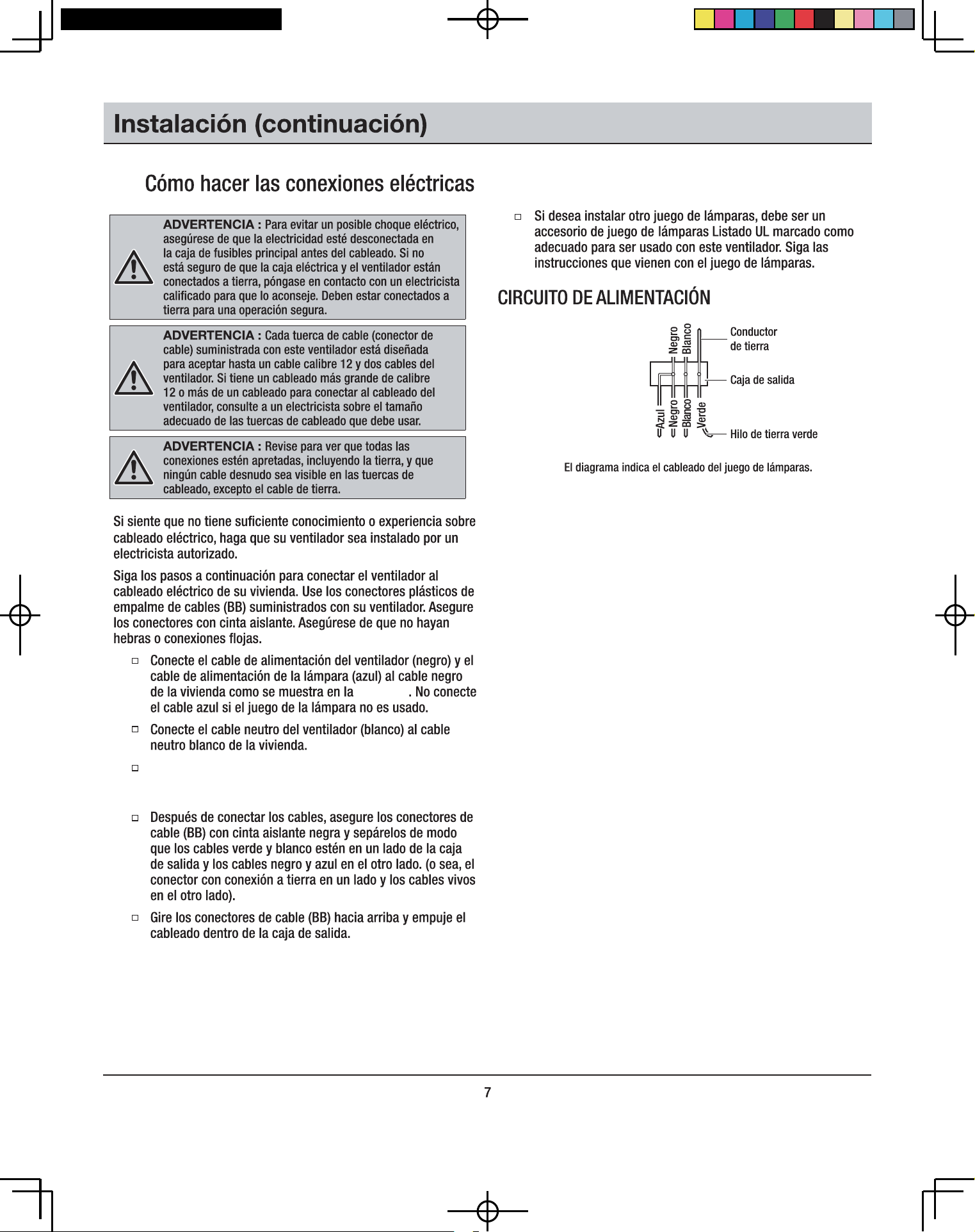
Instalación del juego de lámparas
Coloque la pantalla de la lámpara (F) en el ajustador de la
lámpara mediante un suave giro y ajuste en sentido horario
(Figura 12).
Figura 12
Bombilla
Portalámpara
Figura 13
Coloque una bombilla de luz (9 W máx., LED, base enroscable
mediana) al portalámpara (Figura 12).
ADVERTENCIA : Para reducir el riesgo de choque
eléctrico, desconecte el circuito de suministro eléctrico al
ventilador antes de instalar el juego de lámparas.
PRECAUCIÓN : El vidrio es frágil y delicado, trátelo con
cuidado. El sobreajuste de la pantalla de la lámpara puede
quebrarla.
F
9
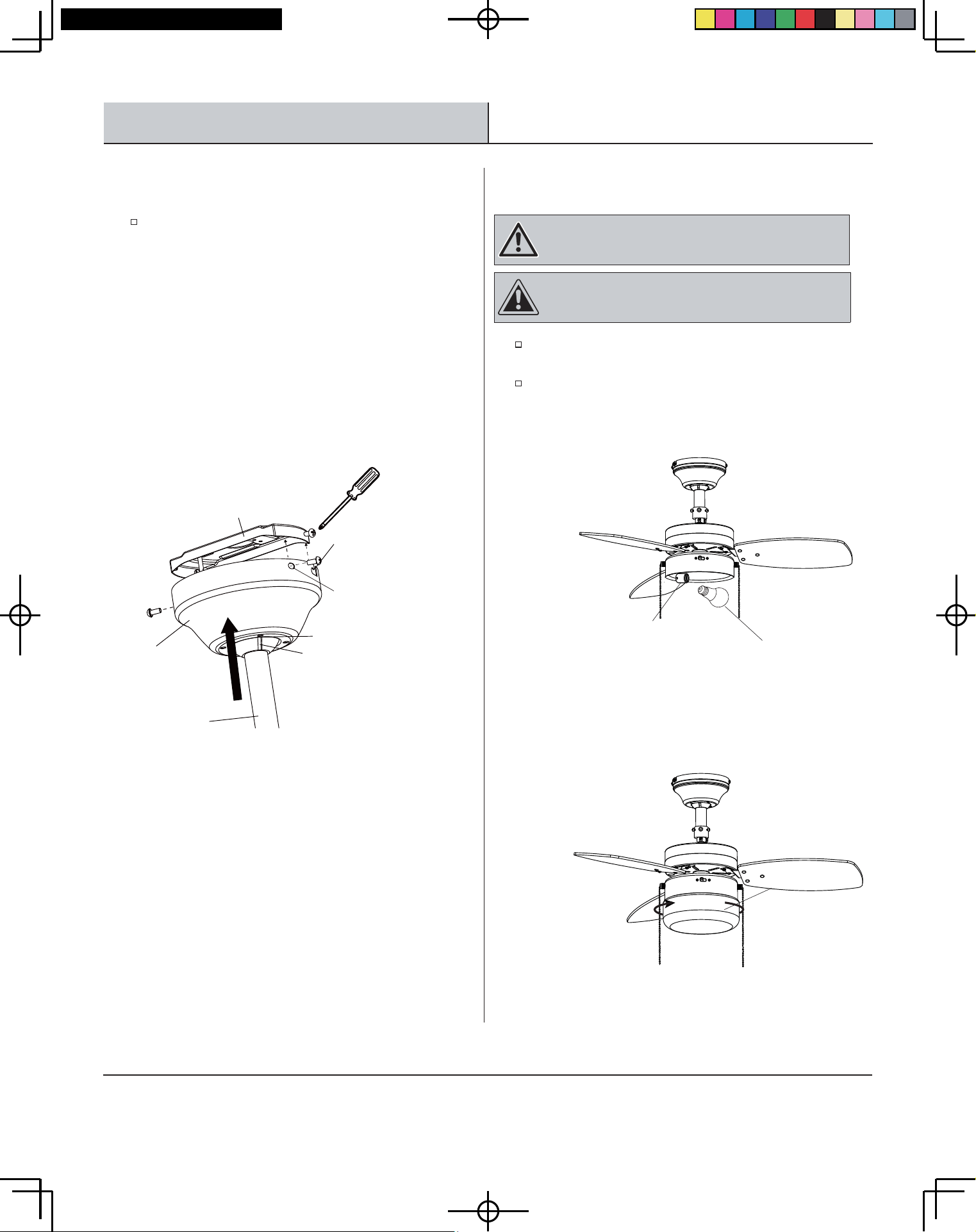
Cómo instalas las extensiones de
cadena del interruptor
8
Figura 14
Instalación (continuación)
Conecta las extensiones de cadena de interruptor (G)
suministradas a las cadenas de los interruptores del ventilador y
la luz.
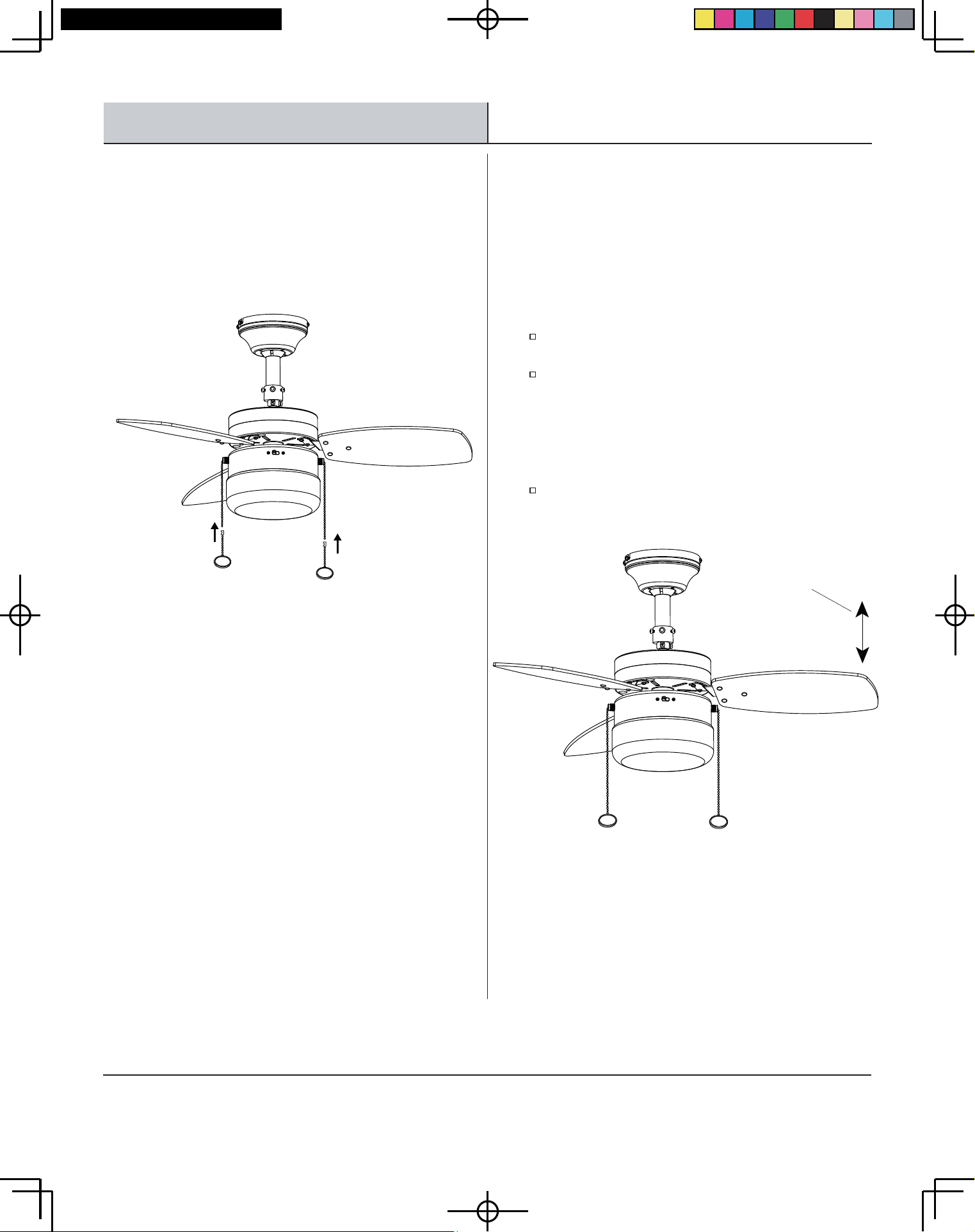
Cómo equilibrar las aspas
9
maderas naturales varían en densidad, el ventilador puede
bambolear incluso si las aspas concuerdan en peso.
El siguiente procedimiento debe corregir la mayor parte del
bamboleo del ventilador. Compruebe si hay bamboleo después de
cada paso.
Compruebe que todos los tornillos de las aspas y soportes
las aspas estén seguros.
La mayoria de problemas de bamboleo ocurren cuando los
niveles de las aspas son desiguales. Compruebe este nivel
seleccionando un punto en el techo sobre la punta de una
de las aspas. Mida esta distancia como se muestra en la
Figura 15. Gire el ventilador hasta que la siguiente aspa
esté ubicada para medición. Repita para cada aspa. Las
medidas deben estar dentro de 1/8 plug.
Si todavía se nota bamboleo en el aspa, el intercambio de dos
aspas adyacentes (lado por lado) puede redistribuir el peso y
posiblemente resulte en un funcionamiento más estable.
Figura 15
Todas las aspas están agrupadas por peso. Debido a que las
Tocar techo
DB30TBN/ORB/WH/MB-LP, ODB30TBN-LP
Figura 15 Figura 16
Figura 15
Figura 16
11
Cuidado y limpieza
ADVERTENCIA : Asegúrese de que la energía esté desconectada en la caja del panel eléctrico antes de intentar cualquier reparación.
Consulte la sección Cómo Hacer Conexiones Eléctricas.
Debido al movimiento natural del ventilador, algunas conexiones se pueden aflojar. Revise las conexiones del soporte, soportes y
acoplamientos de las aspas dos veces al año. Asegúrese de que estén seguras. (No es necesario retirar el ventilador del techo.)
Limpie su ventilador periódicamente para ayudar a mantener su apariencia nueva con el paso de los años. Use solamente un cepillo
suave o paño sin pelusa para evitar rayar el acabado. El enchapado está sellado con una laca para minimizar la decoloración o el
deslustrado. No use agua cuando limpie. Esto podría dañar el motor, o la madera, o causar posiblemente un choque eléctrico.
Puede aplicar una capa ligera de cera para muebles a las aspas de madera para protección adicional y belleza mejorada. Cubra las
rayas pequeñas con una aplicación ligera de betún para calzado.
No hay necesidad de aceitar su ventilador. El motor tiene cojinetes lubricados permanentemente.
Solución de problemas
ADVERTENCIA : Asegúrese de que la energía esté desconectada en la caja del panel eléctrico antes de intentar cualquier reparación.
Consulte la sección Cómo Hacer Conexiones Eléctricas.
Problema Solución
El ventilador no arranca. Revise los fusibles o los interruptores.
Revise las conexiones del cable de línea al ventilador y las conexiones del cable del interruptor en la
carcasa del interruptor.
El ventilador hace ruido. Asegúrese de que todos los tornillos de la carcasa del motor estén ajustados.
Asegúrese de que los tornillos que sujetan el soporte del aspa del ventilador al núcleo del motor estén
apretados.
Asegúrese de que las conexiones de la tuerca del cable no rocen entre sí o con la pared interior de la
carcasa del interruptor.
Permita un periodo de "rodaje" de 24 horas. La mayoría de ruidos asociados a un ventilador nuevo
desaparecen durante este tiempo.
Algunos motores de ventilador son sensibles a señales de controles de velocidad variable de estado
sólido. Si tiene instalado este tipo de control, elija e instale otro tipo de control.
Asegúrese de que la carcasa del motor esté a una corta distancia del techo. No debe tocar el techo.
Aquí tiene algunas sugerencias para ayudarle a mantener su ventilador.
Puede obtener también una copia electrónica de este manual del usuario en línea en
homedepot.com.
Conserve este manual para uso futuro.