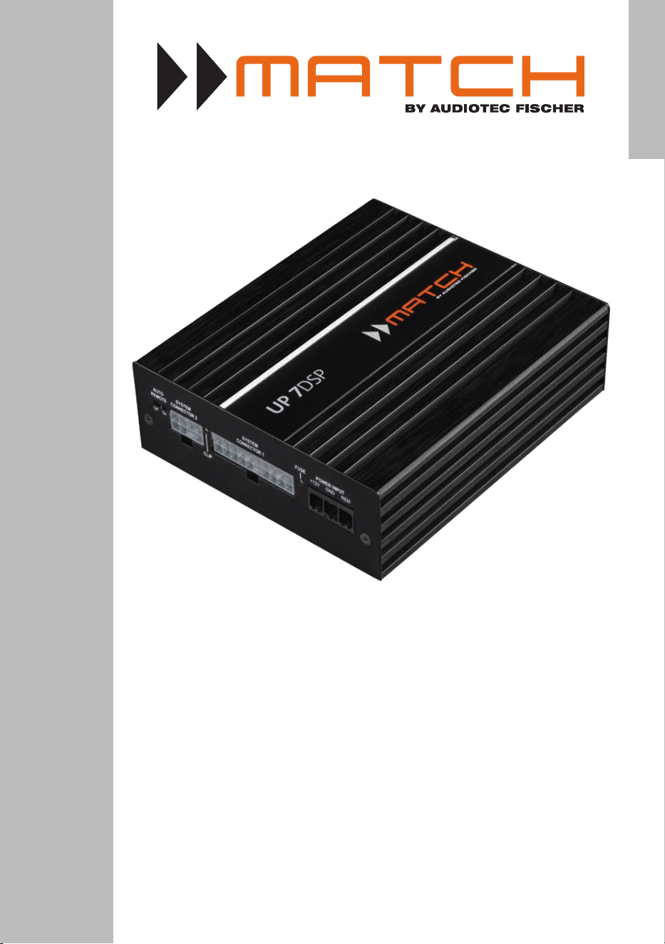
UP 7DSP
UPGRADE
7-Kanal Upgrade-Verstärker mit integriertem 8-Kanal
64 Bit DSP für universelle Anwendungen
7-channel upgrade amplier with integrated 8-channel
64 Bit DSP for universal applications
deutsch / english

2
Sehr geehrter Kunde,
wir gratulieren Ihnen zum Kauf dieses hochwertigen
MATCH Verstärkers mit integriertem DSP.
MATCH setzt mit dem UP 7DSP neue Maßstäbe im
Bereich der Verstärkertechnik. Dabei protieren Sie
als Kunde direkt von unserer mehr als 30-jährigen
Erfahrung in der Forschung und Entwicklung von
Audiokomponenten.
Dieser Upgrade-Verstärker wurde von uns nach
neuesten technischen Erkenntnissen entwickelt und
zeichnet sich durch hervorragende Verarbeitung
und eine überzeugende Anwendung ausgereifter
Technologien aus.
Viel Freude an diesem Produkt wünscht Ihnen das
Team von
AUDIOTEC FISCHER
Allgemeines zum Einbau von MATCH-Kompo-
nenten
Um alle Möglichkeiten des Produktes optimal aus-
schöpfen zu können, lesen Sie bitte sorgfältig die
nachfolgenden Installationshinweise. Wir garantie-
ren, dass jedes Gerät vor Versand auf seinen ein-
wandfreien Zustand überprüft wurde.
Vor Beginn der Installation unterbrechen Sie
den Minusanschluss der Autobatterie.
Wir empfehlen Ihnen, die Installation von einem
Einbauspezialisten vornehmen zu lassen, da der
Nachweis eines fachgerechten Einbaus und An-
schlusses des Gerätes Voraussetzung für die Ga-
rantieleistungen sind.
Installieren Sie Ihren Verstärker an einer trockenen
Stelle im Auto und vergewissern Sie sich, dass
der Verstärker am Montageort genügend Kühlung
erhält. Montieren Sie das Gerät nicht in zu kleine,
abgeschlossene Gehäuse ohne Luftzirkulation oder
in der Nähe von wärmeabstrahlenden Teilen oder
elektronischen Steuerungen des Fahrzeuges.
Im Sinne der Unfallsicherheit muss der Verstär-
ker professionell befestigt werden. Verwenden
Sie hierzu die zwei im Lieferumfang enthaltenen
Montagebleche. Diese werden mit jeweils zwei
kurzen Schrauben (im Lieferumfang enthalten) an
der Unterseite des Verstärkers befestigt. Wenn Sie
den Verstärker mittels Schrauben an der Karosse-
rie befestigen, so vergewissern Sie sich, dass die
Montageäche genügend Halt bietet und keine
elektrischen Kabel und Komponenten, hydraulische
Bremsleitungen, der Benzintank etc. dahinter ver-
borgen sind. Diese könnten sonst beschädigt wer-
den. Achten Sie bitte darauf, dass sich solche Teile
auch in der doppelten Wandverkleidung verbergen
können.
Allgemeines zum Anschluss des UP 7DSP Ver-
stärkers
Der Verstärker darf nur in Kraftfahrzeuge eingebaut
werden, die den 12 V-Minuspol an Masse haben.
Bei anderen Systemen können der MATCH Verstär-
ker und die elektrische Anlage des Kfz beschädigt
werden. Die Plusleitung für die gesamte Anlage
sollte in einem Abstand von max. 30 cm von der
Batterie mit einer Hauptsicherung abgesichert wer-
den. Der Wert der Sicherung errechnet sich aus der
maximalen Stromaufnahme der Car-Hi Anlage.
Verwenden Sie zur Verbindung des MATCH
UP 7DSP Verstärkers ausschließlich das beilie-
gende MATCH-Anschlusskabel oder das optio-
nal erhältliche PP-ISO Kabel! Die Verwendung
eines anderen Kabels kann zu Schäden an ihrer
Anlage führen. Die Sicherungen im Verstärker
dürfen nur mit den gleichen Werten (2 x 25 A)
ersetzt werden, um eine Beschädigung des Ge-
rätes zu verhindern. Höhere Werte können zu
gefährlichen Folgeschäden führen!
Die Kabelverbindungen müssen so verlegt sein,
dass keine Klemm-, Quetsch- oder Bruchgefahr be-
steht. Bei scharfen Kanten (Blechdurchführungen)
müssen alle Kabel gegen Durchscheuern gepols-
tert sein. Ferner darf das Versorgungskabel niemals
mit Zuleitungen zu Vorrichtungen des Kfz (Lüfter-
motoren, Brandkontrollmodulen, Benzinleitungen
etc.) verlegt werden.
Herzlichen Glückwunsch!
Allgemeine Hinweise
3
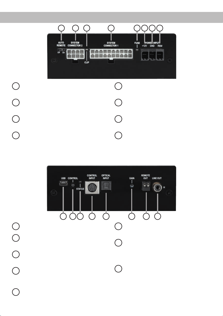
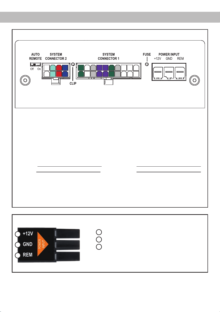
Anschluss- und Bedienelemente
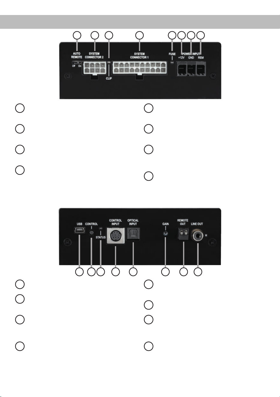
1
Auto Remote
Dient zum Aktivieren bzw. Deaktivieren der
automatischen Einschaltung des Verstärkers.
2
System Connector 2
Anschluss für Lautsprecher und / oder Sub-
woofer.
3
Clipping LED
Diese LED leuchtet rot, wenn einer der
Analogeingänge übersteuert wird.
4
System Connector 1
Anschluss für den UP 7DSP Kabel-
baum. Verwenden Sie ausschließlich das
beiliegende Original-Anschlusskabel, um
den Verstärker mit dem Autoradio zu verbin-
den.
5
Fuse LED
LED zur Anzeige einer defekten Sicherung
im Gerät.
6
+12 V
Anschluss für das Versorgungsspannungs-
kabel +12 V der Batterie.
7
GND
Anschluss des Massekabels (Minuspol der
Batterie oder Fahrzeugchassis).
8
REM
Anschluss für die Remoteleitung.
1
2 3 4 5 6 7 8
9
USB Eingang
Dient zum Anschluss an den Computer.
10
Control Taster
Dient zum Umschalten der Sound Setups
oder zum Resetten des Gerätes.
11
Status LED
Die Status LED zeigt den Betriebszustand
und den ausgewählten Speicherbereich an.
12
Control Input
Multifunktionsanschluss - dient zum An-
schluss einer Fernbedienung und weiterem
MATCH UP 7DSP Zubehör.
13
Optical Input
Optischer Eingang im SPDIF-Format für digi-
tale Stereosignale.
14
Gain
Regler zum Einstellen der Eingangsempnd-
lichkeit.
15
Remote Out
Der Remote-Ausgang dient zum Einschalten
weiterer Verstärker. Dieser Ausgang muss
bei Verwendung des Line Out-Ausgangs ge-
nutzt werden.
16
Line Out
Mono-Vorverstärkerausgang zum Anschluss
weiterer Verstärker. Zum Einschalten dieser
Verstärker muss der Remote-Ausgang ver-
wendet werden.
10 119 16
15
1312 14

4
1
Auto Remote
Die Einschaltung des UP 7DSP Verstärkers erfolgt
automatisch bei Ansteuerung über die Highlevel-
Eingänge des System Connector 1 oder sobald ein
Remote-Signal am Remote-Eingang (REM) anliegt.
Mit Hilfe des Auto Remote Schalters kann die auto-
matische Einschaltung über die Highlevel-Eingänge
des System Connector 1 aktiviert bzw. deaktiviert
werden.
Die Deaktivierung sollte vorgenommen werden,
wenn es beispielsweise zu Störgeräuschen beim
Ein- und Ausschalten des Verstärkers kommt.
Hinweis: Werkseitig ist die automatische Ein-
schaltung über die Highlevel-Eingänge aktiviert
(Auto Remote = On).
Hinweis: Wird die automatische Einschaltung des
Verstärkers deaktiviert, muss der Remote-Eingang
belegt werden. Eine automatische Einschaltung
über den Lautsprecher eingang des System Con-
nector 1 ist dann nicht mehr möglich.
2
System Connector 2
Diese Buchse dient zum Anschluss von Laut-
sprechern und / oder Subwoofern. Verwenden
Sie zum Anschluss der Lautsprecher / Subwoofer
ausschließlich das mitgelieferte Anschlusskabel
mit dem 8-poligen Stecker und den offenen Kabel-
enden. Die Impedanz der Lautsprecher darf 2 Ohm
nicht unterschreiten.
Achtung: Die Verwendung anderer oder ähnlicher
Kabelbäume kann zur Zerstörung des Verstärkers,
des Autoradios oder der angeschlossenen Laut-
sprecher führen. In jedem Fall führt dies zum Erlö-
schen der Garantie.
3
Clipping LED
Diese LED leuchtet rot, wenn einer der vier Hoch-
pegel-Lautsprechereingänge übersteuert wird. Die
LED hat keine Funktion bei Ansteuerung des Ver-
stärkers über den Digitaleingang (Optical Input)
oder ein MEC Modul.
4
System Connector 1
Diese Buchse dient als Signaleingang zum An-
schluss des Werksradios und als Signalausgang
der Verstärkerkanäle A - D zum Anschluss der
Lautsprecher. Die Impedanz der Lautsprecher darf
4 Ohm nicht unterschreiten. Verwenden Sie zur
Verbindung der MATCH UP 7DSP mit dem Original-
radio ausschließlich den mitgelieferten Kabelbaum
oder eine Alternative aus dem MATCH Zubehörpro-
gramm.
Achtung: Die Verwendung anderer oder ähnlicher
Kabelbäume kann zur Zerstörung des Verstärkers,
des Autoradios oder der angeschlossenen Laut-
sprecher führen. In jedem Fall führt dies zum Erlö-
schen der Garantie.
5
Fuse LED
Sollten die Sicherungen im Inneren des Gerätes
durch eine Fehlfunktion zerstört werden, wird die-
ses durch das Aueuchten der roten LED ange-
zeigt. Die Sicherungen im Verstärker dürfen nur mit
den gleichen Werten (2 x 25 A) ersetzt werden, um
eine Beschädigung des Gerätes zu verhindern. Hö-
here Werte können zu gefährlichen Folgeschäden
führen!
6
+12 V
Anschluss für das +12 V Versorgungskabel. Das
Kabel ist am Pluspol der Batterie anzuschließen
und sollte einen empfohlenen Querschnitt von min-
destens 6 mm² aufweisen.
7
GND
Das Kabel sollte am zentralen Massepunkt (dieser
bendet sich dort wo der Minuspol der Batterie zum
Metallchassis des Kfz geerdet ist) oder an einer
blanken, von Lackresten befreiten Stelle des Kfz-
Chassis angeschlossen werden. Der empfohlene
Querschnitt beträgt mindestens 6 mm².
8
REM
Der Remote-Eingang dient zum Einschalten der
UP 7DSP, sofern die am System Connector 1 an-
geschlossene Signalquelle die automatische Ein-
schaltung (Auto Remote) nicht aktiviert oder der
Verstärker bewusst nur über ein Remote-Signal des
REM ein- und ausgeschaltet werden soll.
Die Remoteleitung wird mit dem Remote-Ausgang /
Antennenanschluss des Steuergerätes (Radio) ver-
bunden. Dieser ist nur aktiviert, wenn das Steuerge-
rät eingeschaltet ist. Somit wird der Verstärker mit
dem Steuergerät ein- und ausgeschaltet.
Hinweis: Dieser Eingang muss nicht belegt wer-
den, wenn der System Connector 1 benutzt wird.
Inbetriebnahme und Funktionen

5
9
USB Eingang
Mit Hilfe dieses Eingangs wird die UP 7DSP über
das beiliegende Kabel mit dem Computer verbun-
den und kann anschließend über das DSP PC-Tool
konguriert werden.
Hinweis: Es können keine USB Speichermedien
angeschlossen werden.
10
Control Taster
Mit Hilfe des Control Tasters lässt sich zwischen
den Speicherbereichen eins und zwei umschalten.
Zum manuellen Umschalten der zwei Setups muss
der Control Taster eine Sekunde lang gedrückt wer-
den. Der Umschaltvorgang wird durch einmaliges
rotes Blinken der Status LED angezeigt. Wird der
Taster länger als fünf Sekunden gedrückt, so wird
das Gerät resettet und der gesamte interne Spei-
cher gelöscht! Anschließend wird dies durch ein
rotes Dauerblinken der Status LED angezeigt.
Achtung: Nach dem Resetten des Gerätes kann
die UP 7DSP keine Audiosignale mehr wiederge-
ben, bis ein neues Sound Setup eingespielt wurde.
11
Status LED
Die Status LED zeigt den Betriebszustand und das
aktuell ausgewählte Setup des Verstärkers an.
Grün: Setup 1 geladen.
Orange: Setup 2 geladen.
Rot: Schutzschaltung für Unterspan-
nung aktiv.
Rot blinkend: Interner Setup-Speicher leer (Ein
neues DSP Setup muss über die
DSP PC-Tool Software einge-
spielt werden).
12
Control Input
Dieser Multifunktionsanschluss dient zum An-
schluss von MATCH Zubehörprodukten, wie bei-
spielsweise einer Fernbedienung mit deren Hilfe
diverse Funktionen des DSP-Verstärkers gesteuert
werden können.
Die Funktionalität muss je nach Typ der Fernbedie-
nung zuerst im „Device Conguration Menu“ der
DSP PC-Tool Software oder an der Fernbedienung
selbst konguriert werden.
13
Optical Input
Optischer Eingang im SPDIF-Format für den An-
schluss an Signalquellen mit digitalem Ausgang.
Die „Sampling Rate“ dieses Eingangs muss zwi-
schen 12 - 96 kHz liegen. Das Eingangssignal wird
automatisch an die interne Abtastrate angepasst.
Um diesen Eingang zu aktivieren und in der Laut-
stärke regeln zu können, wird eine optional erhält-
liche Fernbedienung empfohlen.
Hinweis:
Es können ausschließlich Stereosignale
und keine MP3- oder Dolby-codierten Daten verar
-
beitet werden!
Hinweis:
Eine gleichzeitige Verwendung des op-
tischen Eingangs zusammen mit den Hochpegel-
Signaleingängen des System Connector 1 ist mög
-
lich.
14
Gain
Mit Hilfe dieses Drehreglers kann die Eingangs-
empndlichkeit der Highlevel-Eingänge um max.
6 dB angehoben werden, sofern die Signalquelle
nicht ausreichend Pegel liefert.
Dieser Regler ist kein Lautstärkeregler, sondern
dient nur der Anpassung. Die Einstellung dieses
Reglers beeinusst nicht den optischen Eingang.
Der Regelbereich reicht von 11 V (Linksanschlag)
bis 5 V (Rechtsanschlag).
Hinweis: Werkseitig ist eine Eingangsempndlich-
keit von 11 V (Linksanschlag) eingestellt.
Dies ist in nahezu allen Fällen bereits die optimale
Einstellung.
15
Remote Out
Der Remote-Ausgang dient dazu weitere Verstärker
einzuschalten. Verwenden Sie in jedem Fall diesen
Ausgang, wenn Sie weitere Verstärker an den Line
Out der UP 7DSP anschließen, da es ansonsten zu
Störgeräuschen kommen kann.
Dieser Ausgang aktiviert sich automatisch, sobald
der Bootvorgang des DSP abgeschlossen ist. Zu-
dem wird dieser Ausgang bei aktiviertem „Power
Save Mode“ und bei Betriebssoftware-Updates ab-
geschaltet.
16
Line Out
Der Line Out ist ein Mono-Vorverstärker-Signalaus-
gang zum Anschluss von zusätzlichen Verstärkern,
der durch den „Balanced Audio Transformer“ von
der Eingangsmasse getrennt ist. Dadurch können
keine Störgeräusche aufgrund von Masseverschlei-
fungen auftreten.
Dieser Ausgang liefert eine maximale Ausgangs-

6
Inbetriebnahme und Funktionen
spannung von 3 Volt RMS. Wenn Sie diesen Aus-
gang verwenden, ist es zwingend erforderlich, den
Remote-Ausgang (Remote Out) zum Einschalten
des / der angeschlossenen Verstärker/s zu ver-
wenden, da ansonsten Störgeräusche auftreten
können.
Der Remote-Ausgang schaltet sich automatisch
während des Power Save Modus sowie bei einem
Software-Update ab.
Das Audiosignal kann mit Hilfe der DSP PC-Tool
Software unabhängig von den anderen Verstärker-
kanälen konguriert werden.
Spezielle Features der UP 7DSP
Class HD Technologie
In der UP 7DSP werden die Vorteile der Class H-
Technologie mit dem Prinzip eines Class D Ver-
stärkers kombiniert. Das Resultat ist ein unü-
bertroffener Wirkungsgrad, der herkömmliche
Class D-Verstärker nochmals übertrifft. Die Vorteile
spielt das Class HD-Konzept bei kleiner und mittle-
rer Aussteuerung aus, da das Netzteil die interne
Versorgungsspannung der Leistungsstufen in Ab-
hängigkeit von der Amplitude des Eingangs signals
regelt. Damit wird die mittlere, vom Verstärker er-
zeugte Verlustleistung drastisch reduziert.
Intelligenter Highlevel-Eingang ADEP.3
Moderne, ab Werk verbaute Autoradios werden
bezüglich der Diagnose der angeschlossenen Laut-
sprecher immer intelligenter. Speziell die neueste
Generation ist mit zusätzlichen Überwachungsfunk-
tionen ausgestattet, sodass bei Anschluss eines
zusätzlichen Verstärkers Fehlermeldungen oder
gar Fehlfunktionen auftreten können. Der neue
ADEP.3-Schaltkreis (Advanced Diagnostics Error
Protection Generation 3) verhindert diese Probleme
ohne die Lautsprecherausgänge des Radios bei ho-
hen Pegeln unnötig zu belasten.
Start-Stopfähigkeit
Das Netzteil im UP 7DSP Verstärker stellt die in-
terne Spannungsversorgung auch bei kurzfristigen
Einbrüchen bis hinab zu 6 Volt sicher. Damit ist ge-
währleistet, dass der Verstärker auch beim Motor-
start voll funktionsfähig bleibt. Wenn die Bordspan-
nung für länger als 5 Sekunden unter 10,5 Volt fällt,
geht der Verstärker in den „Protect Mode“ (Status
LED leuchtet dauerhaft rot), um eine weitere Entla-
dung der Batterie zu verhindern.
Automatic Digital Signal Detection
Die Umschaltung zwischen den analogen und dem
Digitaleingang erfolgt signalgesteuert. Sobald ein
Audiosignal am Optical Input detektiert wird, schal-
tet der Verstärker auf diesen Eingang um. In der
DSP PC-Tool Software kann diese Funktion deakti-
viert oder alternativ eine manuelle Steuerung über
eine optional erhältliche Fernbedienung gewählt
werden.
Power Save Modus
Der Power Save Modus erlaubt es, die Leistungs-
aufnahme der UP 7DSP (und ggf. zusätzlich ange-
schlossener Verstärker) drastisch zu reduzieren,
wenn für länger als 60 Sek. kein Eingangssignal
anliegt. Sobald der „Power Save Mode“ aktiv ist,
werden die internen Verstärkerstufen der UP 7DSP
sowie der Remote-Ausgang abgeschaltet und da-
mit die Stromaufnahme deutlich reduziert. Der
Verstärker geht innerhalb von 2 Sek. wieder in den
normalen Betriebszustand über, sobald ein Musik-
signal an seinem Eingang anliegt. Über die DSP
PC-Tool Software kann die Abschaltverzögerung
variiert bzw. komplett deaktiviert werden.
7
Einbau und Installation
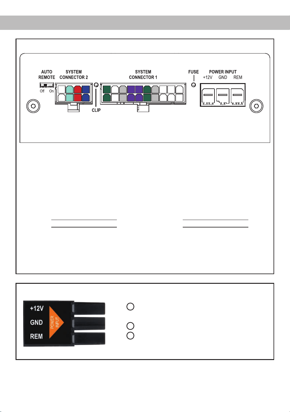
Abb. 1: Pinbelegung System Connector 1 und 2
System Connector 1
1. Highlevel-Lautsprechereingang hinten links (-) / C
2. Highlevel-Lautsprechereingang vorne links (-) / A
3. Highlevel-Lautsprechereingang vorne rechts (-) / B
4. Highlevel-Lautsprechereingang hinten rechts (-) / D
5. Lautsprecherausgang hinten rechts (-) / D
6. Lautsprecherausgang hinten links (-) / C
7. Lautsprecherausgang vorne rechts (-) / B
8. Lautsprecherausgang vorne links (-) / A
9. Masse* / Wichtig: Pin darf nicht belegt werden!
10. Masse*/ Wichtig: Pin darf nicht belegt werden!
11. Highlevel-Lautsprechereingang hinten links (+) / C
12. Highlevel-Lautsprechereingang vorne links (+) / A
13. Highlevel-Lautsprechereingang vorne rechts (+) / B
14. Highlevel-Lautsprechereingang hinten rechts (+) / D
15. Lautsprecherausgang hinten rechts (+) / D
16. Lautsprecherausgang hinten links (+) / C
17. Lautsprecherausgang vorne rechts (+) / B
18. Lautsprecherausgang vorne links (+) / A
19. +12 Volt* / Wichtig: Pin darf nicht belegt werden!
20. +12 Volt* / Wichtig: Pin darf nicht belegt werden!
System Connector 2
21. Nicht belegt
22. Subwooferausgang 1 (-) / E
23. Subwooferausgang 2 (-) / F
24. Lautsprecherausgang Center (-) / G
25. Nicht belegt
26. Subwooferausgang 1 (+) / E
27. Subwooferausgang 2 (+) / F
28. Lautsprecherausgang Center (+) / G
Abb. 2: Belegung Power Input Stecker
Steckeroberseite
A
+12 V - Zum Anschluss des +12 V Versorgungskabels.
B
GND - Zum Anschluss des Massekabels.
C
REM - Remote-Eingang zum Anschluss an den
Remote-Ausgangs der Signalquelle.
A
B
C
* Nicht belegt beim beiliegenden System Connector 1 Anschlusskabel.
10921 22 23 24
25 26 27 28
1 2 3 4
11 12 13 14
5 6 7 8
15 16 17 18 19 20

8
Der MATCH UP 7DSP Verstärker wird wie nach-
folgend beschrieben montiert und angeschlos-
sen.
Achtung: Für die Durchführung der nachfolgenden
Schritte werden Spezialwerkzeuge und Fachwis-
sen benötigt. Um Anschlussfehler und Beschädi-
gungen zu vermeiden, fragen Sie im Zweifelsfall
Ihren Fachhändler und beachten Sie zwingend die
allgemeinen Anschluss- und Einbauhinweise (siehe
Seite 2).
1. Anschluss des System Connector 1
1. Anschluss der Highlevel-Lautsprecherein-
gänge: Die Highlevel-Lautsprechereingänge
(siehe Abb. 1 Seite 7, Nr. 1 - 4 und Nr. 11 - 14)
können mit Hilfe des beiliegenden MATCH
Anschlusskabels direkt mit den Lautspre-
cherausgängen des Werks- bzw. Nachrü-
stradios verbunden werden. Dabei müssen
nicht zwingend alle Eingänge belegt werden.
Es ist ausreichend zwei der vier Highlevel-
Lautsprechereingänge zu belegen. Mit Hilfe
der DSP PC-Tool Software können die Ein-
gangssignale auf die acht Ausgangskanäle
des Verstärkers individuell aufgeteilt werden.
Achten Sie bitte auf eine korrekte Polung!
Wenn Sie einen oder mehrere Anschlüsse
verpolen, kann dadurch die Funktion des
Verstärkers beeinträchtigt werden. Bei Ver-
wendung dieses Eingangs muss der Remo-
te-Eingang (REM) nicht belegt werden, da
sich der Verstärker automatisch einschaltet,
sobald ein Lautsprechersignal anliegt.
2. Anschluss der Lautsprecherausgänge: Die
Lautsprecherausgänge (siehe Abb. 1 Sei-
te 7, Nr. 5 - 8 und Nr. 15 - 18) können mit
Hilfe des beiliegenden MATCH Anschluss-
kabels direkt mit den Lautsprecherleitungen
verbunden werden. Verbinden Sie niemals
die Lautsprecherleitungen mit der Kfz-Mas-
se (Fahrzeugkarosserie). Dieses kann Ihren
Verstärker zerstören. Achten Sie darauf,
dass alle Lautsprechersysteme phasenrich-
tig angeschlossen sind, d.h. Plus zu Plus
und Minus zu Minus. Vertauschen von Plus
und Minus hat einen Totalverlust der Bass-
wiedergabe zur Folge. Der Pluspol ist bei
den meisten Lautsprechern gekennzeichnet.
Die Impedanz pro Kanal darf 4 Ohm nicht
unterschreiten, da sonst die Schutzschal-
tung des Verstärkers aktiviert wird.
2. Anschluss des System Connector 2
An den System Connector 2 können mit Hilfe
des beiliegenden MATCH Anschlusskabels
zwei Subwoofer und ein Center-Lautsprecher
angeschlossen werden (siehe Abb. 1 Seite 7,
Nr. 22 - 28). Verbinden Sie niemals die Laut-
sprecherleitungen mit der Kfz-Masse (Fahr-
zeugkarosserie). Dieses kann Ihren Verstärker
zerstören. Achten Sie darauf, dass alle Laut-
sprechersysteme phasenrichtig angeschlossen
sind, d.h. Plus zu Plus und Minus zu Minus.
Vertauschen von Plus und Minus hat einen
Totalverlust der Basswiedergabe zur Folge.
Der Pluspol ist bei den meisten Lautsprechern
gekennzeichnet. Die Impedanz pro Kanal
darf 2 Ohm nicht unterschreiten, da sonst die
Schutzschaltung des Verstärkers aktiviert wird.
Achtung: Verwenden Sie zum Anschluss aus-
schließlich das mitgelieferte Anschlusskabel mit
dem 8-poligen Stecker und den offenen Kabel-
enden.
3. EinstellungderEingangsempndlichkeit
Mit Hilfe des Gain Drehreglers (Seite 5,
Punkt 14) kann die Eingangsempndlichkeit an
die Ausgangsspannung des angeschlossenen
Steuergerätes angepasst werden. Die Einstel-
lung dieses Reglers beeinusst nicht den op-
tischen Eingang!
Dieser Regler ist kein Lautstärkeregler, sondern
dient nur der Anpassung. Die Eingangsempnd-
lichkeit der Highlevel-Eingänge der UP 7DSP
ist ab Werk auf Linksanschlag justiert. Dies ist
in nahezu allen Fällen bereits die optimale Ein-
stellung. Sollte dennoch bei voll aufgedrehtem
Lautstärkeregler am Radio der Maximalpegel
zu gering sein, kann mit Hilfe des Gain Reglers
die Eingangsempndlichkeit um bis zu 6 dB an-
gehoben werden.
4. Anschluss einer digitalen Signalquelle
Sofern Sie über eine Signalquelle mit op-
tischem Digitalausgang verfügen, kann diese
an den Verstärker angeschlossen werden. Die
UP 7DSP ist werkseitig so konguriert, dass au-
Einbau und Installation

9
tomatisch auf den Digitaleingang umgeschaltet
wird, wenn dort ein Audiosignal anliegt. Diese
Funktion kann über die DSP PC-Tool Software
deaktiviert bzw. auf einen manuellen Modus (in
Verbindung mit einer optional erhältlichen Fern-
bedienung) geändert werden.
Die Einschaltautomatik des Verstärkers funktio-
niert bei Verwendung des Digitaleingangs nicht,
so dass der Remote-Eingang (REM) zwingend
belegt werden muss. Eine gleichzeitige Nut-
zung des Digitaleingangs sowie der Hochpegel-
Signaleingänge ist möglich.
Wichtig: Das digitale Audiosignal einer Quelle
ist üblicherweise nicht lautstärkegeregelt. Das
bedeutet, dass an sämtlichen Ausgängen der
UP 7DSP der volle Pegel anliegt. Dies kann im
Extremfall die angeschlossenen Lautsprecher
zerstören. Wir raten deshalb dringend dazu,
eine optionale Fernbedienung zur Einstellung
der Lautstärke der digitalen Signaleingänge zu
verwenden!
Hinweis: Die UP 7DSP kann nur unkompri-
mierte, digitale Stereo PCM-Signale mit einer
Abtastrate zwischen 12 kHz und 96 kHz ver-
arbeiten. Es können keine
MP3- oder
Dolby-
codierten Daten verarbeitet werden, sondern
ausschließlich Stereosignale.
5. Anschluss der Stromversorgung
Vor dem Anschluss des +12 V Versorgungs-
kabels an das Bordnetz muss die Autobatte-
rie abgeklemmt werden.
Das +12 V Stromkabel ist am Pluspol der Bat-
terie anzuschließen. Die Plusleitung sollte in
einem Abstand von max. 30 cm von der Batte-
rie mit einer Hauptsicherung (50 A) abgesichert
werden. Verwenden Sie bei kurzen Leitungen
(< 1 m) einen Querschnitt von mindestens
6 mm². Bei längeren Leitungen empfehlen wir
einen Querschnitt von 10 mm² bis 16 mm².
Das Massekabel (gleicher Querschnitt wie das
+12 V Kabel) muss an einem blanken, von
Lackresten befreiten Massepunkt des Kfz-
Chassis oder direkt an dem Minuspol der Auto-
batterie angeschlossen werden.
6. Anschluss des Remote-Eingangs
Der Remote-Eingang muss mit dem Remote-
Ausgang des Radios verbunden sein, sofern
ausschließlich der Digitaleingang des Verstär-
kers als Signaleingang genutzt wird. Es wird
dringend davon abgeraten, den Remote-Ein-
gang des Verstärkers über das Zündungsplus
des Fahrzeugs zu steuern, um Störgeräusche
beim Ein- und Ausschalten zu vermeiden.
Bei Verwendung der Highlevel-Eingänge des
System Connector 1 muss der Remote-Ein-
gang nicht belegt werden, sofern das ange-
schlossene Radio über BTL-Ausgangsstufen
verfügt.
7. KongurationdesRemote-Eingangs
Die Einschaltung der MATCH UP 7DSP erfolgt
automatisch bei Ansteuerung über die Hoch-
pegel-Lautsprechereingänge des System Con-
nectors 1 oder sobald ein Remote-Signal am
Remote-Eingang (REM) anliegt.
Mit Hilfe des Auto Remote Schalters (Seite 4,
Punkt 1) kann die automatische Einschaltung
deaktiviert werden. Dies sollte vorgenommen
werden, wenn es beispielsweise zu Störge-
räuschen beim Ein- und Ausschalten des Ver-
stärkers kommt.
Hinweis: Wird die automatische Einschaltung
des Verstärkers deaktiviert, muss der Remote-
Eingang belegt werden. Eine automatische
Einschaltung über den Hochpegel-Lautspre-
chereingang des System Connectors 1 ist dann
nicht mehr möglich. Um die automatische Ein-
schaltung zu deaktivieren, stellen Sie den Auto
Remote Schalter auf die Schalterstellung „Off“.
8. KongurationdesinternenDSPs
Es wird dringend empfohlen vor der ersten
Inbetriebnahme die grundlegenden Einstel-
lungen im Verstärker mit Hilfe der DSP PC-
Tool Software vorzunehmen.
Eine Missachtung kann zur Zerstörung der
angeschlossenen Lautsprecher / Verstärker
führen. Speziell bei Verwendung der UP 7DSP
in vollaktiven Systemen besteht sonst Zerstö-
rungsgefahr für die Hochtöner. Informationen
zum Anschluss des Verstärkers an einen PC
nden Sie auf Seite 12.
9. Anschluss des Remote-Ausgangs
Dieser Ausgang (Remote Out) dient dazu, ei-
nen am Line Out angeschlossenen Zusatzver-

10
stärker mit einem Remote-Signal zu versorgen.
Bitte verwenden Sie ausschließlich dieses
Signal zur Einschaltung externer Verstärker, um
Ein- und Ausschaltgeräusche zu vermeiden.
Einbau und Installation
Anschluss mit Hilfe des PP-ISO Kabels
Um die Installation der UP 7DSP an ein Werks- oder
Nachrüstradio deutlich zu vereinfachen, kann der
Verstärker auch mit Hilfe eines optional erhältlichen
PP-ISO Kabels (2,2 m Version - Art. Nr. H424922)
angeschlossen werden. Über dieses Kabel wird der
Verstärker mit dem Highlevel-Signal vom Radio ver-
sorgt und speist über seine Lautsprecherausgänge
direkt die Lautsprecher. Zudem muss bei dieser
Installation kein Kabel des Werkssoundsystems
durchtrennt werden.
ACHTUNG: Die Versorgungsspannungslei-
tungen des PP-ISO Kabels dürfen unter keinen
Umständen zur Spannungsversorgung des Ver-
stärkers verwendet werden. Beim direkten An-
schluss der UP 7DSP an die Spannungsversor-
gung des Radios riskieren Sie massive Schäden
an der Bordnetzelektrik Ihres Fahrzeuges bis
hin zu einem Kabelbrand!
Im Folgenden wird der Anschluss an das Werksra-
dio beschrieben:
1. Nachdem das Radio mit Hilfe der entspre-
chenden Werkzeuge ausgebaut ist, trennen Sie
den Fahrzeugkabelbaum vom Autoradio. Ver-
binden Sie den Fahrzeugkabelbaum anschlie-
ßend mit der Kupplung des PP-ISO Kabels, si-
ehe Abb. 3
1
. Je nach Fahrzeugtyp benötigen
Sie hierfür gegebenenfalls einen fahrzeugspezi-
schen ISO-Adapter Abb. 3
4
. Eine Liste aller
Fahrzeuge und der eventuell benötigten Adap-
ter nden Sie auf www.audiotec-scher.com.
2. Verbinden Sie die ISO-Stecker des PP-ISO Ka-
bels siehe Abb. 3
2
mit dem Autoradio.
3. Anschließend verbinden Sie den 20-poligen
Stecker des PP-ISO Kabels mit dem Verstärker
Abb. 3
3
.
4. Wichtig: Trennen Sie nun die Kabelverbin-
dungen der Spannungsversorgungsleitungen
des PP-ISO Kabelbaums (gelb und schwarz),
siehe Abb. 3
5
. Nachdem die Kabelverbin-
dungen getrennt wurden müssen die offenen
Enden einzeln isoliert werden.
5. Schließen Sie den UP 7DSP Verstärker, wie im
Punkt 5 auf Seite 9 beschrieben, an das Bord-
netz des Fahrzeugs an.
Vor dem Anschluss des +12 V Versorgungs-
kabels an das Bordnetz muss die Autobatte-
rie abgeklemmt werden.
Hinweis: MOST-Bus
Bei einigen Fahrzeugen kann es notwendig sein, die
Lichtleiterverbindung aus dem Original-Radioan-
schlussstecker auszulösen und stattdessen in den
Radio-Stecker eines ISO-Adapters einzustecken.
Hierfür ist extra eine Aussparung im ISO-Adapter
vorhanden. Dies ist zwingend bei allen Fahrzeugen
notwendig, die einen Lichtleiteranschluss im Origi-
nalradiokabelbaum haben.
11
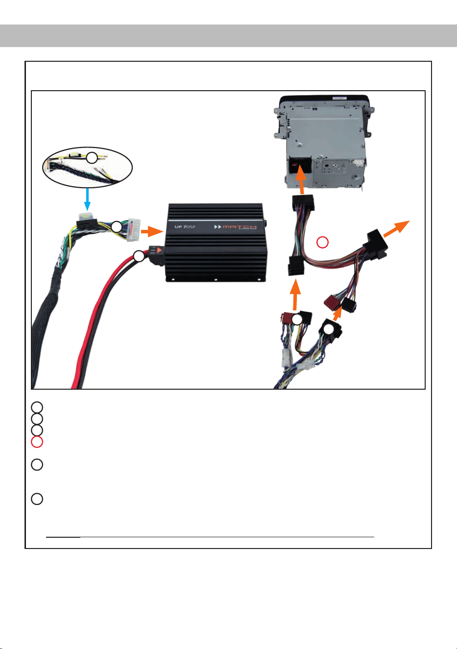
Abb. 3: Anschluss des Verstärkers an das Autoradio mit Hilfe des PP-ISO Kabels
1
ISO-Kupplung - hier wird der Kabelbaum des Originalradios oder ein ISO-Adapter eingesteckt.
2
ISO-Stecker - diese werden in das Originalradio oder in den ISO-Adapter eingesteckt.
3
Dieser 20-polige Stecker wird in den MATCH UP 7DSP Verstärker eingesteckt.
4
Optional: ISO-Adapter - sollten die ISO-Stecker des PP-ISO Kabelbaums nicht zum Originalradio
passen, muss ein ISO-Adapter verwendet werden.
5
Wichtig: Trennen Sie die Kabelverbindungen der Spannungsversorgungsleitungen des PP-ISO
Kabelbaums (gelb und schwarz). Nachdem die Kabelverbindungen getrennt wurden, müssen die
offenen Enden einzeln isoliert werden.
6
Der Stromanschluss der UP 7DSP wird mit Hilfe eines geeigneten Kabels (Querschnitt min.
10 mm²) direkt an die Batterie angeschlossen - die Plusleitung muss kurz vor der Batterie noch
einmal abgesichert werden.
Wichtig: Die Stromversorgung der UP 7DSP erfolgt niemals über das PP-ISO Kabel!
Kupplung und Stecker
für Originalkabelbaum
oder ISO-Adapter
Kupplung für
Originalkabel-
baum
1
2
3
4
6
5

12
Die MATCH UP 7DSP kann mit Hilfe der
DSP PC-Tool Software frei konguriert werden. Die
Software stellt alle Funktionen übersichtlich und
bedienerfreundlich zur Verfügung, so dass Sie die-
se individuell einstellen können. Dabei können alle
acht DSP Kanäle separat eingestellt werden.
Bevor Sie den Verstärker das erste Mal an einen
Computer anschließen, gehen Sie auf unsere
Homepage und laden die aktuellste Software Ver-
sion des DSP PC-Tools herunter. Es ist ratsam re-
gelmäßig nach Updates der Software zu schauen,
damit das Gerät immer auf dem aktuellsten Stand
ist.
Die Software sowie die dazugehörige Bedienungsan-
leitung nden Sie auf www.audiotec-scher.com.
Es wird dringend empfohlen die Bedienungsanlei-
tung der Software (Sound Tuning Magazin) vor der
ersten Benutzung durchzulesen, um Komplikati-
onen und Fehler zu vermeiden.
Wichtig: Stellen Sie sicher, dass der MATCH
UP 7DSP Verstärker bei der ersten Installation der
Software noch nicht am PC angeschlossen ist. Ver-
binden Sie diesen erst, wenn die Software samt der
USB-Treiber vollständig installiert ist.
Im folgenden Abschnitt lesen Sie die wichtigsten
Schritte zum Anschluss und der ersten Inbetrieb-
nahme:
1. Laden Sie die DSP PC-Tool Software unter
www.audiotec-scher.com herunter und in-
stallieren diese auf ihrem Computer.
2. Schließen Sie danach den Verstärker mit dem
beiliegenden USB-Kabel an den Computer
an. Wenn Sie längere Distanzen zu überbrü-
cken haben, verwenden Sie bitte eine aktive
USB-Verlängerung mit integriertem Repeater
und kein passives USB-Kabel.
3. Schalten Sie erst den Verstärker ein und star-
ten Sie anschließend die Software. Sofern die
Betriebssoftware des Verstärkers nicht mehr
aktuell ist, wird diese automatisch aktualisiert.
4. Nun können Sie die UP 7DSP mithilfe der DSP
PC-Tool Software frei kongurieren. Nützliche
Hinweise zur korrekten Einstellung entnehmen
Sie z.B. unserem „Sound Tuning Magazin“,
welches auf unserer Webseite zum Download
bereit steht.
Achtung: Es wird dringend empfohlen, vor der er-
sten Inbetriebnahme die Lautstärke am Radio auf
Minimum zu drehen und am Line Out des Verstär-
kers noch nichts anzuschließen, bis die grundle-
genden Einstellungen im Verstärker vorgenommen
wurden. Speziell bei Verwendung der UP 7DSP in
vollaktiven Systemen besteht sonst Zerstörungsge-
fahr für die Lautsprecher.
Anschluss an den Computer
13
Der MATCH UP 7DSP bietet einzigartige DSP-
Sound effekte wie das „Augmented Bass Proces-
sing“, den „StageXpander“, den „RealCenter“ und
noch mehr.
Um jedoch in den Genuss aller DSP-Soundeffekte
zu kommen, müssen bei der Hard- und Software-
konguration bestimmte Einstellungen vorgenom-
men werden.
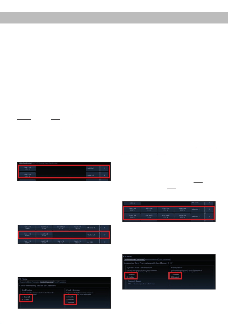
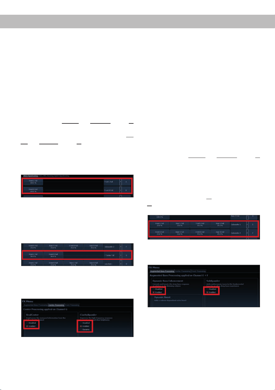
Hinweise für das Center Processing mit seiner
RealCenter- und ClarityXpander-Funktion
Um die RealCenter- und ClarityXpander-Funktion für
einen Center-Lautsprecher nutzen zu können, müs-
sen folgende Schritte durchgeführt werden:
1. Sie benötigen mindestens ein linkes und ein
rechtes analoges oder digitales Eingangssignal.
2. Öffnen Sie das IO-Menü im DSP PC-Tool. Rou-
ten Sie das linke und das rechte analoge oder
digitale Eingangssignal (kein Summensignal) auf
die Ausgangskanäle A und B (siehe Beispiel im
nachfolgenden Bild). Es spielt dabei keine Rolle
ob der Ausgangskanal als Front-, Rear-, Center-
Kanal etc. deniert ist.
Hinweis: Die beste Performance erzielen Sie,
wenn das Eingangssignal ein Fullrange-Signal
ist.
3. Bilden Sie aus den gleichen zwei Eingangs-
signalen ein Summensignal und routen dies auf
den Ausgangskanal G. Dieser sollte als „Center
Full“ deniert werden.
4. Wiederholen Sie die Schritte zwei und drei für
alle genutzten Routing-Matrizen.
5. Wechseln Sie nun in das FX-Menü und aktivieren
den gewünschten Soundeffekt durch das Setzen
eines Hakens.
Hinweis: Das Center Processing wird ausschließ-
lich auf den Ausgangskanal G angewendet.
Hinweise für die StageXpander- und
ClarityXpander-Funktion
Die Einstellungen des StageXpanders und Front
ClarityXpanders wirken typischerweise auf die Ka-
näle A und B. Sollten Sie jedoch ein 2-Wege-Front-
system vollaktiv über die Kanäle A bis D ansteuern,
dann muss dieses Sound-Feature auf alle vier Ka-
näle A bis D Einuss nehmen. Dazu müssen Sie im
FX-Menü unter „Front Processing“ bei der „Link to
C+D“-Funktion einen Haken setzen.
Hinweise für das Augmented Bass Processing
mit seiner Dynamic Bass Enhancement- und
SubXpander-Funktion
Auch für das Augmented Bass Processing müssen
bestimmte Einstellungen vorgenommen werden,
um dessen Soundeffekte anwenden zu können.
1. Sie benötigen mindestens ein linkes und ein
rechtes analoges oder digitales Eingangssignal.
Hinweis: Wenn Sie den analogen Signaleingang
verwenden, erzielen Sie die beste Performance
bei Belegung aller vier Eingänge.
2. Öffnen Sie das IO-Menü im DSP PC-Tool. Bil-
den Sie nun ein Summensignal aus allen linken
und rechten analogen oder digitalen Eingangs-
signalen und routen dies einmal auf den Aus-
gangskanal E und einmal auf Ausgangskanal F.
3. Wiederholen Sie das Routing für alle genutzten
Routing-Matrizen.
4. Wechseln Sie nun in das FX-Menü und aktivieren
den gewünschten Soundeffekt durch das Setzen
eines Hakens.
Hinweis: Das Augmented Bass Processing wird
ausschließlich auf die Ausgangskanäle E und F an-
gewendet.
KongurationshinweisefürdieDSP-Soundeffekte
14
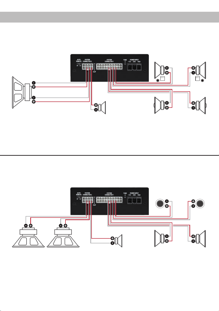
Kongurationsbeispiele
7-Kanal Anwendung mit Center und 2 x 2 Ohm Subwoofer
2-Wege Passivsystem + Koaxialsystem + Center + Subwoofer mit Doppelschwingspule (Dual Voice Coil)
2 x 2 Ohm Subwoofer
7-Kanal Anwendung mit 2-Wege Aktivsystem, Center und zwei 1 x 2 Ohm Subwoofern
Hochtöner + Tiefmitteltöner + Center + zwei Subwoofer mit einer Schwingspule (Single Voice Coil)
Center
SW = Schwingspule
Center
Links Rechts
Hochtöner
Links Rechts
SW 2
SW 1
1 x 2 Ohm Subwoofer
Links Rechts
Vorne
Links Rechts
Hinten
Tiefmitteltöner
15
Einbau einer MATCH Extension Card
Der MATCH UP 7DSP Verstärker kann durch die
Montage einer MATCH Extension Card (MEC) um
weitere Schnittstellen wie beispielsweise einem
Bluetooth
®
Audio Streaming Modul, einer High Re-
solution Audio USB Soundkarte etc. erweitert wer-
den.
Zur Montage einer MEC muss das Seitenblech der
UP 7DSP demontiert und gegen das der MEC bei-
liegende Seitenblech ausgetauscht werden.
Achtung: Installieren Sie ausschließlich für den
UP 7DSP Verstärker vorgesehene MEC Module
an der dafür vorgesehenen Position. Die Be-
nutzungeinesnichtfürdasGerätspezizierten
MEC Moduls oder eine Installation an einer nicht
dafür vorgesehenen Position im Gerät kann zu
Schäden am MEC Modul, dem Verstärker, des
Radios oder anderen angeschlossenen Geräten
führen.
Im folgenden Abschnitt nun die wichtigsten Schritte
zum Einbau und der ersten Inbetriebnahme eines
MEC Moduls:
1. Ziehen Sie zunächst alle Steckverbindungen
vom Gerät ab.
2. Lösen Sie die zwei Schrauben des Seiten-
blechs der Geräteseite mit dem USB Eingang
mit einem Kreuzschlitzschraubendreher und
entfernen dieses.
3. Ziehen Sie nun das Bodenblech zur Seite he-
raus.
4. Bereiten Sie das Modul für den Einbau in das
Gerät vor. Informationen dazu entnehmen Sie
bitte der Bedienungsanleitung des jeweiligen
MEC Moduls.
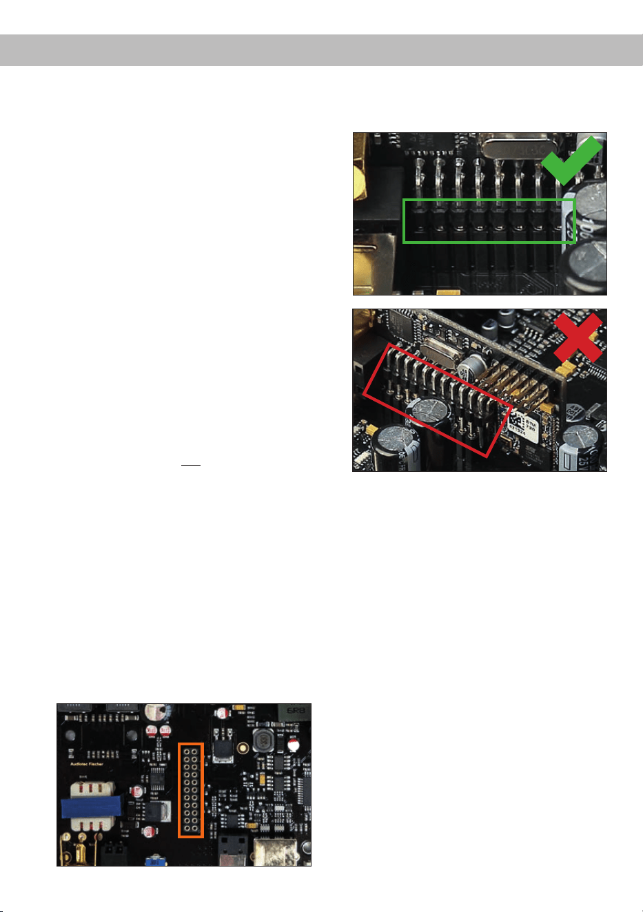
5. Stecken Sie das MEC Modul in den im Gerät
vorgesehenen Sockel (siehe Markierung im
nachfolgenden Bild).
6. Achten Sie auf den richtigen Sitz des MEC Mo-
duls und darauf, dass alle Kontaktstifte vollstän-
dig im Sockel stecken.
7. Schieben Sie das Bodenblech wieder seitlich
in das Gehäuse des Verstärkers. Anschließend
befestigen Sie das neue, dem MEC Modul
beiliegende Seitenblech mit den Kreuzschlitz-
schrauben.
8. Verschrauben Sie das MEC Modul mit dem
Seitenblech. Genaue Informationen zur Befes-
tigung entnehmen Sie bitte der Bedienungsan-
leitung des jeweiligen Moduls.
9. Schließen Sie alle Steckverbindungen wieder
an das Gerät an.
10. Schalten Sie den Verstärker ein. Das installierte
MEC Modul wird nun automatisch vom Gerät
erkannt und die Status LED des MEC Moduls
leuchtet grün.
11. Das Modul kann nun in der DSP PC-Tool Soft-
ware konguriert werden.

16
Technische Daten
Leistung RMS / Max.
- @ 4 Ohm .......................................................................5 x 65 / 130 Watt (Front / Rear / Center Kanäle)
- Subwooferausgang an 2 Ohm……………………………2 x 160 / 320 Watt
Verstärkertechnologie ......................................................Class HD
Eingänge .........................................................................4 x Hochpegel-Lautsprechereingang
1 x Optisch SPDIF (12 - 96 kHz)
1 x MEC
1 x Remote In
Eingangsempndlichkeit .................................................. Hochpegel 5 - 11 Volt
Eingangsimpedanz Highlevel ..........................................13 Ohm
Ausgänge ........................................................................7 x Lautsprecherausgang
1 x Cinch
2 x Remote Out
Ausgangsspannung Cinch...............................................3 Volt RMS
Frequenzbereich..............................................................20 Hz - 22.000 Hz
DSP Auösung ................................................................64 Bit
DSP Rechenleistung .......................................................295 MHz (1,2 Mrd. MAC Operationen/Sekunde)
Abtastrate ........................................................................48 kHz
DSP Typ ..........................................................................Audio Signalprozessor
Signalwandler ..................................................................A/D: BurrBrown
D/A: BurrBrown
Signal- / Rauschabstand Digitaleingang..........................105 dB (A-bewertet)
Signal- / Rauschabstand Analogeingang.........................103 dB (A-bewertet)
Klirrfaktor (THD) ..............................................................< 0,03 %
Dämpfungsfaktor .............................................................> 100
Betriebsspannung............................................................10,5 - 16 Volt (max. 5 Sek. bis hinab zu 6 Volt)
Stromaufnahme ...............................................................450 mA
Max. Remote-Ausgangsstrom .........................................500 mA
Sicherung ........................................................................2 x 25 A LP-Mini-Stecksicherung
Zusätzliche Features ....................................................... Class HD-Technologie mit dynamisch geregeltem
Netzteil, ADEP.3-Schaltkreis, Start-Stop-Fähig-
keit, Control Input, USB, MEC Slot, Auto Remote-
Schalter, galvanisch getrennter Line Out
Abmessungen (H x B x T) ...............................................46 x 130 x 153 mm
Die Garantieleistung entspricht der gesetzlichen
Regelung. Von der Garantieleistung ausgeschlos-
sen sind Defekte und Schäden, die durch Überla-
stung oder unsachgemäße Behandlung entstanden
sind. Eine Rücksendung kann nur nach vorheriger
Absprache in der Originalverpackung, einer de-
taillierten Fehlerbeschreibung und einem gültigen
Kaufbeleg erfolgen.
Technische Änderungen und Irrtümer vorbehalten!
Für Schäden am Fahrzeug oder Gerätedefekte, her-
vorgerufen durch Bedienungsfehler des Gerätes,
können wir keine Haftung übernehmen. Dieses
Produkt ist mit einer CE-Kennzeichnung versehen.
Damit ist das Gerät für den Betrieb in Fahrzeugen
innerhalb der Europäischen Union (EU) zertiziert.
Garantiehinweis
Hinweis:
„Die Bluetooth
®
Wortmarke und die Logos sind eingetragene Warenzeichen der Bluetooth SIG, Inc. und jegliche Nutzung dieser Marken
durch die Audiotec Fischer GmbH geschieht unter Lizenz. Andere Handelsmarken und Handelsnamen gehören den jeweiligen Inhabern.“

17
Dear Customer,
Congratulations on your purchase of this innovative
and high-qual ity MATCH product.
Thanks to more than 30 years of experience in
research and development of audio products this
amplier sets new standards in the range of digital
ampliers.
We wish you many hours of enjoyment with your
new MATCH UP 7DSP.
Yours,
AUDIOTEC FISCHER
General installation instructions for MATCH
components
To prevent damage to the unit and possible injury,
read this manual carefully and follow all installation
instructions. This product has been checked for
proper function prior to shipping and is guaranteed
against manufacturing defects.
Before starting your installation, disconnect the
battery’s negative terminal to prevent damage
totheunit,reand/orriskofinjury.For a proper
performance and to ensure full warranty coverage,
we strongly recommend to get this product installed
by an authorized MATCH dealer.
Install your UP 7DSP in a dry location with sufcient
air circulation for proper cooling of the equipment.
For safety reasons, the UP 7DSP must be profes-
sionally installed. Therefore, use the two mounting
plates which are included in delivery. These are at-
tached to the bottom of the amplier with two short
screws which are included in delivery, too.
When screwing the amplier to the vehicle chassis,
carefully examine the area around and behind the
proposed installation location to ensure that there
are no electrical cables or components, hydraulic
brake lines or any part of the fuel tank located be-
hind the mounting surface. Failure to do so may re-
sult in unpredictable damage to these components
and possible costly repairs to the vehicle.
General instruction for connecting the UP 7DSP
amplier
The UP 7DSP amplier may only be installed in mo-
tor vehicles which have a 12 Volts negative terminal
connected to the chassis ground. Any other system
could cause damage to the amplier and the electri-
cal system of the vehicle.
The positive cable from the battery for the entire
sound system should be provided with a main fuse
at a distance of max. 30 cm from the battery. The
value of the fuse is calculated from the maximum
total current draw of the car audio system.
Use only the included MATCH cable or
the optional PP-ISO cable for connec-
tion of the UP 7DSP. The use of other
cables can result in damage of the ampli-
er, the headunit / car radioor the connected
loudspeakers! The fuses of the amplier may
only be replaced by identically rated fuses
(2x25A)toavoiddamageoftheamplier.
Prior to installation, plan the wire routing to avoid
any possible damage to the wire harness. All
cabling should be protected against possible
crushing or pinching hazards. Also avoid routing
cables close to potential noise sources such as
electric motors, high power accessories and other
vehicle harnesses.
Congratulations!
General instructions
18
Connectors and control units
1
Auto Remote
This switch allows to activate / deactivate the
automatic turn-on feature of the amplier
.
2
System Connector 2
Connector for loudspeakers and / or sub-
woofers.
3
Clipping LED
This LED lights up red if one of the analog
inputs is overdriven.
4
System Connector 1
Connector for the UP 7DSP cable harness.
Only use the supplied connection cable to
connect the amplier to the car radio.
5
Fuse LED
This LED will light up if the fuses inside the
amplier are blown.
6
+12 V
Connector for the +12 V power cable to the
positive terminal of the battery.
7
GND
Connector for the ground cable (negative
terminal of the battery or metal body of the
vehicle).
8
REM
Connector for the remote cable.
1 2 3 4 5 6 7 8
9
USB Input
Connects the UP 7DSP to your PC.
10
Control pushbutton
Use this button to either switch between the
setups or initiate a reset of the device.
11
Status LED
This LED indicates the operating mode of
the amplier and the setup that has been
chosen.
12
Control Input
Multifunction interface for e.g. an optional
remote control or other MATCH UP 7DSP
accessory.
13
Optical Input
Optical input for digital stereo signals (SPDIF
format).
14
Gain
Control for adjusting the input sensitivity.
15
Remote Out
The remote output has to be used to turn on /
off external ampliers that are connected to
the Line Out.
16
Line Out
Mono line output for connecting external am-
pliers. Make sure that the remote output is
used to turn on these devices.
10 119
16
15
1312 14

19
Initial start-up and functions
1
Auto Remote
The UP 7DSP will be turned on automatically if the
highlevel inputs of the System Connector 1 are
used or if a signal is applied to the remote input
(REM) terminal.
The Auto Remote switch allows to activate / de-
activate the automatic turn-on feature of the high-
level inputs of the System Connector 1. The feature
should be deactivated (Auto Remote = off) if there
are e.g. disturbing noises while switching on / off
the amplier.
Note: The automatic turn-on feature is activated ex
works (Auto Remote = on). If the automatic turn-on
function is deactivated it is mandatory to use the
remote input (REM) to power up the amplier! The
highlevel signal will be ignored in this case.
2
System Connector 2
This connector is used for connecting loudspeakers
and / or subwoofers. Solely use the connection ca-
ble with the 8-pole connector and ying leads which
is included in delivery to connect the loudspeakers /
subwoofers. The impedance per channel must not
be lower than 2 Ohms.
Caution: The use of other harnesses than the one
that is supplied with the amplier may cause severe
harm to the amplier, your head unit / car radio and
your loudspeakers. In any case the warranty will be
void!
3
Clipping LED
This LED lights up red if one of the four highlevel
inputs is overdriven. The LED has no function when
an input signal is applied to the digital input (Optical
Input) or to the MEC module.
4
System Connector 1
This connector is used as signal input from the OE
radio and as signal output of the amplier channels
A to D for connecting the loudspeakers. The imped-
ance per channel must not be lower than 4 Ohms.
Solely use this terminal only in combination with the
connection cable that is included in delivery of the
amplier or an appropriate cable harness from the
MATCH accessories program.
Caution: The use of other harnesses may cause
severe harm to the amplier, your head unit / car
radio and your loudspeakers. In any case the war-
ranty will be void!
5
Fuse LED
If a severe malfunction inside the amplier will blow
the internal fuses the LED lights up red. The fus-
es may only be replaced by identically rated fuses
(2 x 25 A) to avoid damage of the amplier.
6
+12 V
Connect the +12 V power cable to the positive ter-
minal of the battery. Recommended cross section:
min. 6 mm² / AWG 10.
7
GND
The ground cable should be connected to a common
ground reference point (this is located where the
negative terminal of the battery is grounded to the
metal body of the vehicle) or to a prepared metal lo-
cation on the vehicle chassis i.e. an area which has
been cleaned of all paint residues. Recommended
cross section: min. 6 mm² / AWG 10.
8
REM
This input has to be used to turn on / off the ampli-
er if the signal source which is connected to the
System Connector 1 is not activating the “automatic
turn-on” function (Auto Remote) or if the amplier
shall only be activated / deactivated by a remote
signal applied to the remote input.
The remote lead should be connected to the remote
output / automatic antenna (aerial positive) output
of the head unit / car radio. This is only activated
if the head unit / car radio is switched on. Thus the
amplier is switched on and off together with the
head unit / car radio.
Note: This input needn´t to be assigned if the high-
level inputs of the System Connector 1 are used.
9
USB Input
Connect your personal computer to the UP 7DSP
using the provided USB cable. The required
PC software to congure this amplier can be
downloaded from the Audiotec Fischer website
www.audiotec-scher.com.
Please note: It is not possible to connect any USB
storage devices.
10
Control pushbutton
The Control pushbutton allows the user to switch
between the two setup memory positions. To switch
between the setups the button has to be pressed

20
and held for one second. Switching is indicated by a
single red ash of the Status LED. Pressing the but-
ton for ve seconds completely erases the internal
memory. This is indicated by a constant red ashing
of the Status LED.
Attention: After erasing the setups from memory
the MATCH UP 7DSP will not reproduce any audio
output.
11
Status LED
The LED indicates the operating mode of the ampli-
er and which setup has been chosen.
Green: Setup 1 is loaded.
Orange: Setup 2 is loaded.
Red: Undervoltage protection circuit is
active.
Red ashing: Internal setup storage is empty (A
new setup has to be loaded via
the DSP PC-Tool software).
12
Control Input
This multi-functional connector is designed for
MATCH accessory products like a remote control
which allows to adjust several features of the am-
plier. Depending on the type of remote control, the
functionality at rst has to be dened in the “Device
Conguration Menu” of the DSP PC-Tool software
or on the remote control itself.
13
Optical Input
Optical input in SPDIF format for connecting signal
sources with a digital audio output. The sampling
rate of this input must be between 12 and 96 kHz.
The input signal is automatically adapted to the in-
ternal sample rate. In order to activate and control
the volume of this input, we recommend to use an
optional remote control.
Note: This amplier can only handle stereo input
signals and no MP3- or Dolby-coded digital audio
stream!
Note: It is possible to use the Optical Input and the
highlevel inputs of the System Connector 1 at the
same time.
14
Gain
This control allows to increase the input sensitivity
of the highlevel inputs up to max. 6 dB. The function
should only be used if the signal source has a low
output volume. This is not a volume control, it´s only
for adjusting the ampliers gain. Adjustments with
this control do not affect the optical input! The con-
trol range of the highlevel input goes from 11 Volts
(max. CCW position) to 5 Volts (max. CW position).
Please note: The input sensitivity ex works is set to
11 Volts (may. CCW position). This is denitely the
best setting for most applications.
15
Remote Out
We strongly recommend to use this output for turn-
ing on / off additional ampliers that are connected
to the Line Out of the MATCH UP 7DSP. This is es-
sential to avoid any interfering signals. This output
is activated automatically as soon as the boot pro-
cess of the DSP is completed. Additionally this out-
put will be turned off during the “Power Save Mode”
or a software update process.
16
Line Out
The Line Out is a mono oating-ground low level
output (max. 3 Vrms) for connecting additional pow-
er ampliers. A specially designed “Balanced Audio
Transformer” avoids any ground-loops that may
cause undesired alternator noise. Please make
sure that you always turn on / off external ampli-
ers using the remote output (Remote Out) of the
UP 7DSP. Additionally this output will be turned off
when the “Power Save Mode” of the amplier is ac-
tive as well as during software updates.
The output can be congured independently of the
other amplier channels with the DSP PC-Tool soft-
ware.
Initial start-up and functions

21
Unique Features of the UP 7DSP
Class HD technology
The UP 7DSP combines the advantages of a
Class H technology with the principle of a class D
amplier. The result is an unsurpassed efciency
which easily outperforms any conventional Class D
amplier.
By varying the internal supply voltage depending on
the amplier’s amplitude of the input signals, idle
losses are signicantly reduced and overall efcien-
cy is close to maximum at any time.
Smart highlevel input ADEP.3
Modern, factory-installed car radios incorporate so-
phisticated possibilities of diagnosing the connect-
ed speakers. In particular the latest generation of
car radios are equipped with additional monitoring
functions so that failure messages and loss of spe-
cic features (e.g. fader function) quite often appear
if a common amplier will be hooked up - but not
with the UP 7DSP.
The new ADEP.3 circuit (Advanced Diagnostics
Error Protection, 3rd Generation) avoids all these
problems without loading the speaker outputs of the
OE radio during high volumes unnecessarily.
Start-Stop capability
The switched power supply of the MATCH UP 7DSP
assures a constant internal supply voltage even if
the battery’s voltage drops to 6 Volts during engine
crank. If the supply voltage drops below 10.5 Volts
for more than ve seconds the amplier goes to
“Protect mode” (Status LED lights up red) in order
to avoid any further discharge of the car’s battery.
Automatic Digital Signal Detection
Switching from analog input to the digital input is
done automatically as soon as a signal is detec-
ted on the Optical Input. This feature can be deac-
tivated in the DSP PC-Tool software. Alternatively
you can use an optional remote control for manual
switching between analog and digital inputs.
Power Save Mode
The Power Save Mode is incorporated in the ba-
sic setup. It allows to signicantly reduce the power
consumption of the UP 7DSP and potentially con-
nected ampliers once there’s no input signal pres-
ent for more than 60 seconds. Please note that in
many up-to-date cars with “CAN” or any other in-
ternal bus structures it may happen that the radio
remains “invisibly” turned on for up to 45 min. even
after locking and leaving the car! Once the “Power
Save Mode“ is active the remote output and there-
fore the connected ampliers will be turned off. The
MATCH UP 7DSP will reactivate the remote output
within a second if a music signal is applied. It is pos-
sible to either modify the turn-off time of 60 sec. or
completely deactivate the “Power Save Mode” via
the DSP PC-Tool software.
22
Installation
Fig. 1: Pin conguration of the System Connector 1 and 2
System Connector 1
1. Highlevel loudspeaker input rear left (-) / C
2. Highlevel loudspeaker input front left (-) / A
3. Highlevel loudspeaker input front right (-) / B
4. Highlevel loudspeaker input rear right (-) / D
5. Loudspeaker output rear right (-) / D
6. Loudspeaker output rear left (-) / C
7. Loudspeaker output front right (-) / B
8. Loudspeaker output front left (-) / A
9. Ground* / Warning: Do not use this pin!
10. Ground* / Warning: Do not use this pin!
11. Highlevel loudspeaker input rear left (+) / C
12. Highlevel loudspeaker input front left (+) / A
13. Highlevel loudspeaker input front right (+) / B
14. Highlevel loudspeaker input rear right (+) / D
15. Loudspeaker output rear right (+) / D
16. Loudspeaker output rear left (+) / C
17. Loudspeaker output front right (+) / B
18. Loudspeaker output front left (+) / A
19. +12 Volts* / Warning: Do not use this pin!
20. +12 Volts* / Warning: Do not use this pin!
System Connector 2
21. Not used
22. Subwoofer output 1 (-) / E
23. Subwoofer output 1 (-) / F
24. Loudspeaker output center (-) / G
25. Not used
26. Subwoofer output 1 (+) / E
27. Subwoofer output 1 (+) / F
28. Loudspeaker output center (+) / G
Fig. 2: Pin assignment Power Input plug
Plug top side
A
+12 V - for connecting the UP 7DSP to the positive
terminal of the car´s battery.
B
GND - for connecting the ground cable.
C
REM - remote input for connecting the amplier to the
remote output of the signal source.
10921 22 23 24
25 26 27 28
1 2 3 4
11 12 13 14
5 6 7 8
15 16 17 18 19 20
* Not used on the enclosed System Connector 1 connection cable.

23
The MATCH UP 7DSP must be installed and con-
nected as follows:
Caution: Carrying out the following steps will re-
quire special tools and technical knowledge. In
order to avoid connection mistakes and / or dam-
age, ask your dealer for assistance if you have any
questions and follow all instructions in this manual
(see page 17).
1. Connecting the System Connector 1
1. Connecting the highlevel speaker inputs:
The highlevel loudspeaker inputs (see g. 1,
page 22; no. 1 - 4 and 11 - 14) can be con-
nected directly to the loudspeaker outputs
of an OEM or aftermarket radio by using
the enclosed MATCH connection cable. It is
not mandatory to use all highlevel speaker
inputs. It is sufcient if two of four highlevel
loudspeaker inputs are connected. With the
DSP PC-Tool software it is possible to route
the input signals to the eight output channels
individually.
Make sure that the polarity is correct. If one
or more connections have reversed polarity it
may affect the performance of the amplier.
If this input is used the remote input (REM)
does not need to be connected as the am-
plier will automatically turn on once a loud-
speaker signal is received.
2. Connecting the loudspeaker outputs: The
loudspeaker outputs (see g. 1, page 22;
no. 5 - 8 and 15 - 18) can be connected di-
rectly to the wires of the loudspeakers by
using the enclosed MATCH connection ca-
ble. Never connect any of the loudspeaker
cables to the chassis ground as this will
damage your amplier and your speakers.
Ensure that the loudspeakers are correctly
connected (phase), i.e. plus to plus and mi-
nus to minus. Exchanging plus and minus
causes a total loss of bass reproduction. The
plus pole is indicated on most speakers. The
impedance per channel must not be lower
than 4 Ohms, otherwise the amplier protec-
tion will be activated.
2. Connecting the System Connector 2
Two subwoofers and a center speaker can be
connected to System Connector 2 by using the
enclosed MATCH connection cable (see g. 1,
page 22; no. 22 - 28). Never connect any of the
loudspeaker cables to the chassis ground as
this will damage your amplier and your speak-
ers. Ensure that the loudspeakers are correctly
connected (phase), i.e. plus to plus and minus
to minus. Exchanging plus and minus causes
a total loss of bass reproduction. The plus pole
is indicated on most speakers. The impedance
of each channel must not be less than 2 Ohms,
otherwise the amplier protection will be acti-
vated.
Attention: Solely use the connection cable with
the 8-pole connector and ying leads which is
included in delivery!
3. Adjustmentoftheinputsensitivity
The Gain control (page 20, item 14) is used to
adapt the input sensitivity to the output voltage
of the connected head unit / car radio. Adjust-
ments with this control do not affect the opti-
cal input! This is not a volume control, it´s only
for adjusting the ampliers gain. The ex works
setting of the highlevel input sensitivi ty of the
UP 7DSP is the maximum coun ter-clockwise
position. This is denitely the best setting for
most applications. Only if the car radio doesn’t
deliver enough output level, the input sensitivity
should be increased by turning the Gain control
carefully clockwise (max. 6 dB).
4. Connecting a digital signal source
If you have a signal source with an optical digital
output you can connect it to the amplier using
the appropriate input. In standard conguration
the MATCH UP 7DSP automatically activates
the used digital input if a digital audio signal is
detected. This function can be deactivated via
the DSP PC-Tool software. Alternatively you
can manually activate the digital input if you are
using the optional remote control.
The automatic turn-on circuit does not work
when the digital input is used. Therefore it is
mandatory to connect the remote input (REM).
Please note that it is possible to connect a
source to the digital input and the highlevel in-

24
puts at the same time.
Important: The signal of a digital audio source
normally does not contain any information about
the volume level. Keep in mind that this will
lead to full level on the outputs of the MATCH
UP 7DSP. This may cause severe damage to
your speakers. We strongly recommend to use
an optional remote control for adjusting the vol-
ume level of the digital signal input!
Information: The UP 7DSP can only handle
uncompressed digital stereo signals in PCM
format with a sample rate between 12 kHz and
96 kHz and no MP3- or Dolby-coded digital au-
dio stream!
5. Connection to power supply
Make sure to disconnect the battery before
installing the MATCH UP 7DSP!
Connect the +12 V power cable to the positive
terminal of the battery. The positive wire from
the battery to the amplier power terminals
needs to have an inline fuse (50 A) at a distance
of less than 12 inches (30 cm) from the battery.
If your power wires are short (less than 1 m /
40”) then a wire gauge of 6 mm² / AWG 10 will
be sufcient. In all other cases we strongly rec-
ommend gauges of 10 - 16 mm² / AWG 8 – 6!
The ground cable (same gauge as the +12 V
wire) should be connected to a common ground
reference point (this is located where the neg-
ative terminal of the battery is grounded to the
metal body of the vehicle) or to a prepared met-
al location on the vehicle chassis, i.e. an area
which has been cleaned of all paint residues.
6. Connecting the remote input
The remote input has to be connected to the
radio remote output if the ampliers Optical In-
put is solely used as signal input. We do not
recommend controlling the remote input via the
ignition switch to avoid pop noise during turn
on / off.
If the highlevel inputs of the System Connec-
tor 1 are used this input does not need to be
connected as long as the car radio has BTL
output stages.
7. Congurationoftheremoteinput
The UP 7DSP will be turned on automatically if
the highlevel inputs of the System Connector 1
are used or if a remote signal is applied to the
remote input (REM) terminal. The Auto Remote
switch (page 19, item 1) allows to deactivate
the automatic turn-on feature of the highlevel
inputs of the System Connector 1. The feature
should be deactivated if there are e.g. disturb-
ing noises while switching on / off the amplier.
Note: If the automatic turn-on function is de-
activated it is mandatory to use the remote
input terminal to power up the amplier! The
highlevel signal of the System Connector 1 will
be ignored in this case.
To deactivate the automatic turn-on feature you
have to change the position of the Auto Remote
switch to “Off”.
8. CongurationoftheinternalDSP
The general amplier settings should be
conducted with the DSP PC-Tool software
beforeusingtheamplierforthersttime.
Ignoring this advice may result in damaging the
connected speakers / ampliers. Especially if
the UP 7DSP will be used to drive fully active
speaker systems, a wrong setup can destroy
your tweeters right away.
Information on connecting the UP 7DSP to a
computer can be found on page 27.
9. Connecting the remote output
This output (Remote Out) is used to supply re-
mote signals to additional ampliers that are
connected to the Line Out of the UP 7DSP. Al-
ways use this remote output signal to turn on
the ampliers in order to avoid on / off switching
noises.
Installation
25
Installation with PP-ISO cable
To simplify installation to an OEM or aftermarket
radio the UP 7DSP can also be connected using
the optional PP-ISO cable (2.2 m version, art. no.
H424922). This cable allows to feed the amplier
with the highlevel signals from the radio and return
the amplied output signals back to the loudspeak-
ers. No factory wires or plugs need to be cut by us-
ing this connection method.
ATTENTION: Never use the PP-ISO cable for the
power supply of the UP 7DSP!
You may risk a severe damage of other electronic
componentsinsideyourcarorevenacablere!
Read in the following the steps how to connect the
amplier to the head unit / car radio via PP-ISO ca-
ble:
1. After removing the head unit / car radio from the
dash using appropriate tools, disconnect the
vehicle harness from the car radio. Next, con-
nect the vehicle harness to the female connec-
tor of the PP-ISO cable, g. 3
1
. Depending
on your car an additional car-specic adaptor
may be required, g. 3
4
. A list of all cars
and the respective adaptors can be found on
www.audiotec-scher.com.
2. Connect the male connector of the PP-ISO ca-
ble harness or the car-specic adaptor to the
head unit / car radio, g. 3
2
.
3. Subsequently connect the 20-pole connector of
the PP-ISO cable to the amplier, g. 3
3
.
4. Important: Separate the cable joints of the
power supply lines of the PP-ISO cable harness
(yellow and black), g. 3
5
. After separating
the cable joints the open wire ends have to be
properly insulated.
5. Connect the UP 7DSP amplier to the power
supply of the vehicle as described in item 5 on
page 24.
Make sure to disconnect the battery before
installing the MATCH UP 7DSP!
Note - Cars equipped with MOST bus
In cars equipped with MOST bus structure it is
mandatory to unplug the ber-optic cable from the
original car radio connector and insert it into the car
radio connector of the PP-ISO cable which has a
dedicated recess for this.

26
Fig. 3: Connection of the amplier to the head unit / car radio via PP-ISO cable
1
The ISO female connector will either be plugged into the vehicle harness that has been discon-
nected from the car radio or a car-specic adaptor.
2
The ISO male connector will either be plugged into the head unit / car radio or into a car-specic
adaptor.
3
The 20-pole connector will be plugged into the MATCH UP 7DSP amplier.
4
Optional: car-specic adaptor – such an adaptor may be required if the ISO connectors of the
PP-ISO cable harness does not t into your head unit / car radio.
5
Important: separate the cable joints of the power supply lines of the PP-ISO cable harness (yellow
and black). After separating the cable joints the open wire ends have to be properly insulated with
tape or other appropriate material.
6
The power supply terminal has to be connected directly to the battery - use only adequate cables
(cable cross section: min. 10 mm² / AWG 8) and the positive cable should be provided with a main
fuse at a distance of max. 30 cm from the battery
Important: Never use the PP-ISO cable for the power supply of the UP 7DSP!
Male and female
connector for original
cable harness or
car-specicadaptor
Female
connector for
original cable
harness
1
2
3
4
6
5
Installation with PP-ISO cable

27
The DSP PC-Tool software enables a free congu-
ration of the UP 7DSP amplier.
The user interface is designed for easy handling of
all functions and allows an individual adjustment of
each of the eight DSP channels.
Prior to connecting the amplier to your PC vis-
it our website and download the latest version
of the DSP PC-Tool software. Check from
time to time for software updates. You will nd
the software and the respective user manual on
www.audiotec-scher.com. We strongly recom-
mend to carefully read the user manual (Sound
Tuning Magazine) before using the software for the
rst time in order to avoid any complications and
failures.
Important: Make sure that the amplier is not con-
nected to your computer before the software and
USB driver are installed!
In the following the most important steps how to
connect and the rst start-up are described:
1. Download the latest version of the DSP
PC-Tool software (available on our website
www.audiotec-scher.com) and install it on
your computer.
2. Connect the amplier to your computer using
the USB cable that is included in delivery. If you
have to bridge longer distances please use an
active USB extension cable with integrated re-
peater and no passive extension.
3. Turn on the amplier and start the software after
the Status LED lights up green. The operating
software will be updated automatically to the
latest version if it is not up-to-date.
4. Now you are able to congure your MATCH
UP 7DSP with our intuitive DSP PC-Tool soft-
ware. Nevertheless, interesting and useful
hints can be found e.g. in our “Sound Tuning
Magazine”, which can be downloaded for free
from our website.
Caution: We highly recommend to set the volume
of your head unit / car radio to minimum position
during rst start-up. Additionally no devices should
be connected to the Line Out until general settings
in the DSP PC-Tool software have been made.
Especially if the UP 7DSP will be used in fully ac-
tive applications, a wrong setup can destroy your
speakers right away.
Connection to a PC
28
CongurationnotesfortheDSPsoundeffects
The MATCH UP 7DSP offers unique DSP sound
effects like “Augmented Bass Processing”,
“ StageXpander”, “RealCenter” and many more. In
order to enjoy all DSP sound effects, specic set-
tings have to be made in the hardware and software
conguration.
Notes for Center Processing with its functions
RealCenter and ClarityXpander
If you want to use the RealCenter and ClarityXpander
function for a center speaker follow the subsequent
steps:
1. You need at least one left and one right analog or
digital input signal.
2. Open the IO menu of the DSP PC-Tool. Route the
left and the right analog or digital input signal (no
sum signal) to the output channels A and B (see
example in the following image). It does not mat-
ter, if the output channels are dened as front,
rear or center channel.
Note: You will achieve the best performance if
the input signal is a fullrange signal.
3. Generate a summation signal from the same two
input signals and route this to the output chan-
nel G. This channel should be dened as “Center
Full”.
4. Repeat steps two and three for all routing matri-
ces that are used.
5. Now switch to the FX menu and activate the de-
sired sound effect by placing a tick.
Note: The Center Processing effects only the out-
put channel G.
Notes for StageXpander and ClarityXpander
function
Normally, the settings of the StageXpander and
Front ClarityXpander only affect the output chan-
nels A and B. If you want to drive a fully active
2-way front system, it is necessary that these sound
features affect all four output channels A to D.
Therefore, you have to activate the routing in the
FX menu under “Front Processing” by activating the
“Link to C+D” function.
Notes for Augmented Bass Processing with
its functions Dynamic Bass Enhancement and
SubXpander
There are as well some adjustments necessary if
the Augmented Bass Processing and its sound ef-
fects shall be used.
1. You need at least one left and one right analog or
digital input signal.
Note: If you use the analog input then you
achieve the best performance if all four input
signals are used.
2. Open the IO menu in the DSP PC-Tool. Generate
a summation signal from all left and right analog
or digital input signals and route this to output
channel E and output channel F.
3. Repeat the routing for all routing matrices used.
4. Now switch to the FX menu and activate the de-
sired sound effect by placing a tick.
Note: The Augmented Bass Processing effects only
the output channels E and F.
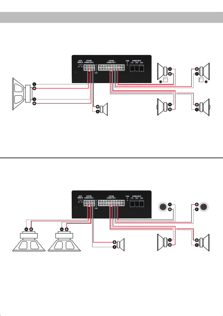
29
Congurationexamples
7-channel application with center speaker and 2 x 2 Ohms subwoofer
2-way passive system + coaxial system + center speaker + subwoofer with dual voice coil
2 x 2 Ohms subwoofer
7-channel application with 2-way active system, center speaker and two 1 x 2 Ohms subwoofers
Tweeters + mid-woofers + center speaker + two subwoofers with single voice coil
Center speaker
VC = Voice coil
Center speaker
Left Right
Tweeters
Left Right
VC 2
VC 1
1 x 2 Ohms subwoofers
Left Right
Front
Left Right
Rear
Mid-woofers
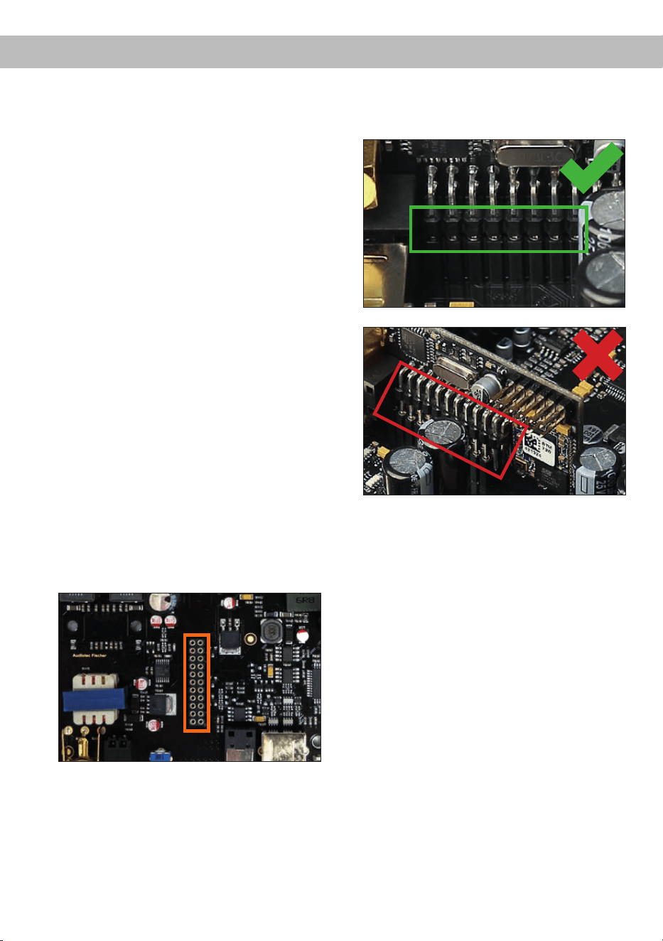
30
Installation of a MATCH Extension Card
It is possible to extend the functionality of the
MATCH UP 7DSP amplier by adding further inter-
faces like a Bluetooth
®
Audio Streaming module, a
High Resolution Audio USB soundcard etc.
To install a MATCH Extension Card it is necessary
to remove the side panel of the UP 7DSP and re-
place it by the new side panel that comes with the
MEC module.
Attention: Install the MEC module only in the
designated device and its specic slot. Using
the MEC module in other devices or slots can
result in damage of the MEC module, the ampli-
er,theheadunit/carradioorotherconnected
devices!
Read in the following the steps how to install a MEC
module:
1. First disconnect all cables from the device.
2. Dismantle the side panel where the USB input
is located by removing the Phillips screws.
3. Pull out the bottom plate.
4. Prepare the module for installing it into the de-
vice. Any further mounting information will be
found in the instruction manual of the respective
MEC module.
5. Insert the MEC module into the specic slot of
the device which is marked in the following pic-
ture.
6. Make sure that the MEC module is installed
properly and all pins are fully inserted into the
socket.
7. Reinsert the bottom plate and x the new side
panel which is delivered with the MEC module
with the Phillips screws.
8. Bolt the MEC module to the side panel. Pre-
cise mounting information will be found in
the instruction manual of the respective MEC
module.
9. Reconnect all cables to the device.
10. Turn on the amplier. The MEC module is auto-
matically detected by the device and the Status
LED of the MEC module lights up green.
11. Now you are able to congure the MEC module
in the DSP PC-Tool software.

31
Technical Data
Output power RMS / max.
- @ 4 Ohms ................................................................... 5 x 65 / 130 Watts (Front / Rear / Center channels)
- Subwoofer output @ 2 Ohms ...................................... 2 x 160 / 320 Watts
Amplier technology ...................................................... Class HD
Inputs ............................................................................. 4 x Highlevel speaker input
1 x Optical SPDIF (12 - 96 kHz)
1 x MEC
1 x Remote In
Input sensitivity .............................................................. Highlevel 5 - 11 Volts
Input impedance highlevel ............................................. 13 Ohms
Outputs .......................................................................... 7 x Speaker output
1 x RCA / Cinch
2 x Remote Out
Output voltage RCA / Cinch........................................... 3 Volts RMS
Frequency response ...................................................... 20 Hz - 22,000 Hz
DSP resolution ............................................................... 64 Bit
DSP power .................................................................... 295 MHz (1.2 billion MAC operations/second)
Sampling rate ................................................................ 48 kHz
DSP type ....................................................................... Audio signal processor
Signal converters ........................................................... A/D: BurrBrown
D/A: BurrBrown
Signal-to-noise ratio digital input ................................... 105 dB (A-weighted)
Signal-to-noise ratio analog input .................................. 103 dB (A-weighted)
Distortion (THD) ............................................................. < 0.03 %
Damping factor .............................................................. > 100
Operating voltage .......................................................... 10.5 - 16 Volts (max. 5 sec. down to 6 Volts)
Current draw .................................................................. 450 mA
Max. remote output current ........................................... 500 mA
Fuse............................................................................... 2 x 25 A LP-Mini-fuse (APS)
Additional features ......................................................... Class HD technology with dynamically controlled
power supply, ADEP.3 circuit, Start-Stop capabil-
ity, Control Input, USB, MEC slot, Auto Remote
switch, galvanically isolated Line Out
Dimensions (H x W x D) ................................................ 46 x 130 x 153 mm / 1.81 x 5.12 x 6.02”
The limited warranty comply with legal regulations.
Failures or damages caused by overload or im-
proper use are not covered by the warranty. Please
return the defective product only with a valid proof
of purchase and a detailed malfunction description.
Technical specications are subject to change!
Errors are reserved! For damages on the vehicle
and the device, caused by handling errors of the
device, we can’t assume liability. These devices are
certied for the use in vehicles within the European
Community (EC).
Warranty Disclaimer
Note:
“The Bluetooth
®
word mark and logos are registered trademarks owned by Bluetooth SIG, Inc. and any use of such marks by
Audiotec Fischer GmbH is under license. Other trademarks and trade names are those of their respective owners.”

Audiotec Fischer GmbH
Hünegräben 26 · 57392 Schmallenberg · Germany
Tel.: +49 2972 9788 0 · Fax: +49 2972 9788 88
E-mail: match@audiotec-scher.com · Internet: www.audiotec-scher.com