10-Kanal Upgrade-Verstärker mit integriertem
11-Kanal 64 Bit DSP für universelle Anwendungen
10-channel upgrade amplier with integrated
11-channel 64 Bit DSP for universal applications
deutsch / english
UP 10DSP
MK2
UPGRADE

2
Sehr geehrter Kunde,
wir gratulieren Ihnen zum Kauf dieses hochwertigen
MATCH Verstärkers mit integriertem DSP.
Audiotec Fischer setzt mit dem MATCH
UP 10DSP MK2
neue Maßstäbe im Bereich der
Verstärkertechnik. Dabei protieren Sie als Kunde
direkt von unserer mehr als 35-jährigen Erfahrung in der
Forschung und Entwicklung von Audiokomponenten.
Dieser Upgrade-Verstärker wurde von uns nach
neuesten technischen Erkenntnissen entwickelt und
zeichnet sich durch hervorragende Verarbeitung sowie
durch die praxisgerechte Anwendung ausgereifter
Technologien aus.
Viel Freude an diesem Produkt wünscht Ihnen das
Team von
AUDIOTEC FISCHER
Allgemeines zum Einbau von MATCH-Kompo-
nenten
Um alle Möglichkeiten des Produktes optimal aus-
schöpfen zu können, lesen Sie bitte sorgfältig die
nachfolgenden Installationshinweise. Wir garantie
-
ren, dass jedes Gerät vor Versand auf seinen ein-
wandfreien Zustand überprüft wurde.
Vor Beginn der Installation unterbrechen Sie den
Minusanschluss der Autobatterie.
Wir empfehlen Ihnen, die Installation von einem Ein
-
bauspezialisten vornehmen zu lassen, da der Nach-
weis eines fachgerechten Einbaus und Anschlusses
des Gerätes Voraussetzung für die Garantielei
-
stungen sind.
Installieren Sie Ihren Verstärker an einer trockenen
Stelle im Auto und vergewissern Sie sich, dass der
Verstärker am Montageort genügend Kühlung erhält.
Montieren Sie das Gerät nicht in zu kleine, abge
-
schlossene Gehäuse ohne Luftzirkulation oder in der
Nähe von wärmeabstrahlenden Teilen oder elektro
-
nischen Steuerungen des Fahrzeuges.
Im Sinne der Unfallsicherheit muss der Verstär
-
ker professionell befestigt werden. Verwenden Sie
hierzu die zwei im Lieferumfang enthaltenen Mon
-
tagebleche. Diese werden mit jeweils zwei kurzen
Schrauben (im Lieferumfang enthalten) an der Un
-
terseite des Verstärkers befestigt. Wenn Sie den
Verstärker mittels Schrauben an der Karosserie be
-
festigen, so vergewissern Sie sich, dass die Monta-
geäche genügend Halt bietet und keine elektrischen
Kabel und Komponenten, hydraulische Bremslei
-
tungen, der Benzintank etc. dahinter verborgen sind.
Diese könnten sonst beschädigt werden. Achten Sie
bitte darauf, dass sich solche Teile auch in der dop
-
pelten Wandverkleidung verbergen können.
Allgemeines zum Anschluss des MATCH
UP 10DSP MK2 Verstärkers
Der Verstärker darf nur in Kraftfahrzeuge eingebaut
werden, die den 12 V-Minuspol an Masse haben. Bei
anderen Systemen können der MATCH Verstärker
und die elektrische Anlage des Kfz beschädigt wer
-
den. Die Plusleitung für die gesamte Anlage sollte
in einem Abstand von max. 30 cm von der Batterie
mit einer Hauptsicherung abgesichert werden. Der
Wert der Sicherung errechnet sich aus der maxima
-
len Stromaufnahme der Car-Hi Anlage und dem
verwendeten Leitungsquerschnitt.
Verwenden Sie zur Verbindung des MATCH
UP 10DSP MK2 Verstärkers ausschließlich die
beiliegenden Anschlusskabel oder einen optio
-
nal erhältlichen MATCH-Kabelbaum! Die Verwen-
dung anderer Kabel kann zu Schäden an ihrer
Anlage führen. Die Sicherungen im Verstärker
dürfen nur mit den gleichen Werten (2 x 25 A)
ersetzt werden, um eine Beschädigung des Ge
-
rätes zu verhindern. Höhere Werte können zu ge-
fährlichen Folgeschäden führen!
Die Kabelverbindungen müssen so verlegt sein,
dass keine Klemm-, Quetsch- oder Bruchgefahr be
-
steht. Bei scharfen Kanten (Blechdurchführungen)
müssen alle Kabel gegen Durchscheuern gepolstert
sein. Ferner darf das Versorgungskabel niemals mit
Zuleitungen zu Vorrichtungen des Kfz (Lüftermo
-
toren, Brandkontrollmodulen, Benzinleitungen etc.)
verlegt werden.
Herzlichen Glückwunsch!
Allgemeine Hinweise
3
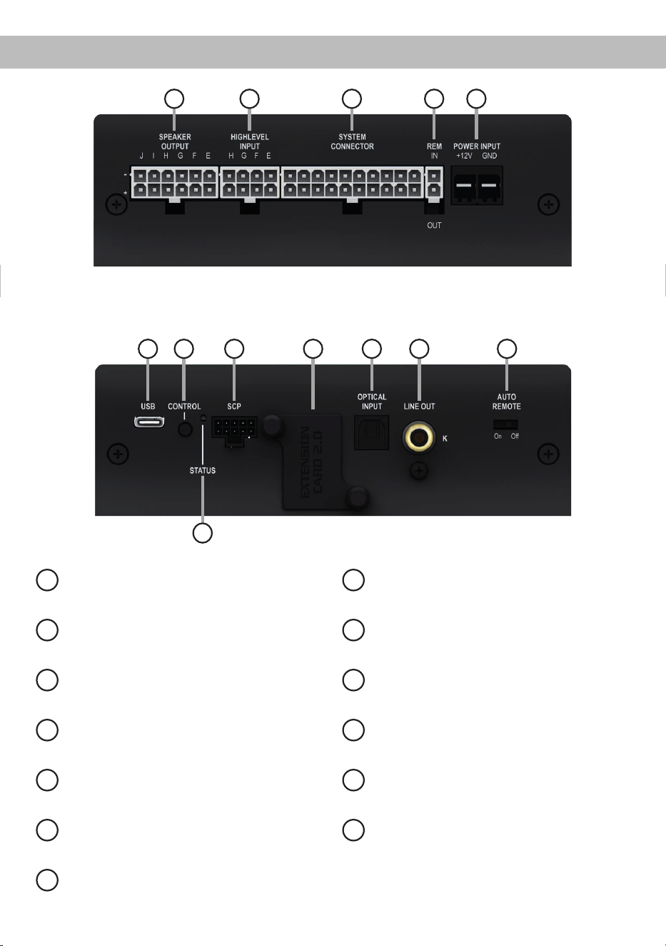
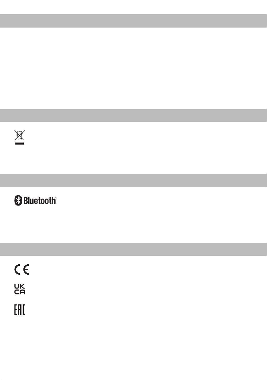
deAnschluss- und Bedienelemente
1 2 3 4 5
1
Lautsprecherausgänge E - J
Seite 7, Punkt 4
2
Highlevel-Lautsprechereingänge E - H
Seite 7, Punkt 3
3
System Connector Eingang
Seite 7, Punkt 2
4
Remote-Anschlüsse
Seite 8, Punkt 7
5
Anschluss Stromversorgung
Seite 9, Punkt 8
6
USB-C Eingang
Seite 9, Punkt 9
7
Control Taster
Seite 12, Punkt 2
8
SCP (Smart Control Port)
Seite 12, Punkt 3
9
Extension Card 2.0 Slot
Seite 18
10
Optischer Digitaleingang
Seite 8, Punkt 5
11
Vorverstärkerausgang
Seite 11, Punkt 13
12
Auto Remote-Schalter
Seite 8, Punkt 6
13
Status LED
Seite 12, Punkt 1
6 7 8 9 10 11
13
12
4
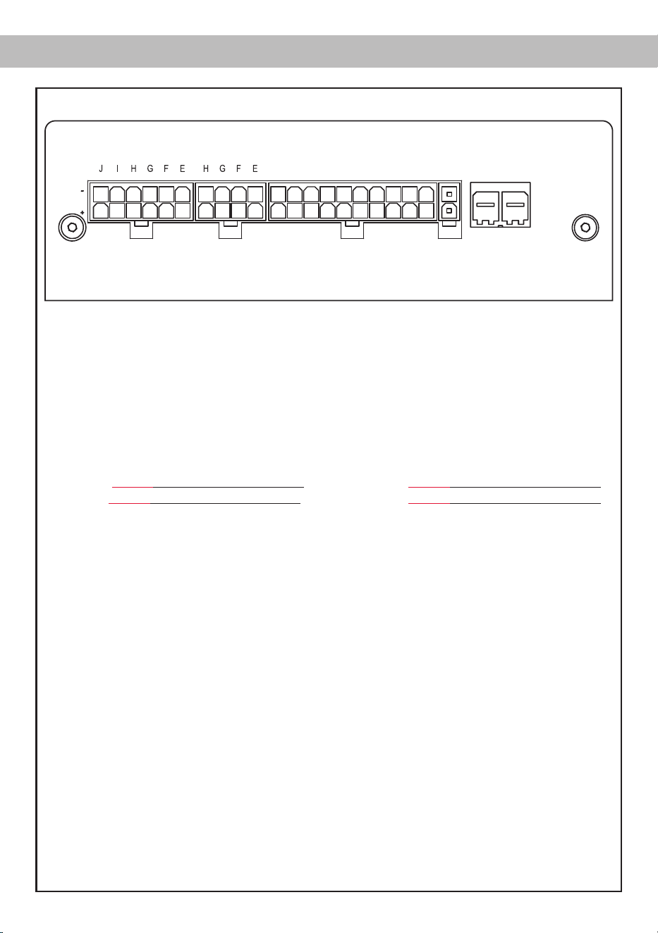
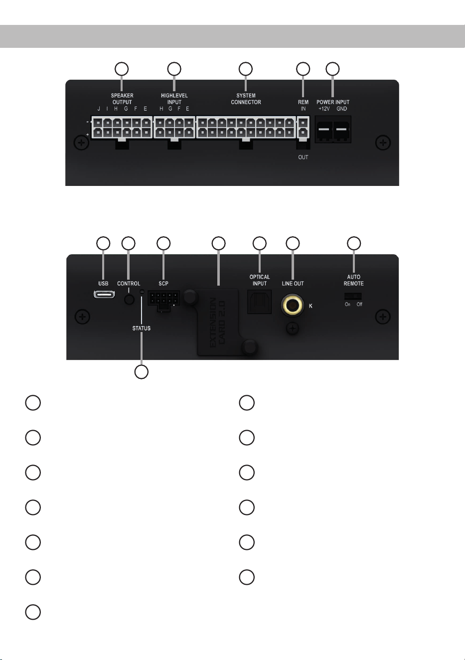
Abb. 1: Pinbelegung UP 10DSP MK2
Hardware-Konguration
System Connector
1. Highlevel-Lautsprechereingang hinten links (-) / C
2. Highlevel-Lautsprechereingang vorne links (-) / A
3. Highlevel-Lautsprechereingang vorne rechts (-) / B
4. Highlevel-Lautsprechereingang hinten rechts (-) / D
5. Lautsprecherausgang hinten rechts (-) / D
6. Lautsprecherausgang hinten links (-) / C
7. Lautsprecherausgang vorne rechts (-) / B
8. Lautsprecherausgang vorne links (-) / A
9. Masse* / Wichtig: Pin darf nicht belegt werden!
10. Masse*/ Wichtig: Pin darf nicht belegt werden!
11. Highlevel-Lautsprechereingang hinten links (+) / C
12. Highlevel-Lautsprechereingang vorne links (+) / A
13. Highlevel-Lautsprechereingang vorne rechts (+) / B
14. Highlevel-Lautsprechereingang hinten rechts (+) / D
15. Lautsprecherausgang hinten rechts (+) / D
16. Lautsprecherausgang hinten links (+) / C
17. Lautsprecherausgang vorne rechts (+) / B
18. Lautsprecherausgang vorne links (+) / A
19. +12 Volt* / Wichtig: Pin darf nicht belegt werden!
20. +12 Volt* / Wichtig: Pin darf nicht belegt werden!
Highlevel Input E - H
21. Highlevel-Lautsprechereingang Kanal H (-)
22. Highlevel-Lautsprechereingang Kanal G (-)
23. Highlevel-Lautsprechereingang Kanal F (-)
24. Highlevel-Lautsprechereingang Kanal E (-)
25. Highlevel-Lautsprechereingang Kanal H (+)
26. Highlevel-Lautsprechereingang Kanal G (+)
27. Highlevel-Lautsprechereingang Kanal F (+)
28. Highlevel-Lautsprechereingang Kanal E (+)
* Nicht belegt beim beiliegenden System Connector Anschlusskabel.
HIGHLEVEL
INPUT
POWER INPUT
SPEAKER
OUTPUT
+12V GNDIN
REM
OUT
SYSTEM
CONNECTOR
403938373635 28272625 20191817161514131211
343332313029 24232221 10987654321
Speaker Output E - J
29. Subwooferausgang 2 (-) / J
30. Subwooferausgang 1 (-) / I
31. Lautsprecherausgang H (-)
32. Lautsprecherausgang G (-)
33. Lautsprecherausgang F (-)
34. Lautsprecherausgang E (-)
35. Subwooferausgang 2 (+) / J
36. Subwooferausgang 1 (+) / I
37. Lautsprecherausgang H (+)
38. Lautsprecherausgang G (+)
39. Lautsprecherausgang F (+)
40. Lautsprecherausgang E (+)

5
de
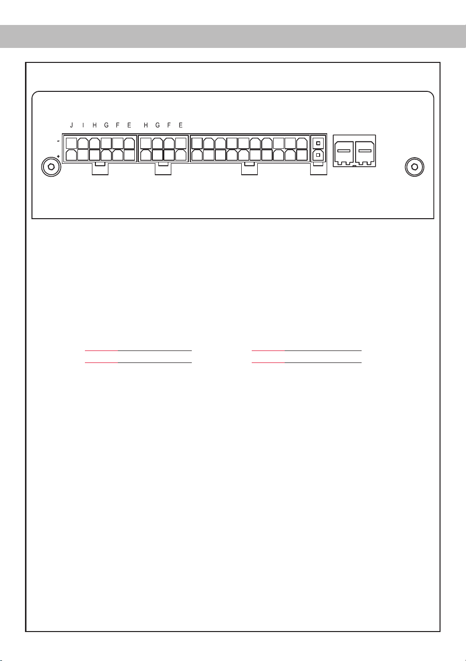
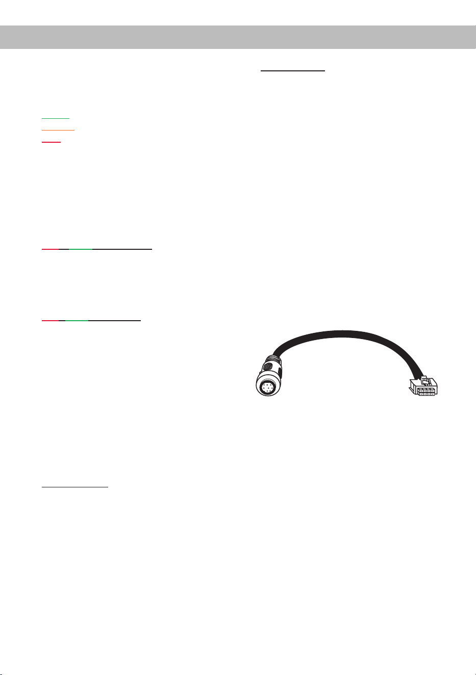
Abb. 2: Übersicht Anschlusskabel
1
System Connector Anschlusskabel
2
Speaker Output E - J Anschlusskabel
3
Highlevel Input E - H Anschlusskabel
4
Remote (REM IN / OUT) Anschlusskabel
1 2 3
Abb. 3: Belegung Power Input Stecker
Steckeroberseite
A
+12 V – Zum Anschluss des +12 V Versorgungskabels
B
GND – Zum Anschluss des Massekabels
A
B
4
6
Kongurieren Sie den MATCH UP 10DSP MK2 in
der nachfolgenden Reihenfolge
Achtung: Für die Durchführung der nachfolgenden
Schritte werden Spezialwerkzeuge und Fachwissen
benötigt. Um Anschlussfehler und Beschädigungen
zu vermeiden, fragen Sie im Zweifelsfall Ihren Ein-
bauspezialisten und beachten Sie zwingend die
allgemeinen Anschluss- und Einbauhinweise (siehe
Seite 2).
1. Einstellung des Eingangsspannungsbe-
reichs für die Highlevel-Lautsprecherein-
gänge G & H
Die UP 10DSP MK2 ist mit zwei hochbelast-
baren Highlevel-Lautsprechereingängen bis zu
32 V ausgestattet. Dies sind die Kanäle G & H.
Bevor Sie beginnen, den Eingangsspannungs-
bereich („Voltage Range“) der Signal eingänge
anzupassen, beachten Sie bitte die folgenden
Hinweise. Diese Einstellung ist nur erforderlich,
wenn Sie Geräte aus den folgenden Kategorien
anschließen:
- Werkseitig installierte Soundsystem-Ver-
stärker mit bis zu zwei Leistungskanälen
mit mehr als 50 W RMS Ausgangsleistung
Für Standardanwendungen wie den Anschluss
von:
- Original-Radios
- Werkseitig installierte Soundsystem-Ver-
stärker mit weniger als 50 W RMS Aus-
gangsleistung
ist diese Einstellung nicht erforderlich. In diesem
Fall können Sie direkt auf Seite 7 mit Punkt 2
fortfahren. Einstellungsbeispiele zur Eingangs-
empndlichkeit nden Sie auf Seite 11.
So stellen Sie den Eingangsspannungsbe-
reich ein:
a. Verstärker önen
Entfernen Sie das Seitenblech mit dem USB-
C Eingang, indem Sie die drei Kreuzschlitz-
schrauben lösen und das Bodenblech zur
Seite herausziehen.
b. Ausgangsspannung der Signalquelle er-
mitteln
Wir empfehlen, die maximale Ausgangsspan-
nung mithilfe eines geeigneten Messgeräts
zu ermitteln oder sich an Ihren autorisierten
MATCH Fachhändler zu wenden. Wenn Sie
unsicher sind, empfehlen wir, den Jumper
auf „High Voltage Range“ einzustellen (Input
G - H 32 V), um mögliche Schäden am Gerät
zu vermeiden. Hierfür muss der Jumper auf
die werkseitig unbenutzte Stiftleiste umge-
steckt werden, wie in Abbildung 2 gezeigt.
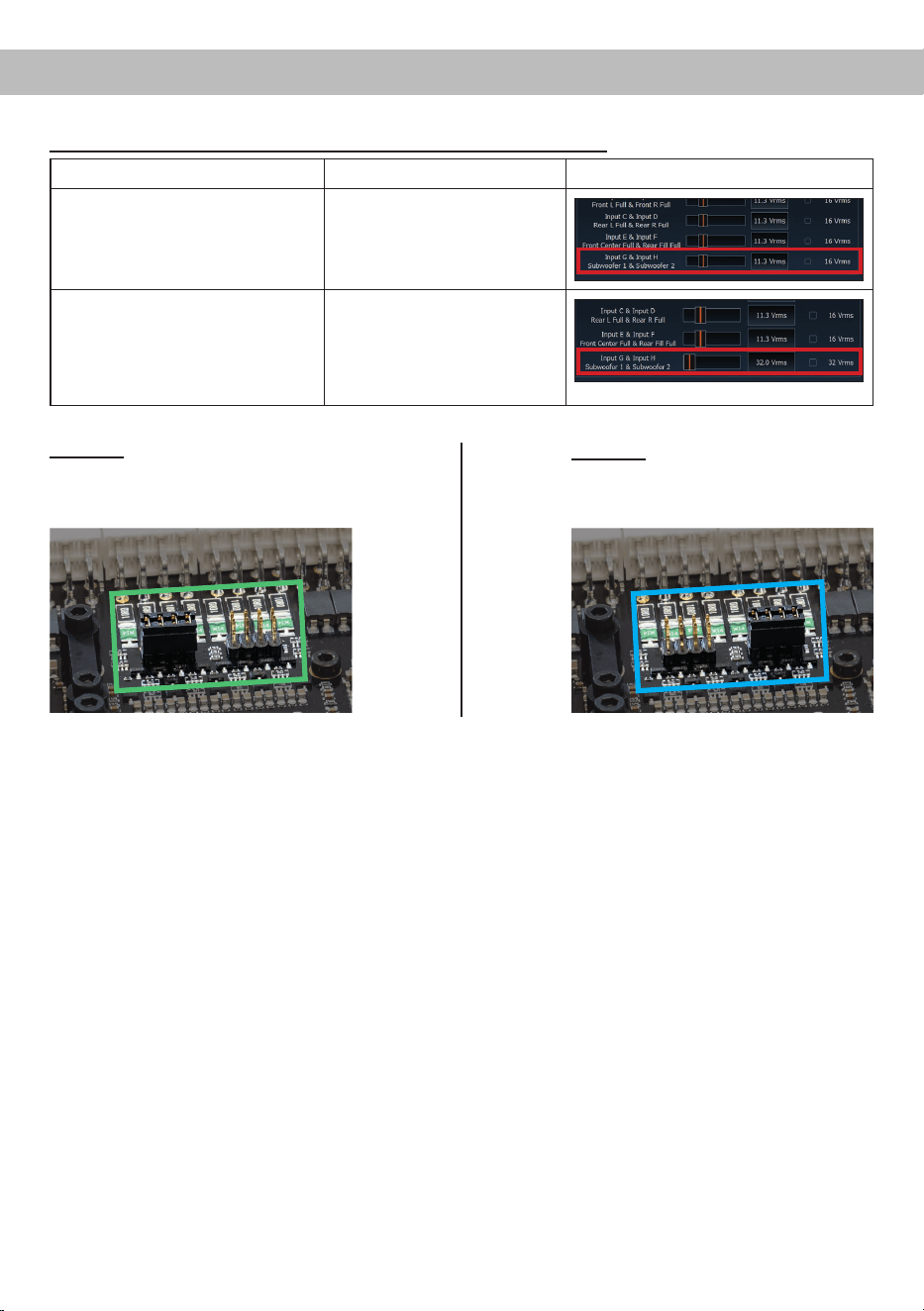
c. Jumper auf den entsprechenden Span-
nungsbereich setzen
Um die Position des Jumpers zu ändern, zie-
hen Sie ihn einfach nach oben ab und ste-
cken ihn in die gewünschte Position. Achten
Sie darauf, dass der Jumper vollständig und
ohne Versatz eingesteckt ist.
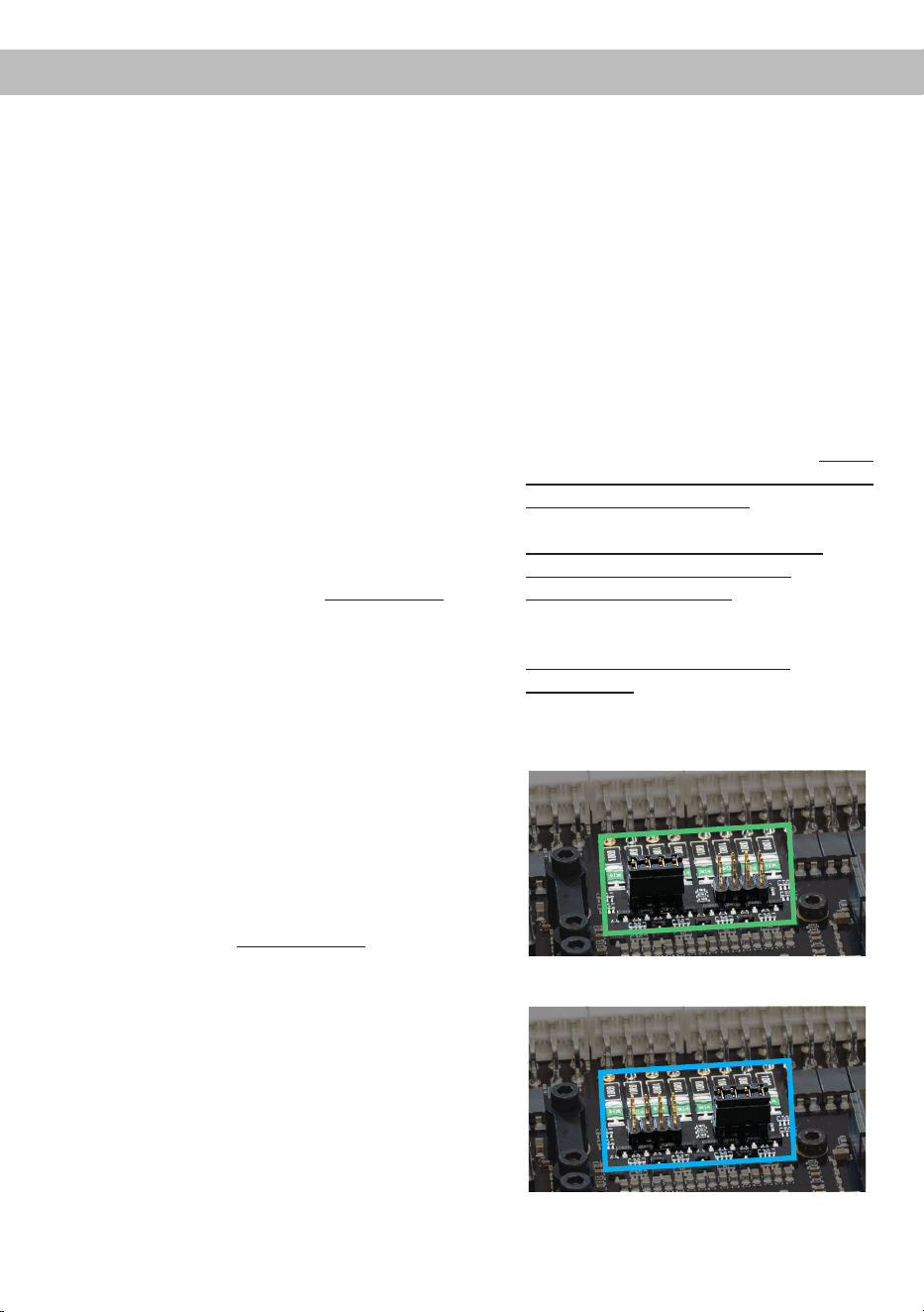
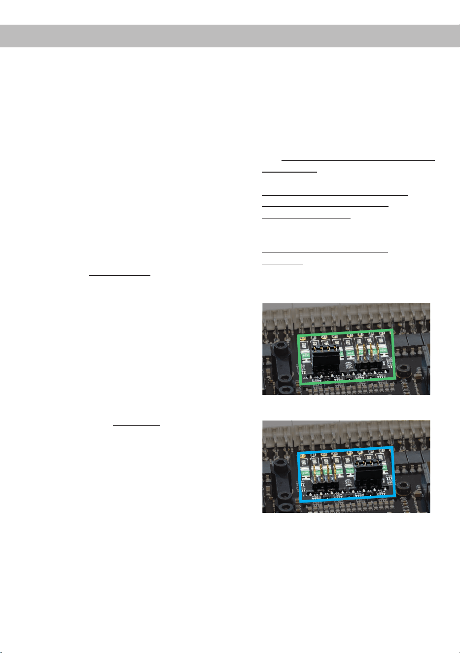
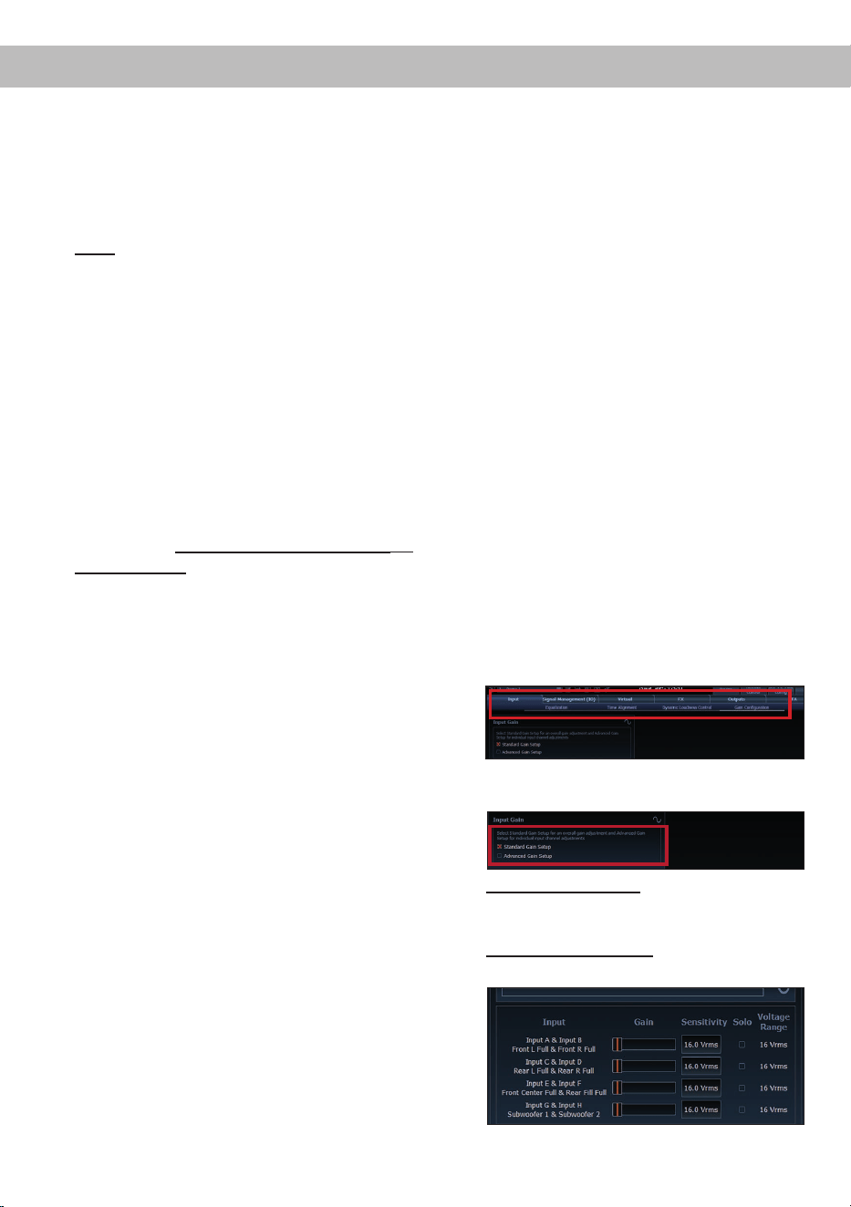
Übersicht Jumper-Steckpositionen:
Low Voltage Range Konguration
( werkseitig / siehe Abb. 1):
Wertebereich: 4 - 16 Volt
High Voltage Range Konguration
(siehe Abb.2):
Wertebereich: 8 - 32 Volt
Abbildung 1:
Abbildung 2:
d. Verstärker wieder zusammenbauen
Hardware-Konguration

7
de
2. Anschluss des System Connector
1. Anschluss der Highlevel-Lautsprecherein-
gänge A - D: Die Highlevel-Lautsprecherein-
gänge (Seite 4, Abb. 1, Nr. 1 - 4 und Nr. 11
- 14) können mit Hilfe des beiliegenden
MATCH Anschlusskabels direkt mit den
Lautsprecherausgängen des Werks- bzw.
Nachrüstradios verbunden werden. Dabei
müssen nicht zwingend alle Eingänge be-
legt werden. Es ist ausreichend, zwei der
vier Highlevel-Lautsprechereingänge zu be-
legen. Mit Hilfe der DSP PC-Tool Software
können die Eingangssignale auf die 11 Aus-
gangskanäle des Verstärkers individuell auf-
geteilt werden.
Achten Sie bitte auf eine korrekte Polung!
Wenn Sie einen oder mehrere Anschlüsse
verpolen, kann dadurch die Funktion des
Verstärkers beeinträchtigt werden. Bei Ver-
wendung dieses Eingangs muss der Remo-
te-Eingang (REM IN) nicht belegt werden, da
sich der Verstärker automatisch einschaltet,
sobald ein Lautsprechersignal anliegt.
2. Anschluss der Lautsprecherausgänge A - D:
Die Lautsprecherausgänge (Seite 4, Abb. 1
Nr. 5 - 8 und Nr. 15 - 18) können mit Hilfe
des beiliegenden MATCH Anschlusskabels
direkt mit den Lautsprecherleitungen verbun-
den werden. Verbinden Sie niemals die Laut-
sprecherleitungen mit der Kfz-Masse (Fahr-
zeugkarosserie). Dies kann Ihren Verstärker
zerstören. Achten Sie darauf, dass alle Laut-
sprechersysteme phasenrichtig angeschlos-
sen sind, d.h. Plus zu Plus und Minus zu
Minus. Vertauschen von Plus und Minus hat
einen Totalverlust der Basswiedergabe zur
Folge. Der Pluspol ist bei den meisten Laut-
sprechern gekennzeichnet. Die Impedanz
pro Kanal darf nicht unter 3 Ohm* liegen, da
sonst die Schutzschaltung des Verstärkers
aktiviert wird.
Achtung: Verwenden Sie zum Anschluss
ausschließlich das mitgelieferte System
Connector Anschlusskabel (Seite 5, Abb. 2)
oder einen passenden Kabelbaum aus dem
MATCH Zubehörprogramm.
3. Optional: Anschluss der Highlevel-Laut-
sprechereingänge E - H
Die Highlevel-Lautsprechereingänge E - H
können direkt mit den Lautsprecherausgän-
gen des Werks- bzw. Nachrüstradios mit Hilfe
des beiliegenden Anschlusskabels verbunden
werden (Seite 4, Abb. 1, Nr. 21 - 28). Achten
Sie bitte auf eine korrekte Polung! Wenn Sie
einen oder mehrere Anschlüsse verpolen,
kann dadurch die Funktion des Verstärkers
beeinträchtigt werden. Die Kanäle G & H kön-
nen darüber hinaus auch an leistungsstärkere
werkseitig installierte Soundsystem-Verstärker
angeschlossen werden, sofern zuvor der Ein-
gangsspannungsbereich gemäß Punkt 1 auf
Seite 6 angepasst wurde. Bei Verwendung die-
ses Eingangs muss der Remote-Eingang (REM
IN / Seite 3, Punkt 4) nicht belegt werden, da
sich der Verstärker automatisch einschaltet, so-
bald ein Lautsprechersignal anliegt.
Achtung: Verwenden Sie zum Anschluss aus-
schließlich das mitgelieferte Anschlusskabel mit
dem 8-poligen Stecker und den oenen Kabel-
enden (Seite 5, Abb. 2) oder einen passenden
Kabelbaum aus dem MATCH Zubehörpro-
gramm.
4. Optional: Anschluss der Lautsprecheraus-
gänge E - J
An die Lautsprecherausgänge können mit Hil-
fe des beiliegenden MATCH Anschlusskabels
Lautsprechersysteme sowie an die zwei Leis-
tungs-Kanäle I & J Subwoofer angeschlossen
werden (Seite 4, Abb. 1, Nr. 29 - 40). Verbinden
Sie die Lautsprecherleitungen niemals mit der
Kfz-Masse (Fahrzeugkarosserie). Dies kann
Ihren Verstärker zerstören. Achten Sie darauf,
dass alle Lautsprechersysteme phasenrichtig
angeschlossen sind, d.h. Plus zu Plus und Mi-
nus zu Minus. Vertauschen von Plus und Minus
hat einen Totalverlust der Basswiedergabe zur
Folge. Der Pluspol ist bei den meisten Laut-
sprechern gekennzeichnet. Die Lautsprecher-
impedanz darf bei den Kanälen E bis H nicht
unter 3 Ohm* und bei den Kanälen I und J nicht
unter 2 Ohm liegen. Wird dieser Wert unter-
schritten, aktiviert sich die Schutzschaltung des
Verstärkers.
Achtung: Verwenden Sie zum Anschluss aus-
*Gleichstromwiderstand min. 3,0 Ohm

8
schließlich das mitgelieferte Anschlusskabel
mit dem 12-poligen Stecker und den oenen
Kabel enden (Seite 5, Abb. 2) oder einen pas-
senden Kabelbaum aus dem MATCH Zubehör-
programm.
5. Anschluss einer digitalen Signalquelle im
SPDIF Format
Sofern Sie über eine Signalquelle mit op-
tischem Digitalausgang verfügen, kann diese
an den Verstärker angeschlossen werden. Die
Abtastrate (Sampling Rate) muss zwischen 12 -
96 kHz
liegen
. Das Eingangssignal wird auto-
matisch an die interne Abtastrate angepasst.
Werkseitig ist die manuelle Einschaltung des
Eingangs über eine optionale Fernbedienung
konguriert. Möchten Sie den Eingang auto-
matisch, bei Anliegen eines Audiosignals, ak-
tivieren, können Sie dies in der DSP PC-Tool
Software unter dem Tab „ Signal Management
(IO)“ im Unterpunkt „Source Conguration“ kon-
gurieren.
Die Einschaltautomatik des Verstärkers funktio-
niert bei Verwendung des Digitaleingangs nicht,
so dass der Remote-Eingang (REM IN / Sei-
te 3, Punkt 4) zwingend belegt werden muss.
Wichtig: Das digitale Audiosignal einer Quelle
ist üblicherweise nicht lautstärkegeregelt. Das
bedeutet, dass an den Signalausgängen des
MATCH UP 10DSP MK2 der volle Pegel an-
liegt und die angeschlossenen Verstärker voll
ausgesteuert werden. Dies kann im Extremfall
die Lautsprecher zerstören. Wir raten deshalb
dringend dazu, eine optionale Fernbedienung
zur Einstellung der Lautstärke der digitalen
Signaleingänge zu verwenden!
Hinweis: Der Verstärker kann nur unkompri-
mierte, digitale Stereo PCM-Signale mit einer
Abtastrate zwischen 12 kHz und 96 kHz verar-
beiten.
6. Konguration des Remote-Eingangs
Die Einschaltung der MATCH UP 10DSP MK2
erfolgt automatisch bei Ansteuerung über die
Highlevel-Lautsprechereingänge des System
Connectors und/oder Highlevel Inputs E - H
oder sobald ein Remote-Signal am Remote-
Eingang (REM IN) anliegt. Mit Hilfe des Auto
Remote-Schalters (Seite 3, Punkt 12) kann die
automatische Einschaltung über die Highlevel-
Lautsprechereingänge deaktiviert werden. Dies
sollte vorgenommen werden, wenn es bei-
spielsweise zu Störgeräuschen beim Ein- und
Ausschalten des Verstärkers kommt.
On: Einschaltung über Highlevel-Lautsprecher-
eingänge aktiviert (Werkseinstellung).
O: Einschaltung über Highlevel-Lautsprecher-
eingänge deaktiviert.
Hinweis: Wird die automatische Einschaltung
des Verstärkers deaktiviert, muss der Remote-
Eingang belegt werden. Eine automatische
Einschaltung über den Highlevel-Lautsprecher-
eingang ist dann nicht mehr möglich.
7. Anschluss der Remote-Leitungen
Schließen Sie die Remote-Leitungen aus-
schließlich über das mitgelieferte Anschlusska-
bel mit dem 2-poligen Stecker und den oenen
Kabel enden (Seite 5, Abb. 2) oder einen pas-
senden Kabelbaum aus dem MATCH Zubehör-
programm.
REM IN: Der Remote-Eingang
dient zum Ein-
schalten der UP 10DSP MK2 , sofern die am
System Connector oder Highlevel Input E - H
angeschlossene Signalquelle die automatische
Einschaltung nicht aktiviert oder der Verstärker
bewusst nur über ein Remote-Signal ein- und
ausgeschaltet werden soll.
Dazu muss der Remote-Eingang des Verstär-
kers mit dem Remote-Ausgang des Radios /
der Head Unit verbunden werden.
Somit wird der Verstärker über das Radio ein-
und ausgeschaltet. Es wird dringend davon
abgeraten, den Remote-Eingang des Verstär-
kers über das Zündungsplus des Fahrzeugs zu
steuern, um Störgeräusche beim Ein- und Aus-
schalten zu vermeiden.
Hinweis: Bei Verwendung einer der Highlevel-
Eingänge A - H muss der Remote-Eingang nicht
belegt werden, sofern das angeschlossene
Radio über BTL-Ausgangsstufen verfügt. Wie
Sie die automatische Einschaltung über die
Highlevel-Lautsprechereingänge deaktivieren
können, ist unter Punkt 6 „Konguration des
Remote-Eingangs“ nachzulesen.
REM OUT: Der Remote-Ausgang dient zum
prozessorgesteuerten Einschalten eines am
Line Out angeschlossenen Verstärkers. Ver
-
Hardware-Konguration

9
de
binden Sie dazu den Remote-Ausgang der
UP 10DSP MK2 mit dem Remote-Eingang des
Verstärkers, um diesen über den internen DSP
störungsfrei ein- und auszuschalten.
Dieser Ausgang aktiviert sich automatisch, so
-
bald der Bootvorgang des DSP abgeschlossen
ist. Zudem wird dieser Ausgang bei aktiviertem
„Power Save Mode“ und bei Betriebssoftware-
Updates abgeschaltet.
Wichtig: Verwenden Sie niemals ein anderes
Signal als den Remote-Ausgang, um einen
angeschlossenen Verstärker einzuschalten!
8. Anschluss der Stromversorgung
ACHTUNG: Vor dem Anschluss des +12 V
Versorgungskabels an das Bordnetz muss die
Autobatterie abgeklemmt werden.
Schließen Sie die Stromversorgung aus-
schließlich über den mitgelieferten Power Input
Stecker (Seite 5, Abb. 3) an. Achten Sie unbe-
dingt auf eine korrekte Polarität.
+12 V: Das +12 V Stromkabel ist am Pluspol
der Batterie anzuschließen. Die Plusleitung
sollte in einem Abstand von max. 30 cm von
der Batterie mit einer Hauptsicherung abgesi-
chert werden. Der Wert der Sicherung errech-
net sich aus der maximalen Stromaufnahme
der gesamten Car-Hi Anlage und dem Quer-
schnitt der Stromleitungen (UP 10DSP MK2 =
max. 60 A bei 12 V Bordnetz). Verwenden Sie
bei kurzen Leitungen (< 1 m) einen Querschnitt
von mindestens 6 mm². Bei längeren Leitungen
empfehlen wir einen Querschnitt von 6 mm² bis
10 mm².
GND: Anschluss für die Masseleitung. Das
Massekabel muss an einer nicht isolierten Stel-
le mit dem Kfz-Chassis verbunden werden. Der
Kabelquerschnitt sollte den gleichen Durchmes-
ser wie die Plusleitung haben. Ein nicht ausrei-
chender Massekontakt führt zu unerwünschten
Störgeräuschen und Fehlfunktionen.
9. Anschluss an den Computer & Einschalten
Der Verstärker kann über den USB-C Eingang
(Seite 3, Punkt 6) mit dem Computer verbun-
den und anschließend mit dem DSP PC-Tool
konguriert werden. Verwenden Sie dazu das
beiliegende USB-C Kabel.
Hinweis: Es können keine USB Speichermedi-
en an den Verstärker angeschlossen werden.
Bevor Sie die UP 10DSP MK2 das erste Mal mit
einem Computer verbinden, laden Sie die ak-
tuellste DSP PC-Tool Software (mindestens
Version 6) von unserer Homepage herunter. Es
ist ratsam, regelmäßig nach Updates der Soft-
ware zu schauen, damit das Gerät immer auf
dem aktuellsten Stand ist. Die Software sowie
eine umfangreiche Knowledge Base nden Sie
auf www.audiotec-scher.de.
Es wird dringend empfohlen, die DSP PC-Tool
Knowledge Base vor der ersten Benutzung
durchzulesen, um Komplikationen und Fehler
zu vermeiden.
Wichtig: Stellen Sie sicher, dass der Verstärker
bei der ersten Installation der Software noch
nicht am PC angeschlossen ist. Verbinden Sie
diesen erst, wenn die Software samt der USB-
Treiber vollständig installiert ist.
Im folgenden Abschnitt lesen Sie die wich-
tigsten Schritte zum Anschluss und der ersten
Inbetriebnahme:
1. Laden Sie die DSP PC-Tool Software unter
www.audiotec-scher.de herunter und in-
stallieren Sie diese auf Ihrem Computer.
2. Schließen Sie danach den Verstärker mit
dem beiliegenden USB-C Kabel an den
Computer an. Wenn Sie längere Distanzen
zu überbrücken haben, verwenden Sie bitte
eine aktive USB-Verlängerung mit integrier-
tem Repeater.
3. Schalten Sie erst die UP 10DSP MK2 ein
und starten Sie anschließend die Software.
Sofern die Betriebssoftware des Verstärkers
nicht mehr aktuell ist, wird diese automatisch
aktualisiert.
10. Einstellen der Eingangsempndlichkeit der
analogen Signaleingänge
ACHTUNG: Es ist zwingend notwendig, die
Eingangsempndlichkeit der UP 10DSP MK2
an die Signalquelle anzupassen, um eine best-
mögliche Signalqualität zu garantieren und
Schäden am Verstärker zu vermeiden. Außer-
dem ist es zuvor zwingend erforderlich den
Wertebereich der Eingangskanäle G & H (Vol-
tage Range) an die Ausgangsspannung Ihrer
Signalquelle anzupassen (Seite 6, Punkt 1).
10
Hardware-Konguration
Mit Hilfe der DSP PC-Tool Software muss die
Eingangsempndlichkeit je Kanalpaar optimal
an die Signalquelle angepasst werden.
Die Eingangsempndlichkeit ist ab Werk für alle
Kanäle auf 11 Volt eingestellt. Dieser Wert dient
als optimale Grundeinstellung und muss wie
nachfolgend beschrieben eingestellt werden.
Hinweis: Muten Sie während dieser Prozedur
die Signalausgänge der UP 10DSP MK2 .
1. Verbinden Sie den Verstärker mit einem
Computer und starten Sie die DSP PC-Tool
Software (Seite 9, Punkt 9). Muten Sie an-
schließend alle Signalausgänge in der Soft-
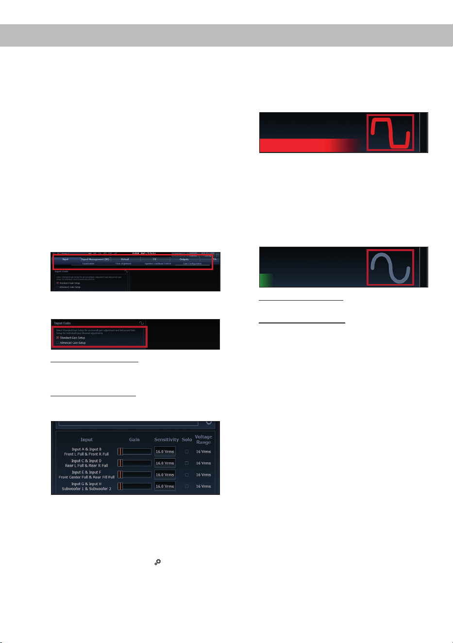
ware. Die Funktion nden Sie im Tab „Input“
im Unterpunkt „Gain Conguration“.
2. Wählen Sie das Setupverfahren zur Einstel-
lung der Eingangsempndlichkeit aus.
Standard Gain Setup: Hier kann die Ein-
gangsempndlichkeit global für alle Kanäle
eingestellt werden.
Advanced Gain Setup: Bei diesem Verfahren
ist eine individuelle Einstellung für die einzel-
nen Kanalpaare möglich.
3. Stellen Sie die Lautstärke Ihres Radios auf
ca. 90 % der Gesamtlautstärke ein und
spielen Sie das dafür speziell entwickelte
„IGS - Input Gain Setup“ Signal ab. Dieses
nden Sie im DSP PC-Tool unter „Audio Test
Tracks“ (Startbildschirm →
).
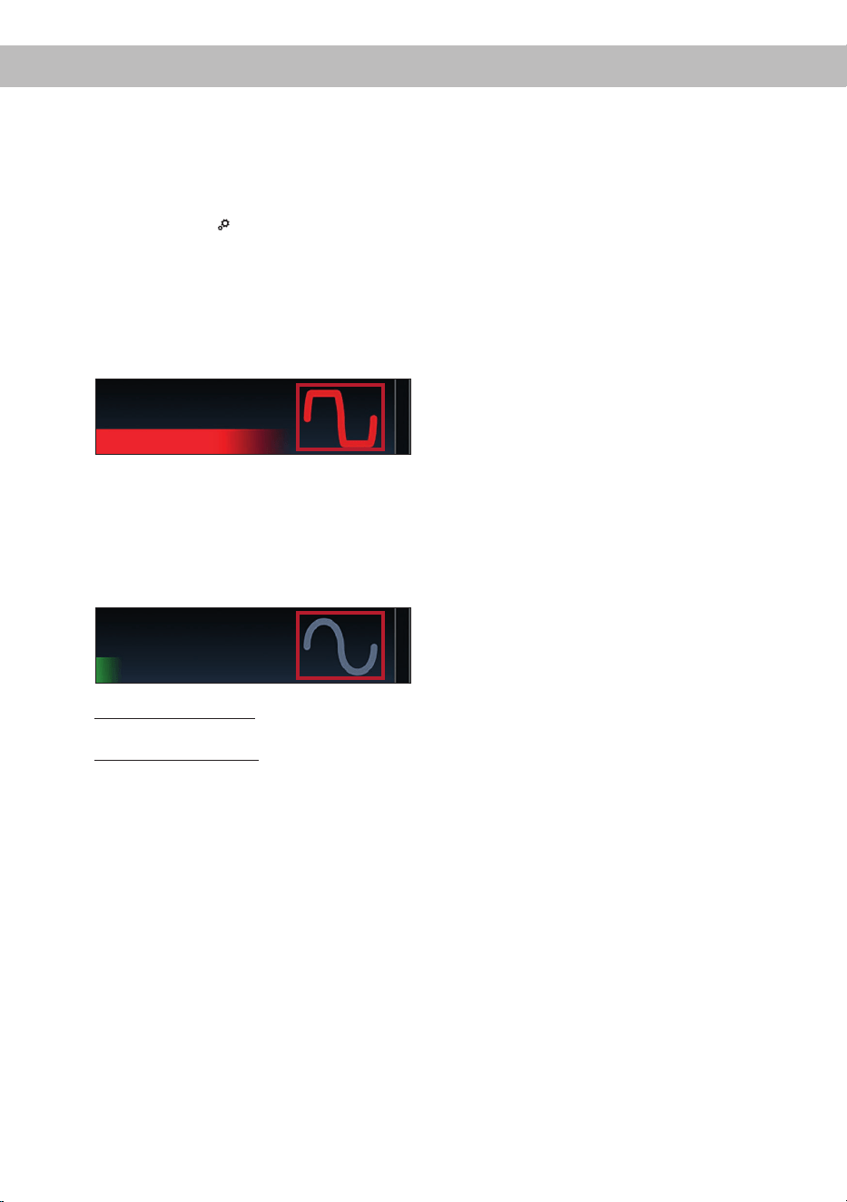
4. In der Regel ist die Clipping-Anzeige im DSP
PC-Tool aus (grau) und leuchtet nur auf,
wenn einer der analogen Signaleingänge
übersteuert wird.
Erhöhen Sie nun die Eingangsempndlich-
keit mit Hilfe des Schiebereglers, bis die
Clipping-Anzeige rot aueuchtet (siehe Mar-
kierung im folgenden Bild).
5. Schieben Sie nun den Regler einen Schritt
zurück, bis die Clipping-Anzeige wieder er-
lischt. Leuchtet die Clipping-LED auch bei
11 Volt dauerhaft rot, ist das Eingangssignal
zu hoch. Bitte wenden Sie sich zur Vermei-
dung von Schäden an einen autorisierten
Fachhändler.
6. Standard Gain Setup: Der Vorgang ist hier-
mit abgeschlossen.
Advanced Gain Setup: Wiederholen Sie die-
sen Vorgang für jedes genutzte Signalein-
gangspaar.
11. Konguration des internen DSPs
WICHTIG: Vor der ersten Inbetriebnahme
wird dringend empfohlen, die grundlegenden
Einstellungen des Verstärkers mit der DSP
PC-Tool Software vorzunehmen, um Beschädi-
gungen am Soundsystem und den angeschlos-
senen Lautsprechern zu vermeiden.
Nach dem Anschluss an einen PC können Sie
den Verstärker frei in der DSP PC-Tool Soft-
ware kongurieren. Nützliche Hinweise zur
korrekten Einstellung entnehmen Sie unserer
Knowledge Base, welche auf unserer Webseite
bereit steht.
Achtung: Es wird dringend empfohlen, zu
Beginn die Lautstärke am Radio auf Minimum
zu drehen und sämtliche Signalausgänge des
UP 10DSP MK2 in der Software zu muten. Spe-
ziell bei Verwendung in vollaktiven Systemen
besteht sonst Zerstörungsgefahr für die Laut-
sprecher.
11
de
12. Optional: Eingangssignal analysieren
Bei Verwendung von Highlevel-Signalen emp-
fehlen wir, das Eingangssignal mit Hilfe des Ad-
vanced Input Signal Analyzers (AISA) der DSP
PC-Tool Software auf werkseitig eingestelltes
Equalizing, Laufzeitkorrektur und Allpass-Filter
zu überprüfen und ggf. zu korrigieren. Infor-
mationen zum AISA nden Sie in der umfang-
reichen Knowledge Base unserer Webseite
www.audiotec-scher.de.
13. Optional: Anschluss des Vorverstärkeraus-
gangs
Der Line Out (Seite 3, Punkt 11) ist ein Mono-
Vorverstärker-Signalausgang zum Anschluss
eines zusätzlichen Verstärkers. Diesen kön-
nen Sie nun mit einem entsprechenden Kabel
(RCA / Cinch-Kabel) mit dem RCA / Cinch-
Eingang des nachgeschalteten Verstärkers
verbinden. Der Ausgang liefert eine maximale
Ausgangsspannung von 3 Volt RMS. Bei Ver-
wendung dieses Ausgangs, ist es zwingend er-
forderlich, den Remote-Ausgang (REM OUT /
Seite 3, Punkt 4) zum Einschalten des ange-
schlossenen Verstärkers zu verwenden, da an-
sonsten Störgeräusche auftreten können.
14. Sound Tuning
Nun können Sie Ihr Sound Setup erstellen. In-
formationen rund um das Sound Tuning nden
Sie in unserer umfangreichen Knowledge Base
auf www.audiotec-scher.de oder kontaktie-
ren Sie Ihren MATCH Fachhändler vor Ort.
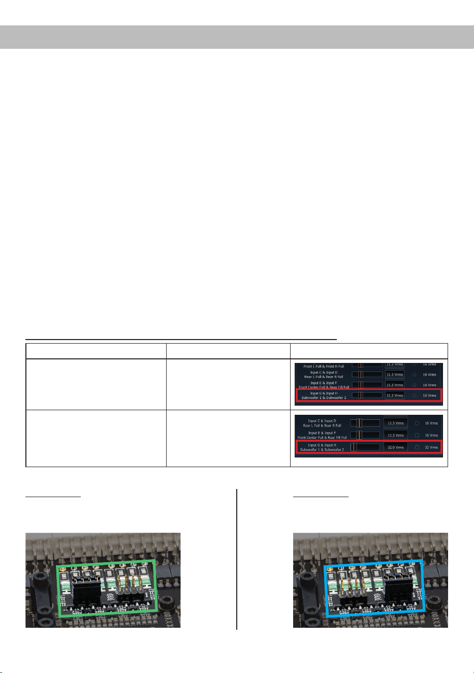
Einstellungsbeispiele für die Eingangsempndlichkeit der Kanäle G & H:
Quelle Jumper position
Input Gain im DSP PC-Tool
OEM-Radio
Bis 25 Watt Sinusleistung pro Kanal
an 4 Ohm bzw. bis 50 Watt Sinuslei-
stung pro Kanal an 2 Ohm
Low Voltage Range (J 1) –
Werkseitige Jumperposition
(siehe Abb. 1)
OEM-Radio mit Zusatzverstärker
Größer 25 Watt bis 200 Watt Sinus-
leistung pro Kanal an 4 Ohm bzw.
bis 100 Watt Sinusleistung pro Kanal
an 8 Ohm
High Voltage Range (J 2)
(siehe Abb. 2)
Abbildung 1:
Wertebereich 4 - 16 Volt
Abbildung 2:
Wertebereich 8 - 32 Volt
Für weitere Anwendungsfälle kontaktieren Sie bitte Ihren MATCH-Fachhändler.
J 2
J 1
12
Weitere Funktionen
1. Status LED
Die Status LED (Seite 3, Punkt 13) zeigt den
Betriebszustand des Verstärkers und dessen
Speichers an.
Grün: Verstärker eingeschaltet und betriebsbereit.
Orange: Power Save Modus aktiv.
Rot: Protection Mode aktiv. Dieser kann unter-
schiedliche Ursachen haben. Der Verstärker ist
mit Schutzschaltungen gegen Über- und Un-
terspannung sowie Überhitzung ausgestattet.
Prüfen Sie in diesem Fall alle Anschlüsse auf
Fehler, wie z.B. Kurzschlüsse oder fehlerhafte
Verbindungen. Ist die Sicherheitsschaltung
der Temperaturüberwachung aktiv, wird der
Remote-Ausgang sowie die Signalausgabe ab-
geschaltet, bis ein sicherer Betrieb wieder ge-
währleistet werden kann.
Rot / grün langsam blinkend: Keine Betriebs-
software auf dem DSP installiert. Verbinden
Sie den Verstärker mit der DSP PC-Tool Soft-
ware und bestätigen Sie das automatische
Update der Betriebssoftware. Die aktuellste
Version des DSP PC-Tools nden Sie auf
www.audiotec-scher.de.
Rot / grün schnell blinkend: Aktuell ausgewähl-
ter Sound Setup-Speicherplatz ist leer. Ein
neues DSP Setup muss über die DSP PC-Tool
Software eingespielt werden oder schalten
Sie auf einen Speicherplatz mit vorhandenem
Sound Setup um.
2. Control Taster
Die UP 10DSP MK2 bietet 10 interne Speicher-
plätze für Sound Setups. Mit Hilfe des Control
Tasters (Seite 3, Punkt 7) lässt sich zwischen
zwei Speicherplätzen umschalten. Diese kön-
nen im DSP PC-Tool festgelegt werden. Zudem
kann durch langes Drücken des Tasters ein
Geräte-Reset durchgeführt werden.
1. Setup-Wechsel: Taster 1 Sek. drücken.
Werkseitig sind die Speicherbereiche eins und
zwei eingestellt. Der Umschaltvorgang wird
durch einmaliges rotes Blinken der Status LED
angezeigt. Alternativ kann zur Umschaltung
die optionale Fernbedienung URC.3 verwen-
det werden. Um zwischen allen internen Spei-
cherplätzen umschalten zu können, ist optio-
nales Zubehör, wie z.B. die Fernbedienungen
DIRECTOR und CONDUCTOR notwendig.
2. Geräte-Reset: Taster länger als 5 Sek. ge-
drückt halten. Durch ein Geräte-Reset wird
der interne Speicher auf die Werkseinstellung
zurückgesetzt! Dies wird durch ein durchge-
hendes rotes Leuchten und grünes schnelles
Dauerblinken der Status LED angezeigt.
Achtung: Nach dem Resetten des Gerätes
kann die UP 10DSP MK2 keine Audiosignale
mehr wiedergeben, bis das Gerät mit Hilfe des
DSP PC-Tools aktualisiert wurde.
3. SCP (Smart Control Port)
Dieser Multifunktionseingang (Seite 3,
Punkt 8) dient zum Anschluss von MATCH
Zubehörprodukten, wie beispielsweise einer
Fernbedienung, mit deren Hilfe diverse Funk-
tionen des Verstärkers gesteuert werden kön-
nen.
Die Funktionalität muss je nach Typ der Fern-
bedienung zuerst im „Device Conguration
Menu“ der DSP PC-Tool Software oder an der
Fernbedienung selbst konguriert werden.
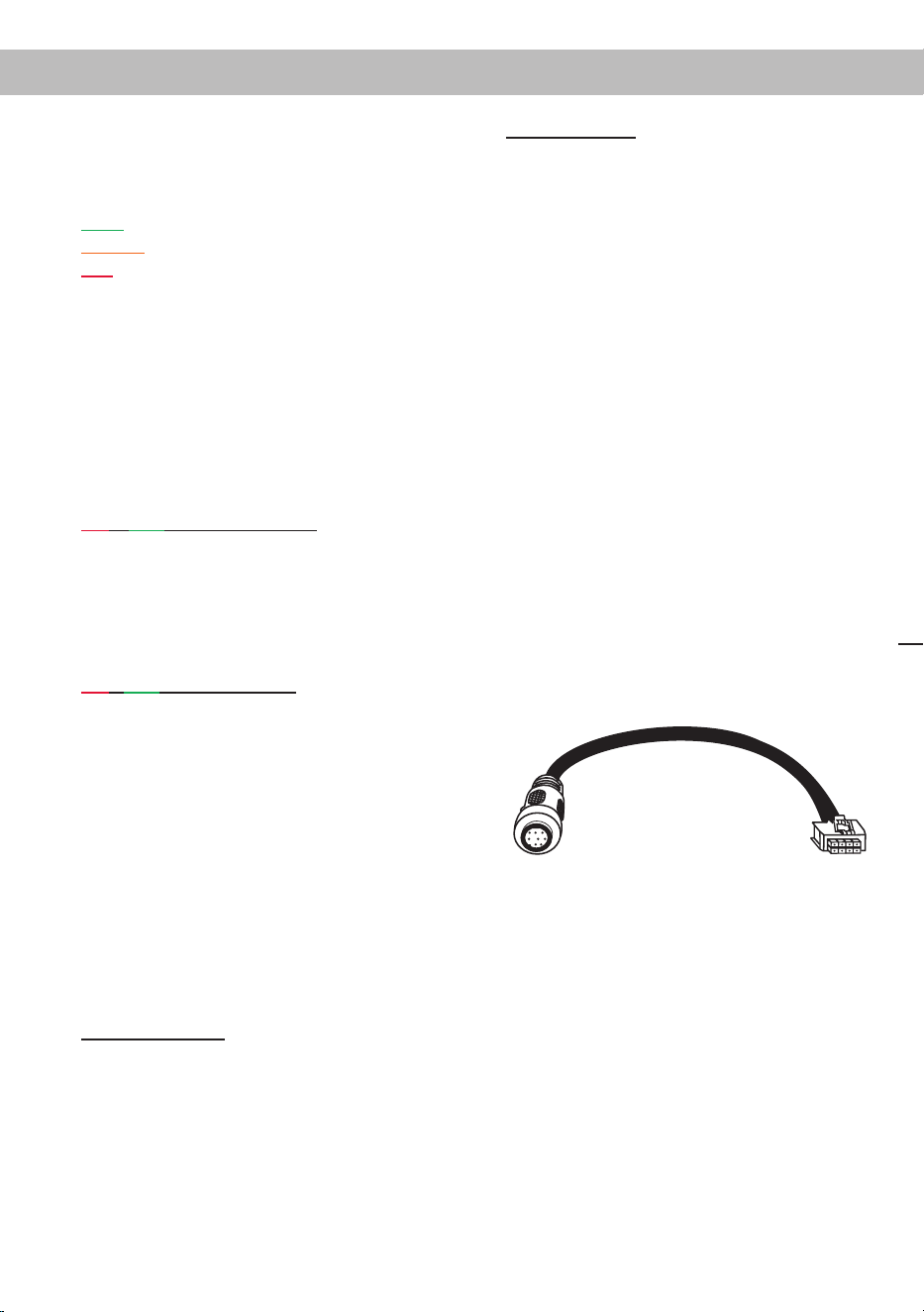
Achtung: Sofern das Zubehörprodukt keinen
SCP-Stecker besitzt, ist ein SCP-to-Control
Input Adapter (Art-Nr. M141313) optional bei
Ihrem Fachhändler erhältlich.
SCP-to-Control Input Adapter
13
Kongurationsbeispiele de
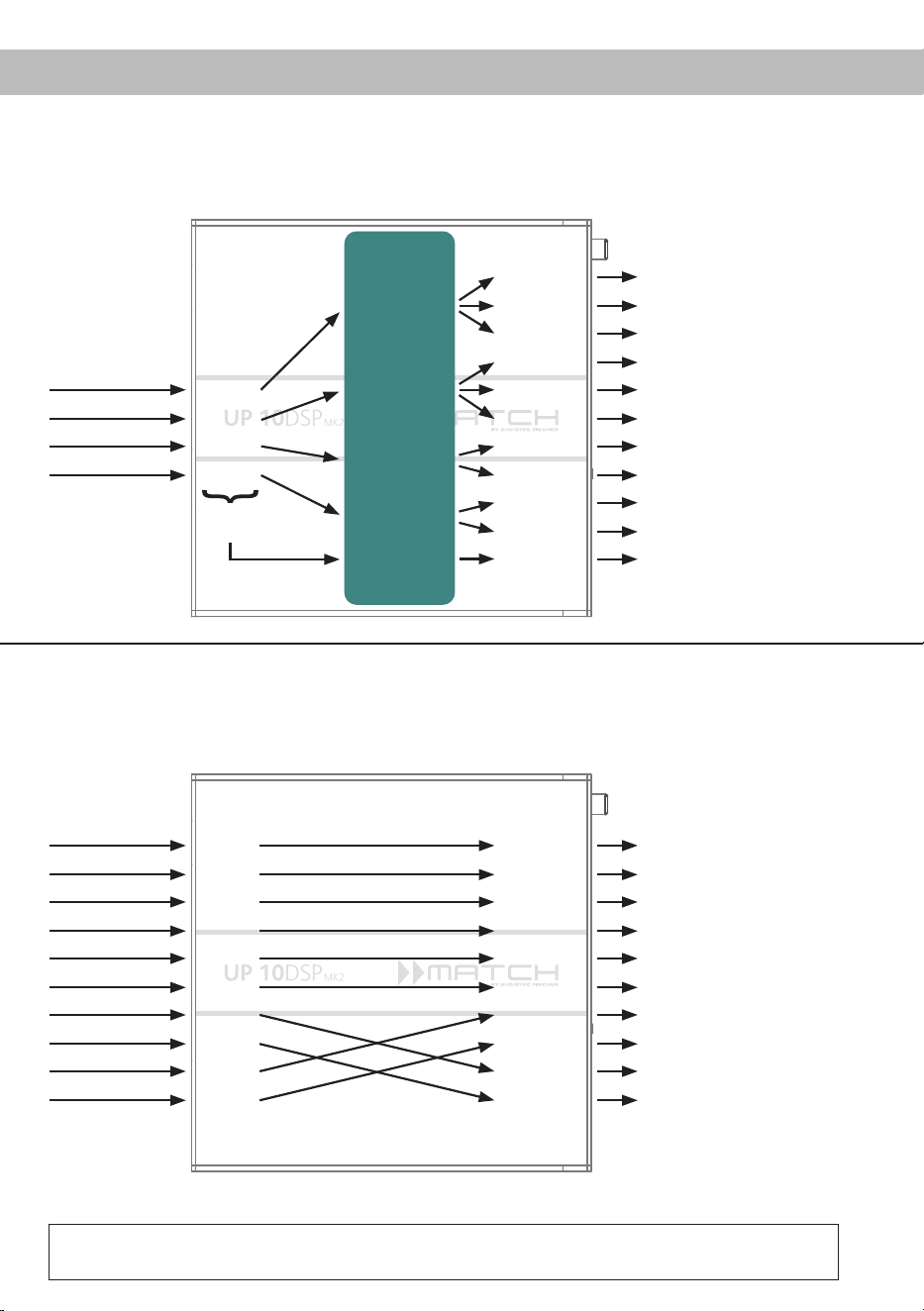
Beispiel 1: Kanalrouting mit Virtual Channel Processing
Vom Autoradio Eingänge Ausgänge Zu den LautsprechernVirtuelle Kanäle
Subwoofer
1
(K)
SFX -
Augmented Bass
Processing
Front L High – Hochtöner VL
Front R High – Hochtöner VR
Front L Mid – Mitteltöner VL
Front R Mid – Mitteltöner VR
Front L Low – Tieftöner VL
Front R Low – Tieftöner VR
Rear L High – Hochtöner HL
Rear R High – Hochtöner HR
Rear L Low – Tieftöner HL
Rear R Low – Tieftöner HR
Subwoofer 1 – Subwoofer
Front L Full
Front R Full
Rear L Full
Rear R Full
Amp Out A
Amp Out C
Amp Out I
Amp Out B
Amp Out D
Amp Out J
Amp Out E
Amp Out G
Amp Out F
Amp Out H
Line Out K
Input A
Input B
Input C
Front L Full (A)
Front R Full (B)
Rear L Full (C)
Rear R Full (D)
Input D
Summen-
signal A bis D
SFX -
Front Processing
SFX -
Front Processing
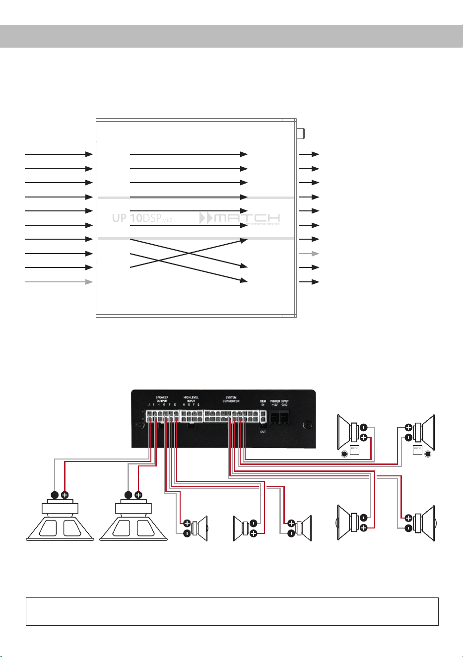
Beispiel 2: 10-Kanal 1 zu 1 Kanalrouting (IOR) z.B.: Vorne 2-Wege vollaktiv / Hinten 2-Wege passiv /
Center 2-Wege vollaktiv / Subwoofer mit Doppelschwingspule – Nur in Verbindung mit der optio-
nalen Extension Card 2.0 – ANALOG IN
Vom Werks-
verstärker
Eingänge Ausgänge Zu den Lautsprechern
Front L High
Front R High
Front L Low
Front R Low
Rear L Full
Rear R Full
Subwoofer L
Subwoofer R
Front Center High
Front Center Low
Front L High – Hochtöner VL
Front R High – Hochtöner VR
Front L Low – Tiefmitteltöner VL
Front R Low – Tiefmitteltöner VR
Rear L Full – 2-Wege Passiv
Rear R Full – 2-Wege Passiv
Front Center High – Hochton Center
Front Center Low – Mittelton Center
Subwoofer 1 – Subwoofer L
Subwoofer 2 – Subwoofer R
Input A
Input B
Input C
Input D
Input E
Input F
Input G*
Input H*
Input I
Input J
Amp Out A
Amp Out B
Amp Out C
Amp Out D
Amp Out E
Amp Out F
Amp Out G
Amp Out H
Amp Out I*
Amp Out J*
* Die hochbelastbaren Signaleingänge G & H (siehe Seite 6, Punkt 1)
werden auf die Subwoofer-Leistungskanäle I & J geroutet.
4-Kanal Headunit > Vorne: 3-Wege vollaktiv; Hinten: 2-Wege vollaktiv + Line Out für externen Subwoofer
Ein Basic DSP-Setup nden Sie auf www.audiotec-scher.de unter Tools → Sound Setups.
Für weitere Anwendungsfälle kontaktieren Sie bitte Ihren MATCH-Fachhändler.
14
Kongurationsbeispiele
*Gleichstromwiderstand min. 3,0 Ohm
Subwoofer R
Links Rechts
Passivsystem vorne
(min. 3 Ohm*)
Links Rechts
Koaxiallautsprecher hinten
(min. 3 Ohm*)
Links Rechts
Subwoofer L
Beispiel 3:
9-Kanal 1 zu 1 Kanalrouting (IOR) z.B. bei Mercedes Burmester oder BMW Harman Kardon
mit den optionalen MATCH UPGRADE Kabelbäumen – Nur in Verbindung mit der optionalen Extension
Card 2.0 – ANALOG IN
Vom Werks-
verstärker
Eingänge Ausgänge Zu den Lautsprechern
Front L Full
Front R Full
Rear L Full
Rear R Full
Surround L Full
Surround R Full
Subwoofer L
Subwoofer R
Front Center Full
Not assigned
Front L Full – 2-Wege Passiv VL
Front R Full – 2-Wege Passiv VR
Rear L Full – 2-Wege Passiv HL
Rear R Full – 2-Wege Passiv HR
Surround L Full – Breitbänder L
Surround R Full – Breitbänder R
Front Center Full – Koaxial Center
Not assigned
Subwoofer 1 – Subwoofer L
Subwoofer 2 – Subwoofer R
Input A
Input B
Input C
Input D
Input E
Input F
Input G*
Input H*
Input I
Input J
Amp Out A
Amp Out B
Amp Out C
Amp Out D
Amp Out E
Amp Out F
Amp Out G
Amp Out H
Amp Out I*
Amp Out J*
* Die hochbelastbaren Signaleingänge G & H (siehe Seite 6,
Punkt 1) werden auf die Subwoofer-Leistungskanäle I & J geroutet.
Center
(min. 3
Ohm*)
Surround
(min. 3 Ohm*)
Ein Basic DSP-Setup nden Sie auf www.audiotec-scher.de unter Tools → Sound Setups.
Für weitere Anwendungsfälle kontaktieren Sie bitte Ihren MATCH-Fachhändler.
Alternativ: Ein Subwoofer mit 2 x 2 Ohm
Doppelschwingspule

15
deVirtual Channel Processing (VCP)
Das VCP erweitert den Umfang des Gerätes um eine Ebene an prozessierten Kanälen, welche sich zwischen
den Ein- und Ausgängen bendet.
Insgesamt stehen acht zusätzliche prozessierte virtuelle Kanäle und 11 prozessierte Ausgangskanäle zur
Verfügung.
Diese virtuelle Kanalebene bietet diverse Vorteile, gerade in komplexen Systemkongurationen.
Die Hauptvorteile dieses Konzeptes sind:
- Ausgangskanalübergreifender Gruppen-Equalizer
- Mehrwege-Konguration der DSP-Soundeekte (SFX)
- Zusätzliche Funktionen wie Rear Attenuation
Weiterführende Informationen zum VCP und dessen Konguration nden Sie in unserer Knowledge Base
auf www.audiotec-scher.de.
Die MATCH UP 10DSP MK2 bietet das Virtual Channel Processing (VCP), ein mehrstuges
Signalverarbeitungskonzept, welches die perfekte Konguration komplexer Soundsysteme ermöglicht und somit
einzigartige Möglichkeiten des Klangtunings erönet.
16
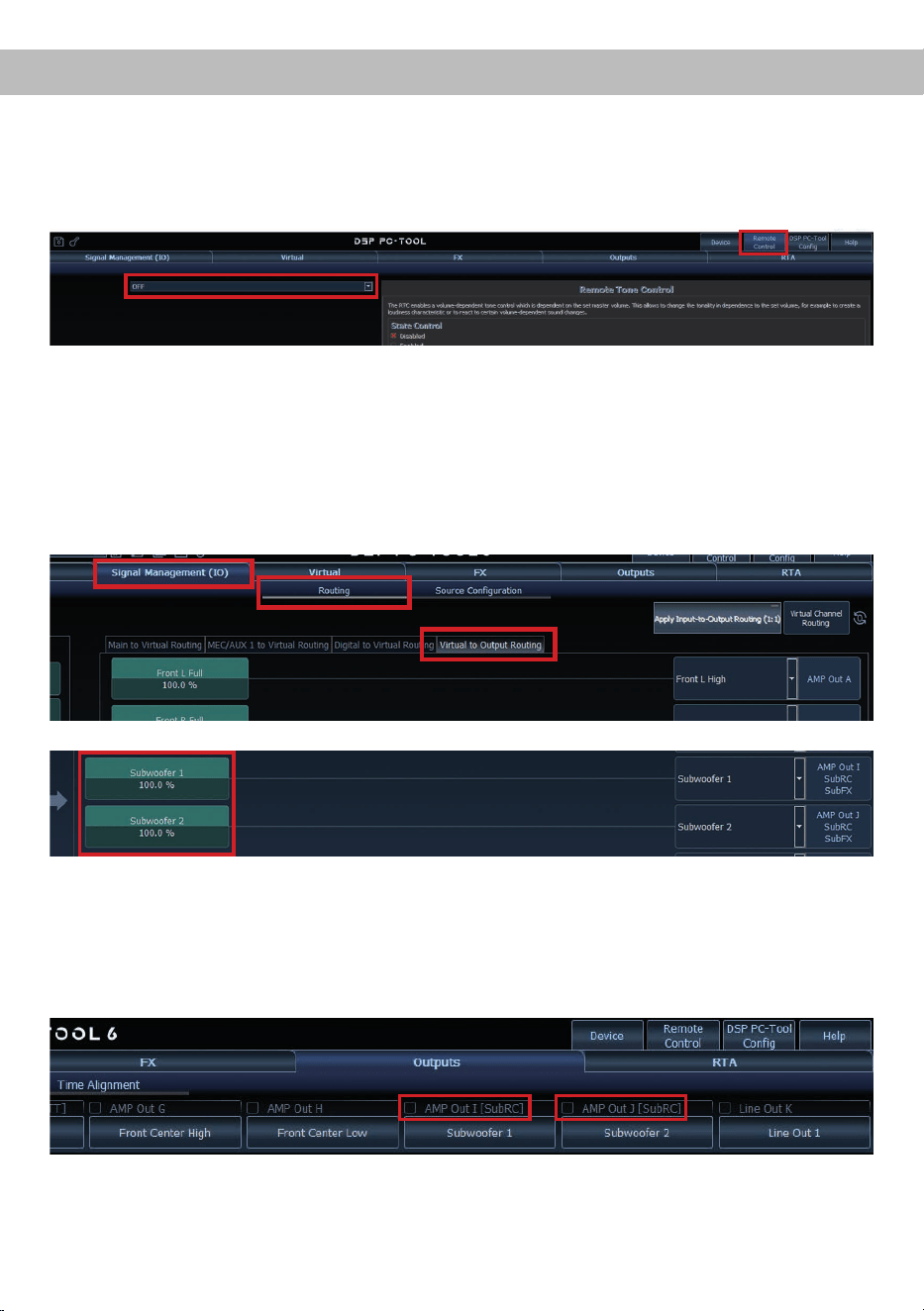
Konguration einer Subwoofer-Fernbedienung
Zur Konguration einer Subwoofer-Fernbedienung müssen im DSP PC-Tool bestimmte Einstellungen vor-
genommen werden.
Zunächst muss die entsprechende Fernbedienung im Tab „Remote Control“ aktiviert und je nach Modell
konguriert werden.
Die Subwoofer-Fernbedienung wirkt auf alle Ausgangskanäle, die im „Virtual to Output Routing“ mit einem
der beiden virtuellen Subwoofer-Signalen versorgt werden („Subwoofer 1“ oder „Subwoofer 2“). Dies kann
jede beliebige Kombination an Ausgangskanälen sein.
Im nachfolgenden Beispiel sind es die Verstärkerausgänge / AMP Outs I und J:
Hinweis: Bitte beachten Sie, dass den beiden virtuellen Subwoofer-Signalen „Subwoofer 1“ und / oder
„Subwoofer 2“ zuvor in den anderen Routing-Matrizen ein Eingangssignal zugewiesen werden muss.
Anschließend wird die Subwoofer-Regelung auch im „Outputs“ Menü hinter der Kanalbezeichnung als
[SubRC] angezeigt:

17
deACO Plattform-Features
Neben den einzigartigen DSP-Sound eekten bietet
die ACO-Plattform der UP 10DSP MK2 zusätzlich
eine Vielzahl an System-Features.
Im „Device“-Menü der DSP PC-Tool Software kön-
nen für einige dieser System-Features individuelle
Einstellungen vorgenommen werden.
ADEP.3 Conguration
Bei Ansteuerung des Verstärkers über die High-
level-Eingänge kann es in Verbindung mit manchen
Werksradios notwendig sein, den ADEP.3-Schalt-
kreis an den Diagnosemodus des Steuergeräts
anzupassen. Im Bereich „ADEP.3 SB compatibility
mode & Advanced Noise Suppression“ sollte eine
Anpassung vorgenommen werden, wenn es bspw.
zu Fehlfunktionen kommt (Stummschalten des
Radios). Standardmäßig ist der Kompatibilitätsmo-
dus eingeschaltet (Enabled).
URC Setup Switch Conguration
Der ACO bietet Speicherplatz für zehn anstelle der
üblichen zwei Sound Setups.
Mit Hilfe einer optional erhältlichen URC Fernbe
-
dienung oder des Control Tasters (Seite 3, Punkt 7)
lässt sich zwischen zwei der zehn Sound-Setup
Speicherplätze umschalten. Diese zwei Speicher
-
plätze können in der „URC Setup Switch Congurati-
on“ festgelegt werden. Werkseitig sind die Speicher-
bereiche eins und zwei ausgewählt.
Um zwischen
allen internen Speicherplätzen umschalten zu kön
-
nen, werden die optional erhältlichen Fernbedie-
nungen DIRECTOR und CONDUCTOR empfohlen.
Remote Output Conguration
An dieser Stelle kann festgelegt werden, ob der
Remote-Ausgang, der die angeschlossenen Ver-
stärker ein- bzw. ausschaltet, während eines
Sound-Setup-Wechselvorgangs kurzzeitig deakti-
viert werden soll. Standardmäßig ist dieses Feature
aktiviert (ON).
Turn On & O Delay
Hier kann die Verzögerungszeit, mit welcher der
Verstärker ein- und ausgeschaltet werden soll, fest-
gelegt werden. Werkseitig sind 0,2 Sekunden ein-
gestellt. Eine Änderung der Verzögerungszeit sollte
nur vorgenommen werden, wenn es beispielsweise
zu Störgeräuschen beim Ein- und Ausschalten des
Verstärkers kommt.
Power Save Mode
Diese Funktion ist standardmäßig aktiviert und
dient der Reduzierung der Leistungsaufnahme des
Verstärkers, wenn über einen bestimmten Zeitraum
kein Musiksignal erkannt wird.
Wird der Power Save Mode aktiv, schalten sich die
internen Verstärkerstufen sowie der Remote-Aus-
gang (REM OUT) automatisch ab. Liegt anschlie-
ßend wieder ein Musiksignal an, kehrt das Gerät
innerhalb von ca. 2 Sekunden in den Normalbetrieb
zurück.
Über die DSP PC-Tool Software kann die Funkti-
on ein- oder ausgeschaltet werden. Ist sie aktiviert,
lässt sich die Abschaltverzögerung im Bereich von
10 bis 600 Sekunden frei einstellen. Werkseitig be-
trägt die Verzögerungszeit 60 Sekunden.
18
Einbau einer Extension Card 2.0
Durch die Installation einer Extension Card 2.0
(EC 2.0) lässt sich der Verstärker um zusätzliche
Schnittstellen erweitern – z. B. für High-Denition
Bluetooth
®
Audio-Streaming, zusätzliche analoge
Eingänge und weitere Funktionen.
Zur Montage muss das Gerät geönet und die Ab-
deckblende des EC 2.0-Slots ausgetauscht werden.
Wichtig: Verwenden Sie ausschließlich für die-
ses Gerät freigegebene EC 2.0 Module und mon-
tieren Sie diese nur an der dafür vorgesehenen
Position. Falsche Module oder Einbauorte kön-
nen zu Schäden am Verstärker, der Extension
Card, dem Radio oder weiteren Komponenten
führen.
Im folgenden Abschnitt nun die wichtigsten Schritte
zum Einbau und der ersten Inbetriebnahme einer
Extension Card 2.0 (EC 2.0):
1. Verbindungen trennen
Trennen Sie alle Kabelverbindungen vom Gerät
.
2. Verstärker önen
Lösen Sie die drei Kreuzschlitzschrauben am
Seitenblech mit dem EC 2.0-Slot und entfernen
Sie dieses. Ziehen Sie anschließend das Bo-
denblech zur Seite heraus.
3. Seitenblech vorbereiten
Entfernen Sie die Abdeckblende der EC 2.0
vom zuvor demontierten Seitenblech, indem
Sie die zwei Inbusschrauben auf der Rückseite
lösen.
Montieren Sie nun die neue, der EC 2.0 beilie-
gende Abdeckblende. Achten Sie auf korrekte
Ausrichtung und ziehen Sie die Schrauben nur
handfest an.
4. EC 2.0 vorbereiten
Bereiten Sie das Modul gemäß dessen Bedie-
nungsanleitung für den Einbau vor.
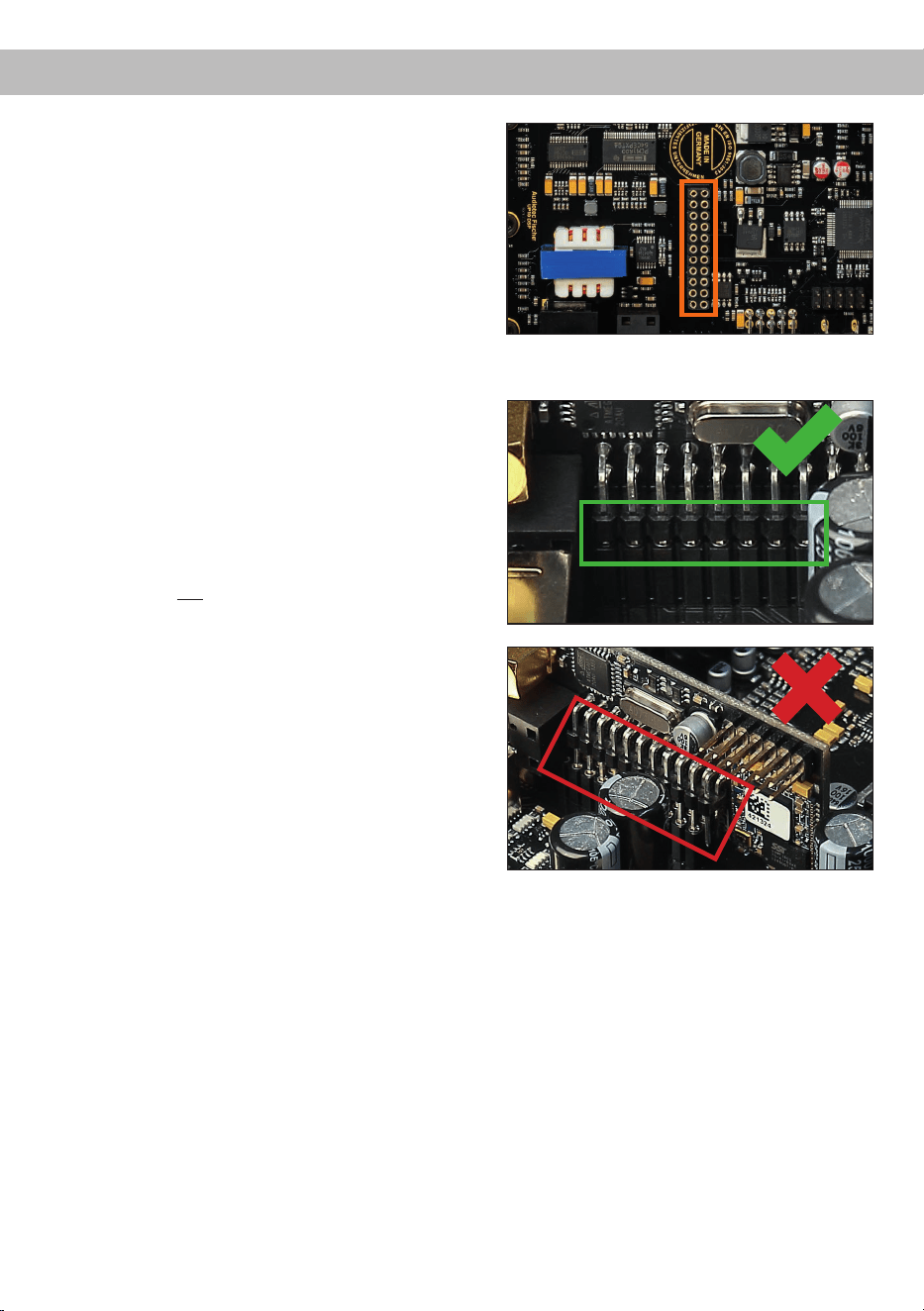
5. EC 2.0 in Verstärker einsetzen
Stecken Sie das Modul in den im Gerät vorge-
sehenen Sockel (siehe Markierung im nachfol-
genden Bild).
Achten Sie auf korrekten Sitz und vollständigen
Kontakt der Pins.
6. Verstärker wieder zusammensetzen
Schieben Sie das Bodenblech zurück ins Ge-
häuse und montieren Sie das Seitenblech mit
den drei Schrauben.
7. EC 2.0 xieren
Verschrauben Sie das Modul mit dem Seiten-
blech. Details nden Sie in der Anleitung der
jeweiligen EC 2.0.
8. Inbetriebnahme
Schließen Sie alle Kabel wieder an und schal-
ten Sie das Gerät ein. Die EC 2.0 wird auto-
matisch erkannt, die grüne Status-LED leuchtet
auf.
9. Konguration im DSP PC-Tool
Die EC 2.0 kann nun über die DSP PC-Tool
Software konguriert werden.

19
deTechnische Daten
Leistung RMS (≤ 1% THD+N)
- @ 4 Ohm ........................................................................ Kanal A - H: 65 Watt (min. 3 Ohm*)
Kanal I - J : 75 Watt (min. 3 Ohm*)
- @ 2 Ohm ........................................................................ Kanal I - J : 125 Watt
Max. Leistung pro Kanal** ................................................ Kanal A - H: bis zu 80 Watt RMS @ 4 Ohm
Kanal I - J : bis zu 90 Watt RMS @ 4 Ohm
Kanal I - J : bis zu 160 Watt RMS @ 2 Ohm
Verstärkertechnologie ....................................................... Class GD
Eingänge .......................................................................... 8 x Hochpegel-Lautsprechereingang
1 x Optisch SPDIF (12 - 96 kHz)
1 x Extension Card 2.0
Eingangsempndlichkeit ................................................... Kanal A - F: 4 - 16 Volt
Kanal G - H: 4 - 32 Volt
Eingangsimpedanz ........................................................... 9 - 33 Ohm mit ADEP.3
Ausgänge ......................................................................... 10 x Lautsprecherausgang
1 x Cinch
1 x Remote Out
Ausgangsspannung Cinch................................................3 Volt RMS
Frequenzbereich...............................................................15 Hz - 22.000 Hz
DSP Auösung .................................................................64 Bit
DSP Rechenleistung ........................................................295 MHz (1,2 Mrd. MAC Operationen/Sek.)
Abtastrate .........................................................................48 kHz
DSP Typ ...........................................................................Audio Signalprozessor
Signalwandler ................................................................... A/D: BurrBrown
D/A: BurrBrown
Signal- / Rauschabstand (A-bewertet) ............................. Digitaleingang: 105 dB
Analogeingang: 103 dB
Klirrfaktor (THD @ 1 kHz, 1 W an 4 Ohm) .......................< 0,015 %
Klirrfaktor (THD+N @ 1 kHz, 1 W an 4 Ohm) ...................< 0,02 %
Betriebsspannung.............................................................10,5 - 18 Volt (max. 5 Sek. bis hinab zu 6 Volt)
Leistungsaufnahme ..........................................................DC 12 V
60 A max.
Leerlaufstromaufnahme....................................................500 mA
Max. Remote-Ausgangsstrom .......................................... 500 mA
Betriebstemperaturbereich ...............................................-40 °C bis +70 °C
Sicherung .........................................................................2 x 25 A LP-Mini-Stecksicherung
Zusätzliche Features ........................................................ Class GD-Technologie mit dynamisch gere-
geltem Netzteil, 32 Bit CoProcessor, ADEP.3-
Schaltkreis, Start-Stop-Fähigkeit, Smart Control
Port, USB-C, Auto Remote-Schalter
Abmessungen (H x B x T) ................................................46 x 145 x 163 mm
* Gleichstromwiderstand min. 3,0 Ohm
** In typischen Mehrkanal-Anwendungen
20
Die Garantieleistung entspricht der gesetzlichen Regelung. Von der Garantieleistung ausgeschlossen sind
Defekte und Schäden, die durch Überlastung oder unsachgemäße Behandlung entstanden sind. Eine
Rücksendung kann nur nach vorheriger Absprache in der Originalverpackung, einer detaillierten Fehler-
beschreibung und einem gültigen Kaufbeleg erfolgen. Technische Änderungen, Druckfehler und Irrtümer
vorbehalten!
Für Schäden am Fahrzeug oder Gerätedefekte, hervorgerufen durch Bedienungsfehler des Gerätes, kön-
nen wir keine Haftung übernehmen.
Garantiehinweis
Dieses Symbol bedeutet, dass das Produkt nicht über den Hausmüll entsorgt werden darf,
sondern bei einer entsprechenden Sammelstelle zum Recycling abgegeben werden muss.
Befolgen Sie die örtlichen Vorschriften und entsorgen Sie das Produkt niemals mit dem nor-
malen Hausmüll. Die ordnungsgemäße Entsorgung von Altgeräten trägt zur Vermeidung von
Umwelt- und Gesundheitsschäden bei.
Hinweise zur Entsorgung
Markenzeichen
Dieses Produkt ist mit einer CE-Kennzeichnung versehen. Damit ist das Gerät für den Betrieb
in Fahrzeugen innerhalb der Europäischen Union (EU) zertiziert.
Dieses Produkt ist mit einer UKCA-Kennzeichnung versehen. Damit ist das Gerät für den
Betrieb in Fahrzeugen innerhalb des Vereinigten Königreichs zertiziert.
Dieses Produkt ist mit einer EAC-Kennzeichnung versehen. Damit ist das Gerät für den Betrieb
in Fahrzeugen innerhalb der Eurasian Customs Union zertiziert.
Regulatorische Hinweise
Die Bluetooth
®
Wortmarke und die Logos sind eingetragene Warenzeichen der Bluetooth SIG, Inc. und
jegliche Nutzung dieser Marken durch die Audiotec Fischer GmbH geschieht unter Lizenz. Andere Han
-
delsmarken und Handelsnamen gehören den jeweiligen Inhabern.

21
Dear Customer,
Congratulations on your purchase of this innovative
and high-qual ity MATCH product.
With more than 35 years of experience in research
and development of audio products this amplier
sets new standards in digital amplier technology.
It was developed using state-of-the-art engineering,
which is reected in its excellent build quality and
the use of sophisticated technologies.
We wish you many hours of enjoyment with your
new MATCH UP 10DSP MK2 .
Yours,
AUDIOTEC FISCHER
General installation instructions for MATCH
components
To prevent damage to the unit and possible injury,
read this manual carefully and follow all installation
instructions. This product has been checked for
proper function prior to shipping and is guaranteed
against manufacturing defects.
Before starting your installation, disconnect the
battery’s negative terminal to prevent damage
to the unit, re and / or risk of injury. For a prop-
er performance and to ensure full warranty cover-
age, we strongly recommend having this product
installed by an authorized MATCH dealer.
Install your UP 10DSP MK2 in a dry location with
sucient air circulation for proper cooling of the
equipment.
For safety reasons, the amplier must be profes-
sionally installed. Therefore, use the two mounting
plates which are included. These are attached to
the bottom of the amplier with two short screws
which are included in delivery, too.
When screwing the amplier to the vehicle chassis,
carefully examine the area around and behind the
proposed installation location to ensure that there
are no electrical cables or components, hydraulic
brake lines or any part of the fuel tank located be-
hind the mounting surface. Failure to do so may re-
sult in unpredictable damage to these components
and possible costly repairs to the vehicle.
General instructions for connecting the MATCH
UP 10DSP MK2 amplier
The amplier may only be installed in motor vehi-
cles which have a 12 Volts negative terminal con-
nected to the chassis ground. Any other system
could cause damage to the amplier and the electri-
cal system of the vehicle.
The positive cable from the battery for the entire
sound system should be provided with a main fuse
at a distance of max. 30 cm from the battery. The
value of the fuse is calculated from the maximum
total current draw of the car audio system and the
cable cross section used.
Use only the included MATCH cable or an op-
tionally available MATCH cable harness for
connection of the UP 10DSP MK2. The use of
other cables can result in damage of the ampli-
er, the head unit / car radio or the connected
loudspeakers! The fuses of the amplier may
only be replaced by identically rated fuses
(2 x 25 A) to avoid damage of the amplier.
Prior to installation, plan the cable routing to avoid
any possible damage to the wiring harness. All
cabling should be protected against pinching or
crushing hazards. Also avoid routing cables close
to potential noise sources such as electric mo-
tors, high-power accessories and other vehicle
harnesses.
Congratulations!
General instructions
en
22
Connectors and control units
1
Speaker Output E - J
Page 26, point 4
2
Highlevel Input E - H
Page 26, point 3
3
System Connector input
Page 26, point 2
4
Remote connectors
Page 27, point 7
5
Power connector
Page 27, point 8
6
USB-C input
Page 28, point 9
7
Control pushbutton
Page 31, point 2
8
SCP (Smart Control Port)
Page 31, point 3
9
Extension Card 2.0 Slot
Page 37
10
Optical Input
Page 26, point 5
11
Line Output
Page 29, point 13
12
Auto Remote switch
Page 27, point 6
13
Status LED
Page 31, point 1
1 2 3 4 5
6 7 8 9 10 11
13
12
23
enHardware conguration
Fig. 1: Pin conguration UP 10DSP MK2
* Not used on the enclosed System Connector connection cable.
System Connector
1. Highlevel loudspeaker input rear left (-) / C
2. Highlevel loudspeaker input front left (-) / A
3. Highlevel loudspeaker input front right (-) / B
4. Highlevel loudspeaker input rear right (-) / D
5. Loudspeaker output rear right (-) / D
6. Loudspeaker output rear left (-) / C
7. Loudspeaker output front right (-) / B
8. Loudspeaker output front left (-) / A
9. Ground* / Warning: Do not use this pin!
10. Ground* / Warning: Do not use this pin!
11. Highlevel loudspeaker input rear left (+) / C
12. Highlevel loudspeaker input front left (+) / A
13. Highlevel loudspeaker input front right (+) / B
14. Highlevel loudspeaker input rear right (+) / D
15. Loudspeaker output rear right (+) / D
16. Loudspeaker output rear left (+) / C
17. Loudspeaker output front right (+) / B
18. Loudspeaker output front left (+) / A
19. Warning: Do not use this pin!*
20. Warning: Do not use this pin!*
Highlevel Input E - H
21. Highlevel loudspeaker input channel H (-)
22. Highlevel loudspeaker input channel G (-)
23. Highlevel loudspeaker input channel F (-)
24. Highlevel loudspeaker input channel E (-)
25. Highlevel loudspeaker input channel H (+)
26. Highlevel loudspeaker input channel G (+)
27. Highlevel loudspeaker input channel F (+)
28. Highlevel loudspeaker input channel E (+)
HIGHLEVEL
INPUT
POWER INPUT
SPEAKER
OUTPUT
+12V GNDIN
REM
OUT
SYSTEM
CONNECTOR
403938373635 28272625 20191817161514131211
343332313029 24232221 10987654321
Speaker Output E - J
29. Subwoofer output 2 (-) / J
30. Subwoofer output 1 (-) / I
31. Loudspeaker output H (-)
32. Loudspeaker output G (-)
33. Loudspeaker output F (-)
34. Loudspeaker output E (-)
35. Subwoofer output 2 (+) / J
36. Subwoofer output 1 (+) / I
37. Loudspeaker output H (+)
38. Loudspeaker output G (+)
39. Loudspeaker output F (+)
40. Loudspeaker output E (+)
24
Hardware conguration
Fig. 2: Overview connection cables
1
System Connector connection cable
2
Speaker Output E - J connection cable
3
Highlevel Input E - H connection cable
4
Remote (REM IN / OUT) connection cable
1 2 3
Fig. 3: Pin assignment Power Input plug
Plug top side
A
+12 V – for connecting the UP 10DSP MK2 to the
positive terminal of the car´s battery
B
GND – for connecting the ground cable.
4
A
B
25
en
Congure the MATCH UP 10DSP MK2 as follows
Caution: Carrying out the following steps will re-
quire special tools and technical knowledge. In or-
der to avoid connection mistakes and / or damage,
ask your dealer for assistance if you have any ques-
tions and follow all instructions in this manual (see
page 21). It is recommended that this unit will be
installed by an authorized MATCH dealer.
1. Adjusting input voltage range of the high-
level speaker inputs G & H
The UP 10DSP MK2 is equipped with two
high-power highlevel speaker inputs with up to
32 V input sensitivity. These are channels G &
H. Before you start adjusting the input voltage
range ("Voltage Range") of the signal inputs,
please note the following information. This ad-
justment is only necessary when connecting
devices from the following categories:
- Factory-installed sound system ampliers
with up to two high power outputs with an
output power of more than 50 W RMS
For standard applications, such as connecting:
- Factory radios
- Factory-installed sound system ampliers
with less than 50 W RMS output power
this adjustment is not required. In such cases,
you can proceed directly to point 2 on page 26.
Example settings for the input sensitivity can be
found on page 30.
To set the input voltage range, follow these
steps:
a. Open the amplier
Remove the side panel with the USB-C input
by loosening the three Phillips screws. After-
wards slide out the bottom panel to the side.
b. Determine the output voltage of the signal
source
We recommend measuring the maximum
output voltage using an appropriate mea-
suring device or contacting your authorized
MATCH dealer. If you are unsure, we recom-
mend setting the jumper to the „High Voltage
Range“ (Input G - H 32 V) to avoid potential
damage to the device. To do this, the jumper
must be moved to the factory-unused multi-
pin connector, as shown in gure 2.
c. Place the jumper in the corresponding
voltage range
To change the jumper´s position, simply lift
it upwards and insert it into the desired posi-
tion. Ensure that the jumper is fully inserted
and not oset.
Overview jumper plug-in positions:
Low voltage range conguration
( by default / see g. 1):
Value range: 4 - 16 Volts
High voltage range conguration
(see g.2):
Value range: 8 - 32 Volts
Figure 1:
Figure 2:
d. Reassemble the amplier

26
2. Connecting the System Connector
1.
Connecting the highlevel speaker inputs A - D:
The highlevel loudspeaker inputs (see
page 23, g. 1, no. 1 - 4 and 11 - 14) can
be connected directly to the loudspeaker out-
puts of an OEM radio or aftermarket radio by
using the enclosed MATCH connection ca-
ble. It is not necessary to use all highlevel
speaker inputs. It is sucient if two of four
highlevel loudspeaker inputs are connected.
With the DSP PC-Tool software it is possi-
ble to route the input signals to the 11 output
channels individually. Make sure that the po-
larity is correct. If one or more connections
have reversed polarity it may aect the per-
formance of the amplier. If this input is used
the remote input (REM IN) does not need to
be connected as the amplier will automat-
ically turn on once a loudspeaker signal is
received.
2. Connecting the loudspeaker outputs A - D:
The loudspeaker outputs (see page 23,
g. 1, no. 5 - 8 and 15 - 18) can be connect-
ed directly to the wires of the loudspeakers
by using the enclosed MATCH connection
cable.
Never connect any of the loudspeaker cables
to the chassis ground as this will damage
your amplier and your speakers. Ensure
that the loudspeakers are correctly connect-
ed (phase), i.e. plus to plus and minus to
minus. Exchanging plus and minus causes
a total loss of bass reproduction. The plus
pole is indicated on most speakers. The im-
pedance per channel must not be lower than
3 Ohms*, otherwise the amplier protection
will be activated.
Attention: Solely use the System Connector
connection cable (see page 24, g. 2) which
is included in delivery or an appropriate ca-
ble harness from the MATCH accessories
program for connection!
3. Optional: Connecting the highlevel speaker
inputs E - H
The highlevel loudspeaker inputs E - H can be
connected directly to the loudspeaker outputs
of an OEM radio or aftermarket radio using
the enclosed MATCH connection cable (see
page 23, g. 1, no. 21 - 28). Make sure that the
polarity is correct. If one or more connections
have reversed polarity it may aect the perfor-
mance of the amplier. Channels G & H can
also be connected to more powerful factory-in-
stalled sound system ampliers, provided that
the input voltage range has been adjusted in
advance according to point 1 on page 25.
If this input is used the remote input (REM IN /
page 22, point 4) does not need to be connect-
ed as the amplier will automatically turn on
once a loudspeaker signal is received.
Attention: Solely use the connection cable
with the 8-pole connector and ying leads (see
page 24, g. 2) which is included in delivery or
an appropriate cable harness from the MATCH
accessories program!
4.
Optional: Connecting the speaker outputs E - J
The loudspeaker outputs allow to connect
speaker systems using the included connection
cable as well as subwoofers to the two power
channels I & J (see page 23, g. 1, no. 29 - 40).
Never connect any of the loudspeaker cables
with the chassis ground as this will damage
your amplier and your speakers. Ensure that
the loudspeakers are correctly connected (in
phase), i.e. plus to plus and minus to minus.
Exchanging plus and minus causes a total loss
of bass reproduction. The plus pole is indicated
on most speakers. The impedance of channels
E - H must not be lower than 3 Ohms*, and for
channels I and J not lower than 2 Ohms. Oth-
erwise, the amplier’s protection circuit will be
activated.
Attention: Solely use the connection cable with
the 12-pole connector and ying leads (see
page 24, g. 2) which is included in delivery for
connecting further loudspeakers or an appropri-
ate cable harness from the MATCH accessories
program!
5. Connecting a digital signal source
If you have a signal source with a digital op-
tical output you can connect it to the amplier
using the appropriate input (Optical Input). The
sampling rate must be between 12 and 96 kHz.
The input signal is automatically adapted to the
internal sample rate.
Hardware conguration
*DC resistance min. 3.0 Ohms

27
en
By default, manual activation via an optional re-
mote control is enabled.
Alternatively you can activate the automatic
turn-on feature in the DSP PC-Tool software
under the “Signal Management (IO)” tab in the
“Source Conguration” sub-menu.
The automatic turn-on circuit does not work
when the digital input is used. Therefore it is
mandatory to connect the remote input (REM
IN / page 22, point 4).
Important: Digital audio signals typically do not
contain volume level information. Keep in mind
that this will lead to full level on the outputs of
the UP 10DSP MK2 and your connected ampli-
ers. This may cause severe damage to your
speakers. We strongly recommend using an
optional remote control for adjusting the volume
level of the digital signal input!
Note: The MATCH UP 10DSP MK2 can only
handle uncompressed digital stereo signals in
PCM format with a sample rate between 12 kHz
and 96 kHz.
6. Conguration of the remote input
The UP 10DSP MK2 will be turned on automat-
ically if the highlevel inputs of the System Con-
nector and / or the Highlevel Inputs E - H are
used or if a signal is applied to the remote input
terminal. The Auto Remote switch (see page
22, point 12) allows you to deactivate the au-
tomatic turn-on feature of the highlevel inputs.
The feature should be deactivated if there are
e.g. noises while switching on / o the amplier.
On: Activation via highlevel speaker input is
enabled (by default).
O: Activation via highlevel speaker input is
disabled.
Note: If the automatic turn-on function is deac-
tivated it is mandatory to use the remote input
terminal to power up the amplier! The highlevel
signal will be ignored in this case.
7. Connecting the remote connectors
Only connect the remote wires using the 2-pole
connection cable with the ying leads which is
included in delivery (see page 24, g. 2) or an
appropriate cable harness from the MATCH
accessories program.
REM IN: The remote input is used to switch the
amplier on and o if the signal source connect-
ed to the System Connector or Highlevel Input
E - H does not activate the automatic turn-on
function, if the digital input is used, or if the am
-
plier should deliberately be controlled only via a
remote signal. To do this, connect the amplier´s
remote input to the remote output / automatic
antenna (aerial positive) output of the head unit /
car radio. Thus the amplier is switched on and
o together with the head unit.
We do not recommend controlling the remote
input via the ignition switch to avoid pop noise
during turn on / o.
Note: This input does not need to be assigned
if one of the highlevel inputs A - H is used. To
deactivate the “automatic turn-on” function read
the description in point 6 “Conguration of the
remote input”.
REM OUT:
The remote output is used for turn-
ing on / o an amplier that is connected to the
pre-amplier output (Line Out) of the MATCH
UP 10DSP MK2 . Therefore connect the remote
output of the UP 10DSP MK2 to the remote in-
put of your amplier to switch it on and o via
the internal DSP without interfering signals.
The remote output is activated automatically
as soon as the booting process of the DSP
is completed. Additionally this output will be
turned o during the “Power Save Mode” or a
software update process.
Important: Never use a dierent signal than
the remote output of the UP 10DSP MK2 to
activate a connected amplier!
8. Connection to power supply
ATTENTION:
Make sure to disconnect
the battery before installing the MATCH
UP 10DSP MK2!
Solely use the Power Input plug which is in-
cluded in delivery for connection (see page 24,
g. 3). Make sure of correct polarity.
+12 V: Connect the +12 V power cable to the
positive terminal of the battery. The positive
wire from the battery to the ampliers power ter-
minal needs to have an inline fuse at a distance
of no more than 12 inches (30 cm) from the
battery. The value of the fuse is calculated from
the maximum total current input of the whole
car audio system and the cable cross section
28
used (UP 10DSP MK2 = max. 60 A at 12 V pow-
er supply). If your power wires are short (less
than 1 m / 40”) then a wire gauge of 6 mm² /
AWG 10 will be sucient. In all other cases we
strongly recommend gauges of 6 - 10 mm² /
AWG 10 – 8!
GND: Connection for the ground cable. The
ground cable must be connected to a non-in-
sulated point on the vehicle chassis. The cable
cross section should be the same size as the
+12 V cable. Inadequate grounding causes au-
dible interference and malfunctions.
9. Connecting the PC & rst start-up
The USB-C input (see page 22, point 6) en-
ables the connection of the amplier to a
personal computer and its free conguration
with our DSP PC-Tool software using the pro-
vided USB-C cable. Before you connect the
UP 10DSP MK2 to a computer for the rst time,
download the latest DSP PC-Tool software (at
least version 6) from our homepage. The soft-
ware and a comprehensive knowledge base
can be found at www.audiotec-scher.com.
It is advisable to check regularly for software
updates so that the device is always up to date.
We strongly recommend to carefully read the
DSP PC-Tool knowledge base before using the
software for the rst time in order to avoid any
complications and failures.
Important: Make sure that the amplier is not
connected to your computer before the soft-
ware and USB driver are installed!
In the following the most important steps how
to connect and the rst start-up are described:
1. Download the latest version of the DSP
PC-Tool software (available on our website
www.audiotec-scher.com) and install it
on your computer.
2. Connect the amplier to your computer us-
ing the USB-C cable that is included in de-
livery. If you have to bridge longer distances
please use an active USB extension cable
with integrated repeater.
3. First turn on the UP 10DSP MK2 and then
start the software. If required, the amplier´s
rmware will be updated automatically.
10. Adjustment of the input sensitivity of the an-
alog inputs
ATTENTION: It is mandatory to properly adapt
the input sensitivity of the UP 10DSP MK2 to
the signal source to achieve the best possible
signal quality and avoid damage to the amplier.
It is also mandatory to adjust the “Voltage
Range” of the signal inputs G & H to the out-
put voltage of your signal source (see page 25,
point 1).
The input sensitivity of each channel pair must
be optimally adjusted to the signal source using
the DSP PC-Tool software.
The input sensitivity is factory-set to 11 Volts
for all channels. This value serves as the opti-
mal basic setting and must be adjusted as de-
scribed below.
Note: Mute all signal outputs of the
UP 10DSP MK2 during this setup.
1. Connect the amplier to a computer and start
the DSP PC-Tool software (see point 8 on
the left). Then mute all signal outputs of the
amplier in the software. The function can
be found in the “Input” tab in the sub-menu
“Gain Conguration”.
2. Select the setup method to adjust the input
sensitivity.
Standard Gain Setup: This method allows for
global adjustment of input sensitivity for all
input channels.
Advanced Gain Setup: This method allows
individual conguration of each channel pair.
Hardware conguration
29
en
3. Set the volume of your head unit to approx-
imately 90 % of the maximum volume and
play the specially developed "IGS - Input
Gain Setup" signal. You can nd this signal in
the DSP PC-Tool under "Audio Test Tracks"
(home screen →
).
4. Normally, the clipping indicator in the DSP
PC-Tool is o (gray) and only lights up if one
of the analog inputs is overdriven.
Now increase the input sensitivity using the
scroll bar until the clipping indicator lights up
red (see the following picture).
5. Then turn the control back one step until the
clipping indicator turns o again. If the clip-
ping LED lights up red continuously even at
11 Volts, the input signal level is too high. To
prevent damage, please contact an autho-
rized MATCH dealer.
6. Standard Gain Setup: The process is now
complete.
Advanced Gain Setup: Repeat this process
for each input channel pair used.
11. Conguration of the internal DSP
IMPORTANT: The general amplier settings
should be congured with the DSP PC-Tool
software before initial start-up to prevent dam-
age to the sound system and the connected
speakers. After connecting the device to a PC,
the amplier can be congured in the DSP
PC-Tool. Useful information for proper cong-
uration can be found in our knowledge base at
www.audiotec-scher.com.
Caution: We highly recommend setting the
volume of your car radio to the minimum posi-
tion and to mute all signal outputs. Especially if
the UP 10DSP MK2 will be used in fully active
applications, a wrong setup can destroy your
speakers right away.
12. Optional: Analyzing the input signal
When using highlevel signals, we recommend
analyzing the input signal with the Advanced
Input Signal Analyzer (AISA) in the DSP PC-
Tool. This helps detect and correct factory-set
equalization, time alignment, or allpass lters if
present. Information on the AISA can be found
in the extensive Knowledge Base on our web-
site www.audiotec-scher.com.
13.
Optional: Connecting the pre-amplier output
The Line Out (see page 22, point 11) is a mono
low level output for connecting an additional
power amplier. This output can be connected
to the RCA / Cinch input of the external amplier
using an appropriate RCA / Cinch cable. The
output provides a maximum output voltage of
3 Volts RMS.
When using this output, it is essential to switch
the external amplier on and o via the remote
output (REM OUT / see page 22, point 4) of the
UP 10DSP MK2 to avoid unwanted noise.
14. Sound tuning
Now you can create your sound setup.
Information about sound tuning can be
found in our extensive knowledge base at
www.audiotec-scher.com or contact your
local MATCH dealer.
30
Figure 1:
Voltage range 4 - 16 Volts
Figure 2:
Voltage range 8 - 32 Volts
For further applications please contact your MATCH specialist dealer.
J 2
J 1
Hardware conguration
Examples for adjusting the input sensitivity of the channels G & H:
Source Jumper position
Input Gain in DSP PC-Tool
OEM-Radio
Up to 25 Watts RMS power per
channel at 4 Ohms or up to 50 Watts
RMS power at 2 Ohms
Low voltage range (J 1) –
Ex factory jumper position
(see g. 1)
OEM-Radio with additional
amplier
>25 Watts and up to 200 Watts RMS
power at 4 Ohms or up to 100 Watts
RMS power per channel at 8 Ohms
High voltage range (J 2)
(see g. 2)
31
enAdditional functions
1. Status LED
The Status LED (see page 22, point 13) indi-
cates the operating mode of the amplier and
its DSP memory.
Green: Amplier is ready for operation.
Orange: Power Save Mode is activated.
Red: Protection Mode is active. This may have
dierent root causes. The amplier is equipped
with protection circuits against over- and under-
voltage as well as overheating. Please check
for connecting failures such as short-circuits
or other wrong connections. If the amplier is
overheated the internal temperature protection
switches o the remote and signal output until it
reaches a safe temperature level again.
Red / green slow ashing: No operating soft-
ware installed. Connect the amplier to the DSP
PC-Tool software and conrm the automatic up-
date of the operating system. You will nd the
latest version of the DSP PC-Tool software at
www.audiotec-scher.com.
Red / green fast ashing: The currently selected
sound setup memory is empty. A new setup has
to be loaded via the DSP PC-Tool software or
switch to a memory position with existing sound
setup.
2. Control pushbutton
The UP 10DSP MK2 provides 10 internal mem-
ory locations for sound setups. The Control
pushbutton (see page 22, point 7) allows the
user to switch between two memory positions.
These can be dened in the DSP PC-Tool. In
addition a device reset can be made by press-
ing the button for a longer period.
1. Setup switch: Press Control pushbutton for
1 second. The memory locations one and two
are dened by default. Switching is indicated
by a single red ash of the Status LED. Alter-
natively, the optional URC.3 remote control can
be used for switching. To switch between all in-
ternal memory locations, optional accessories
like the DIRECTOR display remote control or
CONDUCTOR are required.
2. Device reset: Press pushbutton for ve sec-
onds. This completely erases the internal mem-
ory and is indicated by a continuous red glowing
and constant green ashing of the Status LED.
Attention: After erasing the setups from mem-
ory the UP 10DSP MK2 will not reproduce any
audio output until the device is updated via the
DSP PC-Tool software.
3. SCP (Smart Control Port)
This multi-functional input (see page 22, point 8)
is designed for MATCH UP 10DSP MK2 acces-
sory products like a remote control which allows
to adjust several features of the amplier. De-
pending on the type of remote control, at rst
its functionality has to be dened in the “ Device
Conguration Menu” of the DSP PC-Tool soft-
ware.
Attention: If the accessory product does not
have a SCP connector, a SCP-to-Control Input
adaptor (Art-Nr. M141313) is optionally avail-
able from your specialist dealer.
SCP-to-Control Input adaptor

32
A basic DSP setup can be found at www.audiotec-scher.com under Tools → Sound Setups.
For further applications please contact your MATCH specialist dealer.
Conguration examples
Example 1: Channel routing with Virtual Channel Processing
Inputs Outputs To speakersVirtual channels
4-channel head unit > Front: 3-way fully active; Rear: 2-way fully active + Line Out for external subwoofer
Example 2: 10-channel 1 to 1 channel routing (IOR) e.g.: Front 2-way fully active / Rear 2-way pas-
sive / Center 2-way fully active / Subwoofer with dual voice coil – only in combination with the
optional Extension Card 2.0 – ANALOG IN
From car radio
Subwoofer
1
(K)
SFX -
Augmented Bass
Processing
Front L High – tweeter FL
Front R High – tweeter FR
Front L Mid – midrange FL
Front R Mid – midrange FR
Front L Low – mid-woofer FL
Front R Low – mid-woofer FR
Rear L High – tweeter RL
Rear R High – tweeter RR
Rear L Low – mid-woofer RL
Rear R Low – mid-woofer RR
Subwoofer 1 – subwoofer
Front L Full
Front R Full
Rear L Full
Rear R Full
Amp Out A
Amp Out C
Amp Out I
Amp Out B
Amp Out D
Amp Out J
Amp Out E
Amp Out G
Amp Out F
Amp Out H
Line Out K
Input A
Input B
Input C
Front L Full (A)
Front R Full (B)
Rear L Full (C)
Rear R Full (D)
Input D
Sum signal
A to D
SFX -
Front Processing
SFX -
Front Processing
From factory
amplier
Front L High
Front R High
Front L Low
Front R Low
Rear L Full
Rear R Full
Subwoofer L
Subwoofer R
Front Center High
Front Center Low
Front L High – tweeter FL
Front R High – tweeter FR
Front L Low – mid-woofer FL
Front R Low – mid-woofer FR
Rear L Full – 2-way passive
Rear R Full – 2-way passive
Front Center High –
tweeter center
Front Center Low –
midrange center
Subwoofer 1 – subwoofer L
Subwoofer 2 – subwoofer R
Input A
Input B
Input C
Input D
Input E
Input F
Input G*
Input H*
Input I
Input J
Amp Out A
Amp Out B
Amp Out C
Amp Out D
Amp Out E
Amp Out F
Amp Out G
Amp Out H
Amp Out I*
Amp Out J*
* The high power signal inputs G & H (see page 25, point 1) are
routed to the high power subwoofer channels I & J.
Inputs Outputs To speakersVirtual channels
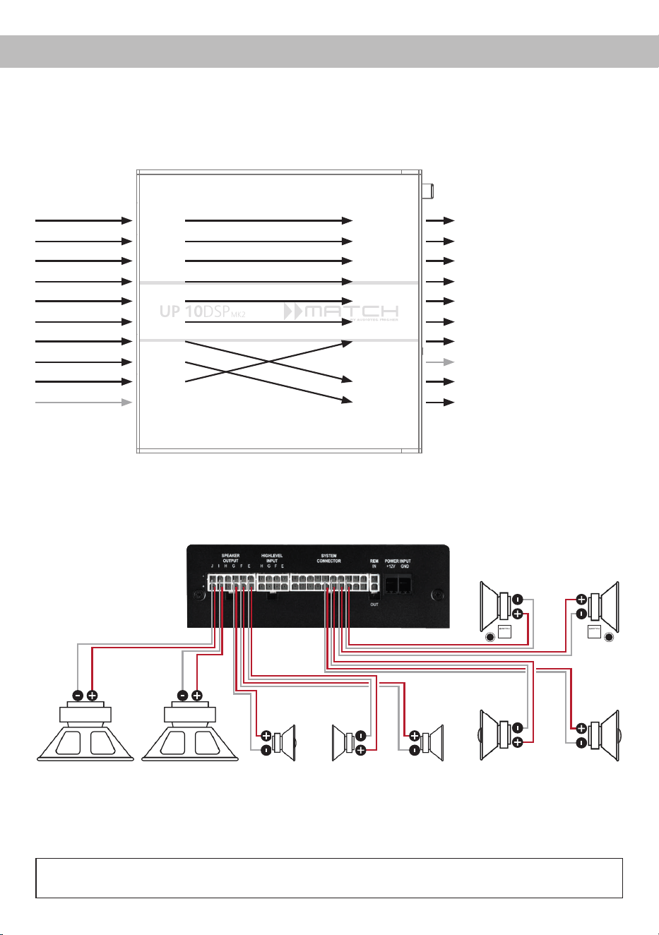
33
en
*DC resistance min. 3.0 Ohms
Example 3: 9-channel 1 to 1 channel routing (IOR) e.g. Mercedes Burmester or BMW Harman Kardon
with the optional MATCH UPGRADE harnesses – only in combination with the optional Extension
Card 2.0 – ANALOG IN
From factory
amplier
Inputs Outputs To speakers
Front L Full
Front R Full
Rear L Full
Rear R Full
Surround L Full
Surround R Full
Subwoofer L
Subwoofer R
Front Center Full
Not assigned
Front L Full – 2-way passive FL
Front R Full – 2-way passive FR
Rear L Full – 2-way passive RL
Rear R Full – 2-way passive RR
Surround L Full – fullrange L
Surround R Full – fullrange R
Front Center Full – coaxial center
Not assigned
Subwoofer 1 – subwoofer L
Subwoofer 2 – subwoofer R
Input A
Input B
Input C
Input D
Input E
Input F
Input G*
Input H*
Input I
Input J
Amp Out A
Amp Out B
Amp Out C
Amp Out D
Amp Out E
Amp Out F
Amp Out G
Amp Out H
Amp Out I*
Amp Out J*
* The high power signal inputs G & H (see page 25, point 1) are
routed to the high power subwoofer channels I & J.
Subwoofer R
Left Right
Passive system front
(min. 3 Ohms*)
Left Right
Coaxial speakers rear
(min. 3 Ohms*)
Subwoofer L Center
(min. 3
Ohms*)
Left Right
Surround
(min. 3 Ohms*)
Alternative: One subwoofer with 2 x 2 Ohms
dual voice coil
A basic DSP setup can be found at www.audiotec-scher.com under Tools → Sound Setups.
For further applications please contact your MATCH specialist dealer.
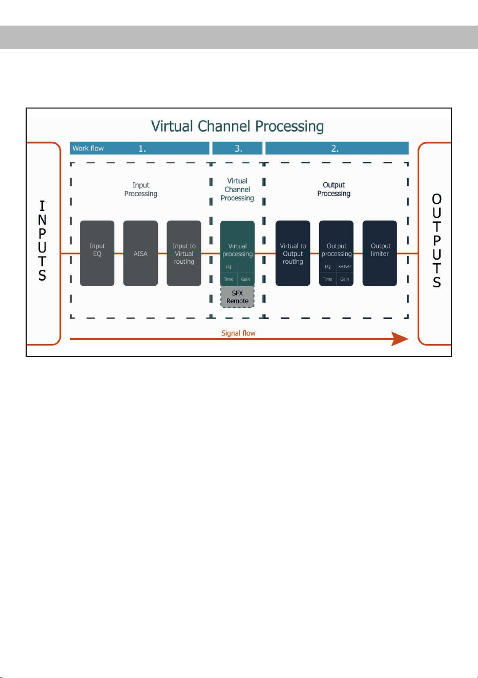
34
Virtual Channel Processing (VCP)
The VCP extends the scope of the device by an additional layer of processed channels, which is located
between the inputs and outputs. A total of eight additional processed virtual channels and 11 processed
output channels are available.
This virtual channel layer oers several advantages, especially in complex system congurations.
The main advantages of this concept are:
- Cross-channel group equalizers that aect several output channels simultaneously
- Multi-way speaker conguration of DSP sound eects (SFX)
- Additional features such as Rear Attenuation
For further information on the VCP and its conguration, please refer to our Knowledge Base at
www.audiotec-scher.com.
The MATCH UP 10DSP MK2 oers Virtual Channel Processing (VCP), a multi-stage signal processing
concept that enables the perfect conguration of complex sound systems, opening up completely new
possibilities for sound tuning.
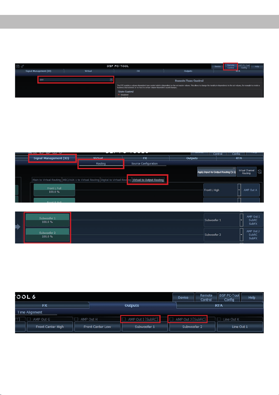
35
enConguration of a subwoofer remote control
In order to congure a subwoofer remote control, specic settings have to be made in the DSP PC-Tool.
First, the appropriate remote control must be activated in the “Remote Control” tab and then congured,
depending on the model.
The subwoofer remote control is tied to the output channels that are supplied with one of the two virtual
subwoofer signals (“Subwoofer 1” or “Subwoofer 2”) in the “Virtual to Output Routing” matrix. This can be
any combination of output channels.
In the following example, these are the amplier outputs I and J:
Note: Please note that an input signal must be assigned to the two virtual subwoofer signals “Subwoofer 1”
and / or “Subwoofer 2” in the other routing matrices.
The subwoofer control is then also displayed in the “Outputs” menu next to the name of the channel as
[SubRC]:

36
ACO platform features
In addition to its unique DSP sound eects, the
UP 10DSP MK2 provides a bunch of system and
DSP features.
In the “Device” menu of the DSP PC-Tool software
individual settings can be made for several of these
system features.
ADEP.3 Conguration
If the UP 10DSP MK2 is connected to an OEM ra-
dio via the highlevel inputs it may happen that the
ADEP.3 circuit has to be adapted to the diagnostic
mode of the radio if the latter is equipped with a so-
called “class SB” output stage.
In the “ADEP.3 SB compatibility mode & Advanced
Noise Suppression” section, an adjustment should
be made if distortions occur in the upper volume
range, for example.
The compatibility mode is enabled by default.
URC Setup Switch Conguration
The ACO provides ten internal memory locations for
sound setups instead of the common two.
By using an optional URC remote control or the Con
-
trol pushbutton (see page 22, point 7) it is possible
to toggle between two of the ten memory locations.
These two memory locations can be determined in
the “URC Setup Switch Conguration”. The memory
locations one and two are preassigned by default.
To switch between all internal memory locations, the
optionally available remote controls DIRECTOR and
CONDUCTOR are recommended.
Remote Output Conguration
This function controls if the remote output (which
switches on and o the connected ampliers) will
be temporarily deactivated during a sound setup
switch. This function is activated (ON) by default.
Turn On & O Delay
This function allows to determine the delay time
with which the integrated DSP is switched on and
o. The factory setting is 0.2 seconds. The delay
time should only be modied if there are e.g. noises
while switching on / o the amplier.
Power Save Mode
This function is activated by default and is used to
reduce the power consumption of the amplier if no
music signal is detected for a certain period of time.
When Power Save Mode is active, the internal am-
plier stages and the remote output (REM OUT) are
automatically switched o. Once a music signal is
detected again, the device returns to normal opera-
tion within approximately 2 seconds.
The function can be switched on or o using the
DSP PC-Tool software. If it is activated, the switch-
o delay can be freely set in the range from 10 to
600 seconds. The default delay time is 60 seconds.
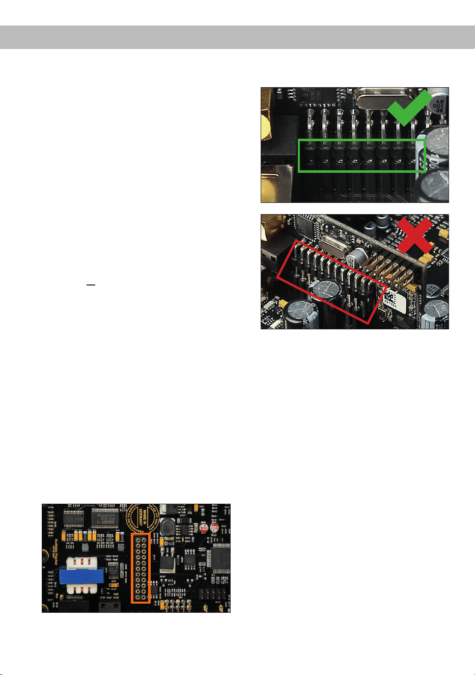
37
enInstalling Extension Card 2.0
By installing an Extension Card 2.0 (EC 2.0), the
amplier can be upgraded with additional inter-
faces – such as high-denition Bluetooth
®
audio
streaming, additional analog inputs, and other fea-
tures.
For installation, the device must be opened and the
cover panel of the EC 2.0 slot must be replaced.
Important: Only use EC 2.0 modules approved
for this device and install them exclusively in
the designated slot. Using incorrect modules or
installing them in the wrong location may cause
damage to the amplier, the Extension Card, the
vehicle’s radio system, or other components.
This section explains how to install and commission
an Extension Card 2.0 (EC 2.0) for initial use:
1. Disconnect connections
Disconnect all cable connections from the device.
2. Open amplier
Remove the side panel with the EC 2.0 slot by
loosening the three Phillips screws. Next, pull
the bottom plate out to the side.
3. Prepare the side panel
Remove the cover panel of the EC 2.0 from the
previously removed side panel by loosening the
two Allen screws on the back.
Now t the new cover panel supplied with the
EC 2.0. Ensure correct alignment and only
tighten the screws hand-tight.
4. Prepare EC 2.0
Prepare the module for installation according to
its instruction manual.
5. Insert EC 2.0 into the amplier
Insert the module into the designated socket
inside the device (see marking in the following
image).
Make sure that the module is installed properly
and all pins are fully inserted into the socket.
6. Reassemble the amplier
Reinsert the bottom plate and x the side panel
with the three screws.
7. Fix EC 2.0
Bolt the module to the side panel. Precise
mounting information will be found in the in-
struction manual of the respective EC 2.0.
8. Commissioning
Reconnect all cables and switch the device on.
The EC 2.0 is automatically detected by the
device and the module´s Status LED lights up
green.
9. Conguration in the DSP PC-Tool
The EC 2.0 can now be congured via the DSP
PC-Tool software.

38
Technical Data
Output power RMS (≤ 1% THD+N)
- @ 4 Ohms ..................................................................... Channels A - H: 65 Watts (min. 3 Ohms*)
Channels I - J : 75 Watts (min. 3 Ohms*)
- @ 2 Ohms .....................................................................Channels I - J : 125 Watts
Max. output power per channel** .................................... Channels A - H: up to 80 Watts RMS @ 4 Ohms
Channels I - J : up to 90 Watts RMS @ 4 Ohms
Channels I - J : up to 160 Watts RMS @ 2 Ohms
Amplier technology ........................................................Class GD
Inputs ............................................................................... 8 x Highlevel speaker input
1 x Optical SPDIF (12 - 96 kHz)
1 x Extension Card 2.0
Input sensitivity ................................................................ Channels A - F: 4 - 16 Volts
Channels G - H: 4 - 32 Volts
Input impedance ..............................................................9 - 33 Ohms with ADEP.3
Outputs ............................................................................ 10 x Speaker output
1 x RCA / Cinch
1 x Remote Out
Output voltage RCA / Cinch.............................................3 Volts RMS
Frequency response ........................................................15 Hz - 22,000 Hz
DSP resolution .................................................................64 Bit
DSP power ......................................................................295 MHz (1.2 billion MAC operations/sec.)
Sampling rate ..................................................................48 kHz
DSP type .........................................................................Audio signal processor
Signal converters ............................................................. A/D: BurrBrown
D/A: BurrBrown
Signal-to-noise ratio (A-weighted) ................................... Digital input: 105 dB
Analog input: 103 dB
Distortion (THD @ 1 kHz, 1 W into 4 Ohms) ...................< 0.015 %
Distortion (THD+N @ 1 kHz, 1 W into 4 Ohms) ..............< 0.02 %
Operating voltage ............................................................10.5 - 18 Volts (max. 5 sec. down to 6 Volts)
Power rating ....................................................................DC 12 V
60 A max.
Idle current.......................................................................500 mA
Max. remote output current .............................................500 mA
Operating temperature range ..........................................-40° C to +70° C
Fuse.................................................................................2 x 25 A LP-Mini-fuse (APS)
Additional features ........................................................... Class GD technology with dynamically controlled
power supply, 32 Bit CoProcessor, ADEP.3 circuit,
Start-Stop capability, Smart Control Port, USB-C,
Auto Remote switch
Dimensions (H x W x D) ..................................................46 x 145 x 163 mm / 1.81 x 5.71 x 6.42”
* DC resistance min. 3.0 Ohms
** In typical multi-channel applications

39
en
The warranty service is based on the statutory regulations. Defects and damage caused by overload or
improper handling are excluded from the warranty service. Any return can only take place following prior
consultation, in the original packaging together with a detailed description of the error and a valid proof of
purchase.
Technical modications, misprints and errors excepted! For damages on the vehicle and the device, caused
by handling errors of the device, we can’t assume liability.
Warranty disclaimer
This symbol means the product must not be discarded as household waste, and should be
delivered to an appropriate collection facility for recycling. Follow local rules and never dispose
of the product with normal household waste. Correct disposal of old products helps prevent
negative consequences for the environment and human health.
Correct disposal of this product
Trademarks
This product has been issued a CE marking. This means that the device is certied for use in
vehicles within the European Union (EU).
This product has been issued a UKCA marking. This means that the device is certied for use
in vehicles within the United Kingdom.
This product has been issued an EAC marking. This means that the device is certied for use
in vehicles within the Eurasian Customs Union.
Regulatory notes
The Bluetooth
®
word mark and logos are registered trademarks owned by Bluetooth SIG, Inc. and any use
of such marks by Audiotec Fischer GmbH is under license. Other trademarks and trade names are those
of their respective owners.

Audiotec Fischer GmbH
Hünegräben 26 - 28 · 57392 Schmallenberg · Germany
Tel.: +49 2972 9788 0 · Fax: +49 2972 9788 88
E-mail: match@audiotec-scher.com · Internet: www.audiotec-scher.com
Made in Germany
