

Visit our website at: https://www.harborfreight.com
email our technical support at: [email protected]
2421E-B
6"
BENCHTOP JOINTER
70303
tM
Owner’s Manual & Safety Instructions
Save This Manual Keep this manual for the safety warnings and precautions, assembly,
operating, inspection, maintenance and cleaning procedures. Write the product’s serial number in the
back of the manual near the assembly diagram (or month and year of purchase if product has no number).
Keep this manual and the receipt in a safe and dry place for future reference. 24h
When unpacking, make sure that the product is intact
and undamaged. If any parts are missing or broken,
please call 1-888-866-5797 as soon as possible.
Copyright
©
2023 by Harbor Freight Tools
®
. All rights reserved.
No portion of this manual or any artwork contained herein may be reproduced in
any shape or form without the express written consent of Harbor Freight Tools.
Diagrams within this manual may not be drawn proportionally. Due to continuing
improvements, actual product may differ slightly from the product described herein.
Tools required for assembly and service may not be included.
read this material before using this product.
Failure to do so can result in serious injury.
SaVe tHiS ManuaL.

Page 2 For technical questions, please call 1-888-866-5797. Item 70303
SaFety OperatiOn MaintenanceSetup
table of contents
Safety ......................................................... 2
Specifications ............................................. 6
Setup .......................................................... 6
Operation .................................................... 9
Maintenance .............................................. 12
Parts List and Diagram .............................. 17
Warranty .................................................... 20
tM
WarninG SyMBOLS anD DeFinitiOnS
This is the safety alert symbol. It is used to alert you to potential
personal injury hazards. Obey all safety messages that
follow this symbol to avoid possible injury or death.
Indicates a hazardous situation which, if not avoided,
will result in death or serious injury.
Indicates a hazardous situation which, if not avoided,
could result in death or serious injury.
Indicates a hazardous situation which, if not avoided,
could result in minor or moderate injury.
Addresses practices not related to personal injury.
iMpOrtant SaFety inFOrMatiOn
General tool Safety Warnings
read all safety warnings and instructions.
Failure to follow the warnings and instructions may result in electric shock, fire and/or serious injury.
Save all warnings and instructions for future reference.
1. KEEP GUARDS IN PLACE and in working order.
2. REMOVE ADJUSTING KEYS AND
WRENCHES. Form habit of checking to
see that keys and adjusting wrenches are
removed from tool before turning it on.
3. KEEP WORK AREA CLEAN.
Cluttered areas and benches invite accidents.
4. DON’T USE IN DANGEROUS ENVIRONMENT.
Don’t use power tools in damp or wet locations,
or expose them to rain. Keep work area well lighted.
5. KEEP CHILDREN AWAY. All visitors should
be kept safe distance from work area.
6. MAKE WORKSHOP KID PROOF with padlocks,
master switches, or by removing starter keys.
7. DON’T FORCE TOOL. It will do the job better
and safer at the rate for which it was designed.
8. USE RIGHT TOOL. Don’t force tool or attachment
to do a job for which it was not designed.

Page 3For technical questions, please call 1-888-866-5797.Item 70303
SaFetyOperatiOnMaintenance Setup
table a: recOMMenDeD MiniMuM Wire GauGe
FOr eXtenSiOn cOrDS
(120 VOLt)
naMepLate
aMpereS
(at full load)
eXtenSiOn cOrD
LenGtH
25′ 50′ 100′ 150′
0 – 6 18 16 16 14
6.1 – 10 18 16 14 12
10.1 – 12 16 16 14 12
12.1 – 16 14 12 Do not use.
9. USE PROPER EXTENSION CORD. Make sure your
extension cord is in good condition. When using
an extension cord, be sure to use one heavy
enough to carry the current your product will draw.
An undersized cord will cause a drop in line voltage
resulting in loss of power and overheating.
Table A shows the correct size to use depending
on cord length and nameplate ampere rating.
If in doubt, use the next heavier gauge.
The smaller the gauge number, the heavier the cord.
10. WEAR PROPER APPAREL. Do not wear
loose clothing, gloves, neckties, rings, bracelets,
or other jewelry which may get caught in moving
parts. Nonslip footwear is recommended.
Wear protective hair covering to contain long hair.
11. ALWAYS USE SAFETY GLASSES. Also use
face or dust mask if cutting operation is dusty.
Everyday eyeglasses only have impact resistant
lenses, they are NOT safety glasses.
12. SECURE WORK. Use clamps or a vise to
hold work when practical. It’s safer than using your
hand and it frees both hands to operate tool.
13. DON’T OVERREACH.
Keep proper footing and balance at all times.
14. MAINTAIN TOOLS WITH CARE. Keep
tools sharp and clean for best and safest
performance. Follow instructions for
lubricating and changing accessories.
15. DISCONNECT TOOLS before servicing;
when changing accessories, such as
blades, bits, cutters, and the like.
16. REDUCE THE RISK OF UNINTENTIONAL
STARTING. Make sure switch is in
off position before plugging in.
17. USE RECOMMENDED ACCESSORIES.
Consult the owner’s manual for recommended
accessories. The use of improper accessories
may cause risk of injury to persons.
18. NEVER STAND ON TOOL.
Serious injury could occur if the tool is tipped or
if the cutting tool is unintentionally contacted.
19. CHECK DAMAGED PARTS. Before further use
of the tool, a guard or other part that is damaged
should be carefully checked to determine that
it will operate properly and perform its intended
function – check for alignment of moving parts,
binding of moving parts, breakage of parts,
mounting, and any other conditions that may
affect its operation. A guard or other part that is
damaged should be properly repaired or replaced.
20. DIRECTION OF FEED.
Feed work into a blade or cutter against the
direction of rotation of the blade or cutter only.
21. NEVER LEAVE TOOL RUNNING UNATTENDED.
TURN POWER OFF. Don’t leave tool
until it comes to a complete stop.

Page 4 For technical questions, please call 1-888-866-5797. Item 70303
SaFety OperatiOn MaintenanceSetup
Grounding instructions
tO preVent eLectric SHOcK anD DeatH FrOM incOrrect
GrOunDinG Wire cOnnectiOn reaD anD FOLLOW tHeSe inStructiOnS:
110-120 Vac Grounded tools: tools with three prong plugs
1. In the event of a malfunction or breakdown,
grounding provides a path of least resistance for
electric current to reduce the risk of electric shock.
This tool is equipped with an electric cord having an
equipment-grounding conductor and a grounding
plug. The plug must be plugged into a matching
outlet that is properly installed and grounded in
accordance with all local codes and ordinances.
2. Do not modify the plug provided – if it will
not fit the outlet, have the proper outlet
installed by a qualified electrician.
3. Improper connection of the equipment-grounding
conductor can result in a risk of electric shock.
The conductor with insulation having an outer
surface that is green with or without yellow
stripes is the equipment-grounding conductor.
If repair or replacement of the electric cord or
plug is necessary, do not connect the equipment-
grounding conductor to a live terminal.
4. Check with a qualified electrician or service
personnel if the grounding instructions are
not completely understood, or if in doubt as
to whether the tool is properly grounded.
5. Use only 3-wire extension cords that
have 3-prong grounding plugs and 3-pole
receptacles that accept the tool’s plug.
6. Repair or replace damaged or
worn cord immediately.
Grounding
pin
125 Vac 3-prong plug and Outlet
(for up to 125 Vac and up to 15 a)
7. This tool is intended for use on a circuit that has
an outlet that looks like the one illustrated above in
125 Vac 3-prong plug and Outlet. The tool has
a grounding plug that looks like the plug illustrated
above in 125 Vac 3-prong plug and Outlet.
8. The outlet must be properly installed and grounded
in accordance with all codes and ordinances.
9. Do not use an adapter to connect
this tool to a different outlet.
Jointer Safety Warnings
For your Own Safety read instruction
Manual Before Operating Jointer
1. Wear eye protection.
2. Always keep cutter head and drive guards in
place and in proper operating condition.
3. Never make jointing or planing
cut deeper than 1/8 in.
4. Always use hold-down/push blocks for
jointing material narrower than 3 inches, or
planing material thinner than 3 inches.
5. Never perform jointing or planing cuts on pieces
shorter than 8 inches (203 mm) in length.
6. Do not perform jointing operations on
material shorter than 8 in, narrower than
3/4 in, or less than 1/4 in thick.
note: A jointing cut is a cut made to assist
in joining two pieces of wood.
7. Do not perform planing operations on material
shorter than 8 in, narrower than 3/4 in, or
wider than 6 in or thinner than 1/2 in.
note: A planing cut is a cut made to
smooth out defects in the wood’s surface.
8. Maintain the proper relationships of infeed and
outfeed table surfaces and cutter head knife path.
9. Support the workpiece adequately at all times during
operation; maintain control of the work at all times.
10. Do not back the work toward the infeed table.

Page 5For technical questions, please call 1-888-866-5797.Item 70303
SaFetyOperatiOnMaintenance Setup
11. Do not attempt to perform an abnormal
or little-used operation without study and
the use of adequate hold-down/push blocks,
jigs, fixtures, stops, and the like.
12. DO nOt Operate WitH any GuarD
DiSaBLeD, DaMaGeD, Or reMOVeD. Moving
guards must move freely and close instantly.
13. The use of accessories or attachments not
recommended by the manufacturer may
result in a risk of injury to persons.
14. When servicing use only identical replacement parts.
15. Remove the Safety Key after each use.
Store the Safety Key separate from
the tool and out of children's reach.
16. Only use safety equipment that has been approved
by an appropriate standards agency. Unapproved
safety equipment may not provide adequate
protection. Eye protection must be ANSI-approved
and breathing protection must be NIOSH-approved
for the specific hazards in the work area.
17. Stay alert, watch what you are doing and use
common sense when operating a power tool.
Do not use a power tool while you are tired or
under the influence of drugs, alcohol or medication.
A moment of inattention while operating power
tools may result in serious personal injury.
18. Industrial applications must follow OSHA guidelines.
19. Maintain labels and nameplates on the tool.
These carry important safety information.
If unreadable or missing, contact
Harbor Freight Tools for a replacement.
20. Avoid unintentional starting.
Prepare to begin work before turning on the tool.
21. People with pacemakers should consult their
physician(s) before use. Electromagnetic fields in
close proximity to heart pacemaker could cause
pacemaker interference or pacemaker failure.
22. The warnings, precautions, and instructions
discussed in this instruction manual cannot cover all
possible conditions and situations that may occur.
It must be understood by the operator that
common sense and caution are factors
which cannot be built into this product,
but must be supplied by the operator.
Vibration Safety
This tool vibrates during use. Repeated or
long-term exposure to vibration may cause
temporary or permanent physical injury,
particularly to the hands, arms and shoulders.
To reduce the risk of vibration-related injury:
1. Anyone using vibrating tools regularly or for an
extended period should first be examined by a
doctor and then have regular medical check-ups
to ensure medical problems are not being caused
or worsened from use. Pregnant women or
people who have impaired blood circulation to
the hand, past hand injuries, nervous system
disorders, diabetes, or Raynaud’s Disease should
not use this tool. If you feel any medical or
physical symptoms related to vibration (such as
tingling, numbness, and white or blue fingers),
seek medical advice as soon as possible.
2. Do not smoke during use. Nicotine reduces
the blood supply to the hands and fingers,
increasing the risk of vibration-related injury.
3. Use tools with the lowest vibration when there
is a choice between different processes.
4. Include vibration-free periods each day of work.
5. Grip workpiece as lightly as possible (while still
keeping safe control of it). Let the tool do the work.
6. To reduce vibration, maintain the tool as
explained in this manual. If any abnormal
vibration occurs, stop use immediately.
SaVe tHeSe inStructiOnS.

Page 6 For technical questions, please call 1-888-866-5797. Item 70303
SaFety OperatiOn MaintenanceSetup
Specifications
Electrical Rating 120V~ / 60Hz / 12A / Class I
Cutter Head No Load Speed n
0
: 9000/min
Cutter Head Dimensions and Types 6" Wide / 3 Rows of 4 Replaceable Square Inserts
Fence Stops 45°, 90°, 135°
Max. Cutting Depth 1/8"
Max. Cutting Width 6"
Min. Stock Length 10"
Min. Stock Width 3/4"
Min. Stock Thickness 1/2"
Min. Dust Collection Requirements 100 CFM, Ø2-1/2" OD Dust Port
Setup - Before use:
read the entire iMpOrtant SaFety inFOrMatiOn section at the beginning of this
manual including all text under subheadings therein before set up or use of this product.
tO preVent SeriOuS inJury FrOM acciDentaL OperatiOn:
turn the power Switch of the tool off, remove the Safety Key, and unplug the tool
from its electrical outlet before performing any procedure in this section.
note: For additional information regarding the parts listed in the following pages,
refer to the Assembly Diagram near the end of this manual.
assembly/Mounting
1. Assemble Handles to Infeed / Outfeed
Tables with M8x30 Cap Screw Assemblies
using 6mm Hex Wrench.
Infeed / Outfeed
table
Handle
2. Place Jointer on sturdy bench. Jointer can be
mounted to bench using four Mounting Holes in
base and appropriate hardware (sold separately).
Mounting Holes
(two on each side)
3. Assemble Carriage Support to back
of Jointer with M8x20 Cap Screw
Assemblies using 6mm Hex Wrench.
carriage
Support

Page 7For technical questions, please call 1-888-866-5797.Item 70303
SaFetyOperatiOnMaintenance Setup
4. Assemble Fence Tilt Lock with
Beveled Washer to Carriage.
carriage
Fence
tilt Lock
Beveled
Washer
5. Remove M6x20 Cap Screws and Spring Washers
from back of Fence with 5mm Hex Wrench.
note: Slight radius in center of Fence will face DOWN
towards Infeed / Outfeed Tables when assembled.
cap Screws
/ Spring
Washers
Fence
radius
6. Assemble Carriage and Fence assemblies
with M6x20 Cap Screws and Spring
Washers removed in Step 5.
carriage
assembly
Fence
cap Screws
/ Spring
Washers
7. Assemble Carriage Assembly and Support:
a. Assemble Lock Plate to Carriage Support
with Fence Carriage Lock and Beveled
Washer, making sure Lock Plate pins are
underneath Carriage support edge. Do not
tighten Fence Carriage Lock at this time.
b. Slide Carriage assembly onto dovetail of
Carriage Support and Lock Plate. Tighten
Fence Carriage Lock to lock Carriage position.
carriage
carriage
Support
Support
carriage
carriage
assembly
assembly
Fence
Fence
carriage
carriage
Lock
Lock
Lock
Lock
plate
plate
Beveled
Beveled
Washer
Washer
Dust collection
Install dust bag or dust collection system
(sold separately) to the Dust Port.
Page 8 For technical questions, please call 1-888-866-5797. Item 70303
SaFety OperatiOn MaintenanceSetup
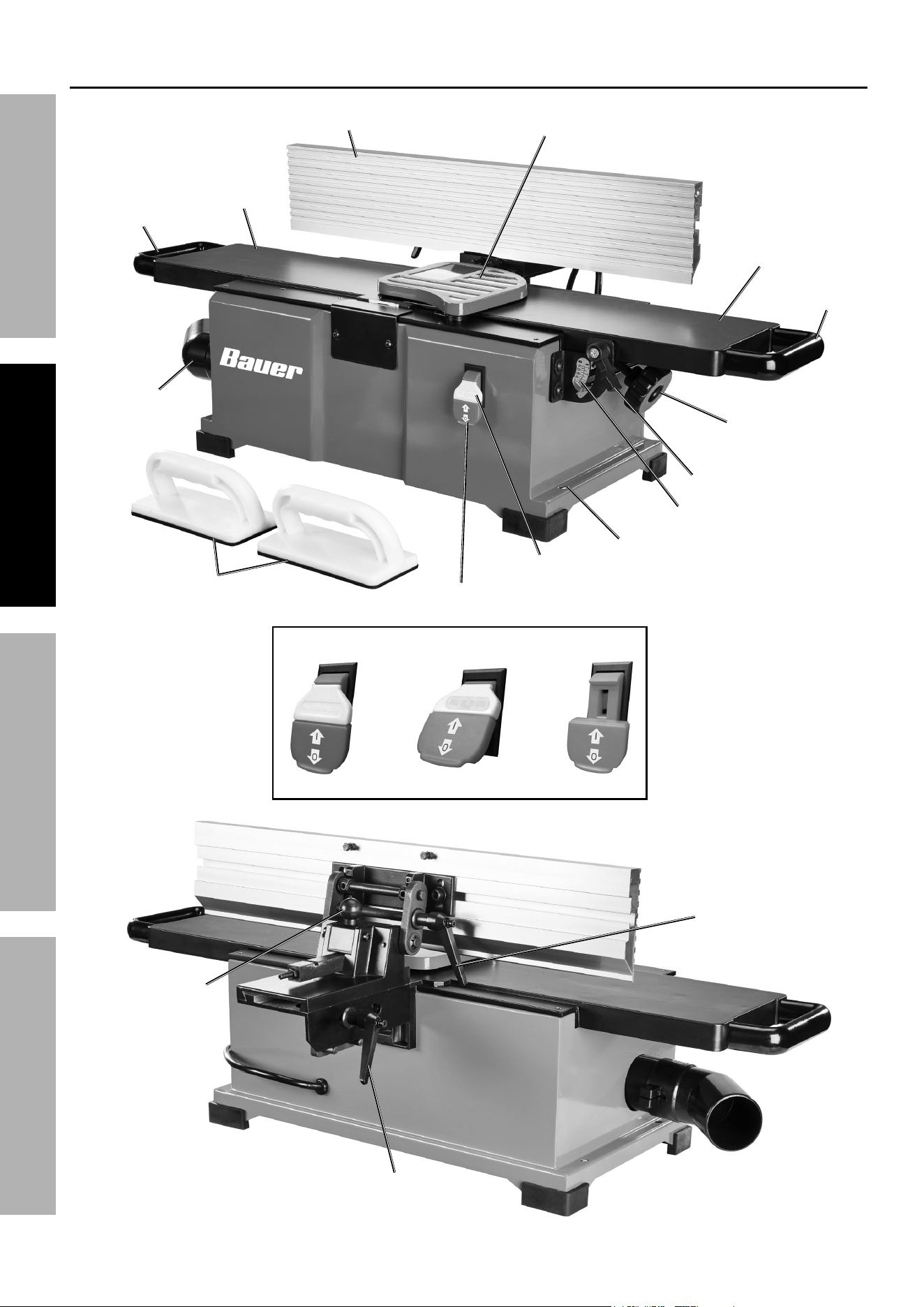
Functions
power
Switch
Safety
Key
infeed
table
Outfeed
table
Fence
cutter Head
Guard
Handle
Handle
Dust port
(Ø2-1/2")
push
Blocks
Off
On
Locked
power Switch positions
Mounting
Hole (4)
infeed
adjustment Knob
Fence tilt
Lock
Fence carriage
Lock
cut Depth
Scale
table Lock
Fence
Limit Knob

Page 9For technical questions, please call 1-888-866-5797.Item 70303
SaFetyOperatiOnMaintenance Setup
Operating instructions
read the entire iMpOrtant SaFety inFOrMatiOn section at the beginning of this
manual including all text under subheadings therein before set up or use of this product.
tool Set up
tO preVent SeriOuS inJury FrOM acciDentaL OperatiOn:
turn the power Switch of the tool off, remove the Safety Key, and unplug the tool
from its electrical outlet before performing any procedure in this section.
tO preVent SeriOuS inJury:
DO nOt Operate WitH any GuarD DiSaBLeD, DaMaGeD, Or reMOVeD.
Moving guards must move freely and close instantly.
Workpiece and Work area Set up
1. Designate a work area that is clean and well-lit.
The work area must not allow access by children
or pets to prevent distraction and injury.
2. Route the power cord along a safe route to reach
the work area without creating a tripping hazard or
exposing the power cord to possible damage. The
power cord must reach the work area with enough
extra length to allow free movement while working.
3. There must not be objects, such as utility lines,
nearby that will present a hazard while working.
Setting cut Depth
1. Loosen Table Lock.
2. Turn Infeed Adjustment Knob to raise or
lower Infeed Table to desired cut depth.
3. Tighten Table Lock.
note: Use Depth Adjustment Scale as
a reference to indicate cut depth.
table
table
Lock
Lock
infeed
infeed
adjustment Knob
adjustment Knob
cut Depth
cut Depth
Scale
Scale
Setting Zero Stop
Use the Zero Stop to consistently raise Infeed
Table to same height as Outfeed Table.
1. Loosen Nut on Zero Stop Set Screw
(located above Infeed Adjustment Knob)
with 10mm wrench (sold separately).
2. Adjust Zero Stop Set Screw with 3mm hex wrench
(sold separately) so it does not contact Infeed Table.
3. Loosen Table Lock, Place straightedge (sold
separately) on top of Outfeed / Infeed tables. Adjust
Infeed Table height until both have even contact.
4. Adjust Zero Stop Set Screw until it contacts
Infeed Table, then tighten Nut.
Zero Stop
Zero Stop
Set Screw
Set Screw
nut
nut

Page 10 For technical questions, please call 1-888-866-5797. Item 70303
SaFety OperatiOn MaintenanceSetup
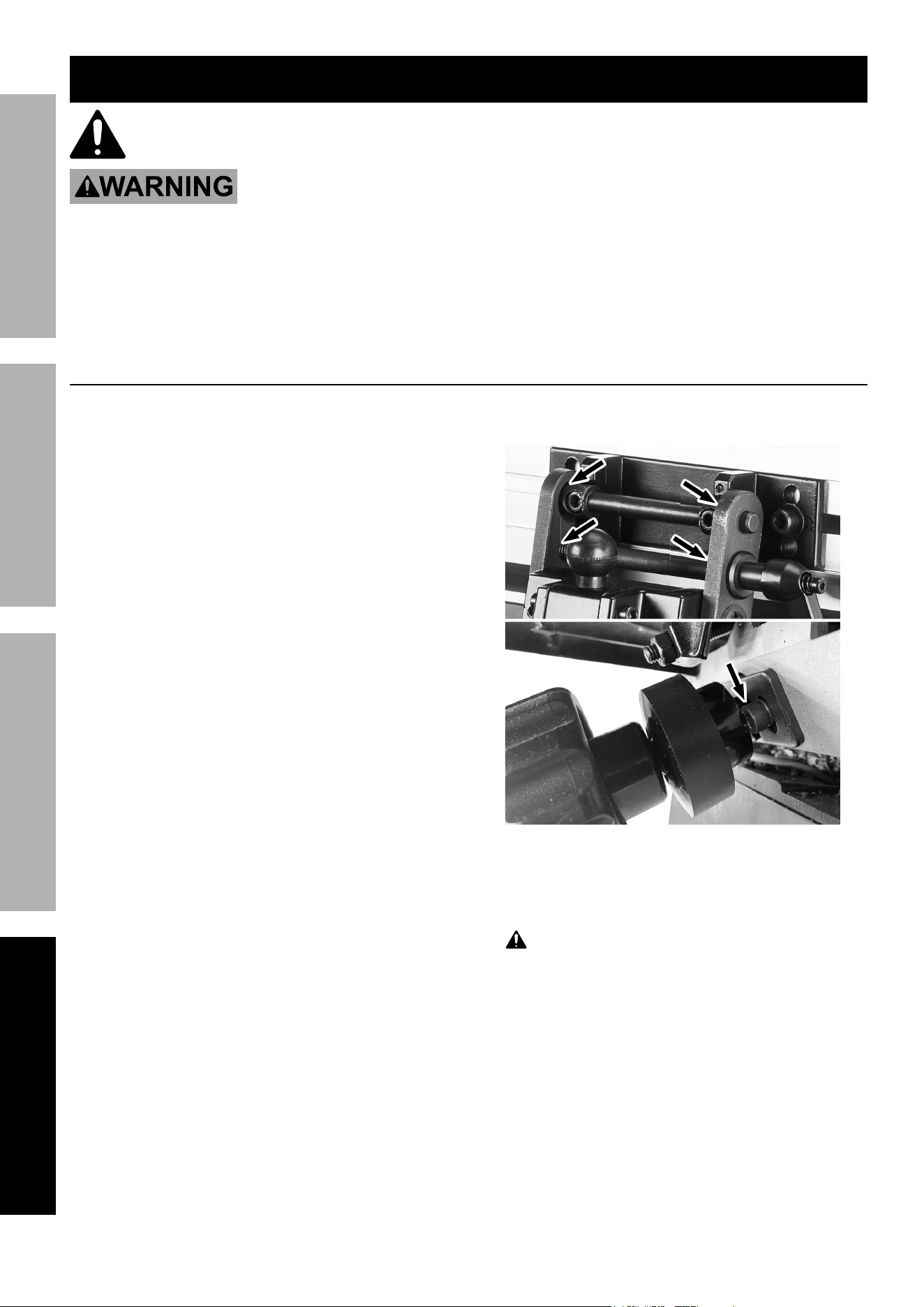
Setting Fence Stops
Use a combination square (sold separately) to set Fence stops.
Setting 90° Fence stop:
1. Loosen Fence Tilt Lock.
2. Lift Fence Limit Knob, slide Limit Block
in, release Knob to lock in last slot
(illustration shows first slot locked).
note: Limit Block is only used for
positioning Fence for 90° cuts.
3. Tighten Fence Tilt Lock. Use square to confirm
Fence is 90° to Infeed / Outfeed Tables.
4. If Fence is NOT 90° to Infeed / Outfeed Tables:
a. Loosen Fence Tilt Lock and Nut. Keep
Limit Block first slot locked.
b. Use square to adjust Fence 90° to
Infeed / Outfeed Tables. Tighten Fence Tilt Lock.
c. Turn Limit Block Shaft until it
contacts Fence; tighten Nut.
Fence tilt Fence tilt
Lock Lock
Fence Fence
Limit KnobLimit Knob
LimitLimit
Block Block
Limit Limit
Block Block
ShaftShaft
nutnut
Setting 45° Fence stop:
1. Lift Fence Limit Knob, slide Limit Block out
and release Knob to lock in first slot.
note: Limit Block is not used for
positioning Fence for angled cuts.
2. Loosen Fence Tilt Lock; tilt top of Fence
down towards Infeed / Outfeed Tables.
3. Use square to confirm Fence is 45°
to Infeed / Outfeed Tables.
4. If Fence is NOT 45° to Infeed / Outfeed Tables:
a. Use square to adjust Fence 45° to
Infeed / Outfeed Tables. Tighten Fence Tilt Lock.
b. Loosen Nuts on Inner Stop Bolts. Adjust
Stop Bolts to touch Fence. Tighten Nuts.
Fence tilt Fence tilt
Lock Lock
Fence Fence
Limit KnobLimit Knob
LimitLimit
Block Block
Fence Fence
carriagecarriage
nutsnuts
inner inner
Stop BoltsStop Bolts
Setting 135° Fence stop:
1. Lift Fence Limit Knob, slide Limit Block out
and release Knob to lock in first slot.
note: Limit Block is not used for
positioning Fence for angled cuts.
2. Loosen Fence Tilt Lock; tilt top of Fence
down away from Infeed / Outfeed Tables.
3. Use square to confirm Fence is 135°
to Infeed / Outfeed Tables.
4. If Fence is NOT 135° to Infeed / Outfeed Tables:
a. Use square to adjust Fence 135° to
Infeed / Outfeed Tables. Tighten Fence Tilt Lock.
b. Loosen Nuts on Outer Stop Bolts.
Adjust Stop Bolts to touch Fence
Pivot assembly. Tighten Nuts.
Fence tilt Fence tilt
Lock Lock
Fence Fence
Limit KnobLimit Knob
LimitLimit
Block Block
nutsnuts
Outer Outer
Stop BoltsStop Bolts
Fence Fence
pivot pivot
assy.assy.

Page 11For technical questions, please call 1-888-866-5797.Item 70303
SaFetyOperatiOnMaintenance Setup
General Operating instructions
note: Practice on scrap material until
familiar with Jointer′s capabilities.
cautiOn! concave workpiece sides must face
table and Fence for stability when cutting.
WarninG! tO preVent inJury: Do not use blunt
or damaged cutter Head inserts.
Keep hands at least 4″ away from cutter Head.
WarninG! tO preVent SeriOuS inJury FrOM
KicKBacK: Do not turn Jointer on with workpiece
contacting cutter Head.
Do not exceed a cut depth of 1/8".
Stand on side nearest the switch and to the side.
1. Adjust Infeed Table to desired cut depth.
2. Adjust Fence:
a. edge Jointing: Slide Limit Block in,
release Knob to lock in last slot to
adjust Fence to 90° position.
b. Bevel cutting: Slide Limit Block out
and release Knob to lock in first slot and
adjust Fence to desired cut angle.
3. Tighten Fence Carriage and Tilt Locks.
4. Make sure that the Power Switch
is in the off-position, then plug in the tool.
5. Place workpiece against Fence and Infeed Table.
6. Insert the Safety Key into the Switch. Turn on tool.
7. Use Push Blocks to feed workpiece
across Cutter Head, keeping it in firm
contact with Fence and Table.
edge Jointingedge Jointing
Bevel cuttingBevel cutting
8. Repeat previous step as needed:
a. edge Jointing: Repeat previous
step as needed until edge is flat.
b. Bevel cutting: Repeat previous step as
needed to produce satisfactory edge.
nOtice: To prevent damage from clogging, empty dust
collection system and clean Cutter Head frequently.
9. To prevent accidents, turn off the tool,
remove the Safety Key, and unplug the tool from
its electrical outlet after use. Clean, then store
the tool indoors out of children’s reach. Store the
Safety Key separately also out of children's reach.
Page 12 For technical questions, please call 1-888-866-5797. Item 70303
SaFety OperatiOn MaintenanceSetup
Maintenance and Servicing
procedures not specifically explained in this manual must
be performed only by a qualified technician.
tO preVent SeriOuS inJury FrOM acciDentaL OperatiOn:
turn the power Switch of the tool off, remove the Safety Key, and unplug the tool
from its electrical outlet before performing any procedure in this section.
tO preVent SeriOuS inJury FrOM tOOL FaiLure:
Do not use damaged equipment. if abnormal noise or vibration
occurs, have the problem corrected before further use.
cleaning, Maintenance, and Lubrication
1. BeFOre eacH uSe, inspect the general
condition of the tool. Check for:
• loose hardware,
• misalignment or binding of moving parts,
• cracked or broken parts,
• damaged electrical wiring, and
• any other condition that may
affect its safe operation.
2. aFter uSe, Wear ANSI-approved safety goggles
and NIOSH-approved breathing protection, blow
debris from Jointer using dry compressed air.
a. Remove resin residue with
pitch and gum remover.
b. Empty dust collection system (if applicable).
c. Wipe external surfaces with clean cloth.
d. Wax tables with a non-silicone paste
wax to prevent staining the wood.
3. periODicaLLy, Lubricate with light machine oil
one or two drops as indicated. Wipe off excess.
4. periODicaLLy, wear ANSI-approved
safety goggles and NIOSH-approved
breathing protection and blow dust out of
the motor vents using dry compressed air.
5.
WarninG! tO preVent SeriOuS
inJury: if the supply cord of this power
tool is damaged, it must be replaced only
by a qualified service technician.

Page 13For technical questions, please call 1-888-866-5797.Item 70303
SaFetyOperatiOnMaintenance Setup
cutter Head insert rotation/replacement
cautiOn! Wear heavy duty gloves
when handling cutting inserts.
1. Lower Infeed Table as far as possible.
2. Remove bottom Base Cover.
3. Rotate Cutter Head Guard outward and use a
small flat head screwdriver (sold separately)
or wood block to hold it in place.
4. Rotate Cutter Head Pulley to rotate Cutter
Head and expose Cutting Inserts.
5. Use T25 Torx Wrench to remove Cutting inserts.
6. Clean Cutter Head Inserts, Torx Screws,
Cutting Insert pockets, and surrounding
areas of saw dust or debris.
cuttingcutting
insertinsert
cuttercutter
HeadHead
t25 torxt25 torx
ScrewScrew
cutter Headcutter Head
GuardGuard
note: Debris in the Cutting Insert pockets will raise
the Cutting Inserts when installed and produce
unsatisfactory results. Wear ANSI-approved
safety goggles and NIOSH-approved
breathing protection and blow debris out
using dry low-pressure compressed air.
7. Lubricate Torx Screws with small amount
of light machine oil. Wipe off excess.
8. Re-install Cutting Inserts with a sharp cutting
edge facing outward. If all four cutting edges
are dull, replace with a new Insert.
note: Cutting Inserts are numbered or have a
reference mark on them to allow operator to keep
track of how many times the Insert has been rotated.
9. Torque Torx Screws to 48 inch pounds.
10. Replace bottom Base Cover.

Page 14 For technical questions, please call 1-888-866-5797. Item 70303
SaFety OperatiOn MaintenanceSetup
troubleshooting
problem possible causes Likely Solutions
Tool will not start. 1. Cord not connected.
2. No power at outlet.
3. Tool’s thermal reset breaker
tripped (if equipped).
4. Internal damage or wear. (Carbon
brushes or switch, for example.)
1. Check that cord is plugged in.
2. Check power at outlet. If outlet is unpowered,
turn off tool and check circuit breaker.
If breaker is tripped, make sure circuit is right
capacity for tool and circuit has no other loads.
3. Turn off tool and allow to cool.
Press reset button on tool.
4. Have technician service tool.
Torn, ragged,
rough or
raised grain.
1. Blades dull or damaged.
2. Cut is too heavy.
3. Blades cutting against grain.
4. Wood has a high moisture content.
1. Replace blades.
2. Reduce depth of cut.
3. Cut with grain.
4. Use dry wood.
Tool operates
slowly.
Extension cord too long or
wire size too small.
Eliminate use of extension cord. If an extension cord
is needed, use one with the proper diameter for its
length and load. See table a on page 3.
Performance
decreases
over time.
1. Accessory dull or damaged.
2. Carbon brushes worn or damaged.
1. Keep cutting accessories sharp.
Replace as needed.
2. Have qualified technician replace brushes.
Excessive noise
or rattling.
Internal damage or wear. (Carbon
brushes or bearings, for example.)
Have technician service tool.
Overheating. 1. Forcing machine to work too fast.
2. Accessory dull or damaged.
3. Blocked motor housing vents.
4. Motor being strained by long or
small diameter extension cord.
1. Allow machine to work at its own rate.
2. Keep cutting accessories sharp.
Replace as needed.
3. Wear ANSI-approved safety goggles and
NIOSH-approved dust mask/respirator while
blowing dust out of motor using compressed air.
4. Eliminate use of extension cord.
If an extension cord is needed, use one with
the proper diameter for its length and load.
See table a on page 3.
Belt Slipping Loose belt Replace belt.
Excessive
dust in air
Leaking bag or loose connection. Check connections or replace collection bag.
Follow all safety precautions whenever diagnosing or servicing the tool.
Disconnect power supply and remove the Safety Key before service.

Page 15For technical questions, please call 1-888-866-5797.Item 70303
SaFetyOperatiOnMaintenance Setup
record product’s Serial number Here:
note: if product has no serial number, record month and year of purchase instead.
note: Some parts are listed and shown for illustration purposes only, and are not
available individually as replacement parts. Reference UPC 193175495303.

Page 16 For technical questions, please call 1-888-866-5797. Item 70303
SaFety OperatiOn MaintenanceSetup
pLeaSe reaD tHe FOLLOWinG careFuLLy
THE MANUFACTURER AND/OR DISTRIBUTOR HAS PROVIDED THE PARTS LIST AND ASSEMBLY DIAGRAM
IN THIS MANUAL AS A REFERENCE TOOL ONLY. NEITHER THE MANUFACTURER OR DISTRIBUTOR
MAKES ANY REPRESENTATION OR WARRANTY OF ANY KIND TO THE BUYER THAT HE OR SHE IS
QUALIFIED TO MAKE ANY REPAIRS TO THE PRODUCT, OR THAT HE OR SHE IS QUALIFIED TO REPLACE
ANY PARTS OF THE PRODUCT. IN FACT, THE MANUFACTURER AND/OR DISTRIBUTOR EXPRESSLY
STATES THAT ALL REPAIRS AND PARTS REPLACEMENTS SHOULD BE UNDERTAKEN BY CERTIFIED AND
LICENSED TECHNICIANS, AND NOT BY THE BUYER. THE BUYER ASSUMES ALL RISK AND LIABILITY
ARISING OUT OF HIS OR HER REPAIRS TO THE ORIGINAL PRODUCT OR REPLACEMENT PARTS
THERETO, OR ARISING OUT OF HIS OR HER INSTALLATION OF REPLACEMENT PARTS THERETO.

Page 17For technical questions, please call 1-888-866-5797.Item 70303
SaFetyOperatiOnMaintenance Setup
parts List and Diagram
parts List
part Description Qty
1
Outfeed Table
1
2
Fence
1
3
Fence Mounting Bracket
1
4
Right Pivot Bar
1
5
Left Pivot Bar
1
6
Pivot Shaft
1
7
Carriage Shaft
1
8
Fence Limit Knob
1
9
Position Block
1
10
Compression Spring
1
11
Handle
2
12
Limit Block
1
13
Limit Block Shaft
1
14
Carriage
1
15
Fence Tilt Lock
1
16
Carriage Support
1
17
Lock Plate
1
18
Alignment Pin
2
19
Table Pin
4
20
Frame Pin
4
21
Pin Bracket
4
22
Infeed Table
1
23
Table Sub Frame
1
24
Dial Support Plate
1
25
Infeed Adjustment Knob
1
26
Lifting Screw Rod
1
27
Motor
1
28
Motor Pulley
1
29
Motor Mounting Plate
1
30
Cord Clamp
1
31
Cutter Head Guard
1
32
Rubber Stop
1
33
Torsion Spring
1
34
Roll Pin
1
35
M8x20 Cap Screw Assembly
2
36
Cutter Head Assembly
1
36.1
Cutting Insert
15
36.2
Flat Head Torx Screw
15
36.3
Cutter Head
1
36.4
T-Handle T25 Torx Wrench
1
37
Compression Spring
1
38
Inward Stop Bolt
2
39
Cap Screw Assembly
4
40
Cutter Head Pulley
1
41
Nut
2
42
Cable Clamp
1
43
Blower Port
1
44
Blower Impeller
1
45
Exterior Retaining Ring
1
46
Blower Mounting Plate
1
47
Impeller Shaft
1
48
Blower Pulley
1
49
Spacer
1
50
Ball Bearing
2
51
Chip Chute
1
52
Base Cover
1
53
Push Block
1
54
Power Switch / Safety Key
1
part Description Qty
55
Position Shaft
1
56
Cap Screw Assembly
10
57
Spring Washer
9
58
Flat Washer
3
59
Screw
11
60
Flat Washer
2
61
Flat Washer
1
62
Cap Screw
8
63
Screw
1
64
Flat Washer
2
65
Cap Screw
2
66
Cap Screw
4
67
Hex Bolt
2
68
Nut
4
69
Screw
2
70
Nut
3
71
Cap Screw
1
72
V-Belt
1
73
Nut
1
74
Hex Bolt
1
75
Push Nut
2
76
E-Clip
4
77
Front Fixture Seat
1
78
Rear Fixture Seat
1
79
Zero Stop Set Screw
2
80
Set Screw
4
81
Set Screw
2
82
Screw
6
83
Screw
1
84
Exterior Tooth Washer
2
85
Spring Washer
4
86
Retainer Washer
1
87
Ball Bearing
2
88
Strain Relief
1
89
Power Cord
1
90
Belt Pulley Cover
1
91
V-Belt
1
92
Dust Port Assembly
1
92.1
Cross Head Screw
1
92.2
Dust Port Ø2-1/2"
1
93
Flat Washer
9
94
Cut Depth Scale
1
95
Pointer 1
1
96
Pointer 2
1
97
5mm Hex Wrench
1
98
Cap Screw
6
99
Set Screw
2
100
Base
1
101
Switch Mounting Plate
1
102
Rubber Pad-Left
2
103
Rubber Pad-Right
2
104
Guard Plate
1
105
Cap Screw Assembly
3
106
Taping Screw
6
107
6mm Hex Wrench
1
108
M8x30 Cap Screw Assembly
4
109
Beveled Washer
2
110
Sponge Gasket
1

Page 18 For technical questions, please call 1-888-866-5797. Item 70303
SaFety OperatiOn MaintenanceSetup
part Description Qty
111 Table Locking Screw
1
112 Fence Carriage Lock
1
113 Table Lock
1
114 Brush
1
115 Screw
1
part Description Qty
116 Anti Slip Washer
2
117 Cross Head Screw
2
118 Step Screw
1
119 Compression Spring
1
120 Copper Bushing
1

Page 19For technical questions, please call 1-888-866-5797.Item 70303
SaFetyOperatiOnMaintenance Setup
assembly Diagram

Limited 90 Day Warranty
Harbor Freight Tools Co. makes every effort to assure that its products meet high quality and durability standards,
and warrants to the original purchaser that this product is free from defects in materials and workmanship for the
period of 90 days from the date of purchase. This warranty does not apply to damage due directly or indirectly,
to misuse, abuse, negligence or accidents, repairs or alterations outside our facilities, criminal activity, improper
installation, normal wear and tear, or to lack of maintenance. We shall in no event be liable for death, injuries
to persons or property, or for incidental, contingent, special or consequential damages arising from the use of
our product. Some states do not allow the exclusion or limitation of incidental or consequential damages, so the
above limitation of exclusion may not apply to you. THIS WARRANTY IS EXPRESSLY IN LIEU OF ALL OTHER
WARRANTIES, EXPRESS OR IMPLIED, INCLUDING THE WARRANTIES OF MERCHANTABILITY AND FITNESS.
To take advantage of this warranty, the product or part must be returned to us with transportation charges
prepaid. Proof of purchase date and an explanation of the complaint must accompany the merchandise.
If our inspection verifies the defect, we will either repair or replace the product at our election or we may
elect to refund the purchase price if we cannot readily and quickly provide you with a replacement. We will
return repaired products at our expense, but if we determine there is no defect, or that the defect resulted
from causes not within the scope of our warranty, then you must bear the cost of returning the product.
This warranty gives you specific legal rights and you may also have other rights which vary from state to state.
26677 agoura road • calabasas, ca 91302 • 1-888-866-5797
tM