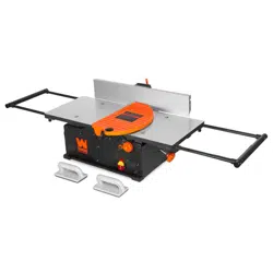
BENCHTOP JOINTER
WITH SPIRAL CUTTERHEAD
Instruction Manual
IMPORTANT: Your new tool has been engineered and manufactured to WEN’s highest standards for dependability,
ease of operation, and operator safety. When properly cared for, this product will supply you years of rugged,
trouble-free performance. Pay close attention to the rules for safe operation, warnings, and cautions. If you use
your tool properly and for its intended purpose, you will enjoy years of safe, reliable service.
NEED HELP? CONTACT US!
Have product questions? Need technical support? Please feel free to contact us:
TECHSUPPOR[email protected]1-847-429-9263 (M-F 8AM-5PM CST)
For replacement parts and the most up-to-date instruction manuals, visit WENPRODUCTS.COM
MODEL JT1020H, JT1224H

CONTENTS
WELCOME 3
Introduction ..................................................................................................... 3
Specifications ................................................................................................... 3
SAFETY 4
General Safety Rules ........................................................................................ 4
Jointer Safety Warnings ................................................................................... 6
Electrical Information ....................................................................................... 8
BEFORE OPERATING 9
Unpacking & Packing List .................................................................................9
Know Your Jointer ......................................................................................... 10
Assembly & Adjustments ............................................................................... 11
OPERATION & MAINTENANCE 14
Operation ....................................................................................................... 14
Maintenance ....................................................................................................16
Troubleshooting Guide ................................................................................... 18
Exploded View & Parts List .............................................................................19
Warranty Statement ........................................................................................25
2
To purchase accessories for your tool, visit WENPRODUCTS.COM
Replacement Helical Blades (Part No. BP510H)
4-1/4" x 24" Cast Iron Fence (Model JTA424)
Push Block and Push Stick Safety Set (Model WA0001)

SPECIFICATIONS
INTRODUCTION
Thanks for purchasing the WEN Benchtop Jointer. We know you are excited to put your tool to work, but first, please
take a moment to read through the manual. Safe operation of this tool requires that you read and understand this
operator’s manual and all the labels affixed to the tool. This manual provides information regarding potential safety
concerns, as well as helpful assembly and operating instructions for your tool.
NOTE: The following safety information is not meant to cover all possible conditions and situations that may occur.
WEN reserves the right to change this product and specifications at any time without prior notice.
At WEN, we are continuously improving our products. If you find that your tool does not exactly match this manual,
please visit wenproducts.com for the most up-to-date manual or contact our customer service at 1-847-429-9263.
Keep this manual available to all users during the entire life of the tool and review it frequently to maximize
safety for both yourself and others.
Indicates danger, warning, or caution. The safety symbols and the explanations with them deserve your
careful attention and understanding. Always follow the safety precautions to reduce the risk of fire, electric shock
or personal injury. However, please note that these instructions and warnings are not substitutes for proper ac-
cident prevention measures.
3
Model Number JT1020H JT1224H
Motor 120V AC, 60 Hz, 12A 120V AC, 60 Hz, 12A
Cutterhead Rotation Speed 11,000 RPM 11,000 RPM
Max Cutting Width 10 in. 12 Inches
Max Cutting Depth 1/8 in.* 1/8 in.*
Recommended Cutting Depth 1/32 in. 1/32 in.
Number of Blades 20 24
Table Size 10-3/16 in. x 34 in. (54 in. fully
extended)
12-3/16 in. x 34 in. (54 in. fully extended)
Fence Size 4-1/4 in. x 24 in. 4-1/4 in. x 24 in.
Dust Port Diameter 2-1/2, 4 in. 2-1/2, 4 in.
Fence Bevel 90° - 135° 90° - 135°
Product Dimensions 54 in. x 21-3/4 in. x 13-1/4 in. 54 in. x 23-3/4 in. x 13-1/4 in.
Weight 79.50 lbs 87.10 lbs
*When jointing boards over 6 inches, reduce maximum cutting depth by 1/32 inch per inch.

GENERAL SAFETY RULES
WORK AREA SAFETY
1. Keep work area clean and well lit. Cluttered or dark
areas invite accidents.
2. Do not operate power tools in explosive atmo-
spheres, such as in the presence of flammable liquids,
gases or dust. Power tools create sparks which may ig-
nite the dust or fumes.
3. Keep children and bystanders away while operating
a power tool. Distractions can cause you to lose control.
ELECTRICAL SAFETY
1. Power tool plugs must match the outlet. Never mod-
ify the plug in any way. Do not use any adapter plugs
with earthed (grounded) power tools. Unmodified plugs
and matching outlets will reduce risk of electric shock.
2. Avoid body contact with earthed or grounded surfac-
es such as pipes, radiators, ranges and refrigerators.
There is an increased risk of electric shock if your body
is earthed or grounded.
3. Do not expose power tools to rain or wet conditions.
Water entering a power tool will increase the risk of elec-
tric shock.
4. Do not abuse the cord. Never use the cord for car-
rying, pulling or unplugging the power tool. Keep cord
away from heat, oil, sharp edges or moving parts.
Damaged or entangled cords increase the risk of electric
shock.
5. When operating a power tool outdoors, use an ex-
tension cord suitable for outdoor use. Use of a cord
suitable for outdoor use reduces the risk of electric
shock.
6. If operating a power tool in a damp location is un-
avoidable, use a ground fault circuit interrupter (GFCI)
protected supply. Use of a GFCI reduces the risk of elec-
tric shock.
PERSONAL SAFETY
1. Stay alert, watch what you are doing and use com-
mon sense when operating a power tool. Do not use a
power tool while you are tired or under the influence
of drugs, alcohol or medication. A moment of inatten-
tion while operating power tools may result in serious
personal injury.
2. Use personal protective equipment. Always wear
eye protection. Protective equipment such as a respira-
tory mask, non-skid safety shoes and hearing protection
used for appropriate conditions will reduce the risk of
personal injury.
3. Prevent unintentional starting. Ensure the switch is
in the off-position before connecting to power source
and/or battery pack, picking up or carrying the tool.
Carrying power tools with your finger on the switch or
energizing power tools that have the switch on invites
accidents.
4. Remove any adjusting key or wrench before turning
the power tool on. A wrench or a key left attached to a
rotating part of the power tool may result in personal
injury.
5. Do not overreach. Keep proper footing and balance
at all times. This enables better control of the power
tool in unexpected situations.
6. Dress properly. Do not wear loose clothing or jew-
elry. Keep your hair and clothing away from moving
parts. Loose clothes, jewelry or long hair can be caught
in moving parts.
Safety is a combination of common sense, staying alert and knowing how your item works. The term “power tool”
in the warnings refers to your mains-operated (corded) power tool or battery-operated (cordless) power tool.
SAVE THESE SAFETY INSTRUCTIONS.
WARNING! Read all safety warnings and all instructions. Failure to follow the warnings and instructions may
result in electric shock, fire and/or serious injury.
4

GENERAL SAFETY RULES
7. If devices are provided for the connection of dust
extraction and collection facilities, ensure these are
connected and properly used. Use of dust collection
can reduce dust-related hazards.
POWER TOOL USE AND CARE
1. Do not force the power tool. Use the correct power
tool for your application. The correct power tool will
do the job better and safer at the rate for which it was
designed.
2. Do not use the power tool if the switch does not turn
it on and off. Any power tool that cannot be controlled
with the switch is dangerous and must be repaired.
3. Disconnect the plug from the power source and/or
the battery pack from the power tool before making
any adjustments, changing accessories, or storing
power tools. Such preventive safety measures reduce
the risk of starting the power tool accidentally.
4. Store idle power tools out of the reach of children
and do not allow persons unfamiliar with the power
tool or these instructions to operate the power tool.
Power tools are dangerous in the hands of untrained us-
ers.
5. Maintain power tools. Check for misalignment or
binding of moving parts, breakage of parts and any
other condition that may affect the power tool’s opera-
tion. If damaged, have the power tool repaired before
use. Many accidents are caused by poorly maintained
power tools.
6. Keep cutting tools sharp and clean. Properly main-
tained cutting tools with sharp cutting edges are less
likely to bind and are easier to control.
7. Use the power tool, accessories and tool bits, etc.
in accordance with these instructions, taking into ac-
count the working conditions and the work to be per-
formed. Use of the power tool for operations different
from those intended could result in a hazardous situa-
tion.
8. Use clamps to secure your workpiece to a stable
surface. Holding a workpiece by hand or using your
body to support it may lead to loss of control.
9. KEEP GUARDS IN PLACE and in working order.
SERVICE
1. Have your power tool serviced by a qualified repair
person using only identical replacement parts. This
will ensure that the safety of the power tool is main-
tained.
CALIFORNIA PROPOSITION 65 WARNING
Some dust created by power sanding, sawing, grinding,
drilling, and other construction activities may contain
chemicals, including lead, known to the State of Califor-
nia to cause cancer, birth defects, or other reproductive
harm. Wash hands after handling. Some examples of
these chemicals are:
• Lead from lead-based paints.
• Crystalline silica from bricks, cement, and other
masonry products.
• Arsenic and chromium from chemically treated
lumber.
Your risk from these exposures varies depending on
how often you do this type of work. To reduce your ex-
posure to these chemicals, work in a well-ventilated area
with approved safety equipment such as dust masks
specially designed to filter out microscopic particles.
5
Safety is a combination of common sense, staying alert and knowing how your item works. The term “power tool”
in the warnings refers to your mains-operated (corded) power tool or battery-operated (cordless) power tool.
SAVE THESE SAFETY INSTRUCTIONS.
WARNING! Read all safety warnings and all instructions. Failure to follow the warnings and instructions may
result in electric shock, fire and/or serious injury.

JOINTER SAFETY WARNINGS
JOINTER SAFETY
1. TOOL PURPOSE
This jointer is designed for creating flat surfaces on wood
or wood-like products only. Smoothing other materials
could result in fire, injury, or damage to the workpiece.
Using the machine for any other purpose for which it
is not designed may result in serious injuries, machine
damage and voiding of the warranty.
2. MACHINE MOUNTING
For the operator’s safety, the jointer must be securely
mounted onto a flat and stable surface or stand.
3. PERSONAL SAFETY
• Always wear ANSI Z87.1-approved glasses with side
shields, hearing protection, and a dust mask.
• Do not wear loose clothing or jewelry, as they might
get drawn in by the tool. Tie back long hair.
• DO NOT wear gloves while operating this machine.
4. ELECTRIC CORDS
Keep cords away from heat, oil, sharp edges, and moving
parts of the tool. Have an electrician replace or repair
damaged or worn cords immediately.
5. TOOL & ACCESSORIES INSPECTION
Before operation, check the tool and accessories for any
damage or missing parts. Do not use the tool if any part
is missing or damaged. Make sure all adjustments are
correct and all connections are tight. Keep all guards
in place. Make sure all moving parts are free from
interference.
6. JOINTER ACCESSORIES
• Do not use blades, or any accessories that are damaged
or worn. Replace blades as they become damaged or
dull.
• Make sure all blades and accessories are sharp enough
for the task at hand before using them.
• Make sure blades are aligned and properly attached to
the cutterhead before using your planer.
• Always turn off and unplug the unit before doing any
cleaning or maintenance. Use a brush or compressed
air to remove chips or debris. Never use your hands to
remove excess material and debris.
7. Allow the jointer to come to full speed before using
the machine.
8. WORKPIECE REQUIREMENTS
Check the workpiece carefully for splits, knots, nails, or
other obstructions. These types of blemishes may cause
a safety risk during jointing.
9. USE HIGH QUALITY LUMBER
Blades last longer and cuts are smoother with higher
quality wood.
10. DO NOT joint material shorter than 10”, narrower
than 3/4”, or thinner than 1/4”. Never make a jointing
cut deeper than 1/8”. We strongly recommend that you
always use a push block or push stick, but it is especially
critical when jointing material narrower or thinner than
3”.
11. PREVENTING ACCIDENTAL STARTING
Make sure the power switch is in the OFF position prior
to plugging in the machine. Always make sure the
power switch is in the OFF position and the machine is
unplugged when doing any cleaning, assembly, setup
operations, or when not in use.
12. SUPPORT THE WORKPIECE adequately at all times
during operation; maintain control of the workpiece.
13. DO NOT back workpiece toward the infeed table.
14. If gluing a workpiece, always use a high quality glue
that meets the needs of the particular workpiece.
15. Take precautions against KICKBACK. DO NOT permit
anyone to stand or cross in line of the cutterhead’s
rotation. Kickback or thrown debris will travel in this
direction.
16. Do not operate this tool until it is completely
assembled and installed according to the instructions.
17. Remove scrap pieces and other objects from the
table and work area before turning ON the jointer.
18. Do not touch moving pieces. Keep hands away from
all moving parts and cutting surfaces.
WARNING! Do not let comfort or familiarity with the product replace strict adherence to product safety rules.
Failure to follow the safety instructions may result in serious personal injury.
6

JOINTER SAFETY WARNINGS
19. Never perform layout, assembly or set-up work on
the table while the jointer is operating.
19. Always turn off and unplug the machine before
cleaning, making adjustments or changing attachments.
Accidental start-ups may occur if the tool is plugged in
during an accessory change or adjustment.
20. CLEANING
Never use solvents to clean plastic parts. Solvents could
dissolve or otherwise damage the material. Use only a
soft damp cloth to clean plastic parts.
21. REPLACEMENTS
Should any component of your jointer be missing/
damaged or fail in any way, shut off the switch and
remove the plug from power supply outlet. Replace the
missing, damaged, or failed parts using only identical
replacement parts before resuming operation.
These safety instructions can’t possibly warn of every
scenario that may arise with this tool, always make
sure to stay alert and use common sense during op-
eration.
7
WARNING! Do not let comfort or familiarity with the product replace strict adherence to product safety rules.
Failure to follow the safety instructions may result in serious personal injury.
ELECTRICAL INFORMATION
3. Check with a licensed electrician or service personnel if you do not completely under-
stand the grounding instructions or whether the tool is properly grounded.
4. Use only three-wire extension cords that have three-pronged plugs and outlets that
accept the tool’s plug. Repair or replace a damaged or worn cord immediately.
CAUTION! In all cases, make certain the outlet in question is properly grounded. If you
are not sure, have a licensed electrician check the outlet.
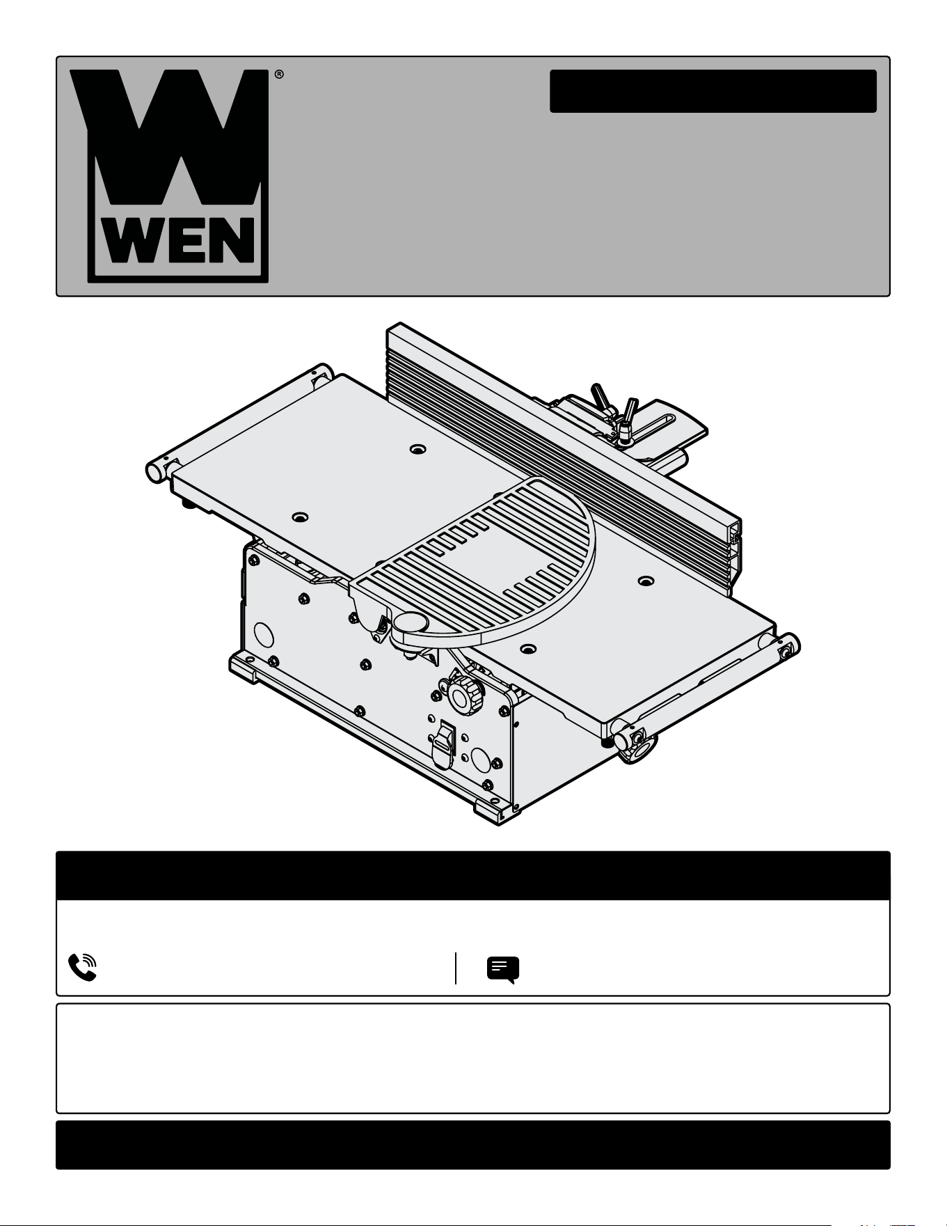
GUIDELINES AND RECOMMENDATIONS FOR EXTENSION CORDS
GROUNDING INSTRUCTIONS
In the event of a malfunction or breakdown, grounding provides the path of least resistance for an electric current
and reduces the risk of electric shock. This tool is equipped with an electric cord that has an equipment grounding
conductor and a grounding plug. The plug MUST be plugged into a matching outlet that is properly installed and
grounded in accordance with ALL local codes and ordinances.
1. Do not modify the plug provided. If it will not fit the outlet, have the proper outlet installed by a licensed electri-
cian.
2. Improper connection of the equipment grounding conductor can result in electric shock. The conductor with the
green insulation (with or without yellow stripes) is the equipment grounding conductor. If repair or replacement of
the electric cord or plug is necessary, DO NOT connect the equipment grounding conductor to a live terminal.
1. Examine extension cord before use. Make sure your extension cord is properly wired and in good condition.
Always replace a damaged extension cord or have it repaired by a qualified person before using it.
2. Do not abuse extension cord. Do not pull on cord to disconnect from receptacle; always disconnect by pulling on
plug. Disconnect the extension cord from the receptacle before disconnecting the product from the extension cord.
Protect your extension cords from sharp objects, excessive heat and damp/wet areas.
3. Use a separate electrical circuit for your tool. This circuit must not be less than a 12-gauge wire and should be
protected with a 15A time-delayed fuse. Before connecting the motor to the power line, make sure the switch is in
the OFF position and the electric current is rated the same as the current stamped on the motor nameplate. Running
at a lower voltage will damage the motor.
When using an extension cord, be sure to use one heavy enough to carry the current your product will draw. An
undersized cord will cause a drop in line voltage resulting in loss of power and overheating. The table below shows
the correct size to be used according to cord length and ampere rating. When in doubt, use a heavier cord. The
smaller the gauge number, the heavier the cord.
Fig. 1
8
AMPERAGE
REQUIRED GAUGE FOR EXTENSION CORDS
25 ft. 50 ft. 100 ft. 150 ft.
12A 14 gauge 12 gauge Not Recommended
9
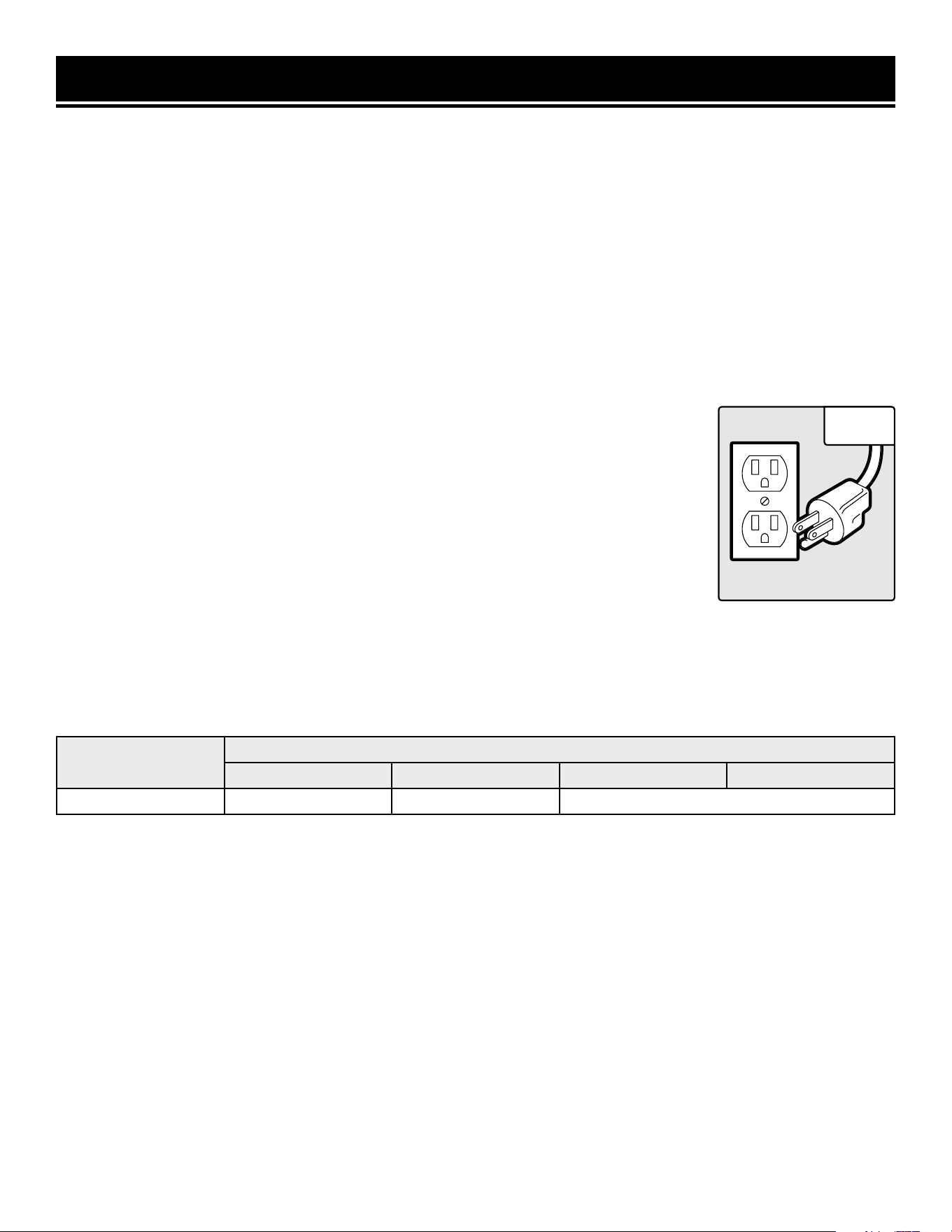
JT1020H Components
UNPACKING
With the help of a friend or trustworthy foe, such as one of your in-laws, carefully remove the jointer from the
packaging and place it on a sturdy, flat surface. Make sure to take out all contents and accessories. Do not discard
the packaging until everything is removed. Check the packing list below to make sure you have all of the parts and
accessories. If any part is missing or broken, please contact customer service at 1-847-429-9263 (M-F 8-5 CST),
or email [email protected].
UNPACKING & PACKING LIST
PACKING LIST
JT1020H & JT1224H Accessories
JT1020H & JT1224H HARDWARE BAG
• Fence Sliding Handle (1)
• M6x16 Socket Head Screw (2)
• Square Nut (2)
• Washer (1)
• 2.5mm Hex Wrench (1)
• 4mm Hex Wrench (1)
• Star Wrench (1)
JT1224H Components
Jointer Jointer
Fence Sliding Bracket (1)
*2.5mm Hex Wrench
Fence (1)
Fence Bracket (1)Dust Port (1)
*4mm Hex Wrench
Dust Port Adapter (1)
*T25 Star Wrench
Push Block (2)
* Included in the hardware bag.
TOOL PURPOSE
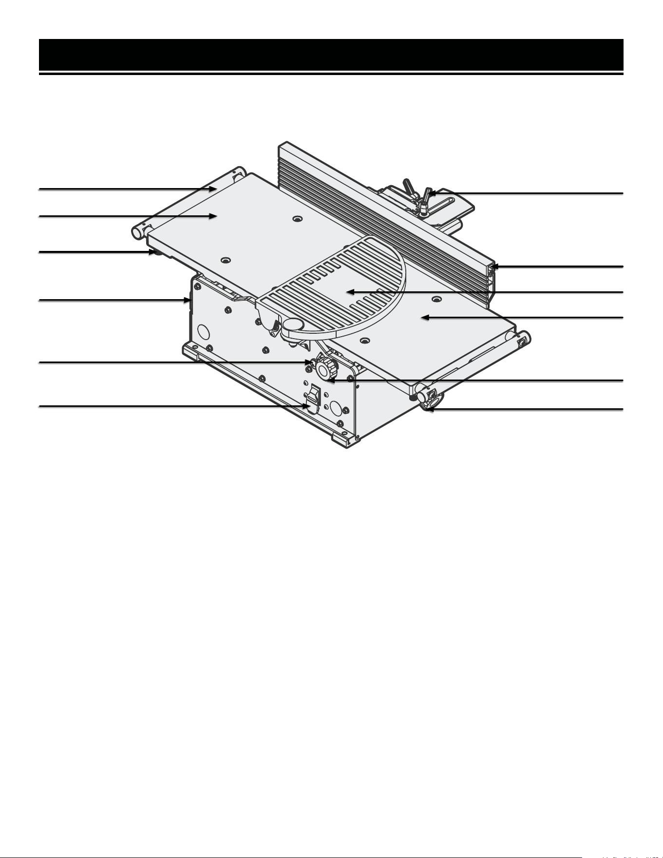
Resurface boards, flatten workpieces, and much more with your WEN Jointer. Refer to the diagram below to be-
come familiarized with the parts and controls of your jointer.
KNOW YOUR JOINTER
10
NOTE: A protective coating of lubricating oil has been applied during assembly to protect against rust. Wipe down
all components thoroughly. Apply a light coat of good-quality paste wax to the table and fence to protect the sur-
faces and make boards slide smoothly.
Fence Support Locking Handle
Fence
Cutterhead Guard
Infeed Table
Depth of Cut Lock Knob
Depth of Cut Adjustment Knob
Extension Arm
Outfeed Table
Dust Port
Depth of Cut Scale
ON / OFF Safety Switch
Arm Lock
11
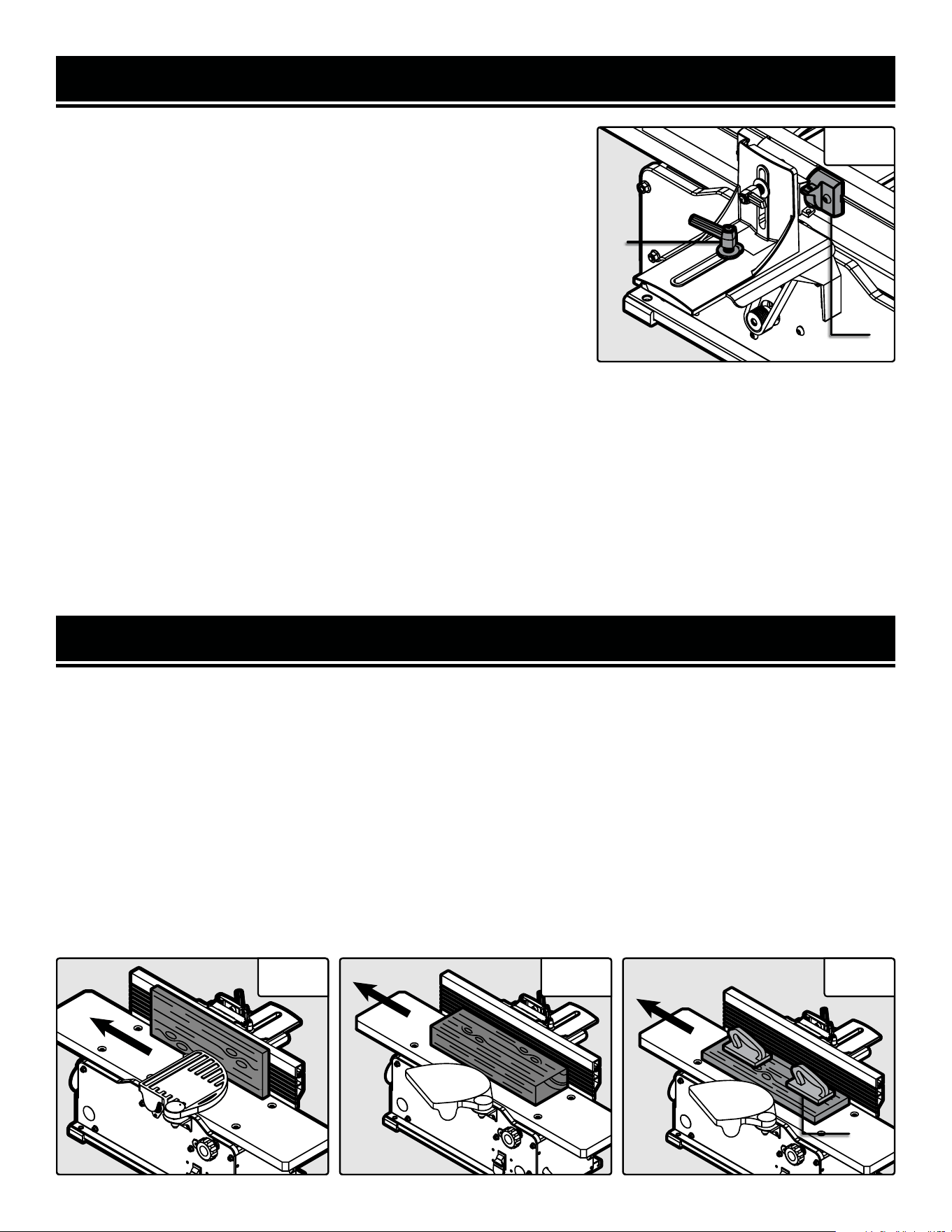
ASSEMBLY & ADJUSTMENTS
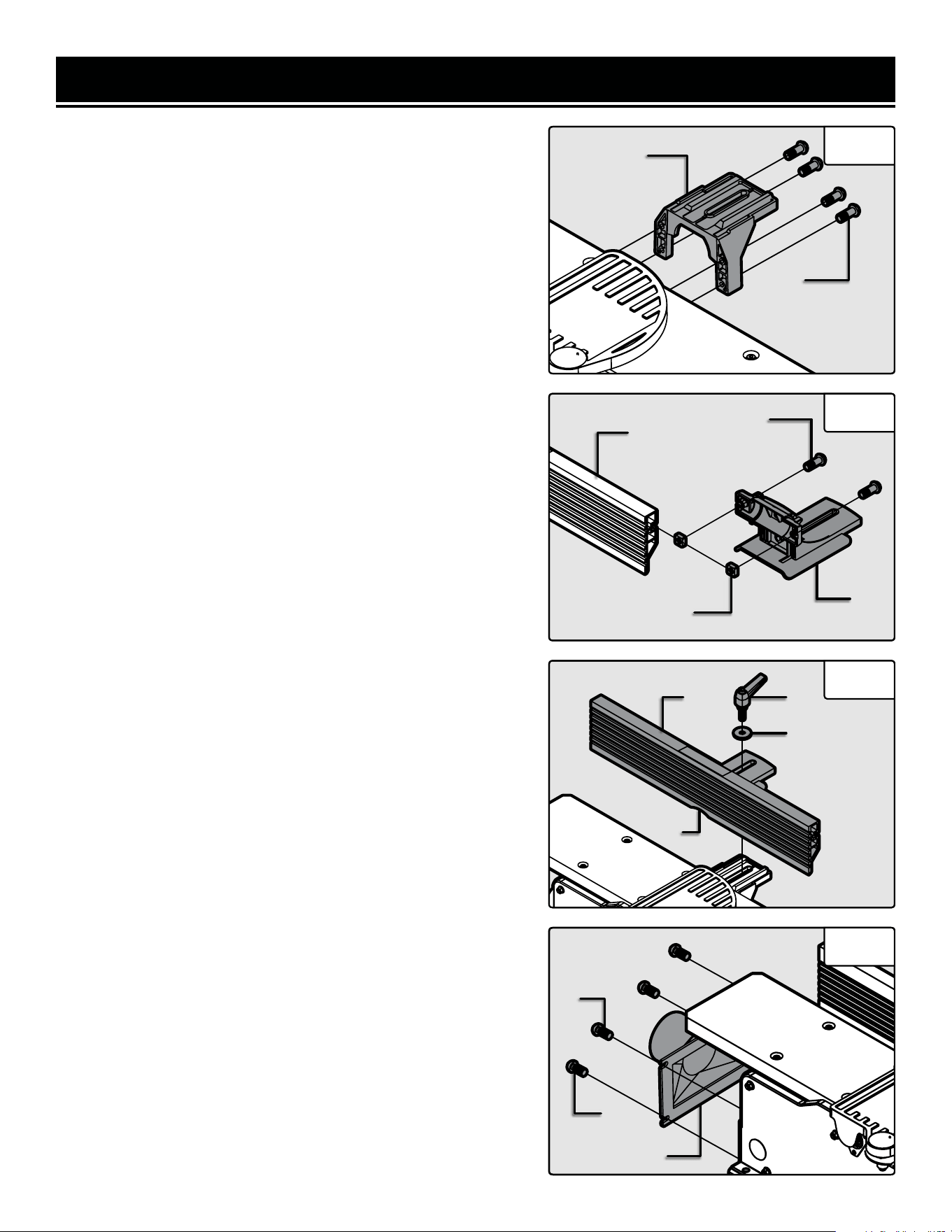
ATTACH THE FENCE
1. Attach the fence support bracket (Fig. 2 - 1) to the jointer with
four socket head bolts (Fig. 2 - 2)
2. Assemble the fence sliding bracket (Fig. 3 - 1) to the fence
(Fig. 3 - 2). Insert the two socket head bolts (Fig. 3 - 3) through
the top of the fence sliding bracket and screw the square nuts
(Fig. 3 - 4) onto the bolts but do not tighten.
3. Slide the square nuts into the grooves on the back of the
fence and position the fence sliding bracket to the middle of the
fence. Tighten the socket head screws (Fig. 3 - 3) once the slid-
ing fence bracket is correctly positioned.
NOTE: Use the fence cutout (Fig 4 - 1) to position the fence slid-
ing bracket in the center of the fence.
4. Place the upper fence assembly (Fig. 4 - 2) on top of the fence
support bracket. Insert the sliding handle (Fig. 4 - 3) through
the flat washer (Fig. 4 - 4), through the sliding bracket, and then
though the support bracket.
5. Hold the rectangular nut under the fence support bracket so
that it fits snugly into the groove with the flat side up. Thread
the sliding handle through the nut until it is tight. and the fence
is secured.
NOTE: The fence sliding handle and fence bevel handle are
spring-loaded and can be re-positioned as need be. Pull out on
the handle, re-position it, and let it spring back in place.
NOTE: The stop limits on the fence bracket have been set at the
factory, but should be checked with an angle gauge to measure
exactly 90° and 135° between the fence and the table top at each
stop limit, respectively. The stop limits can be modified by tight-
ening or loosening the set screws if the angles are not precise.
INSTALL THE DUST CHUTE
1. Remove the two M6x12 screws (Fig. 5 - 1) from the body of
the jointer and the two self tapping screws (Fig. 5 - 2) from the
feet of the jointer.
2. Position the dust port (Fig. 5 - 3) and reinstall all four screws.
Be sure not to over-tighten the screws as doing so might dam-
age the dust port.
NOTE: Your jointer comes with an optional dust port adapter to
allow you to connect to 2-1/2” or 4” hoses.
Fig. 2
1
2
Fig. 3
1
2
3
4
Fig. 4
Fig. 5
1
2 3
4
1
2
3
12
ASSEMBLY & ADJUSTMENTS
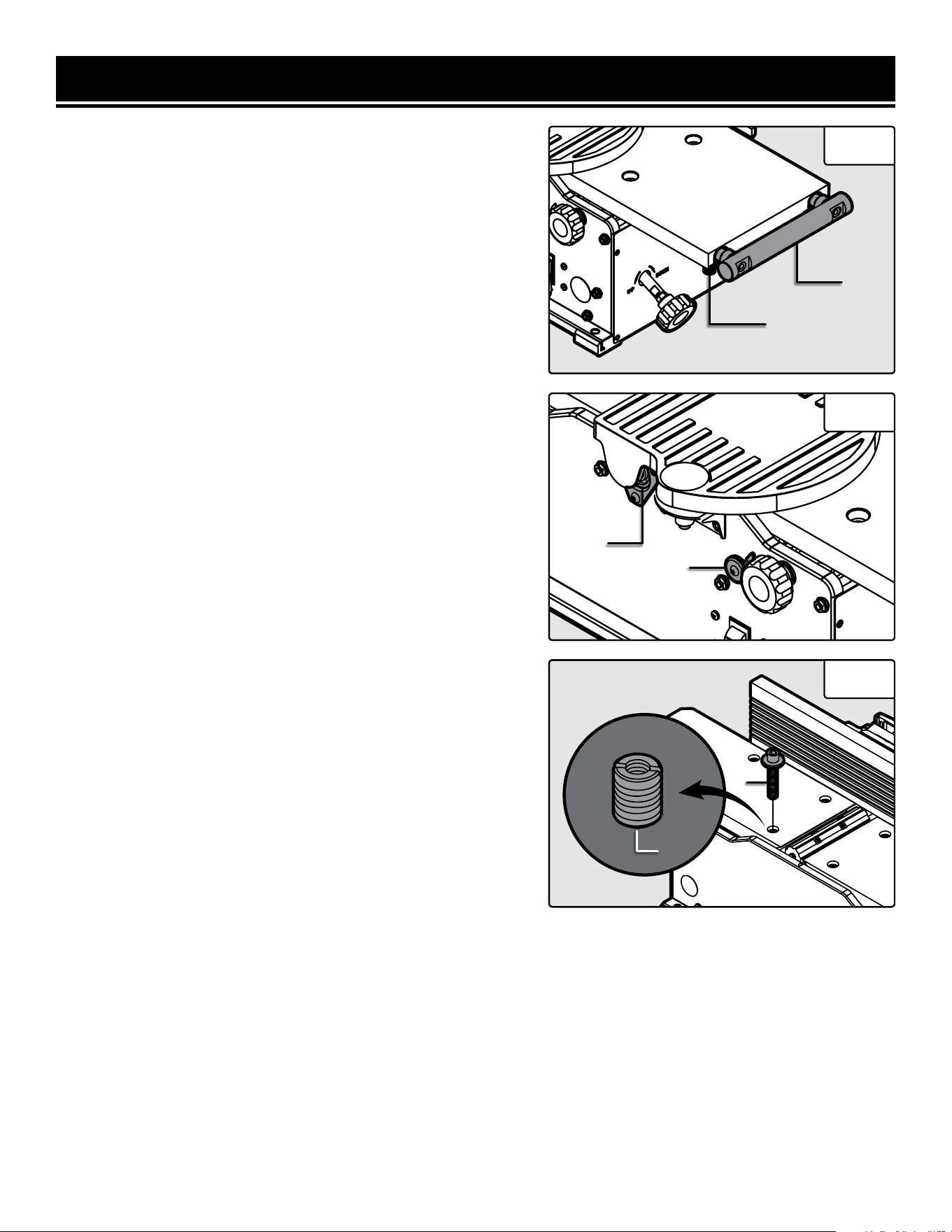
ADJUST THE TABLE SUPPORTS
Your jointer is equipped with extendable table supports (Fig. 6 -
1). To extend the supports, loosen the two knobs (Fig. 6 - 2) on
each side of the support bar and reposition the support to the
desired position. Once the support is in the desired position, re-
tighten the knobs underneath the table.
ADJUST AND LEVEL THE TABLE
The infeed and outfeed table have been pre-set at the factory to
be level and in line with the blades. However, if shipping or use
has caused the table to shift out of level, adjust the tables with
the following steps. Make sure that the unit is unplugged from
any power supply before adjusting the table.
NOTE: This procedure involves close proximity to the helical
blades. To avoid cuts, wear cut-proof or cut-resistant gloves
when performing maintenance work. Remove the gloves before
operating the jointer.
1. Set the depth of cut scale (Fig. 7 - 1) to “0” to bring the infeed
table to its most up most position.
2. Rotate the cutterhead such that some of the blades are at
their highest point. The cutterhead can be safety rotated using
the included 4 mm hex wrench at the front end of the cutterhead
under the blade guard flange (Fig. 7 - 2).
3. Use a long metal straight edge to check the height of the
outfeed table. Place the straight edge over the outfeed table and
the cutterhead blades. Check that the blades barely touch the
straight edge at both the front and back of the cutterhead. You
will need to rotate the cutterhead to check both the front and
back alignment of the table.
4. If the blades do not touch the straight edge or drastically hit
the straight edge, the outfeed table will need to be adjusted.
a. Use the included 4mm hex wrench to loosen and remove
the bolts (Fig. 8 - 1) countersunk in the table. There are four
in the infeed table and four in the outfeed table. Remove the
washers as well to access the slotted screws (Fig. 8 - 2) un-
derneath.
Fig. 6
1
2
Fig. 7
1
b. Use a flat head screwdriver to adjust the slotted screw. Turning the screw clockwise will lift the table up and
turning counterclockwise will lower the table. Adjustments to the screw should be minimal, with only a 1/20th
turn before rechecking the table’s position with the straight edge.
c. Once the table is level and at the correct height, reinstall the washer and bolt to secure the table.
5. Once the outfeed table is set at the correct height, follow the steps above to ensure that the infeed table is at the
correct height.
Directions continue on the next page.
Fig. 8
2
1
2
13
ASSEMBLY & ADJUSTMENTS
WARNING! Do not plug in or turn on the tool until it is fully assembled according to these instructions.
Failure to follow the safety instructions may result in serious personal injury.
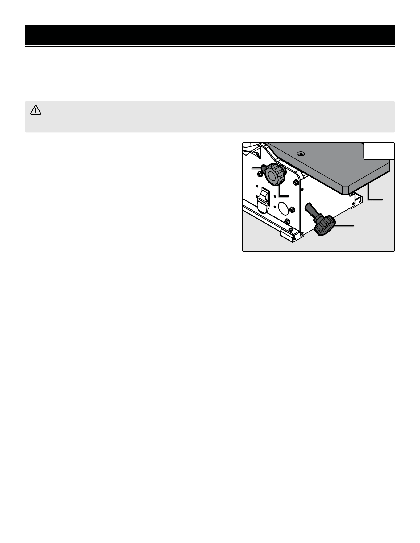
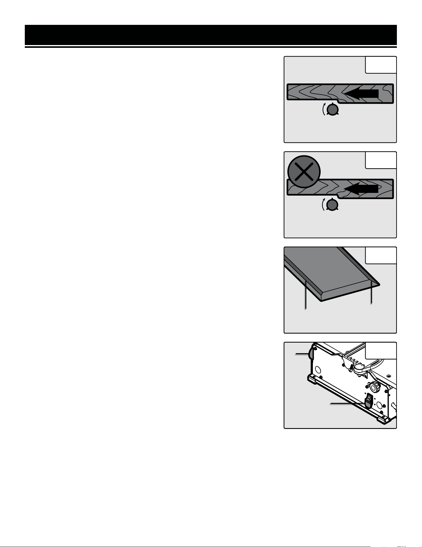
ADJUST THE DEPTH OF CUT
The depth of cut is adjusted by the relative positioning of the
infeed table with respect to the cutterhead. The infeed table (Fig.
9 - 1) can be raised or lowered using the infeed adjustment knob
(Fig. 9 - 2). Turning the knob counterclockwise will raise the
infeed table, causing less wood to be removed from the work-
piece, as seen on the depth of cut scale (Fig. 9 - 3). Turning the
hand wheel clockwise will lower the infeed table, causing more
wood to be removed from the workpiece. Always make sure that
the front lock knob (Fig. 9 - 4) is loosened before changing the
depth of cut and tightened after the desired change has been
made so that the depth of cut does not differ between cuts. Do
not make jointing cuts deeper than 1/8 of an inch.
NOTE: For a smooth finish, it is recommended to do multiple passes at a lower depth. We recommend using a depth
of 1/32”. Always using a depth of 1/8” will shorten the lifespan of your jointer and give you a rougher finish.
BEVEL THE FENCE
NOTE: The fence can easily be set to 0° and 45° using the limit stops (Fig. 10 - 2) on the fence. However, it is always
advisable to check the angles with a piece of scrap wood before jointing your final workpiece. Adjust the set screws
that act as limit stops if they are not exact or have moved from shipping or use.
The fence can be positioned to joint the wood at any angle from 0° to 45°.
1. Before adjusting the fence’s angle, make sure that the unit is unplugged and the power switch is in the OFF posi-
tion.
2. Turn the fence bevel handle counterclockwise to loosen it. If you find it necessary to reposition the handle in order
to loosen it, pull it outwards, turn the handle to the new position, and release it.
3. Manually tilt the fence to desired angle; use an angle gauge block (not included) to see the current angle.
4. Once the desired angle has been achieved, tighten the bevel handle.
ADJUST AND LEVEL THE TABLE (CONT.)
6. When both the infeed and outfeed tables are aligned with the blades, lay the straightedge across the infeed and
outfeed tables to ensure that they are level. If the tables are not perfectly aligned, tune the outfeed table to the infeed
table using step 4 above to adjust the level of the table.
Fig. 9
1
2
4
3
ASSEMBLY & ADJUSTMENTS
14
MOVE THE FENCE
1. Before adjusting the fence’s position, make sure that the unit is un-
plugged and the power switch is in the OFF position.
2. Loosen the fence sliding handle (Fig. 10 - 1).
3. Slide the fence to the desired position. The fence can be positioned
over the blade so that only the desired width of the blade is exposed.
Make sure the exposed width matches that of the workpiece.
4. Tighten the fence sliding handle so that the fence is secure.
AVOID DAMAGE TO BLADES
Fig. 10
1
FEED A WORKPIECE
Feed rate refers to the rate at which wood is passed over the blades. An even feed rate produces a uniform finish.
1. Hold the work piece firmly down on the feed table and against the fence.
2. Feed the work piece at an even rate over the cutterhead. Any hesitation or stopping will cause a “step” to be cut
in the work piece. See Figs. 11 - 13 for different feeding methods.
3. As your trailing hand passes over the cutterhead, remove your leading hand and place behind your trailing hand
and repeat until the entire length of the workpiece has been cut. Always use a push block or push stick (Fig. 13 - 1),
but it is especially critical to help hold and feed the workpiece when jointing wood that is narrower than 3 inches or
thinner than 3 inches.
Directions continue on the next page.
Jointers are a precision woodworking machine and should be used on quality lumber only. Do not join dirty boards;
dirt and small stones are abrasive and will wear out the blades.
For proper operation, attach a dust collection system to the dust port, on the left of the jointer. Attaching a dust col-
lection system is very important when taking deeper cuts to prevent wood chips clogging the unit.
Remove nails and staples. Only use the jointer to cut wood. Avoid knots. Heavily cross-grained wood makes knots
hard. Knots can come loose and jam blades.
Assess the value of badly warped boards. You may be tempted to take a deep cut to square the boards quickly, when
a better approach is to use several passes with a shallower cut.
Fig. 11 Fig. 12 Fig. 13
1
OPERATION
2
15
OPERATION
Fig. 14
Fig. 15
FEED
Rotation
Against the Grain
FEED
Rotation
With the Grain
4. Cut with the grain whenever possible (Fig. 14). Do not feed against the end
grain (Fig. 15), otherwise the workpiece may split and shatter. If the nature of
the workpiece requires you to joint against the grain, take extremely light cuts
and feed slowly. When using long work pieces, use extra supports at both
ends of the jointer.
BEVEL AND CHAMFER
The fence on the jointer is adjustable from 0° to 45°. Adjust the fence to the
desired angle and tighten the bevel handle.
Beveling refers to cutting the entire edge of a board at an angle. Beveling may
require several passes due to the depth of the cut needed. See Fig. 16.
Chamfering refers to removing only the corner of the edge of a board. Nor-
mally a chamfer is made in one pass; so a 1/16-inch deep cut is made. See
Fig. 16.
ATTACH A VACUUM HOSE
A 2-1/2” (or 4” with the dust port adapter) dust collection hose can be at-
tached to the dust port underneath the outfeed table. The jointer will perform
properly at all depths of cuts up to 1/8” when using a dust collection system.
NOTE: Make sure the jointer and dust collection system are on separate elec-
trical circuits. This will prevent circuits from overloading.
1. Make sure the switch is in the OFF position and that the cord is unplugged
before attaching the vacuum hose.
2. Attach the dust collection hose to the dust port (Fig. 17 - 1).
3. Turn the dust collection system ON before starting the jointer. Periodically
replace and empty the bag in the collection system according to the manufac-
turer’s instructions.
ON/OFF SWITCH
The ON/OFF switch (Fig. 17 - 2) is located on the front of the jointer.
1. To turn the jointer ON, move the switch to the up position.
2. To turn the jointer OFF, move the switch to the down position.
3. Remove the yellow tab to engage the child-safety lock and prevent un-
wanted start-ups.
Fig. 16
Chamfer
Edge
Bevel
Edge
Fig. 17
1
2
MAINTENANCE
16
ROUTINE INSPECTION
Before each use, inspect the general condition of the tool. If any of the following conditions exist, do not use until
parts are replaced or the jointer is properly repaired.
Check for:
• Loose hardware or improper mounting,
• Misalignment or binding of moving parts,
• Damaged cord/electrical wiring,
• Worn or damaged blades,
• Cracked or broken parts, and
• Any other condition that may affect its safe operation
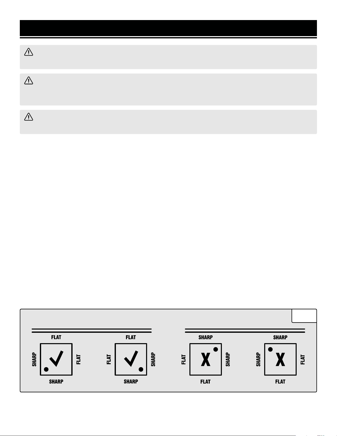
CHECK FOR WORN BLADES
The condition of blades will affect the precision of the cuts. Observe the quality of the cut that the jointer produces
to check the condition of the blades. Dull blades will tear wood fibers and produce fuzzy surfaces. Raised grain will
occur when dull blades pound on wood that has varying density. Raised edges will also be produced where the
blades have been nicked. Blades on this jointer should always replaced as a matched set. Keeping a spare set of
blades on hand is recommended. Replacement blades (part no. BP510H) can be ordered from wenproducts.com.
NOTE: Blades are only sharp on two edges. Make sure that the edge facing the infeed table has a sharp cutting edge.
Refer to Fig. 18 for more detail.
WARNING! To avoid accidents, turn OFF and unplug the tool from the electrical outlet before cleaning, ad-
justing, or performing any maintenance or lubrication work.
WARNING! Any attempt to repair or replace electrical parts on this tool may be hazardous. Servicing of the
tool must be performed by a qualified technician. When servicing, use only identical WEN replacement parts.
Use of other parts may be hazardous or induce product failure.
WARNING! To avoid cuts, wear cut-proof or cut-resistant gloves when performing maintenance work. Re-
move the gloves before operating the jointer.
CUTTERHEAD
Fig. 18

17
MAINTENANCE
WARNING! To avoid cuts, wear cut-proof or cut-resistant gloves when performing maintenance work on the
blades. Remove the gloves before operating the jointer.
REPLACING OR ROTATING BLADES
Your jointer is equipped with a helical cutting head consisting of either 20 or 24 blades, depending on the model.
Each blade is indexed with a small dot in the corner to denote the two sharp sides of the blade. Once a side of the
blade is dull or nicked, use the star head wrench to remove the retaining screw to rotate or replace the blade. The
blades are machined to be properly positioned once the retaining screw is tightened, but make sure that all dust and
debris is cleared away to help the blade be seated properly. Make sure that the unit is unplugged from the power
supply before changing any blades.
NOTE: To avoid cuts, wear cut-proof or cut-resistant gloves when performing maintenance work. Remove the
gloves before operating the jointer.
1. Insert the 4 mm hex wrench at the front of the cutterhead under the blade guard flange to hold the cutterhead
still while working with the blades.
2. Use the T25 star wrench to remove the retaining screw and the blade from the cutterhead.
3. While the blade is removed, check the cutterhead for any resin build up or dust that is stuck around the blade
location. Use a brush (such as an old toothbrush) and suitable solvents to clean the cutterhead so that the blade will
be seated properly.
4. Rotate or replace the blade to the desired position. Be sure to note the position of the small dot to ensure the blade
is being installed with a new sharp edge (Fig. 18).
5. Tighten the retaining screw back on the cutterhead to hold the blade in place. Do not overtighten the retaining
screw as this might damage the blade. Make sure that the screw is only tightened with a torque of about 50 inch-lbs.
CLEANING & STORAGE
1. After every operation, use a vacuum to remove dust and chips from the tool surfaces, motor housing and work
area. Keep the ventilation openings free from dust and debris to prevent the motor from overheating.
2. Wipe the tool surfaces clean with a soft cloth or brush. Make sure water does not get into the tool.
3. Lubricate the table bracket and locking knobs if they become difficult to use.

18
PROBLEM CAUSE SOLUTION
Motor does not start.
Jointer is not plugged in. Plug jointer in.
Wrong choice of extension cord. Choose proper size of extension cord.
Defective switch.
Contact customer service at 1-847-
429-9263, M - F, 8 - 5 CST.
Defective motor.
Contact customer service at 1-847-
429-9263, M - F, 8 - 5 CST.
Worn carbon brushes. Replace carbon brushes.
Low line voltage. Correct low line voltage condition.
Motor starts slowly or fails to
come to full speed.
Defective motor windings.
Contact customer service at 1-847-
429-9263, M - F, 8 - 5 CST.
Clogged wood chips.
Make a shallower cut and attach a
dust collection device to the dust port.
Inspect the chip blower assembly and
the fan belt.
Motor is running too hot.
Motor overloaded.
Reduce the load on the motor (take
shallower cuts).
Restricted air circulation due to dust
accumulation.
Clean out the dust and restore normal
air circulation.
Snipe
(gouging at end of boards)
Dull blades. Replace or sharpen blades.
Inadequate support of long boards. Support long boards.
Uneven feed.
Feed the workpiece at a consistent
rate.
Poor dust extraction.
1) Dust extraction manifold is clogged.
2) The fan belt is bad.
1) Clean inside of jointer and manifold.
2) Replace the belt.
The cutterhead is not
spinning.
Bad drive belt. Replace drive belt.
NOTE: Carbon brush life depends on the amount of load being taken on by the motor. Regularly
inspect the brushes after 50 hours of use.
TROUBLESHOOTING GUIDE
WARNING! Stop using the tool immediately if any of the following problems occur. Repairs and replace-
ments should only be performed by an authorized technician. For any questions, please contact our customer
service at 1-847-429-9263, M-F 8-5 CST or email us at [email protected].

19
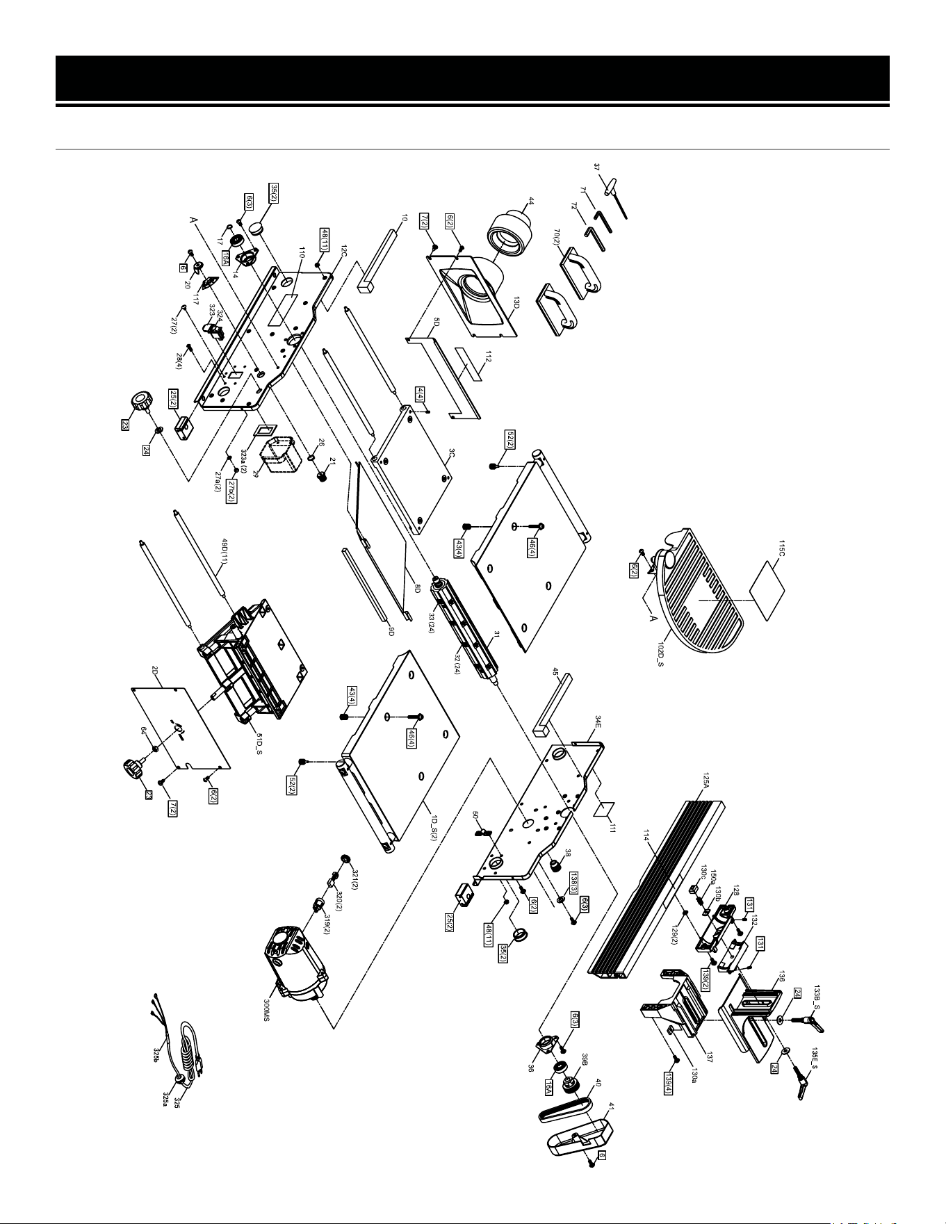
EXPLODED VIEW & PARTS LIST
JT1020H
6(3)6(3)
44
48(11)
17
112
138(3)
70(2)
4(4)
50
49C(11)
35(2)
35(2)
34B
28(4)
27b(2)
27a(2)
27(2)
26
25(2)
25(2)
24
23
21
13C
12C
9C
7(2)
6(2)
6(3)
6(2)
5C
3C
8C
31_S
33(2 0)
117
20
6
14_S
41
40
39a
36_S
6(3)
6
110
22
99
3322
33
aa((
22
))
32(2 0)
1C_S
(2)
52(2)
52(2)
102C_S
115C
51C_S
64
23
2C
43(4)
43(4)
46(4)
46(4)
6(2)
7(2)
48(11)
300MS
38
324
323
125A
114
132
129(2)
128
131
131
139(4)
137
136
130a
24
24
139(2)
130b
150a
130c
6(2)
133B_S
135E_S
321(2)
320(2)
319(2)
325b
325a
325
37
71
72

EXPLODED VIEW & PARTS LIST
20
No. Part No. Description Qty.
1C_S
JT1020H-
001ASM
Table Assembly 2
1C JT1020H-001 Table 2
2C JT1020H-002 Right Cover 1
3C JT1020H-003 Outfeed Support 1
4 JT630H-004 Set Screw M6x8 8
5C JT1020H-005 Left Cover 1
6 JT630H-006
Round Head Allen
Screw M6x12
19
7 JT630H-007
Round Head
Self-Tapping Allen
Screw
4
8C JT1020H-008 Dust Chute 1
9C JT1020H-009 Foam Seal 1
12C JT1020H-012 Front Frame 11
13C JT1020H-013 Dust Port 1
14_S JT630H-014ASM
Bearing Retainer
Assy.
1
17 JT1020H-017
External Retaining
Ring
1
20 JT630H-020 Pointer 1
21 JT630H-021 Gear 1
23 JT630H-023 Lock Knob M8 2
24 JT630H-024 8mm Flat Washer 3
25 JT630H-025 Foot 4
26 JT630H-026
External Retaining
Ring
5
27 JT630H-027 Screw M5-0.8x8 2
27a JT630H-027A Lock Washer, 5mm 2
27b JT630H-027B Hex Nut M5 6
28 JT630H-028 Screw M5-0.8x25 4
29 JT1020H-029 Switch Box 1
30_S
JT1020H-
030ASM
Spiral Cutterhead
Assembly
1
32 BP510H HSS Blade 20
33 JT630H-163
Star Head Cap Screw,
M5x15
20
34B JT1020H-034 Rear Frame 1
35 JT630H-035 Hole Plug 4
36_S JT630H-036ASM
Bearing Retainer
Assembly
1
No. Part No. Description Qty.
37 JT630H-166 Torx Wrench, T25 1
38 JT1020H-038 Motor Pulley 1
39a JT1020H-039 Cutterhead Pulley 1
40 JT630H-040 Grooved Belt, 125J-5 1
41 JT630H-041 Belt Guard 1
43 JT1020H-043
Adjustment Screw,
M12-1.25x14
8
44 JT1020H-044 Dust Port Adapter 1
46 JT1020H-046
Hex Socket Screw,
M6x30
8
48 JT630H-048 Flange Nut 22
49C JT1020H-049 Support Rod 11
50 JT630H-050 Cord Clamp 1
51C_S
JT1020H-
051ASM
Infeed Support
Assembly
1
52 JT1020H-052
Extension Rod Lock
Knob
4
64 JT630H-064 M8 Hex Nut 1
70 JT630H-070 Jointer Push Block 2
71 JT630H-071 2.5 mm Hex Wrench 1
72 JT630H-072 4 mm Hex Wrench 1
102C_S
JT1020H-
102ASM
Cutterhead Guard
Assembly
1
110 JT1020H-110 Logo Label 1
111 JT1020H-111 Warning Label 1 1
112 JT1020H-112 Warning Label 2 1
114 JT1020H-114 Warning Label 3 1
115C JT1020H-115
Cutterhead Warning
Label
1
117 JT1020H-117 Scale Label 1
125A
JT1020H-
125ASM
Fence Assembly 1
128 JT630H-128 Bevel Bracket 1
129 JT630H-129 Square Nut 2
130a JT1020H-130a
Bracket Rectangular
Nut
1
130b JT1020H-130b
Fence Rectangular
Nut 1
1
130c JT1020H-130c
Fence Rectangular
Nut 2
1
JT1020H

21
No. Part No. Description Qty.
131 JT630H-131 Set Screw M5-0.8x8 2
132 JT630H-132 Intermediate Bracket 1
133B_S
JT1020H-
133ASM
Fence Locking Knob
Assembly
1
135E_S
JT1020H-
135ASM
Fence Bevel Knob
Assembly
1
136 JT630H-136 Fence Slide Bracket 1
137 JT630H-137 Fence Bracket 1
138 JT630H-138 Flat Washer 3
139 JT630H-139 Screw M6x16 6
EXPLODED VIEW & PARTS LIST
No. Part No. Description Qty.
150a JT1020H-150 Spring 1
300MS
JT1020H-
300ASM
Motor Assembly 1
319 JT1020H-319 Carbon Brush Holder 2
320 JT1020H-320 Carbon Brush 2
321 JT1020H-321 Carbon Brush Cap 2
323 JT630H-323 Switch 1
323a JT630H-323A Switch Cover 1
324 JT630H-324 Switch Key 1
325 JT1020H-325 Power Cord 1
JT1020H
EXPLODED VIEW & PARTS LIST
JT1224H
22

EXPLODED VIEW & PARTS LIST
JT1224H
No. Part No. Description Qty.
1D_S
JT1224H-
001ASM
Table Assembly 2
2D JT1224H-002 Right Cover 1
3C JT1020H-003 Outfeed Support 1
4 JT630H-004 Set Screw M6x8 8
5D JT1224H-005 Left Cover 1
6 JT630H-006
Round Head Allen
Screw M6x12
19
7 JT630H-007
Round Head
Self-Tapping Allen
Screw
4
8D JT1224H-008 Dust Chute 1
9D JT1224H-009 Foam Seal 1
10 JT1224H-010 Foam Seal 1
12C JT1020H-012 Front Frame 1
13D JT1224H-013 Dust Port 1
14_S
JT630H-
014ASM
Bearing Retainer As-
sembly
1
17 JT1020H-017
External Retaining
Ring
1
20 JT630H-020 Pointer 1
21 JT630H-021 Gear 1
23 JT630H-023 Lock Knob M8 2
24 JT630H-024 8mm Flat Washer 3
25 JT630H-025 Foot 4
26 JT630H-026
External Retaining
Ring
1
27 JT630H-027 Screw M5-0.8x8 2
27a JT630H-027A Lock Washer, 5mm 2
27b JT630H-027B Hex Nut M5 6
28 JT630H-028 Screw M5-0.8x25 4
29 JT1020H-029 Switch Box 1
31
JT1224H-
030ASM
Spiral Cutterhead As-
sembly
1
32 BP510H HSS Blade 24
33 JT630H-163
Star Head Cap Screw,
M5x15
24
34E JT1224H-034 Rear Frame 1
35 JT630H-035 Hole Plug 4
36_S
JT630H-
036ASM
Bearing Retainer As-
sembly
1
No. Part No. Description Qty.
37 JT630H-166 Torx Wrench, T25 1
38 JT1020H-038 Motor Pulley 1
39B JT1224H-039 Cutterhead Pulley 1
40 JT630H-040
Grooved Belt,
125J-5
1
41 JT630H-041 Belt Guard 1
43 JT1020H-043
Adjustment Screw,
M12-1.25x14
8
44 JT1020H-044 Dust Port Adapter 1
46 JT1020H-046
Hex Socket Screw,
M6x30
8
48 JT630H-048 Flange Nut 22
49D JT1224H-049 Support Rod 11
50 JT630H-050 Cord Clamp 1
51D_S
JT1224H-
051ASM
Infeed Support
Assembly
1
52 JT1020H-052
Extension Rod Lock
Knob
4
64 JT630H-064 M8 Hex Nut 1
70 JT630H-070 Jointer Push Block 2
71 JT630H-071 2.5 mm Hex Wrench 1
72 JT630H-072 4 mm Hex Wrench 1
102D_S
JT1224H-
102ASM
Cutterhead Guard As-
sembly
1
110 JT1020H-110 Logo Label 1
112 JT1020H-112 Warning Label 1 1
114 JT1020H-114 Warning Label 2 1
115C JT1020H-115
Cutterhead Warning
Label
1
117 JT1020H-117 Scale Label 1
125A
JT1020H-
125ASM
Fence Assembly 1
128 JT630H-128 Bevel Bracket 1
129 JT630H-129 Square Nut 2
130a JT1020H-130a
Bracket Rectangular
Nut
1
130b JT1020H-130b
Fence Rectangular
Nut 1
1
130c JT1020H-130c
Fence Rectangular
Nut 2
1
131 JT630H-131 Set Screw M5-0.8x8 2
23

24
No. Part No. Description Qty.
132 JT630H-132
Intermediate
Bracket
1
133B_S
JT1020H-
133ASM
Fence Locking Knob
Assembly
1
135E_S
JT1020H-
135ASM
Fence Bevel Knob As-
sembly
1
136 JT630H-136 Fence Slide Bracket 1
137 JT630H-137 Fence Bracket 1
138 JT630H-138 Flat Washer 3
139 JT630H-139 Screw M6x16 6
No. Part No. Description Qty.
150a JT1020H-150a Spring 1
300MS
JT1020H-
300ASM
Motor Assembly 1
319 JT1020H-319 Carbon Brush Holder 2
320 JT1020H-320 Carbon Brush 2
321 JT1020H-321 Carbon Brush Cap 2
323 JT630H-323 Switch 1
323a JT630H-323A Switch Cover 1
324 JT630H-324 Switch Key 1
325 JT1020H-325 Power Cord 1
EXPLODED VIEW & PARTS LIST
JT1224H

WARRANTY STATEMENT
25
WEN Products is committed to building tools that are dependable for years. Our warranties are consistent with this
commitment and our dedication to qualit
y.
LIMITED WARRANTY OF WEN PRODUCTS FOR HOME USE
GRE
AT LAKES TECHNOLOGIES, LLC (“Seller”) warrants to the original purchaser only, that all WEN
consumer
power tools will be free from defects in material or workmanship during personal use for a period of two (2) years
used
for professional or commercial use. Purchaser has 30 days from the date of purchase to report missing or
damaged parts.
SELLER’S
SOLE OBLIGATION AND YOUR EXCLUSIVE REMEDY under this Limited Warranty and, to the extent per-
mitted
by law, any warranty or condition implied by law, shall be the replacement of parts, without charge, which a
re
defective
in material or workmanship and which have not been subjected to misuse, alteration, careless handling,
misrepair
, abuse, neglect, normal wear and tear,
improper maintenance, or other conditions adversely affecting the
Product
or the component of the Product, whether by accident or intentionally, by persons other than Seller. To
make
a claim under this Limited Warranty, you must make sure to keep a copy of your proof of purchase that
clearly
-
dor
of Great Lakes Technologies, LLC. Purchasing through third party vendors, including but not limited to garage
sales,
pawn shops, resale shops, or any other secondhand merchant, voids the warranty included with this
product.
Contact [email protected] or 1-847-429-9263 with the following information to make arrangements:
your
shipping address, phone number, serial number, required part numbers, and proof of purchase. Damaged
or
defective parts and products may need to be sent to WEN before the replacements can be shipped out.
-
turning
a product for warranty service, the shipping charges must be prepaid by the purchaser. The product
must
be
shipped in its original container (or an equivalent), properly packed to withstand the hazards of shipment. The
product
must be fully insured with a copy of the proof of purchase enclosed. There must also be a description of
the
will be returned and shipped back to the pur
chaser at no charge for addresses within the contiguous United States.
THIS
LIMITED WARRANTY DOES NOT APPLY TO ITEMS THAT WEAR OUT FROM REGULAR USAGE OVER TIME,
INCLUDING
BELTS, BRUSHES, BLADES, BATTERIES, ETC. ANY IMPLIED WARRANTIES SHALL BE LIMITED IN
DUR
ATION TO TWO (2) YEARS FROM DATE OF PURCHASE. SOME STATES IN THE U.S. AND SOME CANADIAN
PROVINCES
DO NOT ALLOW LIMITATIONS ON HOW LONG AN IMPLIED WARRANTY LASTS, SO THE ABOVE LIMI-
TAT
ION MAY NOT APPLY TO YOU.
IN
NO EVENT SHALL SELLER BE LIABLE FOR ANY INCIDENTAL OR CONSEQUENTIAL DAMAGES (INCLUDING
BUT
NOT LIMITED TO LIABILITY FOR LOSS OF PROFITS) ARISING FROM THE SALE OR USE OF THIS PRODUCT.
SOME ST
ATES IN THE U.S. AND SOME CANADIAN PROVINCES DO NOT ALLOW THE EXCLUSION OR LIMITAT
ION
OF
INCIDENTAL OR CONSEQUENTIAL DAMAGES, SO THE ABOVE LIMITATION OR EXCLUSION MAY NOT APPLY
TO YOU.
THIS
LIMITED WARRANTY GIVES YOU SPECIFIC LEGAL RIGHTS, AND YOU MAY ALSO HAVE OTHER RIGHTS
WHICH
VARY FROM STATE TO STATE IN THE U.S., PROVINCE TO PROVINCE IN CANADA AND FROM COUNTRY
TO COUNT
RY.
THIS
LIMITED WARRANTY APPLIES ONLY TO ITEMS SOLD WITHIN THE UNITED STATES OF AMERICA, CANA-
DA
AND THE COMMONWEALTH OF PUERTO RICO. FOR WARRANTY COVERAGE WITHIN OTHER
COUNTRIES,
CONT
ACT THE WEN CUSTOMER SUPPORT LINE. FOR WARRANTY PARTS OR PRODUCTS REPAIRED UNDER
W
ARRANTY SHIPPING TO ADDRESSES OUTSIDE OF THE CONTIGUOUS UNITED STATES, ADDITIONAL
SHIPPING
CHARGES MAY APPLY.

26
NOTES

27
NOTES

V. 2024.06.27
THANKS FOR
REMEMBERING