INSTALLATION/OWNER'S MANUAL
AM/FM Weatherproof Receiver with Bluetooth and Fixed Face
MTR14G

2
MTR14G INSTALLATION
Preparation
Please read entire manual before installation.
Before You Start
• Disconnect negative battery terminal. Consult a qualified technician for
instructions.
• Avoid installing the unit where it would be subject to high temperatures, such
as from direct sunlight, or where it would be subject to dust, dirt or excessive
vibration.
Getting Started
•Insert the supplied keys into the slots as shown, and slide the unit out of the
mounting sleeve.
• Install mounting sleeve into opening, bending tabs to secure.
• Connect wiring harness and antenna. Consult a qualified technician if you are
unsure.
• Certain vehicles may require an installation kit and/or wiring
harness adapter (sold separately).
• Test for correct operation and slide into mounting sleeve to secure.
• Snap trim ring into plac
e.
TYPICAL
FRONT-LOAD
DIN MOUNTING
METHOD
3
MTR14G INSTALLATION
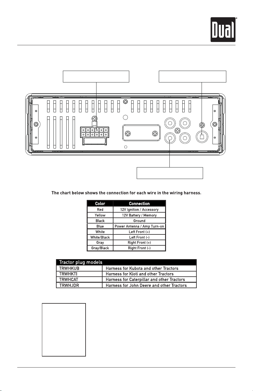
Wiring Diagram
FUSE
When replacing the
fuse, make sure new
fuse is the correct type
and amperage. Using
an incorrect fuse could
damage the radio.
USE 10A ATC
REPLACEMENT FUSE ONLY
RCA Preamp Outputs
AM/FM Antenna Input
Power Harness Input
4
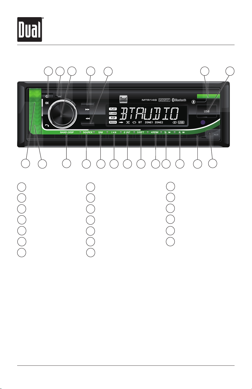
Control Locations
Preset 1 / Play/Pause
Dimmer
Source
Band/Display
Bluetooth Talk
Mute
Power
Microphone
Volume / Audio
Tune / Track Up
Tune / Track Down
Voice Assist
USB Port
1
11
2
12
3
13
4
14
5
15
6
16
7
17
8
18
9
10
Auxiliary Input
Reset
Preset 6 / Folder Up
Preset 5 / Folder Down
Preset 4 / Random
Preset 3 / Repeat
Preset 2 / Intro
1 3 6
8
7
9
5
4
18
2
19
20
19
20
MTR14G INSTALLATION
17
15 14 13 12 11 10
16

5
Press the button to turn the unit on. Press again to
turn the unit off.
Press SOURCE to select between Radio, USB, Auxiliary
Input and Bluetooth. Sources of operation are shown in
the display.
Adjust volume using the volume knob.
Press to silence the audio. Press again to resume
listening at the previously selected volume.
Press DISP to toggle between various displayed
information.
Press DIM to select the dimmer level: DIM HI/DIM MED/
DIM LOW.
Insert a 3.5mm cable in the unit's front AUX port.
With the unit on, press BAND/DISP to display clock time.
Press and hold BAND/DISP until the hours begins to
flash, then release.
Rotate the volume knob left or right to adjust the hours,
then press BAND/DISP. When the minutes begins to
flash, rotate the volume knob left or right to adjust the
minutes.
Press BAND/DISP momentarily to save the selected time.
Press the RESET button to reset the unit back to the
factory settings if abnormal operation occurs. The reset
button is located on the front panel.
Press the volume knob momentarily to select between
audio functions.
Press and hold the volume knob for more than two
seconds to select between the menu functions.
Rotate the volume knob left/right to adjust or activate
the desired function/audio.
Power On/Off
Changing Modes
Volume
Mute
Display
Dimmer
Auxiliary Input
Setting the Clock
Reset
Audio / Menu
General Operation
MTR14G INSTALLATION
Press and hold the volume knob to select the menu,
ZONE1 and ZONE2. Rotate the volume Knob right to adjust
ZONE OFF, ZONE1 ON, ZONE2 ON, and ZONE1 and 2 on.
(Included IR remote can also control them.)
Audio Zone
6
AM/FM Tuner Operation
Seek Tuning
Manual Tuning
Band
Storing Presets
Recalling Presets
Auto Store
Preset Scan Stations
Press and hold TUNE or TUNE for two seconds
to auto seek to the previous or next strong station.
Press TUNE or TUNE momentarily to change
radio frequency up or down one step at a time. Press
and hold TUNE or TUNE for three seconds
to advance quickly, then release it to stop on desired
station.
Press BAND to select between FM1, FM2, FM3, AM1 and
AM2 bands. Up to six presets can be programmed
for each band, enabling up to 18 FM stations and 12 AM
stations to be stored in memory.
To store a station, select the desired band and station.
Press and hold the desired preset button (1-6) for more
than two seconds. When stored, the preset number will
appear in the display.
Preset stations can be recalled anytime by pressing the
corresponding preset button.
Press and hold the volume knob for more than two
seconds, then press DISP to 18 FM stations and 12 AM
stations automatically.
Touch PS to recall each preset station that has been
stored in memory for each band.
MTR14G INSTALLATION
7
To play MP3 files, insert a USB device containing MP3
files.
Press TUNE to skip to the beginning of the next
track. Press TUNE to skip to the beginning of the
previous track.
Press and hold TUNE or TUNE to fast forward
or reverse a track.
Press /
II
to temporarily stop USB playback.
Press /
II
again to resume playback.
Folders can be found by pressing Folder Up or Folder
Down. About one second after the folder name is
displayed, the first file under the selected folder will be
displayed and playback will begin.
Press RPT to toggle between RPT ALL, RPT FLR and RPT
ONE.
• RPT ALL - Plays all tracks on USB device.
• RPT ONE - Continuously repeats selected track.
Press RDM to play tracks in random order; press again to
cancel the RDM function.
Press
INT to play the first 10 seconds of each track;
press again to cancel the INT function.
Playing MP3 Files
Track Select
Fast Forward
and Reverse
Pause
Folder Access
Repeat
Random
Intro
USB Operation
MTR14G INSTALLATION
8
Preparation
Pairing a New
Device
Streaming Audio
Troubleshooting
Before using a Bluetooth device, it must be paired and
connected. Ensure that Bluetooth is activated on your
device before beginning the pairing process.
The head unit broadcasts the pairing signal constantly
when no devices are connected. Complete the pairing
sequence from your Bluetooth device. Refer to the
owner’s manual for your device for more details.
The device name is “Dual Media Player”.
The Bluetooth passcode is "1234”.
Note: If passcode "1234" does not pair your device to
the receiver, use passcode "0000".
Note: The head unit can be in any mode of operation
when pairing is performed.
The head unit supports A2DP wireless streaming audio
from a Bluetooth mobile device directly to y
our head
unit.
The following functions can be used to control the music:
• Press
to skip to the next available audio track.
• Press to skip to the previous audio track.
• Press /
II
to toggle between play and pause during
playback.
Bluetooth Operation
MTR14G INSTALLATION

9
Voice Activation
Your receiver is designed with an easy access voice activation button to use Siri®
or the Google Assistant™ via your car's Bluetooth. Interact with your smartphone
assistant while you drive with only the push of a button!
Bluetooth should be paired between your smartphone and the receiver. Press the
voice activation button, and the receiver will switch into Bluetooth mode, This will
activate Siri® or Google Assistant on your smartphone. You will need to manually
switch back to the previous or desired mode once this operation is terminated.
MTR14G INSTALLATION
TM

10
Specifications
Tuning range: 87.5MHz-107.9MHz
Usable sensitivity: 8.5dBf
50dB quieting sensitivity: 10dBf
Stereo separation @ 1kHz: >30dB
Frequency response: 30Hz-13kHz
Tuning range: 530kHz-1710kHz
Usable sensitivity: <42dBu
Frequency response: 30Hz-2.2kHz
Speaker output impedance: 4~8 ohms
Line output voltage: 1.2 Volts RMS
Dimensions: 7" x 2" x 2" (178 x 50 x 50 mm)
Design and specifications subject to change without notice.
FM Tuner
AM Tuner
General
CEA-2006 Power Standard Specifications
(reference: 14.4VDC +/- 0.2V, 20Hz~20kHz)
Power Output: 16 Watts RMS X 2 channels at 4 ohms and < 1%
THD+N
Signal to Noise Ratio: 75dBA (reference: 1 watt into 4 ohms)
MTR14G INSTALLATION
11
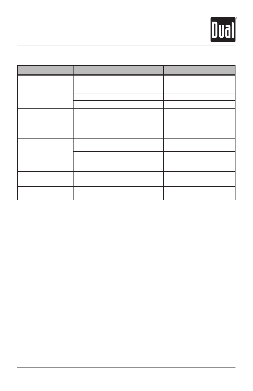
Troubleshooting
Problem Cause Action
Unit will not turn on
(no power)
Yellow wire not connected or incorrect
voltage Red wire not connected or
incorrect voltage
Check connections for proper
voltage (11~16VDC)
Black wire not connected Check connection to ground
Fuse blown Replace fuse
Unit has power
(but no sound)
Speaker wires not connected
Check connections at
speakers
One or more speaker wires touching
each other or touching chassis
ground
Insulate all bare speaker
wires from each other and
chassis ground
Unit blows fuses
Yellow or red wire touching chassis
ground
Check for pinched wire
Speaker wires touching chassis
ground
Check for pinched wire
Incorrect fuse rating Use fuse with correct rating
NO FILE appears
on display
No playable MP3 files found
on the device
Check the device for valid
MP3 files
NO SUPPORT appears
on display
An invalid ID3 tag version is present
Version 1.0 to 2.0 ID3 tags
are supported.
MTR14G INSTALLATION

12
Limited One Year Warranty
MTR14G INSTALLATION
This warranty gives you specific legal rights.
You may also have other rights which vary
from state to state.
Dual Electronics Corp. Inc warrants this
product to the original purchaser to be free
from defects in material and workmanship
for a period of one year from the date of the
original purchase.
Dual Electronics Corp. Inc agrees, at our
option, during the warranty period, to repair
any defect in material or workmanship or to
furnish an equal new, renewed or
comparable product (whichever is deemed
necessary) in exchange without charges,
subject to verification of the defect or
malfunction and proof of the date of
purchas
e. Subsequent replacement
products are warranted for the balance of
the original warranty period.
Who is covered? This warranty is extended
to the original retail purchaser for products
purchased from an authorized Dual dealer
and used in the U.S.A.
Who is covered?
This warranty covers all
defects in material and workmanship in this
product. The following are not covered:
software, installation/ removal costs,
damage resulting from accident, misuse,
abuse, neglect, product modification,
improper installation, incorrect line voltage,
unauthorized repair or failure to follow
instructions supplied with the product, or
damage occurring during return shipment
of the product. Specific license conditions
and copyright notices for the software can
be found via www.dualav.com.
Warranty Coverage
* Limited 1-year warranty. (Proof of
purchase required)
Extend your warranty from 1 year to
2 years when you register online at
www.dualav.com.
What to do?
1. Before you call for service, check the
troubleshooting guide in your owner’s
manual. A slight adjustment of any custom
controls may save you a service call.
2. If you require service during the warranty
period, you must carefully pack the product
(preferably in the original package) and
ship it by prepaid transportation with a
copy of the original receipt from the
retailer to an authorized service center.
3. Please describe your problem
in writing
and include your name, a return UPS
shipping address (P.O. Box not acceptable),
and a daytime phone number with your
shipment.
4. For more information and for the location
of the nearest authorized service center
please contact us by one of the following
methods:
• Call us toll-free at 1-866-382-5476
• E-mail us at cs@dualav.com
Exclusion of Certain Damages: This warranty
is exclusive and in lieu of any and all other
warranties, expressed or implied, including
without limitation the implied warranties of
merchantability and fitness for a particular
purpose and any obligation, liability, right,
claim or remedy in contract or tort, whether
or not arisin
g from the company’s negligence,
actual or imputed. No person or
representative is authorized to assume for
the company any other liability in connection
with the sale of this product. In no event shall
the company be liable for indirect, incidental
or consequential damages.

13
FCC Compliance
This device complies with Part 15 of the FCC Rules. Operation is subject to the
following two conditions:
(1) this device may not cause harmful interference, and
(2) this device must accept any interference received, including interference that may
cause undesired operation.
Warning: Changes or modifications to this unit not expressly approved by the party
responsible for compliance could void the user’s authority to operate the equipment.
Note: This equipment has been tested and found to comply with the limits for a Class
B digital device, pursuant to Part 15 of the FCC Rules. These limits are designed
to provide reasonable protection against harmful interference in a residential
installation. This equipment generates, uses and can radiate radio frequency
energy and,
if not installed and used in accordance with the instructions, may cause
harmful interference to radio communications. However, there is no guarantee that
interference will not occur in a particular installation. If this equipment does cause
harmful interference to radio or television reception, which can be determined
by turning the equipment off and on, the user is encouraged to try to correct the
interference by one or more of the following measures:
• Reorient or relocate the receiving antenna.
• Increase the separation between the equipment and receiver.
• Connect the equipment into an outlet on a circuit different from that to which
the receiver is connected.
• Consult the dealer or an experienced radio/TV technician for help.
MTR14G INSTALLATION

Dual Electronics Corp.
Toll Free: 1-866-382-5476
www.dualav.com
©2024 Dual Electronics Corp. All rights reserved.
The Bluetooth word mark and logos are owned by the Bluetooth SIG, Inc
Other trademarks and trade names are those of their respective owners.
NSC0124-V01
