Technical Support and E-Warranty Certificate
www.vevor.com/support
We continue to be committed to provide you tools with competitive price.
"Save Half", "Half Price" or any other similar expressions used by us only represents an
estimate of savings you might benefit from buying certain tools with us compared to the major
top brands and does not necessarily mean to cover all categories of t ools offered by us. You
are kindly reminded to verify carefully when you are placing an order with us if you are
actually saving half in comparison with the top major brands.
Instruction Manual For
Model No:58 Gallon/116Gallon
Diesel Tank
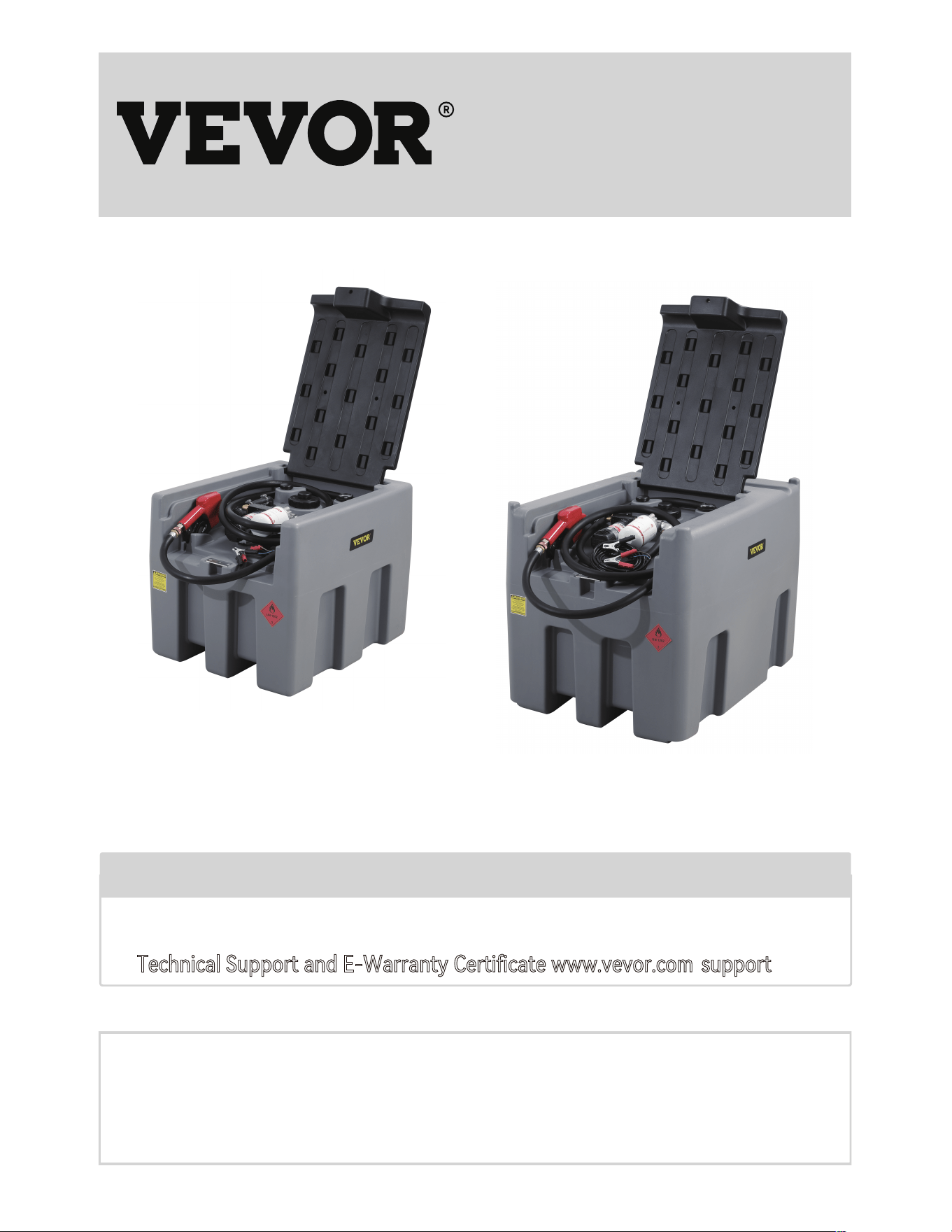
58 Gallon
116Gallon
Have product questions? Need technical suppo? Please feel free to contact us:
NEED HELP? CONTACT US
Technical Support and E-Warranty Certificate www.vevor.com
/
support
!
This is the original instruction, please read all manual instructions carefully before
operating. VEVOR resees clear interpretation of our user manual. The appear-
ance of the product shall be subject to the product you received. Please forgive us
that we won't inform you again if there is any technology or software updates on
our product.
01
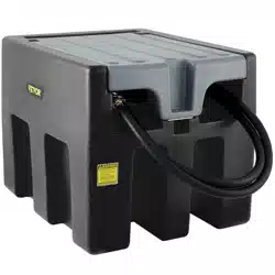
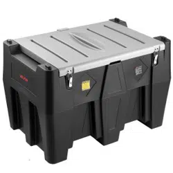
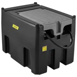
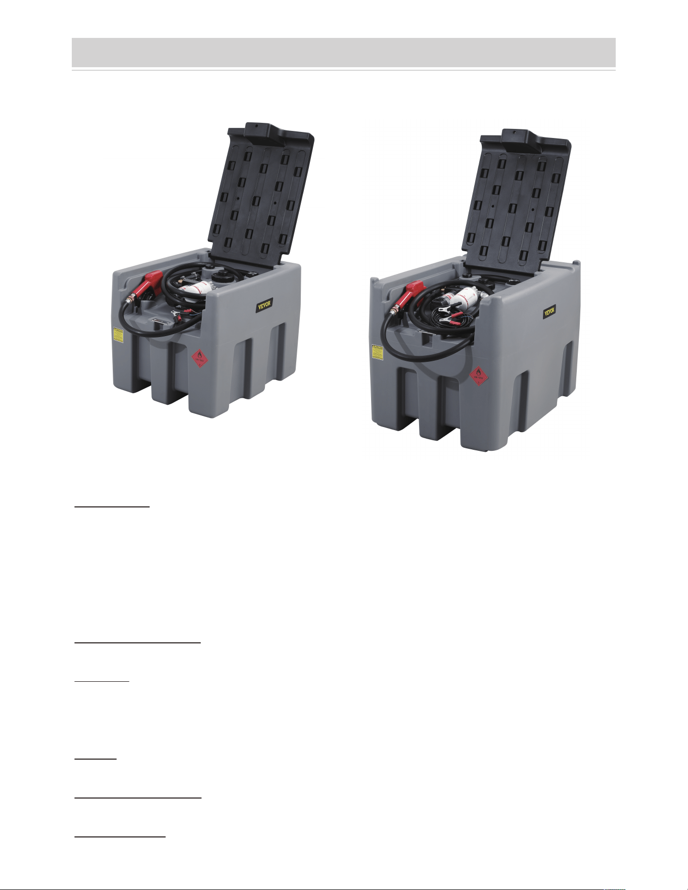
Diesel Tank
02
GENERAL:
All transfer units come standard with an Auto shut-o gun and all pumps feature a
duty cycle for 30 minutes of continuous dispensing, all pumps also contain an
internal bypass that allows for the pump to operate for up to a maximum of three
minutes when the lling nozzle shuts o without damaging the pump or motor.
SPECIFICATIONS:
TANKS:
Made from impact resistant polyethylene, UV stabilized, coloured grey and tted
with lid and breather with 58 gallon or 116 gallon capacity.
GUN: Trigger lling nozzle with automatic shut-o and hose swivel.
DELIVERY HOSE: 4m x %” Diesel Delive hose supplied.
FILTRATION: Suction foot screen lter.
58 Gallon
116Gallon
Instruction Manual For Diesel Tank

03
IMPORTANT OPERATIONAL NOTE- The internal Bypass tted in all diesel pump
models is designed to protect the pump and motor from damage when the trigger
is shut o for a time no greeter the 2�3 minutes.
This is enough time for the operator to switch o the pump or recommence
pumping.
When the nozzle is o and the pump is running the pump pressure increases and
the electric motor load increased using more power (amps) which in turn gener-
ates more heat within both the pump and motor, risking increased wear or possi-
ble if the pump is not switched o.
PUMPS:
Power
Output
Volts Open Flow
Motor Duty
Cycle
Internal
Bypass
Power Cord
RPM
Internal
Fuse
140W 12V DC 40L/min 30 minutes
Yes
4m with alligator
clips
2600 25 amp

04
Warning! This Diesel unit is designed and manufactured solely for the purpose of
caring and pumping Diesel fuel. Under no circumstances may it be used for any
other purposes.
Warning! Prior to installing or using the Diesel unit all operators must have read and
fully understand the contents of this instruction manual as well as all other manuals
supplied, and the safety decal tted to the Diesel unit
Warning! Never allowan inadequately trained person to install or operate the Diesel
unit.
Warning! Ensure the capacity of the vehicle is suitable for the loaded mass of the
diesel unit. Refer to the vehicle operator's manual for safe working loads, correct
secure points and relevant safety instructions.
Warning! Avoid diesel contact with skin and eyes and avoid breathing vapours or
mists. Refer to the Material Data Safety sheet from your Diesel supplieor recom-
mended safety precautions and any required protective equipment for use when
handling. Ensure that all operators and associated personnel are familiar with the
legal regulations and codes of practice that apply to the safe use, storage and
disposal of Diesel.
Warning! This diesel unit should be securely restrained or tied down when being
transpoed on a vehicle
Warning! This Diesel unit should not be lifted when paially or completely full unless
suppoed by an appropriate frame or pallet.
Warning! This unit should never be left unattended while dispensing or being lled.
Warning! Before attempting to ll the tank at a seice station consult the operator
for the correct procedure.
Safety Instructions
WARNING
Before attempting to operate or install the diesel unit carefully read and take
note of the following safety warnings.
Failure to comply with these warnings may result in serious iniu or death.

05
Warning! Do not store the diesel unit within or next to a dwelling or garage attached
to a dwelling.
Warning! Always store the diesel unit in well ventilated open areas.
Warning! Storage of the diesel unit must not be in the proximity of any heating or
ignition sources.
Warning! No combustible waste material or residues shall be permitted to remain in
or around areas in which diesel is stored or decanted
Warning! Any spillage shall be cleaned up immediately and the materials used in the
clean-up shall be disposed of safely and in accordance with any legal regulations
and codes of practice that apply to the safe use, storage and disposal of Diesel.
Warning! Ensure that the electrical lead(s) are always in good condition and the wire
is not exposed through the plastic coating. Do not allow the lead to become tightly
knotted, crushed or pinched.

06
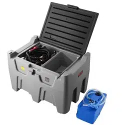
PREPARING THE TRANSFER UNIT FOR OPERATION:
For transpo purposes some transfer units will be supplied with the Delive hose
and Automatic Shut-o gun disconnected from the pump. Before attempting to
pump any Diesel ensure that the delive hose is securely tted to the pump's outlet,
and that the Automatic Shut-o gun (with swivel) is tted to the other end of the
delive hose.
CONNECTING TO A POWER SUPPLY:
All the diesel transfer units are tted with DC electric motors that are supplied with
alligator clips that can be connected directly to a 12-volt DC batte. Connect the
Red alligator clip to the positive terminal and the black alligator clip to the negative
terminal. If the pump runs backwards, simply swap the clips on the batte. If you
intend to extend the cable or add a plug, make sure it is of sucient capacity
25Amps
FILLING THE DIESEL UNIT:
Ensure that the tank is suppoed on an even base capable of taking the weight. No
Special equipment is required for lling the tank, however when the lid has been
removed from the tank take care not to introduce contaminants into the tank via the
ller neck and ensure that the lid is kept free of contaminating paicles while lling.
TRANSFERING DIESEL:
The pump will need to prime itself upon rst use. Turn the pump on and depress the
trigger to allow air to bleed from the hoses, after a sho time the pump will have
primed and delive will commence. We recommend for this rst priming that the lid
is removed from the tank and the nozzle is directed back into the tank while pumping
to avoid spillage or loss of Diesel, with this done the unit is now ready to operate.
To dispense the pump must be turned on and the nozzles trigger depressed, the
nozzle features an automatic shut-o which operates when uid contacts the outer
nozzle. Ouce the auto shut o operates turn o the pump within 2 or 3 minutes so as
not to allow the motor to run for longer than its specied duty cycle.
Operation and Installation

07
The pumps have been designed and built to require minimal maintenance however it
is still impoant that you Always remove the pump from the power source before
any inspection.
The Vanes in the head of the pump will wear oveime and require replacement. To
extend the life of the Vanes, ensure that the lters are kept clean and the tank free of
contaminants. If a reduced ow rate is noticeable, or a screeching sound is heard
from the pump, di or debris may have entered the pumps and requires immediate
cleaning before pas are permanently damaged. Periodically check the suction foot
lter to ensure that is clean and free of debris. This should be done if there is a
noticeable decrease in diesel ow rate. There is also a coarse screen mesh at the inlet
ofthe Auto shut-o gun and can be checked by removing the gun from the swivel.
Maintenance

08
Troubleshoot
TROUBLE SHOOTING GUIDE
Problem Solution
Pump does not operate
•Ensure batte wires are connected to batte properly. Red
Clip to +ve
•Check Fuse (25A) under plastic pump switch cover is intact.
•Remove pump end cover, connect power to White & Black
wires to test
•If motor still does not operate, remove 3 x head cover bolts &
check for rust or obstruction, do not over tighten the screws
when replacing the cover as this will jam the rotor against the
cover and also prevent the electric motor from turning and
blow the fuse.
•This can happen when pump is operated in bypass mode for
longer than 3 minutes or if low voltage/amps. Ensure that
pump is not left running for longer than 3 minutes without
depressing Transfer Gun trigger.
•The wiring loom has been extended using wire of insucient
gauge. 25A wire is required and a matching connector.
• This can be caused by di or debris entering the pump and
becoming caught in the working pas. Remove the end cover
of the pump by rst unscrewing the three Socket Head screws
and lifting o the cover. Clean the impeller vanes ensuring you
remove any di paicles caught between the ends of the vanes
and the impeller housing. Do not over-tighten head screws
when reassembling�
• The non-return valve in the outlet of the pump may be
jammed shut. Remove the outlet hose from the pump. Operate
the white plastic valve in the outlet po of the pump manually
(by pushing it in and out), to ensure it moves freely.
•Remove gun from hose & re-test, Run the hose into the tank
lling neck while checking.
•If ow improves, check hole in the end of the nozzle for
blockage
•Replace gun as required.
•Check red alligator clip tted to positive terminal, black to
negative. If it is the wrong way around the pump runs
backwards.
•Check suction hose and foot lter are immersed in diesel. The
suction hose may be bent up out of the diesel.
•If pump is brand new or has not been used in a long period of
time unscrew automatic gun from hose and put hose in ller
neck to prime pump
To Test & Repair if Pump does
not
operate
Pump Wiring Overheating
Pump makes a
squealing/scratching sound
while running.
Pump stalls when Transfer
Gun trigger is released, and
pump is running.
To Test & Repair if the Pump
is running but low or nil ow
from nozzle
Pump runs but does not
pump

Manufacturer: Shanghaimuxinmuyeyouxiangongsi
Address: Shuangchenglu 803nong11hao1602A-1609shi, baosh an qu,
shanghai 200000 CN.
Imported to AUS: SIHAO PTY LTD, 1 ROKEVA STREETEASTWOOD NSW
2122 Australia
Imported to USA: Sanven Technology Ltd., Suite 250, 9166 Anaheim Plac e,
Rancho Cucamonga, CA 91730
REPEC
E-Cr sStu GmbH
Main
o
z
s
er Lan s rd t .69, 60329 Frankfurt am Main.
REPUK
YH CONSULTING LIMITED.
C/O YH Cons ulting Limited Office 147, Centurion House,
London Road, Staines-up on -Thames, Surrey, TW18 4AX
09

Technical Support and E-Warranty Certificate
www.vevor.com/support