
PANTONG 1665C
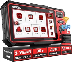
ANCEL DS300
User Manual
01
Choose a languageProduct Overview
03
Connect the Ancel DS300 with your
vehicle through the OBDII port
02
Technical Specifications
04
Turn on the Ancel DS300
3
2
4
5
6
7
8
119
1
10
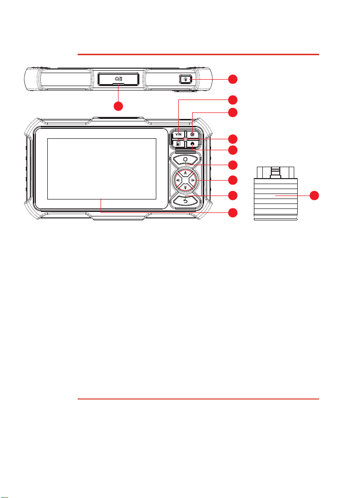
1. Charging Port: TYPE-C charging port & development system debugging USB port which can
support USB device.
2. Power/Screen Lock Button: Long press for 3 seconds to turn on or off, single press to
lock/unlock the screen.
3. VIN Button: Read vehicle VIN code shortcut button.
4. Settings Button: System settings shortcut button.
5. Report Button: Diagnostic report shotcut button.
6. Home Button: Back to home page.
7. Confirm Button: Press to confirm.
8. Selection Buttons: Up, donw, left and right direction selection.
9. Return Button: Return to the previous page.
10. Touch Screen:7 inches touch screen (1024*600 resolution).
11. VCI: Vehicle Communications Interface, connect VCI to car OBD port for diagnosis.
Product host
Working Environment: 0°C ~ 50°C (32°F ~ 122°F)
Storage Environment: -20°C ~ 60°C (-4°F ~ 140°F)
Working Voltage: 5V
Working Current: ≤ 2.5A
VCI
Working Voltage: 9-18V
Working Current: ≤ 130mA
Supported Protocols:
SAE J1850 PWM, SAE J1850 VPW, ISO 9141-2 ISO, ISO 14230-4 KWP, ISO 15765-4 CAN.
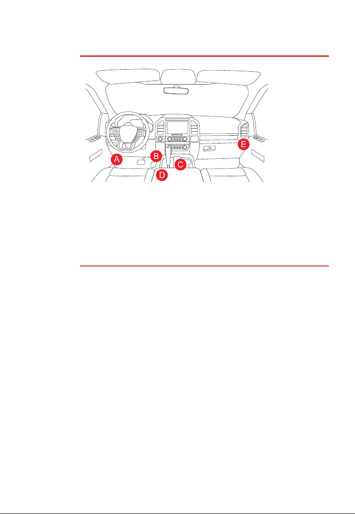
Usually, the OBD port is located under the dashboard, above the pedal on the driver’s side. The five
locations shown lite the picture are common OBDII port locations.
When the power button is long pressed and the product is turned on, the product interface above
will be displayed.
05
06
Connect to Wi-Fi
First, please select the language you need. After selecting, the operation page will display the
language you selected.
The system will automatically search all available Wi-Fi networks and you can choose the “Wi-Fi”
needed. Notice the “Wi-Fi” must be set before use.
Here we list some common questions and answers related to this tool.
1. Q: Why does it have no responses when connected to a vehicle?
A: Check whether the connection with the vehicle diagnostic port is proper, whether the ignition
You can do some basic set up in this page. Include Wi-Fi, screen brightness, language, time zone,
and so on.
· Feedback: You can feedback the diagnostic software/app bugs to us for analysis and improve-
ments.
· Update: This module allows you to update the diagnostic software & App and set up frequently
used software.
· Screenshots: Turn on this switch to take a screen capture.
· Screen floating window: Turn on this switch to record the screen operation video.
· Network: Set the connectable Wi-Fi network.
· Firmware fix: Used to update the firmware.
· Language: Select the tool language .
· Time zone: Choose the time zone of the current location, then the system will automatically
configure the time according to the time zone you chose.
Choose privacy agreement
07
08
Functions Description
09
Settings
10
FAQ
11
Warranty Terms
Please read carefully and check the box to agree to the agreement. You need to agree to the
agreement before you can use the product.
The Ancel DS300 home page has the following functions:
This warranty applies only to users and distributors who purchase ANCEL products through normal
procedures. Within one year from the date of delivery, ANCEL warrants its electronic products for
damages caused by defects in materials or workmanship. Damages to the equipment or
components because of abuse, unauthorized modification, use for non-designed purposes,
operation in a manner not specified in the instructions, etc. are not covered by this warranty. The
compensation for dashboard damage caused by the defect of this equipment is limited to repair or
replacement. ANCEL does not bear any indirect and incidental losses. ANCEL will judge the nature
of the equipment damage according to its prescribed inspection methods. No agents, employees or
business representatives of ANCEL are authorized to make any confirmation, notice or promise
related to ANCEL products.
OBDSPACE Tech Co., Ltd
Service Line: 0755-81751202
Products tutorial, videos, Q&A and coverage list are available on ANCEL official website.
8.1 Autoseach:
Automatic scanning of car models' VIN, Automatically identify vehicle make, model and year.
8.2 Diagnose:
Automatic scanning of car models' VIN, Automatically identify vehicle make, model and year.
OBD&IM:
9 emission-related module diagnosis.
Demo:
Experience the diagnostic process through demo.
History:
Diagnosis records.
8.6 Consult:
OBD Fault Code Library:
The OBD fault code prompted during the diagnosis process can be used to query the fault
description.
Coverage lists:
Quickly check the models and functions supported by the current device.
Learning:
Videos contain guidelines for equipment use, maintenance, and diagnostics.
Video:
The learning course demonstrates how to operate the tool.
User Manual:
Help technicians quickly grasp the usage of equipment and efficiently improvediagnostic
capabilities.
8.3 OBD:
Support OBD II and EOBD protocols after 1996. You can check the protocols supported by the
vehicle.
8.4 Maintenance:
Host with rich maintenance and reset functions,namely, Maintenance light reset, Steering angle
reset, Battery matching, ABS exhaust, Throttle matching, Brake pad reset, DPF regeneration,
Anti-theft matching, Injector coding, Tire pressure reset, Suspension level calibration, Headlight
matching, Gearbox matching, Sunroof initialization, EGR Adaption, Gear Learning, ODO Reset,
Airbag Reset, Transport Mode, A/F Reset, Stop/Start Reset, NOx Sensor Reset, AdBlue Reset
(Diesel Engine Exhaust Gas Filter), Seat Calibration, Coolant Bleeding, Tyre Reset, Windows
Calibration and Language Setting.
8.5 File:
It is used to record and establish the files of the diagnosed vehicles. The files are created based
on the vehicle VIN and the check time, including all diagnosticrelated data such as diagnostic
reports, data stream records and screenshots.
8.7 Module:
A variety of external function modules can be connected.For example, USB printer, USB
oscilloscope, USB endoscope, Bluetooth battery tester, Bluetooth tire pressure stick (TPMS),
etc.
8.8 Feedback:
If you use the fault feedback function to us during the diagnosis process, the feedback record
will be displayed here.
8.9 Update:
This module allows you to update the diagnostic software & App and set frequently used
software. If you did not download the software at registration or some software is newly
updated, you may use this option to download it or keep it synchronized with the latest version.
8.10 Settings:
Common system settings can be made here to modify and add information.
switch is on, and whether the tool supports the vehicle.
2. Q: Why does the system stop while reading the data stream?
A: This may be caused by loose diagnostic connection. Please unplug the connector and
reconnect it firmly.
3. Q: Communication error with vehicle ECU?
A: Please confirm:
· Whether diagnostic connector is correctly connected.
· Whether ignition switch is ON.
· If all checks are normal, please send the vehicle year,car make, model and VIN number to us
by Feedback function.
4. Q: Why does the screen flash when the engine ignition starts?
A: It is normal and caused by electromagnetic interference.
5. Q: How to upgrade the system software?
A: 1. Start the tool and ensure a stable Internet connection.
2. Go to "Settings" -> “App Update”, click "OTA" and then click “check version” to enter the
system upgrade interface.
3. Complete the process by following the instructions on the screen step by step. It may take a
few minutes. After successfully completing the upgrade, the tool will automatically restart and
enter the main interface.
页面 8页面 7 页面 10页面 9页面 6页面 5
12
RF exposure statement:
Federal Communications Commission (FCC) Statement
This device complies with part 15 of the FCC Rules. Operation is subject to the following two
conditions: (1) This device may not cause harmful interference, and (2) this device must accept any
interference received, including interference that may cause undesired operation.
Note: This equipment has been tested and found to comply with the limits for a Class B digital
device, pursuant to part 15 of the FCC Rules. These limits are designed to provide reasonable
protection against harmful interference in a residential installation. This equipment generates, uses
and can radiate radio frequency energy and, if not installed and used in accordance with the
instructions, may cause harmful interference to radio communications. However, there is no
guarantee that interference will not occur in a particular installation. If this equipment does cause
harmful interference to radio or television reception, which can be determined by turning the
equipment off and on, the user is encouraged to try to correct the interference by one or more of
the following measures:
●Reorient or relocate the receiving antenna.
●Increase the separation between the equipment and receiver.
●Connect the equipment into an outlet on a circuit different from that to which the receiver is
connected.
●Consult the dealer or an experienced radio/TV technician for help.
Warning: Changes or modifications made to this device not expressly approved by
BVT Video Technology Shenzhen Limited
may void the FCC authorization to operate this device.
Note: The manufacturer is not responsible for any radio or TV interference caused by unauthorized
modifications to this equipment. Such modifications could void the user’s authority to operate the
equipment.
RF exposure statement
For Product Host: The device has been evaluated to meet general RF exposure requirement. The
device can be used in portable exposure condition without restriction.
For VCI:
The transmitter must not be colocated or operated in conjunction with any other antenna
or
transmitter. This equipment complies with the FCC RF radiation exposure limits set forth for
an uncontrolled environment. This equipment should be installed and operated with a Minimum
distance of 20cm between the radiator and any part of your body.
PANTONG 1665C
ANCEL DS300
User Manual
01
Choose a languageProduct Overview
03
Connect the Ancel DS300 with your
vehicle through the OBDII port
02
Technical Specifications
04
Turn on the Ancel DS300
3
2
4
5
6
7
8
119
1
10
1. Charging Port: TYPE-C charging port & development system debugging USB port which can
support USB device.
2. Power/Screen Lock Button: Long press for 3 seconds to turn on or off, single press to
lock/unlock the screen.
3. VIN Button: Read vehicle VIN code shortcut button.
4. Settings Button: System settings shortcut button.
5. Report Button: Diagnostic report shotcut button.
6. Home Button: Back to home page.
7. Confirm Button: Press to confirm.
8. Selection Buttons: Up, donw, left and right direction selection.
9. Return Button: Return to the previous page.
10. Touch Screen:7 inches touch screen (1024*600 resolution).
11. VCI: Vehicle Communications Interface, connect VCI to car OBD port for diagnosis.
Product host
Working Environment: 0°C ~ 50°C (32°F ~ 122°F)
Storage Environment: -20°C ~ 60°C (-4°F ~ 140°F)
Working Voltage: 5V
Working Current: ≤ 2.5A
VCI
Working Voltage: 9-18V
Working Current: ≤ 130mA
Supported Protocols:
SAE J1850 PWM, SAE J1850 VPW, ISO 9141-2 ISO, ISO 14230-4 KWP, ISO 15765-4 CAN.
Usually, the OBD port is located under the dashboard, above the pedal on the driver’s side. The five
locations shown lite the picture are common OBDII port locations.
When the power button is long pressed and the product is turned on, the product interface above
will be displayed.
05
06
Connect to Wi-Fi
First, please select the language you need. After selecting, the operation page will display the
language you selected.
The system will automatically search all available Wi-Fi networks and you can choose the “Wi-Fi”
needed. Notice the “Wi-Fi” must be set before use.
Here we list some common questions and answers related to this tool.
1. Q: Why does it have no responses when connected to a vehicle?
A: Check whether the connection with the vehicle diagnostic port is proper, whether the ignition
You can do some basic set up in this page. Include Wi-Fi, screen brightness, language, time zone,
and so on.
· Feedback: You can feedback the diagnostic software/app bugs to us for analysis and improve-
ments.
· Update: This module allows you to update the diagnostic software & App and set up frequently
used software.
· Screenshots: Turn on this switch to take a screen capture.
· Screen floating window: Turn on this switch to record the screen operation video.
· Network: Set the connectable Wi-Fi network.
· Firmware fix: Used to update the firmware.
· Language: Select the tool language .
· Time zone: Choose the time zone of the current location, then the system will automatically
configure the time according to the time zone you chose.
Choose privacy agreement
07
08
Functions Description
09
Settings
10
FAQ
11
Warranty Terms
Please read carefully and check the box to agree to the agreement. You need to agree to the
agreement before you can use the product.
The Ancel DS300 home page has the following functions:
This warranty applies only to users and distributors who purchase ANCEL products through normal
procedures. Within one year from the date of delivery, ANCEL warrants its electronic products for
damages caused by defects in materials or workmanship. Damages to the equipment or
components because of abuse, unauthorized modification, use for non-designed purposes,
operation in a manner not specified in the instructions, etc. are not covered by this warranty. The
compensation for dashboard damage caused by the defect of this equipment is limited to repair or
replacement. ANCEL does not bear any indirect and incidental losses. ANCEL will judge the nature
of the equipment damage according to its prescribed inspection methods. No agents, employees or
business representatives of ANCEL are authorized to make any confirmation, notice or promise
related to ANCEL products.
OBDSPACE Tech Co., Ltd
Service Line: 0755-81751202
Products tutorial, videos, Q&A and coverage list are available on ANCEL official website.
8.1 Autoseach:
Automatic scanning of car models' VIN, Automatically identify vehicle make, model and year.
8.2 Diagnose:
Automatic scanning of car models' VIN, Automatically identify vehicle make, model and year.
OBD&IM:
9 emission-related module diagnosis.
Demo:
Experience the diagnostic process through demo.
History:
Diagnosis records.
8.6 Consult:
OBD Fault Code Library:
The OBD fault code prompted during the diagnosis process can be used to query the fault
description.
Coverage lists:
Quickly check the models and functions supported by the current device.
Learning:
Videos contain guidelines for equipment use, maintenance, and diagnostics.
Video:
The learning course demonstrates how to operate the tool.
User Manual:
Help technicians quickly grasp the usage of equipment and efficiently improvediagnostic
capabilities.
8.3 OBD:
Support OBD II and EOBD protocols after 1996. You can check the protocols supported by the
vehicle.
8.4 Maintenance:
Host with rich maintenance and reset functions,namely, Maintenance light reset, Steering angle
reset, Battery matching, ABS exhaust, Throttle matching, Brake pad reset, DPF regeneration,
Anti-theft matching, Injector coding, Tire pressure reset, Suspension level calibration, Headlight
matching, Gearbox matching, Sunroof initialization, EGR Adaption, Gear Learning, ODO Reset,
Airbag Reset, Transport Mode, A/F Reset, Stop/Start Reset, NOx Sensor Reset, AdBlue Reset
(Diesel Engine Exhaust Gas Filter), Seat Calibration, Coolant Bleeding, Tyre Reset, Windows
Calibration and Language Setting.
8.5 File:
It is used to record and establish the files of the diagnosed vehicles. The files are created based
on the vehicle VIN and the check time, including all diagnosticrelated data such as diagnostic
reports, data stream records and screenshots.
8.7 Module:
A variety of external function modules can be connected.For example, USB printer, USB
oscilloscope, USB endoscope, Bluetooth battery tester, Bluetooth tire pressure stick (TPMS),
etc.
8.8 Feedback:
If you use the fault feedback function to us during the diagnosis process, the feedback record
will be displayed here.
8.9 Update:
This module allows you to update the diagnostic software & App and set frequently used
software. If you did not download the software at registration or some software is newly
updated, you may use this option to download it or keep it synchronized with the latest version.
8.10 Settings:
Common system settings can be made here to modify and add information.
switch is on, and whether the tool supports the vehicle.
2. Q: Why does the system stop while reading the data stream?
A: This may be caused by loose diagnostic connection. Please unplug the connector and
reconnect it firmly.
3. Q: Communication error with vehicle ECU?
A: Please confirm:
· Whether diagnostic connector is correctly connected.
· Whether ignition switch is ON.
· If all checks are normal, please send the vehicle year,car make, model and VIN number to us
by Feedback function.
4. Q: Why does the screen flash when the engine ignition starts?
A: It is normal and caused by electromagnetic interference.
5. Q: How to upgrade the system software?
A: 1. Start the tool and ensure a stable Internet connection.
2. Go to "Settings" -> “App Update”, click "OTA" and then click “check version” to enter the
system upgrade interface.
3. Complete the process by following the instructions on the screen step by step. It may take a
few minutes. After successfully completing the upgrade, the tool will automatically restart and
enter the main interface.
页面 8页面 7 页面 10页面 9页面 6页面 5
12
RF exposure statement:
Federal Communications Commission (FCC) Statement
This device complies with part 15 of the FCC Rules. Operation is subject to the following two
conditions: (1) This device may not cause harmful interference, and (2) this device must accept any
interference received, including interference that may cause undesired operation.
Note: This equipment has been tested and found to comply with the limits for a Class B digital
device, pursuant to part 15 of the FCC Rules. These limits are designed to provide reasonable
protection against harmful interference in a residential installation. This equipment generates, uses
and can radiate radio frequency energy and, if not installed and used in accordance with the
instructions, may cause harmful interference to radio communications. However, there is no
guarantee that interference will not occur in a particular installation. If this equipment does cause
harmful interference to radio or television reception, which can be determined by turning the
equipment off and on, the user is encouraged to try to correct the interference by one or more of
the following measures:
●Reorient or relocate the receiving antenna.
●Increase the separation between the equipment and receiver.
●Connect the equipment into an outlet on a circuit different from that to which the receiver is
connected.
●Consult the dealer or an experienced radio/TV technician for help.
Warning: Changes or modifications made to this device not expressly approved by
BVT Video Technology Shenzhen Limited
may void the FCC authorization to operate this device.
Note: The manufacturer is not responsible for any radio or TV interference caused by unauthorized
modifications to this equipment. Such modifications could void the user’s authority to operate the
equipment.
RF exposure statement
For Product Host: The device has been evaluated to meet general RF exposure requirement. The
device can be used in portable exposure condition without restriction.
For VCI:
The transmitter must not be colocated or operated in conjunction with any other antenna
or
transmitter. This equipment complies with the FCC RF radiation exposure limits set forth for
an uncontrolled environment. This equipment should be installed and operated with a Minimum
distance of 20cm between the radiator and any part of your body.

PANTONG 1665C
ANCEL DS300
User Manual
01
Choose a languageProduct Overview
03
Connect the Ancel DS300 with your
vehicle through the OBDII port
02
Technical Specifications
04
Turn on the Ancel DS300
3
2
4
5
6
7
8
119
1
10
1. Charging Port: TYPE-C charging port & development system debugging USB port which can
support USB device.
2. Power/Screen Lock Button: Long press for 3 seconds to turn on or off, single press to
lock/unlock the screen.
3. VIN Button: Read vehicle VIN code shortcut button.
4. Settings Button: System settings shortcut button.
5. Report Button: Diagnostic report shotcut button.
6. Home Button: Back to home page.
7. Confirm Button: Press to confirm.
8. Selection Buttons: Up, donw, left and right direction selection.
9. Return Button: Return to the previous page.
10. Touch Screen:7 inches touch screen (1024*600 resolution).
11. VCI: Vehicle Communications Interface, connect VCI to car OBD port for diagnosis.
Product host
Working Environment: 0°C ~ 50°C (32°F ~ 122°F)
Storage Environment: -20°C ~ 60°C (-4°F ~ 140°F)
Working Voltage: 5V
Working Current: ≤ 2.5A
VCI
Working Voltage: 9-18V
Working Current: ≤ 130mA
Supported Protocols:
SAE J1850 PWM, SAE J1850 VPW, ISO 9141-2 ISO, ISO 14230-4 KWP, ISO 15765-4 CAN.
Usually, the OBD port is located under the dashboard, above the pedal on the driver’s side. The five
locations shown lite the picture are common OBDII port locations.
When the power button is long pressed and the product is turned on, the product interface above
will be displayed.
05
06
Connect to Wi-Fi
First, please select the language you need. After selecting, the operation page will display the
language you selected.
The system will automatically search all available Wi-Fi networks and you can choose the “Wi-Fi”
needed. Notice the “Wi-Fi” must be set before use.
Here we list some common questions and answers related to this tool.
1. Q: Why does it have no responses when connected to a vehicle?
A: Check whether the connection with the vehicle diagnostic port is proper, whether the ignition
You can do some basic set up in this page. Include Wi-Fi, screen brightness, language, time zone,
and so on.
· Feedback: You can feedback the diagnostic software/app bugs to us for analysis and improve-
ments.
· Update: This module allows you to update the diagnostic software & App and set up frequently
used software.
· Screenshots: Turn on this switch to take a screen capture.
· Screen floating window: Turn on this switch to record the screen operation video.
· Network: Set the connectable Wi-Fi network.
· Firmware fix: Used to update the firmware.
· Language: Select the tool language .
· Time zone: Choose the time zone of the current location, then the system will automatically
configure the time according to the time zone you chose.
Choose privacy agreement
07
08
Functions Description
09
Settings
10
FAQ
11
Warranty Terms
Please read carefully and check the box to agree to the agreement. You need to agree to the
agreement before you can use the product.
The Ancel DS300 home page has the following functions:
This warranty applies only to users and distributors who purchase ANCEL products through normal
procedures. Within one year from the date of delivery, ANCEL warrants its electronic products for
damages caused by defects in materials or workmanship. Damages to the equipment or
components because of abuse, unauthorized modification, use for non-designed purposes,
operation in a manner not specified in the instructions, etc. are not covered by this warranty. The
compensation for dashboard damage caused by the defect of this equipment is limited to repair or
replacement. ANCEL does not bear any indirect and incidental losses. ANCEL will judge the nature
of the equipment damage according to its prescribed inspection methods. No agents, employees or
business representatives of ANCEL are authorized to make any confirmation, notice or promise
related to ANCEL products.
OBDSPACE Tech Co., Ltd
Service Line: 0755-81751202
Customer Service Email: [email protected] Official Website: www.anceltech.com
Products tutorial, videos, Q&A and coverage list are available on ANCEL official website.
8.1 Autoseach:
Automatic scanning of car models' VIN, Automatically identify vehicle make, model and year.
8.2 Diagnose:
Automatic scanning of car models' VIN, Automatically identify vehicle make, model and year.
OBD&IM:
9 emission-related module diagnosis.
Demo:
Experience the diagnostic process through demo.
History:
Diagnosis records.
8.6 Consult:
OBD Fault Code Library:
The OBD fault code prompted during the diagnosis process can be used to query the fault
description.
Coverage lists:
Quickly check the models and functions supported by the current device.
Learning:
Videos contain guidelines for equipment use, maintenance, and diagnostics.
Video:
The learning course demonstrates how to operate the tool.
User Manual:
Help technicians quickly grasp the usage of equipment and efficiently improvediagnostic
capabilities.
8.3 OBD:
Support OBD II and EOBD protocols after 1996. You can check the protocols supported by the
vehicle.
8.4 Maintenance:
Host with rich maintenance and reset functions,namely, Maintenance light reset, Steering angle
reset, Battery matching, ABS exhaust, Throttle matching, Brake pad reset, DPF regeneration,
Anti-theft matching, Injector coding, Tire pressure reset, Suspension level calibration, Headlight
matching, Gearbox matching, Sunroof initialization, EGR Adaption, Gear Learning, ODO Reset,
Airbag Reset, Transport Mode, A/F Reset, Stop/Start Reset, NOx Sensor Reset, AdBlue Reset
(Diesel Engine Exhaust Gas Filter), Seat Calibration, Coolant Bleeding, Tyre Reset, Windows
Calibration and Language Setting.
8.5 File:
It is used to record and establish the files of the diagnosed vehicles. The files are created based
on the vehicle VIN and the check time, including all diagnosticrelated data such as diagnostic
reports, data stream records and screenshots.
8.7 Module:
A variety of external function modules can be connected.For example, USB printer, USB
oscilloscope, USB endoscope, Bluetooth battery tester, Bluetooth tire pressure stick (TPMS),
etc.
8.8 Feedback:
If you use the fault feedback function to us during the diagnosis process, the feedback record
will be displayed here.
8.9 Update:
This module allows you to update the diagnostic software & App and set frequently used
software. If you did not download the software at registration or some software is newly
updated, you may use this option to download it or keep it synchronized with the latest version.
8.10 Settings:
Common system settings can be made here to modify and add information.
switch is on, and whether the tool supports the vehicle.
2. Q: Why does the system stop while reading the data stream?
A: This may be caused by loose diagnostic connection. Please unplug the connector and
reconnect it firmly.
3. Q: Communication error with vehicle ECU?
A: Please confirm:
· Whether diagnostic connector is correctly connected.
· Whether ignition switch is ON.
· If all checks are normal, please send the vehicle year,car make, model and VIN number to us
by Feedback function.
4. Q: Why does the screen flash when the engine ignition starts?
A: It is normal and caused by electromagnetic interference.
5. Q: How to upgrade the system software?
A: 1. Start the tool and ensure a stable Internet connection.
2. Go to "Settings" -> “App Update”, click "OTA" and then click “check version” to enter the
system upgrade interface.
3. Complete the process by following the instructions on the screen step by step. It may take a
few minutes. After successfully completing the upgrade, the tool will automatically restart and
enter the main interface.
页面 8页面 7 页面 10页面 9页面 6页面 5
12
RF exposure statement:
Federal Communications Commission (FCC) Statement
This device complies with part 15 of the FCC Rules. Operation is subject to the following two
conditions: (1) This device may not cause harmful interference, and (2) this device must accept any
interference received, including interference that may cause undesired operation.
Note: This equipment has been tested and found to comply with the limits for a Class B digital
device, pursuant to part 15 of the FCC Rules. These limits are designed to provide reasonable
protection against harmful interference in a residential installation. This equipment generates, uses
and can radiate radio frequency energy and, if not installed and used in accordance with the
instructions, may cause harmful interference to radio communications. However, there is no
guarantee that interference will not occur in a particular installation. If this equipment does cause
harmful interference to radio or television reception, which can be determined by turning the
equipment off and on, the user is encouraged to try to correct the interference by one or more of
the following measures:
●Reorient or relocate the receiving antenna.
●Increase the separation between the equipment and receiver.
●Connect the equipment into an outlet on a circuit different from that to which the receiver is
connected.
●Consult the dealer or an experienced radio/TV technician for help.
Warning: Changes or modifications made to this device not expressly approved by
BVT Video Technology Shenzhen Limited
may void the FCC authorization to operate this device.
Note: The manufacturer is not responsible for any radio or TV interference caused by unauthorized
modifications to this equipment. Such modifications could void the user’s authority to operate the
equipment.
RF exposure statement
For Product Host: The device has been evaluated to meet general RF exposure requirement. The
device can be used in portable exposure condition without restriction.
For VCI:
The transmitter must not be colocated or operated in conjunction with any other antenna
or
transmitter. This equipment complies with the FCC RF radiation exposure limits set forth for
an uncontrolled environment. This equipment should be installed and operated with a Minimum
distance of 20cm between the radiator and any part of your body.

PANTONG 1665C
ANCEL DS300
User Manual
01
Choose a languageProduct Overview
03
Connect the Ancel DS300 with your
vehicle through the OBDII port
02
Technical Specifications
04
Turn on the Ancel DS300
3
2
4
5
6
7
8
119
1
10
1. Charging Port: TYPE-C charging port & development system debugging USB port which can
support USB device.
2. Power/Screen Lock Button: Long press for 3 seconds to turn on or off, single press to
lock/unlock the screen.
3. VIN Button: Read vehicle VIN code shortcut button.
4. Settings Button: System settings shortcut button.
5. Report Button: Diagnostic report shotcut button.
6. Home Button: Back to home page.
7. Confirm Button: Press to confirm.
8. Selection Buttons: Up, donw, left and right direction selection.
9. Return Button: Return to the previous page.
10. Touch Screen:7 inches touch screen (1024*600 resolution).
11. VCI: Vehicle Communications Interface, connect VCI to car OBD port for diagnosis.
Product host
Working Environment: 0°C ~ 50°C (32°F ~ 122°F)
Storage Environment: -20°C ~ 60°C (-4°F ~ 140°F)
Working Voltage: 5V
Working Current: ≤ 2.5A
VCI
Working Voltage: 9-18V
Working Current: ≤ 130mA
Supported Protocols:
SAE J1850 PWM, SAE J1850 VPW, ISO 9141-2 ISO, ISO 14230-4 KWP, ISO 15765-4 CAN.
Usually, the OBD port is located under the dashboard, above the pedal on the driver’s side. The five
locations shown lite the picture are common OBDII port locations.
When the power button is long pressed and the product is turned on, the product interface above
will be displayed.
05
06
Connect to Wi-Fi
First, please select the language you need. After selecting, the operation page will display the
language you selected.
The system will automatically search all available Wi-Fi networks and you can choose the “Wi-Fi”
needed. Notice the “Wi-Fi” must be set before use.
Here we list some common questions and answers related to this tool.
1. Q: Why does it have no responses when connected to a vehicle?
A: Check whether the connection with the vehicle diagnostic port is proper, whether the ignition
You can do some basic set up in this page. Include Wi-Fi, screen brightness, language, time zone,
and so on.
· Feedback: You can feedback the diagnostic software/app bugs to us for analysis and improve-
ments.
· Update: This module allows you to update the diagnostic software & App and set up frequently
used software.
· Screenshots: Turn on this switch to take a screen capture.
· Screen floating window: Turn on this switch to record the screen operation video.
· Network: Set the connectable Wi-Fi network.
· Firmware fix: Used to update the firmware.
· Language: Select the tool language .
· Time zone: Choose the time zone of the current location, then the system will automatically
configure the time according to the time zone you chose.
Choose privacy agreement
07
08
Functions Description
09
Settings
10
FAQ
11
Warranty Terms
Please read carefully and check the box to agree to the agreement. You need to agree to the
agreement before you can use the product.
The Ancel DS300 home page has the following functions:
This warranty applies only to users and distributors who purchase ANCEL products through normal
procedures. Within one year from the date of delivery, ANCEL warrants its electronic products for
damages caused by defects in materials or workmanship. Damages to the equipment or
components because of abuse, unauthorized modification, use for non-designed purposes,
operation in a manner not specified in the instructions, etc. are not covered by this warranty. The
compensation for dashboard damage caused by the defect of this equipment is limited to repair or
replacement. ANCEL does not bear any indirect and incidental losses. ANCEL will judge the nature
of the equipment damage according to its prescribed inspection methods. No agents, employees or
business representatives of ANCEL are authorized to make any confirmation, notice or promise
related to ANCEL products.
OBDSPACE Tech Co., Ltd
Service Line: 0755-81751202
Products tutorial, videos, Q&A and coverage list are available on ANCEL official website.
8.1 Autoseach:
Automatic scanning of car models' VIN, Automatically identify vehicle make, model and year.
8.2 Diagnose:
Automatic scanning of car models' VIN, Automatically identify vehicle make, model and year.
OBD&IM:
9 emission-related module diagnosis.
Demo:
Experience the diagnostic process through demo.
History:
Diagnosis records.
8.6 Consult:
OBD Fault Code Library:
The OBD fault code prompted during the diagnosis process can be used to query the fault
description.
Coverage lists:
Quickly check the models and functions supported by the current device.
Learning:
Videos contain guidelines for equipment use, maintenance, and diagnostics.
Video:
The learning course demonstrates how to operate the tool.
User Manual:
Help technicians quickly grasp the usage of equipment and efficiently improvediagnostic
capabilities.
8.3 OBD:
Support OBD II and EOBD protocols after 1996. You can check the protocols supported by the
vehicle.
8.4 Maintenance:
Host with rich maintenance and reset functions,namely, Maintenance light reset, Steering angle
reset, Battery matching, ABS exhaust, Throttle matching, Brake pad reset, DPF regeneration,
Anti-theft matching, Injector coding, Tire pressure reset, Suspension level calibration, Headlight
matching, Gearbox matching, Sunroof initialization, EGR Adaption, Gear Learning, ODO Reset,
Airbag Reset, Transport Mode, A/F Reset, Stop/Start Reset, NOx Sensor Reset, AdBlue Reset
(Diesel Engine Exhaust Gas Filter), Seat Calibration, Coolant Bleeding, Tyre Reset, Windows
Calibration and Language Setting.
8.5 File:
It is used to record and establish the files of the diagnosed vehicles. The files are created based
on the vehicle VIN and the check time, including all diagnosticrelated data such as diagnostic
reports, data stream records and screenshots.
8.7 Module:
A variety of external function modules can be connected.For example, USB printer, USB
oscilloscope, USB endoscope, Bluetooth battery tester, Bluetooth tire pressure stick (TPMS),
etc.
8.8 Feedback:
If you use the fault feedback function to us during the diagnosis process, the feedback record
will be displayed here.
8.9 Update:
This module allows you to update the diagnostic software & App and set frequently used
software. If you did not download the software at registration or some software is newly
updated, you may use this option to download it or keep it synchronized with the latest version.
8.10 Settings:
Common system settings can be made here to modify and add information.
switch is on, and whether the tool supports the vehicle.
2. Q: Why does the system stop while reading the data stream?
A: This may be caused by loose diagnostic connection. Please unplug the connector and
reconnect it firmly.
3. Q: Communication error with vehicle ECU?
A: Please confirm:
· Whether diagnostic connector is correctly connected.
· Whether ignition switch is ON.
· If all checks are normal, please send the vehicle year,car make, model and VIN number to us
by Feedback function.
4. Q: Why does the screen flash when the engine ignition starts?
A: It is normal and caused by electromagnetic interference.
5. Q: How to upgrade the system software?
A: 1. Start the tool and ensure a stable Internet connection.
2. Go to "Settings" -> “App Update”, click "OTA" and then click “check version” to enter the
system upgrade interface.
3. Complete the process by following the instructions on the screen step by step. It may take a
few minutes. After successfully completing the upgrade, the tool will automatically restart and
enter the main interface.
页面 8页面 7 页面 10页面 9页面 6页面 5
12
RF exposure statement:
Federal Communications Commission (FCC) Statement
This device complies with part 15 of the FCC Rules. Operation is subject to the following two
conditions: (1) This device may not cause harmful interference, and (2) this device must accept any
interference received, including interference that may cause undesired operation.
Note: This equipment has been tested and found to comply with the limits for a Class B digital
device, pursuant to part 15 of the FCC Rules. These limits are designed to provide reasonable
protection against harmful interference in a residential installation. This equipment generates, uses
and can radiate radio frequency energy and, if not installed and used in accordance with the
instructions, may cause harmful interference to radio communications. However, there is no
guarantee that interference will not occur in a particular installation. If this equipment does cause
harmful interference to radio or television reception, which can be determined by turning the
equipment off and on, the user is encouraged to try to correct the interference by one or more of
the following measures:
●Reorient or relocate the receiving antenna.
●Increase the separation between the equipment and receiver.
●Connect the equipment into an outlet on a circuit different from that to which the receiver is
connected.
●Consult the dealer or an experienced radio/TV technician for help.
Warning: Changes or modifications made to this device not expressly approved by
BVT Video Technology Shenzhen Limited
may void the FCC authorization to operate this device.
Note: The manufacturer is not responsible for any radio or TV interference caused by unauthorized
modifications to this equipment. Such modifications could void the user’s authority to operate the
equipment.
RF exposure statement
For Product Host: The device has been evaluated to meet general RF exposure requirement. The
device can be used in portable exposure condition without restriction.
For VCI:
The transmitter must not be colocated or operated in conjunction with any other antenna
or
transmitter. This equipment complies with the FCC RF radiation exposure limits set forth for
an uncontrolled environment. This equipment should be installed and operated with a Minimum
distance of 20cm between the radiator and any part of your body.
