
SN60L02
SNC405


1 Description.........................................4
1.1 Purpose.............................................................. 4
1.2 Overview........................................................... 4
2 General power tool safety
warnings.............................................4
2.1 Training..............................................................4
2.2 Preparation.........................................................5
2.3 Operation........................................................... 5
2.4 Maintenance.......................................................5
3 Proposition 65....................................6
4 Symbols on the product.................... 6
5 Risk levels...........................................6
6 Installation......................................... 6
6.1 Unpack the machine.......................................... 7
6.2 Cam lock assembly............................................7
6.3 Unfold the middle handle.................................. 7
6.4 Install the upper handle......................................7
6.5 Install the chute-rotation box.............................8
6.6 Install the chute deflector.................................. 8
6.7 Install the battery pack.......................................8
6.8 Remove the battery pack................................... 8
7 Operation........................................... 8
7.1 Cold weather operation......................................8
7.2 Start the machine............................................... 9
7.3 Stop the machine............................................... 9
7.4 Adjust the discharge chute.................................9
7.5 Adjust the chute deflector..................................9
7.6 Operation tips.................................................. 10
8 Maintenance.....................................10
8.1 General maintenance....................................... 10
8.2 Replace the scraper..........................................10
8.3 Replace the belt................................................11
8.4 Replace the impeller........................................ 11
8.5 Replace the skid plates.....................................11
8.6 Store the machine.............................................11
9 Troubleshooting...............................12
10 Technical data..................................12
11 Limited warranty............................ 12
12 Exploded view..................................14
3
English
EN
1 DESCRIPTION
1.1 PURPOSE
This machine is used to remove and clear away snow from
pavements, gardens, driveways and other ground-level
surfaces.
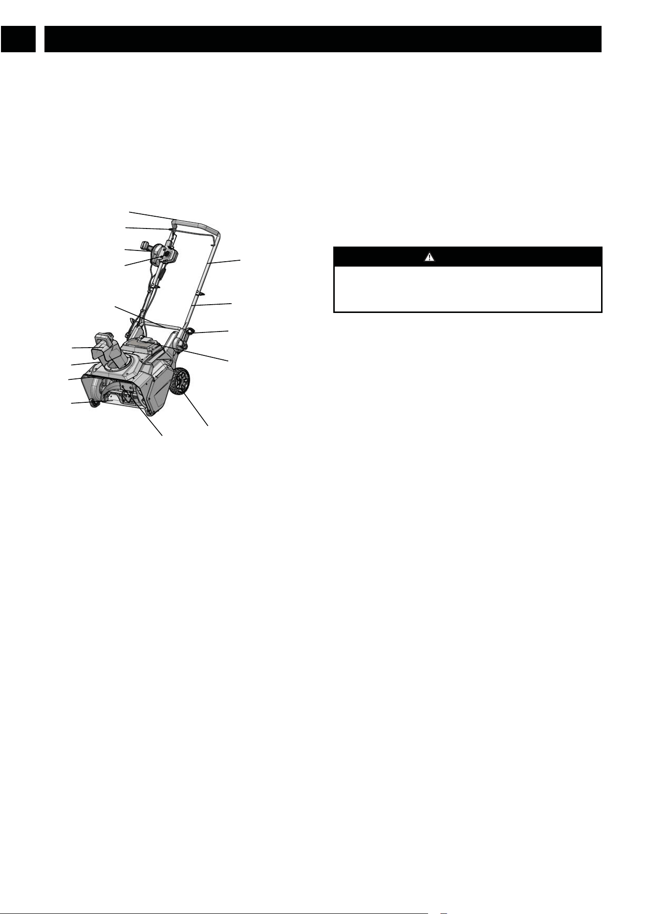
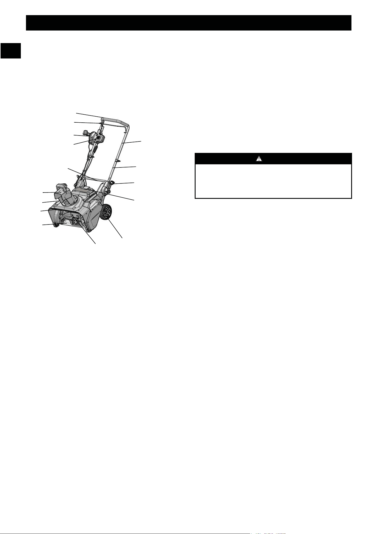
1.2 OVERVIEW
1
Handle bar
2
Bail lever
3
Safety switch button
4
Chute control rod
5
Battery door
6
Chute deflector
7
Discharge chute
8
LED lights
9
Scraper
10
Impeller
11
Wheel
12
Quick-release lever
13
Lower handle
14
Upper handle
15
Middle handle
16
Knob
17
Bolt
18
Screw
19
Nut
20
Battery pack
21
Battery release button
22
Trigger
23
Chute-rotation box
24
Switch box
25
Slot
26
Groove
27
Side wear pad
28
Belt
29
Pulley
30
Skid plates
31
Spacer
32
Cam lock
2 GENERAL POWER TOOL
SAFETY WARNINGS
WARNING
Read all safety warnings and all instructions. Failure to
follow the warnings and instructions may result in electric
shock, fire and/or serious injury.
Save all warnings and instructions for future reference.
The term “power tool” in the warnings refers to your mains-
operated (cordless) power tool.
2.1 TRAINING
• Do not allow children under the age of 14 to operate this
tool. Children who are 14 years of age or older must read
and understand the operating instructions and safety rules
in this manual and must be trained and supervised by a
parent.
• Read the operating and service instruction manual
carefully. Be thoroughly familiar with the controls and
the proper use of the power tool. Know how to stop the
unit and disengage the controls quickly.
• Never allow children to operate the power tool. Never
allow adults to operate the power tool without proper
instruction.
• Keep the area of operation clear of all persons,
particularly small children, and pets.
• Exercise caution to avoid slipping or falling, especially
when operating in reverse.
• Do not use on graveled surface unless the snow thrower is
adjusted for such a surface in accordance with the
operator’s manual.
• Dress Properly – Do not wear loose clothing or jewelry.
They can be caught in moving parts.
• Wear appropriate boots when operating the snow thrower.
• Operation of the snow thrower in the hand-held position
is unsafe, except in accordance with the special
instructions for such use provided in the operator’s
manual.
• Avoid Accidental Starting– Don't carry the snow thrower
with fingers on the switch while the battery is inserted.
Be sure the switch is off when inserting the battery pack.
4
English
EN

2.2 PREPARATION
• Thoroughly inspect the area where the power tool is to be
used and remove all doormats, sleds, boards, wires, and
other foreign objects.
• Do not operate the power tool without wearing adequate
winter garments. Wear footwear, which will improve
footing on slippery surfaces.
• Adjust the housing height to clear gravel or crushed rock
surface.
• Never attempt to make any adjustments while the
machine is running (except where specifically
recommended by manufacturer).
• Always wear safety glasses or eye shields during
operation or while performing an adjustment or repair to
protect eyes from foreign objects that may be thrown
from the machine.
• Prevent unintentional starting. Ensure the switch is in the
off-position before connecting to battery pack, picking up
or carrying the appliance. Carrying the appliance with
your finger on the switch or energizing appliance that
have the switch on invites accidents.
• Disconnect the battery pack from the appliance before
making any adjustments, changing accessories, or storing
appliance. Such preventive safety measures reduce the
risk of starting the appliance accidentally.
• When battery pack is not in use, keep it away from other
metal objects,like paper clips, coins, keys, nails, screw or
other small metal objects, that can make a connection
from one terminal to another. Shorting the battery
terminals together may cause burns or a fire.
2.3 OPERATION
• Do not put hands or feet near or under rotating parts.
Keep clear of the discharge opening at all times.
• Exercise extreme caution when operating on or crossing
gravel drives, walks, or roads. Stay alert for hidden
hazards or traffic.
• After striking a foreign object, turn the machine off and
remove the battery pack, and then inspect it for damage.
Repair any damage before restarting and using the
machine.
• If the power tool should start to vibrate abnormally, stop
the machine and check immediately for the cause.
Vibration is generally a warning of trouble.
• Stop the machine whenever you leave the operating
position, before unclogging the collector/impeller housing
or discharge guide, and when making any repairs,
adjustments, or inspections.
• When cleaning, repairing, or inspecting, make certain the
collector/impeller and all moving parts have stopped.
• Exercise extreme caution when operating on slopes.
• Never operate the snow thrower without proper guards,
keep other safety protective devices in place and working.
• Never direct the discharge toward people or areas where
property damage can occur. Keep children and others
away.
• Don’t Overreach – Keep proper footing and balance at all
times.
• Do not overload the machine capacity by attempting to
clear snow at too fast a rate.
• Don’t Force Snow Thrower – It will perform better and
safer at the rate for which it was designed.
• Never operate the power tool at high transport speeds on
slippery surfaces. Use care when reversing.
• Never direct discharge at bystanders or allow anyone in
front of the power tool.
• Disengage power to the collector/impeller when the
power tool is transported or not in use.
• Use only attachments and accessories approved by the
manufacturer of the snow thrower (such as wheel
weights, counterweights, or cabs).
• Never operate the power tool without good visibility or
light. Always be sure of your footing, and keep a firm
hold on the handles.
• Walk, never run.
• Clearing a Clogged Discharge Chute. Hand contact with the
rotating impeller inside the discharge chute is the most
common cause of injury associated with snow throwers.
Never use your hand to clean out the discharge chute.
To clear the chute:
1. SHUT THE ENGINE㸦Motor㸧 OFF!
2. Wait 10 seconds to be sure the impeller blades have
stopped rotating.
3. Always use a clean-out tool, not your hands.
• If the snow thrower strikes a foreign object follow these
steps:
1. Stop snow thrower. Release the switch.
2. Remove the battery pack.
3. Inspect for damage.
4. Repair any damage before restarting and operating
the snow thrower.
2.4 MAINTENANCE
• Check shear bolts; engine-mounted bolt, etc., at frequent
intervals for proper tightness to be sure the power tool is
in safe working condition.
• Always refer to owner’s guide instructions for important
details if the power tool is to be stored for an extended
period.
• Store Idle Snow throwers Indoors – When not in use,
snow throwers should be stored indoors in a dry, locked-
up place – out of reach of children.
• Store Idle Snow throwers Indoors – When not in use,
snow throwers should be stored indoors in a dry, locked-
up place – out of reach of children.
• Run the power tool a few minutes after throwing snow to
prevent freeze-up of the collector/impeller.
• Do not use a battery pack or appliance that is damaged or
modified. Damaged or modified batteries may exhibit
unpredictable behavior resulting in fire㸪explosion or
risk of injury.
5
English
EN
• Do not expose a battery pack or appliance to fire or
excessive emperature space. Exposure to fire or
temperature above 265°F (130°C) may cause explosion.
• Follow all charging instructions and do not charge the
battery pack or appliance outside of the temperature range
specified in the instructions. Charging improperly or at
temperatures outside of the specified range may damage
the battery and increase the risk of fire.
• Have servicing performed by a qualified repair person
using only identical replacement parts. This will ensure
that the safety of the product is maintained.
• Do not modify or attempt to repair the appliance or the
battery pack (as applicable) except as indicated in the
instructions for use and care.
• Maintain Snow Thrower With Care – Follow instructions
for lubricating and changing accessories.
3 PROPOSITION 65
WARNING
This product contains a chemical known to the state of
California to cause cancer, birth defects or other
reproductive harm. Some dust created by power sanding,
sawing, grinding, drilling, and other construction activities
contains chemicals known to cause cancer, birth defects or
other reproductive harm. Some examples of these chemicals
are:
• Lead from lead-based paints;
• Crystalline silica from bricks and cement and other
masonry products;
• Arsenic and chromium from chemically treated lumber.
Your risk of exposure to these chemicals varies depending
on how often you do this type of work. To reduce your
exposure to these chemicals, work in a well-ventilated area,
and work with approved safety equipment, such as dust
masks that are specially designed to filter out microscopic
particles.
Save these instructions.
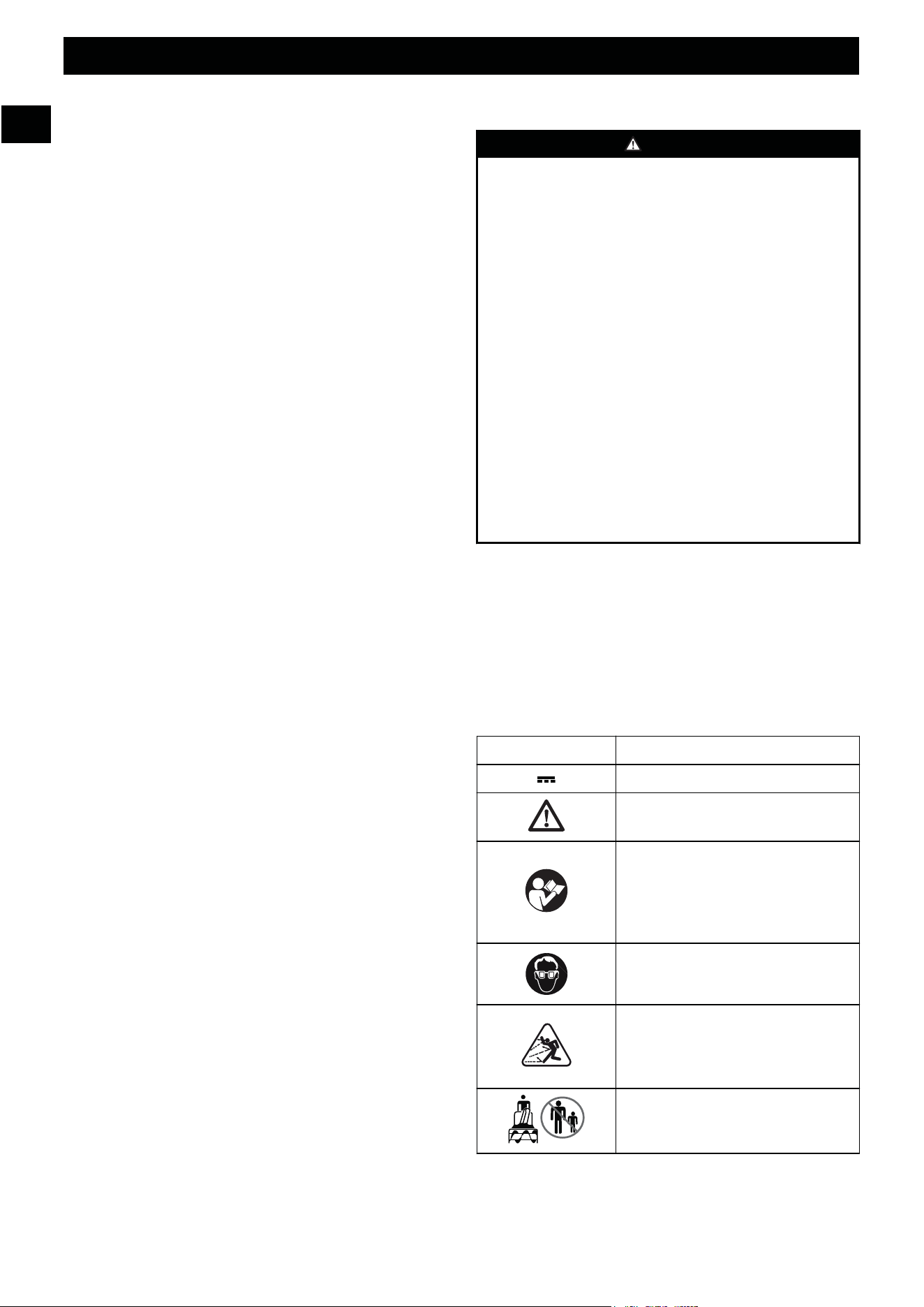
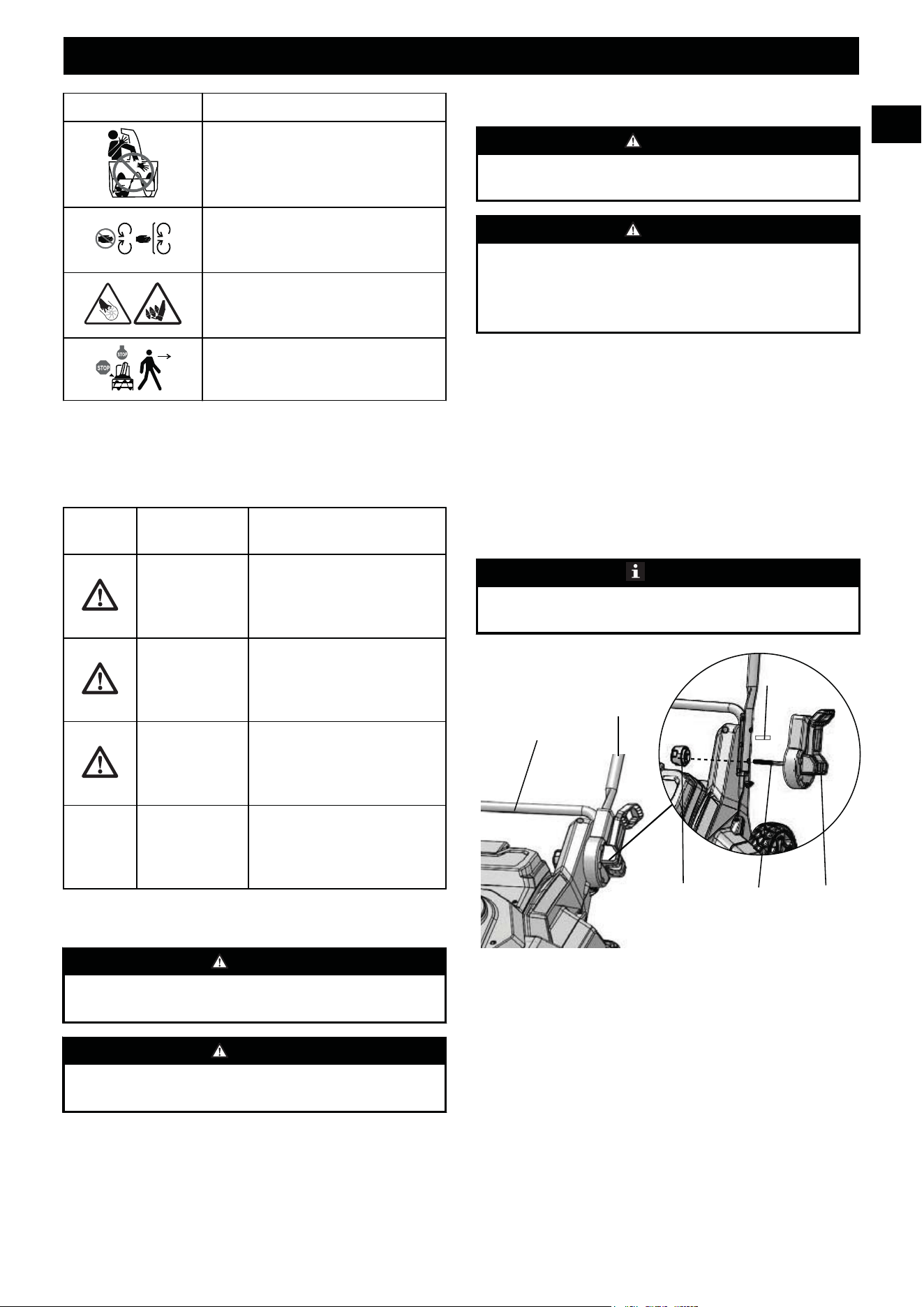
4 SYMBOLS ON THE PRODUCT
Some of the following symbols may be used on this tool.
Please study them and learn their meaning. Proper
interpretation of these symbols will allow you to operate the
tool better and safer.
Symbol Explanation
Direct current
Precautions that involve your safety.
Read and understand all instructions
before operating the product, and fol-
low all warnings and safety instruc-
tions.
Symbol Explanation
Wear eye protection.
Thrown objects can ricochet and re-
sult in personal injury or property
damage. Wear protective clothing and
boots.
Keep bystanders a safe distance from
the machine.
Keep hands away from the discharge
area.
Stay away from moving parts. Keep
all guards and shields in place.
Keep feet out of impeller. Keep feet
away from rotating impeller.
Stop the motor and remove the bat-
tery before leaving the product.
5 RISK LEVELS
The following signal words and meanings are intended to
explain the levels of risk associated with this product.
SYMBOL SIGNAL MEANING
DANGER Indicates an imminently haz-
ardous situation,which, if not
avoided, will result in death
or serious injury.
WARNING Indicates a potentially hazard-
ous situation,which, if not
avoided, could result in death
or serious injury.
CAUTION Indicates a potentially hazard-
ous situation, which, if not
avoided, may result in minor
or moderate injury.
CAUTION (Without Safety Alert Sym-
bol) Indicates a situation that
may result in property dam-
age.
6 INSTALLATION
WARNING
Do not change or make accessories that are not
recommended by the manufacturer.
6
English
EN
WARNING
Do not connect to power supply until you assemble all the
parts.
6.1 UNPACK THE MACHINE
WARNING
Make sure that you correctly assemble the machine before
use.
WARNING
• If the parts are damaged, do not use the machine.
• If you do not have all the parts, do not operate the
machine.
• If the parts are damaged or missing, speak to the service
center.
1. Open the package.
2. Read the documentation in the box.
3. Remove all the unassembled parts from the box.
4. Remove the machine from the box.
5. Discard the box and package in compliance with local
regulations.
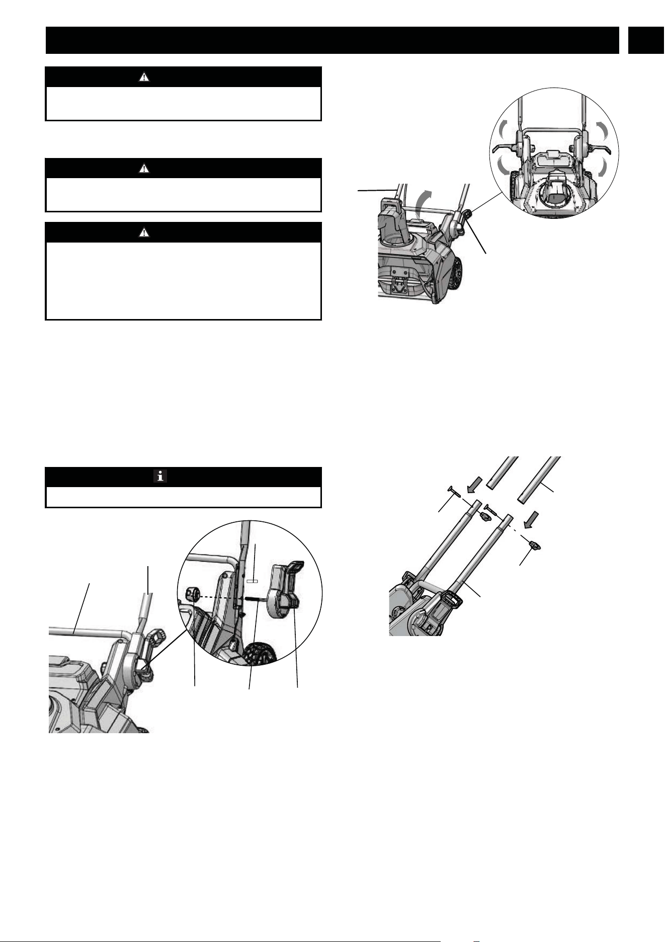
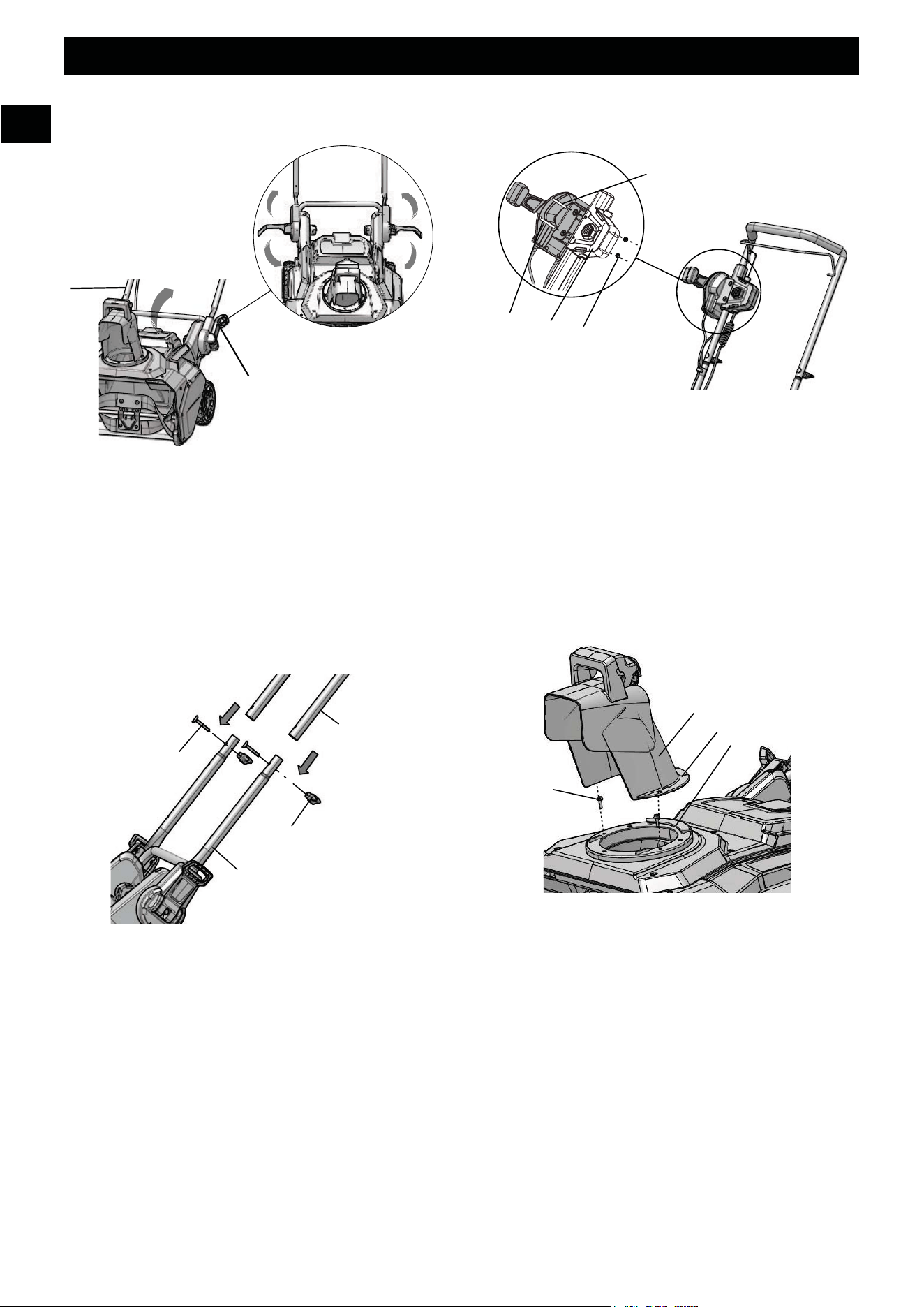
6.2 CAM LOCK ASSEMBLY
NOTE
Do not tighten the knob until the cam lock is in place.
1. Remove the knob (16) and spacer (31) from the cam lock
(32).
2. Insert the bolt (17) through the lower handle housing.
3. Slide the spacer (31) over the bolt (17).
4. Screw on the knob (16).
5. Fold the cam lock (32) to lock the handle into place.
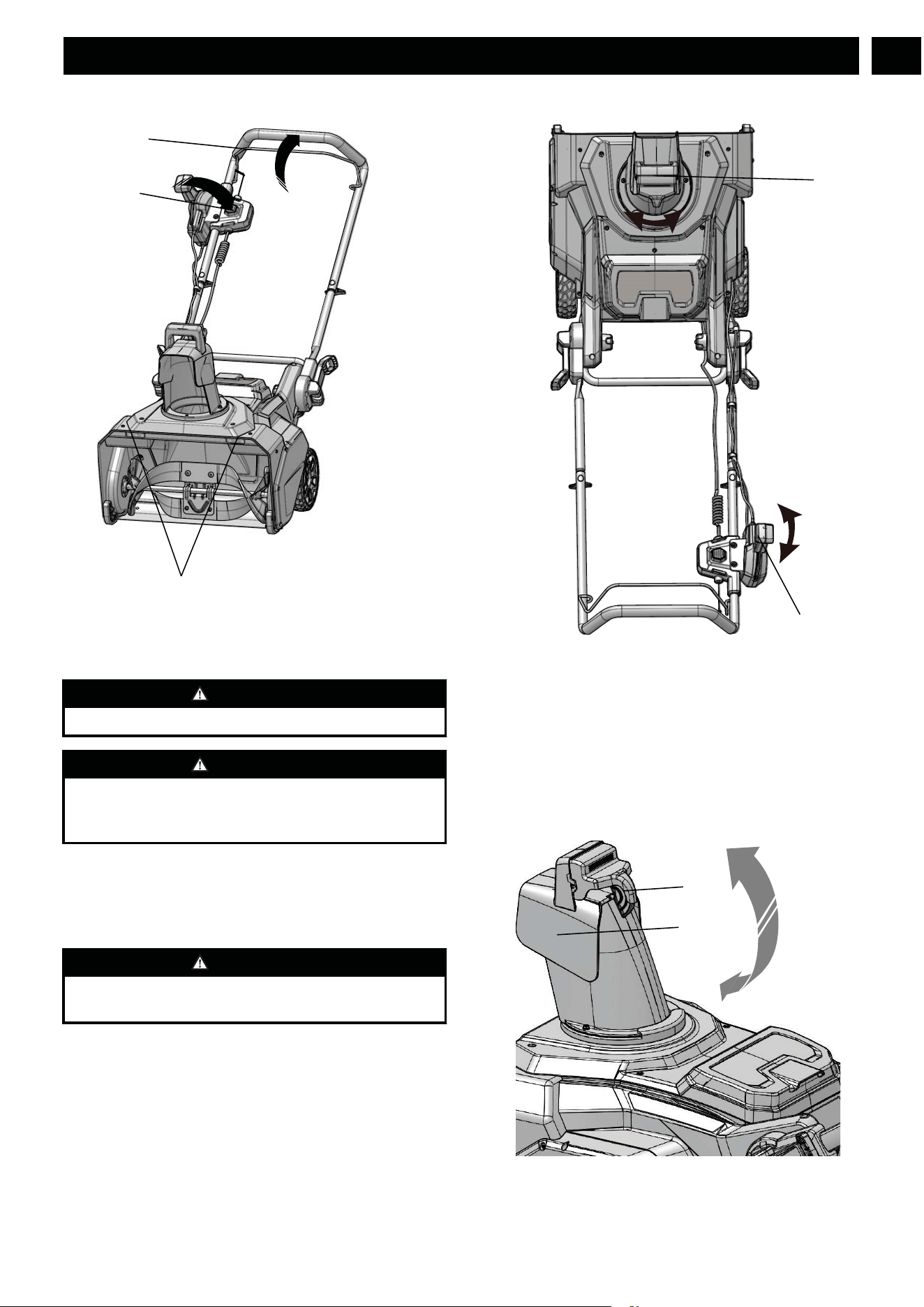
6.3 UNFOLD THE MIDDLE HANDLE
1. Open the quick-release levers (12) on the two sides of the
middle handle (15).
2. Unfold the middle handle (15) until they come to a stop.
3. Close the quick-release levers (12).
4. Tighten the knobs (16) to hold the middle handle (15) in
position.
6.4 INSTALL THE UPPER HANDLE
1. Align the holes in the middle handle (15) and the upper
handle (14).
2. Put the bolts (17) through the holes.
3. Tighten the handle knobs (16) onto the bolts (17).
4. Do the same operation on the other side.
7
English
EN
13
15
16
17
32
31
15
12
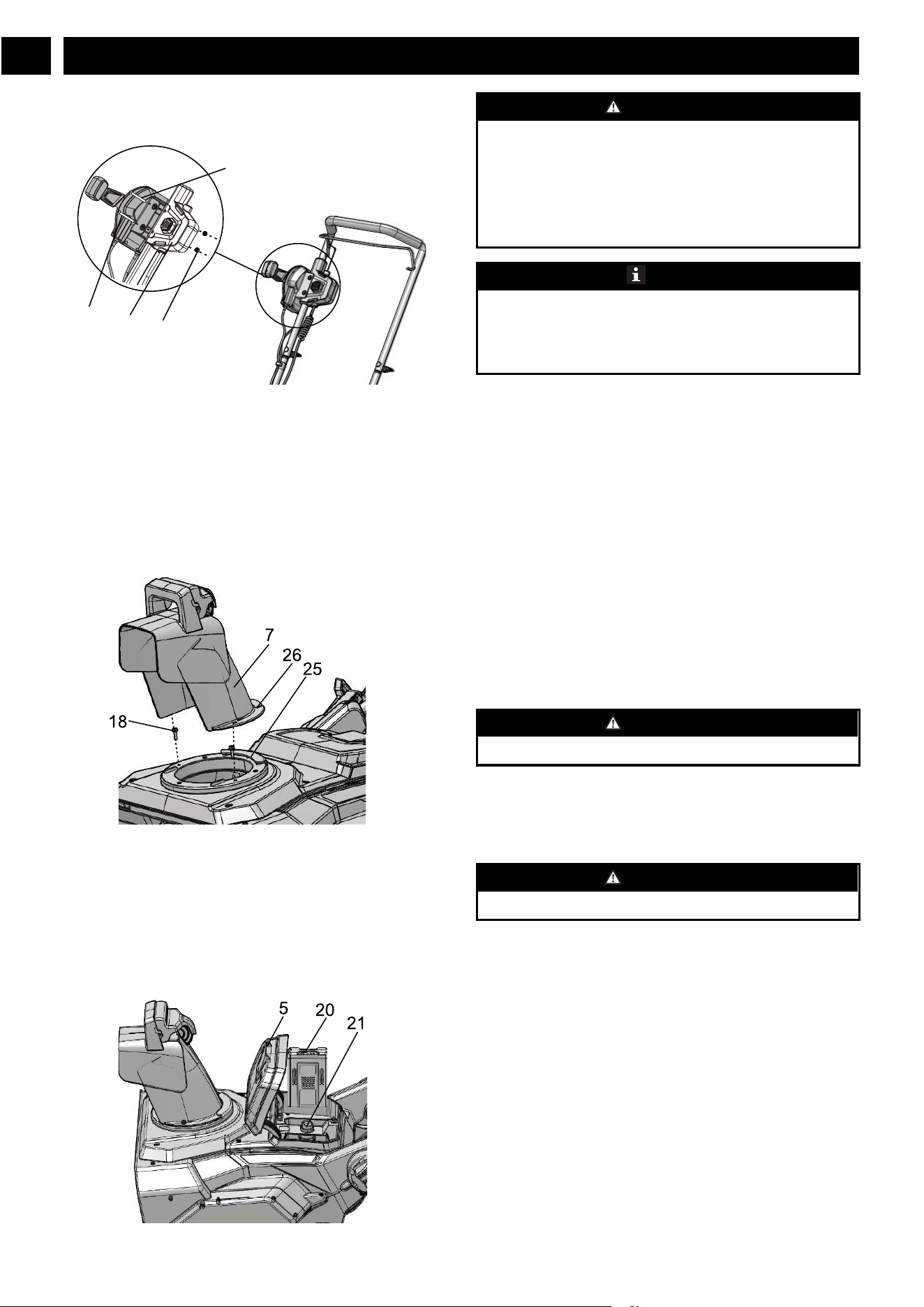
6.5 INSTALL THE CHUTE-ROTATION
BOX
1. Align the holes in the panel of the chute-rotation box (23)
and the switch box (24).
2. Put the chute-rotation box screws (18) through the holes.
3. Tighten the chute-rotation box screw nuts (19) with
Phillips Head screwdriver (not included).
6.6 INSTALL THE CHUTE
DEFLECTOR
1. Align the grooves (26) of the discharge chute with the
slot (25) on the chute housing.
2. Push the discharge chute (7) into position.
3. Tighten the discharge chute screws (18) with a Phillips
head screw driver to lock the discharge chute.
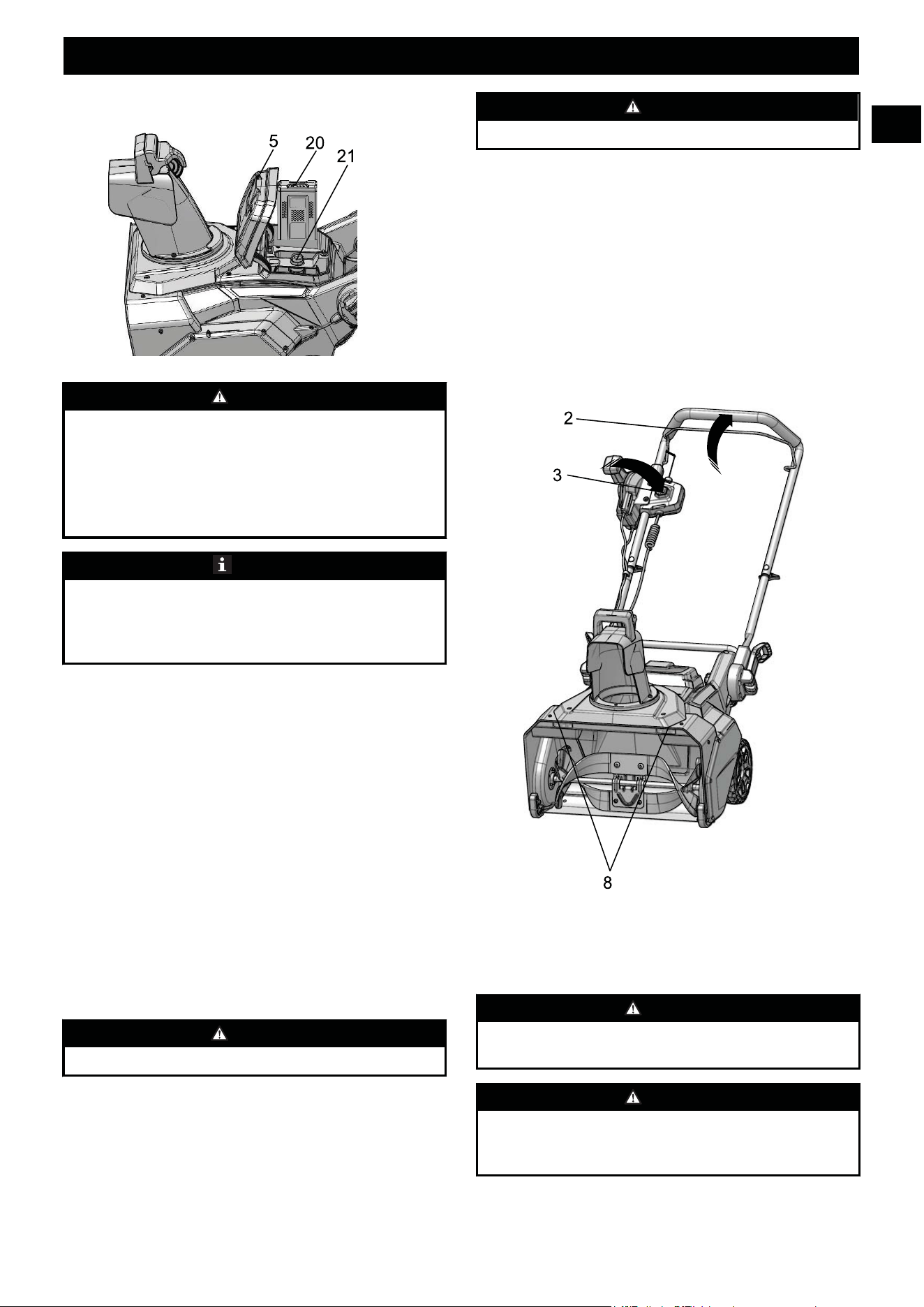
6.7 INSTALL THE BATTERY PACK
WARNING
• If the battery pack or charger is damaged, replace the
battery pack or the charger.
• Stop the machine and wait until the engine stops before
you install or remove the battery pack.
• Read, know, and follow the instructions in the battery
and charger manual.
NOTE
This machine has the dual-pack switch function that lets the
other battery pack continue to operate when the first one is
out of battery after 2-3 seconds. The machine can be
increased the double working time by the function.
1. Open the battery door (5).
2. Align the ribs on the battery pack (20) with the grooves in
the battery compartment.
3. Push the battery pack (20) into the battery compartment
until the battery pack (20) locks into place.
4. When you hear a click, the battery pack (20) is installed.
5. Close the battery door (5).
6.8 REMOVE THE BATTERY PACK
1. Open the battery door (5).
2. Push and hold the battery release button (21).
3. Remove the battery pack (20) from the machine.
7 OPERATION
WARNING
Wear eye protection during operation.
7.1 COLD WEATHER OPERATION
The safe battery operation temperature ranges from
6.8˚F (-14°C) ~ 113 ˚F (45˚C).
WARNING
Do not store or charge battery outside.
Battery must be charged and stored indoors prior to use of the
machine.
If the machine does not start below 1°F (-17°C),
• remove the battery pack from the machine,
• charge the battery pack for 10 minutes in warm area, or
when the charging light turns green.
• Install the battery pack again.
8
English
EN
18
23
24
19
7.2 START THE MACHINE
1. While holding the safety switch button (3), pull the bail
lever (2) to start the machine.
2. At the same time, the LED lights (8) can be turned on.
WARNING
Keep bystanders a safe distance from the machine.
WARNING
Examine the work area. Remove all stones, sticks, wire,
bones, and other debris that can ricochet because of the
rotating impeller.
7.3 STOP THE MACHINE
1. Release the bail lever (2) to stop the machine.
2. At the same time, the LED lights (8) can be turned off.
WARNING
Wait until the impeller fully stops before you start the
machine again. Do not quickly turn the machine off and on.
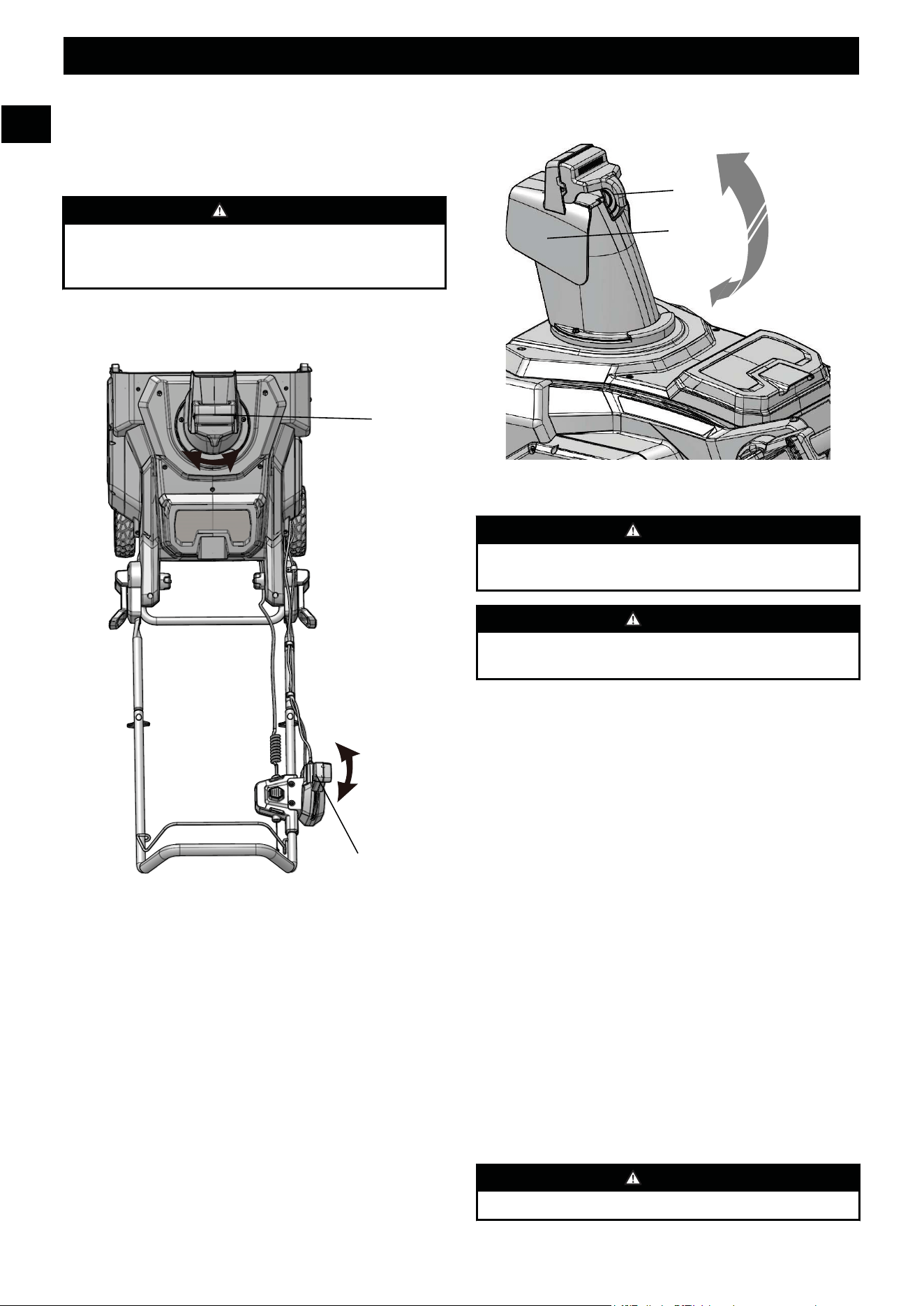
7.4 ADJUST THE DISCHARGE CHUTE
You can adjust the discharge chute 180° to change the snow
direction.
1. Push the chute-rotation handle (4) forward to move the
discharge chute (7) to the left.
2. Push the chute-rotation handle (4) rearward to move the
discharge chute (7) to the right.
7.5 ADJUST THE CHUTE DEFLECTOR
You can adjust the chute deflector up and down to change the
throwing distance of the snow.
9
English
EN
WARNING
Release the bail switch before you adjust the chute
deflector.
WARNING
Do not push the deflector so far forward that a gap shows
between the deflector and the chute.
1. Push and hold the trigger (22) on the chute deflector (6).
2. Move the chute deflector (6) up to increase the snow
distance.
3. Move the chute deflector (6) down to decrease the snow
distance.
7.6 OPERATION TIPS
• If it is possible, clear the snow with the direction of the
wind.
• In strong winds, lower the chute deflector to direct the
snow to the ground.
• When you complete the work, let the machine operate for
a while to prevent ice formation in the discharge chute.
• If the snow is deeper than 8", decrease the speed and let
the machine work at its own pace.
• Do not use the scraper to remove compact snow and ice.
8 MAINTENANCE
WARNING
Disconnect the extension cord before maintenance.
CAUTION
Use only approved replacement parts.
CAUTION
Do not use strong solvents or detergents on the plastic
housing or components.
8.1 GENERAL MAINTENANCE
• Before each use, examine the machine for damaged,
missing, or loose parts such as screws, nuts, bolts and
caps.
• Tighten correctly all the fasteners and caps.
• Clean the remaining snow on the machine with a brush.
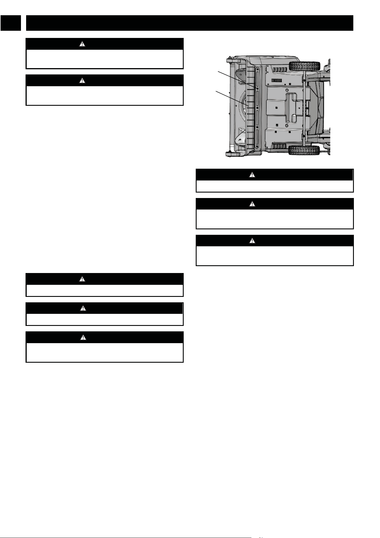
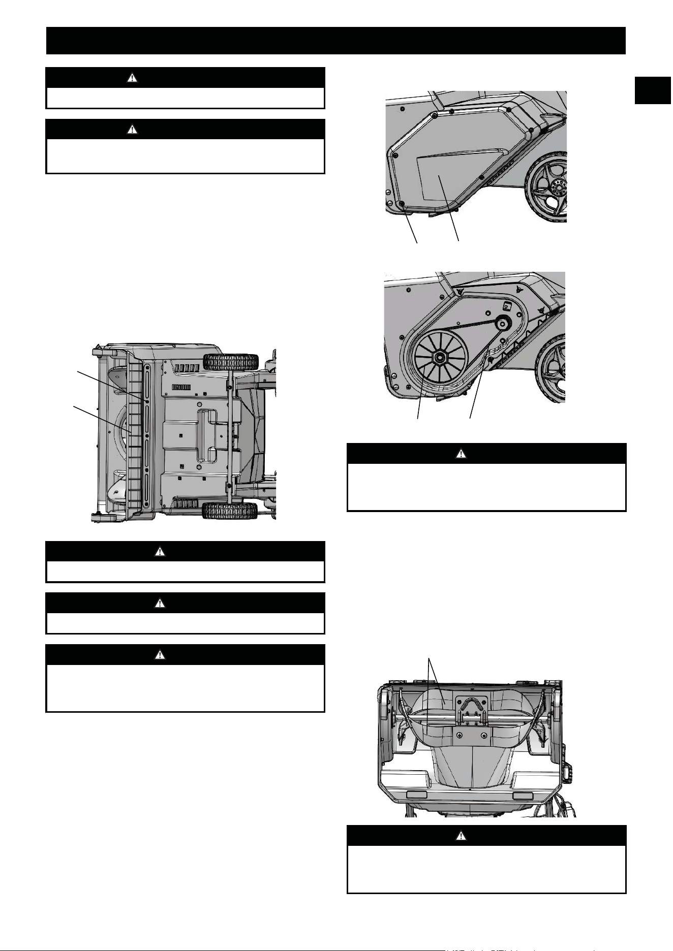
8.2 REPLACE THE SCRAPER
WARNING
Use only approved replacement scrapers.
WARNING
Wear heavy gloves around the blade when you touch the
blade.
WARNING
The scraper is located at the bottom of the impeller housing.
Ensure that the battery is not installed in the tool.
1. Turn the machine to its side.
2. Remove the 5 bolts (17) below the deck that attach the
scraper (9) to the machine.
3. Remove the worn scraper (9) from the machine.
4. Install the new scraper (9).
5. Install and tighten the bolts (17) that you removed.
10
English
EN
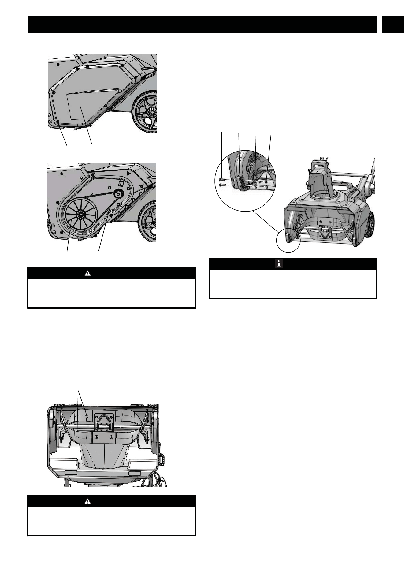
8.3 REPLACE THE BELT
WARNING
Make sure to turn off the bail lever and remove the battery
pack(s) before performing any maintenance task on your
snow thrower.
1. Remove the screws (18) on the side wear pad (27).
2. Turn the large pulley (29) counterclockwise while you
remove the remaining belt (28).
3. Turn the new belt (28) onto the pulleys (29).
4. Install and tighten the screws (18) that you removed.
8.4 REPLACE THE IMPELLER
WARNING
Make sure to turn off the bail lever and remove the battery
pack(s) before performing any maintenance task on your
snow thrower.
1. Remove the 4 sets of nuts and bolts on the middle steel
plate.
2. Remove the 4 sets of nuts and bolts on each side.
3. Remove the impellers (10).
4. Install the new impellers (10).
5. Tigthen the 8 sets of nuts and bolts that you removed.
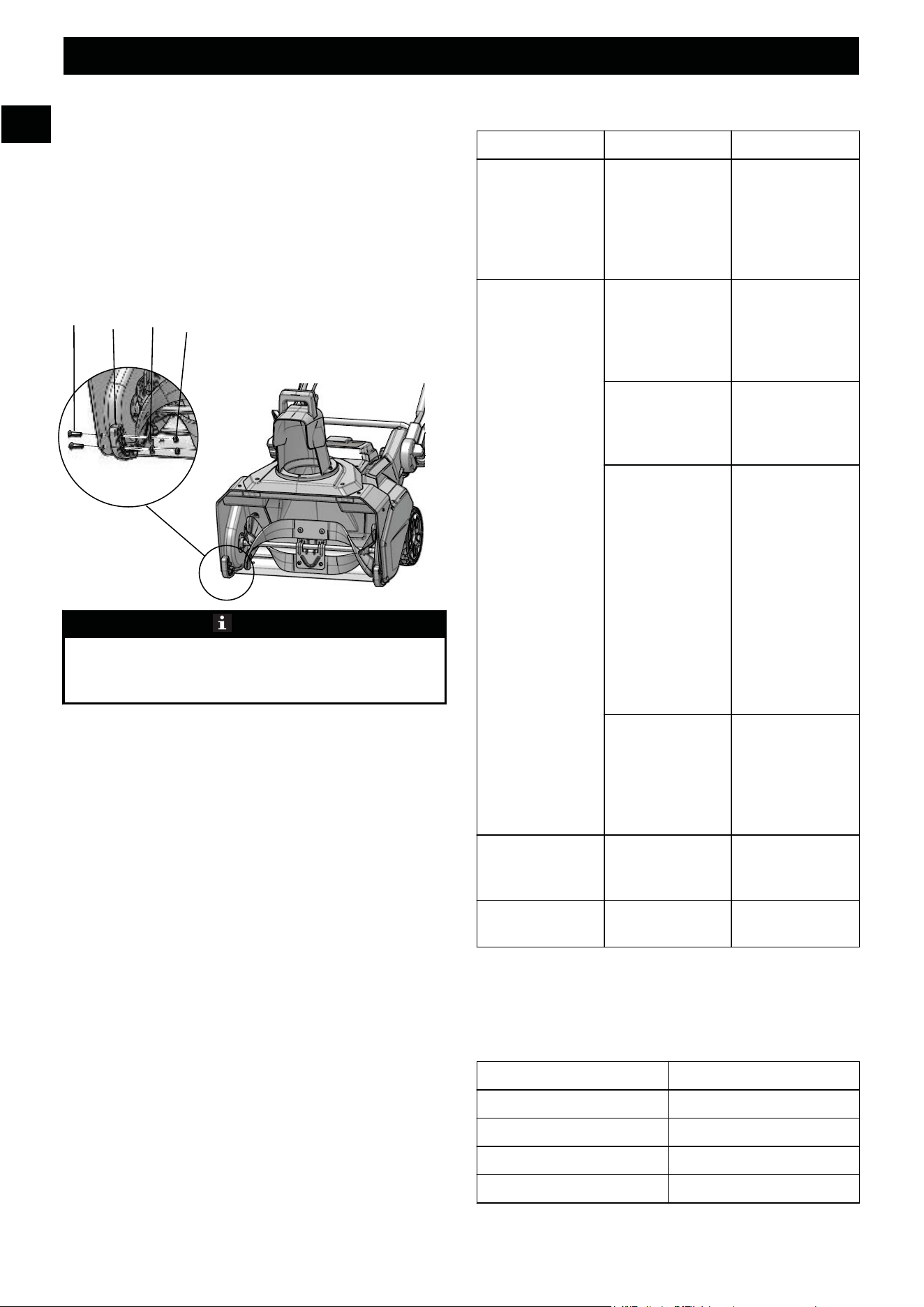
8.5 REPLACE THE SKID PLATES
NOTE
The range of adjustable height for skid plates is 1.5mm,
when putting the bolts through the U-hole on the skid
plates.
1. Loosen the 2 sets of bolts (17), spacers (31) and nuts (19)
that attach the skid plates (30) to the snow thrower
housing.
2. Remove the skid plates (30).
3. Install the new skid plates (30).
4. Do the same operation on the other side.
8.6 STORE THE MACHINE
• Clean the machine before storage.
• Make sure the motor is not hot when you store the
machine.
• Make sure that the machine does not have loose or
damaged parts. If it is necessary, do these steps/
instructions:
• Replace the damaged parts.
• Tighten the bolts.
• Speak to a person at an approved service center.
• Store the machine in a dry area.
• Make sure that children cannot come near the machine.
11
English
EN
9 TROUBLESHOOTING
Problem Possible cause Solution
The handle is not
in position.
The bolts are not
engaged correctly.
Adjust the height
of the handle and
make sure that the
knobs and bolts
are aligned cor-
rectly.
The machine does
not start.
The battery is not
charged.
Charge the battery
by following the
procedures in the
battery and charg-
er manual.
The switch is de-
fective.
Have the switch
replaced by an au-
thorized service
center.
Battery is too cold. Remove battery
from snow throw-
er. Place battery on
charger and allow
to charge for 10
minutes or until
the changing light
turns green. Re-
move from charger
and install in snow
thrower for use.
Battery may re-
quire service or re-
placement.
Call toll free help-
line, at
1-855-345-3934 or
replace battery.
The engine is on,
but the impeller
does not turn.
The belt is dam-
aged.
Replace the belt.
A thin layer of
snow stays behind.
The scraper is
damaged.
Replace the scra-
per.
* If you cannot find the solution to these problems, call
1-855-345-3934 .
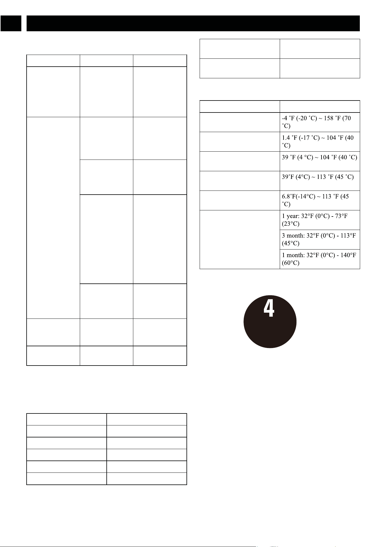
10 TECHNICAL DATA
Voltage 60 V
No load speed 1800 RPM
Clearing width 22 in
Clearing depth 13 in
Impeller size 18 in
Weight (without battery pack) 56.9 lbs (25.8 kg)
Battery LB604 and other BAC
Series
Charger CAC801 and other CAC
Series
The recommended ambient temperature range:
erutarepmeTmetI
Snow Thrower storage tem-
perature range
Snow Thrower operation
temperature range
Battery charging temperature
range
Charger operation tempera-
ture range
Battery discharging tempera-
ture range
Battery storage temperature
range
11 LIMITED WARRANTY
Greenworks hereby warranties this product, to the original
purchaser with proof of purchase, for a period of four (4)
years against defects in materials, parts or workmanship.
Greenworks, at its own discretion will repair or replace any
and all parts found to be defective, through normal use, free
of charge to the customer. This warranty is valid only for
units which have been used for personal use that have not
been hired or rented for industrial/commercial use, and that
have been maintained in accordance with the instructions in
the owners’ manual supplied with the product from new.
ITEMS NOT COVERED BY WARRANTY:
1. Any part that has become inoperative due to misuse,
commercial use, abuse, neglect, accident, improper
maintenance, or alteration; or
12
English
EN
TOOL WARRANTY
YEAR/AÑOS
GARANTÍA DE LA
HERRAMIENTA

2. The unit, if it has not been operated and/or maintained in
accordance with the owner's manual; or
3. Normal wear, except as noted below;
4. Routine maintenance items such as lubricants, blade
sharpening;
5. Normal deterioration of the exterior finish due to use or
exposure.
HELPLINE:
Warranty service is available by calling our toll-free helpline,
at 1-855-345-3934 .
TRANSPORTATION CHARGES:
Transportation charges for the movement of any power
equipment unit or attachment are the responsibility of the
purchaser. It is the purchaser’s responsibility to pay
transportation charges for any part submitted for replacement
under this warranty unless such return is requested in writing
by Greenworks.
13
English
EN
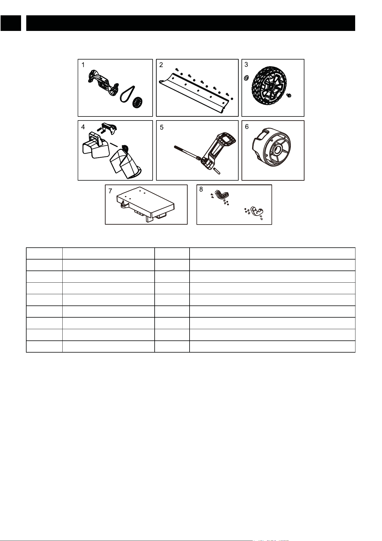
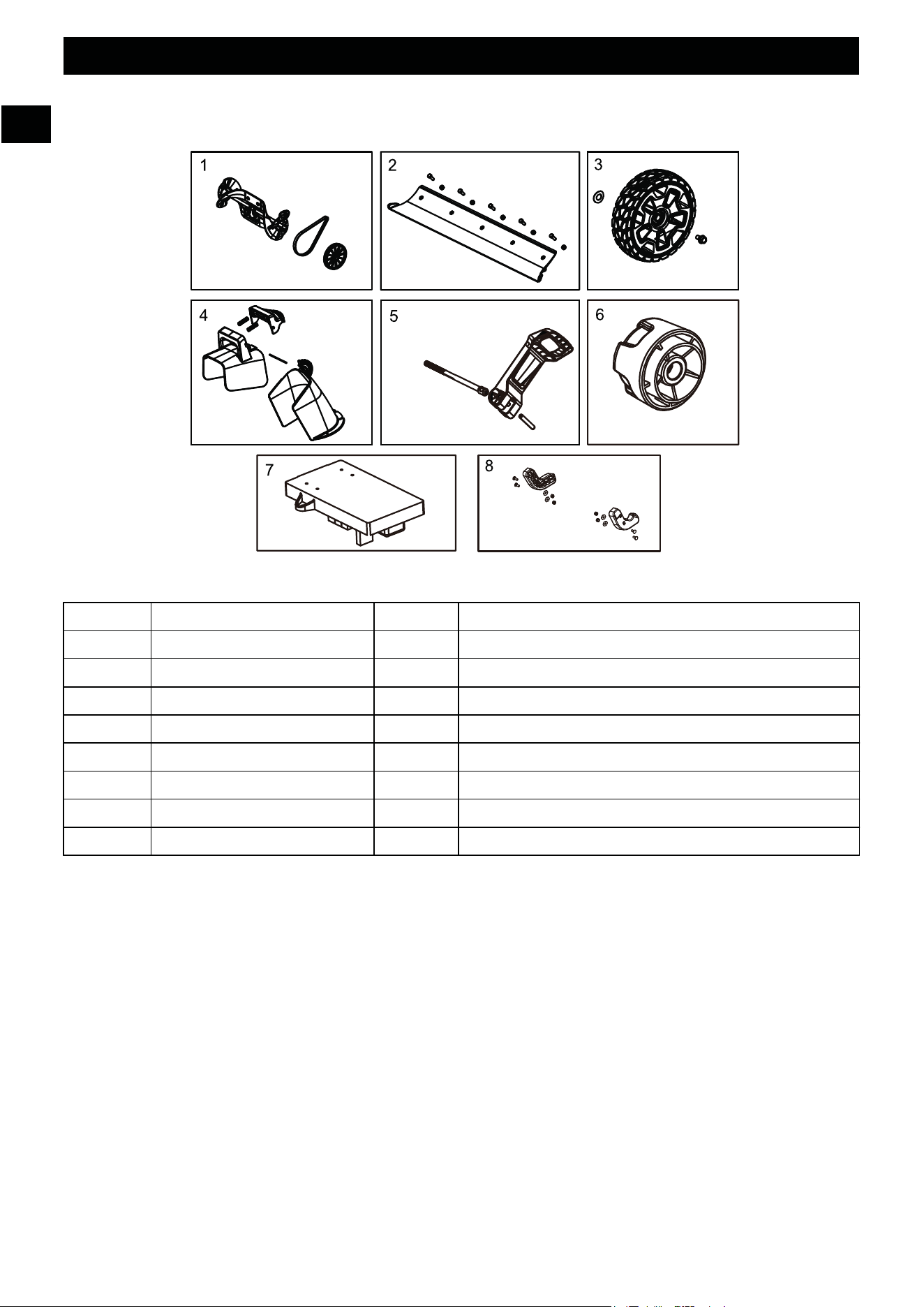
7 R0200887-00 1 PCB board
8 R0200655-00 1 Skid plates
Greenworks Tools
PO Box 1238
Mooresville, NC 28115
14
English
EN
12 EXPLODED VIEW
noitpircseDytQ.oN traP.oN
1 R0200649-00 1 Impeller assembly
2 R0200650-00 1 Scraper Kit
3 R0200648-00 1 Wheel Assembly
4 R0200651-00 1 Chute Deflector Assembly
5 R0200652-00 1 Quick-Release Lever Assembly
6 R0200653-00 1 Knob

#$#%%
&+<=#>?$
=#@
&<#>+
J=##
X##
! "#$
% &
'&
Z+[$\%$]^J#
_+$=#@%$=#]<#%
Z+<$#?J$#\=$
_+$=#@%$++J<#
_+$=#@%$=\%=#@%$
=%J=
_+$=#@%$%`$=%$=%J=
_+$=#@%$[{
|#%%$[{
( )
J=##=%#=#+%`{
&J+=%$]^J#
Z=#@%$]^J#
}\J+%$=%J=%%+=?
}\J+%$%`$=%$=%J=
+\+%`J=##
*
X##?$
~J+#J=#@%$+=%
~J+#J=#@%$=
~J+#J=#@%$
~J+#J=#@%$+<$=+%<==#@%
[\+
}$=#%$]^J#
& "$ !
+ !
/#
;<
=>
="
1 DESCRIPCIÓN
1.1 FINALIDAD
Esta máquina se utiliza para quitar y despejar la nieve de
aceras, jardines, calzadas y otras superficies a nivel del suelo.
1.2 PERSPECTIVA GENERAL
1
Manillar
2
Palanca de seguridad
3
Botón del interruptor de seguridad
4
Varilla de control del conducto
5
Puerta de la batería
6
Deflector del conducto
7
Conducto de descarga
8
Luces LED
9
Rascador
10
Rotor
11
Rueda
12
Palanca de apertura rápida
13
Asa inferior
14
Asa superior
15
Asa intermedia
16
Mando
17
Perno
18
Tornillo
19
Tuerca
20
Batería
21
Botón de desbloqueo de la batería
22
Gatillo
23
Caja de rotación del conducto
24
Caja de conexiones
25
Ranura
26
Ranura
27
Almohadilla de desgaste lateral
28
Correa
29
Polea
30
Placas de protección de bajos
31
Espaciador
32
Cierre rápido
2 ADVERTENCIAS GENERALES
DE SEGURIDAD PARA
HERRAMIENTAS
ELÉCTRICAS
AVISO
Lea todas las advertencias de seguridad y todas las
instrucciones. El incumplimiento de las advertencias e
instrucciones puede provocar descargas eléctricas,
incendios o lesiones graves.
Guarde todas las advertencias e instrucciones para su consulta
posterior.
El término "herramienta eléctrica" empleado en las
advertencias se refiere a su herramienta eléctrica con
funcionamiento de red (inalámbrica).
2.1 FORMACIÓN
• No permita que niños menores de 14 años utilicen esta
herramienta. Los niños de 14 años o mayores deben leer y
entender las instrucciones de funcionamiento y las
normas de seguridad que se encuentran en este manual y
deben recibir formación y supervisión por parte de uno de
sus progenitores.
• Lea detenidamente el manual de instrucciones de
funcionamiento y servicio. Familiarícese a fondo con los
controles y el uso correcto de la herramienta eléctrica.
Debe saber cómo detener la unidad y desacoplar los
controles rápidamente.
• Nunca permita que los niños utilicen la herramienta
eléctrica. Nunca permita que utilicen la herramienta
eléctrica adultos sin la debida instrucción.
• Mantenga la zona de funcionamiento libre de cualquier
persona, especialmente niños pequeños y mascotas.
• Tenga precaución para evitar resbalones o caídas,
especialmente durante la utilización marcha atrás.
• No utilice en superficies con grava a menos que el
quitanieves esté ajustado para tal superficie de acuerdo
con el manual del operario.
• Lleve indumentaria adecuada – No lleve ropa o joyas
sueltas. Pueden quedar atrapadas en las piezas móviles.
• Lleve botas adecuadas al utilizar el quitanieves.
• El funcionamiento del quitanieves en la posición de mano
no es seguro, excepto de acuerdo con las instrucciones
especiales para dicho uso que se proporcionan en el
manual del operario.
16
Español
ES

• Evite el arranque accidental – No transporte el
quitanieves con los dedos en el interruptor mientras esté
insertada la batería. Asegúrese de que el interruptor esté
desactivado al insertar la batería.
2.2 PREPARATIVOS
• Inspeccione exhaustivamente la superficie donde va a
utilizarse la herramienta eléctrica y elimine todos los
felpudos, trineos, planchas, cables y otros objetos
extraños.
• No utilice la herramienta eléctrica sin llevar indumentaria
adecuada de invierno. Lleve calzado, que mejorará el
equilibrio en superficies resbaladizas.
• Ajuste la altura de la carcasa para dejar espacio en caso
de superficies de grava o piedra triturada.
• Nunca intente realizar ningún ajuste mientras la máquina
esté en funcionamiento (excepto cuando el fabricante lo
recomiende específicamente).
• Lleve siempre gafas de seguridad o protectores oculares
durante la utilización o al realizar un ajuste o una
reparación para proteger los ojos de objetos extraños que
puedan ser lanzados desde la máquina.
• Evite el arranque accidental. Asegúrese de que el
interruptor esté en la posición de apagado antes de
conectar a la batería y al coger o transportar el aparato. El
transporte del aparato con el dedo en el interruptor o la
conexión de un aparato que tiene el interruptor activado
fomenta los accidentes.
• Desconecte la batería del aparato antes de realizar ajustes,
cambiar accesorios o almacenarlo. Estas medidas de
seguridad preventivas reducen el riesgo de que el aparato
se ponga en marcha accidentalmente.
• Cuando la batería no esté en uso, manténgala alejada de
otros objetos metálicos como clips, monedas, llaves,
clavos, tornillos u otros objetos metálicos pequeños que
puedan hacer una conexión entre los terminales. El
cortocircuito de los terminales de la batería puede
provocar quemaduras o un incendio.
2.3 FUNCIONAMIENTO
• No ponga las manos ni los pies cerca o debajo de las
piezas giratorias. Manténgase alejado en todo momento
de la abertura de descarga.
• Extreme las precauciones al trabajar sobre o al cruzar
senderos de grava, aceras o caminos. Esté alerta a los
riesgos ocultos o al tráfico.
• Después de golpear un objeto extraño, apague la máquina
y retire la batería, posteriormente inspecciónela para
detectar daños. Repare los daños antes de volver a poner
en marcha y utilizar la máquina.
• Si la herramienta eléctrica empieza a vibrar de manera
anormal, detenga la máquina y compruebe de inmediato
la causa. Normalmente la vibración es una advertencia de
problemas.
• Detenga la máquina cada vez que abandone la posición
de utilización, antes de desatascar la carcasa del colector/
rotor o la guía de descarga, así como al realizar
reparaciones, ajustes o inspecciones.
• Cuando limpie, repare o inspeccione, asegúrese de que el
colector/rotor y todas las piezas en movimiento se hayan
detenido.
• Extreme las precauciones cuando trabaje en pendientes.
• Nunca utilice el quitanieves sin las protecciones
adecuadas, mantenga los demás dispositivos de
protección de seguridad en su posición y en estado de
funcionamiento.
• Nunca dirija la descarga hacia personas o zonas donde
puedan producirse daños a la propiedad. Mantenga
alejados a los niños y otras personas.
• No se estire – Mantenga en todo momento una postura
adecuada y el equilibrio.
• No sobrecargue la capacidad de la máquina intentando
quitar demasiada nieve a una velocidad demasiado rápida.
• No fuerce el quitanieves – Hará el trabajo mejor y con
mayor seguridad a la velocidad para la que se diseñó.
• Nunca utilice la herramienta eléctrica a altas velocidades
de transporte en superficies resbaladizas. Tenga cuidado
al dar marcha atrás.
• Nunca dirija la descarga a los transeúntes ni permita que
una persona se ponga delante de la herramienta eléctrica.
• Desconecte la alimentación del colector/rotor cuando la
herramienta eléctrica se transporte o no esté en uso.
• Utilice únicamente accesorios aprobados por el fabricante
del quitanieves (como pesos de ruedas, contrapesos o
cabinas).
• Nunca utilice la herramienta eléctrica sin una buena
visibilidad o luz. Asegúrese siempre de tener una
posición estable y mantenga un agarre firme en las asas.
• Desobstrucción de un conducto de descarga. El contacto
manual con el rotor giratorio dentro del conducto de descarga
• Camine, no corra.
es la causa más común de lesiones asociadas con los
quitanieves. Nunca utilice la mano para limpiar el
conducto de descarga. Para desobstruir el conducto:
1. ¡APAGUE EL MOTOR!
2. Espere 10 segundos para asegurarse de que las palas
del rotor hayan dejado de girar.
3. Utilice siempre una herramienta de limpieza, no sus
manos.
• Si el quitanieves golpea un objeto extraño siga estos
pasos:
1. Detenga el quitanieves. Suelte el interruptor.
2. Retire la batería.
3. Inspeccione si hay daños.
4. Repare los daños antes de volver a poner en marcha y
utilizar el quitanieves.
2.4 MANTENIMIENTO
• Compruebe los pernos de seguridad, los pernos de
montaje del motor, etc., a intervalos frecuentes para
17
Español
ES
garantizar un apriete adecuado y que la herramienta
eléctrica esté en condiciones seguras de funcionamiento.
• Consulte siempre las instrucciones de la guía del
propietario para obtener detalles importantes si la
herramienta eléctrica debe almacenarse durante un
periodo prolongado.
• Almacene los quitanieves inactivos en interior – Cuando
no estén en uso, los quitanieves deben almacenarse en
interiores, en un lugar a seco, cerrado y fuera del alcance
de los niños.
• Almacene los quitanieves inactivos en interior – Cuando
no estén en uso, los quitanieves deben almacenarse en
interiores, en un lugar a seco, cerrado y fuera del alcance
de los niños.
• Haga funcionar la herramienta eléctrica unos minutos
después de quitar nieve para evitar la congelación del
colector/rotor.
• No utilice una batería o un aparato que haya sufrido
daños o modificaciones. Las baterías dañadas o
modificadas pueden exhibir un comportamiento
impredecible que puede dar lugar a un incendio, una
explosión o un riesgo de lesiones.
• No exponga una batería o un aparato al fuego ni a un
espacio con temperatura excesiva. La exposición al fuego
o a una temperatura superior a 265°F (130°C) puede
provocar una explosión.
• Siga todas las instrucciones de carga y no cargue la
batería o el aparato fuera del intervalo de temperatura
especificado en las instrucciones. La carga incorrecta o a
temperaturas fuera del intervalo especificado puede dañar
la batería y aumentar el riesgo de incendio.
• Solicite a un técnico de reparación cualificado que realice
las tareas de servicio utilizando únicamente piezas de
repuesto idénticas. Esto garantizará el mantenimiento de
la seguridad del producto.
• No modifique ni intente reparar el aparato o la batería
(según corresponda), excepto lo indicado en las
instrucciones de uso y cuidado.
• Mantenga los quitanieves con cuidado – Siga las
instrucciones para lubricar y cambiar los accesorios.
3 PROPUESTA 65
AVISO
Este producto contiene una sustancia química conocida en
el estado de California como causante de cáncer, defectos
de nacimiento u otros daños reproductivos. El polvo
generado por el lijado eléctrico, el serrado, el esmerilado, la
perforación y otras actividades de construcción contiene
sustancias químicas que se sabe que son causantes de
cáncer, defectos de nacimiento u otros daños reproductivos.
Algunos ejemplos de estas sustancias químicas son:
• Plomo de pinturas con base de plomo;
• Sílice cristalina de ladrillos y cemento y otros productos
de albañilería;
• Arsénico y cromo de la madera tratada químicamente.
El riesgo de exposición a estas sustancias químicas varía
según la frecuencia con la que realice este tipo de trabajo.
Para reducir su exposición a estas sustancias químicas,
trabaje en una zona bien ventilada y trabaje con equipos de
seguridad aprobados, como máscaras antipolvo, que estén
especialmente diseñadas para filtrar partículas
microscópicas.
Conserve estas instrucciones.
4 SÍMBOLOS EN EL PRODUCTO
En esta herramienta pueden utilizarse algunos de los
siguientes símbolos. Le rogamos que los estudie y aprenda su
significado. La interpretación correcta de estos símbolos le
permitirá manejar la herramienta mejor y de manera más
segura.
Símbolo Explicación
Corriente continua
Precauciones que afectan a su seguri-
dad.
Debe leer y entender todas las in-
strucciones antes de manejar el pro-
ducto, así como seguir todas las ad-
vertencias e instrucciones de seguri-
dad.
Lleve protección ocular.
Los objetos proyectados pueden re-
botar y provocar lesiones personales
o daños materiales. Lleve indumenta-
ria de protección y botas.
Mantenga a los transeúntes a una dis-
tancia segura de la máquina.
18
Español
ES
Símbolo Explicación
Mantenga las manos alejadas de la
zona de descarga.
Manténgase alejado de las piezas mó-
viles. Mantenga todas las protec-
ciones en su posición.
Mantenga los pies lejos del rotor.
Mantenga los pies y las manos aleja-
dos del rotor giratorio.
Detenga el motor y retire la batería
antes de dejar el producto.
5 NIVELES DE RIESGO
Las siguientes indicaciones y significados tienen como fin
explicar los niveles de riesgo asociados a este producto.
SÍMBOLO INDICACIÓN SIGNIFICADO
PELIGRO Indica una situación de peli-
gro inminente que, de no evi-
tarse, provocará lesiones
graves o incluso la muerte.
ADVERTEN-
CIA
Indica una situación de peli-
gro potencial que, de no evita-
rse, podría provocar lesiones
graves o incluso la muerte.
PRECAUCIÓN Indica una situación de peli-
gro potencial que, de no evita-
rse, puede provocar lesiones
leves o moderadas.
PRECAUCIÓN (Sin símbolo de alerta sobre
seguridad) Indica una situa-
ción que puede provocar da-
ños materiales.
6 INSTALACIÓN
AVISO
No cambie ni utilice accesorios que no sean los
recomendados por el fabricante.
AVISO
No conecte la fuente de alimentación hasta que haya
montado todas las piezas.
6.1 DESEMBALAJE DE LA MÁQUINA
AVISO
Asegúrese de montar correctamente la máquina antes del
uso.
AVISO
• Si las piezas presentan daños, no utilice la máquina.
• Si no tiene todas las piezas, no utilice la máquina.
• Si faltan piezas o hay piezas dañadas, hable con el
centro de servicio.
1. Abra el embalaje.
2. Lea la documentación que se encuentra en la caja.
3. Retire todas las piezas sin montar de la caja.
4. Retire la máquina de la caja.
5. Deseche la caja y el embalaje de conformidad con los
reglamentos locales.
6.2 INSTALACIÓN DEL CIERRE
RÁPIDO
NOTA
No apriete la perilla hasta que el cierre rápido esté en su
sitio.
1. Saque la perilla (16) y los espaciador (31) del cierre
rápido (32).
2. Inserte el perno (17) por la parte inferior del asidero.
3. Inserte los dos espaciador (31) en el perno (17).
4. Enrosque de nuevo la perilla (16).
5. Pliegue la palanca del cierre rápido (32) hacia dentro para
asegurar el asidero en su lugar.
19
Español
ES
13
15
16
17
32
31
6.3 DESPLIEGUE LA MANIJA
CENTRAL
1. Abra las palancas de liberación rápida (12) en los dos
lados de la manija central (15).
2. Despliegue la manija central (15) hasta que se detenga.
3. Cierre las palancas de liberación rápida (12).
4. Apriete las perillas (16) para sostener la manija central
(15) en su posición.
6.4 INSTALACIÓN DEL ASA
SUPERIOR
1. Alinee los orificios del asa intermedia (15) y el asa
superior (14).
2. Introduzca los pernos (17) por los orificios.
3. Apriete los mandos del asa (16) en los pernos (17).
4. Realice la misma operación en el otro lado.
6.5 INSTALACIÓN DE LA CAJA DE
ROTACIÓN DEL CONDUCTO
1. Alinee los orificios en el panel de la caja de rotación del
conducto (23) y la caja de conexiones (24).
2. Pase los tornillos de la caja de rotación del conducto (18)
por los orificios.
3. Apriete las tuercas (19) de los tornillos de la caja de
rotación del conducto con un destornillador Phillips (no
incluido).
6.6 INSTALACIÓN DEL DEFLECTOR
DEL CONDUCTO
1. Alinee las ranuras (26) del conducto de descarga con la
ranura (25) de la carcasa del conducto.
2. Introduzca el conducto de descarga (7) en posición.
3. Apriete los tornillos del conducto de descarga (18) con un
destornillador de cabeza Phillips para bloquear el
conducto de descarga.
20
Español
ES
15
12
18
23
24
19
6.7 INSTALACIÓN DE LA BATERÍA
AVISO
• Si la batería o el cargador ha sufrido daños, sustituya la
batería o el cargador.
• Detenga la máquina y espere hasta que el motor se pare
antes de instalar o retirar la batería.
• Debe leer, conocer y seguir las instrucciones del manual
de la batería y el cargador.
NOTA
Esta máquina tiene la función de cambio de batería doble
que permite que la otra batería siga funcionando cuando la
primera se agota después de 2-3 segundos. La máquina
puede duplicar el tiempo de trabajo gracias a esta función.
1. Abra la puerta de la batería (5).
2. Alinee las nervaduras de la batería (20) con las ranuras
del compartimento de la batería.
3. Introduzca la batería (20) en el compartimento de la
batería hasta que la batería (20) encaje en su posición.
4. Cuando escuche un clic, la batería (20) está instalada.
5. Cierre la puerta de la batería (5).
6.8 RETIRADA DE LA BATERÍA
1. Abra la puerta de la batería (5).
2. Pulse y mantenga pulsado el botón de desbloqueo de la
batería (21).
3. Retire la batería (20) de la máquina.
7 FUNCIONAMIENTO
AVISO
Lleve protección ocular durante el funcionamiento.
7.1 FUNCIONAMIENTO EN
CONDICIONES DE FRÍO
La temperatura de funcionamiento seguro de la batería varía
de 6.8˚F (-14°C) ~ 113 ˚F (45˚C).
AVISO
No almacene ni cargue la batería en el exterior.
La batería debe cargarse y almacenarse en interiores antes de
utilizar la máquina.
Si la máquina no arranca por debajo de 1°F (-17°C),
• retire la batería de la máquina,
• cargue la batería durante 10 minutos en una zona cálida o
cuando el piloto de carga cambie a verde.
• Instale de nuevo la batería.
7.2 PUESTA EN MARCHA DE LA
MÁQUINA
1. Mientras mantiene presionado el botón del interruptor de
seguridad (3), tire de la palanca de seguridad (2) para
arrancar la máquina.
2. Al mismo tiempo, las luces LED (8) pueden encenderse.
AVISO
Mantenga a los transeúntes a una distancia segura de la
máquina.
AVISO
Examine la superficie de trabajo. Retire todas las piedras,
palos, alambres, huesos y otros residuos que puedan rebotar
debido al rotor giratorio.
21
Español
ES
7.3 DETENCIÓN DE LA MÁQUINA
1. Suelte la palanca de seguridad (2) para detener la
máquina.
2. Al mismo tiempo, las luces LED (8) pueden apagarse.
AVISO
Espere hasta que el rotor se detenga por completo antes de
volver a arrancar la máquina. No apague y encienda la
máquina rápidamente.
7.4 AJUSTE DEL CONDUCTO DE
DESCARGA
Puede ajustar el conducto de descarga 180° para cambiar la
dirección de la nieve.
1. Empuje el asa de rotación del conducto (4) hacia delante
para mover el conducto de descarga (7) a la izquierda.
2. Empuje el asa de rotación del conducto (4) hacia atrás
para mover el conducto de descarga (7) a la derecha.
7.5 AJUSTE DEL DEFLECTOR DEL
CONDUCTO
Puede ajustar el deflector del conducto hacia arriba y abajo
para cambiar la distancia de lanzamiento de la nieve.
AVISO
Suelte el interruptor de seguridad antes de ajustar el
deflector del conducto.
AVISO
No empuje el deflector tan hacia delante que haya un hueco
entre el deflector y el conducto.
1. Presione y mantenga presionado el gatillo (22) en el
deflector del conducto (6).
2. Mueva el deflector del conducto (6) hacia arriba para
aumentar la distancia de la nieve.
3. Mueva el deflector del conducto (6) hacia abajo para
disminuir la distancia de la nieve.
7.6 CONSEJOS DE
FUNCIONAMIENTO
• Si es posible, quite la nieve en la dirección del viento.
• En vientos fuertes, baje el deflector del conducto para
dirigir la nieve al suelo.
• Cuando finalice el trabajo, deje que la máquina funcione
durante un tiempo para evitar la formación de hielo en el
conducto de descarga.
• Si la nieve es más profunda de 8" (20 cm), disminuya la
velocidad y deje que la máquina funcione a su propio
ritmo.
• No utilice el rascador para quitar nieve compactada y
hielo.
8 MANTENIMIENTO
AVISO
Desconecte el cable alargador antes del mantenimiento.
22
Español
ES
PRECAUCIÓN
Utilice únicamente piezas de repuesto aprobadas.
PRECAUCIÓN
No utilice disolventes o detergentes fuertes en la carcasa o
los componentes de plástico.
8.1 MANTENIMIENTO GENERAL
• Antes de cada uso, examine la máquina para comprobar si
hay piezas dañadas, ausentes o sueltas como tornillos,
tuercas, pernos y tapas.
• Apriete correctamente todos los elementos de fijación y
las tapas.
• Limpie los restos de nieve de la máquina con un cepillo.
8.2 SUSTITUCIÓN DEL RASCADOR
AVISO
Utilice únicamente rascadores de repuesto aprobados.
AVISO
Lleve guantes gruesos cuando manipule la cuchilla.
AVISO
El rascador se encuentra en la parte inferior de la carcasa
del rotor. Asegúrese de que la batería no esté instalada en la
herramienta.
1. Apoye la máquina sobre un lateral.
2. Retire los 5 tornillos (17) debajo de la plataforma que
fijan el rascador (9) a la máquina.
3. Retire el rascador gastado (9) de la máquina.
4. Instale el rascador nuevo (9).
5. Instale y apriete los pernos (17) que ha retirado.
8.3 SUSTITUCIÓN DE LA CORREA
AVISO
Asegúrese de desconectar la palanca de seguridad y retire la
o las baterías antes de realizar cualquier tarea de
mantenimiento en el quitanieves.
1. Retire los tornillos (18) de la almohadilla de desgaste
lateral (27).
2. Gire la polea grande (29) hacia la izquierda mientras
retira el resto de correa (28).
3. Gire la nueva correa (28) sobre las poleas (29).
4. Instale y apriete los tornillos (18) que ha retirado.
8.4 SUSTITUCIÓN DEL ROTOR
AVISO
Asegúrese de desconectar la palanca de seguridad y retire la
o las baterías antes de realizar cualquier tarea de
mantenimiento en el quitanieves.
23
Español
ES
1. Retire los 4 juegos de tuercas y pernos de la placa de
acero central.
2. Retire los 4 juegos de tuercas y tornillos a cada lado.
3. Retire los rotores (10).
4. Instale los rotores nuevos (10).
5. Apriete los 8 juegos de tuercas y tornillos que retiró.
8.5 SUSTITUCIÓN DE LAS PLACAS
DE PROTECCIÓN DE BAJOS
NOTA
El intervalo de altura ajustable para las placas de protección
de bajos es 1,5mm, cuando se colocan los pernos a través
del orificio en U sobre las placas de protección de bajos.
1. Afloje los 2 conjuntos de pernos (17), espaciadores (31) y
tuercas (19) que fijan las placas de protección de bajos
(30) a la carcasa del quitanieves.
2. Retire las placas de protección de bajos (30).
3. Instale las nuevas placas de protección de bajos (30).
4. Realice la misma operación en el otro lado.
8.6 ALMACENAMIENTO DE LA
MÁQUINA
• Limpie la máquina antes del almacenamiento.
• Asegúrese de que el motor no esté caliente cuando
almacene la máquina.
• Asegúrese de que la máquina no tenga piezas sueltas o
dañadas. Si es necesario, siga estos pasos/estas
instrucciones:
• Sustituya las piezas dañadas.
• Apriete los pernos.
• Hable con una persona de un centro de servicio
aprobado.
• Almacene la máquina en una zona seca.
• Asegúrese de que los niños no puedan acercarse a la
máquina.
9 SOLUCIÓN DE PROBLEMAS
Problema Posible causa Solución
El asa no está en
posición.
Los pernos no se
han acoplado cor-
rectamente.
Ajuste la altura del
asa y asegúrese de
que los mandos y
los pernos se hay-
an alineado correc-
tamente.
La máquina no se
pone en marcha.
La batería no está
cargada.
Cargue la batería
siguiendo los pro-
cedimientos del
manual de la bate-
ría y el cargador.
El interruptor está
defectuoso.
El interruptor debe
ser sustituido por
un centro de servi-
cio autorizado.
La batería está de-
masiado fría.
Retire la batería
del quitanieves.
Coloque la batería
en el cargador y
deje que se cargue
durante 10 minu-
tos o hasta que el
piloto de carga
cambie a verde.
Retire del cargador
e instale en el qui-
tanieves para el
uso.
La batería puede
necesitar servicio
o sustitución.
Llame a la línea de
asistencia telefóni-
ca gratuita, en el
1-855-345-3934 o
sustituya la bate-
ría.
El motor está en-
cendido, pero el
rotor no gira.
La correa ha sufri-
do daños.
Sustituya la cor-
rea.
Queda una capa fi-
na de nieve.
El rascador ha su-
frido daños.
Sustituya el rasca-
dor.
* Si no puede encontrar la solución a estos problemas, avise a
1-855-345-3934 .
10 DATOS TÉCNICOS
Tensión 60 V
Velocidad sin carga 1800 RPM
Ancho de retirada 22 in
Profundidad de retirada 13 in
Tamaño del rotor 18 in
24
Español
ES

Peso (sin batería) 56,9 lbs (25,8 kg)
Batería LB604 y otras series BAC
Cargador CAC801 y otras series CAC
El rango de temperature ambiente recomendado:
Artículo Temperatura
Rango de temperatura de al-
macenamiento del equipo
quitanieve
-20 °C (-4 °F) a 70 °C (158
°F)
Rango de temperatura de
funcionamiento del equipo
quitanieve
-17 °C (1.4 °F) a 40 °C (104
°F)
Rango de temperatura de car-
ga de la batería
4 °C (39 °F) a 40 °C (104
°F)
Rango de temperatura de
funcionamiento del cargador
4 °C (39 °F) a 45 °C (113 °F)
Rango de temperatura de
descarga de la batería
Rango de temperatura de al-
macenamiento de la batería
1 año: 0°C(32°F) a 23°C
(73°F)
3 meses: 0°C (32°F) a 45°C
(113°F)
1 mes: 0°C (32°F) a 60°C
(140°F)
11 GARANTÍA LIMITADA
Por la presente Greenworks garantiza este producto, al
comprador original con el comprobante de compra, durante
un periodo de cuatro (4) años frente a defectos en materiales,
piezas o mano de obra. A su entera discreción Greenworks
reparará o sustituirá cualquiera y todas las piezas que resulten
ser defectuosas, con un uso normal, sin coste alguno para el
cliente. Esta garantía es válida únicamente para unidades que
se hayan utilizado para uso personal que no han sido
arrendadas o alquiladas para uso industrial/comercial y cuyo
mantenimiento se ha realizado de acuerdo con las
instrucciones del manual del propietario suministrado con el
producto nuevo.
ARTÍCULOS NO CUBIERTOS POR LA GARANTÍA:
1. Cualquier pieza que no funcione debido a mal uso, uso
comercial, abuso, negligencia, accidente, mantenimiento
inadecuado o alteración; o
2. La unidad, si no ha sido utilizada o mantenida de acuerdo
con el manual del propietario; o
3. Desgaste normal, excepto en lo indicado a continuación;
4. Artículos de mantenimiento de rutina tales como
lubricantes, afilado de cuchillas;
5. Deterioro normal del acabado exterior debido al uso o la
exposición.
LÍNEA DE ASISTENCIA TELEFÓNICA:
Puede contactar con el servicio de garantía llamando a
nuestra línea de asistencia telefónica gratuita, a
1-855-345-3934 .
COSTES DE TRANSPORTE:
Los costes de transporte por el desplazamiento de cualquier
unidad o accesorio de equipos eléctricos son responsabilidad
del comprador. Es responsabilidad del comprador pagar los
costes de transporte de cualquier pieza enviada para su
sustitución bajo esta garantía, a menos que dicha devolución
sea solicitada por escrito por Greenworks.
25
Español
ES
TOOL WARRANTY
YEAR/AÑOS
GARANTÍA DE LA
HERRAMIENTA
12 VISTA DESPIEZADA
nóicpircseD.tnaCazeip ºNºN
1 R0200649-00 1 Conjunto del rotor
2 R0200650-00 1 Kit de rascadores
3 R0200648-00 1 Conjunto de las ruedas
4 R0200651-00 1 Conjunto de deflector del conducto
5 R0200652-00 1 Conjunto de palanca de apertura rápida
6 R0200653-00 1 Mando
7 R0200887-00 1 Placa de circuitos impresos
8 R0200655-00 1 Placas de protección de bajos
Greenworks Tools
PO Box 1238
Mooresville, NC 28115
26
Español
ES