
54-24-0678
1/2" HAMMER-DRILL
897E
5378-20
58-01-1151
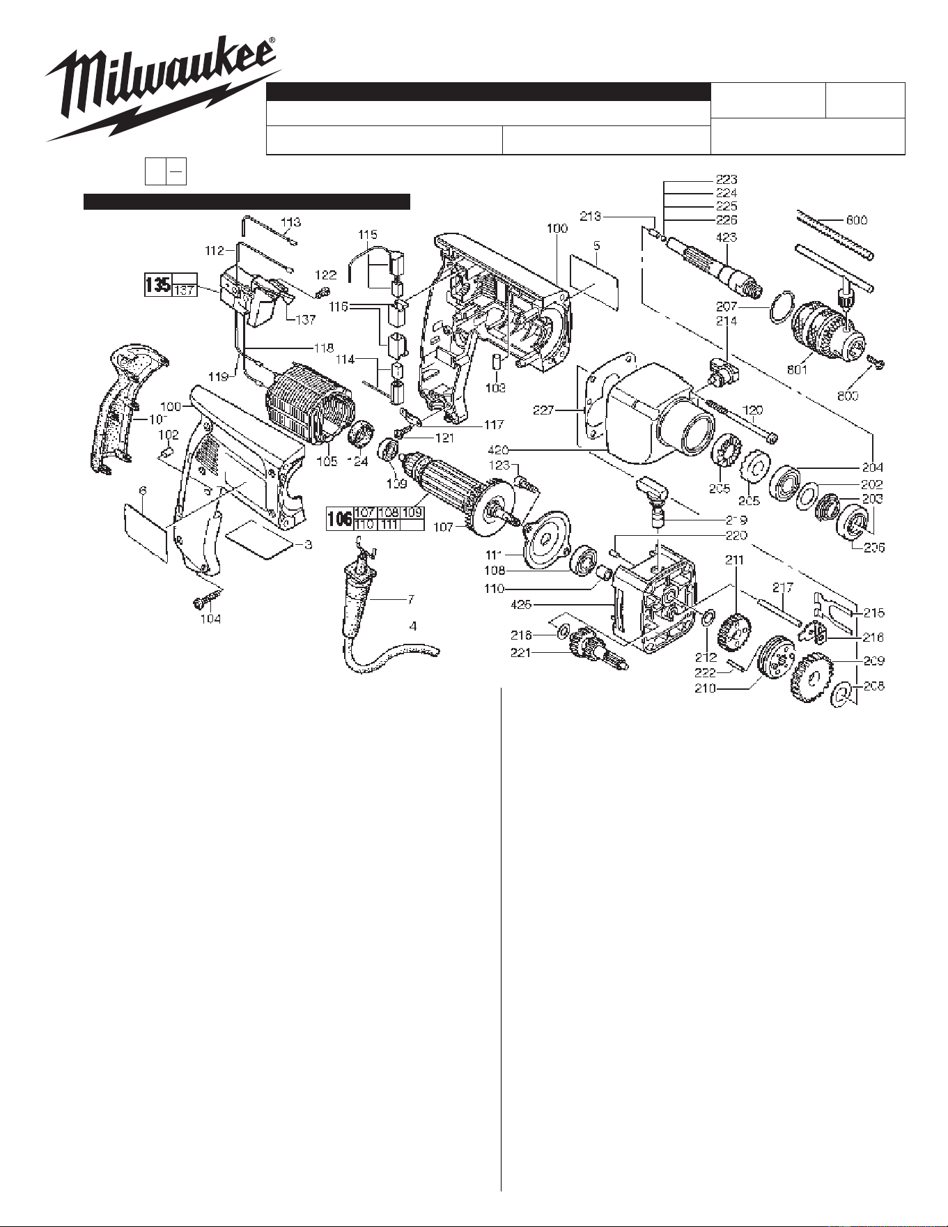
FIG. PART NO. DESCRIPTION OF PART QTY.
210 44-90-4505 Shift Ring 1
211 32-75-1227 Spindle Gear 1
212 45-88-8335 Thrust Washer 1
213 44-60-1490 Pin 1
214 44-10-0095 Shift Lever 1
215 40-50-8355 Retaining Spring 1
216 42-70-0790 Shifting Clip 1
217 44-60-1470 Pin 1
218 45-88-8345 Thrust Washer 1
219 44-10-0105 Shift Lever 1
220 44-60-1500 Pin 1
221 32-60-2637 Reduction Gear 1
222 44-60-1475 Pin 2
223 02-02-0110 Ball (4.0 Diameter) 1
224 02-02-0115 Ball (3.8 Diameter) 1
225 02-02-0125 Ball (3.6 Diameter) 1
226 02-02-0105 Ball (3.4 Diameter) 1
227 43-44-0345 Gasket 1
420 31-40-0020 Gearcase 1
423 38-50-0042 Spindle 1
425 26-28-1865 Diaphragm 1
600 43-46-0172 Depth Gauge 1
800 05-80-0430 Chuck Retaining Screw 1
801 48-66-5185 Chuck 1
49-15-5300 Side Handle 1
10-15-0270 Cord Tag 1
48-66-2110 Chuck Key 1
48-66-4040 Chuck Key Holder 1
FIG. NOTES:
223-226 The correct size ball must be chosen to properly shim out
the end play in the spindle. Spindle is to have a small
amount of end play without being tight.
SEE REVERSE SIDE FOR SERVICE & GREASE NOTES
REVISED BULLETIN
SERVICE PARTS LIST
BULLETIN NO.
EXAMPLE:
Component Parts (Small #) Are Included
When Ordering The Assembly (Large #).
WIRING INSTRUCTION
DATE
0
00
CATALOG NO.
SPECIFY CATALOG NO. AND SERIAL NO. WHEN ORDERING PARTS
SERIAL
NUMBER
MILWAUKEE ELECTRIC TOOL CORPORATION
13135 W. LISBON RD., BROOKFIELD, WI 53005
Drwg. 2
54-24-0677
FIG. PART NO. DESCRIPTION OF PART QTY.
3 12-20-0415 Nameplate 1
4 22-64-0515 Cord Set 1
5 10-07-5378 Product Label 1
6 10-07-6225 Warning Label 1
7 44-76-0290 Strain Relief 1
100 14-38-0445 Housing Assembly 1
101 44-52-0585 Handle Cushion 1
102 45-30-0055 Retaining Slug 1
103 45-30-0195 Retaining Slug 2
104 05-78-0715 Screw 6
105 18-07-0155 Service Field 1
106 16-07-0155 Service Armature 1
107 22-84-0930 Fan 1
108 02-04-1825 Ball Bearing 1
109 02-04-1820 Ball Bearing 1
110 42-40-1045 Bushing 1
111 42-92-0070 Bearing Cover 1
112 23-94-1045 Wire 1
113 23-94-1050 Wire 1
114 22-22-0885 Brush Assembly - Lower 1
115 22-22-0890 Brush Assembly - Upper 1
116 22-20-0225 Brush Holder 2
117 31-17-0240 Cord Clamp 1
118 23-94-1055 Wire 1
119 23-94-1060 Wire 1
120 06-82-9640 Screw 4
121 05-78-0720 Screw 2
122 05-81-0932 Screw 1
123 05-81-0960 Screw 2
124 45-22-0540 Rubber Sleeve 1
135 23-66-1692 Switch 1
137 --------------- Switch Lever 1
202 45-88-8295 Washer 1
203 40-50-8890 Spring 1
204 02-04-1830 Ball Bearing 1
205 44-84-0295 Ratchet 2
206 44-90-0004 Seal Ring 1
207 44-90-0365 Snap Ring (Int.) 1
208 45-88-1300 Washer 1
209 32-75-1220 Spindle Gear 1
= Part number change
from previous service
parts list.
Sept. 2006
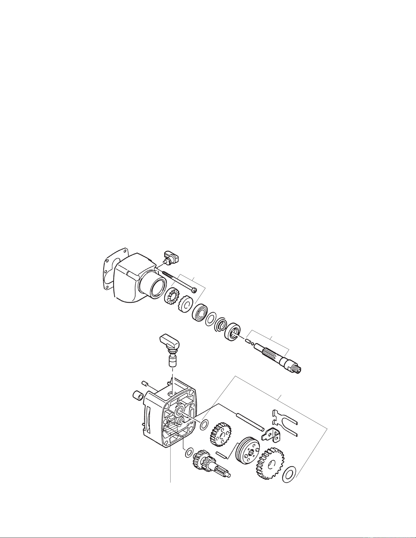
5378-20 SERVICE AND GREASE NOTES
Service Notes
1. Replace Item (102 and 103) if worn or missing.
2. Grease O-ring on Item (214) before assembly to gear case.
Greasing Instructions
Type "E" (49-08-4122)
1. Coat ratchets with 1/16 oz. of grease.
2. Coat spindle spline, pin (213) and ball (223-226) with 1/16 oz. of grease.
3. Place 1/8 oz. of grease in 1st reduction gear cavity in diaphragm.
4. Grease gear assembly (parts 208, 209, 210, 211, 212, 215, 216, 217, 218, 221 and 222)
using 1/4 oz. of grease.
Total amount of grease: 1/2 oz.
1/16 oz. Type "E"
1/16 oz. Type "E"
1/4 oz. Type "E"
1/8 oz. Type "E"