
Table of Contents
i
SAFETY PRECAUTIONS
SAFETY FIRST! ............................................................................................. 1
SCAN TOOL CONTROLS
CONTROLS AND INDICATORS .................................................................... 2
DISPLAY FUNCTIONS .................................................................................. 4
BATTERY REPLACEMENT ........................................................................... 5
ONBOARD DIAGNOSTICS
COMPUTER ENGINE CONTROLS ............................................................... 7
DIAGNOSTIC TROUBLE CODES (DTCs) .................................................... 12
OBD2 MONITORS ......................................................................................... 15
USING THE SCAN TOOL
CODE RETRIEVAL PROCEDURE ................................................................ 24
THE SYSTEM MENU ...................................................................................... 29
VIEWING OEM ENHANCED DTCs (except Ford/Mazda) ............................ 29
VIEWING OEM ENHANCED DTCs (Ford/Mazda only) ................................. 30
VIEWING ABS DTCs ...................................................................................... 32
VIEWING SRS DTCs ...................................................................................... 33
ERASING DIAGNOSTIC TROUBLE CODES (DTCs) ................................... 34
ABOUT REPAIRSOLUTIONS® ..................................................................... 36
CONNECTING TO BLUETOOTH / WIFI ....................................................... 37
CHRYSLER/JEEP OBD1 SYSTEMS
VEHICLES COVERED ................................................................................... 38
CODE RETRIEVAL PROCEDURE ................................................................ 38
ERASING DTCs ............................................................................................. 40
FORD OBD1 SYSTEMS
VEHICLES COVERED ................................................................................... 42
CODE RETRIEVAL PROCEDURES ............................................................. 45
ADDITIONAL TESTS FOR EEC-IV SYSTEMS ............................................. 52
ERASING DTCs ............................................................................................. 57
GM OBD1 SYSTEMS
VEHICLES COVERED ................................................................................... 59
CODE RETRIEVAL PROCEDURE ................................................................ 60
ERASING DTCs ............................................................................................. 62
HONDA OBD1 SYSTEMS
VEHICLES COVERED ................................................................................... 63
CODE RETRIEVAL PROCEDURE ................................................................ 63
ERASING DTCs ............................................................................................. 64
TOYOTA/LEXUS OBD1 SYSTEMS
VEHICLES COVERED ................................................................................... 66
CODE RETRIEVAL PROCEDURE ................................................................ 68
ERASING DTCs ............................................................................................. 69
LIVE DATA MODE
VIEWING LIVE DATA ..................................................................................... 71
CUSTOMIZING LIVE DATA (PIDs)................................................................. 72
RECORDING (CAPTURING) LIVE DATA ..................................................... 73
LIVE DATA PLAYBACK ................................................................................. 77
ADDITIONAL TESTS
SYSTEM TEST MENU ................................................................................... 79
RESETTING THE OIL MAINTENANCE LIGHT ............................................. 82
PERFORMING A SERVICE CHECK ............................................................. 83
BATTERY/ALTERNATOR TEST
................................................................... 84
USING THE DLC LOCATOR ......................................................................... 86
VIEWING VEHICLE INFORMATION ............................................................. 86
VIEWING THE FIRMWARE VERSION .......................................................... 88
THE TOOL LIBRARY ..................................................................................... 89
ADJUSTMENTS AND SETTINGS ................................................................. 91
USING SCAN TOOL MEMORY
VIEWING DATA IN MEMORY ....................................................................... 94
WARRANTY AND SERVICING
LIMITED ONE YEAR WARRANTY ................................................................. 97
SERVICE PROCEDURES ............................................................................. 97
Safety Precautions
SAFETY FIRST!
1
SAFETY FIRST!
This manual describes common test procedures used by experienced
service technicians. Many test procedures require precautions to avoid
accidents that can result in personal injury, and/or damage to your
vehicle or test equipment. Always read your vehicle's service manual
and follow its safety precautions before and during any test or service
procedure. ALWAYS observe the following general safety precautions:
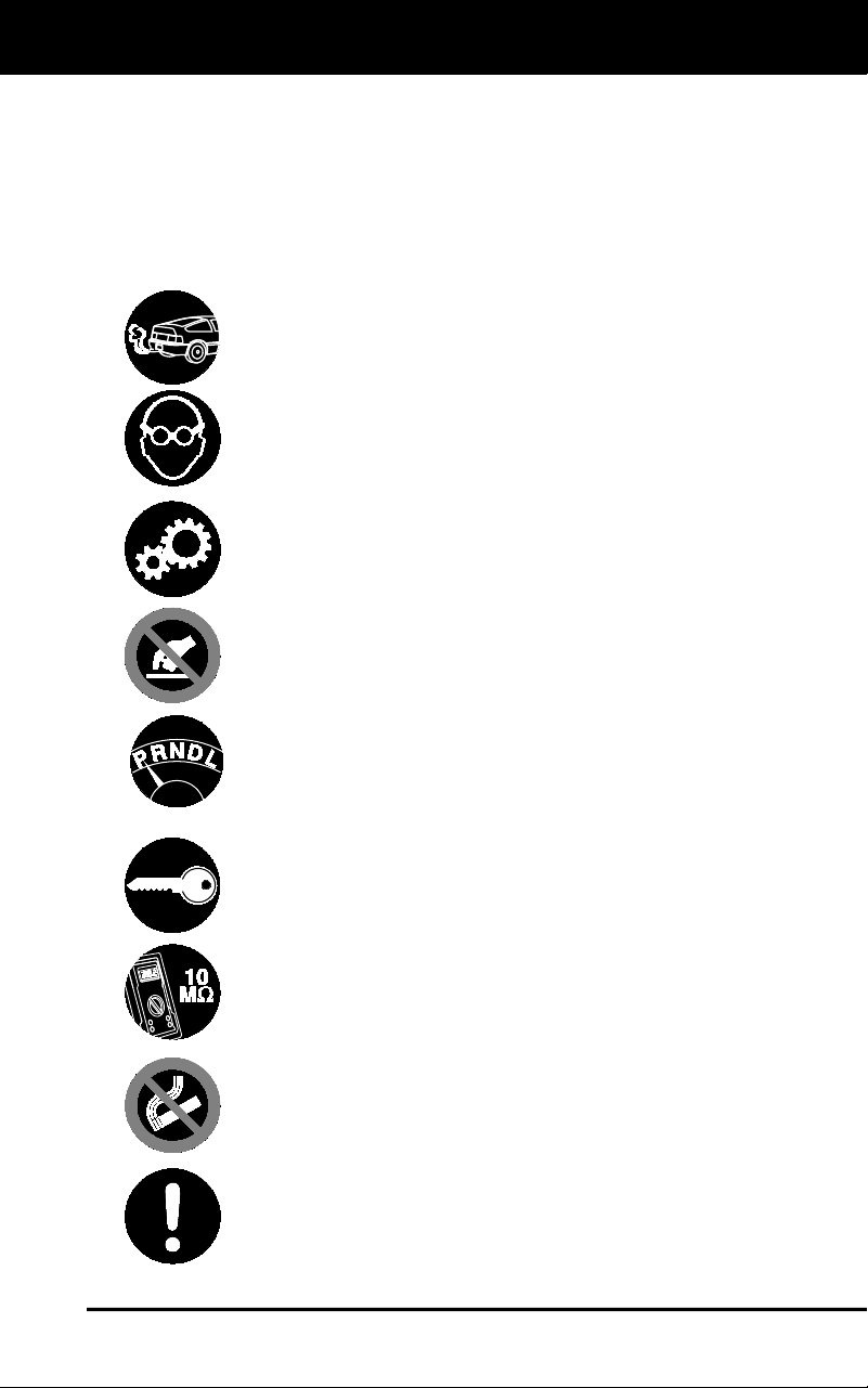
When an engine is running, it produces carbon monoxide,
a toxic and poisonous gas. To prevent serious injury or
death from carbon monoxide poisoning, operate the vehicle
ONLY in a well-ventilated area.
To protect your eyes from propelled objects as well as hot
or caustic liquids, always wear approved safety eye
protection.
When an engine is running, many parts (such as the
coolant fan, pulleys, fan belt etc.) turn at high speed. To
avoid serious injury, always be aware of moving parts.
Keep a safe distance from these parts as well as other
potentially moving objects.
Engine parts become very hot when the engine is running.
To prevent severe burns, avoid contact with hot engine parts.
Before starting an engine for testing or troubleshooting,
make sure the parking brake is engaged. Put the
transmission in park (for automatic transmission) or
neutral (for manual transmission). Block the drive wheels
with suitable blocks.
Connecting or disconnecting test equipment when the
ignition is ON can damage test equipment and the vehicle's
electronic components. Turn the ignition OFF before
connecting the Scan Tool to or disconnecting the Scan
Tool from the vehicle’s Data Link Connector (DLC).
To prevent damage to the on-board computer when taking
vehicle electrical measurements, always use a digital
multimeter with at least 10 megOhms of impedance.
Fuel and battery vapors are highly flammable. To prevent
an explosion, keep all sparks, heated items and open
flames away from the battery and fuel / fuel vapors. DO
NOT SMOKE NEAR THE VEHICLE DURING TESTING.
Don't wear loose clothing or jewelry when working on an
engine. Loose clothing can become caught in the fan,
pulleys, belts, etc. Jewelry is highly conductive, and can
cause a severe burn if it makes contact between a power
source and ground.
Scan Tool Controls
CONTROLS AND INDICATORS
2
CONTROLS AND INDICATORS
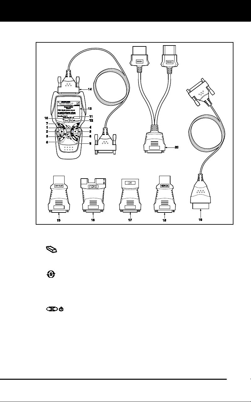
Figure 1. Controls and Indicators
See Figure 1 for the locations of items 1 through 20, below.
1.
ERASE button - Erases Diagnostic Trouble Codes (DTCs),
and “Freeze Frame” data from your vehicle’s computer, and resets
Monitor status.
2.
SYSTEM MENU button – When pressed, displays the System
Test Menu.
3. DTC/FF button - Displays the DTC View screen and/or scrolls the
LCD display to view DTCs and Freeze Frame data.
4.
POWER/LINK button - When not connected to a vehicle,
turns the Scan Tool “On” and “Off”. When connected to a vehicle,
links the Scan Tool to the vehicle’s PCM.
5. M button – When pressed, displays the Main Menu.
6. LD button – When pressed while linked to a vehicle, places the
Scan Too in Live Data mode.

Scan Tool Controls
CONTROLS AND INDICATORS
3
7. UP button – When in MENU mode, scrolls UP through the
menu options. When LINKED to a vehicle, scrolls UP through the
current display screen to display any additional data.
8.
ENTER button – When in MENU mode, confirms the selected
option or value.
9.
DOWN button - When in MENU mode, scrolls DOWN through
the menu options. When LINKED to a vehicle, scrolls DOWN
through the current display screen to display any additional data.
10. GREEN LED - Indicates that all engine systems are running
normally (all Monitors on the vehicle are active and performing their
diagnostic testing, and no DTCs are present).
11. YELLOW LED - Indicates there is a possible problem. A “Pending”
DTC is present and/or some of the vehicle’s emission monitors have
not run their diagnostic testing.
12. RED LED - Indicates there is a problem in one or more of the
vehicle’s systems. The red LED is also used to show that DTC(s)
are present. DTCs are shown on the Scan Tool’s display. In this
case, the Malfunction Indicator (“Check Engine”) lamp on the
vehicle’s instrument panel will light steady on.
13. Display - Color LCD display shows menu and submenus, test
results, Scan Tool functions and Monitor status information. See
DISPLAY FUNCTIONS (page 9) for more details.
14. CABLE - Connects the Scan Tool to the vehicle’s Data Link
Connector (DLC).
15. CHRYSLER Connector Cable Adaptor - Installs on cable (item 14)
when connecting to a Chrysler OBD1 Data Link Connector.
16. FORD Connector Cable Adaptor - Installs on cable (item 14) when
connecting to a Ford OBD1 Data Link Connector.
17. GM Connector Cable Adaptor - Installs on cable (item 14) when
connecting to a GM OBD1 Data Link Connector.
18. HONDA Connector Cable Adaptor - Installs on cable (item 14)
when connecting to a Honda OBD1 Data Link Connector.
19. OBD II Cable - Connects the scan tool to the vehicle's Data Link
Connector (DLC) when retrieving codes from OBD II systems.
20. TOYOTA Connector Cable Adaptor - Installs on cable (item 14)
when connecting to a Toyota OBD1 Data Link Connector.
Scan Tool Controls
DISPLAY FUNCTIONS
4
DISPLAY FUNCTIONS
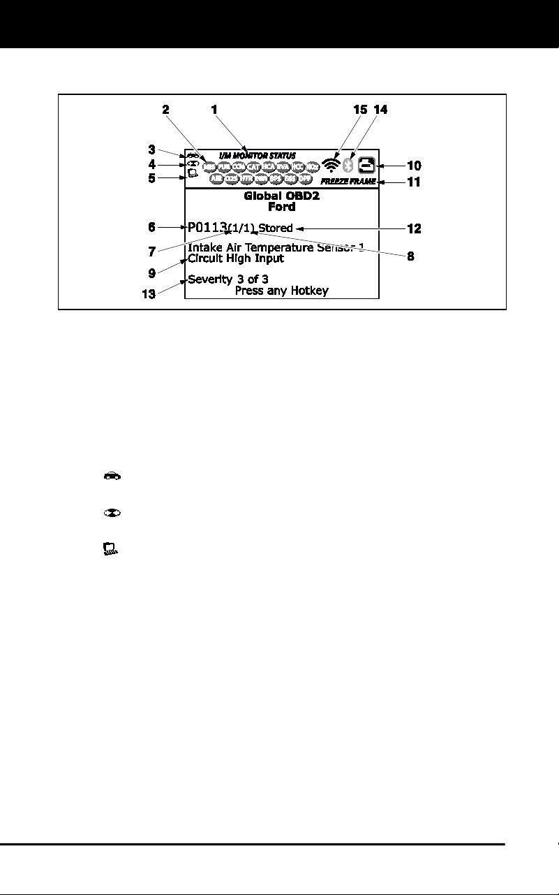
Figure 2. Display Functions
See Figure 2 for the locations of items 1 through 15, below.
1. I/M MONITOR STATUS field - Identifies the I/M Monitor status area.
2. Monitor icons - Indicate which Monitors are supported by the vehicle
under test, and whether or not the associated Monitor has run its
diagnostic testing (Monitor status). A solid green icon indicates the
associated Monitor has completed its diagnostic testing. A flashing red
icon indicates that the vehicle supports the associated Monitor, but the
Monitor has not yet run its diagnostic testing.
3.
Vehicle icon - When visible, indicates that the Scan Tool is
being powered through the vehicle’s DLC connector.
4.
Link icon - When visible, indicates the Scan Tool is
communicating with the vehicle’s computer.
5.
Computer icon - When visible, indicates the Scan Tool is linked
to a personal computer.
6. DTC Display Area - Displays the Diagnostic Trouble Code (DTC)
number. Each fault is assigned a code number that is specific to that
fault. The DTC number is color-coded as follows:
RED - Indicates the currently displayed DTC is a STORED OR
PERMANENT DTC.
YELLOW - Indicates the currently displayed DTC is a PENDING
DTC.
GREEN - In cases where no codes are retrieved, a “No DTCs
are presently stored in the vehicle’s computer” message is
shown in green.
7. Code Number Sequence - The Scan Tool assigns a sequence
number to each DTC that is present in the computer’s memory,
starting with “1.” This number indicates which code is currently
displayed. Code number “1” is always the highest priority code, and
the one for which “Freeze Frame” data has been stored.

Scan Tool Controls
BATTERY REPLACEMENT
5
If “1” is a “Pending” code, there may or may not be “Freeze
Frame” data stored in memory.
8. Code Enumerator - Indicates the total number of codes retrieved
from the vehicle’s computer.
9. Test Data Display Area - Displays DTC definitions, Freeze Frame
data and other pertinent test information messages.
10. SYSTEM icon - Indicates the system with which the code is
associated:
MIL icon ABS icon SRS icon
11. FREEZE FRAME icon - Indicates that there is Freeze Frame data
from “Priority Code” (Code #1) stored in the vehicle’s computer
memory.
12. Code type - Indicates the type of code being displayed; Generic
Stored, Generic Pending, Generic permanent, etc.
13. Severity - Indicates the level of severity for the priority code (code
number “1”), as follows:
1 - Service should be scheduled and repairs made when
convenient. This DTC typically has no immediate threat to
essential system components in the short term.
2 - Repair immediately if drivability issues are present. Threat to
essential system components if not repaired as soon as possible.
3 - Stop and repair vehicle immediately to prevent interrelated
failures. Harmful and damaging to essential system components.
14.
Bluetooth icon – Indicates communication status with a compatible
Innova mobile application (please visit www.innova.com/apps for more
information). A solid blue icon indicates an active Bluetooth connection
has been established. A solid grey icon indicates Bluetooth is not
connected.
15.
Wi-Fi icon – Indicates Wi-Fi communication status. When ON,
indicates the scan tool is linked to a Wi-Fi network. When OFF,
indicates there is no Wi-Fi connection.
BATTERY REPLACEMENT
Replace batteries when the battery symbol is visible on display
and/or the 3 LEDS are all lit and no other data is visible on screen.
1. Locate the battery cover on the back of the Scan Tool.
2. Slide the battery cover off (use your fingers).
3. Replace batteries with three AA-size batteries (for longer life, use
Alkaline-type batteries).
4. Reinstall the battery cover on the back of the Scan Tool.

Scan Tool Controls
BATTERY REPLACEMENT
6
Adjustments After Battery Installation
The first time the Scan Tool is turned on, you must select the desired
display language (English, French or Spanish) and unit of measurement
(Standard or metric) as follows:
1. Press the POWER/LINK
button to turn the Scan Tool “ON.”
The Select Language screen displays.
2. Select the desired display language, then press ENTER
.
The Select Unit screen displays.
3. Select the desired unit of measurement, then press ENTER
The Scan Tool’s Firmware Version screen displays.
After the initial language and unit of measurement selections
are performed, these, as well as other settings, can be
changed as desired. Proceed to “ADJUSTMENTS AND
SETTINGS” on page 91 for further instructions.

Onboard Diagnostics
COMPUTER ENGINE CONTROLS
7
COMPUTER ENGINE CONTROLS
The Introduction of Electronic Engine Controls
As a result of increased air pollution (smog) in large cities,
such as Los Angeles, the California Air Resources Board
(CARB) and the Environmental Protection Agency (EPA)
set new regulations and air pollution standards to deal with
the problem. To further complicate matters, the energy crisis of
the early 1970s caused a sharp increase in fuel prices over a
short period. As a result, vehicle manufacturers were not only
required to comply with the new emissions standards, they also
had to make their vehicles more fuel-efficient. Most vehicles
were required to meet a miles-per-gallon (MPG) standard set by the U.S.
Federal Government.
Precise fuel delivery and spark timing are needed to reduce vehicle
emissions. Mechanical engine controls in use at the time (such as
ignition points, mechanical spark advance and the carburetor)
responded too slowly to driving conditions to properly control fuel
delivery and spark timing. This made it difficult for vehicle manufacturers
to meet the new standards.
A new Engine Control System had to be designed and integrated with
the engine controls to meet the stricter standards. The new system had
to:
Respond instantly to supply the proper mixture of air and fuel for any
driving condition (idle, cruising, low-speed driving, high-speed
driving, etc.).
Calculate instantly the best time to “ignite” the air/fuel mixture for
maximum engine efficiency.
Perform both these tasks without affecting vehicle performance or
fuel economy.
Vehicle Computer Control Systems can perform millions of calculations
each second. This makes them an ideal substitute for the slower
mechanical engine controls. By switching from mechanical to electronic
engine controls, vehicle manufacturers are able to control fuel delivery
and spark timing more precisely. Some newer Computer Control
Systems also provide control over other vehicle functions, such as
transmission, brakes, charging, body, and suspension systems.
Electronic Computer Control Systems make it possible
for vehicle manufacturers to comply with the tougher
emissions and fuel efficiency standards mandated by
State and Federal Governments.
Onboard Diagnostics
COMPUTER ENGINE CONTROLS
8
The Basic Engine Computer Control System
The on-board computer is the heart of the Computer
Control System. The computer contains several programs
with preset reference values for air/fuel ratio, spark or
ignition timing, injector pulse width, engine speed, etc.
Separate values are provided for various driving conditions,
such as idle, low speed driving, high-speed driving, low load,
or high load. The preset reference values represent the ideal
air/fuel mixture, spark timing, transmission gear selection,
etc., for any driving condition. These values are programmed
by the vehicle manufacturer, and are specific to each vehicle model.
Most on-board computers are located inside the vehicle behind the dashboard,
under the passenger’s or driver’s seat, or behind the right kick panel. However,
some manufacturers may still position it in the engine compartment.
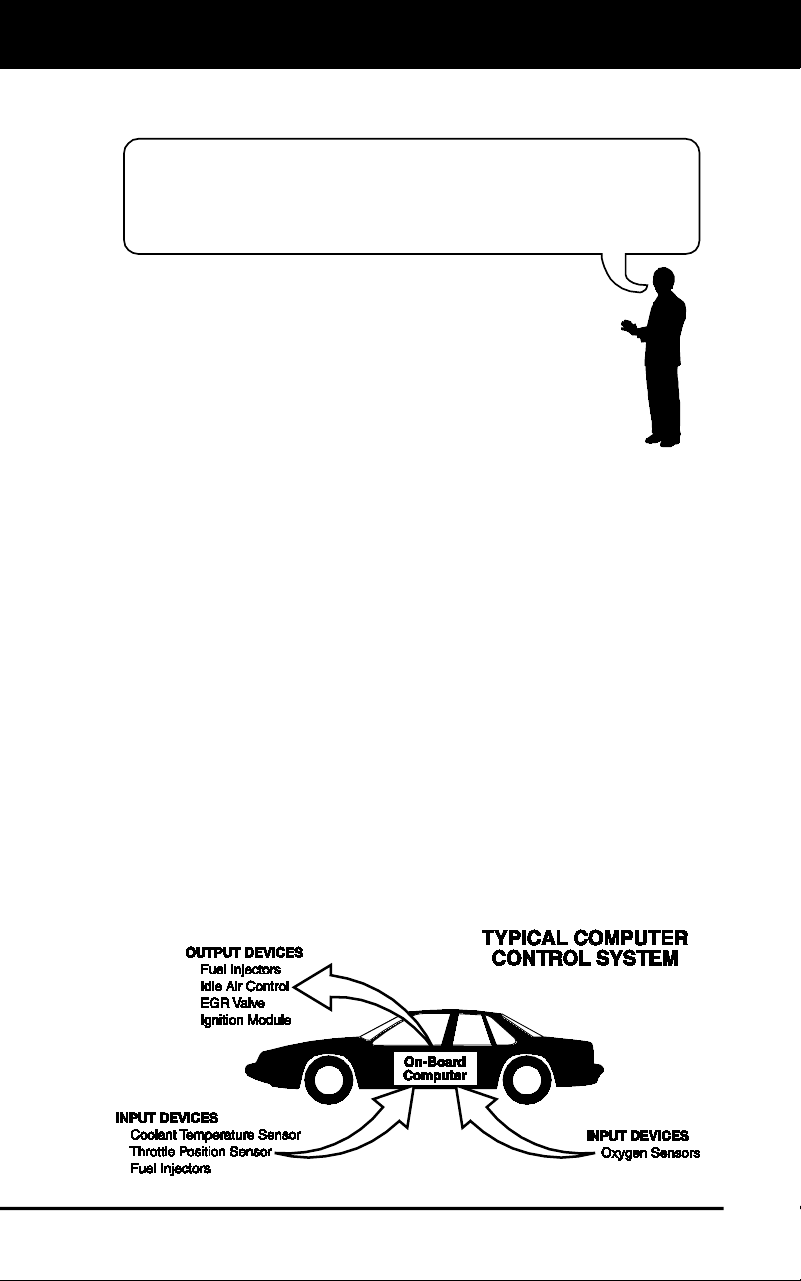
Vehicle sensors, switches, and actuators are located throughout the
engine, and are connected by electrical wiring to the on-board computer.
These devices include oxygen sensors, coolant temperature sensors,
throttle position sensors, fuel injectors, etc. Sensors and switches are
input devices. They provide signals representing current engine
operating conditions to the computer. Actuators are output devices. They
perform actions in response to commands received from the computer.
The on-board computer receives information inputs from sensors and
switches located throughout the engine. These devices monitor critical
engine conditions such as coolant temperature, engine speed, engine
load, throttle position, air/fuel ratio etc.
The computer compares the values received from these sensors with its
preset reference values, and makes corrective actions as needed so
that the sensor values always match the preset reference values for the
current driving condition. The computer makes adjustments by
commanding other devices such as the fuel injectors, idle air control,
EGR valve or Ignition Module to perform these actions.
The Computer Control System consists of an on-board
computer and several related control devices (sensors,
switches, and actuators).

Onboard Diagnostics
COMPUTER ENGINE CONTROLS
9
Vehicle operating conditions are constantly changing. The computer
continuously makes adjustments or corrections (especially to the air/fuel
mixture and spark timing) to keep all the engine systems operating
within the preset reference values.
On-Board Diagnostics - First Generation (OBD1)
Beginning in 1988, California’s Air Resources Board
(CARB), and later the Environmental Protection Agency (EPA)
required vehicle manufacturers to include a self-diagnostic
program in their on-board computers. The program would be
capable of identifying emissions-related faults in a system. The
first generation of Onboard Diagnostics came to be known as
OBD1.
OBD1 is a set of self-testing and diagnostic instructions
programmed into the vehicle’s on-board computer. The
programs are specifically designed to detect failures in the sensors,
actuators, switches and wiring of the various vehicle emissions-related
systems. If the computer detects a failure in any of these components or
systems, it lights an indicator on the dashboard to alert the driver. The
indicator lights only when an emissions-related problem is detected.
The computer also assigns a numeric code for each specific problem
that it detects, and stores these codes in its memory for later retrieval.
These codes can be retrieved from the computer’s memory with the use
of a “Code Reader” or a “Scan Tool.”
On-Board Diagnostics - Second Generation (OBD2)
In addition to performing all the
functions of the OBD1 System, the
OBD2 System has been enhanced with
new Diagnostic Programs. These
programs closely monitor the functions
of various emissions-related compo-
nents and systems (as well as other
systems) and make this information readily available (with
the proper equipment) to the technician for evaluation.
The California Air Resources Board (CARB) conducted
studies on OBD1 equipped vehicles. The information that was
gathered from these studies showed the following:
A large number of vehicles had deteriorating or degraded
emissions-related components. These components were
causing an increase in emissions.
With the exception of some 1994 and 1995 vehicles,
most vehicles from 1982 to 1995 are equipped with
some type of first generation On-Board Diagnostics.
The OBD2 System is
an enhancement of the
OBD1 System.

Onboard Diagnostics
COMPUTER ENGINE CONTROLS
10
Because OBD1 systems only detect failed components, the
degraded components were not setting codes.
Some emissions problems related to degraded components only
occur when the vehicle is being driven under a load. The emission
checks being conducted at the time were not performed under
simulated driving conditions. As a result, a significant number of
vehicles with degraded components were passing Emissions Tests.
Codes, code definitions, diagnostic connectors, communication
protocols and emissions terminology were different for each
manufacturer. This caused confusion for the technicians working on
different make and model vehicles.
To address the problems made evident by this study, CARB and the
EPA passed new laws and standardization requirements. These laws
required that vehicle manufacturers to equip their new vehicles with
devices capable of meeting all of the new emissions standards and
regulations. It was also decided that an enhanced on-board diagnostic
system, capable of addressing all of these problems, was needed. This
new system is known as “On-Board Diagnostics Generation Two
(OBD2).” The primary objective of the OBD2 system is to comply with
the latest regulations and emissions standards established by CARB
and the EPA.
The Main Objectives of the OBD2 System are:
To detect degraded and/or failed emissions-related components or
systems that could cause tailpipe emissions to exceed by 1.5 times
the Federal Test Procedure (FTP) standard.
To expand emissions-related system monitoring. This includes a set
of computer run diagnostics called Monitors. Monitors perform
diagnostics and testing to verify that all emissions-related
components and/or systems are operating correctly and within the
manufacturer’s specifications.
To use a standardized Diagnostic Link Connector (DLC) in all
vehicles. (Before OBD2, DLCs were of different shapes and sizes.)
To standardize the code numbers, code definitions and language
used to describe faults. (Before OBD2, each vehicle manufacturer
used their own code numbers, code definitions and language to
describe the same faults.)
To expand the operation of the Malfunction Indicator Lamp (MIL).
To standardize communication procedures and protocols between
the diagnostic equipment (Scan Tools, Code Readers, etc.) and the
vehicle’s on-board computer.
OBD2 Terminology
The following terms and their definitions are related to OBD2 systems.
Read and reference this list as needed to aid in the understanding of
OBD2 systems.

Onboard Diagnostics
COMPUTER ENGINE CONTROLS
11
Powertrain Control Module (PCM) - The PCM is the OBD2
accepted term for the vehicle’s “on-board computer.” In addition
to controlling the engine management and emissions systems,
the PCM also participates in controlling the powertrain
(transmission) operation. Most PCMs also have the ability to
communicate with other computers on the vehicle (ABS, ride
control, body, etc.).
Monitor - Monitors are “diagnostic routines” programmed into the
PCM. The PCM utilizes these programs to run diagnostic tests, and
to monitor operation of the vehicle’s emissions-related components
or systems to ensure they are operating correctly and within the
vehicle’s manufacturer specifications. Currently, up to fifteen
Monitors are used in OBD2 systems. Additional Monitors will be
added as the OBD2 system is further developed.
Not all vehicles support all fifteen Monitors.
Enabling Criteria - Each Monitor is designed to test and monitor
the operation of a specific part of the vehicle’s emissions system
(EGR system, oxygen sensor, catalytic converter, etc.). A specific
set of “conditions” or “driving procedures” must be met before the
computer can command a Monitor to run tests on its related system.
These “conditions” are known as “Enabling Criteria.” The
requirements and procedures vary for each Monitor. Some Monitors
only require the ignition key to be turned “On” for them to run and
complete their diagnostic testing. Others may require a set of
complex procedures, such as, starting the vehicle when cold,
bringing it to operating temperature, and driving the vehicle under
specific conditions before the Monitor can run and complete its
diagnostic testing.
Monitor Has/Has Not Run - The terms “Monitor has run” or
“Monitor has not run” are used throughout this manual. “Monitor
has run,” means the PCM has commanded a particular Monitor to
perform the required diagnostic testing on a system to ensure the
system is operating correctly (within factory specifications). The term
“Monitor has not run” means the PCM has not yet commanded a
particular Monitor to perform diagnostic testing on its associated part
of the emissions system.
Trip - A Trip for a particular Monitor requires that the vehicle is
being driven in such a way that all the required “Enabling Criteria”
for the Monitor to run and complete its diagnostic testing are met.
The “Trip Drive Cycle” for a particular Monitor begins when the
ignition key is turned “On.” It is successfully completed when all the
“Enabling Criteria” for the Monitor to run and complete its diagnostic
testing are met by the time the ignition key is turned “Off.” Since
each of the fifteen monitors is designed to run diagnostics and
testing on a different part of the engine or emissions system, the
“Trip Drive Cycle” needed for each individual Monitor to run and
complete varies.

Onboard Diagnostics
DIAGNOSTIC TROUBLE CODES (DTCs)
12
OBD2 Drive Cycle - An OBD2 Drive Cycle is an extended set of
driving procedures that takes into consideration the various types of
driving conditions encountered in real life. These conditions may
include starting the vehicle when it is cold, driving the vehicle at a
steady speed (cruising), accelerating, etc. An OBD2 Drive Cycle
begins when the ignition key is turned “On” (when cold) and ends
when the vehicle has been driven in such a way as to have all the
“Enabling Criteria” met for all its applicable Monitors. Only those
trips that provide the Enabling Criteria for all Monitors applicable to
the vehicle to run and complete their individual diagnostic tests
qualify as an OBD2 Drive Cycle. OBD2 Drive Cycle requirements
vary from one model of vehicle to another. Vehicle manufacturers
set these procedures. Consult your vehicle’s service manual for
OBD2 Drive Cycle procedures.
Do not confuse a “Trip” Drive Cycle with an OBD2 Drive Cycle. A
“Trip” Drive Cycle provides the “Enabling Criteria” for one specific
Monitor to run and complete its diagnostic testing. An OBD2 Drive
Cycle must meet the “Enabling Criteria” for all Monitors on a
particular vehicle to run and complete their diagnostic testing.
Warm-up Cycle - Vehicle operation after an engine off period where
engine temperature rises at least 40°F (22°C) from its temperature
before starting, and reaches at least 160°F (70°C). The PCM uses
warm-up cycles as a counter to automatically erase a specific code
and related data from its memory. When no faults related to the
original problem are detected within a specified number of warm-up
cycles, the code is erased automatically.
DIAGNOSTIC TROUBLE CODES (DTCs)
Diagnostic Trouble Codes (DTCs) are
meant to guide you to the proper
service procedure in the vehicle’s
service manual. DO NOT replace parts
based only on DTCs without first
consulting the vehicle’s service manual
for proper testing procedures for that
particular system, circuit or component.
DTCs are alphanumeric codes that are used to identify a
problem that is present in any of the systems that are
monitored by the on-board computer (PCM). Each trouble
code has an assigned message that identifies the circuit,
component or system area where the problem was found.
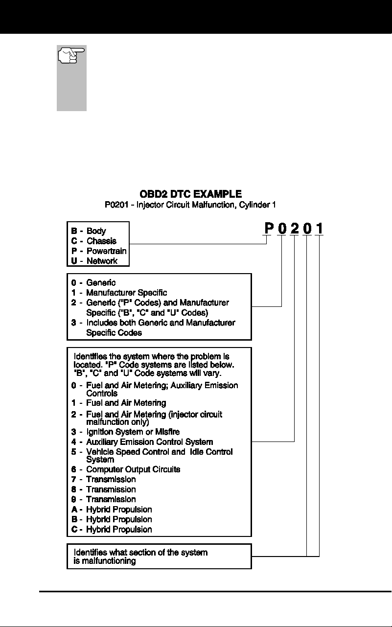
OBD2 diagnostic trouble codes are made up of five characters:
The 1st character is a letter (B, C, P or U). It identifies the
“main system” where the fault occurred (Body, Chassis, Powertrain,
or Network).
The 2nd character is a numeric digit (0 thru 3). It identifies the
“type” of code (Generic or Manufacturer-Specific).
Generic DTCs are codes that are used by all vehicle manu-
facturers. The standards for generic DTCs, as well as their
definitions, are set by the Society of Automotive Engineers (SAE).
Diagnostic Trouble
Codes (DTCs) are
codes that identify a
specific problem area.
Onboard Diagnostics
DIAGNOSTIC TROUBLE CODES (DTCs)
13
Manufacturer-Specific DTCs are codes that are controlled by
the vehicle manufacturers. The Federal Government does not
require vehicle manufacturers to go beyond the standardized
generic DTCs in order to comply with the new OBD2 emissions
standards. However, manufacturers are free to expand beyond
the standardized codes to make their systems easier to
diagnose.
The 3rd character is a letter or a numeric digit (0 thru 9, A thru F).
It identifies the specific system or sub-system where the problem is
located.
The 4th and 5th characters are letters or numeric digits (0 thru 9, A
thru F). They identify the section of the system that is malfunctioning.

Onboard Diagnostics
DIAGNOSTIC TROUBLE CODES (DTCs)
14
DTCs and MIL Status
When the vehicle’s on-board computer detects
a failure in an emissions-related component or
system, the computer’s internal diagnostic
program assigns a diagnostic trouble code
(DTC) that points to the system (and subsystem)
where the fault was found. The diagnostic
program saves the code in the computer’s
memory. It records a “Freeze Frame” of
conditions present when the fault was found, and lights the Malfunction
Indicator Lamp (MIL). Some faults require detection for two trips in a row
before the MIL is turned on.
The “Malfunction Indicator Lamp” (MIL) is the accepted term
used to describe the lamp on the dashboard that lights to warn
the driver that an emissions-related fault has been found.
Some manufacturers may still call this lamp a “Check Engine”
or “Service Engine Soon” light.
There are two types of DTCs used for emissions-related faults: Type “A”
and Type “B.” Type “A” codes are “One-Trip” codes; Type “B” DTCs are
usually Two-Trip DTCs.
When a Type “A” DTC is found on the First Trip, the following events
take place:
The computer commands the MIL “On” when the failure is first found.
If the failure causes a severe misfire that may cause damage to the
catalytic converter, the MIL “flashes” once per second. The MIL
continues to flash as long as the condition exists. If the condition
that caused the MIL to flash is no longer present, the MIL will light
“steady” On.
A DTC is saved in the computer’s memory for later retrieval.
A “Freeze Frame” of the conditions present in the engine or emissions
system when the MIL was ordered “On” is saved in the computer’s
memory for later retrieval. This information shows fuel system status
(closed loop or open loop), engine load, coolant temperature, fuel trim
value, MAP vacuum, engine RPM and DTC priority.
When a Type “B” DTC is found on the First Trip, the following events
take place:
The computer sets a Pending DTC, but the MIL is not ordered “On.”
“Freeze Frame” data may or may not be saved at this time
depending on manufacturer. The Pending DTC is saved in the
computer’s memory for later retrieval.
If the failure is found on the second consecutive trip, the MIL is
ordered “On.” “Freeze Frame” data is saved in the computer’s
memory.
If the failure is not found on the second Trip, the Pending DTC is
erased from the computer’s memory.
The MIL will stay lit for both Type “A” and Type “B” codes until one of
the following conditions occurs:

Onboard Diagnostics
OBD2 MONITORS
15
If the conditions that caused the MIL to light are no longer present
for the next three trips in a row, the computer automatically turns the
MIL “Off” if no other emissions-related faults are present. However,
the DTCs remain in the computer’s memory as a history code for 40
warm-up cycles (80 warm-up cycles for fuel and misfire faults). The
DTCs are automatically erased if the fault that caused them to be
set is not detected again during that period.
Misfire and fuel system faults require three trips with “similar
conditions” before the MIL is turned “Off.” These are trips where the
engine load, RPM and temperature are similar to the conditions
present when the fault was first found.
After the MIL has been turned off, DTCs and Freeze Frame
data stay in the computer’s memory.
Erasing the DTCs from the computer’s memory can also turn off the
MIL. See ERASING DIAGNOSTIC TROUBLE CODES (DTCs) on
page 34, before erasing codes from the computer’s memory. If a
Diagnostic Tool or Scan Tool is used to erase the codes, Freeze
Frame data will also be erased.
OBD2 MONITORS
To ensure the correct operation of the various emissions-related
components and systems, a diagnostic program was developed and
installed in the vehicle’s on-board computer. The program has several
procedures and diagnostic strategies. Each procedure or diagnostic
strategy is made to monitor the operation of, and run diagnostic tests on,
a specific emissions-related component or system. These tests ensure
the system is running correctly and is within the manufacturer’s
specifications. On OBD2 systems, these procedures and diagnostic
strategies are called “Monitors.”
Currently, fifteen Monitors are supported by OBD2 systems. Additional
monitors may be added as a result of Government regulations as the
OBD2 system grows and matures. Not all vehicles support all fifteen
Monitors. Additionally, some Monitors are supported by “spark ignition”
vehicles only, while others are supported by “compression ignition”
vehicles only.
Monitor operation is either “Continuous” or “Non-Continuous,”
depending on the specific monitor.
Continuous Monitors
Three of these Monitors are designed to constantly monitor their
associated components and/or systems for proper operation.
Continuous Monitors run constantly when the engine is running. The
Continuous Monitors are:
Comprehensive Component Monitor (CCM)
Misfire Monitor
Fuel System Monitor
Onboard Diagnostics
OBD2 MONITORS
16
Non-Continuous Monitors
The other twelve Monitors are “non-continuous” Monitors. “Non-
continuous” Monitors perform and complete their testing once per trip.
The “non-continuous” Monitors are:
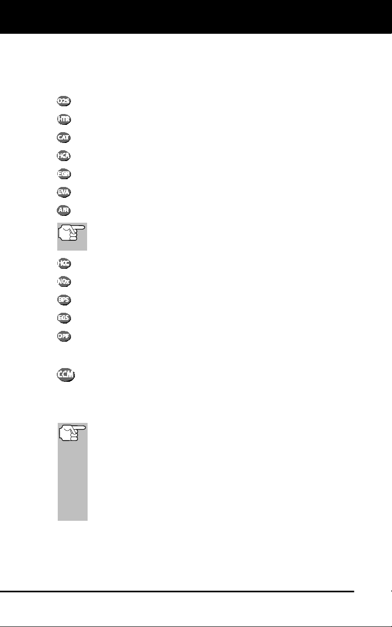
Oxygen Sensor Monitor
Oxygen Sensor Heater Monitor
Catalyst Monitor
Heated Catalyst Monitor
EGR System Monitor
EVAP System Monitor
Secondary Air System Monitor
The following Monitors became standard beginning in 2010.
The majority of vehicles produced before this time will not
support these Monitors
NMHC Monitor
NOx Adsorber Monitor
Boost Pressure System Monitor
Exhaust Gas Sensor Monitor
PM Filter Monitor
The following provides a brief explanation of the function of each Monitor:
Comprehensive Component Monitor (CCM) - This Monitor
continuously checks all inputs and outputs from sensors,
actuators, switches and other devices that provide a signal to the
computer. The Monitor checks for shorts, opens, out of range value,
functionality and “rationality.”
Rationality: Each input signal is compared against all other
inputs and against information in the computer’s memory to see
if it makes sense under the current operating conditions.
Example: The signal from the throttle position sensor indicates
the vehicle is in a wide-open throttle condition, but the vehicle is
really at idle, and the idle condition is confirmed by the signals
from all other sensors. Based on the input data, the computer
determines that the signal from the throttle position sensor is not
rational (does not make sense when compared to the other
inputs). In this case, the signal would fail the rationality test.
The CCM is supported by both “spark ignition” vehicles and
“compression ignition” vehicles. The CCM may be either a “One-Trip” or
a “Two-Trip” Monitor, depending on the component.

Onboard Diagnostics
OBD2 MONITORS
17
Fuel System Monitor - This Monitor uses a Fuel System
Correction program, called Fuel Trim, inside the on-board
computer. Fuel Trim is a set of positive and negative values that
represent adding or subtracting fuel from the engine. This program is
used to correct for a lean (too much air/not enough fuel) or rich (too
much fuel/not enough air) air-fuel mixture. The program is designed to
add or subtract fuel, as needed, up to a certain percent. If the correction
needed is too large and exceeds the time and percent allowed by the
program, a fault is indicated by the computer.
The Fuel System Monitor is supported by both “spark ignition” vehicles
and “compression ignition” vehicles. The Fuel System Monitor may be a
“One-Trip” or “Two-Trip” Monitor, depending on the severity of the
problem.
Misfire Monitor - This Monitor continuously checks for engine misfires.
A misfire occurs when the air-fuel mixture in the cylinder does not
ignite. The misfire Monitor uses changes in crankshaft speed to sense an
engine misfire. When a cylinder misfires, it no longer contributes to the speed
of the engine, and engine speed decreases each time the affected cylinder(s)
misfire. The misfire Monitor is designed to sense engine speed fluctuations
and determine from which cylinder(s) the misfire is coming, as well as how
bad the misfire is. There are three types of engine misfires, Types 1, 2, and 3.
- Type 1 and Type 3 misfires are two-trip monitor faults. If a fault is sensed
on the first trip, the computer temporarily saves the fault in its memory as
a Pending Code. The MIL is not commanded on at this time. If the fault is
found again on the second trip, under similar conditions of engine speed,
load and temperature, the computer commands the MIL “On,” and the
code is saved in its long term memory.
- Type 2 misfires are the most severe type of misfire. When a Type 2
misfire is sensed on the first trip, the computer commands the MIL to
light when the misfire is sensed. If the computer determines that a
Type 2 misfire is severe , and may cause catalytic converter damage,
it commands the MIL to “flash” once per second as soon as the
misfire is sensed. When the misfire is no longer present, the MIL
reverts to steady “On” condition.
The Misfire Monitor is supported by both “spark ignition” vehicles and
“compression ignition” vehicles.
Catalyst Monitor - The catalytic converter is a device that is
installed downstream of the exhaust manifold. It helps to oxidize
(burn) the unburned fuel (hydrocarbons) and partially burned fuel
(carbon monoxide) left over from the combustion process. To
accomplish this, heat and catalyst materials inside the converter react
with the exhaust gases to burn the remaining fuel. Some materials
inside the catalytic converter also have the ability to store oxygen, and
release it as needed to oxidize hydrocarbons and carbon monoxide. In
the process, it reduces vehicle emissions by converting the polluting
gases into carbon dioxide and water.
The computer checks the efficiency of the catalytic converter by
monitoring the oxygen sensors used by the system. One sensor is located
before (upstream of) the converter; the other is located after (downstream
of) the converter. If the catalytic converter loses its ability to store oxygen,

Onboard Diagnostics
OBD2 MONITORS
18
the downstream sensor signal voltage becomes almost the same as the
upstream sensor signal. In this case, the monitor fails the test.
The Catalyst Monitor is supported by “spark ignition” vehicles only. The
Catalyst Monitor is a “Two-Trip” Monitor. If a fault is found on the first
trip, the computer temporarily saves the fault in its memory as a
Pending Code. The computer does not command the MIL on at this time.
If the fault is sensed again on the second trip, the computer commands
the MIL “On” and saves the code in its long-term memory.
Heated Catalyst Monitor - Operation of the “heated” catalytic
converter is similar to the catalytic converter. The main
difference is that a heater is added to bring the catalytic converter to its
operating temperature more quickly. This helps reduce emissions by
reducing the converter’s down time when the engine is cold. The Heated
Catalyst Monitor performs the same diagnostic tests as the catalyst
Monitor, and also tests the catalytic converter’s heater for proper
operation.
The Heated Catalyst Monitor is supported by “spark ignition” vehicles
only. This Monitor is also a “Two-Trip” Monitor.
Exhaust Gas Recirculation (EGR) Monitor - The Exhaust Gas
Recirculation (EGR) system helps reduce the formation of
Oxides of Nitrogen during combustion. Temperatures above 2500°F
cause nitrogen and oxygen to combine and form Oxides of Nitrogen in
the combustion chamber. To reduce the formation of Oxides of Nitrogen,
combustion temperatures must be kept below 2500°F. The EGR system
recirculates small amounts of exhaust gas back into the intake manifold,
where it is mixed with the incoming air/fuel mixture. This reduces
combustion temperatures by up to 500°F. The computer determines
when, for how long, and how much exhaust gas is recirculated back to
the intake manifold. The EGR Monitor performs EGR system function
tests at preset times during vehicle operation.
The EGR Monitor is supported by both “spark ignition” vehicles and
“compression ignition” vehicles. The EGR Monitor is a “Two-Trip”
Monitor. If a fault is found on the first trip, the computer temporarily
saves the fault in its memory as a Pending Code. The computer does
not command the MIL on at this time. If the fault is sensed again on the
second trip, the computer commands the MIL “On,” and saves the code
in its long-term memory.
Evaporative System (EVAP) Monitor - OBD2 vehicles are
equipped with a fuel Evaporative system (EVAP) that helps
prevent fuel vapors from evaporating into the air. The EVAP system
carries fumes from the fuel tank to the engine where they are burned
during combustion. The EVAP system may consist of a charcoal
canister, fuel tank cap, purge solenoid, vent solenoid, flow monitor, leak
detector and connecting tubes, lines and hoses.
Fumes are carried from the fuel tank to the charcoal canister by hoses
or tubes. The fumes are stored in the charcoal canister. The computer
controls the flow of fuel vapors from the charcoal canister to the engine
via a purge solenoid. The computer energizes or de-energizes the purge
solenoid (depending on solenoid design). The purge solenoid opens a

Onboard Diagnostics
OBD2 MONITORS
19
valve to allow engine vacuum to draw the fuel vapors from the canister
into the engine where the vapors are burned. The EVAP Monitor checks
for proper fuel vapor flow to the engine, and pressurizes the system to
test for leaks. The computer runs this Monitor once per trip.
The EVAP Monitor is supported by “spark ignition” vehicles only. The
EVAP Monitor is a “Two-Trip” Monitor. If a fault is found on the first trip,
the computer temporarily saves the fault in its memory as a Pending
Code. The computer does not command the MIL on at this time. If the
fault is sensed again on the second trip, the PCM commands the MIL
“On,” and saves the code in its long-term memory.
Oxygen Sensor Heater Monitor - The Oxygen Sensor Heater
Monitor tests the operation of the oxygen sensor’s heater. There
are two modes of operation on a computer-controlled vehicle: “open-
loop” and “closed-loop.” The vehicle operates in open-loop when the
engine is cold, before it reaches normal operating temperature. The
vehicle also goes to open-loop mode at other times, such as heavy load
and full throttle conditions. When the vehicle is running in open-loop, the
oxygen sensor signal is ignored by the computer for air/fuel mixture
corrections. Engine efficiency during open-loop operation is very low,
and results in the production of more vehicle emissions.
Closed-loop operation is the best condition for both vehicle emissions
and vehicle operation. When the vehicle is operating in closed-loop, the
computer uses the oxygen sensor signal for air/fuel mixture corrections.
In order for the computer to enter closed-loop operation, the oxygen
sensor must reach a temperature of at least 600°F. The oxygen sensor
heater helps the oxygen sensor reach and maintain its minimum
operating temperature (600°F) more quickly, to bring the vehicle into
closed-loop operation as soon as possible.
The Oxygen Sensor Heater Monitor is supported by “spark ignition”
vehicles only. The Oxygen Sensor Heater Monitor is a “Two-Trip”
Monitor. If a fault is found on the first trip, the computer temporarily
saves the fault in its memory as a Pending Code. The computer does
not command the MIL on at this time. If the fault is sensed again on the
second trip, the computer commands the MIL “On,” and saves the code
in its long-term memory.
Oxygen Sensor Monitor - The Oxygen Sensor monitors how
much oxygen is in the vehicle’s exhaust. It generates a varying
voltage of up to one volt, based on how much oxygen is in the exhaust
gas, and sends the signal to the computer. The computer uses this
signal to make corrections to the air/fuel mixture. If the exhaust gas has
a large amount of oxygen (a lean air/fuel mixture), the oxygen sensor
generates a “low” voltage signal. If the exhaust gas has very little
oxygen (a rich mixture condition), the oxygen sensor generates a “high”
voltage signal. A 450mV signal indicates the most efficient, and least
polluting, air/fuel ratio of 14.7 parts of air to one part of fuel.
The oxygen sensor must reach a temperature of at least 600-650°F,
and the engine must reach normal operating temperature, for the
computer to enter into closed-loop operation. The oxygen sensor only
functions when the computer is in closed-loop. A properly operating

Onboard Diagnostics
OBD2 MONITORS
20
oxygen sensor reacts quickly to any change in oxygen content in the
exhaust stream. A faulty oxygen sensor reacts slowly, or its voltage
signal is weak or missing.
The Oxygen Sensor Monitor is supported by “spark ignition” vehicles
only. The Oxygen Sensor Monitor is a “Two-Trip” monitor. If a fault is
found on the first trip, the computer temporarily saves the fault in its
memory as a Pending Code. The computer does not command the MIL
on at this time. If the fault is sensed again on the second trip, the
computer commands the MIL “On,” and saves the code in its long-term
memory.
Secondary Air System Monitor - When a cold engine is first
started, it runs in open-loop mode. During open-loop operation,
the engine usually runs rich. A vehicle running rich wastes fuel and
creates increased emissions, such as carbon monoxide and some
hydrocarbons. A Secondary Air System injects air into the exhaust
stream to aid catalytic converter operation:
4. It supplies the catalytic converter with the oxygen it needs to oxidize
the carbon monoxide and hydrocarbons left over from the
combustion process during engine warm-up.
5. The extra oxygen injected into the exhaust stream also helps the
catalytic converter reach operating temperature more quickly during
warm-up periods. The catalytic converter must heat to operating
temperature to work properly.
The Secondary Air System Monitor checks for component integrity and
system operation, and tests for faults in the system. The computer runs
this Monitor once per trip.
The Secondary Air System Monitor is a “Two-Trip” monitor. If a fault is
found on the first trip, the computer temporarily saves this fault in its
memory as a Pending Code. The computer does not command the MIL
on at this time. If the fault is sensed again on the second trip, the
computer commands the MIL “On,” and saves the code in its long-term
memory.
Non-Methane Hydrocarbon Catalyst (NMHC) Monitor - The
non-methane hydrocarbon catalyst is a type of catalytic
converter. It helps to remove non-methane hydrocarbons (NMH) left
over from the combustion process from the exhaust stream. To
accomplish this, heat and catalyst materials react with the exhaust
gases to convert NMH to less harmful compounds. The computer checks
the efficiency of the catalyst by monitoring the quantity of NMH in the
exhaust stream. The monitor also verifies that sufficient temperature is
present to aid in particulate matter (PM) filter regeneration.
The NMHC Monitor is supported by “compression ignition” vehicles only.
The NMHC Monitor is a “Two-Trip” Monitor. If a fault is found on the first
trip, the computer temporarily saves the fault in its memory as a
Pending Code. The computer does not command the MIL on at this time.
If the fault is sensed again on the second trip, the computer commands
the MIL “On,” and saves the code in its long-term memory.

Onboard Diagnostics
OBD2 MONITORS
21
NOx Aftertreatment Monitor - NOx aftertreatment is based on a
catalytic converter support that has been coated with a special
washcoat containing zeolites. NOx Aftertreatment is designed to reduce
oxides of nitrogen emitted in the exhaust stream. The zeolite acts as a
molecular "sponge" to trap the NO and NO2 molecules in the exhaust
stream. In some implementations, injection of a reactant before the
aftertreatment purges it. NO2 in particular is unstable, and will join with
hydrocarbons to produce H2O and N2. The NOx Aftertreatment Monitor
monitors the function of the NOx aftertreatment to ensure that tailpipe
emissions remain within acceptable limits.
The NOx Aftertreatment Monitor is supported by “compression ignition”
vehicles only. The NOx Aftertreatment Monitor is a “Two-Trip” Monitor. If
a fault is found on the first trip, the computer temporarily saves the fault
in its memory as a Pending Code. The computer does not command the
MIL on at this time. If the fault is sensed again on the second trip, the
computer commands the MIL “On,” and saves the code in its long-term
memory.
Boost Pressure System Monitor - The boost pressure system
serves to increase the pressure produced inside the intake
manifold to a level greater than atmospheric pressure. This increase in
pressure helps to ensure compete combustion of the air-fuel mixture.
The Boost Pressure System Monitor checks for component integrity and
system operation, and tests for faults in the system. The computer runs
this Monitor once per trip.
The Boost Pressure System Monitor is supported by “compression
ignition” vehicles only. The Boost Pressure System Monitor is a “Two-
Trip” Monitor. If a fault is found on the first trip, the computer temporarily
saves the fault in its memory as a Pending Code. The computer does
not command the MIL on at this time. If the fault is sensed again on the
second trip, the computer commands the MIL “On,” and saves the code
in its long-term memory.
Exhaust Gas Sensor Monitor - The exhaust gas sensor is used
by a number of systems/monitors to determine the content of the
exhaust stream. The computer checks for component integrity, system
operation, and tests for faults in the system, as well as feedback faults
that may affect other emission control systems.
The Exhaust Gas Sensor Monitor is supported by “compression ignition”
vehicles only. The Exhaust Gas Sensor Monitor is a “Two-Trip” Monitor.
If a fault is found on the first trip, the computer temporarily saves the
fault in its memory as a Pending Code. The computer does not
command the MIL on at this time. If the fault is sensed again on the
second trip, the computer commands the MIL “On,” and saves the code
in its long-term memory.

Onboard Diagnostics
OBD2 MONITORS
22
PM Filter Monitor - The particulate matter (PM) filter removes
particulate matter from the exhaust stream by filtration. The filter
has a honeycomb structure similar to a catalyst substrate, but with the
channels blocked at alternate ends. This forces the exhaust gas to flow
through the walls between the channels, filtering the particulate matter
out. The filters are self-cleaning by periodic modification of the exhaust
gas concentration in order to burn off the trapped particles (oxidizing the
particles to form CO2 and water). The computer monitors the efficiency
of the filter in trapping particulate matter, as well as the ability of the filter
to regenerate (self-clean).
The PM Filter Monitor is supported by “compression ignition” vehicles
only. The PM Filter Monitor is a “Two-Trip” Monitor. If a fault is found on
the first trip, the computer temporarily saves the fault in its memory as a
Pending Code. The computer does not command the MIL on at this time.
If the fault is sensed again on the second trip, the computer commands
the MIL “On,” and saves the code in its long-term memory.
OBD2 Reference Table
The table below lists current OBD2 Monitors, and indicates the following
for each Monitor:
A. Monitor Type (how often does the Monitor run; Continuous or
Once per trip)
B. Number of trips needed, with a fault present, to set a pending DTC
C. Number of consecutive trips needed, with a fault present, to
command the MIL “On” and store a DTC
D. Number of trips needed, with no faults present, to erase a Pending
DTC
E. Number and type of trips or drive cycles needed, with no faults
present, to turn off the MIL
F. Number of warm-up periods needed to erase the DTC from the
computer’s memory after the MIL is turned off

Onboard Diagnostics
OBD2 MONITORS
23
Name of
Monitor
A
B
C
D
E
F
Comprehensive
Component Monitor
Continuous 1 2 1 3 40
Misfire Monitor
(Type 1 and 3)
Continuous 1 2 1
3 - similar
conditions
80
Misfire Monitor
(Type 2)
Continuous 1
3 - similar
conditions
80
Fuel System Monitor
Continuous 1 1 or 2 1
3 - similar
conditions
80
Catalytic Converter
Monitor
Once per
trip
1 2 1 3 trips 40
Oxygen Sensor
Monitor
Once per
trip
1 2 1 3 trips 40
Oxygen Sensor
Heater Monitor
Once per
trip
1 2 1 3 trips 40
Exhaust Gas
Recirculation (EGR)
Monitor
Once per
trip
1 2 1 3 trips 40
Evaporative
Emissions Controls
Monitor
Once per
trip
1 2 1 3 trips 40
Secondary Air
System (AIR) Monitor
Once per
trip
1 2 1 3 trips 40
NMHC Monitor
Once per
trip
1 2 1 3 trips 40
Nox Adsorber Monitor
Once per
trip
1 2 1 3 trips 40
Boost Pressure
System Monitor
Once per
trip
1 2 1 3 trips 40
Exhaust Gas Sensor
Monitor
Once per
trip
1 2 1 3 trips 40
PM Filter Monitor
Once per
trip
1 2 1 3 trips 40
Using the Scan Tool
CODE RETRIEVAL PROCEDURE
24
Retrieving and using Diagnostic Trouble Codes (DTCs) for
troubleshooting vehicle operation is only one part of an
overall diagnostic strategy.
CODE RETRIEVAL PROCEDURE
Never replace a part based only on the DTC definition.
Each DTC has a set of testing procedures, instructions and
flow charts that must be followed to confirm the location of
the problem. Always refer to the vehicle's service manual
for detailed testing instructions.
Check your vehicle thoroughly before performing
any test.
ALWAYS observe safety precau-
tions whenever working on a
vehicle.
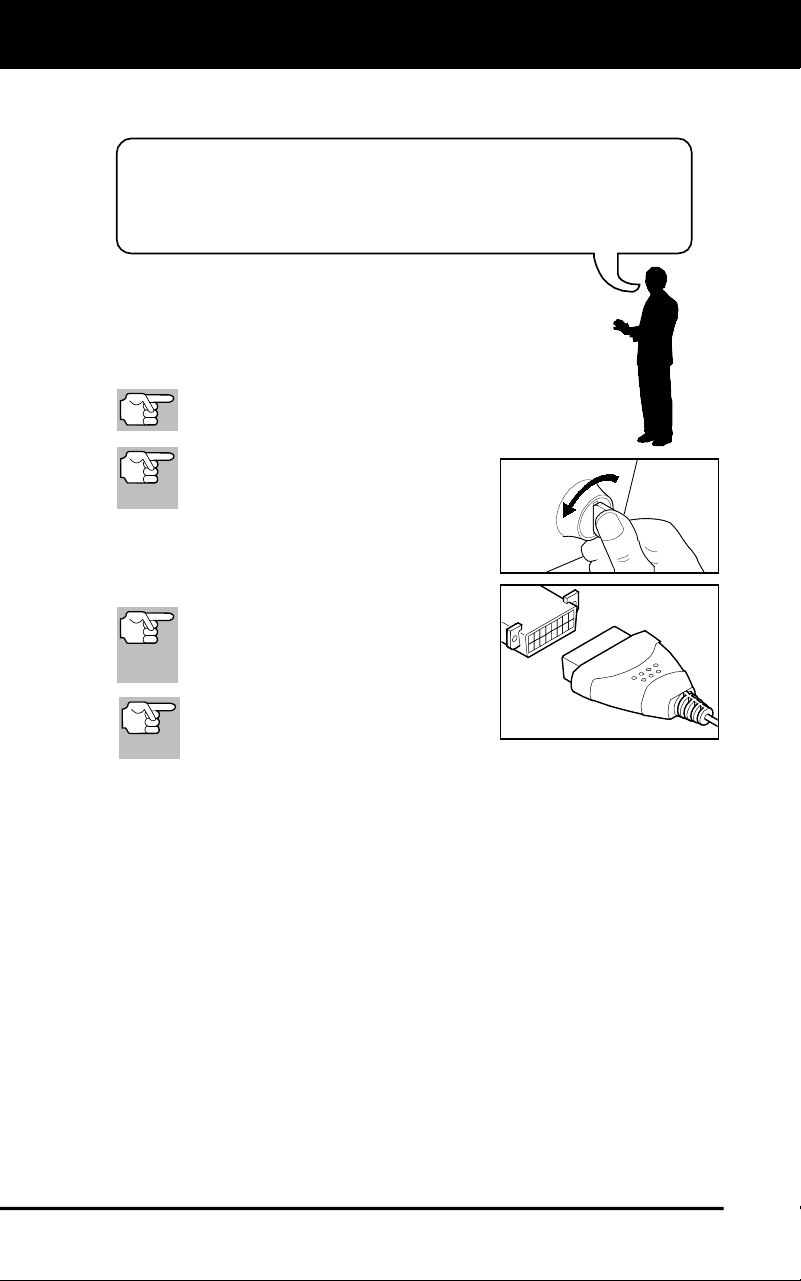
1. Turn the ignition off.
2. Locate the vehicle's 16-pin Data Link
Connector (DLC).
Some DLCs have a plastic cover
that must be removed before
connecting the Scan Tool cable
connector.
If the Scan Tool is ON, turn it OFF
BEFORE connecting the Scan
Tool to the DLC.
3. Connect the Scan Tool to the vehicle’s DLC. The cable connector is
keyed and will only fit one way.
If you have problems connecting the cable connector to the DLC,
rotate the connector 180°.
If you still have problems, check the DLC on the vehicle and on
the Scan Tool.
4. Turn the ignition on. DO NOT start the engine.
5. When the Scan Tool is properly connected to the vehicle’s DLC, the
unit automatically turns ON.
If the unit does not power on automatically, it may indicate there
is no power present at the vehicle’s DLC connector. Check the
fuse panel and replace any burned-out fuses.
If replacing the fuse(s) does not correct the problem, consult
your vehicle’s repair manual to identify the proper computer
(PCM) fuse/circuit, and perform any necessary repairs before
proceeding.
Using the Scan Tool
CODE RETRIEVAL PROCEDURE
25
6. The Scan Tool automatically starts a check of the vehicle’s
computer to determine which type of communication protocol it is
using. When the Scan Tool identifies the computer’s communication
protocol, a communication link is established.
A PROTOCOL is a set of rules and procedures for regulating
data transmission between computers, and between testing
equipment and computers. As of this writing, five different
types of protocols (ISO 9141, Keyword 2000, J1850 PWM,
J1850 VPW and CAN) are in use by vehicle manufacturers.
If the Scan Tool fails to link to the vehicle’s computer, a
“Communication Error” message shows.
- Ensure your vehicle is OBD2 compliant.
- Verify the connection at the DLC, and verify the ignition is ON.
- Turn the ignition OFF, wait 5 seconds, then back ON to reset
the computer.
- Press POWER/LINK
to continue.
If the Scan Tool cannot link to the vehicle’s computer after three
attempts, the message “Contact Technical Support” displays.
- Press the SYSTEM MENU
button to return to the System
Menu.
- Turn the ignition off, and
disconnect the Scan Tool.
- Contact Technical Support for
assistance.
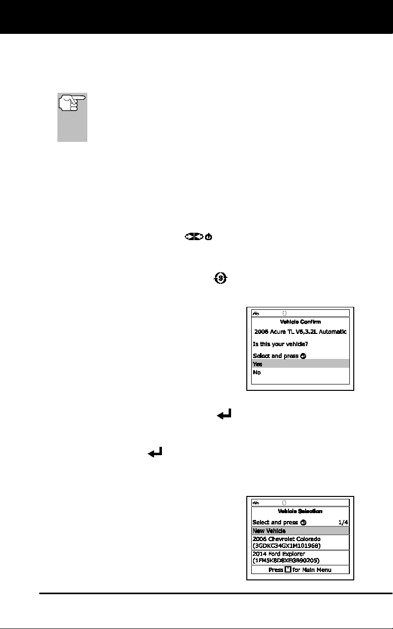
7. If the Scan Tool can decode the Vehicle
Identification Number (VIN) for the
vehicle under test, the Confirm Vehicle
screen displays.
If the information shown is correct for the vehicle under test,
select Yes, then press ENTER
. Proceed to step 10.
If the information shown is not correct for the vehicle under test,
or if you wish to manually select the vehicle, select No, then
press ENTER
. Proceed to step 8.
If the Scan Tool cannot decode the Vehicle Identification
Number (VIN) for the vehicle under test, the Select Vehicle
screen displays. Proceed to step 8.
8. When No is selected from the Vehicle
information screen, the Select Vehicle
screen displays. The Select Vehicle
screen lists the three most recently
tested vehicles.
Using the Scan Tool
CODE RETRIEVAL PROCEDURE
26
To select a previously tested vehicle, select the desired vehicle,
then press ENTER
. Proceed to step 10.
To select a new vehicle, select New
Vehicle, then press ENTER
.
Proceed to step 9.
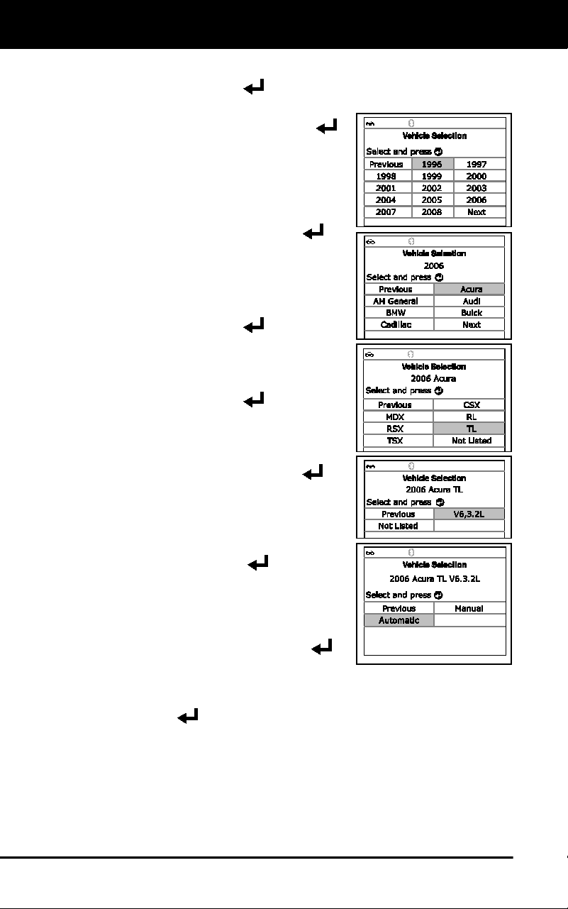
9. When New Vehicle is chosen from the
Select Vehicle screen, the Select Year
screen displays.
Select the desired vehicle model
year, then press ENTER
to
continue.
- The Select Make screen dis-
plays.
Select the desired vehicle make,
then press ENTER
to continue.
- The Select Model screen
displays.
Select the desired vehicle model,
then press ENTER
to continue.
- The Select Engine screen
displays.
Select the desired vehicle engine
size, then press ENTER
to
continue.
- The Select Transmission screen
displays.
Select the desired transmission type,
then press ENTER
to continue.
The Vehicle Information screen
displays.
If the information shown is correct
for the vehicle under test, select
Yes, then press ENTER
.
Proceed to step 10.
If the information shown is not correct for the vehicle under test,
or if you wish to reselect the vehicle, select No, then press
ENTER
to return to the Select Year screen.
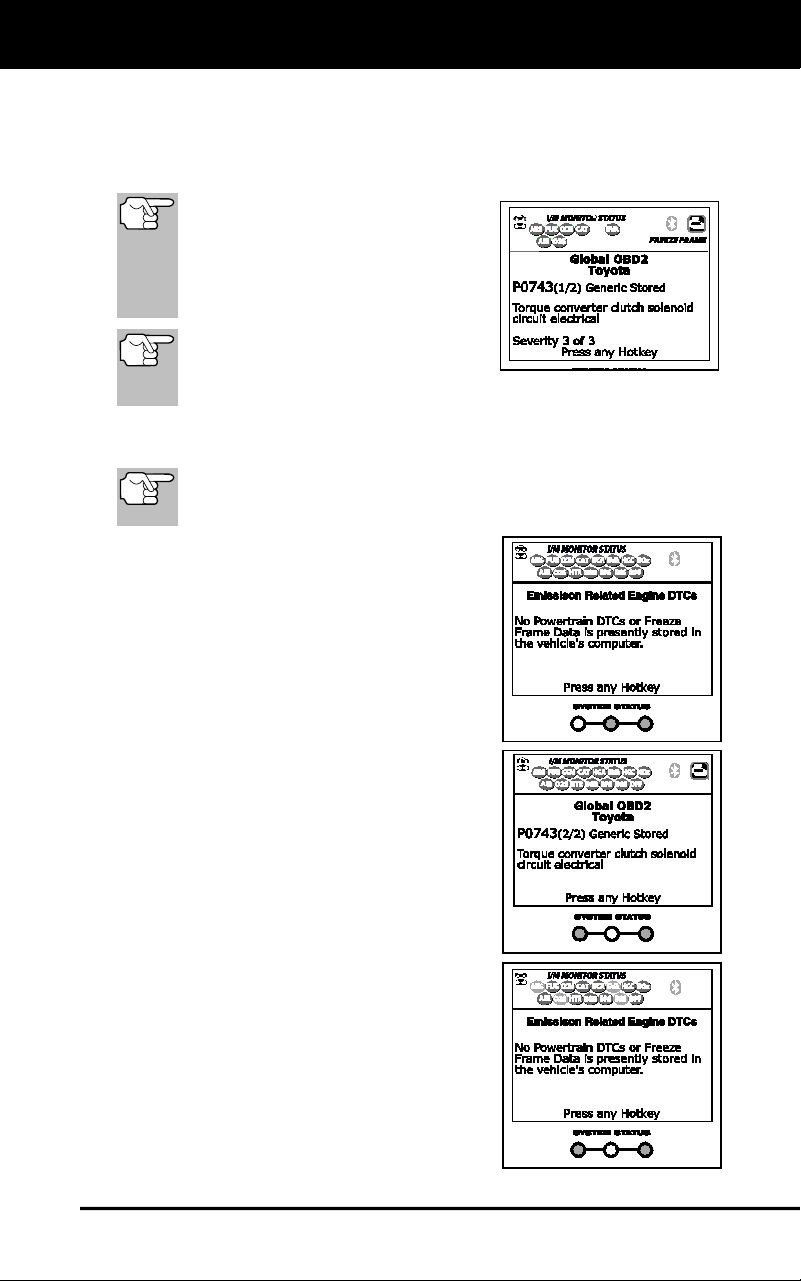
10. After approximately 10~60 seconds, the Scan Tool will retrieve and
display any Diagnostic Trouble Codes, Monitor Status and Freeze
Frame Data retrieved from the vehicle’s computer memory.
The Scan Tool will display a code only if codes are present. If no
codes are present, the message “No Powertrain DTCs or Freeze
Frame Data presently stored in the vehicle’s computer” displays.
Using the Scan Tool
CODE RETRIEVAL PROCEDURE
27
The Scan Tool is capable of retrieving and storing up to 32
codes in memory, for immediate or later viewing.
11. Refer to DISPLAY FUNCTIONS on page 3 for a description of
display elements.
In the case of long code definitions,
a small arrow is shown in the
upper/lower right-hand corner of the
Scan Tool display area to indicate
the presence of additional
information.
If a definition for the currently
displayed code is not available,
an advisory message shows on
the Scan Tool’s display.
12. Read and interpret Diagnostic Trouble Codes/system condition
using the display and the green, yellow and red LEDs.
The green, yellow and red LEDs are used (with the display) as
visual aids to make it easier to determine engine system
conditions.
Green LED – Indicates that all engine
systems are “OK” and operating
normally. All monitors supported by
the vehicle have run and performed
their diagnostic testing, and no trouble
codes are present. All Monitor icons
will be solid.
Yellow LED – Indicates one of the
following conditions:
A. A PENDING CODE IS PRESENT – If
the yellow LED is illuminated, it may
indicate a Pending code is present.
Check the display for confirmation. A
Pending code is confirmed by the
presence of a numeric code and the
word PENDING.
B. MONITOR NOT RUN STATUS – If
the display shows a zero (indicating
there are no DTC’s present in the
vehicle’s computer memory), but the
yellow LED is illuminated, it may be
an indication that some of the
Monitors supported by the vehicle
have not yet run and completed their
diagnostic testing. Check the display
for confirmation. All Monitor icons that
are blinking have not yet run and
completed their diagnostic testing; all
Monitor icons that are solid have run
and completed their diagnostic testing.
Using the Scan Tool
CODE RETRIEVAL PROCEDURE
28
Red LED – Indicates there is a
problem with one or more of the
vehicle’s systems. The red LED is
also used to indicate that DTC(s)
are present. In this case, the
Malfunction Indicator (Check Engine)
lamp on the vehicle’s instrument
panel will be illuminated.
DTC’s that start with “P0”, “P2” and
some “P3” are considered Generic
(Universal). All Generic DTC definitions are the same on all OBD2
equipped vehicles. The Scan Tool automatically displays the code
definitions (if available) for Generic DTC’s.
DTC’s that start with “P1” and some “P3” are Manufacturer specific
codes and their code definitions vary with each vehicle manufacturer.
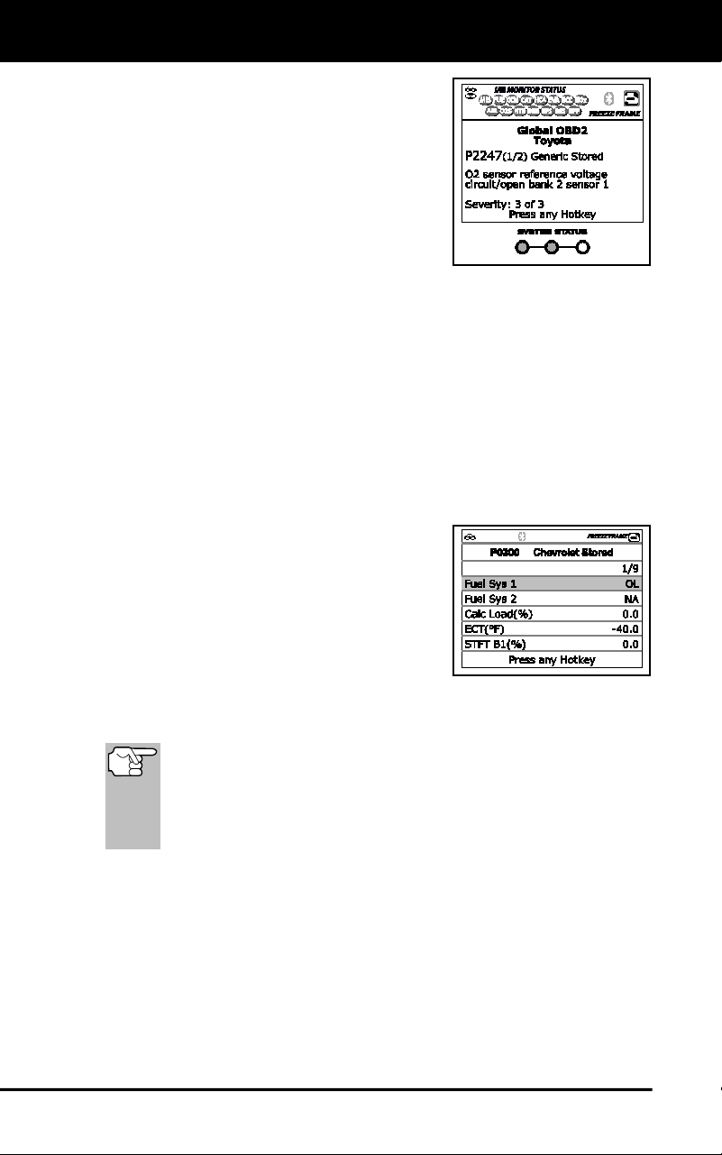
13. If more than one DTC was retrieved, and to view Freeze Frame
Data, press and release DTC/FF as necessary.
Each time DTC/FF is pressed and released, the Scan Tool will
scroll and display the next DTC in sequence until all DTCs in its
memory have displayed.
Freeze Frame Data (if available) will display after DTC #1.
In OBD2 systems, when an
emissions-related engine malfunction
occurs that causes a DTC to set, a
record or snapshot of engine condi-
tions at the time that the malfunction
occurred is also saved in the vehicle’s
computer memory. The record saved
is called Freeze Frame data. Saved
engine conditions include, but are not
limited to: engine speed, open or closed loop operation, fuel system
commands, coolant temperature, calculated load value, fuel
pressure, vehicle speed, air flow rate, and intake manifold pressure.
If more than one malfunction is present that causes more than
one DTC to be set, only the code with the highest priority will
contain Freeze Frame data. The code designated “01” on the
Scan Tool display is referred to as the PRIORITY code, and
Freeze Frame data always refers to this code. The priority
code is also the one that has commanded the MIL on.
14. When the last retrieved DTC has been displayed and DTC/FF is
pressed, the Scan Tool returns to the “Priority” Code.
15. Determine engine system(s) condition by viewing the Scan Tool’s
display for any retrieved Diagnostic Trouble Codes, code definitions and
Freeze Frame data, interpreting the green, yellow and red LEDs.
If DTC’s were retrieved and you are going to perform the repairs
yourself, proceed by consulting the Vehicle’s Service Repair
Manual for testing instructions, testing procedures, and flow
charts related to retrieved code(s).
Using the Diagnostic Tool
THE SYSTEM MENU - VIEWING OEM ENHANCED DTCs (except Ford/Mazda)
29
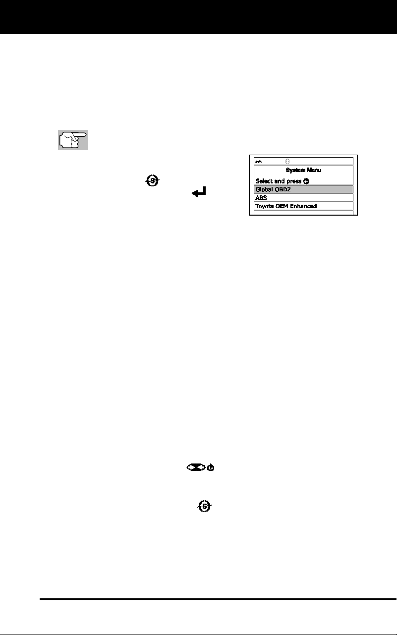
THE SYSTEM MENU
The System Menu provides the ability to retrieve “enhanced” DTCs and
Anti-Lock Brake System (ABS) DTCs for most BMW, Chrysler/Jeep,
Ford/Mazda, GM/Isuzu, Honda/Acura, Hyundai, Mercedes Benz, Nissan,
Toyota/Lexus, Volkswagen and Volvo vehicles. The types of enhanced
data available depends on the vehicle make. You can also return to the
Global OBD2 mode.
Depending on the vehicle under test, some features and functions
may not be available.
To access the System Menu, press
SYSTEM MENU
. Select the desired
option, then press ENTER
to view
the selected information.
To view ABS DTCs: Select ABS from the System Menu. Refer to
VIEWING ABS DTCs on page 32 to view ABS DTCs for your vehicle.
To view SRS DTCs: Select SRS from the System Menu. Refer to
VIEWING SRS DTCs on page 33 to view SRS DTCs for your vehicle.
To view OEM enhanced DTCs: Select OEM Enhanced from the
System Menu. Refer to VIEWING OEM ENHANCED DTCs on page 29
to view OEM enhanced DTCs for your vehicle.
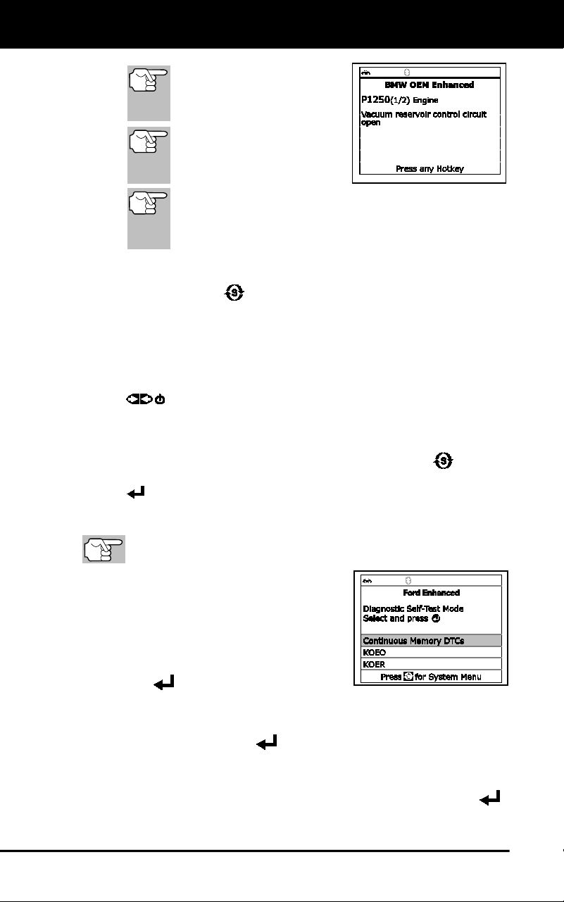
VIEWING OEM ENHANCED DTCs (except Ford/Mazda)
When (make) OEM Enhanced is chosen from the System Menu, the
Scan Tool retrieves OEM enhanced DTCs from the vehicle’s computer.
1. A “One moment please” message displays while the Scan Tool
retrieves the selected DTCs.
If the Scan Tool fails to link to the vehicle’s computer, a
“Communication Error” message shows.
Ensure your vehicle is OBD2 compliant.
- Verify the connection at the DLC, and verify the ignition is ON.
- Turn the ignition OFF, wait 5 seconds, then back ON to reset
the computer.
- Press POWER/LINK
to continue.
If the Scan Tool cannot link to the vehicle’s computer after three
attempts, the message “Contact Technical Support” displays.
- Press SYSTEM MENU
to return to the System Menu.
- Turn the ignition off, and disconnect the Scan Tool.
- Contact Technical Support for assistance.
2. Refer to DISPLAY FUNCTIONS on page 3 for a description of LCD
display elements.
Using the Diagnostic Tool
VIEWING OEM ENHANCED DTCs (Ford/Mazda only)
30
If the definition for the cur-
rently displayed code is not
available, an advisory mes-
sage shows.
I/M MONITOR STATUS
icons are not displayed
when viewing enhanced
DTCs.
In the case of long code definitions, a small arrow is
shown in the upper/lower right-hand corner of the code
display area to indicate the presence of additional
information.
If no codes are present, the message “No OEM Enhanced DTC’s
are presently stored in the vehicle’s computer” shows. Press
SYSTEM MENU
to return to the System Menu.
3. If more than one code was retrieved press DTC/FF, as necessary,
to display additional codes one at a time.
Whenever the Scroll function is used to view additional codes, the
Scan Tool’s communication link with the vehicle’s computer
disconnects. To re-establish communication, press POWER/LINK
again.
4. When the last retrieved DTC has been displayed and DTC/FF is
pressed, the Scan Tool returns to the “Priority” Code.
To exit the enhanced mode, press SYSTEM MENU to return
to the System Menu. Select Global OBD, then press ENTER
to return to the Global OBD2 mode.
VIEWING OEM ENHANCED DTCs (Ford/Mazda only)
Mazda Enhanced DTCs are available for Mazda-branded
Ford vehicles only.
When Ford OEM Enhanced is chosen from
the System Menu, the Ford Enhanced
menu displays. You may view OEM DTCs
for either the “Continuous Memory Test”,
“KOEO (Key On Engine Off) Test” or
“KOER (Key On Engine Running) Test.”
1. Select the desired option, then press
ENTER
.
If KOER is selected, an advisory message shows.
- Start and warm the engine to normal operating temperature,
then press ENTER
. Proceed to step 3.
2. If KOEO or Continuous Memory is selected, an “instructional”
message shows.
Turn the ignition OFF, then back ON. Press ENTER .
Proceed to step 3.
Using the Scan Tool
VIEWING OEM ENHANCED DTCs (Ford/Mazda only)
31
3. A “One moment please” message displays while the test is in
progress.
If the Scan Tool fails to link to the vehicle’s computer, a
“Communication Error” message shows.
- Ensure your vehicle is OBD2 compliant.
- Verify the connection at the DLC, and verify the ignition is ON.
- Turn the ignition OFF, wait 5 seconds, then back ON to reset
the computer.
- Press POWER/LINK
to continue.
If the Scan Tool cannot link to the vehicle’s computer after three
attempts, the message “Contact Technical Support” displays.
- Press SYSTEM MENU
to return to the System Menu.
- Turn the ignition off, and disconnect the Scan Tool.
- Contact Technical Support for assistance.
If the KOER Test was selected, and the vehicle’s engine is not
running, an advisory message shows.
- Start the engine and press ENTER
to try again, or, press
SYSTEM MENU
to return to the System Menu.
If the KOEO Test was selected, and the vehicle’s engine is
running, an advisory message shows.
- Turn the ignition OFF then back ON and press ENTER
to
try again, or, press SYSTEM MENU
to return to the System
Menu.
4. If the KOER test was selected, an “instructional” message shows.
Turn the steering wheel to the left, then release.
Press and release the brake pedal.
Cycle the overdrive switch (if equipped).
A “One moment please” message displays while the test is in
progress.
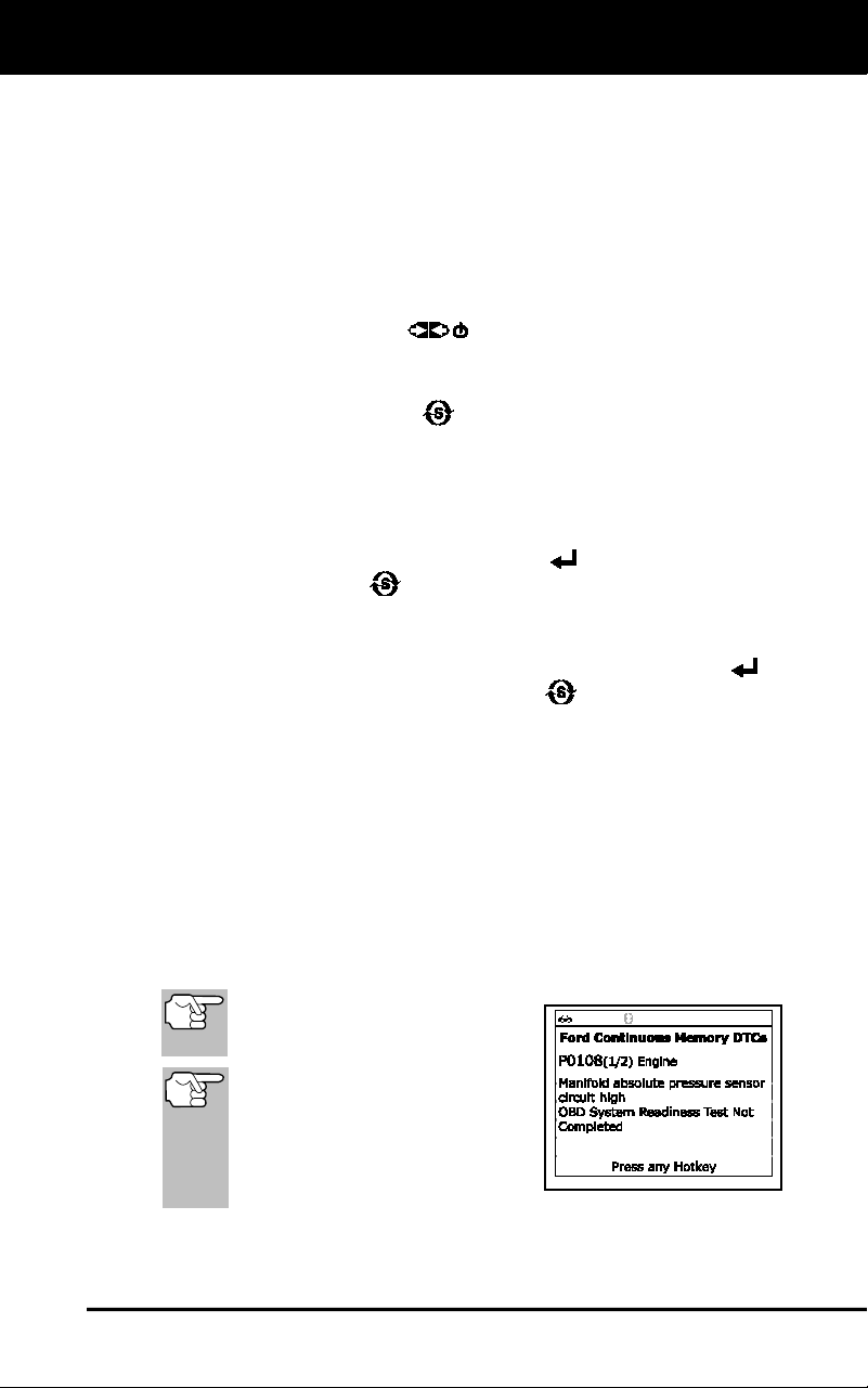
5. Refer to DISPLAY FUNCTIONS on page 3 for a description of LCD
display elements.
I/M MONITOR STATUS icons
are not displayed when
viewing enhanced DTCs.
In the case of long code
definitions, a small arrow is
shown in the upper/ lower right-
hand corner of the code display
area to indicate the presence
of additional information.
Using the Diagnostic Tool
VIEWING ABS DTCs
32
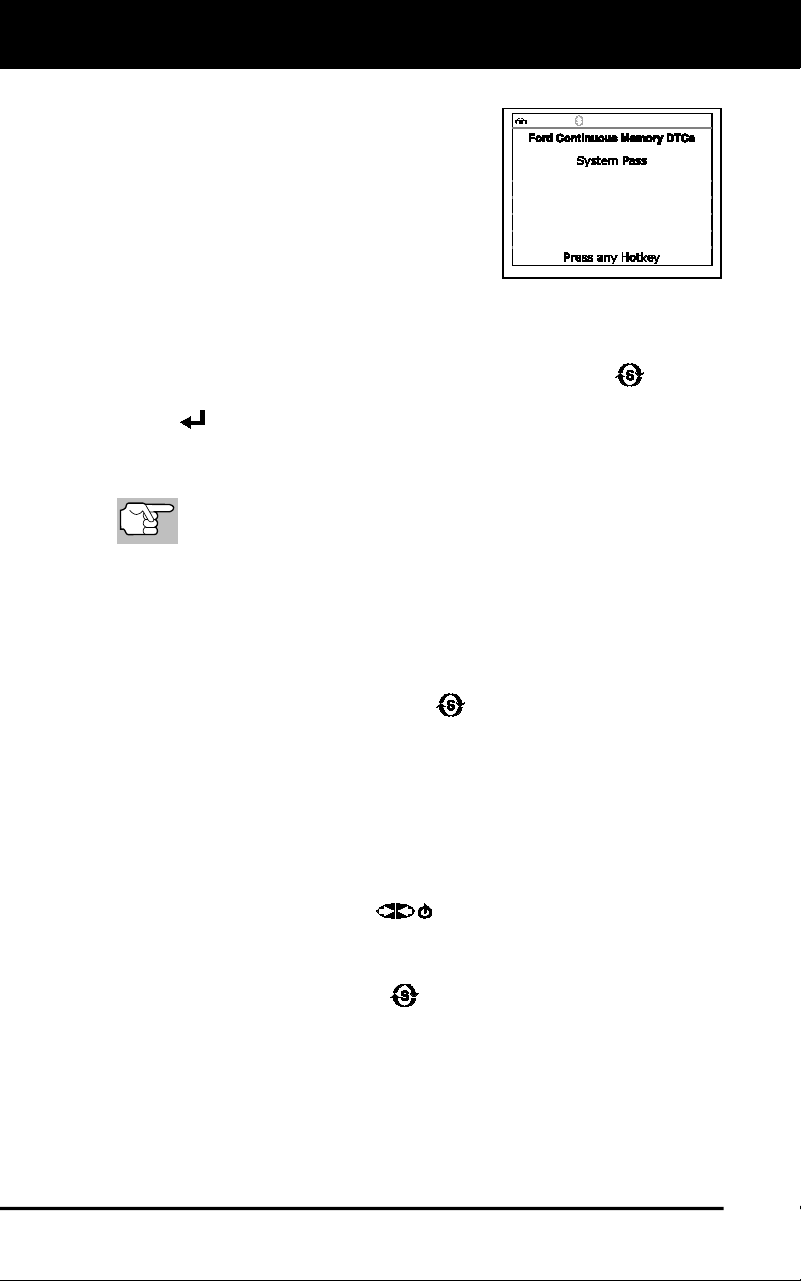
If no codes are present, a “System
Pass” message displays. Press any
Hotkey.
6. If more than one code was retrieved
press DTC/FF to display additional
codes one at a time.
7. When the last retrieved DTC has been
displayed and DTC/FF is pressed, the
Scan Tool returns to the “Priority” Code.
To view additional enhanced DTCs, repeat steps 1 through 5,
above.
To exit the enhanced mode, press SYSTEM MENU to return
to the System Menu. Select Global OBD, then press ENTER
to return to the Global OBD2 mode.
VIEWING ABS DTCs
Refer to the manufacturer’s website for vehicle makes covered.
Reading ABS DTCs
1. When ABS is chosen from the System Menu, a "One moment
please" message displays while the Scan Tool retrieves the selected
DTCs.
If ABS functionality is not supported, an advisory message
shows. Press SYSTEM MENU
to return to the System Menu.
If the Scan Tool fails to link to the vehicle’s computer, a
"Communication Error" message shows.
- Ensure your vehicle is OBD2 compliant.
- Verify the connection at the DLC, and verify the ignition is ON.
- Turn the ignition OFF, wait 5 seconds, then back ON to reset
the computer.
- Press POWER/LINK
to continue.
If the Scan Tool cannot link to the vehicle’s computer after three
attempts, the message “Contact Technical Support” displays.
- Press SYSTEM MENU
to return to the System Menu.
- Turn the ignition off, and disconnect the Scan Tool.
- Contact Technical Support for assistance.
2. Refer to DISPLAY FUNCTIONS on page 3 for a description of LCD
display elements.
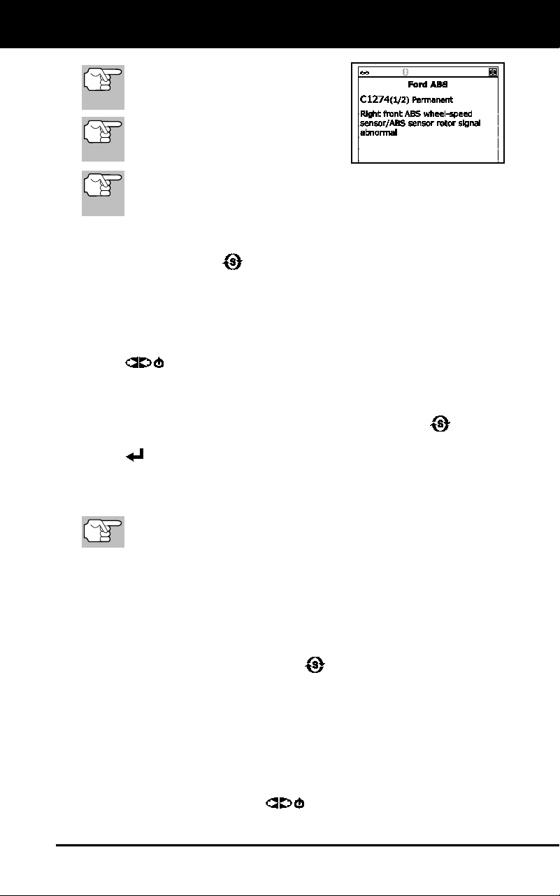
Using the Scan Tool
VIEWING SRS DTCs
33
If the definition for the currently
displayed code is not available, an
advisory message shows.
I/M MONITOR STATUS icons are
not displayed when viewing ABS
DTCs.
In the case of long code definitions, a small arrow is shown in
the upper/lower right-hand corner of the code display area to
indicate the presence of additional information.
If no codes are present, the message "No ABS DTC’s are
presently stored in the vehicle’s computer" shows. Press
SYSTEM MENU
to return to the System Menu.
3. If more than one code was retrieved press DTC/FF to display
additional codes one at a time.
Whenever the Scroll function is used to view additional codes, the
Scan Tool’s communication link with the vehicle’s computer
disconnects. To re-establish communication, press POWER/LINK
again.
4. When the last retrieved DTC has been displayed and DTC/FF is
pressed, the Scan Tool returns to the “Priority” Code.
To exit the enhanced mode, press SYSTEM MENU to return
to the System Menu. Select Global OBD, then press ENTER
to return to the Global OBD2 mode.
VIEWING SRS DTCs
Refer to the manufacturer’s website for vehicle makes covered.
Reading SRS DTCs
1. When SRS is chosen from the System Menu, a "One moment
please" message displays while the Scan Tool retrieves the selected
DTCs.
If SRS functionality is not supported, an advisory message
shows. Press SYSTEM MENU
to return to the System Menu.
If the Scan Tool fails to link to the vehicle’s computer, a
"Communication Error" message shows.
- Ensure your vehicle is OBD2 compliant.
- Verify the connection at the DLC, and verify the ignition is ON.
- Turn the ignition OFF, wait 5 seconds, then back ON to reset
the computer.
- Press POWER/LINK
to continue.
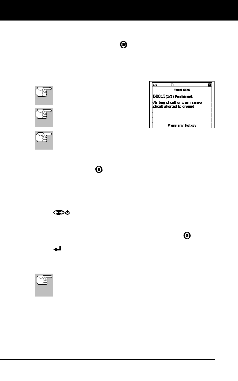
Using the Scan Tool
ERASING DIAGNOSTIC TROUBLE CODES (DTCs)
34
If the Scan Tool cannot link to the vehicle’s computer after three
attempts, the message “Contact Technical Support” displays.
- Press SYSTEM MENU
to return to the System Menu.
- Turn the ignition off, and disconnect the Scan Tool.
- Contact Technical Support for assistance.
2. Refer to DISPLAY FUNCTIONS on page 4 for a description of LCD
display elements.
If the definition for the currently
displayed code is not available, an
advisory message shows
I/M MONITOR STATUS icons are
not displayed when viewing SRS
DTCs.
In the case of long code definitions, a small arrow is shown in
the upper/lower right-hand corner of the code display area to
indicate the presence of additional information.
If no codes are present, the message "No SRS DTC’s are
presently stored in the vehicle’s computer" shows. Press
SYSTEM MENU
to return to the System Menu.
3. If more than one code was retrieved press DTC to display additional
codes one at a time.
Whenever the Scroll function is used to view additional codes, the
Scan Tool’s communication link with the vehicle’s computer
disconnects. To re-establish communication, press POWER/LINK
again.
4. When the last retrieved DTC has been displayed and DTC/FF is
pressed, the Scan Tool returns to the “Priority” code.
To exit the enhanced mode, press SYSTEM MENU to return
to the System Menu. Select Global OBD, then press ENTER
to return to the Global OBD2 mode.
ERASING DIAGNOSTIC TROUBLE CODES (DTCs)
When the Scan Tool’s ERASE function is used to erase DTCs
from the vehicle's on-board computer, "Freeze Frame" data
and manufacturer-specific-enhanced data are also erased.
"Permanent" DTCs ARE NOT erased by the ERASE function.
If you plan to take the vehicle to a Service Center for repair, DO NOT
erase the codes from the vehicle's computer. If the codes are erased,
valuable information that might help the technician troubleshoot the
problem will also be erased.
Erase DTCs from the computer's memory as follows:
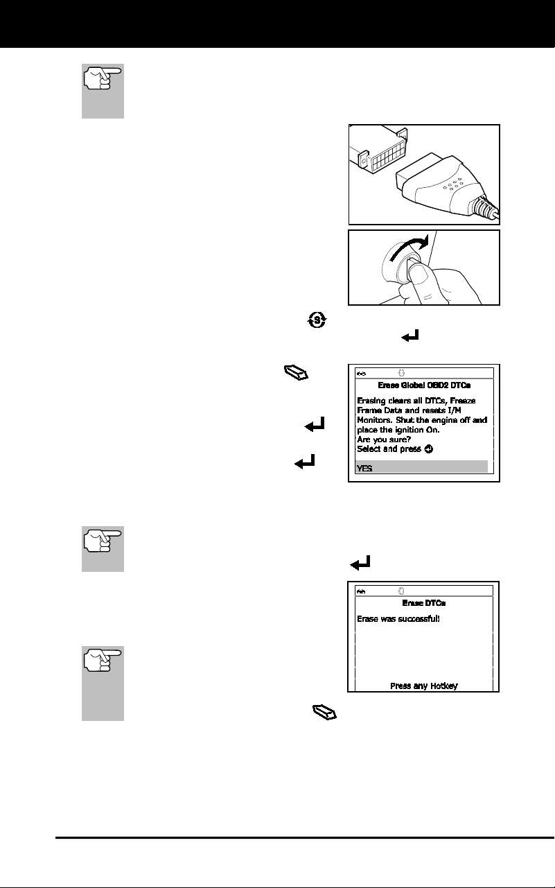
Using the Scan Tool
ERASING DIAGNOSTIC TROUBLE CODES (DTCs)
35
When DTCs are erased, the I/M Readiness Monitor Status
program resets the status of all Monitors to a not run condition. To
set all Monitors to a DONE status, an OBD2 Drive Cycle must be
performed.
1. If not connected already, connect the
Scan Tool to the vehicle's DLC, and
turn the ignition "On.” (If the Scan Tool
is already connected and linked to the
vehicle's computer, proceed directly to
step 3. If not, continue to step 2.)
2. Perform the Code Retrieval procedure
as described on page 24.
To erase OBD2 DTCs: Wait until
the codes are displayed, then
proceed to step 3.
To erase enhanced, ABS or SRS
DTCs: Press SYSTEM MENU
to display the System Menu.
Select the desired option, then press ENTER
. Perform the
appropriate Code Retrieval procedure and then proceed to step 3.
3. Press and release ERASE
. A
confirmation message shows.
If you are sure you want to proceed,
select Yes, then press ENTER
.
If you do not want to proceed, select
No, then press ENTER
to
cancel the erase procedure.
4. If you chose to erase DTCs, a “One moment please…” message
displays while the erase function is in progress.
If the vehicle’s engine is running, an advisory message shows.
Turn the engine OFF, then turn the ignition back to ON. DO
NOT start the engine. Press ENTER
to continue.
If the erase was successful, a
confirmation message shows. The
Scan Tool automatically relinks to the
vehicle’s computer after 3 seconds.
If the erase was not successful and
ECU error code $22 is present, an
advisory message displays. Start
the engine and maintain vehicle
speed at 0, then press ERASE
to try again.
If the erase was not successful, an advisory message shows
indicating the erase request was sent to the vehicle’s computer.
The Scan Tool automatically relinks to the vehicle’s computer
after 3 seconds.

Using the Scan Tool
ABOUT REPAIRSOLUTIONS®
36
Erasing DTCs does not fix the problem(s) that caused the
code(s) to be set. If proper repairs to correct the problem that
caused the code(s) to be set are not made, the code(s) will
appear again (and the Check Engine Light will illuminate) as
soon as the vehicle is driven long enough for its Monitors to
complete their testing.
ABOUT REPAIRSOLUTIONS®
RepairSolutions 2® is a web-based service created to assist both Do-It-
Yourself and Professional technicians in quickly and accurately
diagnosing and repairing today’s vehicles. RepairSolutions 2 allows you
to view and save the diagnostic data retrieved from a vehicle’s on-board
computer(s) using your Code Reader. At the core of RepairSolutions 2
is an extensive knowledge database, developed by compiling and
analyzing years worth of “real world” vehicle service data.
RepairSolutions 2 builds on manufacturer-recommended diagnostic and
repair information by providing verified, vehicle-specific fixes supplied by
ASE technicians across the country. RepairSolutions 2 also provides
access to an extensive knowledge database including:
Verified Fixes – Find the most likely fixes reported and verified by
ASE Technicians for the retrieved DTCs.
Repair Instructions – View available repair instructions to properly
perform the fix.
Video Tutorials – Watch repair video tutorials for valuable repair
tips.
Technical Service Bulletins – Research known problems reported
by vehicle manufacturers.
Safety Recalls – Research known safety concerns applicable to a
vehicle.
And much more. Please visit www.innova.com for additional information.
Hardware Requirements:
Innova Scan Tool with Bluetooth/WiFi
Android or iOS Smart Device
Accessing RepairSolutions 2®
1. Download and install the RepairSolutions 2® app from the App
Store (for iOS devices) or Google Play (for Android devices).
2. Launch the RepairSolutions 2 app and log in to your account.
If you have not yet established an account, you must register for
a FREE RepairSolutions 2 account before proceeding.
Connect the Code Reader to a vehicle and establish a Bluetooth
or WiFi connection with your Smart Device (refer to
CONNECTING TO BLUETOOTH / WIFI, below). Be sure your
Smart Device is connected to an available WiFi network.

Using the Scan Tool
CONNECTING TO BLUETOOTH / WIFI
37
The RepairSolutions 2 app will store two WiFi configurations
only.
3. Retrieve diagnostic data (refer to CODE RETRIEVAL PROCEDURE
on page 24 for details).
4. The RepairSolutions 2 app automatically displays a report based on
the retrieved diagnostic data.
If the Code Reader is not connected to WiFi or Bluetooth,
vehicle data will not be saved.
CONNECTING TO BLUETOOTH / WIFI
Launch the RepairSolutions2 app and follow the prompts to establish
Bluetooth and (optionally) WiFi connections, as follows:
1. Launch the RepairSolutions2 app. Select Wifi Tools Settings from
the menu. Power on your Code Reader, then select from the list of
available devices.
2. When Bluetooth pairing is complete, a confirmation screen displays.
Click Continue.
If a Bluetooth connection cannot be established, an advisory
message displays. Tap Try Again to repeat the pairing process.
3. Follow the on-screen prompts to connect to an available WiFi
network.
You can automatically connect to the network your Smart Device
is currently connected to, or you can manually connect to
another available network.
Note that only 2.4GHz networks are supported.
If you do not wish to connect to a WiFi network at this time, tap
SKIP.
4. When WiFi pairing is complete, a confirmation screen displays. Click
Continue to view the “Setup Complete” message, then click
Continue to enter RepairSolutions2.
If a WiFi connection cannot be established, an advisory
message displays. Tap Try Again to repeat the pairing process.
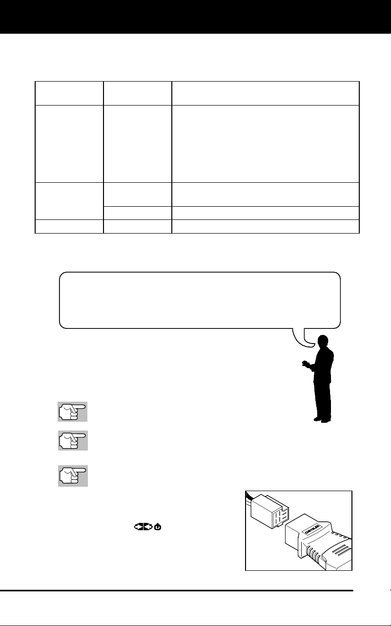
Chrysler/Jeep OBD1 Systems
VEHICLES COVERED - CODE RETRIEVAL PROCEDURE
38
Retrieving and using Diagnostic Trouble Codes (DTCs) for
troubleshooting vehicle operation is only one part of an
overall diagnostic strategy.
VEHICLES COVERED
This section covers Chrysler fuel injected vehicles from 1989-1995.
Type
Model
Year
Model
Passenger
Cars
1989-1994
Chrysler, Dodge and Plymouth Fuel
Injected Models Only (Excluding
Lasor/Talon 1.8L, 2.0L (ALL YEARS), 1990
Monaco/Premier, 1993-1995 Intrepid, LHS,
Concorde and Vision, 1995 Avenger,
Stealth (ALL YEARS) and Cirrus 2.5L (ALL
YEARS))
Light Truck
and Vans
1989-1995
Chrysler, Dodge and Plymouth Fuel
Injected Models Only
1992-1995
Diesel Models
Jeep
1993-1995
Jeep Fuel Injected Models Only
CODE RETRIEVAL PROCEDURE
Never replace a part based only on
the DTC definition. Each DTC has a set of testing
procedures, instructions and flow charts that must be
followed to confirm the location of the problem. Always
refer to the vehicle’s service manual for detailed testing
instructions.
Check your vehicle thoroughly before performing
any test.
ALWAYS observe safety precautions whenever working on a
vehicle.
1. Locate the vehicle’s Data Link Connector (DLC).
Some DLCs have a plastic cover that must be removed before
connecting the Scan Tool.
2. Connect the Scan Tool (with the
Chrysler Connector Cable Adaptor
attached) to the vehicle’s DLC. Press
POWER/LINK
to turn the Scan
Tool ON.
Set the parking brake, and make
sure all vehicle accessories are
turned off.
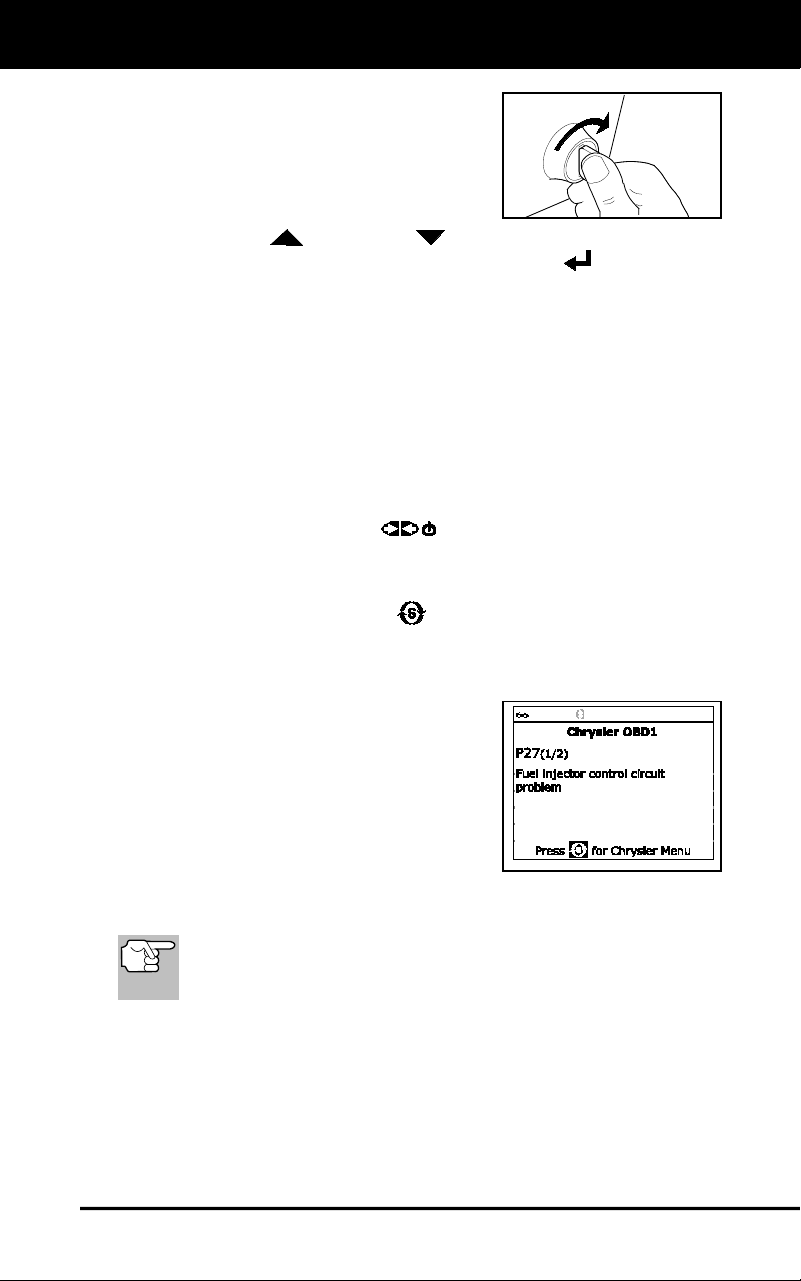
Chrysler/Jeep OBD1 Systems
CODE RETRIEVAL PROCEDURE
39
3. Turn the ignition ON. DO NOT start the
engine.
The Chrysler Menu displays.
4. To retrieve codes from the vehicle’s
computer:
Press UP and DOWN , as necessary, to highlight the
model year of the vehicle, then press ENTER
.
5. A “One moment please…” message shows while codes are being
retrieved.
If the Scan Tool fails to link to the vehicle’s computer, a “Commu-
nication Error” message.
- Verify the ignition is ON.
- Check the cable connections at the Scan Tool and at the
vehicle’s DLC.
- Turn the ignition OFF, wait 10-12 seconds, then turn back ON
to reset the computer.
- Press POWER/LINK
to continue.
If the Scan Tool cannot link to the vehicle’s computer after three
attempts, the message “Contact Technical Support” displays.
- Press SYSTEM MENU
to return to the Chrysler Menu.
- Turn the ignition off, and disconnect the Scan Tool.
- Contact Technical Support for assistance.
6. If the Scan Tool was able to link to the
vehicle successfully, the Tool displays
the retrieved DTCs.
The Scan Tool will display a code only
if codes are present. If no codes are
present, the message “No DTCs are
presently stored in the vehicle’s
computer” displays.
7. If more than one code was retrieved press DTC/FF, as necessary,
to display additional codes one at a time.
In the case of long code definitions, a small arrow is shown in
the upper/lower right-hand corner of the code display area to
indicate the presence of additional information.
8. Disconnect the Scan Tool from the vehicle and turn the ignition key
OFF.
9. To prolong battery life, the Scan Tool automatically shuts "Off" after
approximately three minutes of no button activity. The DTCs
retrieved will remain in the Scan Tool's memory, and may be viewed
at any time. If the Scan Tool’s batteries are removed, or if the Scan
Tool is re-linked to a vehicle to retrieve codes, any prior codes in its
memory are automatically cleared.
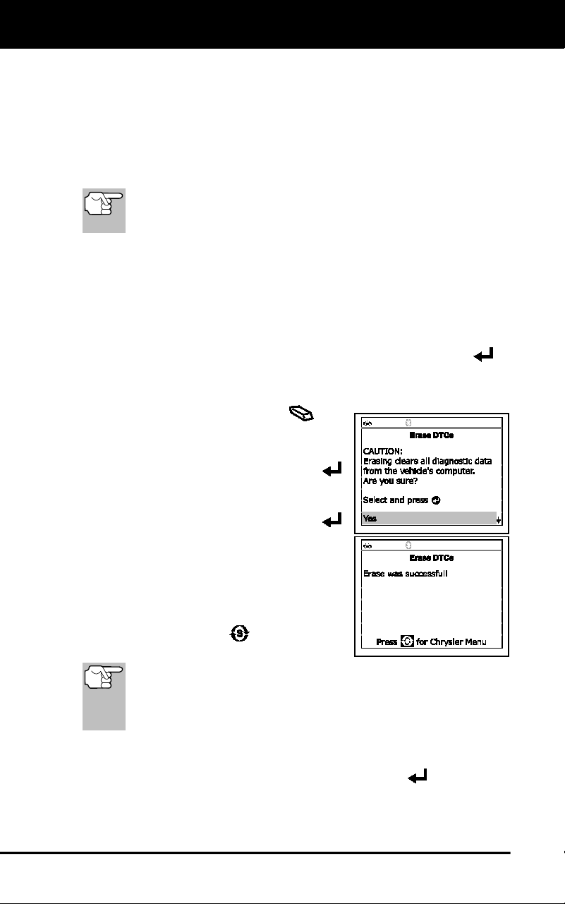
Chrysler/Jeep OBD1 Systems
ERASING DTCs
40
10. Follow the testing and repair procedures outlined in the vehicle's
service repair manual to correct "hard" DTCs. Codes should be
addressed and eliminated in the order they were received, erasing
and retesting after each repair is made to be sure the fault was
eliminated.
ERASING DTCs
When the Scan Tool's ERASE function is used to erase DTCs
from the vehicle's on-board computer, manufacturer specific
data (where applicable) is also erased.
If you plan to take the vehicle to a service center for repair, DO NOT
erase the codes from the vehicle's computer. If the codes are erased,
valuable information that might help the technician troubleshoot the
problem will also be erased.
Erase DTC’s from the computer’s memory as follows:
1. Connect the Scan Tool to the vehicle’s DLC. Press ENTER to
continue.
2. Turn the ignition ON. DO NOT start the engine.
3. Press and release ERASE
. A
confirmation message shows.
If you are sure you want to proceed,
select Yes, then press ENTER
to continue.
If you do not want to proceed,
select No, then press ENTER
to exit the erase function.
4. If you chose to erase DTCs, a “One
moment please…” message displays
while the erase function is in progress.
If the erase was successful, a
confirmation message shows. Press
SYSTEM MENU
to return to the
Chrysler Menu.
The Scan Tool can be used to erase codes for some vehicles,
while others require codes to be erased manually. If the “This
vehicle does not support this function.” screen displays,
consult the vehicle’s service repair manual for procedures to
erase DTCs.
If the erase was not successful, an advisory message shows.
Verify that the Scan Tool is properly connected to the vehicle's
DLC and that the ignition is ON. Press ENTER
to continue. If
the erase process still does not complete, turn the ignition OFF,
wait 10 seconds, then turn back ON and repeat steps 2 and 3.

Chrysler/Jeep OBD1 Systems
ERASING DTCs
41
Erasing DTCs does not fix the problem(s) that caused the
code(s) to be set. If proper repairs to correct the problem that
caused the code(s) to be set are not made, the code(s) will
appear again and the check engine light will illuminate as soon
as the problem that cause the DTC to set manifests itself.
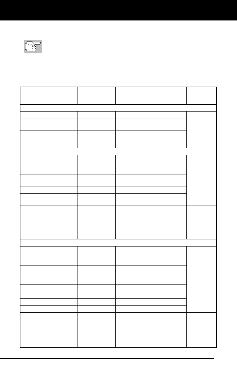
Ford OBD1 Systems
FORD COMPUTER SYSTEM OVERVIEW - VEHICLES COVERED
42
VEHICLES COVERED
The Scan Tool is compatible only with EEC-IV Computer Control
systems.
CAR - Ford, Lincoln, Mercury Computer System/Scan Tool
Application Table
The following table lists the year and model of all the cars that are
covered by the Scan Tool.
Engine
8th
VIN
Digit**
Fuel Systems
(Carburetor
Model)
Application/Special Notes
Computer
System
1981-1982
1.6L I-4
5, 2
EFI, EFI Turbo
Escort, EXP, LN7, Lynx
EEC-IV
2.3L I-4 5 EFI Turbo
Capri, Cougar, Mustang, T-
Bird
2.3L I-4 HSC R, J FBC (6149)*
Capri, Fairmont, LTD, Marquis,
Mustang, Tempo, Topaz,
Zephyr
1984-1986
1.6L I-4
4, 5, 8
EFI EFI Turbo
Escort, EXP, Lynx
EEC-IV
2.3L I-4
2.3L I-4 OHC
A, J, R
FBC
(YFA)* (6149)*
Capri, Cougar, LTD, Marquis,
Mustang, Tempo, Topaz
2.3L I-4 T, W EFI Turbo
Capri, Cougar, Merkur XR4Ti,
Mustang, T-Bird
2.3L I-4 HSC
S, X
CFI
Tempo, Topaz
3.8L V-6 3 CFI
Capri, Cougar, LTD, Marquis,
Mustang, T-Bird
5.0L V-8 F, M CFI, SEFI
Capri, Continental, Colony
Park, Cougar, Country Squire,
Crown Victoria, Grand
Marquis, LTD, Mark VII,
Marquis, Mustang, T-Bird,
Town Car
EEC-IV
1987-1993
1.9L I-4
J, 9
EFI, CFI, SFI
Escort, EXP, Lynx, Tracer
EEC-IV
2.0L I-4 A SEFI
Probe (1993 manual
transmission only)
2.3L I-4 A FBC (YFA)*
Capri, LTD, Marquis, Mustang
(1996 models)
2.3L I-4 OHC
A, M
EFI
Mustang
2.3L I-4
T, W
EFI Turbo
Capri, Cougar, Merkur,
Mustang, T-Bird, XR4Ti
2.3L I-4 HSC
S, X
CFI, EFI, SEFI
Tempo, Topaz
2.5L I-4
D
EFI, CFI
Sable, Taurus
3.0L V-6
3.0L V-6 SHO
1, U, Y
EFI, SEFI, SFI
Probe, Sable, Taurus, Tempo,
Topaz (VIN 1 Taurus models
are Flexible Fuel)
3.8L V-6
3, 4, C,
R
CFI, EFI, SFI
Capri, Continental, Cougar,
LTD, Marquis, Mustang, Sable,
T-Bird,Taurus
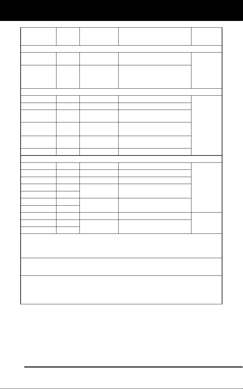
Ford OBD1 Systems
VEHICLES COVERED - CARS
43
Engine
8th
VIN
Digit**
Fuel Systems
(Carburetor
Model)
Application/Special Notes
Computer
System
1987-1993 (Cont)
4.6L V-8
W, V
SEFI
Crown Victoria, Grand
Marquis, Mark VII, Town Car
5.0L V-8
F, M,
E, T,
D, 4
SEFI
Capri, Continental, Cougar,
Crown Victoria, Grand Marquis,
Mark VII, Mustang, Mustang
Cobra, T-Bird, Town Car
1994
1.9L I-4
J
SFI
Escort, Topaz, Tracer
EEC-IV
2.0L I-4
A
SFI
Probe
3.0L V-6 1, U, Y SFI
Sable, Taurus, Tempo (VIN 1
Taurus models are Flexible Fuel)
3.8L V-6
3.8L V-6 SC
4
R
SFI
Continental, Cougar, Sable,
Taurus, T-Bird
4.6L V-8 W, V SFI
Crown Victoria, Grand
Marquis, Mark VIII, Town Car
5.0L V-8
T, D
SFI
Mustang, Mustang Cobra
1995
1.9L I-4
J
SFI
Escort, Tracer
EEC-IV
2.0L I-4
A, 3
SFI
Contour, Mystique, Probe
2.5L V-6
L
SFI
Contour, Mystique
3.0L V-6
1, U
SFI
Sable, Taurus (VIN 1 Taurus
models are Flexible Fuel)
3.0L V-6 SHO
Y
3.8L V-6
4
SFI
Cougar, Sable, Taurus, T-Bird
3.8L V-6 SC
R
4.6L V8 DOHC
V
SFI
Mark VIII
EEC-IV
5.0L V-8 HO
T
SFI Mustang
5.0L V-8 SHP
D
NOTES
* Carburetor Model. Carburetor model numbers are usually stamped on top of the
carburetor, or on a metal tab attached to the carburetor. Consult your vehicle’s repair manual
for proper identification.
**VIN Number. The VIN number(s) used in this column identify the vehicle’s engine type.
This number is the 8th digit of the VIN (Vehicle Identification Number). Consult your vehicle’s
repair manual for details.
Application Table Definitions. CFI = Central Fuel Injection; DOHC = Dual Overhead Cam;
EFI = Electronic Fuel Injection; FBC = Feedback Carburetor; HSC = High Swirl Combustion;
MFI = Multiport Fuel Injection; OHC = Overhead Cam; SC = Super Charged; SEFI =
Sequential Electronic Fuel Injection; SFI = Sequential Fuel Injection; SHO = Super High
Output
TRUCKS/VANS - Ford Computer System/Scan Tool Application Table
The following table lists the year and model of all the trucks and vans
that are covered by the Scan Tool.
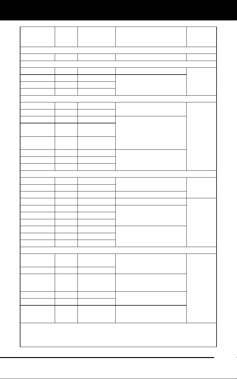
Ford OBD1 Systems
VEHICLES COVERED - TRUCKS/VANS
44
Engine
8th
VIN
Digit**
Fuel Systems
(Carburetor
Model)
Application/Special Notes
Computer
System
1983
2.8L V-6 S FBC (2150A)* Bronco II and Ranger Pickup EEC-IV
1984
2.8L V-6
S
FBC (2150A)*
Bronco II, Ranger Pickup
EEC-IV
4.9L I-6
Y
FBC (YFA)*
Bronco, E and F Series
Trucks/Vans (8500 lb. GVW or
less only)
5.0L V-8
F
FBC (2150A)*
5.8L V-8
G
FBC (2150A)*
1985-1990
2.3L I-4 OHC
A
EFI
Aerostar, Bronco II, Ranger
(excluding Diesel)
EEC-IV
2.9L V-6
T
EFI
2.8L V-6
S
FBC (2150A)*
Bronco, E and F Series
Trucks/Vans (8500 lb. GVW or
less only)
4.9L I-6 Y, 9
FBC (YFA)*,
EFI
5.0L V-8
5.0L V-8
F
N
FBC (2150A)*
EFI
5.8L V-8
G
FBC (2150A)*
E and F Series Trucks/Vans
(8500 lb. GVW or less only)
7.3L V-8
M
Diesel
7.5L V-8
G
EFI
1991-1994
2.3L I-4 OHC
A
EFI, MFI
Ranger
EEC-IV
2.9L V-6
T
EFI
3.0L V-6
U
EFI, SEFI, SFI
Aerostar, Ranger
4.0L V-6
X
EFI, MFI
Aerostar, Explorer, Ranger
EEC-IV
4.9L I-6
Y, H
EFI, MFI, SFI
Bronco, E and F Series
Trucks/Vans (8500 lb. GVW or
less only)
5.0L V-8
N
EFI, MFI, SFI
5.8L V-8
H, R
EFI, MFI, SFI
7.3L V-8
M
Diesel
E and F Series Trucks/Vans
(Excludes 1994 diesel models)
7.3L V-8
K
Turbo Diesel
7.5L V-8
G
EFI, MFI
1995
3.0L V-6
U
SFI
Aerostar (Excludes Explorer,
Ranger and Windstar)
EEC-IV
4.0L V-6
X
SFI
4.9L I-6 Y SFI
E and F series Trucks and
Vans (Excludes Natural Gas
equipped vehicles)
5.0L V-8
N
SFI
Bronco, E and F series Trucks
and Vans
5.8L V-8
H, R
MFI
7.5L V-8 G MFI
E-350; F-250-350 (Excludes
California ); F-Super Duty
(Excludes Diesel)
NOTES
* Carburetor Model. Carburetor model numbers are usually stamped on top of the carbure-
tor, or on a metal tab attached to the carburetor. Consult your vehicle’s repair manual for
proper identification.
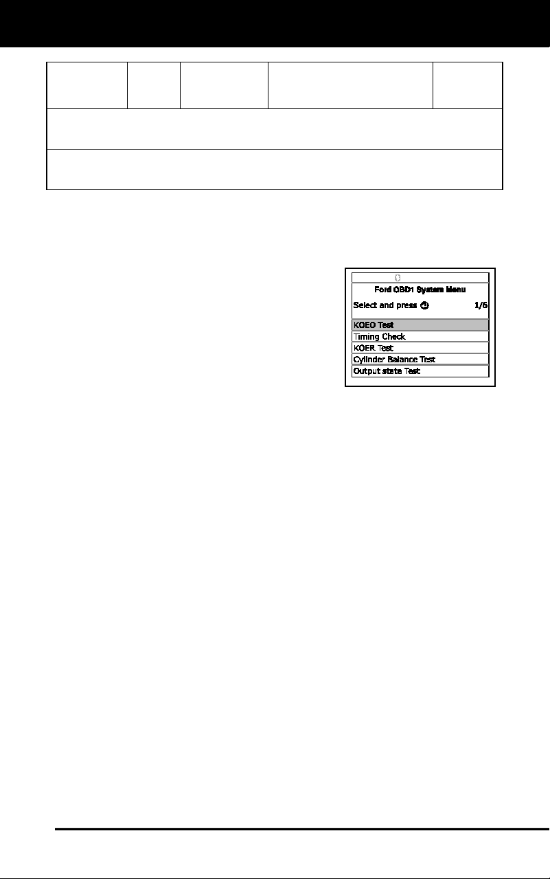
Ford OBD1 Systems
CODE RETRIEVAL PROCEDURES - KOEO TEST
45
Engine
8th
VIN
Digit**
Fuel Systems
(Carburetor
Model)
Application/Special Notes
Computer
System
**VIN Number. The VIN number(s) used in this column identify the vehicle’s engine type.
This number is the 8th digit of the VIN (Vehicle Identification Number). Consult your vehicle’s
repair manual for details.
Application Table Definitions. EFI = Electronic Fuel Injection; FBC = Feedback Carburetor;
MFI = Multiport Fuel Injection; OHC = Overhead Cam; SC = Super Charged; SEFI =
Sequential Electronic Fuel Injection; SFI = Sequential Fuel Injection
CODE RETRIEVAL PROCEDURES
Overview of Ford Code Retrieval Process
Ford's computer self-diagnostic system is
divided into four main sections:
1. "Key On Engine Off" (KOEO) Self-Test
2. "Continuous Memory" (CM) Self-Test
3. "Key On Engine Running" (KOER) Self-
Test
4. Other EEC-IV System tests
These Self-Tests are specially designed to monitor and/or test the
various components and circuits that are controlled by the vehicle's
computer, and to save and/or transmit diagnostic test results to the
Scan Tool in the form of numerical fault codes.
The "Continuous Memory" Self-Test is designed to run continuously
whenever the vehicle is normal operation. If a fault is detected by the
"Continuous Memory" Self-Test, a fault code is saved in the vehicle's
computer memory for later retrieval.
Ford’s On-Board Diagnostic Self-Tests are designed in such a way that
in order to properly diagnose a problem, you must perform all the Self-
Tests, in the proper sequence.
As described previously, some tests are designed to detect problems
only when the vehicle is in normal operation. Some tests are designed
to activate components and detect problems only with the Key On and
Engine Off. Other tests are designed to activate components and test
their operation only with the Key On and Engine Running. Do not take
short cuts. If you fail to perform a test, or you perform a test out of
sequence, you might miss a problem that is only detected during that
part of the test.
Key On Engine Off (KOEO) Test
During the KOEO Self-Test, two groups of codes are retrieved
The first group of codes are called "KOEO codes". A "KOEO" icon
shows to indicate the code is a "KOEO" code.
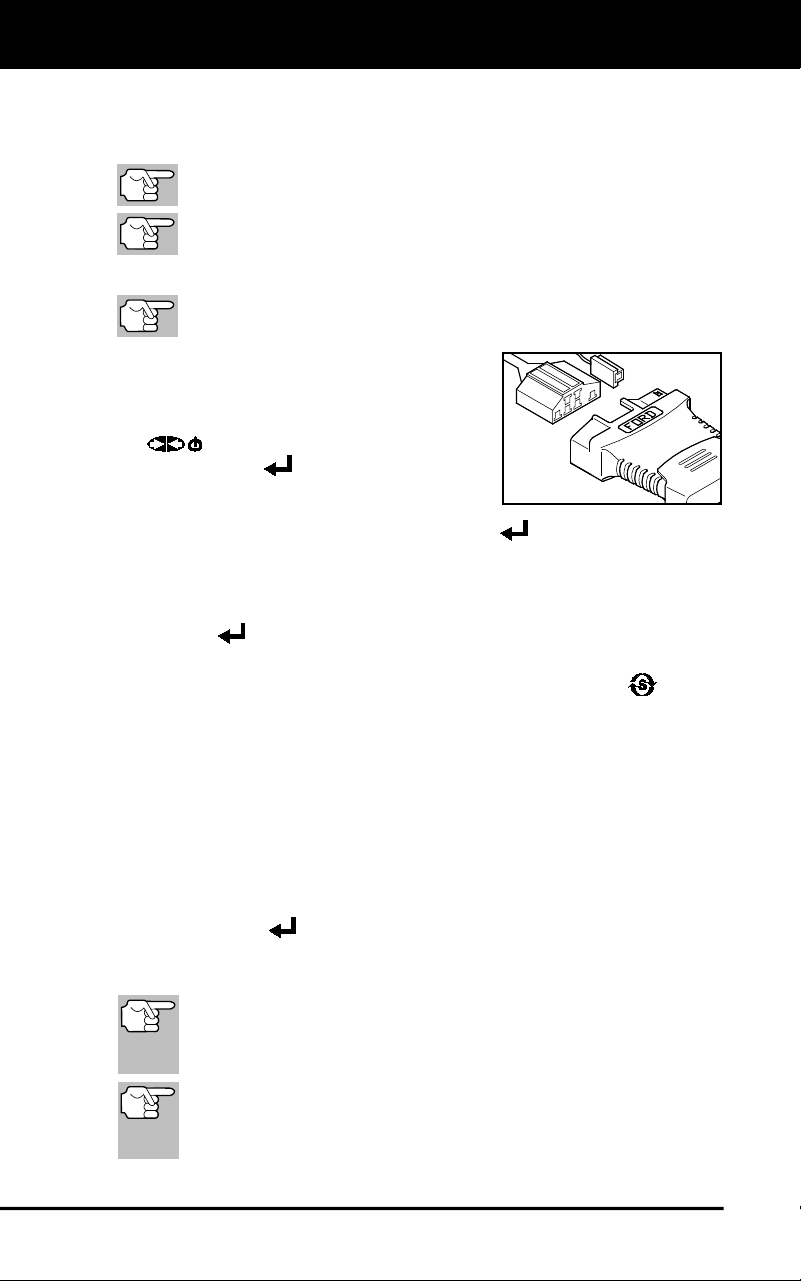
Ford OBD1 Systems
CODE RETRIEVAL PROCEDURES - KOEO TEST
46
The second group of codes are called "Continuous Memory" codes.
A "Continuous Memory" icon shows to indicate the code is a
"Continuous Memory" code.
Check your vehicle thoroughly before performing any test.
ALWAYS observe safety precautions whenever working on a
vehicle.
1. Locate the vehicle's Data Link Connector (DLC).
Some DLCs have a plastic cover that must be removed before
connecting the Scan Tool.
2. Connect the Scan Tool (with the Ford
Connector Cable Adaptor attached) to the
vehicle's DLC. Connect the Scan Tool to
BOTH connectors. Press POWER/LINK
to turn the Scan Tool ON, then
press ENTER
to continue.
The Ford Menu displays.
3. Highlight KOEO Test, then press ENTER
.
The LCD display shows instructions to prepare the vehicle for the
KOEO Test.
4. Start and warm the engine to normal operating temperature. Press
ENTER
to continue.
5. Turn ignition key OFF and wait for the on screen prompt. If you wish
to exit the KOEO test at this time, press SYSTEM MENU
.
6. Turn the ignition ON. DO NOT start the engine. If your vehicle is
equipped with one of the following engine types, perform the added
procedures described below:
For 4.9L engines with standard transmission: Press and hold
the clutch until all codes are sent (steps 7 through 9).
For 7.3L diesel engines: Press and hold accelerator until all
codes are sent (steps 7 through 9).
For 2L turbo engines with octane switch: Put switch in
premium position.
7. Press ENTER
to continue.
8. A “One moment please KOEO test is in progress…” message
shows while codes are being retrieved.
When the ignition is turned "on", the vehicle's computer enters
the Self-Test mode. Clicking sounds will be heard. This
indicates that the vehicle's computer is activating relays,
solenoids, and other components to check their operation.
WARNING: On some vehicles equipped with an Electric
Cooling Fan, the computer activates the cooling fan to check
its operation. To avoid injury, keep hands or any part of your
body a safe distance from the engine during this test.
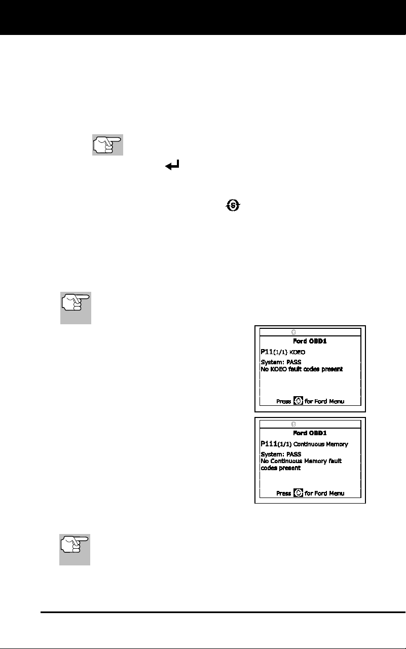
Ford OBD1 Systems
CODE RETRIEVAL PROCEDURES - KOEO TEST
47
If the Scan Tool fails to link to the vehicle's computer, a "Vehicle is
not responding" message shows.
- Verify the ignition is ON.
- Check the cable connections at the Scan Tool and at the
vehicle's DLC.
- Turn the ignition OFF, wait 10 seconds, then turn back ON to
reset the computer.
BE SURE to perform the added procedures in step 6, if
appropriate, BEFORE turning the ignition ON.
- Press ENTER
to continue.
If the Scan Tool cannot link to the vehicle’s computer after three
attempts, the message “Contact Technical Support” displays.
- Press the SYSTEM MENU
button to return to the Ford
Menu.
- Turn the ignition off, and disconnect the Scan Tool.
- Contact Technical Support for assistance.
9. If the Scan Tool was able to link to the vehicle successfully a "Code
retrieval was successful..." message shows temporarily, followed by
any retrieved DTCs.
Most Ford EEC-IV vehicle computers up to 1991 use a two-digit
code system. From 1991 to 1995 most use a three digit code
system.
The Scan Tool will display a code
only if codes are present in the
vehicle's computer memory.
If no problems are found during the
KOEO Self-Test, the computer
sends a "PASS" code (code 11 or
111) to the Scan Tool.
If no Continuous Memory codes are
present in the vehicle's computer me-
mory, the Scan Tool displays a
"PASS" code (code 11 or 111).
The Scan Tool will display a code only
if codes are present. If no codes are
present, the message “No DTCs are
presently stored in the vehicle’s
computer” displays.
10. If more than one code was retrieved, press DTC/FF, as necessary,
to display additional codes one at a time.
In the case of long code definitions, a small arrow is shown in
the upper/lower right-hand corner of the code display area to
indicate the presence of additional information.
11. Disconnect the Scan Tool from the vehicle and turn the ignition key
OFF.
Ford OBD1 Systems
CODE RETRIEVAL PROCEDURES - ENGINE TIMING CHECK
48
12. To prolong battery life, the Scan Tool automatically shuts "Off" after
approximately three minutes of no button activity. The DTCs retrieved
will remain in the Scan Tool's memory, and may be viewed at any time.
If the Scan Tool's batteries are removed, or if the Scan Tool is re-linked
to a vehicle to retrieve codes, any prior codes in its memory are
automatically cleared.
13. Follow the testing and repair procedures outlined in the vehicle's
service repair manual to correct "hard" DTCs. Codes should be
addressed and eliminated in the order they were received, erasing
and retesting after each repair is done to be sure the fault was
eliminated.
IMPORTANT: Before "Continuous Memory" codes can be
serviced, both the KOEO and the KOER Self-Tests must pass
(a PASS code 11 or 111 is obtained). After both of these tests
have passed, erase the vehicle's computer memory, take the
vehicle for a short drive, then repeat the KOEO Self-Test. If
any Continuous Memory faults are present, service them all
this time.
Do not proceed to the ignition timing check procedure or the
KOER test until a PASS code (code 11 or 111) for KOEO test
is obtained.
Engine Timing Check
Before performing the KOER Self-Test, the vehicle's Ignition
Base Timing and the computer's ability to electronically control
timing advance must be checked for proper operation.
This procedure is only applicable to 1992 and older
vehicles (excluding diesel engines). For 1993 and newer
vehicles, refer to the vehicle's service repair manual for
procedures to check and adjust timing.
For 1992 and older vehicles, the Scan Tool can be used in combination
with a timing light to check ignition timing and the vehicle computers
ability to advance ignition timing.
Check your vehicle thoroughly before performing any test.
ALWAYS observe safety precautions whenever working on a
vehicle.
A timing light is required to perform this test.
The vehicle must pass the KOEO Test (page 45) before performing
this test.
1. Locate the vehicle's Data Link Connector (DLC).
Some DLCs have a plastic cover that must be removed before
connecting the Scan Tool's cable connector.
2. Connect the Scan Tool (with the Ford Connector Cable Adaptor
attached) to the vehicle's DLC. Connect the Scan Tool to BOTH
connectors. Press POWER/LINK
to turn the Scan Tool ON,
then press ENTER
to continue.
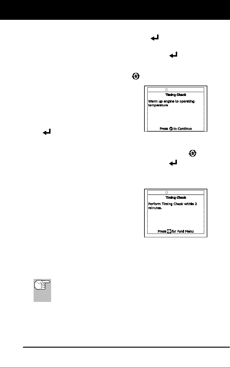
Ford OBD1 Systems
CODE RETRIEVAL PROCEDURES - ENGINE TIMING CHECK
49
The Ford Menu displays.
3. Highlight Timing Check, then press ENTER
.
The Select Model Year screen displays.
4. Highlight the vehicle model year, then press ENTER
.
For 1993 and newer vehicles: The message “Follow
instructions in vehicle service manual to perform timing check”
displays. Press SYSTEM MENU
to return to the Ford Menu.
Refer to the vehicle’s service
manual for procedures.
For 1992 and older vehicles: The
message “Warm up engine to
operating temperature” displays.
5. Start and warm the engine to normal
operating temperature. Press ENTER
to continue.
6. When prompted, turn off all vehicle accessories, turn ignition key
OFF and wait for the on screen prompt. If you wish to exit the
Timing Check procedure at this time, press SYSTEM MENU
.
7. When instructed, start the engine and press ENTER
.
A "One moment please preparation for test is in progress”
message shows temporarily, followed by the message "Perform
Timing Check within two minutes."
8. Perform the Timing Check as follows:
The vehicle's computer is pro-
grammed to advance ignition timing
20° (±3°) above the vehicle's "base
timing" value, and to freeze this
setting for two minutes from the time
the "Perform Timing Check within 2
minutes" message displays.
Within this two-minute period, follow instructions in the vehicle's
service repair manual to check the ignition timing with a timing
light and ensure that it is 20° above the specified base timing
value (±3°).
Example: If base timing specification is 10° BTDC, the acceptable
timing light reading should be in the range of 27° to 33° BTDC.
Base-timing specifications can be found on the Vehicle
Emission Control Information (VECI) decal. If the VECI decal
is missing or damaged, refer to your vehicle's service repair
manual for specifications.
9. If timing light readings are within the acceptable range:
Base timing and the vehicle computer's ability to advance timing
are working properly.
Proceed to the KOER Self-Test.
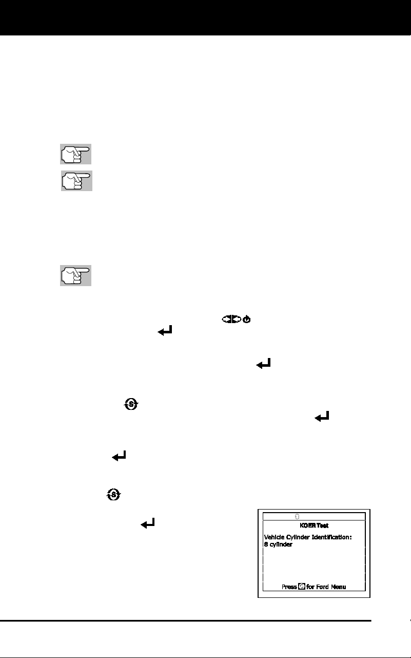
Ford OBD1 Systems
CODE RETRIEVAL PROCEDURES - KOER TEST
50
10. If timing light readings are not within the acceptable range:
Base timing may be out of adjustment, or the computer may
have problems with the timing advance circuit.
Refer to the vehicle's service repair manual for procedures on
adjusting and/or repairing ignition timing. Repairs to ignition
timing must be made before proceeding to the KOER Test.
Key on Engine Running (KOER) Self-Test
Check your vehicle thoroughly before performing any test.
ALWAYS observe safety precautions whenever working on a
vehicle.
The vehicle must pass the KOEO Test (page 45) before performing
this test.
The vehicle must pass the Engine Timing Check (page 48) before
performing this test.
1. Locate the vehicle's Data Link Connector (DLC).
Some DLCs have a plastic cover that must be removed before
connecting the Scan Tool cable connector.
2. Connect the Scan Tool (with the Ford Connector Cable Adaptor
attached) to the vehicle's DLC. Connect the Scan Tool to BOTH
connectors. Press POWER/LINK
to turn the Scan Tool ON,
then press ENTER
to continue.
The Ford Menu displays.
3. Highlight KOER Test, then press ENTER
.
The message “Make sure ignition timing is within factory
specifications” displays. If necessary, press press SYSTEM
MENU
to return to the Ford Menu, and perform an Engine
Timing Check (page 48). Otherwise, press ENTER
button to.
4. The message “Warm up engine to operating temperature” displays.
Start and warm the engine to normal operating temperature. Press
ENTER
to continue.
5. When prompted, turn off all vehicle accessories, turn ignition key
OFF. If you wish to exit the KOER test at this time, press SYSTEM
MENU
.
6. When instructed, start the engine and
press ENTER
to continue. A "One
moment please KOER test is in
progress..." message shows temporarily.
7. The Scan Tool retrieves the Cylinder
Identification (ID) Code. identifies the
number of cylinders for the vehicle
under test).
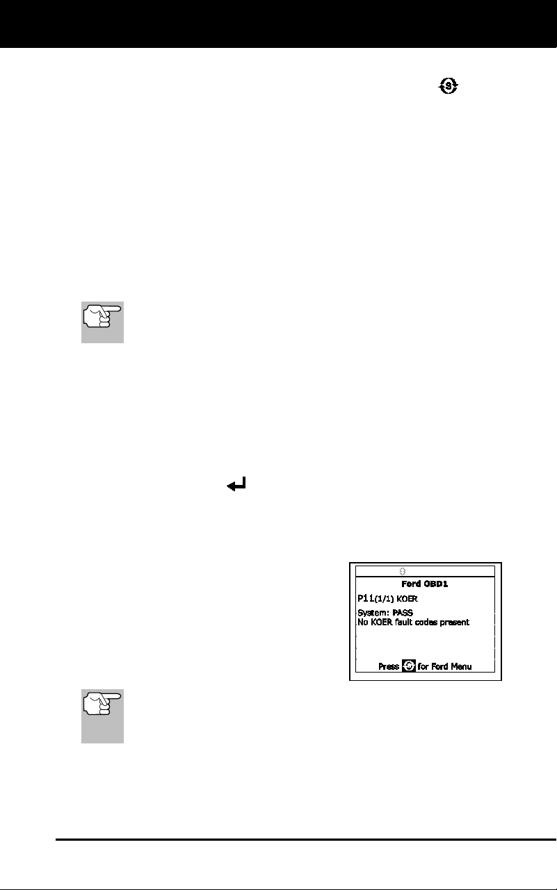
Ford OBD1 Systems
CODE RETRIEVAL PROCEDURES - KOER TEST
51
If the Scan Tool cannot retrieve the Cylinder ID Code, an
advisory message displays. Press SYSTEM MENU
to exit
and repeat the Key On Engine Off (KOEO) test (page 45) until
DTC 11 or 111 displays.
8. Perform the following procedures when prompted.
Turn the steering wheel 1/2 turn to right, hold for four seconds
and release.
Press the brake pedal to the floor and then release it.
Cycle the Overdrive Switch (if equipped).
Quickly press the accelerator pedal to the floor and then release it.
9. After the above procedures are performed a "One moment please
KOER test is in progress..." message shows temporarily, followed by a
"Retrieving codes" message.
Most Ford EEC-IV vehicle computers up to 1991 use a two-digit
code system. From 1991 to 1995 most use a three-digit code
system.
If the Scan Tool fails to link to the vehicle’s computer, a “Vehicle
is not responding” message shows.
- Verify the ignition is ON.
- Check the cable connections at the Scan Tool and at the
vehicle’s DLC.
- Turn the ignition OFF, wait 10 seconds, then turn back ON to
reset the computer.
- Press ENTER
to continue.
The Scan Tool will display a code only if codes are present in
the vehicle’s computer memory. If no codes are present, a “No
DTC’s are presently stored in the vehicle’s computer” message
is displayed.
10. If no problems are found during the
KOER Self-Test, the computer sends a
"PASS code" (code 11 or 111) to the
Scan Tool.
11. After the Scan Tool retrieves all the
KOER Self-Test DTCs, turn the engine
off, and disconnect the Scan Tool from
the vehicle's test connectors.
All retrieved DTCs will remain in the Scan Tool's memory. If
the KOER Test procedure is performed again, DTC's from a
prior test will automatically clear and will be replaced by the
most current DTCs retrieved.
12. All KOER codes that are retrieved by the Scan Tool during the
KOER Self-Test represent problems that are present now (at the
time the test is performed). The related vehicle problems that
caused the codes to be sent must be repaired using the procedures
described in the vehicle's repair manual.
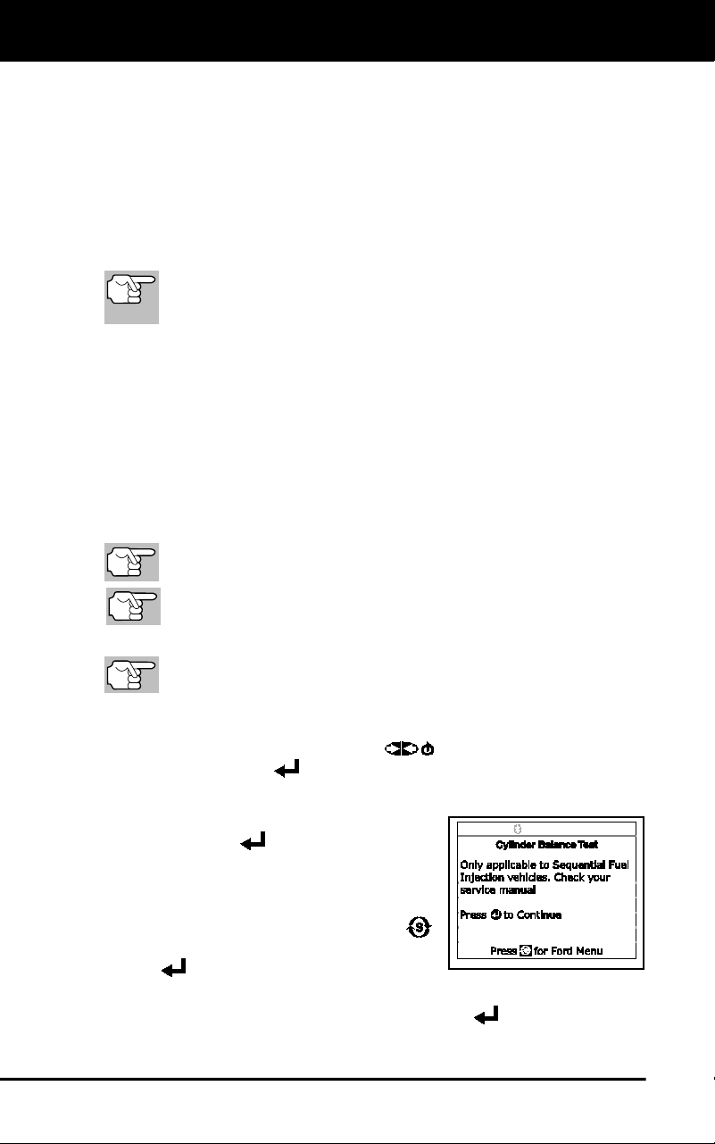
Ford OBD1 Systems
ADDITIONAL TESTS FOR EEC-IV SYSTEMS - CYLINDER BALANCE TEST
52
13. After all repairs have been completed, repeat the KOER Self-Test.
14. If a "pass code" (code 11 or 111) is received, it indicates that the
repairs were successful and all the related systems are working
properly.
15. If a "pass code" (code 111 or 111) is not received, the repair was
unsuccessful. Consult the vehicle's service manual and recheck
repair procedure.
ADDITIONAL TESTS FOR EEC-IV SYSTEMS
These tests are additional, supplemental tests, and are not
needed to retrieve Diagnostic Trouble Codes. They are
included to further assist in troubleshooting vehicle problems.
Cylinder Balance Test (Vehicles equipped with Sequential
Electronic Fuel Injected (SEFI) systems only)
The Cylinder Balance Test assists in finding a weak or noncontributing
cylinder. The computer shuts off fuel (cuts off power to injectors) to each
cylinder, in sequence, and monitors for RPM changes (drop). Based on
this information, the computer determines if all the cylinders are
contributing power equally (for proper engine operation), or if some
cylinders are only contributing partially or not contributing at all.
Cylinder Balance Test Procedure
Check your vehicle thoroughly before performing any test.
ALWAYS observe safety precautions whenever working on a
vehicle.
1. Locate the vehicle's Data Link Connector (DLC).
Some DLCs have a plastic cover that must be removed before
connecting the Scan Tool cable connector.
2. Connect the Scan Tool (with the Ford Connector Cable Adaptor
attached) to the vehicle's DLC. Connect the Scan Tool to BOTH
connectors. Press POWER/LINK
to turn the Scan Tool ON,
then press ENTER
to continue.
The Ford Menu displays.
3. Highlight Cylinder Balance Test, then
press ENTER
.
An advisory message displays. If
the vehicle is not equipped with
Sequential Electronic Fuel Injection
(SEFI), press SYSTEM MENU
to exit. Otherwise, press ENTER
to continue.
4. An “instructional” message displays. Start and warm the engine to
normal operating temperature. Press ENTER
to continue.
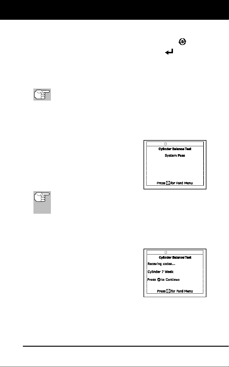
Ford OBD1 Systems
ADDITIONAL TESTS FOR EEC-IV SYSTEMS – RELAY AND SOLENOID TEST
53
5. When prompted, turn off all vehicle accessories, turn ignition key
OFF and wait for the on screen prompt. If you wish to exit the
Cylinder Balance test at this time, press SYSTEM MENU
.
6. When instructed, start the engine and press ENTER
.
A "One moment please preparation for test is in progress..."
message shows temporarily.
7. When prompted, lightly press the accelerator pedal half way and
release to activate the cylinder balance test.
For 1986 models ONLY: Fully press accelerator once and
release.
The computer is now in Cylinder Balance Test mode, and will start
cutting fuel to each cylinder in sequence to determine if all the
cylinders are contributing equally. It may take up to five minutes
before the test results are transmitted to the Scan Tool.
8. If the vehicle's computer fails to enter Cylinder Balance Test mode,
do the following:
Lightly press the accelerator pedal
again as described in step.
9. After the Cylinder Balance Test is
completed, the test results are sent to
the Scan Tool.
10. If all cylinders are contributing equally, a
“System Pass” message will display.
If the computer detects a problem with a cylinder(s) when
performing the initial Cylinder Balance Test, it needs to repeat the
test two more times to properly determine which cylinder or cylin-
ders are malfunctioning.
11. If a cylinder is not contributing at the same level as the other
cylinders, the computer prompts you to repeat the test two more
times by displaying the “Lightly press the accelerator half way and
release” message again. Each time the message displays, perform
the procedures as instructed.
12. After the Cylinder Balance tests have
completed, the computer will identify and
display which cylinder (or cylinders) are
not contributing equally.
If any weak cylinders are identified,
consult the vehicle’s service repair
manual to perform further testing
and/or repairs.
Relay and Solenoid Test (Output State Check)
The "Output State Check" lets you energize (turn ON) and de-energize
(turn OFF), on command, most of the actuators (relays and solenoids)
that are controlled by the vehicle’s computer.
Use this test to check computer output voltages and relay/solenoid
operation.
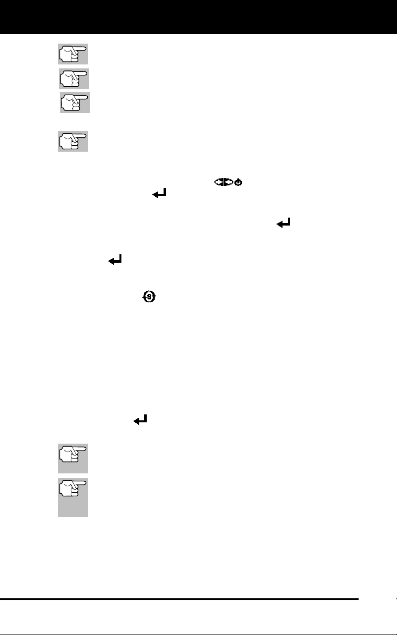
Ford OBD1 Systems
ADDITIONAL TESTS FOR EEC-IV SYSTEMS - RELAY AND SOLENOID TEST
54
The fuel injectors and fuel pump are not energized during this
test.
Check your vehicle thoroughly before performing any test.
ALWAYS observe safety precautions whenever working on a
vehicle.
1. Locate the vehicle's Data Link Connector (DLC).
Some DLCS have a plastic cover that must be removed before
connecting the Scan Tool cable connector.
2. Connect the Scan Tool (with the Ford Connector Cable Adaptor
attached) to the vehicle's DLC. Connect the Scan Tool to BOTH
connectors. Press POWER/LINK
to turn the Scan Tool ON,
then press ENTER
to continue.
The Ford Menu displays.
3. Highlight Output State Test, then press ENTER
.
4. The message “Warm up engine to operating temperature” displays.
Start and warm the engine to normal operating temperature. Press
ENTER
to continue.
5. When prompted, turn ignition key OFF and wait for the on screen
prompt. If you wish to exit the Output State Check at this time, press
SYSTEM MENU
.
6. When prompted, turn ignition ON. DO NOT start the engine. If your
vehicle is equipped with one of the following engine types, perform
the added procedures described below:
For 4.9L engines with standard transmission: Press and hold
the clutch until the "Output State Check Active" screen displays.
For 7.3L diesel engines: Press and hold accelerator until the
"Output State Check Active" screen displays.
For 2L turbo engines with octane switch: Put switch in
premium position.
7. Press ENTER
to continue.
8. A "One moment please test is in progress..." message shows.
When the ignition is turned "on", the vehicle's computer enters
the Self-Test mode. Clicking sounds will be heard. This is
normal.
WARNING: On some vehicles equipped with an Electric
Cooling Fan, the computer activates the cooling fan to
check its operation. To avoid injury, keep hands or any part
of your body a safe distance from engine during the test.
If the Scan Tool fails to link to the vehicle's computer, a “Vehicle is
not responding” message shows.
- Verify the ignition is ON.
- Check the cable connections at the Scan Tool and at the
vehicle’s DLC.
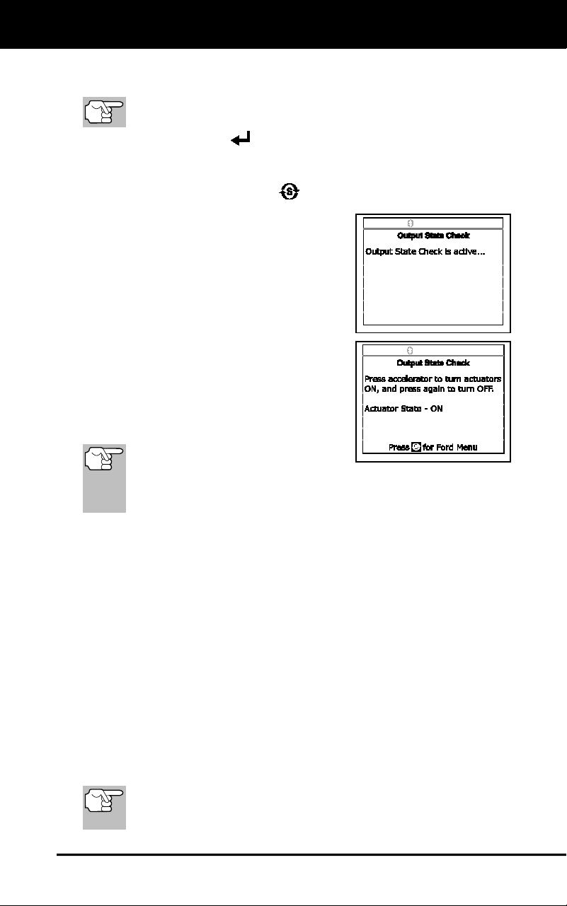
Ford OBD1 Systems
ADDITIONAL TESTS FOR EEC-IV SYSTEMS - WIGGLE TEST
55
- Turn the ignition OFF, wait 10 seconds, then turn back ON to
reset the computer.
BE SURE to perform the added procedures in step 6, if
appropriate, BEFORE turning the ignition ON.
- Press ENTER
to continue.
If the Scan Tool cannot link to the vehicle's computer after three
attempts, the message “Contact Technical Support” displays.
- Press SYSTEM MENU
to return to the Ford Menu.
- Turn the ignition OFF, and
disconnect the Scan Tool.
- Contact Technical Support for
assistance.
9. If the Scan Tool was able to link to the
vehicle successfully an "Output State
check active..." message shows temporar-
ily, followed by a display that instructs you
how to perform the test.
10. When prompted, press the accelerator
pedal once, then release. This activates
the Output State Check and energizes
most of the actuators (relays and
solenoids) that are controlled by the
vehicle's computer.
If your vehicle is equipped with an
Integrated Vehicle Speed Control,
disconnect the vacuum supply hose from the speed control
servo before pressing the accelerator. Reconnect vacuum
hose after test.
11. To de-energize the actuators, press the accelerator pedal again and
release.
12. The procedure can be repeated as many times as desired by
pressing and releasing the accelerator pedal.
13. Consult the vehicle's service repair manual for a list of actuators
(solenoids and relays) controlled by the computer that apply to the
vehicle under test, and which actuators should energize and de-
energize when performing the Output State Check. All applicable
actuators should be on when energized and off when de-energized.
14. If an actuator is not responding to the Output State Check, follow the
procedures described in the vehicle's service manual to check
computer actuator output circuit voltages and/or grounds.
15. To quit the Output State Check, turn the ignition OFF and
disconnect the Scan Tool from the vehicle.
Wiggle Test
Since any DTC’s from Wiggle Test results are saved in
Continuous Memory, it is suggested that you clear any DTC’s
in Continuous Memory before performing Wiggle Test.
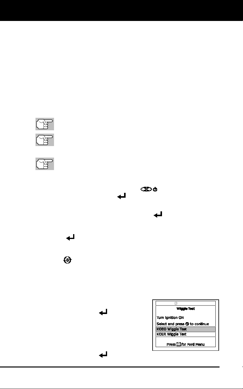
Ford OBD1 Systems
ADDITIONAL TESTS FOR EEC-IV SYSTEMS - WIGGLE TEST
56
Use this test to check for intermittent faults in some circuits.
Circuits Tested:
1984 & Newer - Air Charge Temp Sensor (ACT), Barometer Pressure
Sensor (BP), Engine Coolant Temp Sensor (ECT), Exhaust Gas
Oxygen Sensor (EGO), EGR Valve Position Sensor (EVP), Manifold
Absolute Pressure (MAP), Throttle Position Sensor (TP), Vane Air Temp
Sensor (VAT)
1985 & Newer - Vane Air Flow Sensor (VAF)
1986 & Newer - Pressure Feedback EGR Sensor (PFE)
1990 & Newer - Exhaust Gas Oxygen Sensor (EGO), Ignition
Diagnostic Monitor (IDM) (DIS or Dual Plug DIS only), Idle Tracking
Switch (ITS), Mass Air Flow Sensor (MAF)
Check your vehicle thoroughly before performing any test.
ALWAYS observe safety precautions whenever working on a
vehicle.
1. Locate the vehicle's Data Link Connector (DLC).
Some DLCs have a plastic cover that must be removed before
connecting the Scan Tool cable connector.
2. Connect the Scan Tool (with the Ford Connector Cable Adaptor
attached) to the vehicle's DLC. Connect the Scan Tool to BOTH
connectors. Press the POWER/LINK
button to turn the Scan
Tool ON, then press ENTER
to continue.
The Ford Menu displays.
3. Highlight Wiggle Test, then press ENTER
.
4. The message “Warm up engine to operating temperature” displays.
Start and warm the engine to normal operating temperature. Press
ENTER
to continue.
5. When prompted, turn ignition key OFF and wait for the on screen
prompt. If you wish to exit the KOEO test at this time, press SYSTEM
MENU
.
6. Select the desired Wiggle Test from the menu displayed.
To perform the KOEO Wiggle Test:
- Highlight KOEO Wiggle Test.
- Turn ignition ON. DO NOT
START THE ENGINE.
- Press ENTER
to continue.
To perform the KOER Wiggle Test:
- Highlight KOER Wiggle Test.
- Turn the ignition ON and start the
engine.
- Press ENTER
to continue.
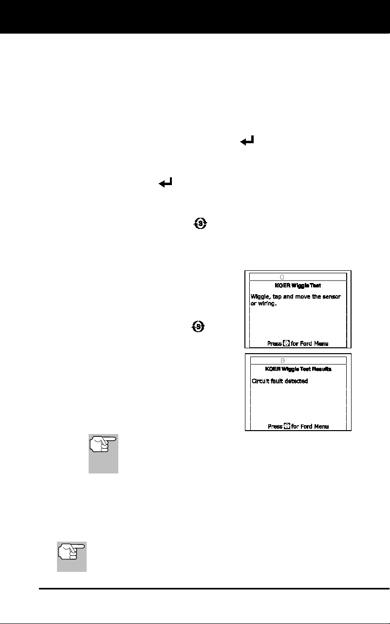
Ford OBD1 Systems
ERASING DTCs
57
7. A "One moment please test is in progress" message shows
temporarily.
If the Scan Tool fails to link to the vehicle's computer, a "Vehicle is
not responding" message shows.
For KOEO Wiggle Test:
- Verify the ignition is ON.
- Turn the ignition OFF, wait 10 seconds, then turn back ON to
reset the computer. Press ENTER
to continue.
For KOER Wiggle Test:
- Turn the engine OFF, wait 10 seconds, then turn back ON.
Press ENTER
to continue.
If the Scan Tool cannot link to the vehicle’s computer after three
attempts, the message “Contact Technical Support” displays.
- Press SYSTEM MENU
to return to the Ford Menu.
- Turn the ignition OFF, and disconnect the Scan Tool.
- Contact Technical Support for assistance.
8. If the Scan Tool was able to link to the
vehicle successfully, a "Wiggle test is
active..." message shows temporarily,
followed by a message instructing you
how to perform the test.
Press SYSTEM MENU if you
wish to exit the Wiggle Test at this
time.
9. Wiggle, tap and move the suspected
sensor or wiring.
If no faults are detected, a "System
Pass" message displays.
If a fault is detected, a "Circuit Fault
detected" message displays.
If the Wiggle Test detects any problems, the related
DTC will be stored by the computer in "Continuous
Memory". To view any Wiggle Test DTC’s you must
perform the KOEO Test (see page 45).
10. Follow the procedures in the vehicle's service repair manual to
perform troubleshooting and repairs for Wiggle Test results.
11. The Wiggle Test will stay active as long as desired. To quit the
Wiggle Test, turn the ignition OFF and disconnect the Scan Tool.
ERASING DTCs
When the Scan Tool's ERASE function is used to erase DTCs
from the vehicle's on-board computer, manufacturer specific
data (where applicable) is also erased.
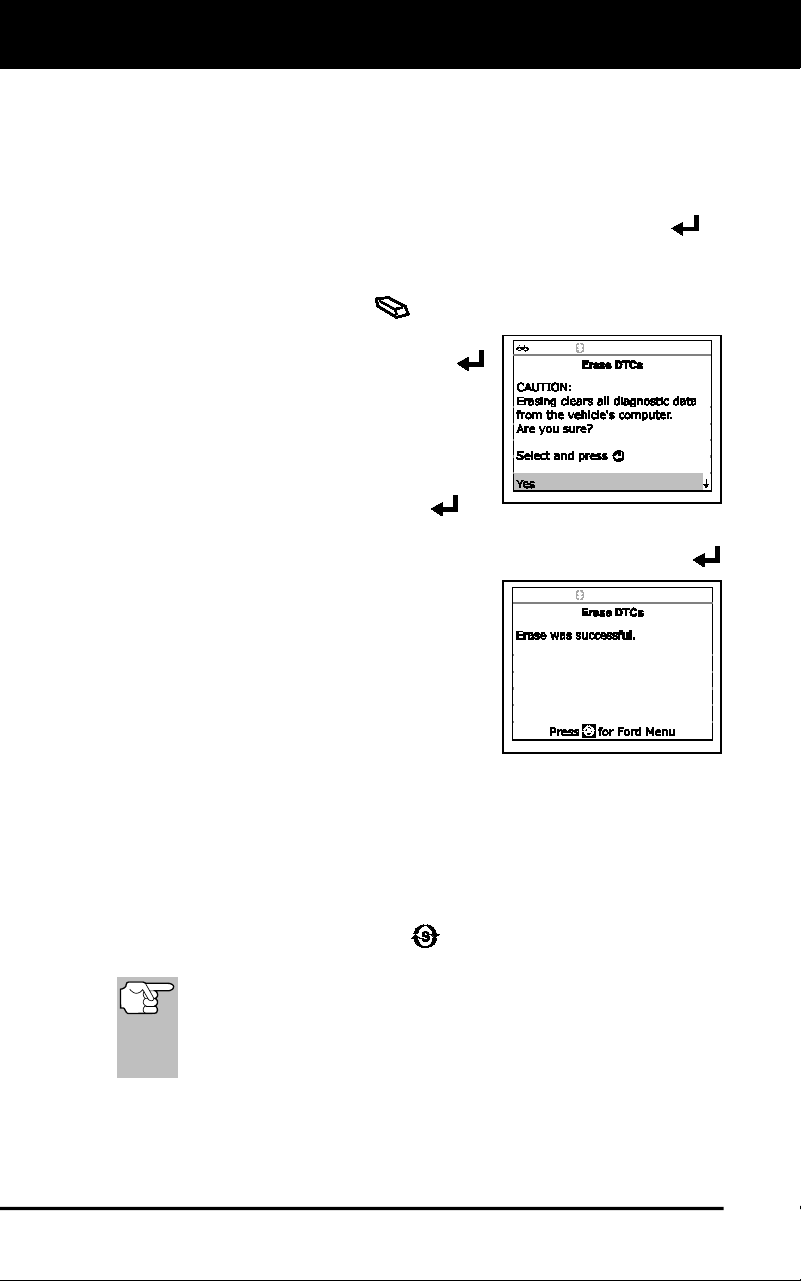
Ford OBD1 Systems
ERASING DTCs
58
If you plan to take the vehicle to a service center for repair, DO NOT
erase the codes from the vehicle's computer. If the codes are erased,
valuable information that might help the technician troubleshoot the
problem will also be erased.
Erase DTC’s from the computer’s memory as follows:
1. Connect the Scan Tool to the vehicle’s DLC. Press ENTER to
continue.
2. Turn the ignition ON. DO NOT start the engine.
3. Press and release ERASE
. A confirmation message shows.
If you are sure you want to proceed,
select YES, then press ENTER
to continue. An “instructional”
message displays.
- Turn the ignition OFF and wait
for the on-screen prompt.
- When prompted, turn the ignition
ON and press ENTER
to
continue.
If you do not want to proceed, select NO, then press ENTER
to exit the erase function.
4. If you chose to erase DTCs, a “One
moment please…” message displays
while the erase function is in progress.
If the erase was successful, a confir-
mation message shows. The Scan
Tool automatically re-links to the
vehicle’s computer after three seconds.
If the erase was not successful, an “advisory” message shows.
- Verify the ignition is ON.
- Check the cable connections at the Scan Tool and at the
vehicle’s DLC.
- Turn the ignition OFF, wait 10 seconds, then turn back ON to
reset the computer.
- Press SYSTEM MENU
to return to the Ford Menu, then
repeat steps 3 and 4.
Erasing DTCs does not fix the problem(s) that caused the
code(s) to be set. If proper repairs to correct the problem that
caused the code(s) to be set are not made, the code(s) will
appear again and the check engine light will illuminate as soon
as the problem that cause the DTC to set manifests itself.
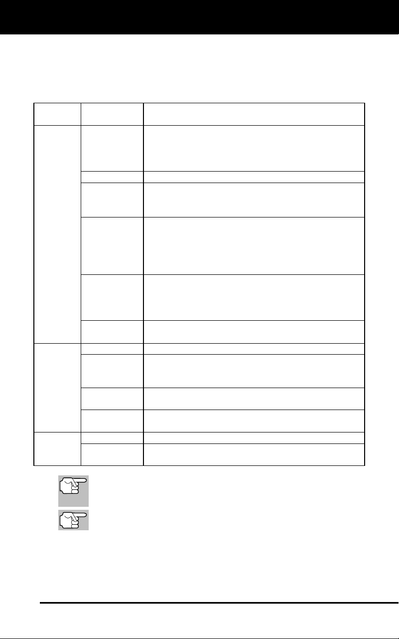
GM OBD1 Systems
YOUR VEHICLE’S COMPUTER SYSTEM - VEHICLES COVERED
59
VEHICLES COVERED
This Scan Tool may be used to retrieve engine service codes from most
General Motors (GM) domestic cars and trucks (EXCEPT Geo, Nova,
Saturn and Sprint).
Model
Year
Make
Model
1982-93
Buick
Century, Electra, Electra Wagon, Estate Wagon,
Le Sabre, Le Sabre Wagon, Park Avenue, Reatta,
Regal, Grand National, Riviera, Roadmaster,
Skyhawk, Skylark, Somerset
Cadillac
De Ville, El Dorado, Fleetwood, Seville
Chevrolet
Beretta, Camaro, Caprice, Cavalier, Celebrity,
Chevette, Citation, Corsica, Corvette, El Camino,
Impala, Lumina, Monte Carlo
Oldsmobile
Achieva, Calais, Custom Cruiser, Cutlass Calais,
Ciera, Cutlass Cruiser, Cruiser Wagon, Cutlass
Supreme, Supreme Classic, Delta 88, Eighty-
eight, Firenze, Ninety-eight, Omega, Toronado,
Touring Sedan, Trofeo
Pontiac
6000, 6000 STE, Bonneville, Fiero, Firebird,
Grand Am, Grand Prix, J 2000, Lemans,
J Parisienne, Phoenix, Safari, Safari Wagon,
Sunbird, T 1000
Trucks and
Vans
All one ton capacity or less with gas engines
1994
Buick
Roadmaster 5.7 liter
Chevrolet
Camaro 3.4 liter/5.7 liter, Caprice 5.7 liter,
Caprice 5.7 liter, Cavalier 3.1 liter,
Lumina 3.1 liter
Pontiac
Firebird 3.4 liter/5.7 liter, Sunbird 2.0 liter/
3.1 liter
Trucks and
Vans
All one ton capacity or less with gas engines
1995
Chevrolet
Caprice 4.3 liter
Trucks and
Vans
All one ton capacity or less with gas engines
(EXCEPT S/T Series vehicles)
In addition to this list, this Scan Tool IS ALSO
COMPATIBLE with OBD1 GM models that are equipped
with "Climate Control Computers".
For 1994 and 1995 vehicles, only the models listed are
compatible with the Scan Tool.
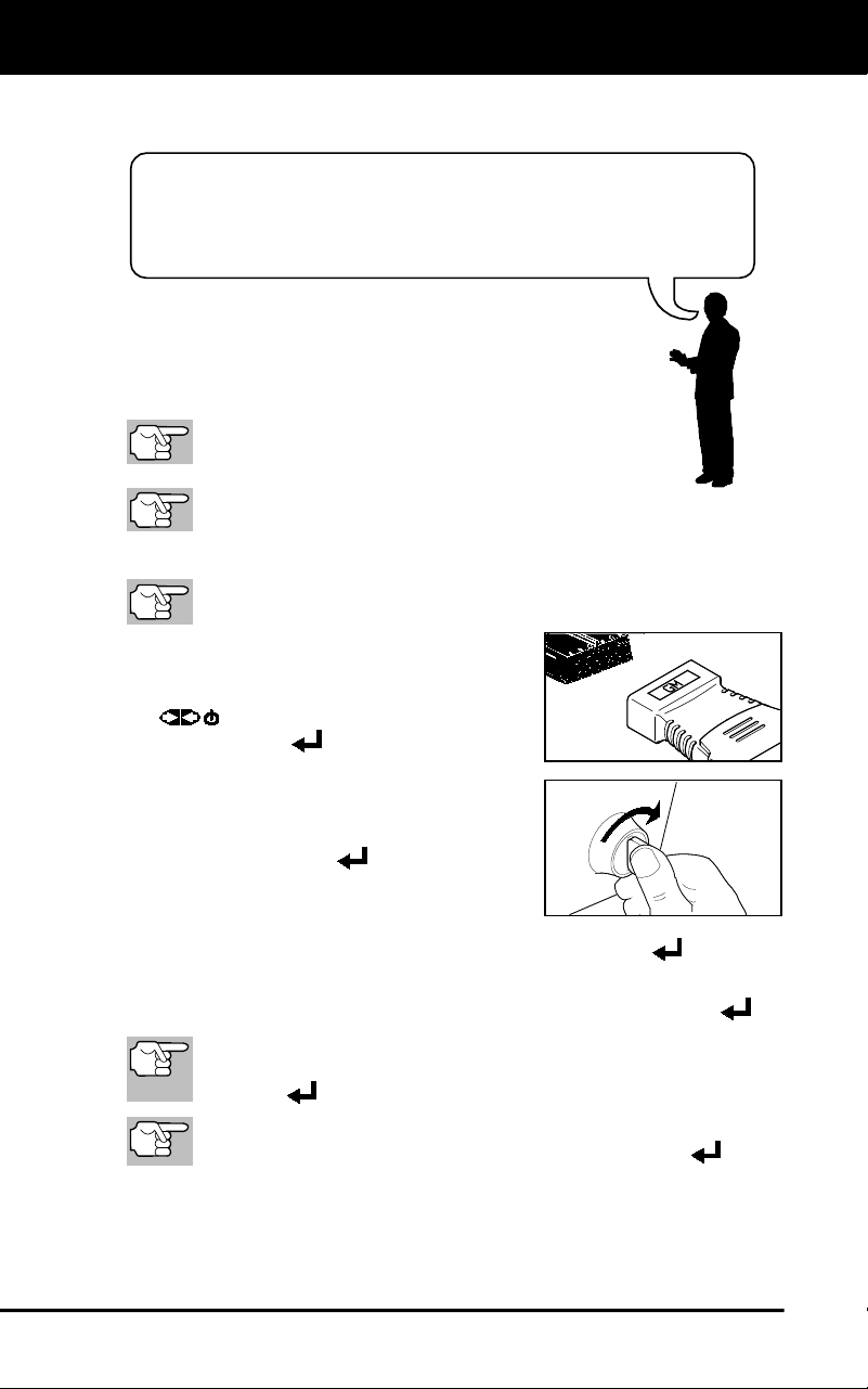
GM OBD1 Systems
CODE RETRIEVAL PROCEDURE
60
Retrieving and using Diagnostic Trouble Codes (DTCs) for
troubleshooting vehicle operation is only one part of an
overall diagnostic strategy.
CODE RETRIEVAL PROCEDURE
Never replace a part based only on the DTC definition.
Each DTC has a set of testing procedures, instructions
and flow charts that must be followed to confirm the
location of the problem. Always refer to the vehicle's
service manual for detailed testing instructions.
Check your vehicle thoroughly before performing
any test.
ALWAYS observe safety precautions whenever working on a
vehicle.
1. Locate the vehicle's Data Link Connector (DLC).
Some DLCs have a plastic cover that must be removed before
connecting the Scan Tool's cable connector.
2. Connect the Scan Tool (with the GM
Connector Cable Adaptor attached) to
the vehicle’s DLC. Press POWER/LINK
to turn the Scan Tool ON, then
press ENTER
to continue.
An “instructional” message shows.
3. Turn the ignition ON. Turn all vehicle
accessories OFF. Select Continue,
then press ENTER
.
The Select Vehicle Year screen
displays.
- Highlight the desired year, then press ENTER
; the Enter
8th VIN menu displays.
4. Highlight the 8th digit of the vehicle’s VIN, then press ENTER
.
If the “Enter 4th VIN Digit” screen displays (not applicable to all
vehicles), highlight the 4th digit of the vehicle’s VIN, then press
ENTER
.
If the “Truck” screen displays (not applicable to all vehicles),
highlight Yes or No, as appropriate, then press ENTER
.
5. When the Scan Tool is in the process of retrieving codes, a "One
moment please..." message shows.
If the Scan Tool fails to link to the vehicle's computer, a "Vehicle
is not responding" message shows.
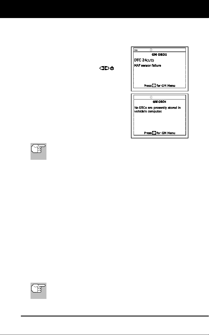
GM OBD1 Systems
CODE RETRIEVAL PROCEDURE
61
- Verify the ignition is ON.
- Check the cable connections at the Scan Tool and at the
vehicle’s DLC.
- Turn the ignition OFF, wait 10-12
seconds, then turn back ON to
reset the computer.
- Press POWER/LINK
.
6. If the Scan Tool was able to link to the
vehicle successfully, the Scan Tool
displays the retrieved DTCs.
The Scan Tool will display a code
only of codes are present in the
vehicle's computer memory. If no
codes are present, a "No DTC's are
presently stored in the vehicle's
computer" message is displayed.
7. If more than one code was retrieved,
press DTC/FF, as necessary, to display
additional codes one at a time.
In the case of long code definitions, a small arrow is shown in the
upper/lower right-hand corner of the code display area to indicate
the presence of additional information.
Code 12 will always be present and it has one of the following meanings:
If code 12 is the only DTC retrieved and your vehicle "STARTS OK"
then code 12 indicates system "PASS" and all computer control
systems are functioning properly.
If code 12 is present and your vehicle "DOES NOT START", then it
may indicate a problem with the ignition control system.
8. Disconnect the Scan Tool from the vehicle and turn the ignition key
OFF.
9. To prolong battery life, the Scan Tool automatically shuts "Off" after
approximately three minutes with no button activity. The DTCs
retrieved will remain in the Scan Tool's memory, and may be viewed
at any time. If the Scan Tool’s batteries are removed, or if the Scan
Tool is re-linked to a vehicle to retrieve codes, any prior codes in its
memory are automatically cleared.
10. Follow the testing and repair procedures outlined in the vehicle's service
repair manual to correct DTCs. Codes should be addressed and
eliminated in the order they were received, erasing and retesting after
each repair is made to be sure the fault was eliminated. Code 12 will
appear alone when no other fault codes are present.
It may be necessary to test drive the vehicle to reset fault codes
13, 15, 24, 44, 45, and 55 after they have been erased.
Whenever codes 51, 52, 54, or 55 are displayed with other
codes, troubleshoot and eliminate the "50 Series" codes first,
then proceed with the lower numbered codes.
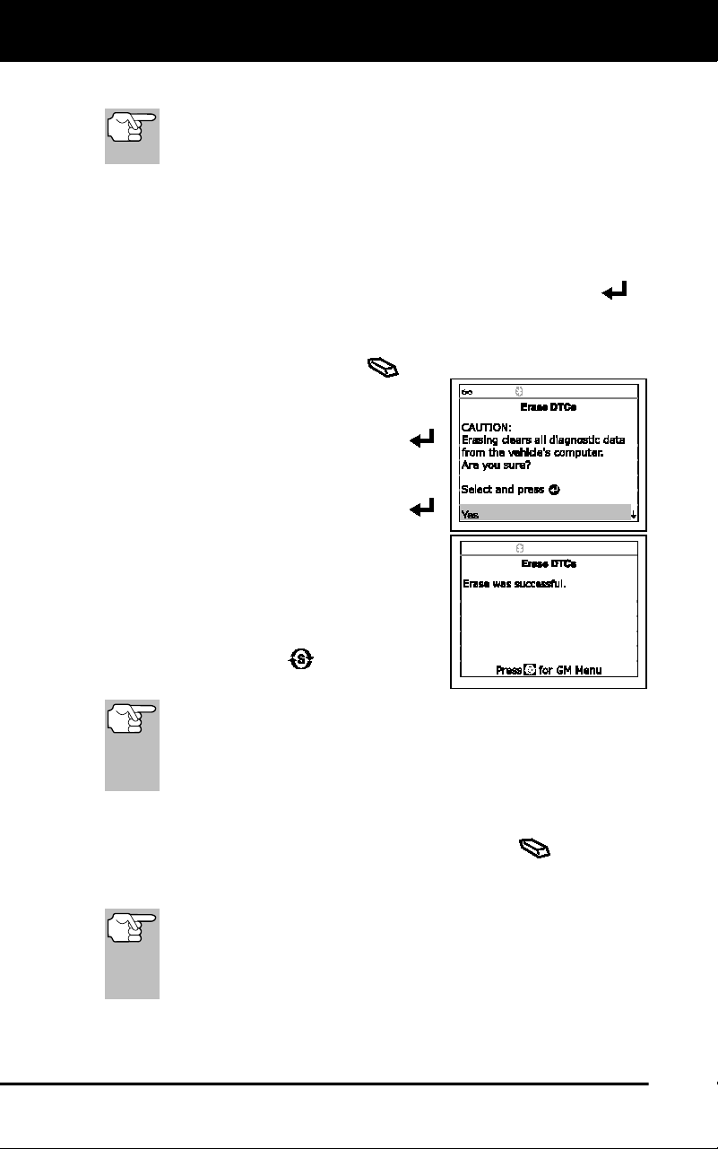
GM OBD1 Systems
ERASING DTCs
62
ERASING DTCs
When the Scan Tool's ERASE function is used to erase DTCs
from the vehicle's on-board computer, manufacturer specific
data (where applicable) is also erased.
If you plan to take the vehicle to a service center for repair, DO NOT
erase the codes from the vehicle's computer. If the codes are erased,
valuable information that might help the technician troubleshoot the
problem will also be erased.
Erase DTC’s from the computer’s memory as follows:
1. Connect the Scan Tool to the vehicle’s DLC. Press ENTER to
continue.
2. Turn the ignition ON. DO NOT start the engine.
3. Press and release ERASE
. A
confirmation message shows.
If you are sure you want to proceed,
select Yes, then press ENTER
to continue.
- If you do not want to proceed,
select No, then press ENTER
to exit the erase function.
4. If you chose to erase DTCs, a “One
moment please…” message displays
while the erase function is in progress.
If the erase was successful, a
confirmation message shows. Press
SYSTEM MENU
to return to the
GM Menu.
The Scan Tool can be used to erase codes for some vehicles,
while others require codes to be erased manually. If the “This
vehicle does not support this function.” screen displays,
consult the vehicle’s service repair manual for procedures to
erase DTCs.
If the erase was not successful, an advisory message shows.
Verify that the Scan Tool is properly connected to the vehicle's
DLC and that the ignition is ON. Press ERASE
to try again.
If the erase process still does not complete, turn the ignition OFF,
wait 10 seconds, then turn back ON and repeat steps 2 and 3.
Erasing DTCs does not fix the problem(s) that caused the
code(s) to be set. If proper repairs to correct the problem that
caused the code(s) to be set are not made, the code(s) will
appear again and the check engine light will illuminate as soon
as the problem that cause the DTC to set manifests itself.
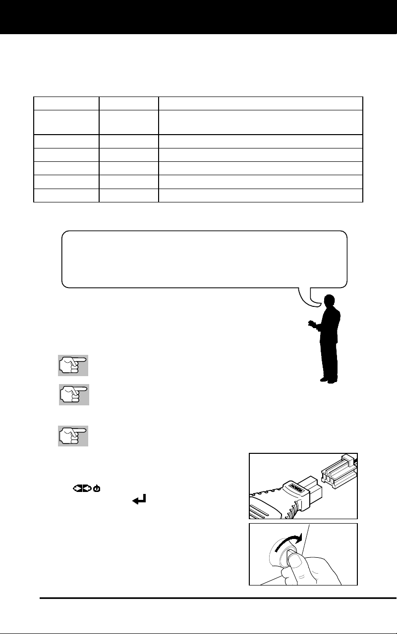
Honda OBD1 Systems
DIAGNOSTIC TROUBLE CODES (DTCs) - CODE RETRIEVAL PROCEDURE
63
Retrieving and using Diagnostic Trouble Codes (DTCs) for
troubleshooting vehicle operation is only one part of an
overall diagnostic strategy.
VEHICLES COVERED
Honda/Acura vehicles use a variety of computer systems. The Scan
Tool may be used to retrieve engine service codes from the following
Honda/Acura vehicles.
Model Year
Make
Model
1990-1991,
1994-1995
Honda
Accord
1992-1995
Honda
Civic
1992-1995
Honda
Prelude
1993-1995
Honda
Del Sol
1995
Honda
Odyssey
1993-1995
Acura
Integra
CODE RETRIEVAL PROCEDURE
Never replace a part based only on the DTC definition.
Each DTC has a set of testing procedures, instructions and
flow charts that must be followed to confirm the location
of the problem. Always refer to the vehicle's service
manual for detailed testing instructions.
Check your vehicle thoroughly before performing
any test.
ALWAYS observe safety precautions whenever working on a
vehicle.
1. Locate the vehicle's Data Link Connector (DLC).
Some DLCs have a plastic cover that must be removed before
connecting the Scan Tool's cable connector.
2. Connect the Scan Tool (with the Honda
Connector Cable Adaptor attached) to
the vehicle’s DLC. Press POWER/LINK
to turn the Scan Tool ON, then
press ENTER
to continue.
The Honda Menu displays.
Turn the Ignition key "ON."
Make sure the throttle is fully closed.
Make sure the emergency brake is
applied.
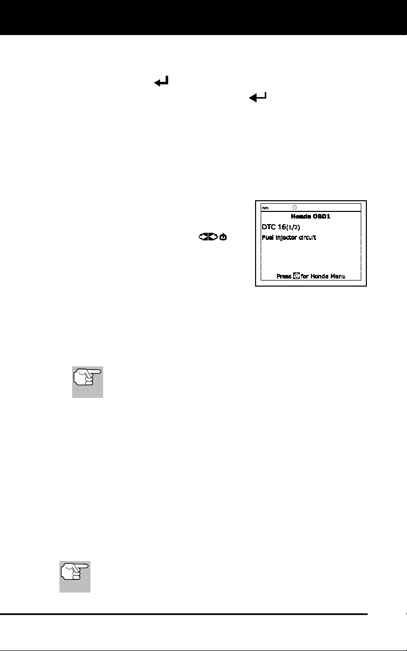
Honda OBD1 Systems
ERASING DTCs
64
Place the transmission in neutral.
Turn all vehicle accessories "OFF."
Press ENTER
to continue.
3. Highlight Read DTCs and press ENTER
.
4. When the Scan Tool is in the process of retrieving codes, a "One
moment please..." message shows.
If the Scan Tool fails to link to the vehicle's computer, a "Vehicle
is not responding" message shows.
- Verify the ignition is ON.
- Check the cable connections at the Scan Tool and at the
vehicle’s DLC.
- Turn the ignition OFF, wait 10-
12 seconds, then turn back ON
to reset the computer.
- Press POWER/LINK
and
repeat step 3 as necessary.
5. If the Scan Tool was able to link to the
vehicle successfully, the Scan Tool
displays the retrieved DTCs.
The Scan Tool will display a code only of codes are present in
the vehicle's computer memory. If no codes are present, a "No
DTC's are presently stored in the vehicle's computer" message
is displayed.
6. If more than one code was retrieved, press DTC/FF, as necessary,
to display additional codes one at a time.
In the case of long code definitions, a small arrow is shown
in the upper/lower right-hand corner of the code display
area to indicate the presence of additional information.
7. Disconnect the Scan Tool from the vehicle and turn the ignition key
OFF.
8. To prolong battery life, the Scan Tool automatically shuts "Off" after
approximately three minutes with no button activity. The DTCs
retrieved will remain in the Scan Tool's memory, and may be viewed
at any time. If the Scan Tool’s batteries are removed, or if the Scan
Tool is re-linked to a vehicle to retrieve codes, any prior codes in its
memory are automatically cleared.
9. Follow the testing and repair procedures outlined in the vehicle's
service repair manual to correct DTCs. Codes should be addressed
and eliminated in the order they were received, erasing and retesting
after each repair is made to be sure the fault was eliminated.
ERASING DTCs
When the Scan Tool's ERASE function is used to erase DTCs
from the vehicle's on-board computer, manufacturer specific
data (where applicable) is also erased.
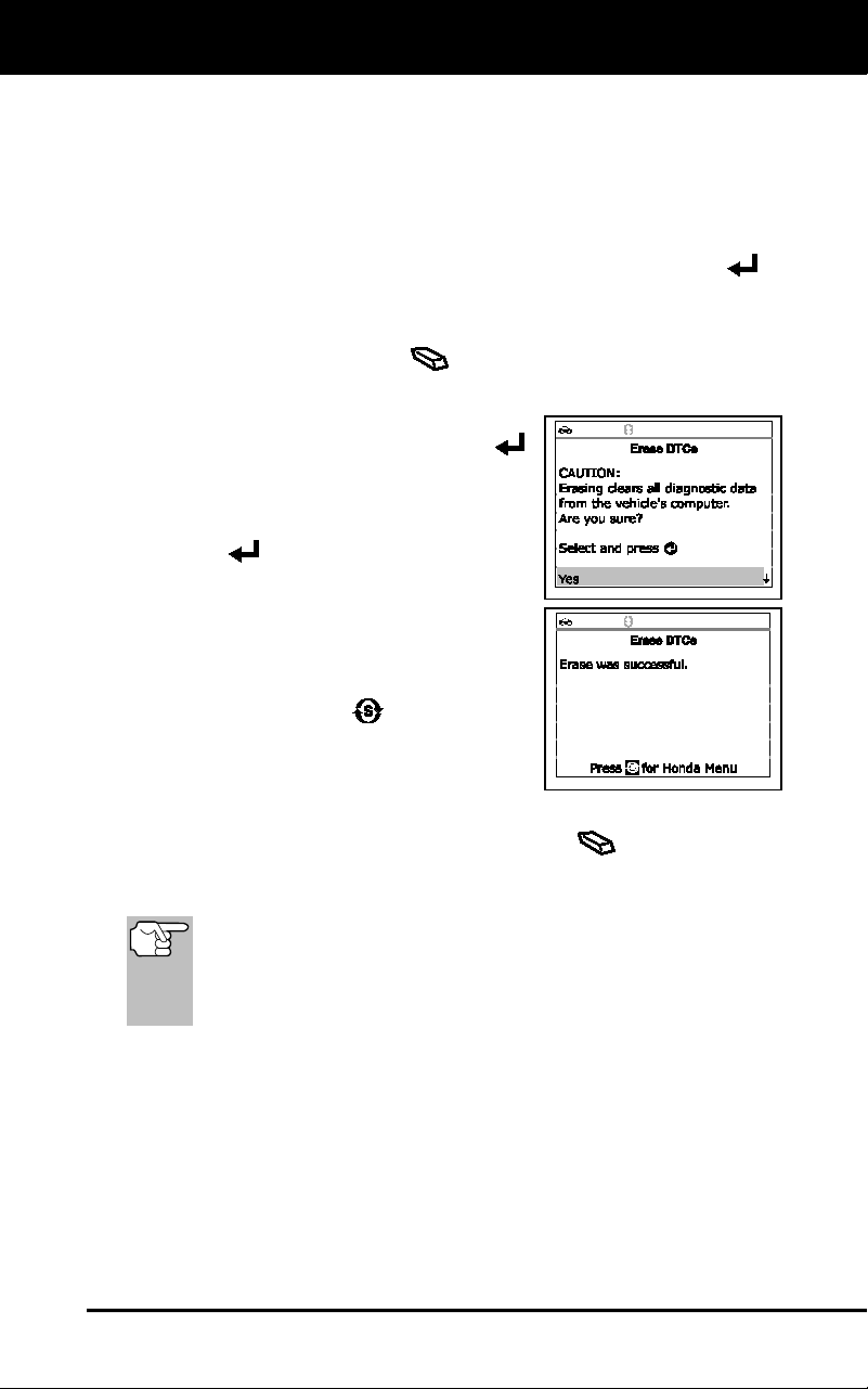
Honda OBD1 Systems
ERASING DTCs
65
If you plan to take the vehicle to a service center for repair, DO NOT
erase the codes from the vehicle's computer. If the codes are erased,
valuable information that might help the technician troubleshoot the
problem will also be erased.
Erase DTC’s from the computer’s memory as follows:
1. Connect the Scan Tool to the vehicle’s DLC. Press ENTER to
continue.
2. Turn the ignition ON. DO NOT start the engine.
3. Press and release ERASE
. A confirmation message shows on
the LCD display.
If you are sure you want to proceed,
select Yes, then press ENTER
to continue.
- If you do not want to proceed,
select No, then press ENTER
to exit the erase function.
4. If you chose to erase DTCs, a “One
moment please…” message displays
while the erase function is in progress.
If the erase was successful, a
confirmation message shows. Press
SYSTEM MENU
to return to the
Honda Menu.
If the erase was not successful, an
advisory message shows. Verify
that the Scan Tool is properly connected to the vehicle's DLC
and that the ignition is ON. Press ERASE
to continue. If the
erase process still does not complete, turn the ignition OFF, wait
10 seconds, then turn back ON and repeat steps 2 and 3.
Erasing DTCs does not fix the problem(s) that caused the
code(s) to be set. If proper repairs to correct the problem that
caused the code(s) to be set are not made, the code(s) will
appear again and the check engine light will illuminate as soon
as the problem that cause the DTC to set manifests itself.
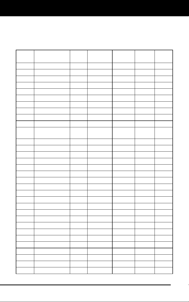
Toyota/Lexus OBD1 Systems
ON-BOARD VEHICLE DIAGNOSTICS - VEHICLES COVERED
66
VEHICLES COVERED
The following tables identify the Toyota and Lexus OBD1 vehicles that
are covered by the Scan Tool.
DLC 1 Cars
Year
Model
Eng.
Size
Eng.
Code
DOHC/
SOHC
Other
DLC
Type
1995
Camry Coupe
2.2L
5S-FE
DOHC
1
1992
Camry Sedan
2.2L
5S-FE
DOHC
1
1992
Camry Sedan
3.0L
2VZ-FE
DOHC
1
1993
Camry Sedan
3.0L
3VZ-FE
DOHC
1
1993
Camry Sedan
2.2L
5S-FE
DOHC
1
1994
Camry Sedan
2.2L
5S-FE
DOHC
1
1993
Celica
2.0L
3S-GTE
DOHC
Turbo
1
1993
Celica
2.2L
5S-FE
DOHC
1
1994
Celica
1.8L
7A-FE
DOHC
1
1994
Celica
2.2L
5S-FE
DOHC
1
1992 Celica
Convertible
2.2L 5S-FE DOHC A/T 1
1992
Celica Coupe
1.6L
4A-FE
DOHC
1
1992
Celica Coupe
2.2L
5S-FE
DOHC
A/T
1
1993
Celica Coupe
1.6L
4A-FE
DOHC
1
1995
Celica Coupe
1.8L
7A-FE
DOHC
1
1992
Celica Liftback
2.0L
3S-GTE
DOHC
Turbo
1
1992
Celica Liftback
2.2L
5S-FE
DOHC
1
1993
Corolla Sedan
1.6L
4A-FE
DOHC
1
1993
Corolla Sedan
1.8L
7A-FE
DOHC
1
1994
Corolla Sedan
1.6L
4A-FE
DOHC
1
1994
Corolla Sedan
1.8L
7A-FE
DOHC
1
1993
ES-300
3.0L
3VZ-FE
DOHC
1
1993
GS-300
3.0L
2JZ-GE
DOHC
1
1993
LS-400
4.0L
1UZ-FE
DOHC
1
1993
MR2
2.0L
3S-GTE
DOHC
Turbo
1
1993
MR2
2.2L
5S-FE
DOHC
1
1994
MR2
2.0L
3S-GTE
DOHC
Turbo
1
1994
MR2
2.2L
5S-FE
DOHC
1
1994
Paseo
1.5L
5E-FE
DOHC
1
1995
Paseo
1.5L
5E-FE
DOHC
1
1995
SC-300
3.0L
2JZ-GE
DOHC
1
1991
Supra
3.0L
7M-GTE
DOHC
Turbo
1
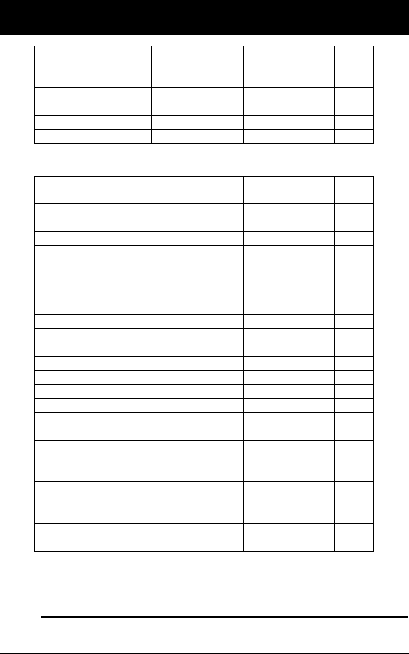
Toyota/Lexus OBD1 Systems
VEHICLES COVERED
67
Year
Model
Eng.
Size
Eng.
Code
DOHC/
SOHC
Other
DLC
Type
1991
Supra
3.0L
7M-GE
DOHC
1
1992
Supra
3.0L
7M-GTE
DOHC
Turbo
1
1992
Supra
3.0L
7M-GE
DOHC
1
1993
Tercel Sedan
1.5L
3E-E
SOHC
1
1994
Tercel Sedan
1.5L
3E
SOHC
1
DLC 2 Cars
Year
Model
Eng.
Size
Eng.
Code
DOHC/
SOHC
Other
DLC
Type
1989
Cressida
3.0L
7M-GE
DOHC
2
1990
Cressida
3.0L
7M-GE
DOHC
2
1991
Cressida
3.0L
7M-GE
DOHC
2
1992
Cressida
3.0L
7M-GE
DOHC
2
1993
Camry
3.0L
3VZ-FE
DOHC
2
1993
Supra
3.0L
2JZ-GTE
DOHC
Turbo
2
1993
Supra
3.0L
2JZ-GE
DOHC
2
1994
Camry
3.0L
3VZ-FE
DOHC
2
1994
Supra
3.0L
2JZ-GTE
DOHC
Turbo
2
1994
Supra
3.0L
2JZ-GE
DOHC
2
1995
Supra
3.0L
2JZ-GTE
DOHC
Turbo
2
1995
Supra
3.0L
2JZ-GE
DOHC
2
1992
SC-300
3.0L
2JZ-GE
DOHC
2
1990
ES-250
2.5L
2VZ-FE
DOHC
2
1991
ES-250
2.5L
2VZ-FE
DOHC
2
1992
ES-300
3.0L
3VZ-FE
DOHC
2
1992
SC-400
4.0L
1UZ-FE
DOHC
2
1991
LS-400
4.0L
1UZ-FE
DOHC
2
1992
LS-400
4.0L
1UZ-FE
DOHC
2
1993
SC-400
4.0L
1UZ-FE
DOHC
2
1994
SC-400
4.0L
1UZ-FE
DOHC
2
1994
SC-300
3.0L
2JZ-GE
DOHC
2
1993
SC-400
4.0L
1UZ-FE
DOHC
2
1994
GS-300
3.0L
2JZ-GE
DOHC
2
1993
SC-300
3.0L
2JZ-GE
DOHC
2
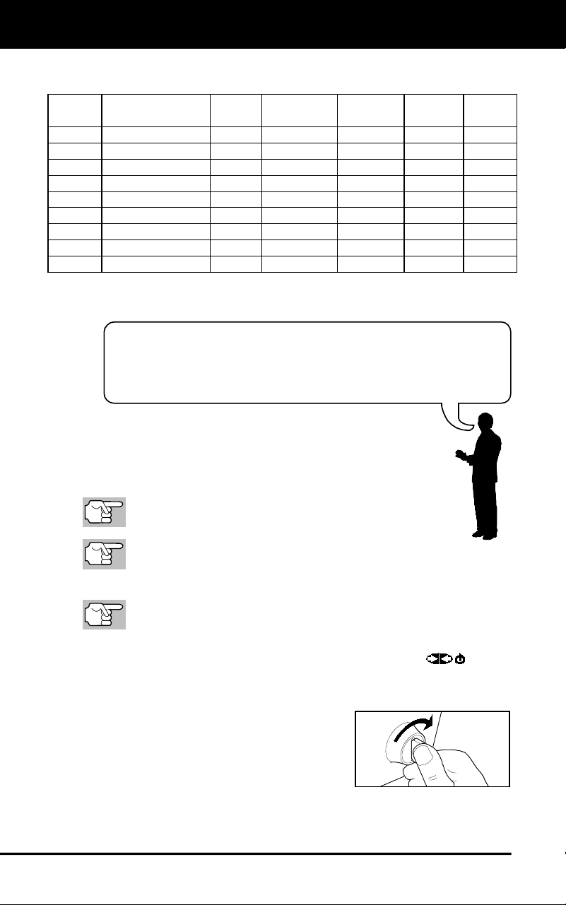
Toyota/Lexus OBD1 Systems
CODE RETRIEVAL PROCEDURE
68
Retrieving and using Diagnostic Trouble Codes (DTCs) for
troubleshooting vehicle operation is only one part of an
overall diagnostic strategy.
DLC 1 Light Trucks
Year
Model
Eng.
Size
Eng.
Code
DOHC/
SOHC
Other
DLC
Type
1992
Previa
2.4L
2TZ-FE
DOHC
1
1993
Previa
2.4L
2TZ-FE
DOHC
1
1994
Previa
2.4L
2TZ-FE
DOHC
1
1994
T100
3.0L
3VZ-FE
SOHC
1
1995
4 Runner
2.4L
22R-E
SOHC
1
1995
4 Runner
3.0L
3VZ-FE
SOHC
1
1995
Pickup
2.4L
22R-E
SOHC
1
1995
Pickup
3.0L
3VZ-FE
SOHC
1
1995
Previa
2.4L
2TZ-FE
DOHC
1
CODE RETRIEVAL PROCEDURE
Never replace a part based only on the DTC definition.
Each DTC has a set of testing procedures, instructions and
flow charts that must be followed to confirm the location of
the problem. Always refer to the vehicle's service manual for
detailed testing instructions.
Check your vehicle thoroughly before performing any
test.
ALWAYS observe safety precautions whenever working on a
vehicle.
1. Locate the vehicle's Data Link Connector (DLC).
Some DLCs have a plastic cover that must be removed before
connecting the Scan Tool's cable connector.
2. Connect the Scan Tool (with the Toyota Connector Cable Adaptor
attached) to the vehicle’s DLC. Press POWER/LINK
to turn
the Scan Tool ON.
The Toyota Menu displays.
Turn ignition ON and start engine.
Warm engine to operating tempera-
ture. (Shut engine off after warm up,
then turn the ignition back ON).
Make sure throttle is closed.
Set gear lever in "park" (for automatic transmissions) or “neutral”
for manual transmissions.
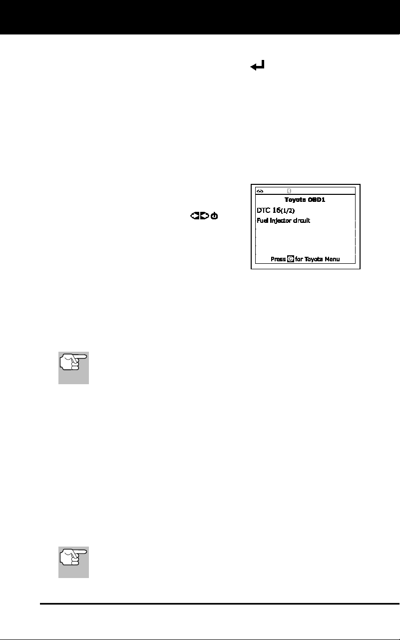
Toyota/Lexus OBD1 Systems
ERASING DTCs
69
Turn off all accessories.
3. Highlight Read DTCs, then press ENTER
.
The Scan Tool will begin the code retrieval process.
4. When the Scan Tool is in the process of retrieving codes, a "One
moment please..." message shows.
If the Scan Tool fails to link to the vehicle’s computer a “Vehicle
is not responding” message shows.
- Verify the ignition is ON.
- Check the cable connections at the Scan Tool and at the
vehicle’s DLC.
- Turn the ignition OFF, wait 10-12
seconds, then turn back ON to
reset the computer.
- Press POWER/LINK
.
5. If the Scan Tool was able to link to the
vehicle successfully a "Code retrieval
was successful..." message shows
temporarily, followed by any retrieved
DTCs.
The Scan Tool will display a code only if codes are present in
the vehicle's computer memory. If no codes are present, a "No
DTC's are presently stored in the vehicle's computer" message
is displayed.
6. If more than one code was retrieved press DTC/FF, as necessary,
to display additional codes one at a time.
In the case of long code definitions, a small arrow is shown in the
upper/lower right-hand corner of the code display area to indicate
the presence of additional information.
7. Disconnect the Scan Tool from the vehicle and turn the ignition key
OFF.
8. To prolong battery life, the Scan Tool automatically shuts "Off" after
approximately three minutes with no button activity. The DTCs
retrieved will remain in the Scan Tool's memory, and may be viewed
at any time. If the Scan Tool’s batteries are removed, or if the Scan
Tool is re-linked to a vehicle to retrieve codes, any prior codes in its
memory are automatically cleared.
9. Follow the testing and repair procedures outlined in the vehicle's service
repair manual to correct "hard" DTCs. Codes should be addressed and
eliminated in the order they were received, erasing and retesting after
each repair is made to be sure the fault was eliminated.
ERASING DTCs
When the Scan Tool's ERASE function is used to erase DTCs
from the vehicle's on-board computer, manufacturer specific
data (where applicable) is also erased.
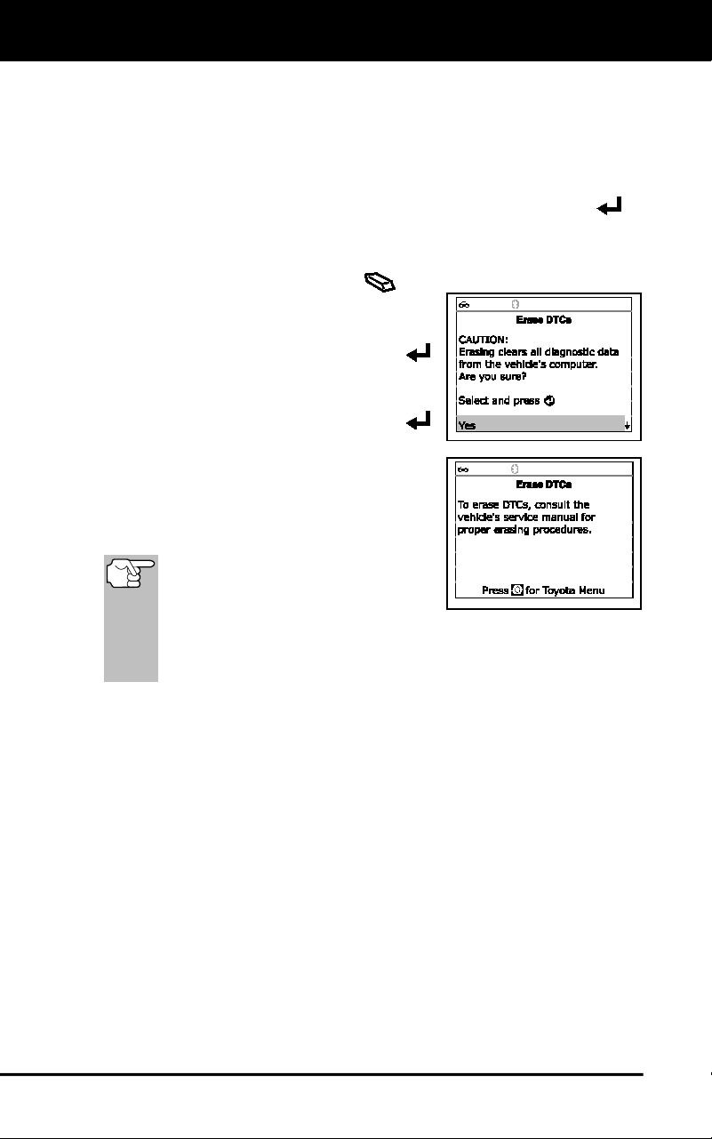
Toyota/Lexus OBD1 Systems
ERASING DTCs
70
If you plan to take the vehicle to a service center for repair, DO NOT
erase the codes from the vehicle's computer. If the codes are erased,
valuable information that might help the technician troubleshoot the
problem will also be erased.
Erase DTC’s from the computer’s memory as follows:
1. Connect the Scan Tool to the vehicle’s DLC. Press ENTER to
continue.
2. Turn the ignition ON. DO NOT start the engine.
3. Press and release ERASE
. A
confirmation message shows.
If you are sure you want to proceed,
select Yes, then press ENTER
to continue.
- If you do not want to proceed,
select No, then press ENTER
to exit the erase function.
4. If you chose to erase DTCs, the “To erase
DTC’s consult the vehicle’s service repair
manual...” screen displays. You must
consult the vehicle’s service repair manual
for procedures to erase DTCs.
Erasing DTCs does not fix the
problem(s) that caused the code(s)
to be set. If proper repairs to
correct the problem that caused
the code(s) to be set are not made, the code(s) will appear
again and the check engine light will illuminate as soon as the
problem that cause the DTC to set manifests itself.
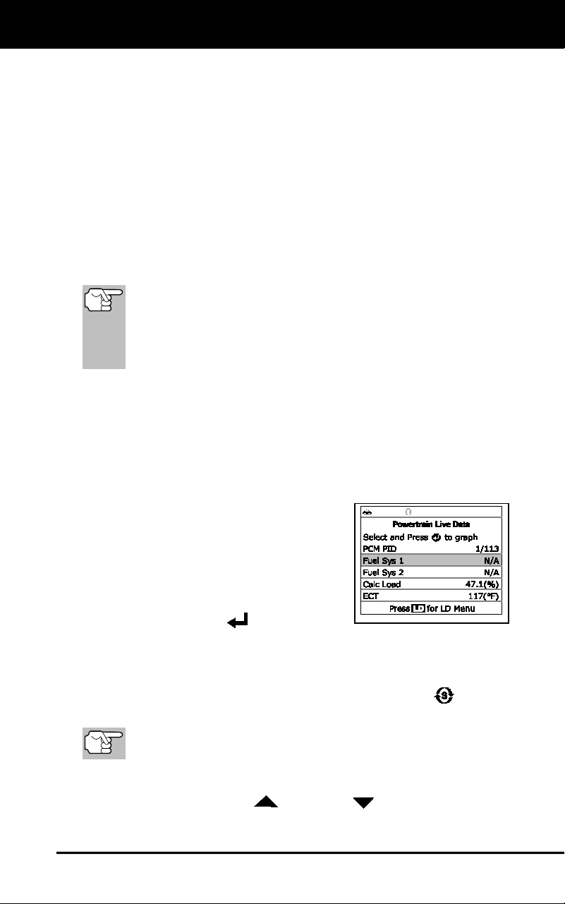
Live Data Mode
VIEWING LIVE DATA
71
The Scan Tool lets you view "real-time" Live Data. This information
includes values (volts, rpm, temperature, speed etc.) and system status
information (open loop, closed loop, fuel system status, etc.) generated by
the various vehicle sensors, switches and actuators. These are the same
signal values generated by the sensors, actuators, switches and/or
vehicle system status information used by the vehicle's computer when
calculating and conducting system adjustments and corrections.
The real time (Live Data) vehicle operating information (values/status)
that the computer supplies to the Scan Tool for each sensor, actuator,
switch, etc. is called Parameter Identification (PID) Data.
Each PID (sensor, actuator switch, status, etc.) has a set of operating
characteristics and features (parameters) that serve to identify it. The
Scan Tool displays this information for each sensor, actuator, switch or
status that is supported by the vehicle under test.
WARNING: If the vehicle must be driven in order to perform a
troubleshooting procedure, ALWAYS have a second person
help you. One person should drive the vehicle while the other
person observes the Scan Tool data. Trying to drive and
operate the Scan Tool at the same time is dangerous, and
could cause a serious traffic accident.
VIEWING LIVE DATA
1. While linked to the vehicle, start the engine, then press LD.
2. A “One moment please . . .” message displays while the Scan Tool
establishes communication with the vehicle.
If the Scan Tool fails to establish communication with the vehicle,
a “Communication Error” message displays.
- Ensure your vehicle is OBD2
compliant.
- Verify the connection at the DLC,
and verify the ignition is ON.
- Turn the ignition OFF, wait 5
seconds, then back ON to reset
the computer.
- Press ENTER
to continue.
3. Real-time Live Data (PID) information supported by the vehicle
under test displays.
If Live Data is not supported by the vehicle under test, an
advisory message displays. Press SYSTEM MENU
to return
to the System Menu. Live Data is not available for your vehicle.
The values for the various PIDS displayed may change as the
vehicle's operating conditions change.
4. Only a limited amount of PID data can be displayed on the screen at
one time. If additional PID data is available, a small arrow is shown
on the display. Press UP
and DOWN , as necessary, to view
all available PID data.
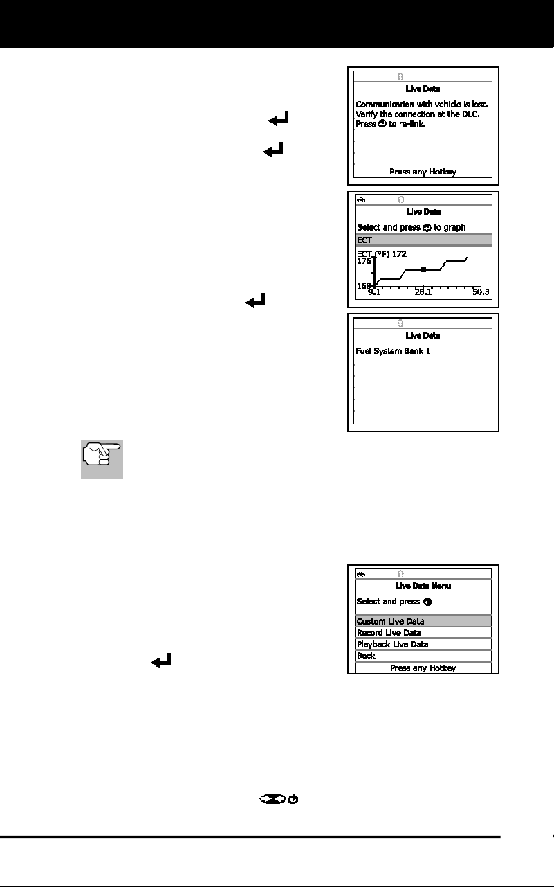
Live Data Mode
CUSTOMIZING LIVE DATA (PIDs)
72
If communication with the vehicle is
lost while viewing Live Data, an
advisory message displays.
5. Press and release ENTER
to view
the currently selected PID in “graph” mode.
Press and release ENTER
again to
return to the PID list.
You can display a maximum of two
PIDs in "graph" mode at any given
time.
With two PID shown in "graph"
mode, press and hold LD to
superimpose one graph on the other.
Release LD to separate the graphs.
6. Press and hold ENTER
to view the
“expanded” definition for the currently
selected PID. Release to return to the PID
list.
7. If you experience vehicle problems,
view and/or compare the Live Data (PID)
information displayed on the Scan Tool
to specifications in the vehicle's repair
manual.
If desired, you can "customize" the Live Data display to show only
those PIDs you are interested in viewing. See Customizing Live
Data (PIDs) below for details.
CUSTOMIZING LIVE DATA (PIDs)
You can customize the Live Data display by placing the Scan Tool in
"Custom Live Data" mode and selecting only the PIDs that you wish to
display.
1. With the Scan Tool in Live Data mode
(see VIEWING LIVE DATA on page 71),
press and hold LD until the Live Data
Menu displays, then release
2. Select Custom Live Data, then press
ENTER
.
If the Scan Tool fails to establish communication with the vehicle,
a “Communication Error” message displays.
- Ensure your vehicle is OBD2 compliant.
- Verify the connection at the DLC, and verify the ignition is ON.
- Turn the ignition OFF, wait 5 seconds, then back ON to reset
the computer.
- Press POWER/LINK
to continue.
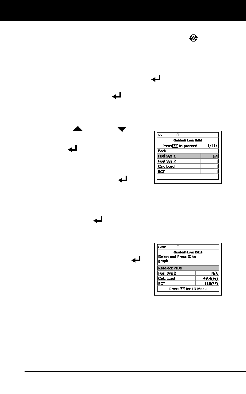
Live Data Mode
RECORDING (CAPTURING) LIVE DATA
73
If Live Data is not supported by the vehicle under test, an
advisory message displays. Press SYSTEM MENU
to return
to the System Menu.
If custom Live Data was previously configured, the Select PIDs
to Use screen displays.
- To use the existing custom Live data selections, select Use
existing PIDs, then press ENTER
. Proceed to step 5.
- To configure new custom Live Data, select Select new PIDs,
then press ENTER
. The Custom Live Data menu displays.
Proceed to step 3.
If custom Live Data was not previously selected, the Custom
Live Data menu displays. Proceed to step 3.
3. Press UP
and DOWN to scroll
through the available PIDs. When a PID
you wish to display is highlighted, press
ENTER
(a "checkmark" shows to
confirm your selection). Repeat until only
the PIDs you want to display are selected.
To deselect a PID, highlight the PID,
then press ENTER
. The
checkmark is removed.
4. When you are finished making your selection(s), press LD to
continue.
If no PIDs have been selected, an advisory message displays.
Press ENTER
to return to the Custom Live Data menu.
5. The Scan Tool is now in "Custom Live Data" mode. Only the PIDs
you selected are shown.
To change the current custom Live
Data selections, select Reselect
PIDs, then press ENTER
to
return to the Custom Live Data
menu. Repeat step 3.
6. To exit the "Custom Live Data" mode,
press LD to return to the Live Data Menu.
RECORDING (CAPTURING) LIVE DATA
You can record and save several frames of Live Data information for
each PID supported by the vehicle in the Scan Tool's memory.
There are two ways that the Scan Tool can record Live Data:
Record by DTC Trigger
Record by Manual Trigger
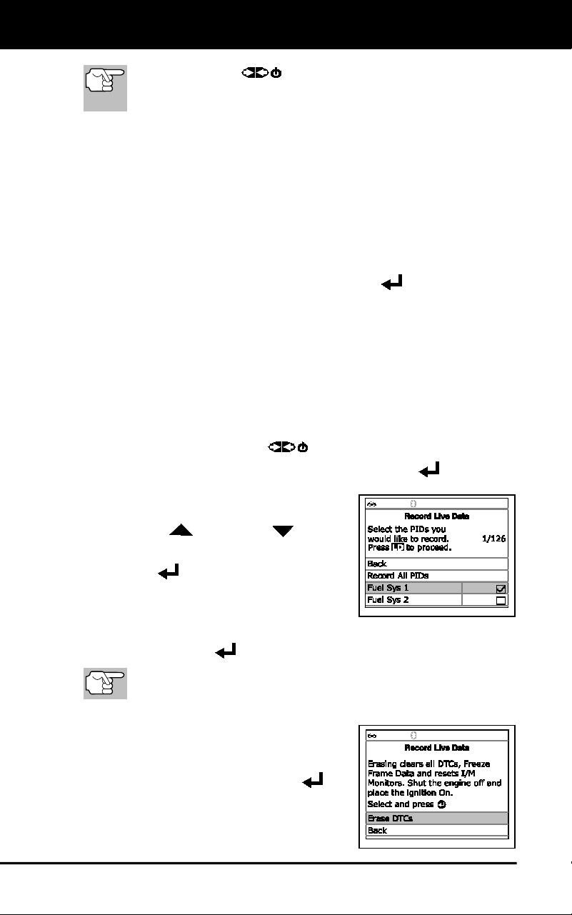
Live Data Mode
RECORDING (CAPTURING) LIVE DATA
74
If POWER/LINK is pressed at any time while in Live
Data mode, any recorded Live Data will be erased from the
Scan Tool’s memory.
Record by DTC Trigger
This function automatically records Live Data information when a DTC
sets and saves it in the Scan Tool’s memory. The recorded (captured)
data can be a valuable troubleshooting aid, particularly if you are
experiencing a fault that is causing a DTC to set. The Scan Tool can
record approximately 100 frames of Live Data.
1. With the Scan Tool in Live Data mode (see VIEWING LIVE DATA
on page 71), press and hold the LD button until the Live Data Menu
displays, then release the LD button.
2. Select Record Live Data, then press ENTER
.
The Record Live Data Menu displays.
If the Scan Tool fails to establish communication with the vehicle,
a “Communication Error” message displays.
- Ensure your vehicle is OBD2 compliant.
- Verify the connection at the DLC, and verify the ignition is ON.
- Turn the ignition OFF, wait 5 seconds, then back ON to reset
the computer.
- Press POWER/LINK
to continue.
3. Select Record by DTC Trigger, then press ENTER
.
The Select PIDs to Record screen
displays.
4. Press UP
and DOWN to scroll
through the available PIDs. When a PID
you wish to record is highlighted, press
ENTER
(a “checkmark” shows to
confirm your selection). Repeat the
procedure until only the PIDs you want
to record are selected.
To deselect a currently selected PID, highlight the PID, then
press ENTER
. The checkmark is removed.
To record all PIDs, select Record All PIDs, the press LD to
continue.
5. When you are finished making your selections, press LD to continue.
If DTCs are presently stored in the
vehicle’s computer, an advisory
message displays. Select Erase
DTCs, then press ENTER
. A
“One moment please…” message
displays while DTCs are erased
from the vehicle’s computer.
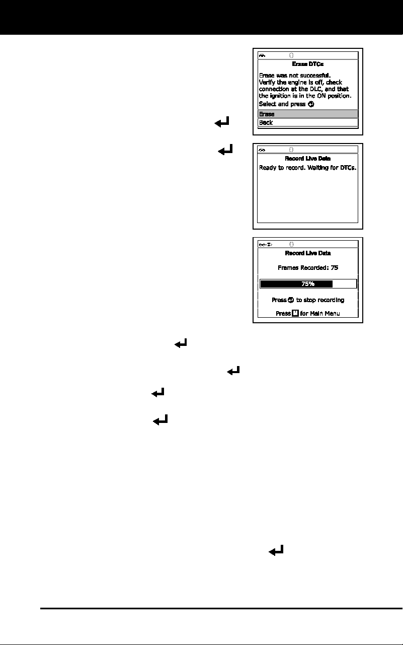
Live Data Mode
RECORDING (CAPTURING) LIVE DATA
75
If the erase was not successful, an
advisory message displays.
- To retry the erase process, verify
that the Scan Tool is properly
connected to the vehicle’s DLC
and that the ignition is on. Select
Erase, then press ENTER
.
- To exit the record function, select
Back, then press ENTER
to
return to the Record Live Data
menu.
6. Put the engine in the operating
condition that causes the DTC to set.
If necessary, drive the vehicle until
you reach the vehicle speed at
which the problem occurs.
7. When the Scan Tool detects a fault that
causes a DTC to set, it automatically
records and saves approximately 100
frames of Live Data information in its
memory for each PID selected.
A progress message shows on the
display.
- You can stop and save recorded Live Data at any time by
pressing ENTER
.
When recording is complete, a confirmation screen displays.
Select Yes and press ENTER
to playback Live Data (see
LIVE DATA PLAYBACK on page 77 for details) or select No and
press ENTER
to return to the Live Data menu, as desired.
If recording was not successful, an advisory message displays.
Press ENTER
to return to the Record Live Data menu.
Record by Manual Trigger
This option lets you select the precise time at which the Live Data recording
will occur. Record by Manual Trigger can be a very valuable tool when
troubleshooting intermittent problems that do not meet the requirements for
a DTC to set. The Scan Tool can record approximately 100 frames of Live
Data.
1. With the Scan Tool in Live Data mode (see VIEWING LIVE DATA
on page 71), press and hold LD until the Live Data Menu displays,
then release.
2. Select Record Live Data, then press ENTER
.
The Record Live Data Menu displays.
If the Scan Tool fails to establish communication with the vehicle,
a “Communication Error” message displays.
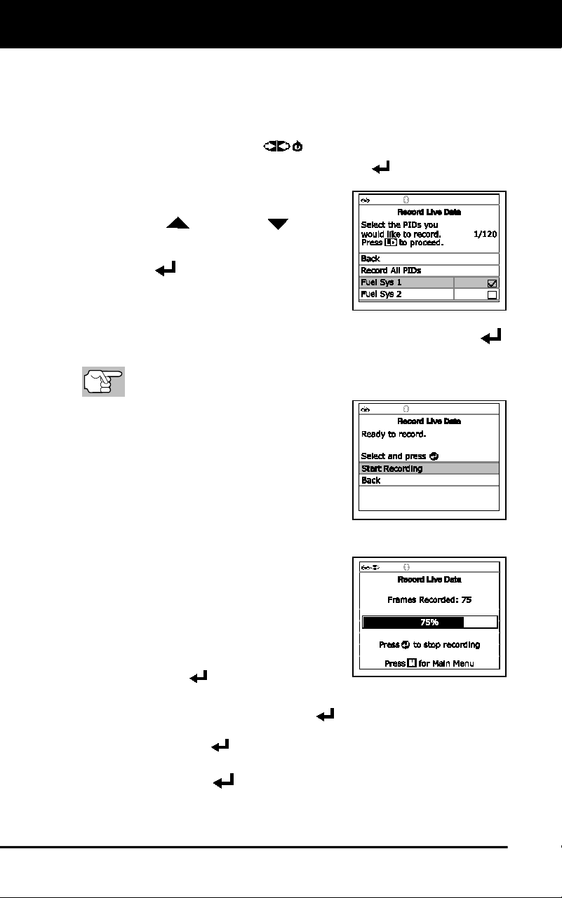
Live Data Mode
RECORDING (CAPTURING) LIVE DATA
76
- Ensure your vehicle is OBD2 compliant.
- Verify the connection at the DLC, and verify the ignition is ON.
- Turn the ignition OFF, wait 5 seconds, then back ON to reset
the computer.
- Press POWER/LINK
to continue.
3. Select Record Manually, then press ENTER
.
The Select PIDs to Record screen
displays.
4. Press UP
and DOWN to scroll
through the available PIDs. When a PID
you wish to record is highlighted, press
ENTER
(a “checkmark” shows to
confirm your selection). Repeat until
only the PIDs you want to record have
all been selected.
To deselect a PID, highlight the PID, then press ENTER .
The checkmark is removed.
To record all PIDs, select Record All PIDs, the press LD to
continue.
5. When you are finished making your
selections, press LD to continue.
The Record Live Data screen
displays.
Highlight Start Recording. Put the
engine in the operating condition
where the problem manifests itself.
- If necessary, drive the vehicle until you reach the vehicle
speed at which the problem
occurs.
6. When the problem occurs, press and
release LD.
A progress message shows on the
display.
- You can stop and save recorded
Live Data at any time by pressing
ENTER
.
When recording is complete, a confirmation screen displays.
Select Yes and press ENTER
to playback Live Data (see
LIVE DATA PLAYBACK on page 77 for details) or select No and
press ENTER
to return to the Live Data menu, as desired.
If recording was not successful, an advisory message displays.
Press ENTER
to return to the Record Live Data menu.
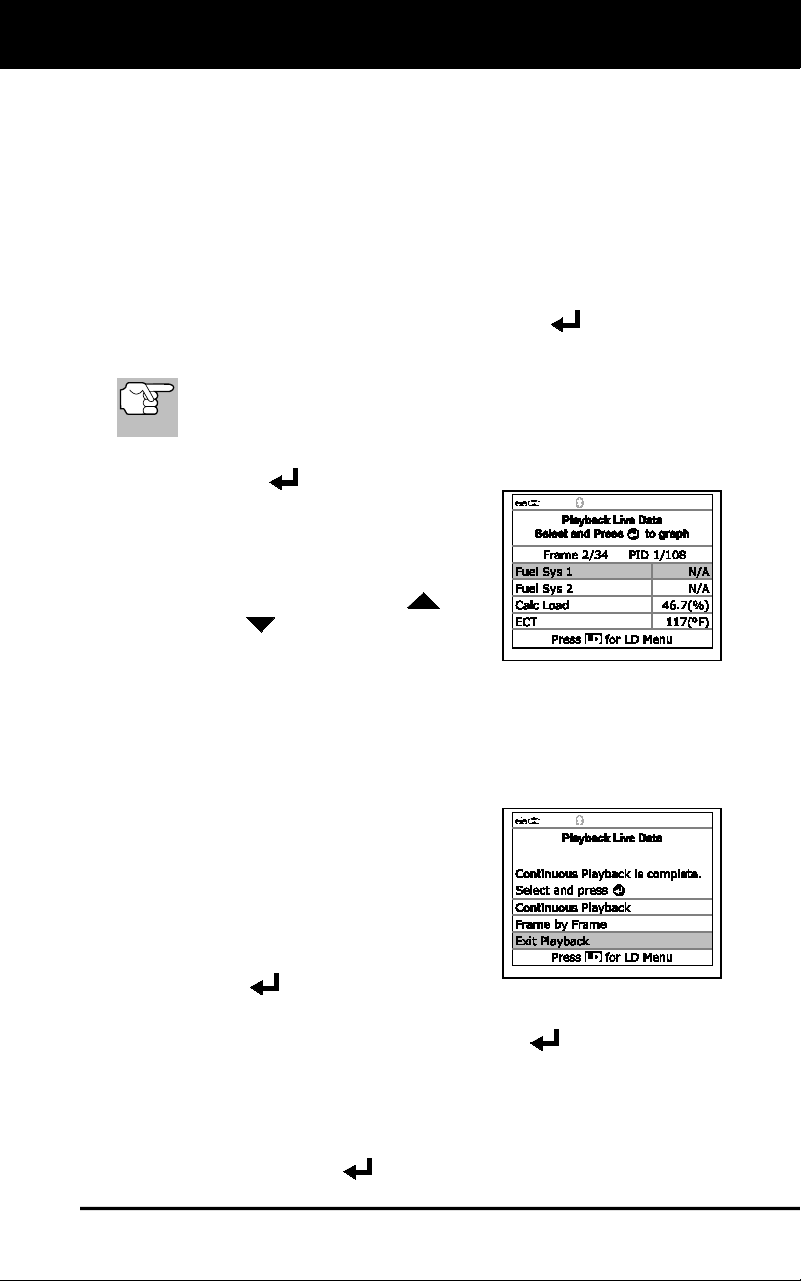
Live Data Mode
LIVE DATA PLAYBACK
77
LIVE DATA PLAYBACK
Once Live Data has been recorded, it is saved in the Scan Tool's
memory. You can view recorded Live Data immediately after recording
by selecting Yes from the Record Live Data confirmation screen (see
RECORDING (CAPTURING) LIVE DATA on page 73 for more
information), or you can view it later using the "Playback" function.
1. With the Scan Tool connected to the vehicle and in Live Data mode
(see VIEWING LIVE DATA on page 71), press and hold LD until the
Live Data Menu displays, then release.
2. Select Playback Live Data, then press ENTER
.
The Playback Live Data menu displays.
When you select Yes from the Record Live Data confirmation
screen, the Scan Tool enters the "Live Data Playback" mode,
and the Playback Live Data menu displays.
3. Select Continuous Playback or Frame by Frame, as desired, then
press ENTER
.
Only a limited amount of PID data
can be displayed on the screen at
one time. If additional PID data is
available, a small arrow is shown on
the display. Press UP
and
DOWN
, as necessary, to view
all available PID data.
When viewing recorded Live Data, look for any irregularities in
any of the PID values/signal information (LTFT %, RPM, MAP,
TEMP, etc.). If any PIDs are not within specification, or
irregularities are detected, follow the procedures in the vehicle's
service repair manual to perform additional troubleshooting and
repair.
4. When you select Continuous Playback,
the Scan Tool plays recorded data at a
rate of one frame / 15 seconds. When
playback is finished, a Playback
Complete message displays.
To play the data back again, select
Continuous Playback or Frame by
Frame, as desired, then press
ENTER
.
To exit Live Data Playback mode and return to Live Data mode,
select Exit Playback, then press ENTER
.
5. When Frame by Frame is selected, you must scroll the individual
frames manually.
When you have viewed all PID information for the current frame
of Live Data, select Next Frame or Previous Frame, as desired,
then press ENTER
.

Live Data Mode
LIVE DATA PLAYBACK
78
To exit Live Data Playback mode, select Exit Playback, then
press ENTER
.
If there is no Live Data currently stored in the Scan Tool's
memory, an advisory message shows on the display. Press
LD to exit the "Live Data Playback" mode.
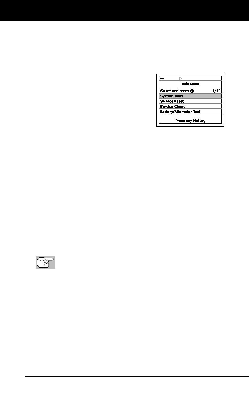
Additional Tests
SYSTEM TEST MENU
79
In addition to retrieving Diagnostic Trouble Codes (DTCs), you can use
the Scan Tool to perform additional diagnostic tests, to view diagnostic
and vehicle information stored in your vehicle's on-board computer, and
to configure the Scan Tool for your particular needs. Additional tests and
related functions are accessed through the Main Menu. The following
functions are available:
System Tests – Displays the System
Test menu, which lets your retrieve and
view results for the O2 Sensor Test and
OBD Monitor Test, and lets you initiate
a test of the vehicle’s EVAP system.
Service Reset – Lets you reset the Oil
Maintenance Light.
Service Check – Lets you view the
current engine oil level and oil life
remaining.
Battery/Alternator Test – Performs a check of the vehicle’s battery
and alternator system to ensure the system is operating within
acceptable limits.
DLC Locator – Lets you find the location of the Data Link
Connector (DLC) for a specified vehicle.
Vehicle Information – Displays the Vehicle Info menu, which lets
you retrieve and view reference information for the vehicle under
test.
Firmware Version – Displays the Scan Tool’s firmware version.
Tool Library – Displays the Tool Library menu, which provides
access to OBD1 and OBD2 DTC libraries and to definitions for
Monitor icons and LED indications.
Tool Settings – Displays the Tool Settings menu, which lets you
make several adjustments and settings to configure the Scan Tool
to your particular needs.
The System Tests and Vehicle Information options are
shown only when the Scan Tool is in Global OBD2 mode.
SYSTEM TEST MENU
Additional tests are accessed through the Mode Test menu. The
following functions are available:
O2 Sensor Test - Retrieves and displays O2 sensor monitor test
results from your vehicle's on-board computer.
OBD Monitor Test - Retrieves and displays test results for
emission-related powertrain components and systems that are not
continuously monitored.
EVAP Test - Performs a leak test for the vehicle's EVAP system.
1. While linked to the vehicle, press M.
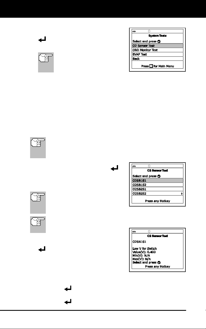
Additional Tests
SYSTEM TEST MENU
80
The Main Menu displays.
2. Select System Tests, then press ENTER
.
The System Test menu displays.
If System Tests is not shown
on the Main Menu, the System
Tests functions are not
available for your vehicle.
O2 Sensor Test
OBD2 regulations require that applicable vehicles monitor and test operation
of the oxygen (O2) sensors to identify problems that can affect fuel
efficiency and vehicle emissions. These tests are performed automatically
when engine operating conditions are within predefined limits. Results of
these tests are stored in the on-board computer's memory.
The O2 Sensor Test function lets you retrieve and view O2 sensor
monitor test results for the most recently completed tests from your
vehicle's on-board computer.
The scan tool does not perform O2 sensor tests, but retrieves
results from the most recently performed O2 sensor tests from
the on-board computer's memory. You may retrieve O2 sensor
test results for only one test of one sensor at any given time.
3. From the System Test menu, select O2
Sensor Test, then press ENTER
.
4. A "One moment please..." message
displays, followed by the select sensor
screen.
If O2 sensor test data is not
presently stored in the vehicle’s
computer, an advisory message
displays. Press M to return to the Main Menu.
If O2 sensor tests are not supported by the vehicle under test,
an advisory message displays. Press M to return to the Main
Menu.
5. Select the O2 sensor for which you wish
to view test results, then press ENTER
to display the test results.
6. When test results have been retrieved,
data for the selected sensor test will
show on the Scan Tool's display.
7. When you have finished viewing the retrieved test data:
To view test results for the next sensor, select Next, then press
ENTER
.
To return to the Select Sensor screen, select Back, then press
ENTER
.
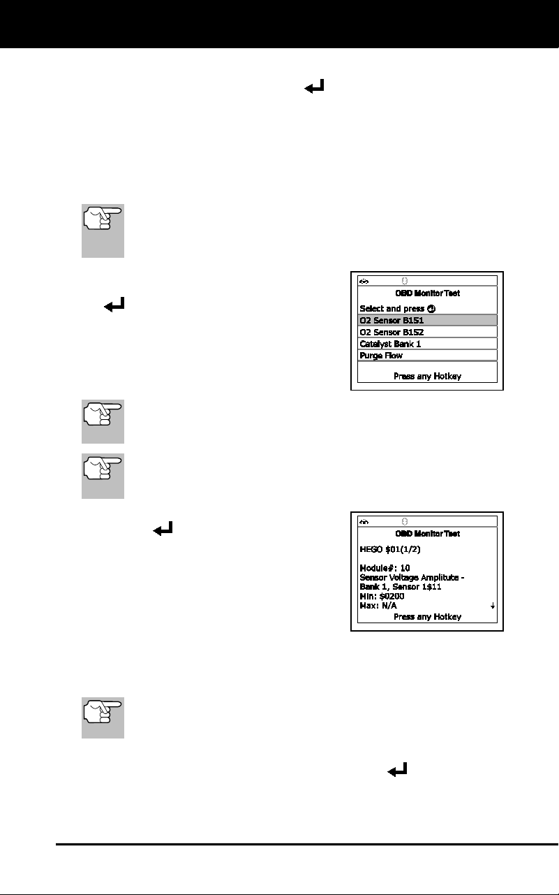
Additional Tests
SYSTEM TEST MENU
81
8. When you have finished viewing test data for all desired sensors,
select Back, then press ENTER
to return to the System Test
menu; or, press M to return to the Main Menu.
OBD Monitor Test
The OBD Monitor Test function retrieves and displays test results for
emission-related powertrain components and systems that are not
continuously monitored. The tests available are determined by the
vehicle manufacturer.
The Scan Tool does not perform the OBD monitor test, but
retrieves results from the most recently performed tests from
the on-board computer’s memory. You may retrieve OBD
monitor test results for only one test at any given time.
1. From the System Test menu, select
OBD Monitor Test, then press ENTER
.
2. A “One moment please. . .” message
displays, followed by the Select Test
screen. (Refer to the vehicle’s service
repair manual for information related to
non-continuous tests.)
If OBD monitor test data is not presently stored in the vehicle’s
computer, an advisory message displays. Press M to return to
the Main Menu.
If OBD monitor tests are not supported by the vehicle under test,
an advisory message displays. Press M to return to the Main
Menu.
3. Select the desired test, then press
ENTER
to display the test results.
The display shows the following
information:
Test ID number
Module ID number
Component ID number
Min or Max test limit (Only one test limit, either Min or Max, is
shown for any given test.)
Test Value and status
Status is calculated by the Scan Tool by comparing the Test
Value against the displayed test limit (either Min or Max).
Status is shown as either Low, High or OK.
4. When you have finished viewing the retrieved test data, select Back
on the Select Test screen, then press ENTER
to return to the
System Test menu; or, press M to return to the Main Menu.
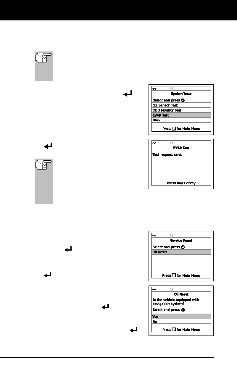
Additional Tests
RESETTING THE OIL MAINTENANCE LIGHT
82
EVAP Test
The EVAP Test function lets you initiate a leak test for the vehicle's
EVAP system.
The Scan Tool does not perform the leak test, but signals to
vehicle's on-board computer to initiate the test. The vehicle
manufacturer determines the criteria and method for stopping the
test once it has been started. Refer to the vehicle's service repair
manual to determine the procedures necessary to stop the test.
1. From the System Test menu, select
EVAP Test, then press ENTER
.
2. A "One moment please..." message
displays.
3. When the EVAP leak test has been
initiated by the vehicle's on-board
computer, a confirmation message
displays. Select Back, then press ENTER
to return to the System Test menu; or,
press M to return to the Main Menu.
Some vehicle manufacturers do not
allow diagnostic tools or other
external devices to control vehicle
systems. If the EVAP Test is not
supported by the vehicle under test,
an advisory message displays. Press the M button to return to
the Main Menu.
RESETTING THE OIL MAINTENANCE LIGHT
1. While linked to the vehicle, press M.
The Main Menu displays.
2. Select Service Reset, then press
ENTER to continue.
The Service Reset screen displays.
3. Select Oil Reset, then press ENTER
.
The Oil Reset screen displays.
If the vehicle under test is equipped
with a navigation system, select Yes,
then press ENTER
to continue.
If the vehicle under test is not
equipped with a navigation system,
select No, then press ENTER
to
continue.
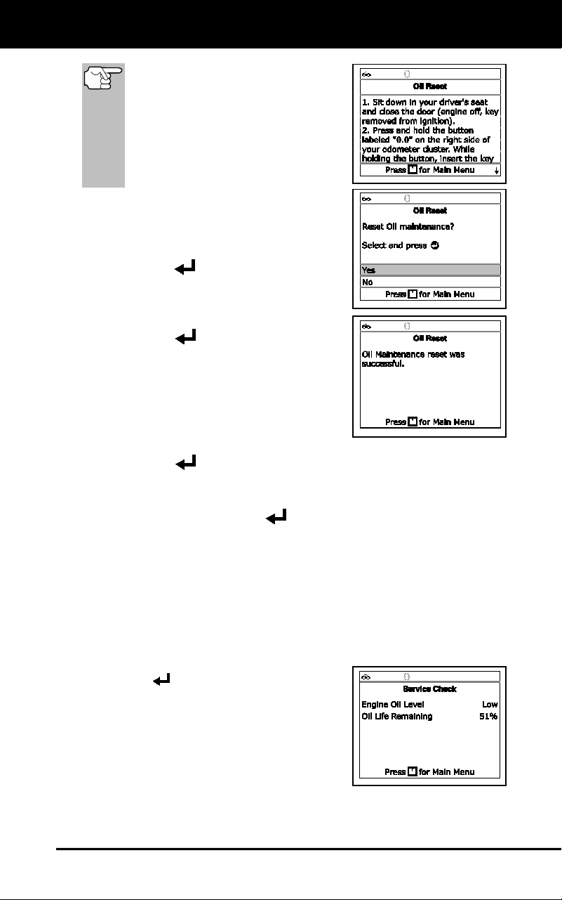
Additional Tests
PERFORMING A SERVICE CHECK
83
If the Scan Tool cannot reset the
Oil Maintenance Light, an “instruc-
tional” dialog displays, showing
the manual procedures for reset-
ting the indicator light. When
finished viewing the instructions,
press M to return to the Main
Menu.
4. The Reset Oil Maintenance Indicator
screen displays.
If you do not wish to proceed with the
reset process, select No, then press
ENTER
to return to the System
Menu.
If you wish to proceed with the reset
process, select Yes, then press
ENTER
to continue.
5. When the reset process has competed,
a confirmation message displays. Press
M to return to the Main Menu.
If the oil reset was not successful,
an advisory message displays.
To perform the oil reset by procedure, select Yes, then press
ENTER
. An “instructional” message displays, showing the
manual procedures for resetting the indicator light.
If you do not wish to perform the oil reset by procedure, select
No, then press ENTER
to return to the Main Menu.
PERFORMING A SERVICE CHECK
The Service Check function lets you check the current oil level and oil
life.
1. While linked to the vehicle, press M.
The Main Menu displays.
2. Select Service Check, then press
ENTER
.
The Service Check screen displays.
The screen shows the current
Engine Oil Level and Oil Life
Remaining.
3. When you have finished viewing the
information, press M to return to the
Main Menu.
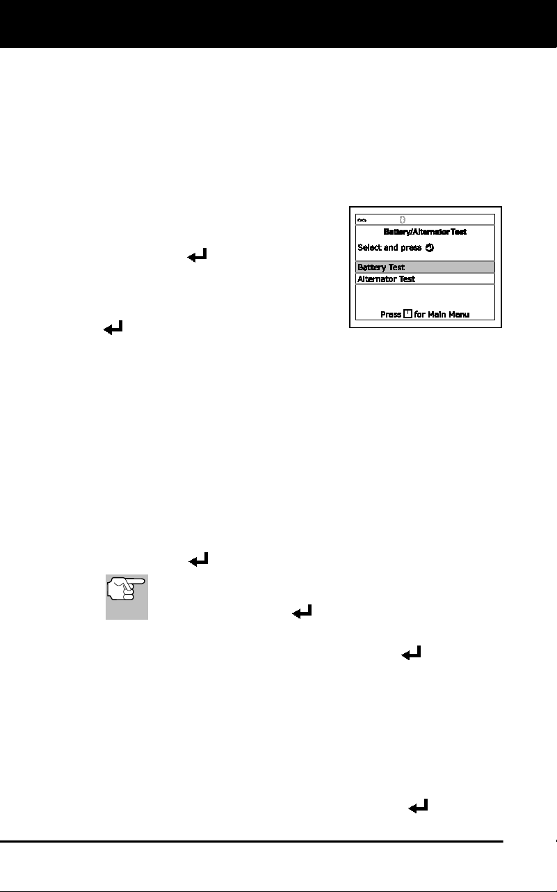
Additional Tests
BATTERY/ALTERNATOR TEST
84
BATTERY/ALTERNATOR TEST
The Scan Tool can perform a check of the vehicle’s battery and
alternator system to ensure the system is operating within acceptable
limits. You can perform a battery check only, or an alternator system
(battery and alternator) check.
To perform a battery check ONLY:
1. Press M and release.
The Main Menu displays.
2. Select Battery/Alternator Test, then
press ENTER
.
The Battery/Alternator Monitor Test
displays.
3. Select Battery Test, then press ENTER
.
An “instructional” message displays, showing the procedures to
prepare the vehicle for the battery check.
4. Prepare the vehicle for the battery check:
Turn the engine off.
Place the transmission in PARK or NEUTRAL, and set the
parking brake.
Make a visual check of the battery’s condition. If the battery
terminals are corroded or other damage is present, clean or
replace the battery as appropriate.
For “unsealed” batteries, make sure the water level in each cell
is above the battery plates.
Turn the ignition on. DO NOT start the engine.
5. Press ENTER
to begin the battery check.
If the engine is running, an advisory message shows. Turn
the engine off, then turn the ignition on. DO NOT start the
engine. Press ENTER
to continue.
An “instructional” message shows.
6. Turn the vehicle’s headlights on, the press ENTER
to continue.
A “countdown” message shows while the battery check is in
process.
If battery voltage is less than 12.1 volts, an advisory message
shows. Press M to return to the Main Menu. Turn the ignition off
and disconnect the Scan Tool from the vehicle. Fully charge the
battery, then repeat the battery check.
If battery voltage is greater than 12.1 volts, an “instructional”
message shows.
7. Turn the vehicle’s headlights off, then press ENTER
to continue.
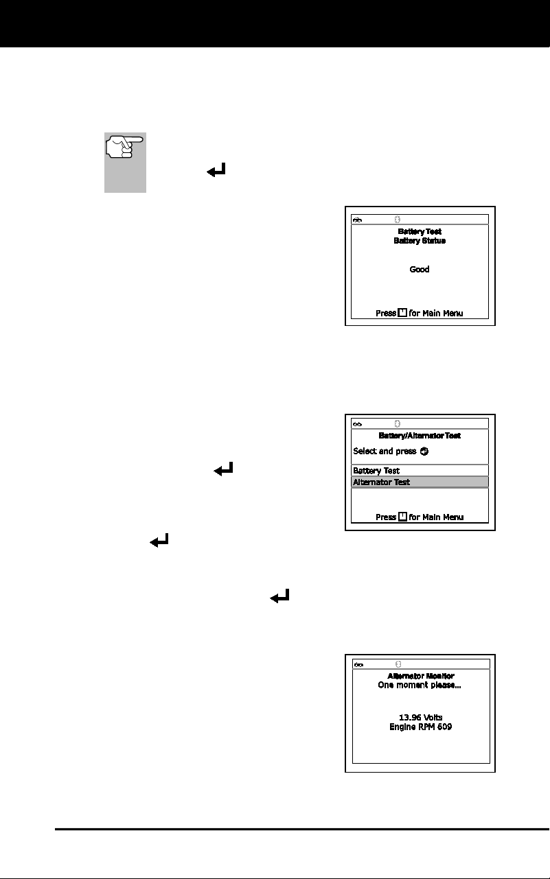
Additional Tests
BATTERY/ALTERNATOR TEST
85
An “instructional” message shows.
8. Start the vehicle’s engine. Allow the engine to run for several
seconds, then turn the engine off. Repeat for a total of three
“start/stop” cycles.
If the Scan Tool did not detect “cranking status” for the
vehicle’s engine, an advisory message shows. Press
ENTER
to repeat the battery check, or, press M to
return to the Main Menu.
9. When the battery check is complete, a
results screen displays the battery
status. The System Status LEDs
provide a PASS/FAIL indication, as
follows:
Green = Good
Yellow = Normal
Red = Warning/Bad
10. Press M to return to the Main Menu.
To perform a charging system check:
1. Press M and release.
The Main Menu displays.
2. Select Battery/Alternator Monitor,
then press ENTER
.
The Battery/Alternator Test Menu
displays.
3. Select Alternator Monitor, then press
ENTER
.
An “instructional” message shows.
4. Start and warm the engine to normal operating temperature. Turn on
the headlights. Press ENTER
to continue.
An “instructional” message shows.
5. Press the accelerator pedal to raise engine speed to 2000 RPM,
and maintain the engine speed.
When engine speed is within the
required range, the alternator test
begins. A progress screen shows.
When the “countdown” timer expires,
an “instructional” message shows.
6. Turn the vehicle’s headlights off, and
return the engine to idle speed.
A “One moment please…” message displays while the test
results are retrieved.
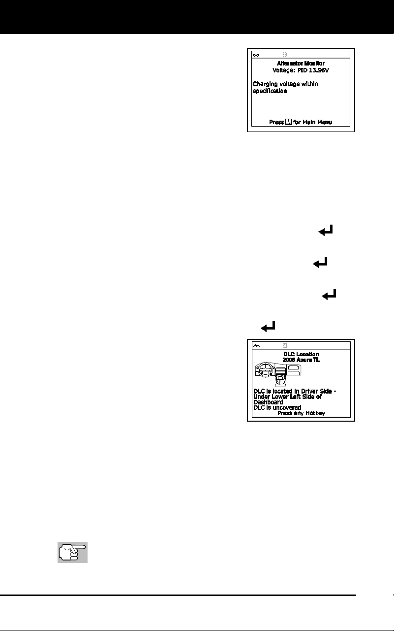
Additional Tests
USING THE DLC LOCATOR - VIEWING VEHICLE INFORMATION
86
7. When the alternator check is complete,
a results screen shows charging system
voltage and indicates whether or not the
charging system is within acceptable
limits. The System Status LEDs provide
a PASS/FAIL indication, as follows:
Green = System within limits
Yellow = Over charging or under
charging
Red = Excessive over charging or under charging
If the alternator voltage is less than 9 V, the red, yellow and
green SYSTEM STATUS LEDs will flash on and off.
8. Press M to return to the Main Menu.
USING THE DLC LOCATOR
1. Select DLC Locator in the Main Menu, then press ENTER .
The Select Vehicle Model Year screen displays.
2. Select the desired vehicle model year, then press ENTER
.
The Select Vehicle Manufacturer screen displays.
3. Select the desired vehicle manufacturer, then press ENTER
.
The Select Vehicle Model screen displays.
4. Select the desired model, then press ENTER
.
The DLC Location screen for the
selected vehicle displays.
The DLC Location screen shows the
selected vehicle make and model, a
description of the DLC location and
whether the DLC is “covered” or
“uncovered,” and includes a picture
of the DLC location.
5. When you have finished viewing the DLC location, press any hotkey
to exit the DLC Locator.
VIEWING VEHICLE INFORMATION
The Vehicle Information function offers three options for retrieving
reference information for the vehicle under test; Vehicle ID, Available
Modules and IPT (In-Use Performance Tracking).
Retrieving Vehicle ID Information
The Vehicle ID function is applicable to model year 2000 and
newer OBD2-compliant vehicles.
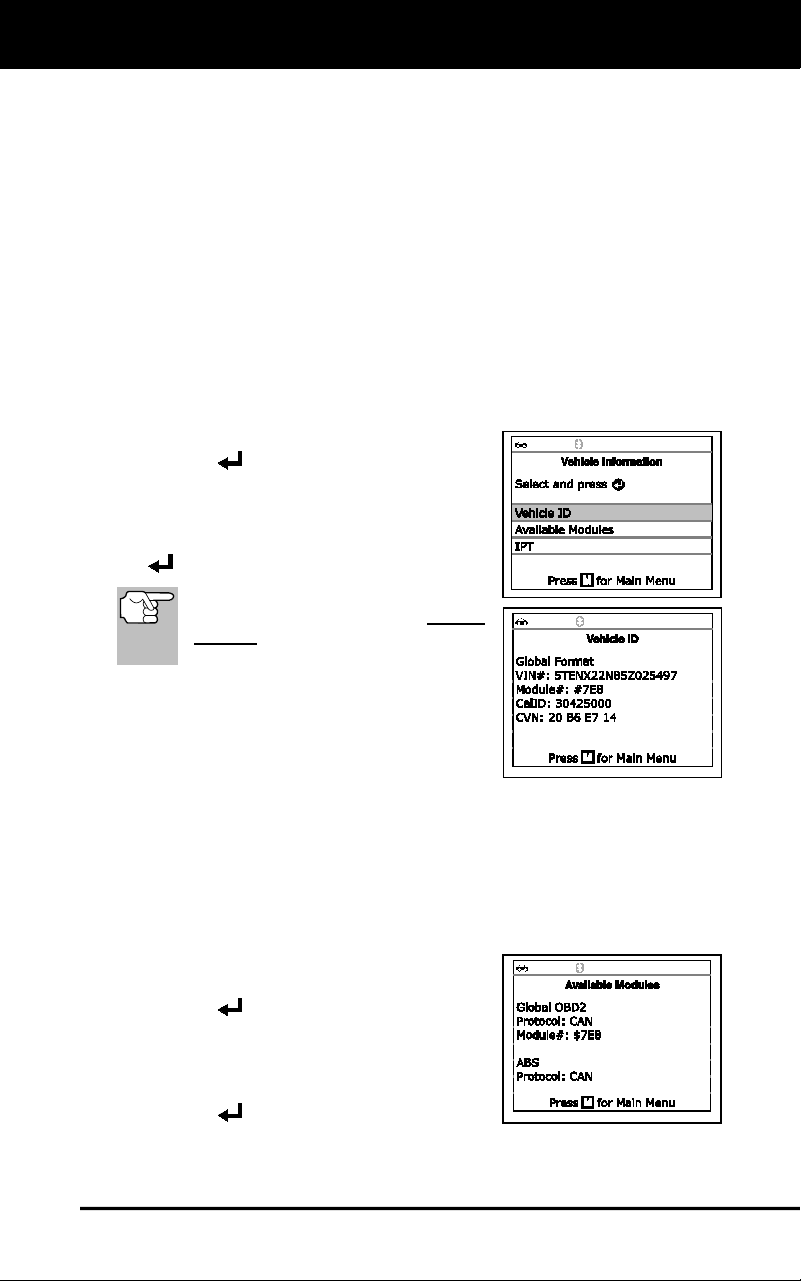
Additional Tests
VIEWING VEHICLE INFORMATION
87
The Scan Tool can retrieve a list of information (provided by the vehicle
manufacturer), unique to the vehicle under test, from the vehicle's on-
board computer. This information may include:
The vehicle's VIN number
The control module identification number
The vehicle's calibration ID(s). These IDs uniquely identify the
software version(s) for the vehicle's control module(s).
The Vehicle's Calibration Verification Number(s) (CVNs) required by
ODB2 regulations. CVNs are used to determine if emission-related
calibrations for the vehicle under test have been changed. One or
more CVNs may be returned by the vehicle's computer.
1. With the Scan Tool in OBD2 mode, press M.
The Main Menu displays.
2. Select Vehicle Information, then press
ENTER
.
The Vehicle Information menu
displays.
3. Select Vehicle ID, then press ENTER
.
The first time the Vehicle ID
function is used, it may take several
minutes to retrieve the information
from the vehicle's computer.
4. When the retrieval process is completed,
the vehicle ID information displays.
5. When you have finished viewing the
retrieved vehicle ID information, press
M
to return to the Main Menu.
Viewing Available Modules
The Scan Tool can retrieve a list of modules supported by the vehicle
under test.
1. With the Scan Tool in OBD2 mode, press M.
The Main Menu displays.
2. Select Vehicle Information, then press
ENTER
.
The Vehicle Information menu
displays.
3. Select Available Modules, then press
ENTER
.
4. When the retrieval process is completed, a complete list of modules
supported by the vehicle under test displays.
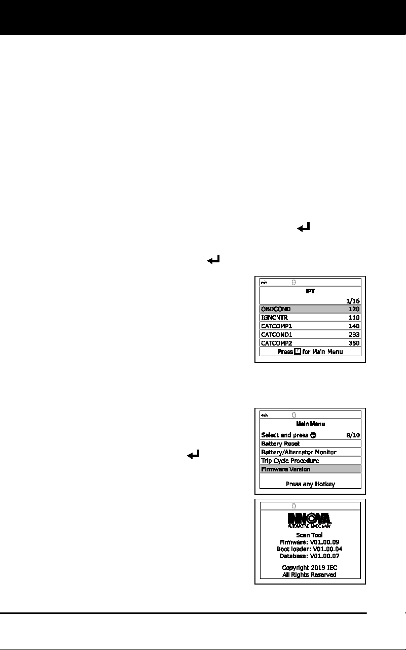
Additional Tests
VIEWING THE FIRMWARE VERSION
88
5. When you have finished viewing the list of available modules, press
M
to return to the Main Menu.
Viewing In-use Performance Tracking (IPT)
The Scan Tool can retrieve In-use Performance Tracking (IPT) statistics
for monitors supported by the vehicle under test. Two values are
returned for each monitor; the number of times that all conditions
necessary for a specific monitor to detect a malfunction have been
encountered (XXXCOND), and the number of times that the vehicle has
been operated under the specific conditions for the monitor (XXXCOMP).
Statistics are also provided for the number of times the vehicle has been
operated in OBD monitoring conditions (OBDCOND), and the number of
times the vehicle’s engine has been started (IGNCNTR).
1. With the Scan Tool in OBD2 mode, press M.
The Main Menu displays.
2. Select Vehicle Information, then press the ENTER
button.
The Vehicle Information menu displays.
3. Select IPT, then press ENTER
.
4. When the retrieval process is completed,
the In-use Performance Tracking
statistics for the vehicle under test
display.
If In-use Performance Tracking is
not available for your vehicle, an
advisory message shows on the
Scan Tool’s display. Press M to
return to the Main Menu.
5. When you have finished viewing the statistics, press M
to return to
the Main Menu.
VIEWING THE FIRMWARE VERSION
1. Select Firmware Version in the Main
Menu, then press ENTER
.
The Firmware Version screen dis-
plays for four seconds.
The screen shows the Scan Tool’s
current firmware version, bootloader
version and database version.
2. The display returns to the Main Menu.
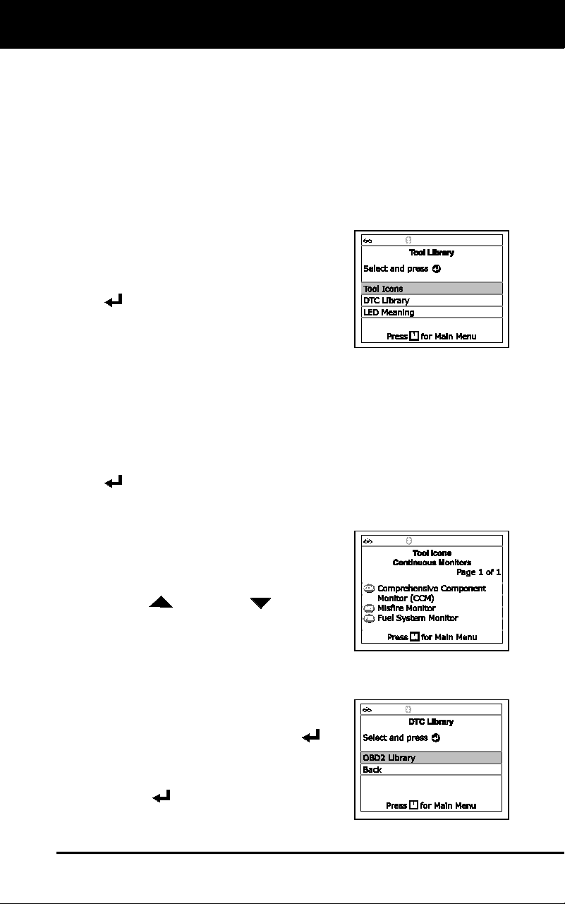
Additional Tests
THE TOOL LIBRARY
89
THE TOOL LIBRARY
The Tool Library contains valuable reference information for the Scan
Tool. The following functions are available:
Tool Icons – Shows the full names for the I/M MONITOR STATUS
icons shown and descriptions of informational icons on the Scan
Tool’s display.
DTC Library – Provides access to libraries of OBD2 DTC definitions.
LED Meaning – Provides descriptions of the meaning of the Scan
Tool SYSTEM STATUS LEDs.
1. While linked to the vehicle, press M.
The Main Menu displays.
2. Select Tool Library, then press ENTER
.
The Tool Library menu displays.
Viewing Tool Icon Descriptions
The I/M MONITOR STATUS icons on the Scan Tool’s LCD display
provide an indication of the “Completed / Not Complete” status for all I/M
Monitors supported by the vehicle under test. The Tool Icons function
displays the full name for each Monitor icon, as well as descriptions of
the meanings of other informational icons shown on the Scan Tool’s
display.
1. From the Tool Library menu, select Tool Icons, then press ENTER
.
The Tool Icons screen displays.
The screen shows a list of the 15
Monitor icons, along with the full
name for each icon, as well as
descriptions of the meanings of
other informational icons. Use the
UP
and DOWN buttons, as
necessary, to scroll the list.
2. When you have finished viewing the
tool icon descriptions, press M
to return
to the Main Menu.
Using the DTC Library
1. From the Tool Library menu, select
DTC Library, then press ENTER
.
The Select Library screen displays.
2. Select OBD2 Library, then press
ENTER
.
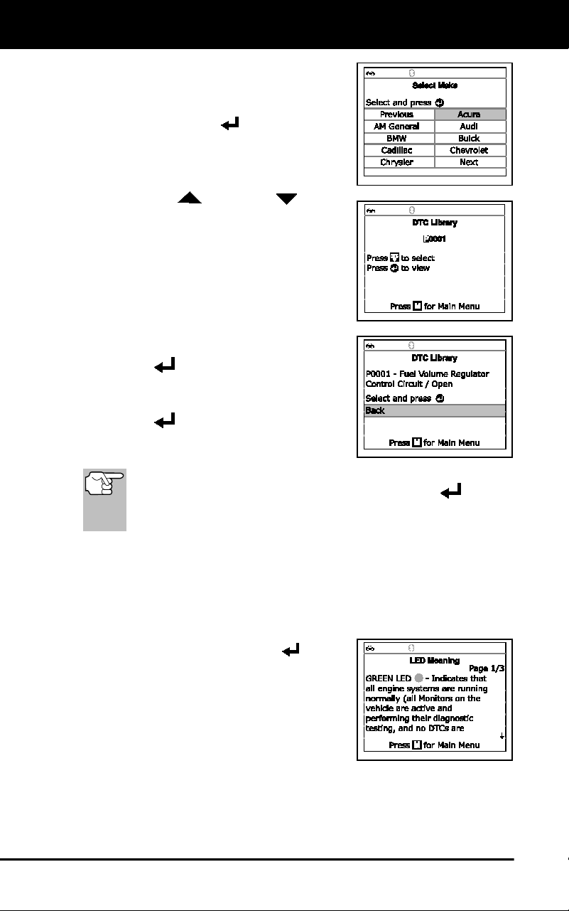
Additional Tests
THE TOOL LIBRARY
90
The Select Manufacturer screen
displays.
3. Select the desired vehicle manufacturer,
then press ENTER
.
The Enter DTC screen displays.
The screen shows the code
“P0001,” with the “P” highlighted.
4. Use the UP
and DOWN buttons,
as necessary, to scroll to the desired
DTC type (P=Powertrain, U=Network,
B=Body, C=Chassis), then press the
DTC/FF button.
The selected character displays solid,
and the next character is highlighted.
5. Select the remaining digits in the DTC
in the same way. When you have
selected all the DTC digits, press
ENTER
to view the DTC definition.
6. When you have finished viewing the DTC
definition, highlight Back, then press
ENTER
to return to the Enter DTC
screen and enter additional DTCs; or,
press M
to return to the Main Menu.
If a definition for the DTC you entered is not available, an advisory
message shows. Highlight Back, then press ENTER
to return
to the Enter DTC screen and enter additional DTCs; or, press M
to
return to the Main Menu.
Viewing LED Meaning
The SYSTEM STATUS LEDs on the Scan Tool provide a visual
indication of the I/M Readiness status of the vehicle under test. The
LED Meaning function provides a description of the meanings of the
green, yellow and red SYSTEM STATUS LEDs.
1. From the Tool Library menu, select LED
Meaning, then press ENTER
.
The LED Meaning screen displays.
The screen provides a description of
the meanings of the green, yellow
and red SYSTEM STATUS LEDs.
2. When you have finished viewing the
LED meanings, press M
to return to the
Main Menu.
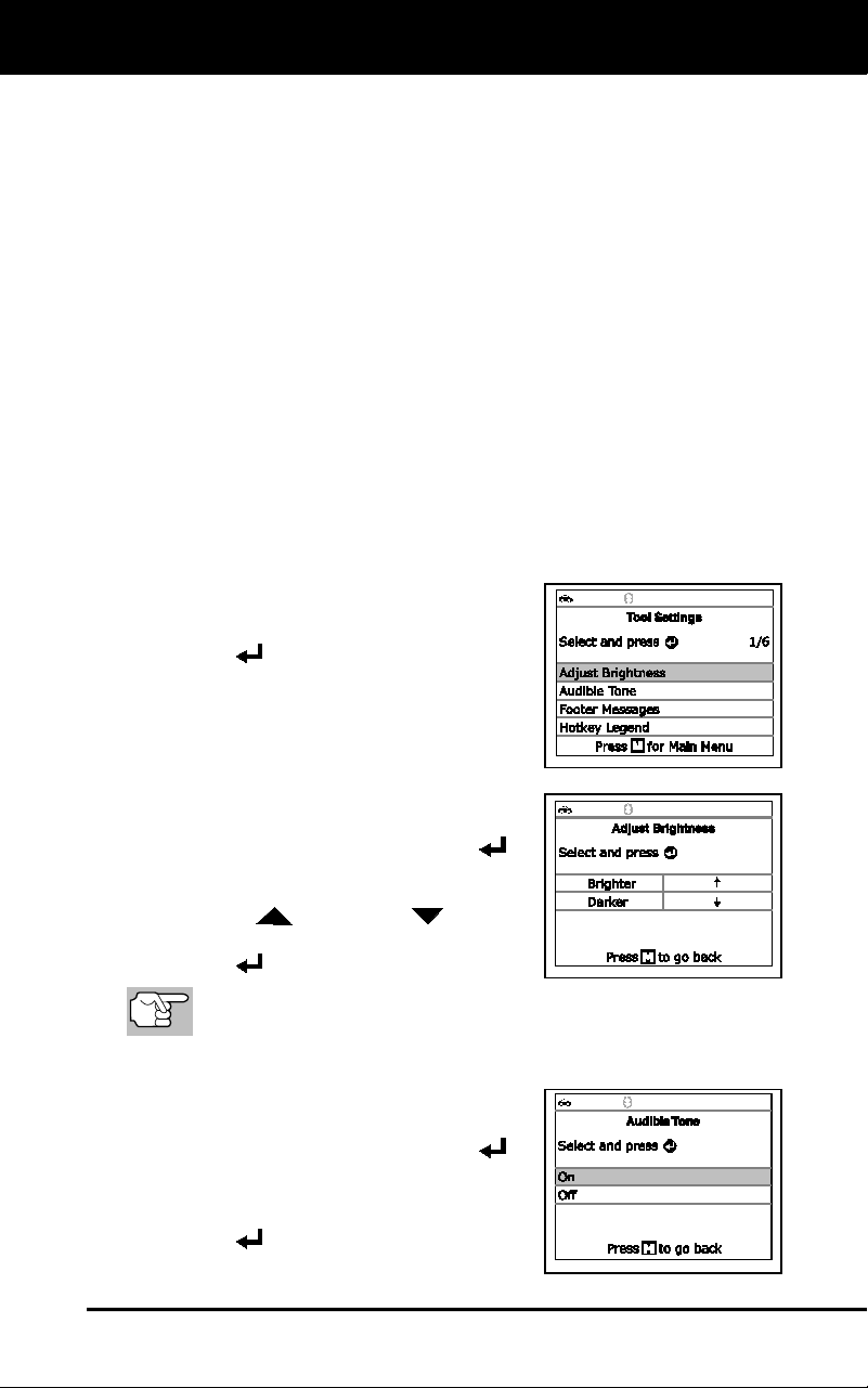
Additional Tests
ADJUSTMENTS AND SETTINGS
91
ADJUSTMENTS AND SETTINGS
The Scan Tool lets you make several adjustments and settings to
configure the Scan Tool to your particular needs. The following
adjustments and settings are available:
Adjust Brightness: Adjusts the brightness of the display screen.
Audible Tone: Turns the Scan Tool’s audible tone “on” and “off.”
When turned “on,” a tone sounds each time a button is pressed.
Footer Messages: Turns the navigational “footers” at the bottom of
most display screens “on” and “off.”
Hotkey Legend: Shows functional descriptions for the Scan Tool’s
hotkeys.
Language Selection: Sets the display language for the Scan Tool
to English, French or Spanish.
Unit of Measurement: Sets the Unit of Measurement for the Scan
Tool’s display to USA or metric.
To enter the Tool Settings mode:
1. While linked to the vehicle, press and release M.
The Main Menu displays.
2. Select Tool Settings, then press
ENTER
.
The Tool Setting menu displays.
3. Make adjustments and settings as
follows.
Adjusting Display Brightness
1. Select Adjust Brightness in the Tool
Settings menu, then press ENTER
.
The Adjust Brightness screen displays.
2. Press UP
and DOWN
to make
the display lighter or darker, then press
ENTER
to save your changes.
To return to the Tool Settings menu without making changes,
press M.
Enabling/Disabling the Audible Tone
1. Select Audible Tone in the Tool
Settings menu, then press ENTER
.
The Audible Tone screen displays.
2. Select On or Off as desired, then press
ENTER
to save your changes.
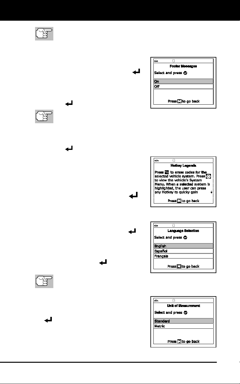
Additional Tests
ADJUSTMENTS AND SETTINGS
92
To return to the Tool Settings menu without making changes,
press M.
Enabling/Disabling Navigational Footers
1. Select Footer Messages in the Tool
Settings menu, then press ENTER
.
The Footer Messages screen dis-
plays.
2. Select On of Off as desired, then press
ENTER
to save your changes.
To return to the Tool Settings menu without making changes,
press M.
Viewing the Hotkey Legend
1. Select Hotkey Legend in the Tool Settings menu, then press
ENTER
.
The Hotkey Legend screen displays.
The screen shows a functional
description of each of the Scan
Tool’s hotkeys.
2. When you have finished viewing the
Hotkey Legend, press ENTER
to
return to the Tool Settings menu.
Selecting the Display Language
1. Select Language Selection in the Tool
Settings menu, then press ENTER
.
The Language Selection screen dis-
plays.
2. Select the desired display language,
then press ENTER
to save your
changes.
To return to the Tool Settings menu without making changes,
press M.
Setting the Unit of Measurement
1. Select Unit of Measurement in the
Tool Settings menu, then press ENTER
.
The Unit of Measurement screen
displays.

Additional Tests
ADJUSTMENTS AND SETTINGS
93
2. Select the desired unit of measurement, then choose Save to save
your changes.
To return to the Tool Settings menu without making changes,
press M.
Exiting the MENU Mode
Press M to return to the Main Menu.
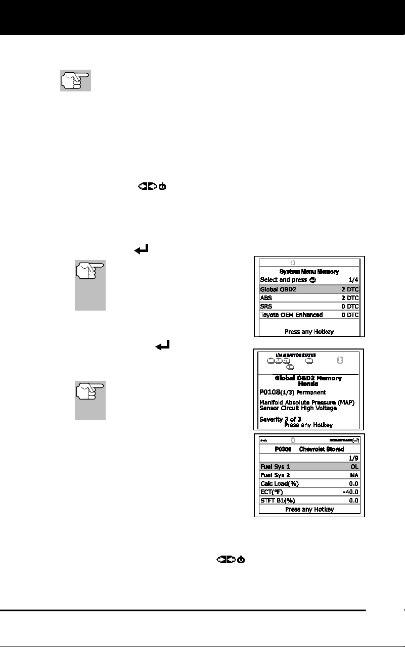
Using Scan Tool Memory
VIEWING DATA IN MEMORY
94
When you retrieve DTCs from a vehicle, the data is saved to the Scan
Tool’s memory.
Each time you retrieve DTCs, existing data in the Scan Tool's
memory is overwritten with the new data.
VIEWING DATA IN MEMORY
When you turn the Scan Tool on while NOT connected to a vehicle, and
data is currently saved in the Scan Tool’s memory, the Scan Tool enters
Memory mode. You can view DTCs and Live Data stored in the Scan
Tool’s memory.
1. With the Scan Tool NOT connected to a vehicle, press and release
POWER/LINK
.
If the Scan Tool’s batteries are low, a warning message displays.
Replace the batteries before continuing.
2. If more than one vehicle is stored in the Scan Tool’s memory, the
Vehicle Selection menu displays. Highlight the desired vehicle, then
press ENTER
.
If there are no vehicles
currently stored in the Scan
Tool, an advisory message
displays. Press the M button to
return to the Main Menu.
The Memory System Menu displays.
3. Highlight the DTCs you wish to view,
then press ENTER
.
The Scan Tool displays the
"priority" DTC.
If there are no DTCs currently
stored in the Scan Tool’s
memory, an advisory message
shows on the display.
Press DTC/FF
to scroll through all
stored DTCs. Press DTC/FF to view
Freeze Frame data for the priority
DTC.
When all DTCs have been displayed
and DTC/FF
is pressed, the Scan
Tool displays the first enhanced DTC
stored in memory. Press DTC/FF
to
scroll through all stored enhanced
DTCs.
4. When you have finished viewing data in the Scan Tool's memory,
press and release POWER/LINK
to turn the Scan Tool off.

Notes
95

Notes
96

Warranty and Servicing
97
LIMITED ONE YEAR WARRANTY
The Manufacturer warrants to the original purchaser that this unit is free
of defects in materials and workmanship under normal use and
maintenance for a period of one (1) year from the date of original
purchase.
If the unit fails within the one (1) year period, it will be repaired or
replaced, at the Manufacturer’s option, at no charge, when returned
prepaid to the Service Center with Proof of Purchase. The sales receipt
may be used for this purpose. Installation labor is not covered under this
warranty. All replacement parts, whether new or remanufactured,
assume as their warranty period only the remaining time of this warranty.
This warranty does not apply to damage caused by improper use,
accident, abuse, improper voltage, service, fire, flood, lightning, or other
acts of God, or if the product was altered or repaired by anyone other
than the Manufacturer’s Service Center.
The Manufacturer, under no circumstances shall be liable for any
consequential damages for breach of any written warranty of this unit.
This warranty gives you specific legal rights, and you may also have
rights, which vary from state to state. This manual is copyrighted with all
rights reserved. No portion of this document may be copied or
reproduced by any means without the express written permission of the
Manufacturer. THIS WARRANTY IS NOT TRANSFERABLE. For
service, send via U.P.S. (if possible) prepaid to Manufacturer. Allow 3-4
weeks for service/repair.
SERVICE PROCEDURES
If you have any questions, require technical support or information on
UPDATES and OPTIONAL ACCESSORIES, please contact your local
store, distributor or the Service Center.
USA & Canada:
(800) 544-4124 (6:00 AM-6:00 PM PST, Monday through Saturday)
All others: (714) 241-6802 (6:00 AM-6:00 PM PST, Monday through
Saturday)
FAX: (714) 241-3979 (24 hr.)
Web: www.innova.com