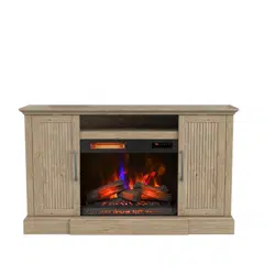
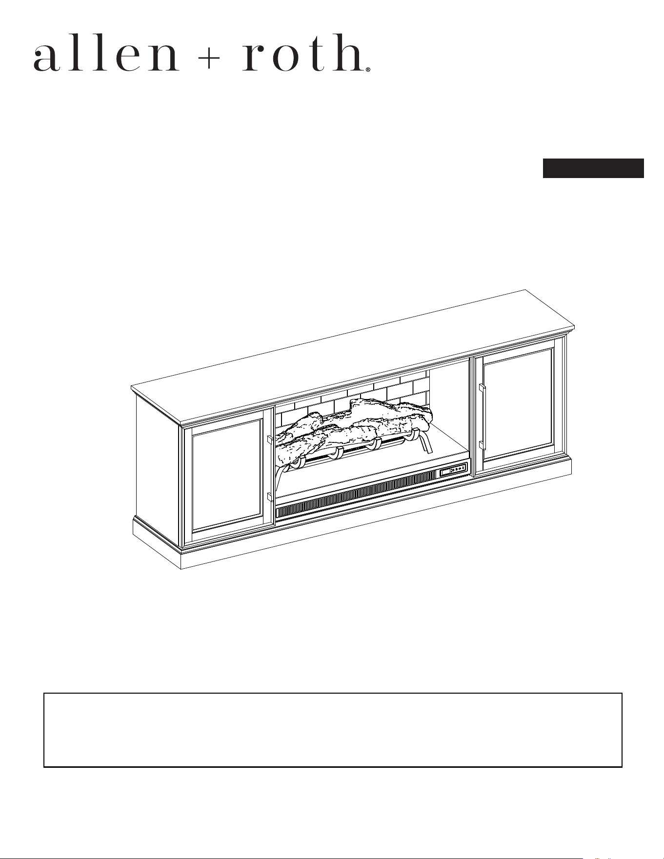
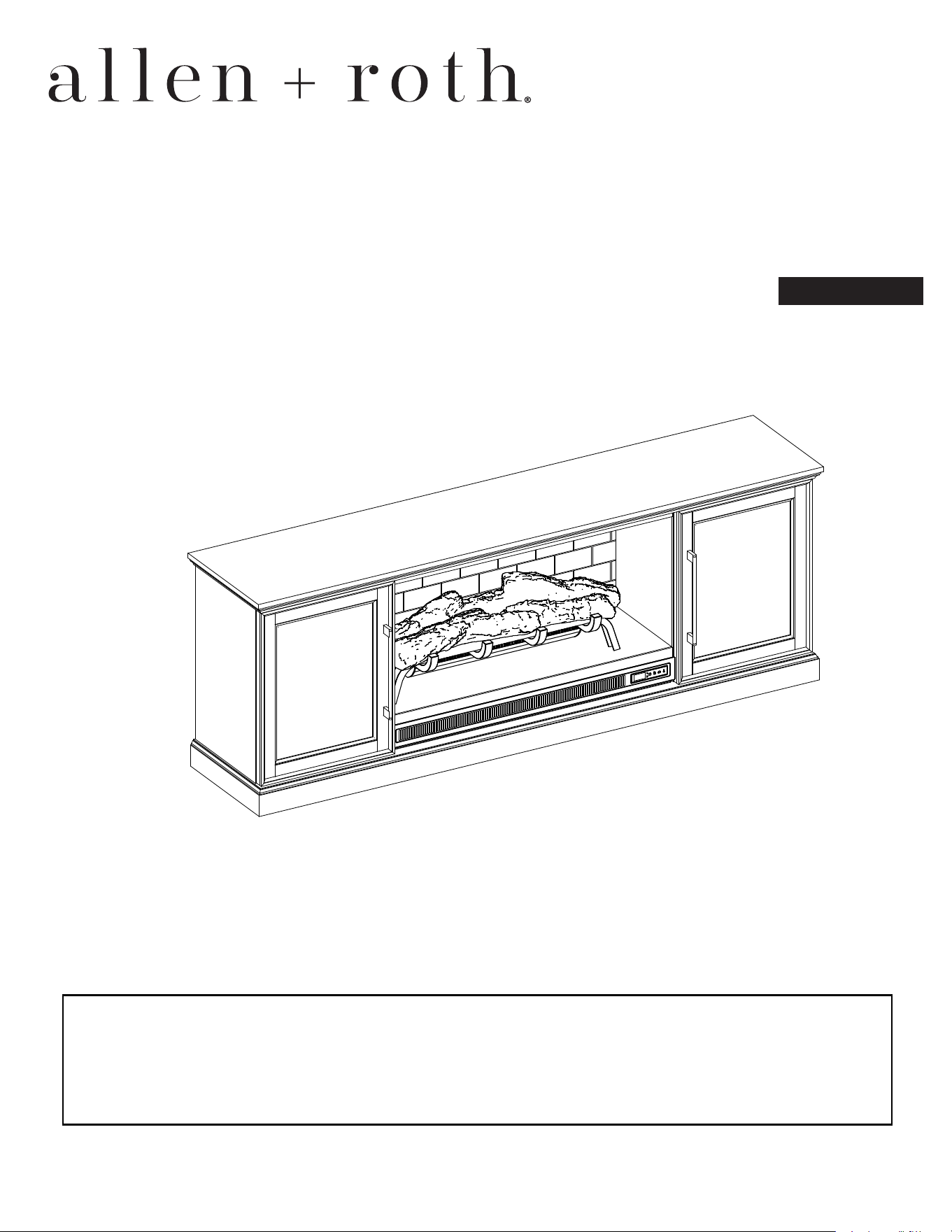
72"LOWPROFILEFIREPLACE
MEDIAMANTEL
,7(06023333
02(/1137MFP-72-36-503
(VSDxROS3
77((,7((
ALLEN+ROTHandlogodesignaretrademarksor
registeredtrademarksofLF,LLC.Allrightsreserved.
HULDOPEHUBBBBBBBBBBBBBBBBBB
UFKDVHDWHBBBBBBBBBBBBBBBBBB
ThankyouforpurchasingthisALLEN+ROTHproduct.
Questions,problemsormissingparts?
Beforereturningcontactuson:
,8a.m.-8p.m.,EST,Monday-Sundayor
866-439-9800
DF25003

2
TABLE OF CONTENTS
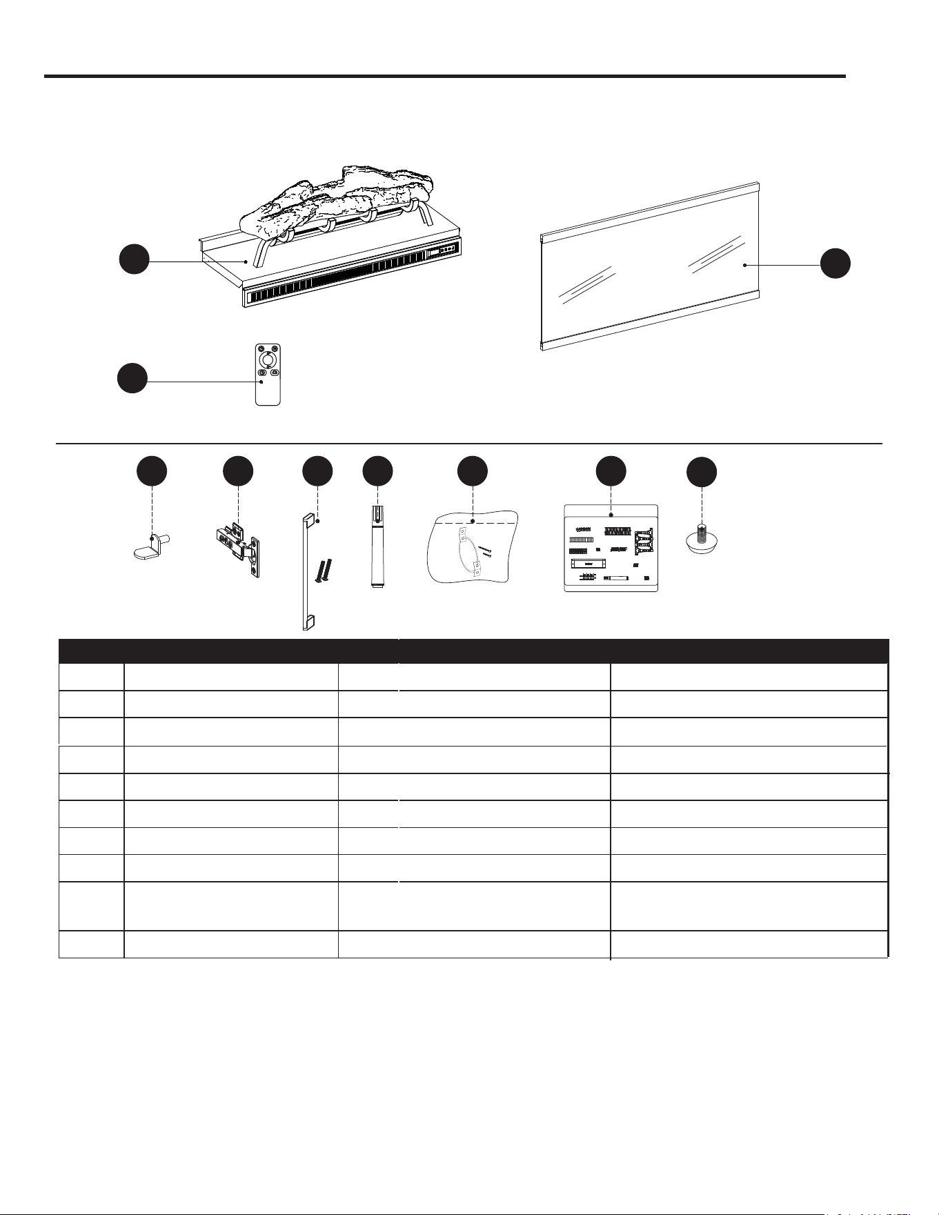
Package Contents ............................................................................................................................... 3
Hardware Contents.............................................................................................................................. 4
Safety Information ............................................................................................................................... 4
Preparation .......................................................................................................................................... 8
Assembly Instructions.......................................................................................................................... 8
Maximum Recommended Weight Loads ........................................................................................... 16
Operating Instructions ....................................................................................................................... 17
Care And Maintenance ...................................................................................................................... 19
Troubleshooting ................................................................................................................................. 20
One-Year Limited Warranty ............................................................................................................... 21
Replacement Parts List ..................................................................................................................... 22
(17(176
A
B
E
C
D
D
E
L
F
F
H
G
H
I
Y
O
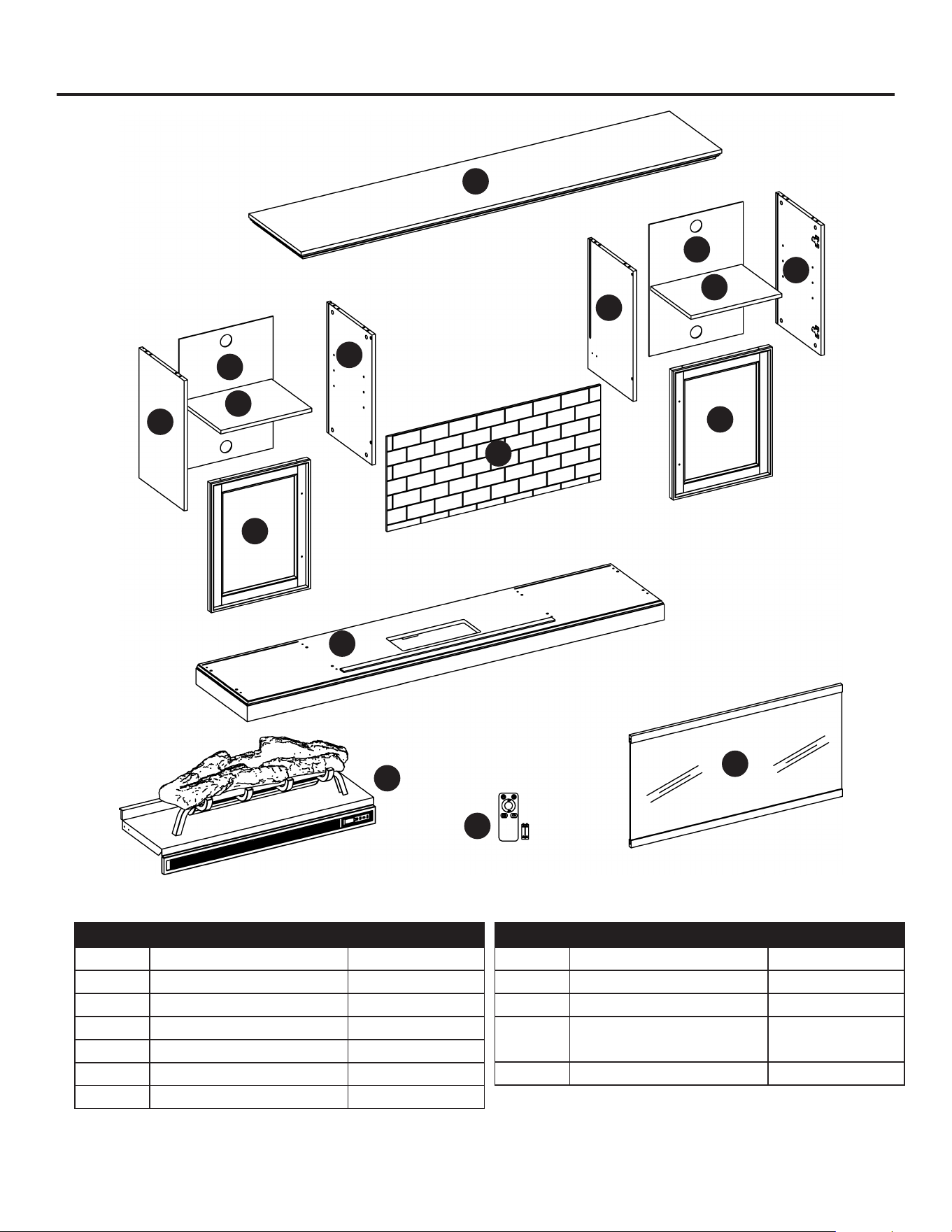
PART DESCRIPTION QUANTITY
A Top 1
B Left Middle Wall 1
C Right Middle Wall 1
D Outer Wall 2
E Shelf 2
F Door 2
G Fireplace Brick Wall 1
PART DESCRIPTION QUANTITY
H Back Panel 2
I Base 1
Y Fireplace 1
O
Remote Control
(Battery)
1
L Fireplace Glass Front 1
:(17(176176:176,(
6)(7,1)7,1
3OHDVHUHDGDQGQGHUVWDQGWKLVHQWLUHPDQDOEHIRUH
DWWHPSWLQJWRDVVHPEOHRSHUDWHRULQVWDOOWKHSURGFW
7KLVHTLSPHQWKDVEHHQWHVWHGDQGIRQGWRFRPSO
ZLWKWKHOLPLWVIRUODVVGLJLWDOGHYLFHVSUVDQWWR
3DUWRIWKH)UOHV7KHVHOLPLWVDUHGHVLJQHG
WRSURYLGHUHDVRQDEOHSURWHFWLRQDJDLQVWKDUPIO
LQWHUIHUHQFHLQDUHVLGHQWLDOLQVWDOODWLRQ7KHHTLSPHQW
JHQHUDWHVVHVDQGFDQUDGLDWHUDGLRIUHTHQF
HQHUJDQGLIQRWLQVWDOOHGDQGVHGLQDFFRUGDQFH
ZLWKWKHLQVWUFWLRQVPDFDVHKDUPIOLQWHUIHUHQFH
WRUDGLRRUWHOHYLVLRQUHFHSWLRQZKLFKFDQEH
GHWHUPLQHGEWUQLQJWKHHTLSPHQWRIIDQGRQ7KH
VHULVHQFRUDJHGWRWUDQGFRUUHFWWKHLQWHUIHUHQFH
ERQHRUPRUHRIWKHIROORZLQJPHDVUHV
5HRULHQWRUUHORFDWHWKHUHFHLYLQJDQWHQQD
,QFUHDVHWKHVHSDUDWLRQEHWZHHQWKHHTLSPHQWDQG
WKHUHFHLYHU
RQQHFWWKHHTLSPHQWLQWRDQRWOHWRQD
FLUFLWGLIIHUHQWIURPWKDWWRZKLFKWKHUHFHLYHULV
FRQQHFWHG
RQVOWWKHGHDOHURUDQHSHULHQFHGUDGLR79
WHFKQLFLDQIRUKHOS
7KLVGHYLFHFRPSOLHVZLWK3DUWRIWKH)UOHV
2SHUDWLRQLVVEMHFWWR
WKHIROORZLQJWZRFRQGLWLRQV
7KLV
GHYLFHPDQRWFDVHKDUPIOLQWHUIHUHQFH
DQG
7KLVGHYLFHPVWDFFHSWDQLQWHUIHUHQFHUHFHLYHG
LQFOGLQJLQWHUIHUHQFHWKDWPDFDVHQGHVLUHG
RSHUDWLRQ
KEEP THESE INSTRUCTIONS FOR FUTURE REFERENCE.
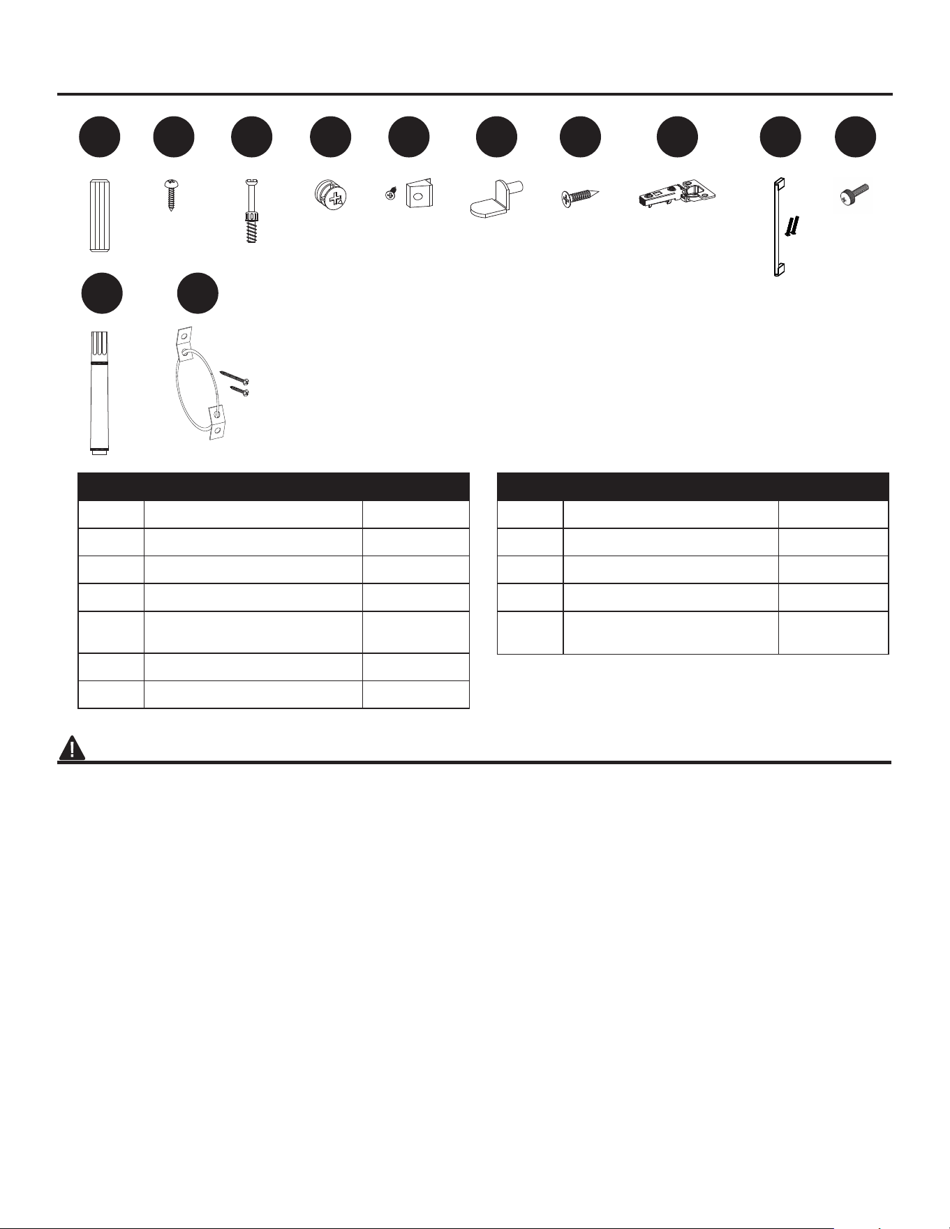
AA BB II JJ
MM NN
CC DD EE FF GG HH
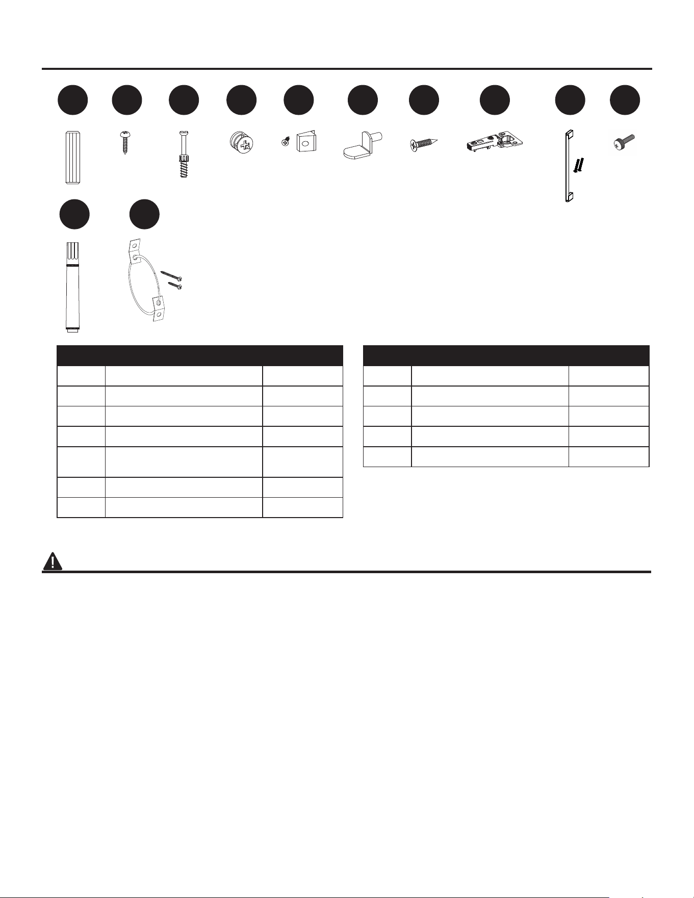
PART DESCRIPTION QUANTITY
AA
Wooden Dowel
16
BB
Screw
4
CC
Connecting Rod
16
DD
Locknut
16
EE
Back panel mounting
hardware with screw
8
FF
Shelf Pin
8
GG
Hinge Screw
8
PART DESCRIPTION QUANTITY
HH
Hinge
4
II
Door Pull
2
JJ
Bolt with Knob
4
MM
Touch-up Pen
1
NN
Tip Restraint Hardware
2
5
SAFETY INFORMATION (CONTINUED)
0RGL¿FDWLRQVQRWDSSURYHGE\WKHSDUW\UHVSRQVLEOH
for compliance could void user’s authority to operate
the equipment.
This Class B digital apparatus complies with Canadian
ICES-003.
IMPORTANT INSTRUCTIONS
When using electrical appliances, basic precautions
VKRXOGDOZD\VEHIROORZHGWRUHGXFHWKHULVNRI¿UH
electric shock and injury to persons, including the
following:
DANGER
• To reduce the risk of electrical shock, ensure the
product is stable and avoid tipping.
• Read all instructions before installing or using this
heater.
• If the information in this manual is not followed
H[DFWO\DQHOHFWULFVKRFNRU¿UHPD\UHVXOWFDXVLQJ
property damage, personal injury or loss of life.
• ALWAYS unplug this appliance/furnishing from the
electrical outlet before cleaning or servicing.
• 7KLVSURGXFWLVLQWHQGHGWR¿WPRVWSODVPDDQG
LCD televisions (up to 72 inches and weighing a
maximum of 95 pounds). Using this item with loads
heavier than the stated maximum can result in
tipping and/or instability, which can result in injury or
even death.
WARNING
• This appliance is hot when in use. To avoid burns,
DO NOT let bare skin touch hot surfaces. Keep
combustible material, such as furniture, pillows,
bedding, papers, clothes and curtains at least 3 feet
from this appliance and keep them away from the
sides and rear.
• Extreme caution is necessary when any heater
is used by or near children or individuals with
GLVDELOLWLHVDQGZKHQHYHUWKH¿UHSODFHLVOHIW
operating and unattended.
• DO NOT run cord under carpeting. DO NOT cover
cord with throw rugs, runners, or similar coverings.
• DO NOT route cord under furniture or appliances.
$UUDQJHFRUGDZD\IURPWUDI¿FDUHDVDQGZKHUHLW
will not be tripped over.
• DO NOT insert or allow foreign objects to enter any
ventilation or exhaust opening as this may cause
DQHOHFWULFVKRFNRU¿UHRUGDPDJHWKHDSSOLDQFH
• This appliance has hot and arcing or sparking parts
inside. DO NOT use it in areas where gasoline,
SDLQWRUÀDPPDEOHYDSRUVRUOLTXLGVDUHXVHGRU
VWRUHG7KLV¿UHSODFHVKRXOGQRWEHXVHGDVD
drying rack for clothing. Christmas stockings or
decorations should not be hung in the area of it.
• Use this appliance only as described in the manual.
Any other use is NOT recommended by the
PDQXIDFWXUHUDQGPD\FDXVH¿UHHOHFWULFVKRFNRU
injury to persons.
• 5HGXFHWKHULVNRIEXUQV¿UHHOHFWULFDOVKRFNRU
injury to persons:
• Unplug from outlet before putting on or taking off
parts.
• Close supervision is necessary when this furnishing
is used by, or near children, invalids, or disabled
persons.
• Use this furnishing only for its intended use
as described in these instructions. DO NOT
use attachments not recommended by the
manufacturer.
• Keep the cord away from heated surfaces.
• Never operate the furnishing with the air openings
blocked. Keep the air openings free of lint, hair, and
other debris.
• Never drop or insert any object into any opening.
• DO NOT operate where aerosol (spray) products
are being used or where oxygen is being
administered.
• To disconnect, turn all controls to the off position,
then remove plug from outlet.
• Each surface intended to support a load shall have
a corresponding statement in the use instructions
specifying the maximum intended load for that
surface in pounds (kilograms).
• Risk of electric shock-connect this furnishing to
a properly grounded outlet only. See Grounding
Instructions.

6
SAFETY INFORMATION (CONTINUED)
• 7RDYRLGHOHFWULFVKRFN¿UHRULQMXU\UHYLHZWKH
DVVHPEO\LQVWUXFWLRQWRFRQ¿UPWKDWWKHDSSURSULDWH
critical components and accessories are being used
with the furnishing.
• Death or serious injury may occur when children
climb on audio and/or video equipment furniture. A
remote control or toys placed on the furnishing may
encourage a child to climb on the furnishing and as
a result the furnishing may tip over on to the child.
• Relocating audio and/or video equipment to
IXUQLWXUHQRWVSHFL¿FDOO\GHVLJQHGWRVXSSRUWDXGLR
and/or video equipment may result in death or
serious injury due to the furnishing collapsing or
overturning onto a child.
CAUTION
• DO NOT operate any heater with a damaged cord
or plug or after the heater malfunctions. DO NOT
operate any heater if it has been dropped or
damaged in any manner. Disconnect power at
service panel and have heater inspected by a
reputable electrician before reusing.
• $Q\UHSDLUVWRWKLV¿UHSODFHVKRXOGEHFDUULHGRXWE\
DTXDOL¿HGVHUYLFHSHUVRQ
• 8QGHUQRFLUFXPVWDQFHVVKRXOGWKLV¿UHSODFHEH
PRGL¿HG3DUWVKDYLQJWREHUHPRYHGIRUVHUYLFLQJ
PXVWEHUHSODFHGSULRUWRRSHUDWLQJWKLV¿UHSODFH
again.
• Household use only.
• DO NOT use outdoors.
• “WARNING – Death or serious injury may occur
when children climb on audio and/or video
equipment furniture. A remote control or toys placed
on the furnishing may encourage a child to climb on
the furnishing and as a result the furnishing may tip
over on to the child”.
• “WARNING – Relocating audio and/or video
HTXLSPHQWWRIXUQLWXUHQRWVSHFL¿FDOO\GHVLJQHGWR
support audio and/or video equipment may result
in death or serious injury due to the furnishing
collapsing or overturning onto a child”.
• This heater is not intended for use in bathrooms,
laundry areas and similar indoor locations. NEVER
place heater where it may fall into a bathtub or other
water container.
• To disconnect this appliance, turn controls to the
OFF position, then remove plug from outlet.
• ONLY connect to properly grounded outlets.
• This appliance, when installed, must be electrically
grounded in accordance with local codes, with the
current CSA C22.1 Canadian Electrical Code or
follow U.S.A. Installations, follow local codes and
the National Electrical Code, ANSI/NFPA N0.70.
• 7RSUHYHQWDSRVVLEOH¿UHDO NOT block air intakes
or exhaust in any manner. DO NOT use on soft
surfaces, like a bed, where opening may become
blocked.
• The heaters MUST NOT be located immediately
below a socket-outlet.
• ALWAYS plug heaters directly into a wall outlet /
receptacle. NEVER use with an extension cord,
re-loadable power tap (outlet / power strip) or a
smart outlet.
• DO NOT slide insert on top of wood to avoid
scratching wood surface.
• DO NOT place any object on top of the insert or
block the air intakes / vents as this can cause the
XQLWWRRYHUKHDWDQGFRXOGFDXVHD¿UH
7
SAFETY INFORMATION (CONTINUED)
Electrical Connection
• A 15-Amp, 120-volt, 60 Hz circuit with a properly
grounded outlet is required. Preferably, the
¿UHSODFHZLOOEHRQDGHGLFDWHGFLUFXLWDVRWKHU
appliances on the same circuit may cause the circuit
breaker to trip or the fuse to blow when the heater
is in operation. The unit comes standard with 6-ft.
three-wire cord, exiting from the rear of the
¿UHSODFHDO NOT exceed the current rating of the
current tap.
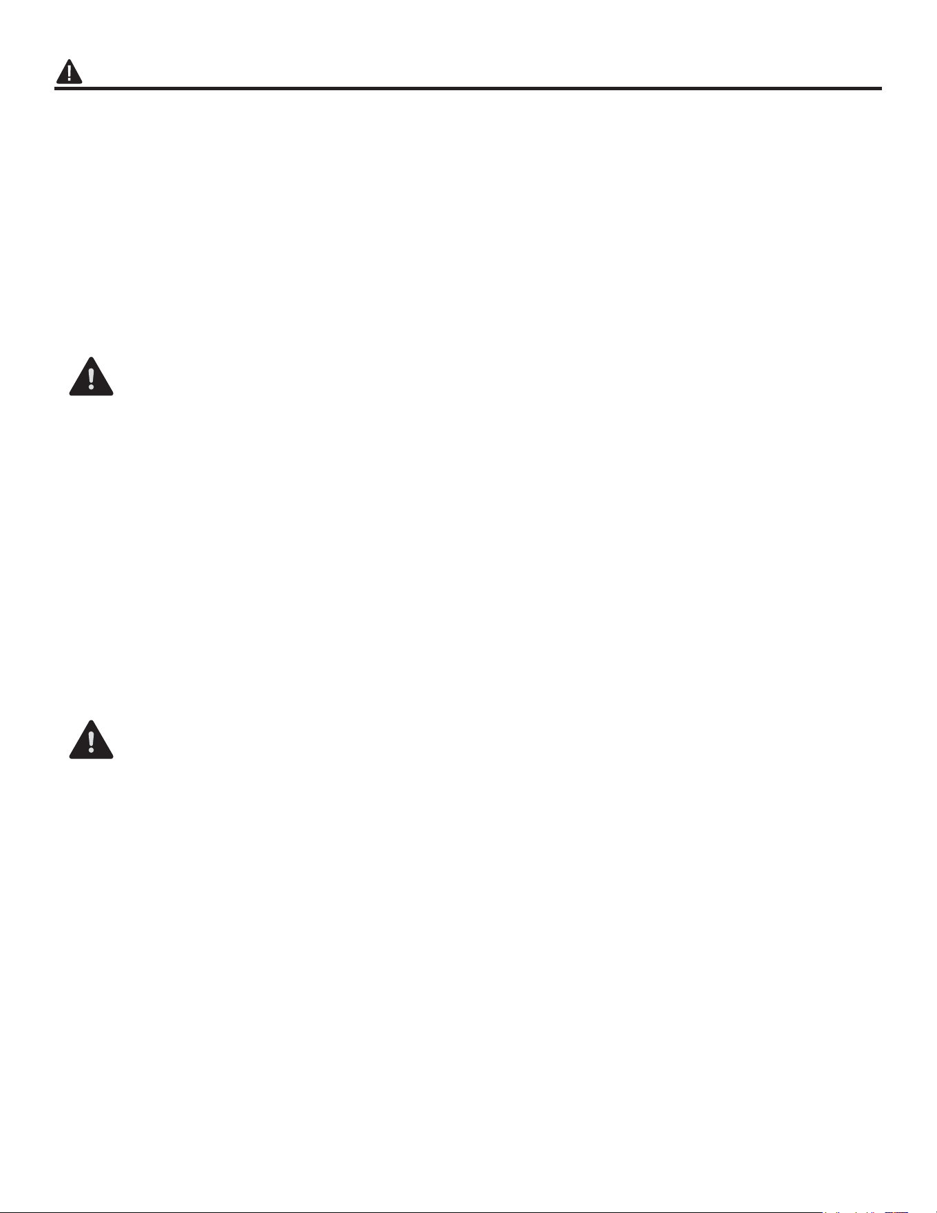
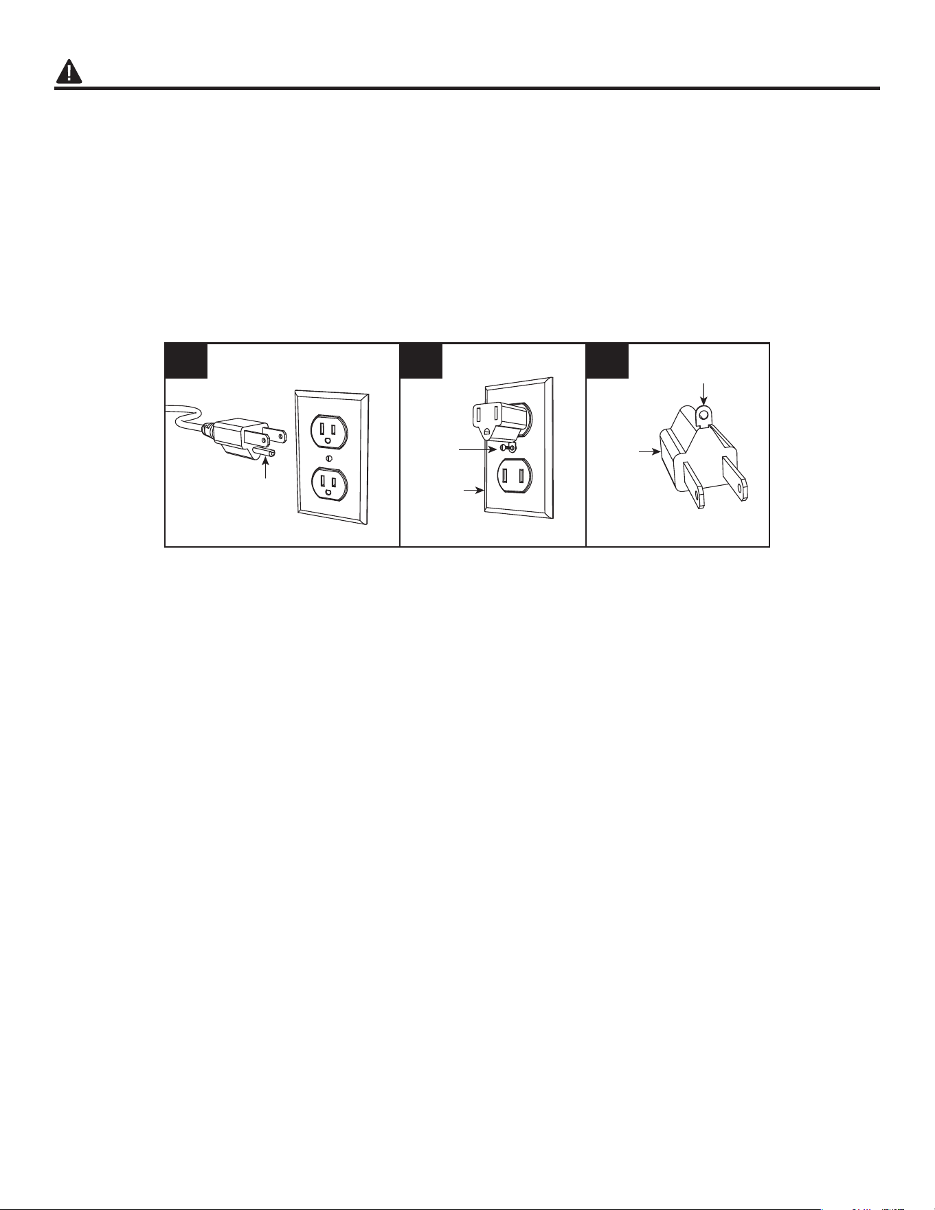
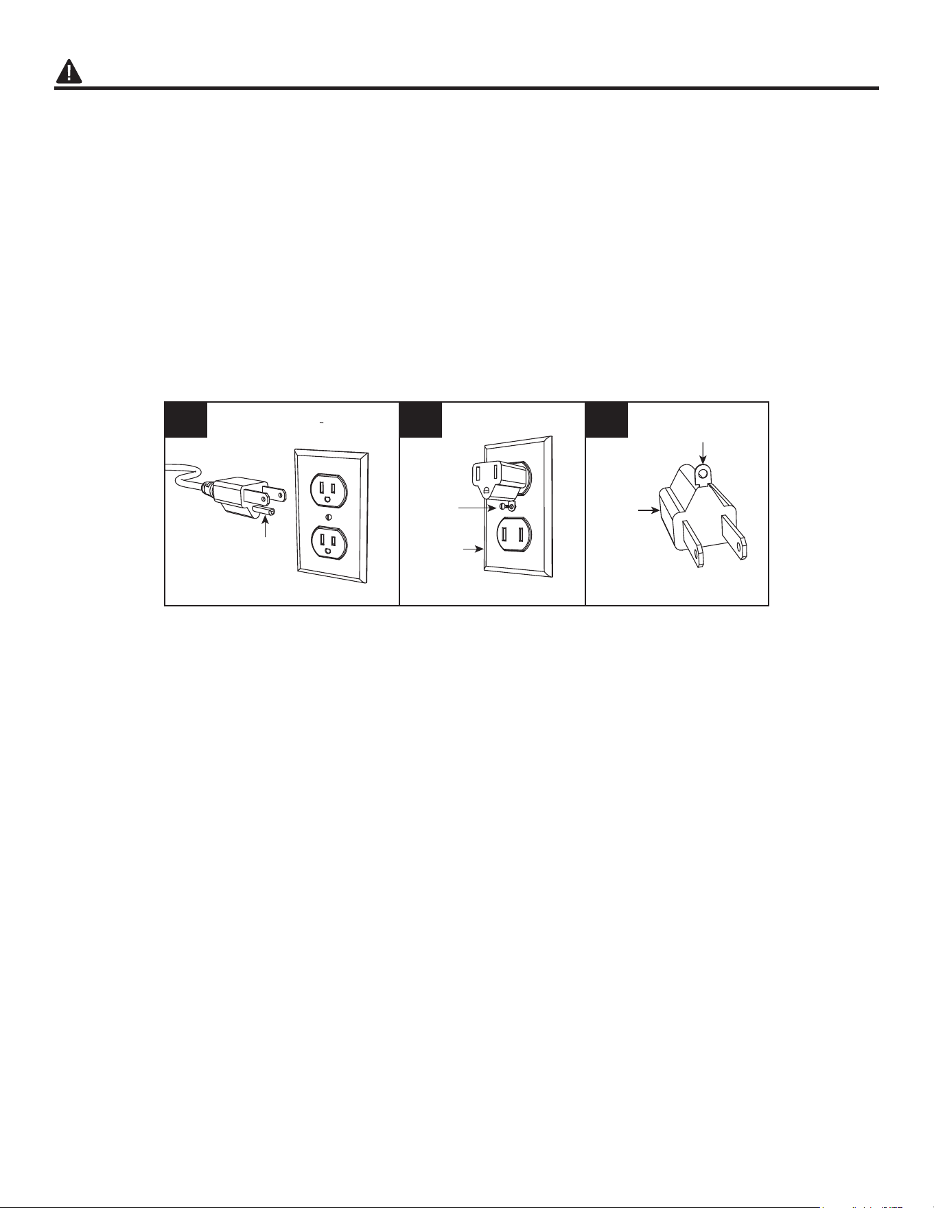
Grounding Instructions
• This heater is for use on 120-volt. The cord has a
plug as shown below. See illustration or grounding
instruction. An adapter as shown at C is available
for connecting three-blade grounding type plugs
to two-slot receptacles. The green grounding plug
extending from the adapter must be connected to
a permanent ground such as a properly grounded
outlet box. The adapter should not be used if a
three-slot grounded receptacle is available.
A B C
Grounding Pin
Grounding Means
Metal
Screw
Cover of
Grounding
Box
Adapter
SAVE THESE INSTRUCTIONS

(7,1
HIRUHEHJLQQLQJDVVHPEORISURGFWPDNHVUHDOOSDUWVDUHSUHVHQWRPSDUHSDUWVZLWK
SDFNDJHFRQWHQWVOLVWDQGKDUGZDUHFRQWHQWVOLVW,IDQSDUWLVPLVVLQJRUGDPDJHGGRQRWDWWHPSW
WRDVVHPEOHWKHSURGFW
(VWLPDWHGVVHPEO7LPH35PLQWHV
7RROVHTXLUHGIRUVVHPEOQRW
LQFOGHG3KLOOLSVVFUHZGULYHU
66(,1677,16
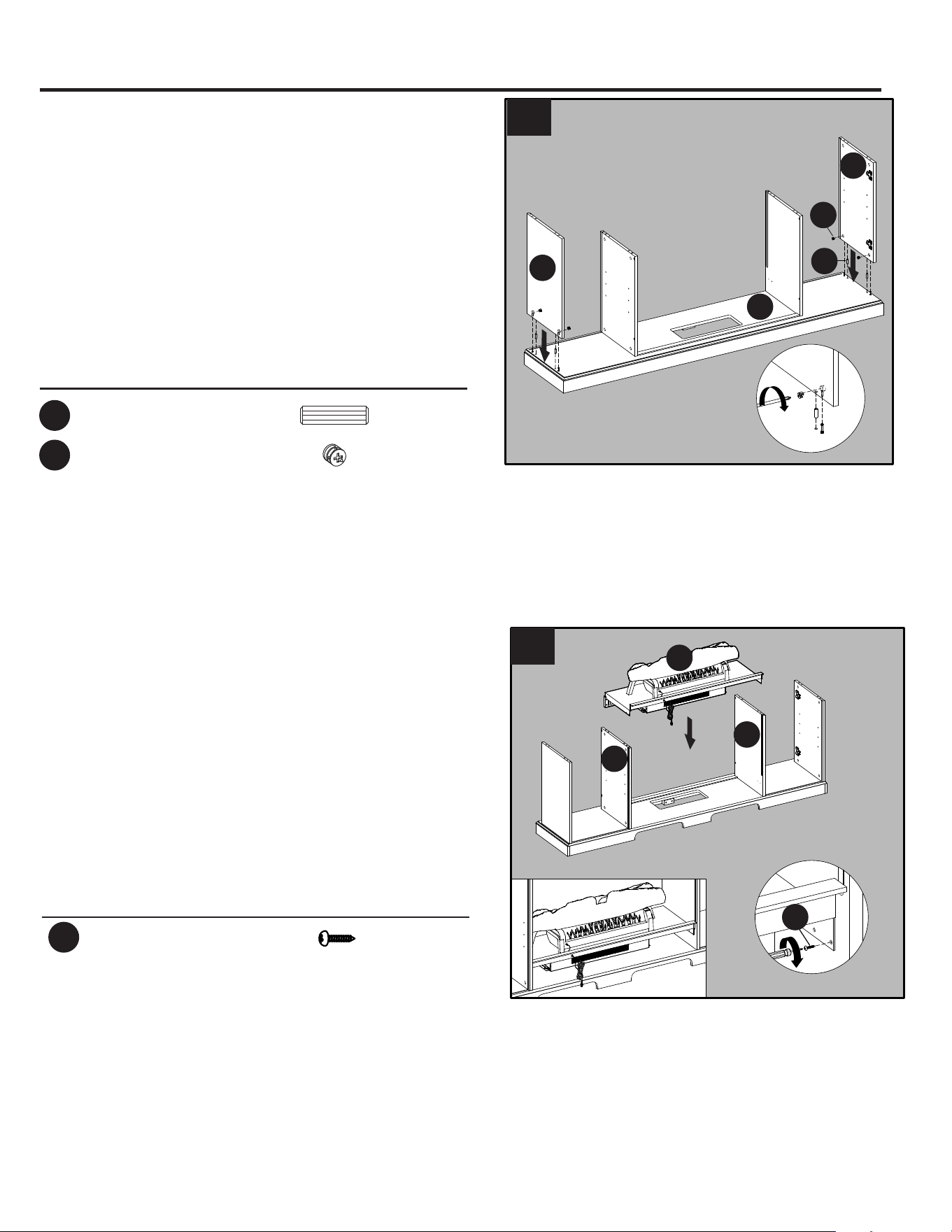
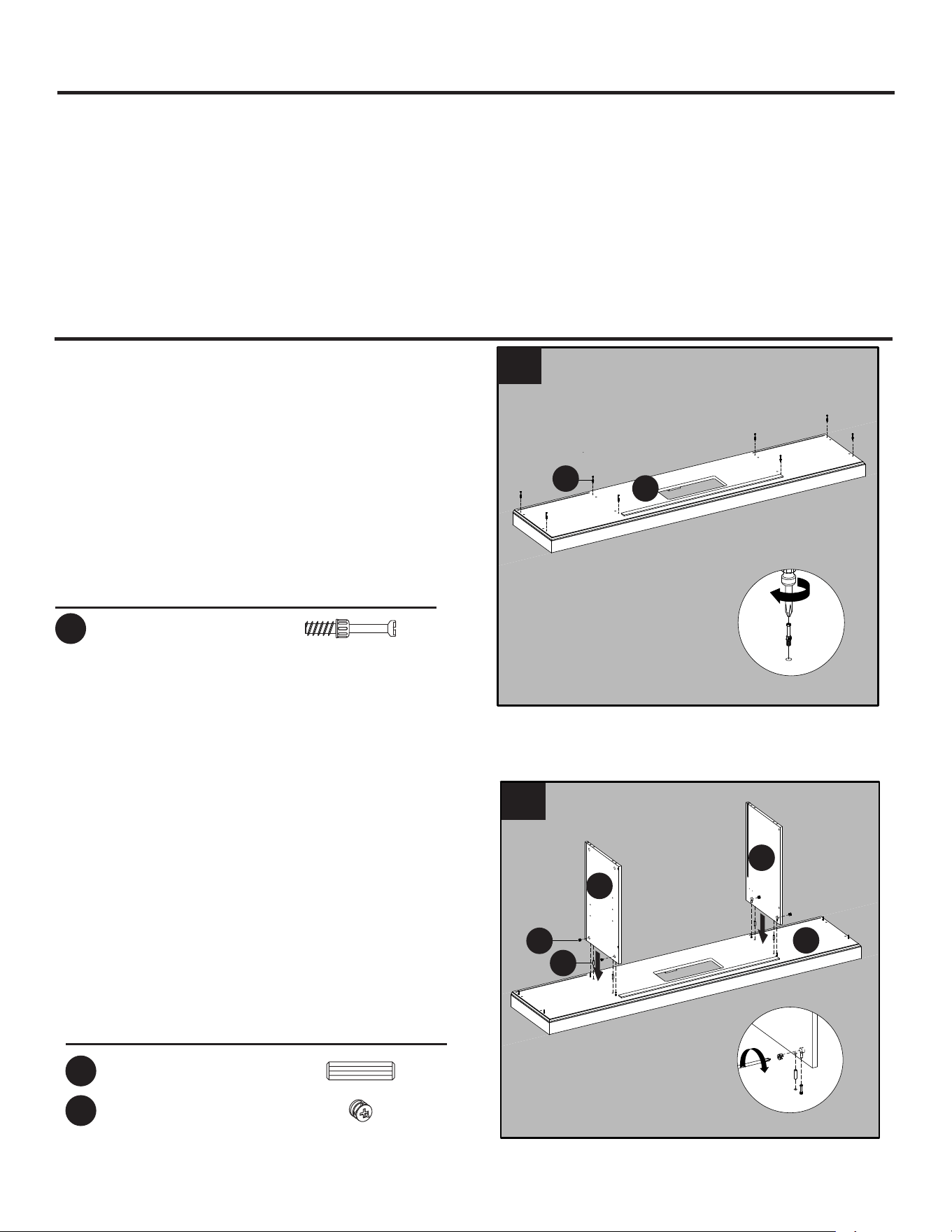
DUGZDUHVHG
Screw eight connecting rods (CC) into the holes
on the top of the base (I).
2
DUGZDUHVHG
2. As shown in the diagram (2), insert four
wooden dowels (AA) into the holes of base (I).
Attach the right middle wall (C) and left middle
wall (B), secure with screwing four locknuts (DD)
Phillips screwdriver.
I
CC
Connecting Rod
x 8
CC
x 4
AA
Wooden Dowel
DD
Locknut
x 4
C
DD
AA
B
I
1
2
9
ASSEMBLY INSTRUCTIONS (CONTINUED)
3. Insert two wooden dowels (AA) into the outer
holes to the right of the base (I). Attach the outer wall
(D), secure with screwing two locknuts (DD) by
Phillips screwdriver.
Repeat for the remaining outer wall (D).
Hardware Used
4. Assemble the fireplace (Y) into center of the left
middle wall (B) and right middle wall (C). Push the
fireplace
to front ward until bottom of the fireplace
stop by black strip line. Screw at back of the
fireplace (Y) into the left middle wall (B) and right
middle wall (C) using four screws (BB). As show in
diagram 4.
Hardware Used
x 4
BB
Screw
DD
2
I
D
AA
D
DD
3
x 4
AA
Wooden Dowel
DD
Locknut
x 4
2
4
C
B
Y
BB
10
ASSEMBLY INSTRUCTIONS (CONTINUED)
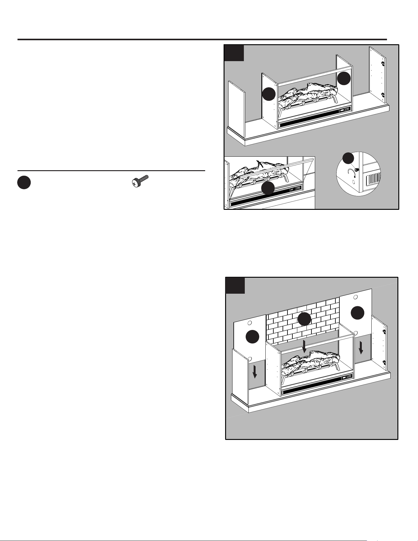
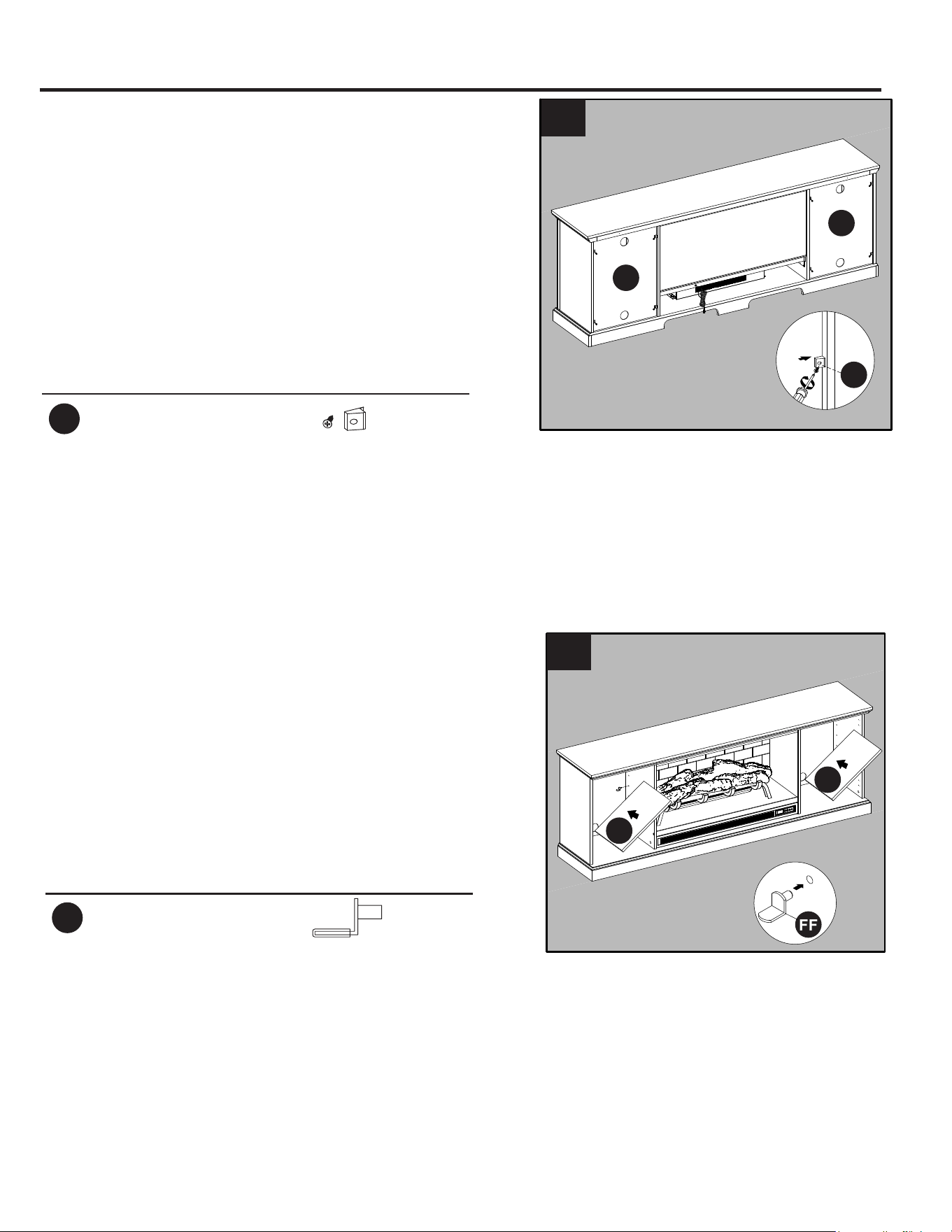
6. As shown in the diagram (6), insert the back
panels (H) into the grooves of the left/right middle
walls (B, C) and outer walls (D).
Next, insert the fireplace brick wall (G) into the
middle of the cabinet by sliding it downward along
the grooves on the left/right middle walls (B, C).
Note: The fireplace brick wall (G) is reversible. You
can choose either the black or brick pattern for your
firebox.
x 4
JJ
Bolt with Knob
2
C
B
L
5
JJ
5. Push the fireplace glass front (L) inward until the
hole on the side of fireplace glass front is adjacent to
the hole on the middle walls. Screw the fireplace
glass front (L) from inside the left and right middle
walls using bolt with bolt with knob (JJ).
DUGZDUHVHG
6
H
H
G
11
ASSEMBLY INSTRUCTIONS (CONTINUED)
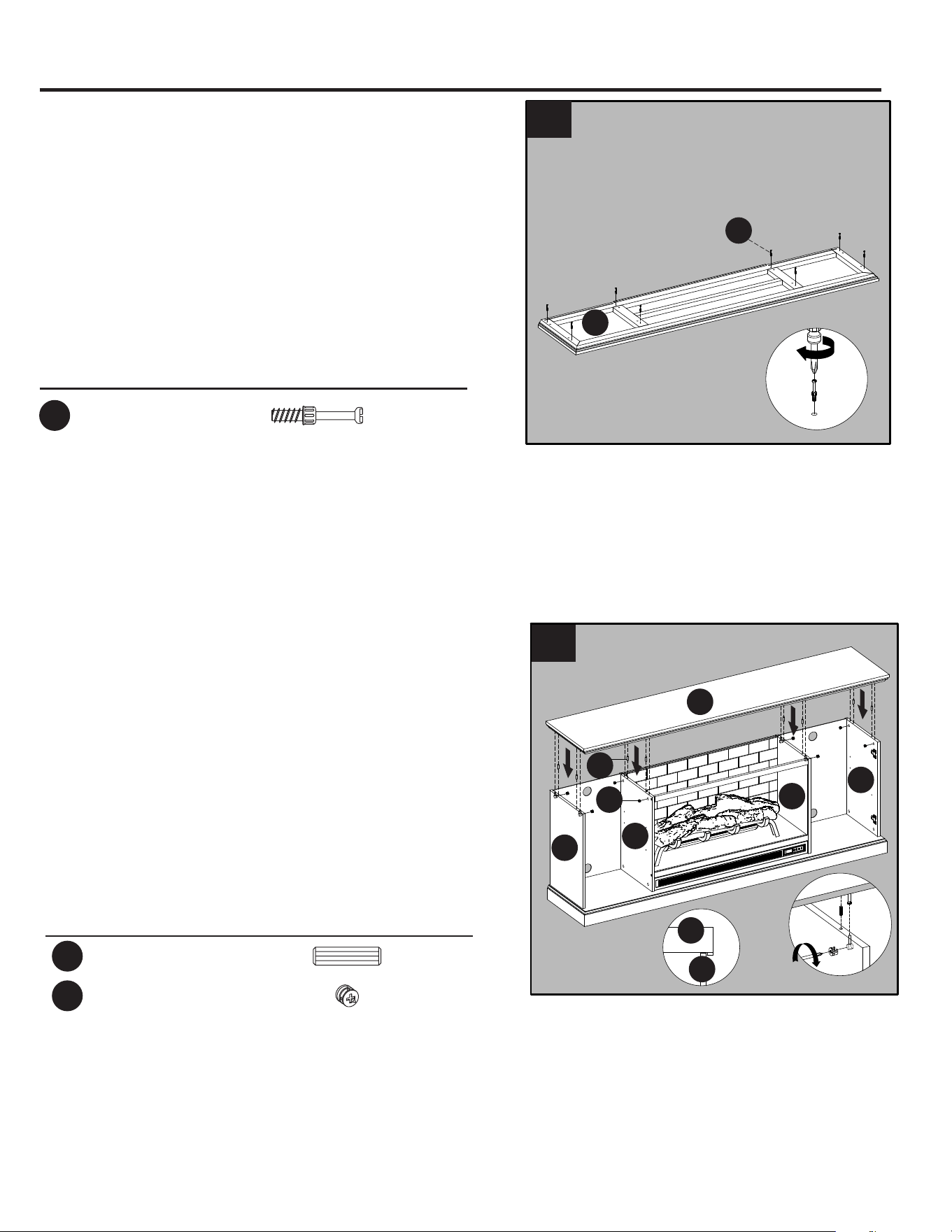
8. Insert wooden dowels (AA) into the top holes of
the outer walls (D) and the partition left/right
middle walls (B, C), align the holes in the top (A)
with the inserted dowels and lower into place.
Secure the top (A) to the outer walls (D) and the
left/right middle walls (B, C) using eight locknuts
(DD).
x 8
CC
Connecting Rod
7. Screw eight connecting rods (CC) into the
designated holes on the back of the top (A).
7
A
CC
2
8
D
AA
A
C
A
B
G
D
DD
Hardware Used
x 8
AA
Wooden Dowel
DD
Locknut
x 8
1
1
1
1
12
ASSEMBLY INSTRUCTIONS (CONTINUED)
10. Insert the shelf pins (FF) at the desired
height, ensuring they are level. Place the shelf
(E) on top of the shelf pins (FF).
Repeat for the remaining shelves (E).
9. Secure the back panels (H) to the product using
the back panel mounting hardware (EE), screwing
the screws by Phillips screwdriver (As shown in
diagram 9).
E
FF
1
2
9
H
H
EE
Hardware Used
EE
Back panel mounting
hardware with screw
x 8
2
2
1
10
E
Hardware Used
FF
Shelf Pin
x 8

13
ASSEMBLY INSTRUCTIONS (CONTINUED)
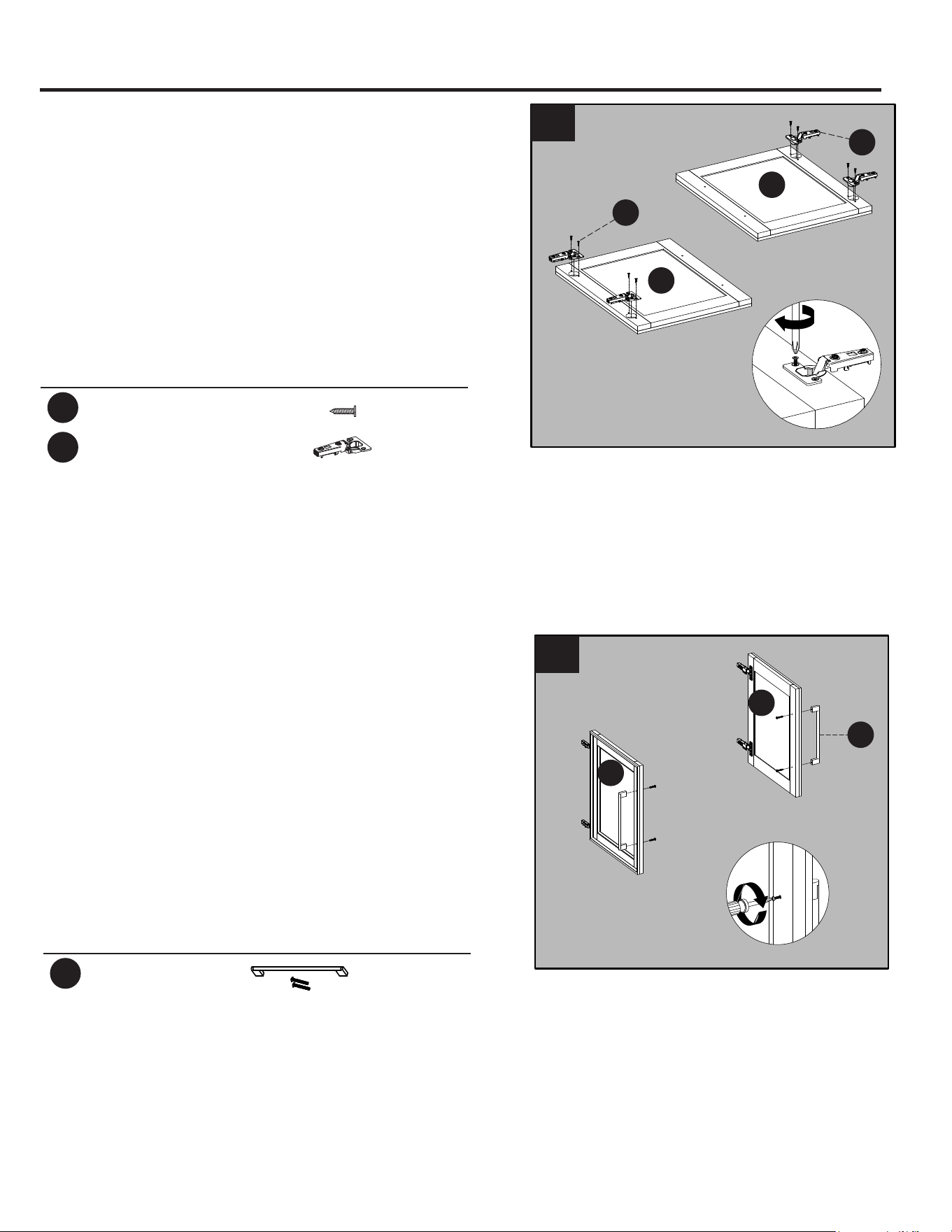
12. Place the door pull (II) into predrilled hole on
the door (F), securing with two door pull screws.
Repeat for the remaining door pull (II).
11. Place the hinges (HH) into predrilled hole
on the door (F), securing with two hinge
screws (GG).
Repeat for the remaining hinges (HH).
11
F
F
GG
HH
Hardware Used
x 8
GG
Hinge Screw
HH
Hinge x 4
12
F
F
II
Hardware Used
II
Door Pull x 2
14
ASSEMBLY INSTRUCTIONS (CONTINUED)
Release lever
I/F
(i)
“J” hook
(ii)
(iii)
I
II
III
13
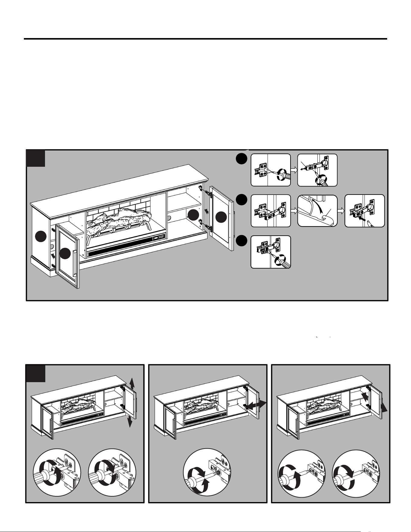
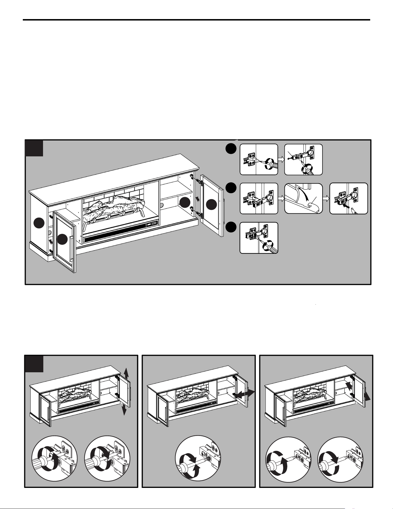
To adjust door up or down, loosen screws (a) on both hinges, adjust door, and retighten screws.
To adjust door left or right, turn screws (b) on both hinges, in and out.
To adjust door in or out, loosen screws (c) on both hinges, adjust door, and retighten screws.
14. If you need to adjust the doors, do so in the following manner.
a
1
a
3
1
1
b
c
1
c
3
2
2
2
2
2
2
13. Install the doors
I. Loosen the screws on the hinge arms and plates pre-attached on the outer walls (D).
II. Pick up door (F) and attach it to outer wall (D) by engaging both door hinges simultaneously.
Please follow the steps below to combine the door hinges together.
i. Extend both hinge arms on the door (F) to open position.
ii. Insert the “J” hooks beneath the hinge arms into the lugs on mounting plates pre-attached on outer wall (D).
iii. Press lightly on the end of both hinge arms to engage the catch.
iv. To remove the hinge arms from the mounting plates, press gently in the release lever on the back of hinge arms.
III. Once assembled, go back and fully tighten all screws.
IV. Repeat the same procedure to attach the door (F) at the opposite side.
V. Open and close the doors to make sure they are aligned and shut correctly. If necessary, adjust the screws for a
good fit.
D
D
F
F
14
15
ASSEMBLY INSTRUCTIONS (CONTINUED)
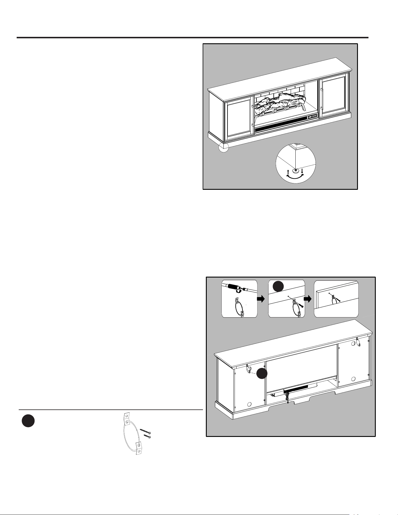
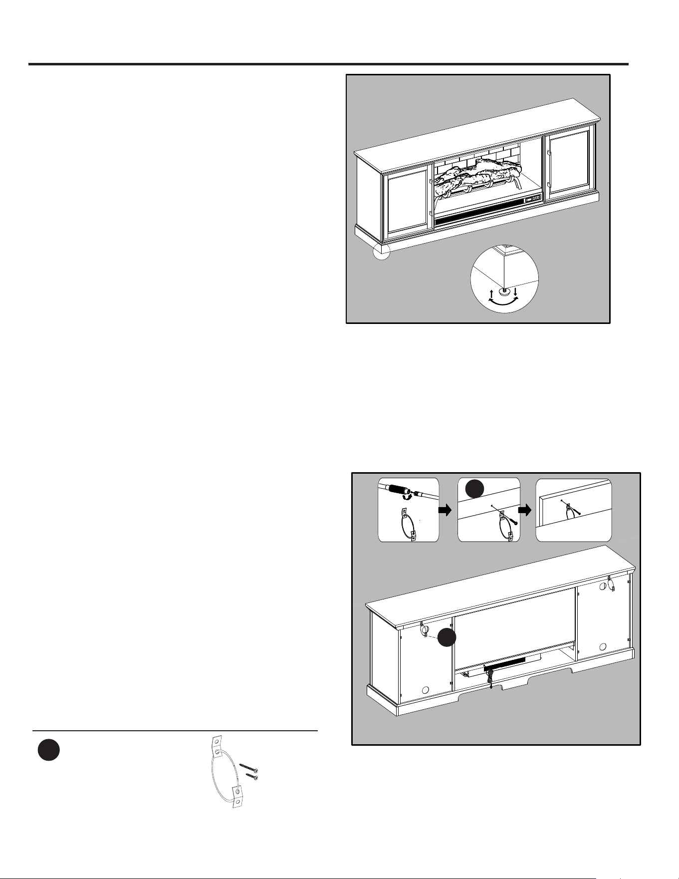
WARNING: You must install the tip restraint
hardware to help prevent any accidents or
damage to the unit. We strongly recommend
attaching the tip restraint hardware to a wall stud
and your unit. For all other wall types, please visit
your local hardware store to obtain the proper
hardware.
Assembly is now complete. With the help of
another person, move the unit to the final desired
position. Once in the final position, you may
attach the tip restraint hardware to the wall. You
may now plug the heater into the power outlet.
NOTE: Use the pre-assembled levelers on the base
of the fireplace to level the unit. Twist the levelers
counterclockwise to increase the height, twist the
clockwise to decrease the height.
Hardware Used
x 2
NN
Tip Restraint
Hardware
Wall Stud
1
2
(i)
3
(ii)
(iii)
A
NN

16
MAXIMUM RECOMMENDED WEIGHT LOADS
CAUTION: This console is intended for use with flat panel TV’s only. Do not exceed the maximum
weights indicated. Use with products heavier than the maximum weights may result in instability causing
possible injury.
FITS UP TO MOST 177.8 cm / 70 in. FLAT PANEL
TVS MAXIMUM LOAD 34.02 kg / 75 lbs
MAXIMUM LOAD 6.8 kg / 15 lbs
MAXIMUM LOAD 6.8 kg / 15 lbs
MAXIMUM LOAD 6.8 kg / 15 lbs
MAXIMUM LOAD 6.8 kg / 15 lbs
17
OPERATING INSTRUCTIONS
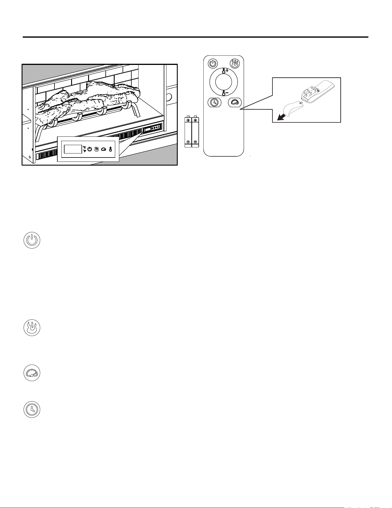
Control Panel Remote Control
Controls and Display
The control panel will display the heater setting when the unit power is turned ON. Whichever control icon
you press will display the current setting of the corresponding function. Press the control icon again to adjust
the setting. Following adjustment of any setting(s), the unit will resume to display the heater setting after 5
seconds.
Power Function
• When the unit is plugged-in but not in use, F or C will illuminate to indicate that it is in stand-by
mode.
• Press the POWER ICON to turn the main power to the unit ON or OFF.
• When the unit is powered ON, the control panel will display the heater setting to indicate the unit
has power.
• Functions stored in memory will resume at the last setting.
• When the unit is powered OFF, the fan will continue to blow for a 40 second cool-down cycle prior
to shutting down (a countdown will be displayed).
Flame Brightness Function
• 3UHVVWKH)/$0(%5,*+71(66,&21WRGLVSOD\WKHFXUUHQWÀDPHEULJKWQHVVVHWWLQJ
• 3UHVVWKH)/$0(%5,*+71(66,&21DJDLQWRVFUROOGRZQWKURXJKWKHÀDPHEULJKWQHVVVHWWLQJV
5, 4, 3, 2, 1, oF (OFF).
Flame Speed Function
• 3UHVVWKH)/$0(63((',&21WRGLVSOD\WKHFXUUHQWÀDPHVSHHGVHWWLQJ
• 3UHVVWKH)/$0(63((',&21DJDLQWRVFUROOGRZQWKURXJKWKHÀDPHVSHHGVHWWLQJV
Sleep Timer Function (Remote Control Only)
• The Sleep TIMER function will set a countdown to shut down the unit’s main power.
• Press the TIMER ICON to display the current Sleep Timer setting.
• Press the TIMER ICON again to scroll through the timer settings, which are: 30 (minutes), 1H, 2H,
3H, 4H, 5H, 6H, 7H, 8H, 9H, oF (OFF).
• When the timer reaches zero, it will turn OFF the main power and will maintain all the settings in
memory.
To use the remote control, first insert two
AAA batteries (included) into the remote
control. Ensure the polarities of the
batteries match the inside of the battery
compartment.
18
OPERATING INSTRUCTIONS (CONTINUED)
Heater Function (Control Panel Only)
• Press the HEATER ICON to display the current heater setting.
• Press the HEATER ICON again to scroll down through the heater settings.
Note: Long-hold the icon to quickly scroll through settings.
• Set the heater to “HI” (High) to have the heater run continually.
• 6HWWKHKHDWHUWR³R)´2))WRXVHWKHÀDPHIXQFWLRQVZLWKRXWKHDW
• This heater has a thermostat sensor to control the ambient temperature in the surrounding area
RIWKH¿UHSODFH7KHKHDWHUZLOOF\FOH21DQG2))WRPDLQWDLQWKHVHOHFWHGWHPSHUDWXUH
7KH
thermostat setting range is 90ºF (32°C) to 65°F (18°C), HI (High) and oF (OFF).
Note: This may not exactly match the room thermostat reading as their sensors are located in
different areas.
• Hold down the FLAME SPEED ICON for 10 seconds to toggle between Fahrenheit and Celsius. “F”
or “C” will be displayed on the control panel (°F/°C can only be toggled from the control panel and
will not work if using the remote control).
• See HEA
TER OVERRIDE section to disengage the heater.
Adjusting the Heater Setting from the Remote Control
• You can scroll upwards or downwards through the heater settings using the remote control for
added convenience.
• Press the PLUS ICON to scroll upwards through the heater settings.
• Press the MINUS ICON to scroll downwards through the heater settings.
HEATER OVERRIDE
The power to the heater can be disengaged to prevent the heater from being accidentally or unintentionally
powered on. This feature is primarily added to help prevent children from powering on the heater when it is not
desired.
Note: The heater override can only be set from the control panel and will not work if using the remote control.
• )LUVWWXUQWKHPDLQSRZHU2))3UHVVWKH32:(5,&21DVWKHKHDWHUVHWWLQJGLVSOD\LVÀDVKLQJSUHVVWKH
POWER ICON again and long-hold 20 seconds. The E3 symbol will display to indicate that the heater is
now disengaged.
• Note: The Flame and Timer functions will operate normally. Only the heater is disengaged.
• Repeat the same process to re-engage the heater function. The E3 symbol will change back to display the
heater setting when the heater is re-engaged.
MEMORY FUNCTION
• This unit has a memory function that allows you to turn off the MAIN POWER and retains all the other
function settings (excluding the SLEEP TIMER function).
19
CARE AND MAINTENANCE
• Make sure the unit is turned OFF, unplugged and the heating elements of heater are cool whenever you are
FOHDQLQJWKHKHDWHURU¿UHSODFH
• Clean the metal trim using a water-dampened soft, clean cloth. DO NOT use brass polish or household
cleaners as these products will damage the metal trim.
• 7KHPRWRUVXVHGRQWKHIDQDQGWKHÀDPHJHQHUDWRUDVVHPEO\DUHSUHOXEULFDWHGIRUH[WHQGHGEHDULQJOLIH
and require no further lubrication. However, periodic cleaning/vacuuming of the fan/heater and air intake/
output vents are recommended.
• When the heater is not in use, the power cord should be stored properly to avoid contact with hot or sharp
objects.
• Any other servicing should be performed by an authorized service representative.
• Tips for using touch-up pen (MM): For scratches, stroke in direction of scratch. For worn areas, stroke in the
direction of wood grain. Rub excess colorant promptly with a soft cloth.
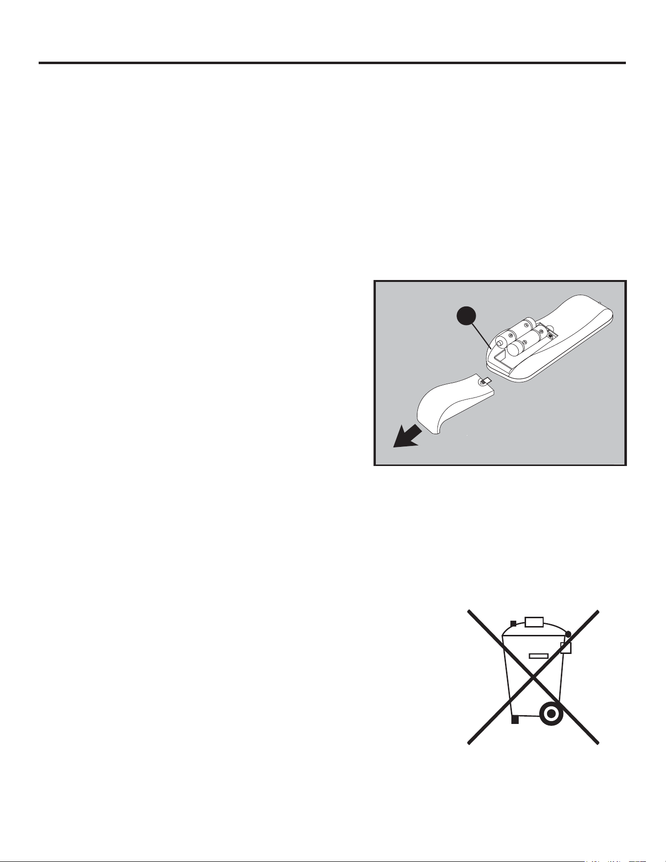
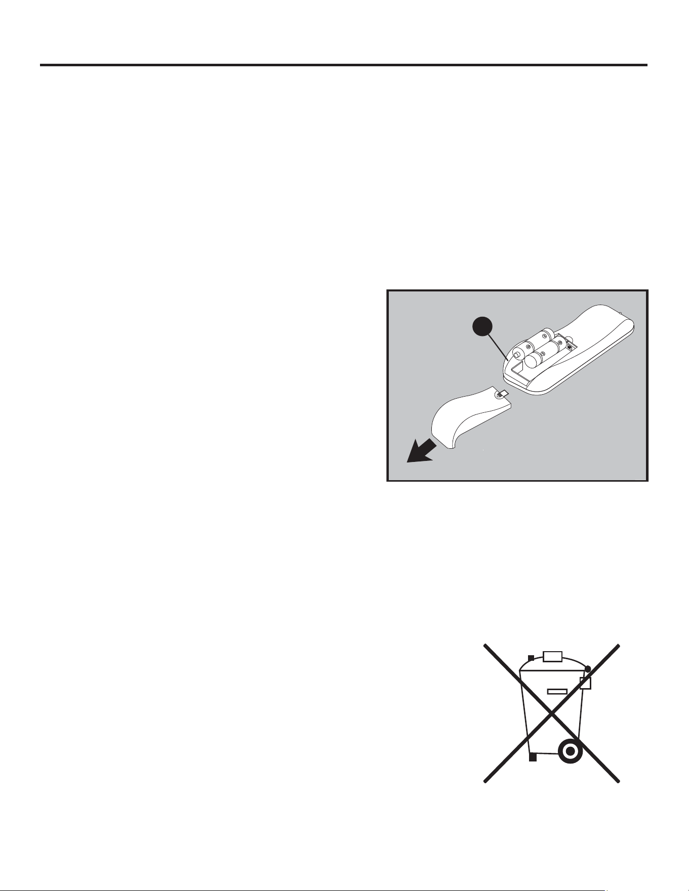
Replacing the Remote-Control Battery
When the remote control (O) stops operating or its range
seems reduced, it is time to replace the battery. Note: The
battery should be removed if the product is to be left unused
for a long time.
1. The battery compartment is located on the back end of the
remote control (O).
Disposal of Used Battery
A battery may contain hazardous substances that could be endangering the environment and human health.
• This symbol marked on the battery and/or packaging indicates that used
battery shall not be treated as municipal waste. Instead, it shall be left at
the appropriate collection point for recycling.
• By ensuring the used battery is disposed of correctly, you will help
prevent potential negative consequences for the environment and human
health. The recycling of materials will help to conserve natural resources.
• 'RQRWGLVSRVHRIEDWWHU\LQ¿UH%DWWHU\PD\H[SORGHRUOHDN
For more information about collection and recycling of used battery, please
contact your local municipality, your waste disposal service or the
point-of-sale where you purchased this battery.
O
and remove old batteries.
Insert 2pcs AAA batteries, ensuring the polarities of the
battery match the inside of the battery compartment.
Re-insert the battery door.
2.
3.
4.
Remove battery cover from the back of remote control (O)
Note:
Do not mix old and new batteries.
Do not mix alkaline, standard (carbon-zinc), or rechargeable (nicad, nimh, etc.) batteries.
Non-rechargeable batteries are not to be recharged. Exhausted batteries are to be removed from the
product.
Harmful if swallowed.
•
•
•
•

20
TROUBLESHOOTING
PROBLEM POSSIBLE CAUSE CORRECTIVE ACTION
Error E1 displayed on
control panel.
The overheat sensor has
been engaged.
Unplug unit, wait 15-20 minutes, then the sensor will reset
itself. Plug the unit back in and turn on the heater. If the
problem persists, call customer service.
Note: The other functions will work normally excluding the
heater.
Error E2 displayed on
control panel.
The thermostat sensor
is broken or not working
correctly.
Unplug unit, wait 15-20 minutes, then the sensor will reset
itself. Plug the unit back in and turn on the heater. If the
problem persists, call customer service.
Note: The other functions will work normally excluding the
heater.
Error E3 displayed on
control panel.
Heater override function is
engaged.
See page 9-Heater Override Section for more details.
No power. The unit does not have
power.
Check that the power cord is securely plugged into a
standard 120
V outlet. Then check to make sure the unit
is powered on.
1RÀDPHHIIHFWEXWWKH
unit is powered on.
7KHÀDPHHIIHFWLV
powered off.
3XVKWKHÀDPHEULJKWQHVVEXWWRQXQWLOGHVLUHGOHYHOLV
achieved.
USB cable. Connect the USB cable into the USB port behind the
Fireplace Grate.
Heater and blower
do not power on but
rest of functions are
working.
Heater setting. Set the heater to "HI" (High) to have the heater run
continually.
Power cord gets warm
to the touch.
Normal operation. This is normal for a heater appliance as it requires more
current to operate. Check the connections of the appliance
FRUGDQGWKHRXWOHW0DNHVXUHWKHSOXJ¿WVWLJKWO\LQWRWKH
outlet. During use, check the plug and outlet frequently to
determine if it is HOT; if so, discontinue use of the appliance
DQGFRQVXOWZLWKDTXDOL¿HGWHFKQLFLDQWRFKHFNRUFKDQJH
the overheating outlet(s).
Remote control does
not work.
Weak or failing battery.
Replace with 2pcs AAA batteries (See page 19 for
more information).
Remote control signal
is weak and only work
sometimes.
Pressing the buttons too
quickly.
Press the buttons slowly and steadily to ensure the
transmitter recognizes the request.
Using the remote control
too far away or at an off
angle.
Move closer to the insert; the remote control will only work
within a distance of 20 feet and 45 degrees to either side
IURPWKHIURQWRIWKH¿UHSODFHLQVHUW
Fan motor continues
to blow after the unit is
powered off.
Normal operation. This is a standard feature; the blower runs for an additional
time to cool off the heater tubes.

21
ONE-YEAR LIMITED WARRANTY
7KHPDQXIDFWXUHUZDUUDQWVWKDW\RXUQHZHOHFWULF¿UHSODFHLVIUHHIURPPDQXIDFWXULQJDQGPDWHULDO
defects for a period of one year from date of purchase, subject to the following conditions and
limitations.
,QVWDOODQGRSHUDWHWKLVHOHFWULF¿UHSODFHLQDFFRUGDQFHZLWKWKHLQVWDOODWLRQDQGRSHUDWLQJLQVWUXFWLRQV
furnished with the product at all times. Any unauthorized repair, alteration, willful abuse, accident, or
misuse of the product shall nullify this warranty.
This warranty is non-transferable, and is made to the original owner, provided that the purchase was
made through an authorized supplier of the product.
The warranty is limited to the repair or replacement of part(s) found to be defective in material or
workmanship, provided that such part(s) have been subjected to normal conditions of use and service,
DIWHUVDLGGHIHFWLVFRQ¿UPHGE\WKHPDQXIDFWXUHU¶VLQVSHFWLRQ
The manufacturer may, at its discretion, fully discharge all obligations with respect to this warranty by
refunding the wholesale price of the defective part(s).
Any installation, labor, construction, transportation, or other related costs/expenses arising from
defective part(s), repair, replacement, or otherwise of same, will not be covered by this warranty, nor
shall the manufacturer assume responsibility for same.
The owner/user assumes all other risks, if any, including the risk of any direct, indirect or consequential
loss or damage arising out of the use, or inability to use the product, except as provided by law.
All other warranties-expressed or implied-with respect to the product, its components and accessories,
or any obligations/liabilities on the part of the manufacturer are hereby expressly excluded.
The manufacturer neither assumes, nor authorizes any third party to assume on its behalf, any other
liabilities with respect to the sale of the product.
The warranties as outlined within this document do not apply to non-accessories used in conjunction
with the installation of this product.
This warranty is void if:
1. 7KH¿UHSODFHLVVXEMHFWHGWRSURORQJHGSHULRGVRIGDPSQHVVRUFRQGHQVDWLRQ
2. Any unauthorized alteration, willful abuse, accident, or misuse of the product.
3. You do not have the original receipt of purchase.
NN OO
QQ
MMIIHHFF
PART #DESCRIPTIONPART
Fireplace <
Remote ControlO
/ )LUHSODFH*ODVV)URQW
PU-[-GLASS FRONT
B1044Shelf PinFF
HingeHH
Door PullII
Touch-up PenMM
ANTI-TIP HARDWARE SETT
ip Restraint HardwareNN
KD Hardware PackOO
PH-0)3
HARDWARE PACK
T-1007LevelerQQ
Printed in Vietnam
PU17-1317FM-005
REPLACEMENT PARTS LIST
O
L
0%+$1'/(
0
6.','
5&+((/
COVERED UNDER WARRANTY
<HV
)RUUHSODFHPHQWSDUWVFDOORXUFXVWRPHUVHUYLFHGHSDUWPHQWDW866-439-9800DPSP
(670RQGD\6XQGD\<RXFRXOGDOVRFRQWDFWXVDW[email protected].
<HV
<HV
<HV
<HV
<HV
<HV
<HV
<HV
<HV
Y
23
REPISA PARA SISTEMA DE
AUDIO Y TV PARA CHIMENEA
DE PERFIL BAJO DE 182.88 CM
ARTÍCULO #6023333
MODELO #1137MFP-72-36-503
(VSDxROS3
ADJUNTE SU RECIBO AQUÍ
ALLEN + ROTH y el diseño del logotipo son marcas
comerciales o marcas registradas de LF, LLC.
Todos los derechos reservados.
Número de serieBBBBBBBBBBBBBBBBBB
Fecha de compraBBBBBBBBBBBBBBBBBB
Gracias por comprar este producto ALLEN + ROTH.
¿Tiene preguntas, problemas o piezas faltantes?
Antes de volver a la tienda, póngase en contacto con nosotros al:
866-439-9800, de lunes a domingo, de 8 a.m. a 8 p.m., hora estándar del Este, o escriba a
DF25003

24
ÍNDICE
Contenido del paquete....................................................................................................................... 25
Aditamentos....................................................................................................................................... 26
Información de seguridad .................................................................................................................. 27
Preparación ....................................................................................................................................... 30
Instrucciones de ensamblaje............................................................................................................. 30
Cargas máximas de peso recomendadas ........................................................................................ 38
Instrucciones de funcionamiento ....................................................................................................... 39
Cuidado y mantenimiento ................................................................................................................... 41
Solución de problemas ....................................................................................................................... 42
Garantía limitada de un año ............................................................................................................... 43
Lista de piezas de repuesto .............................................................................................................. 44

25
CONTENIDO DEL PAQUETE
A
B
E
C
D
D
E
L
F
F
H
G
H
I
Y
O
PIEZA DESCRIPCIÓN CANTIDAD
A Parte superior 1
B Pared central izquierda 1
C Pared central derecha 1
D Pared exterior 2
E Estante 2
F Puerta 2
G
Pared de ladrillos de
la chimenea
1
PIEZA DESCRIPCIÓN CANTIDAD
H Panel posterior 2
I Base 1
Y Chimenea 1
O
Control remoto
(Batería)
1
L
Frente de vidrio de
la chimenea
1
26
ADITAMENTOS(NO SE MUESTRAN EN TAMAÑO REAL)
INFORMACIÓN DE SEGURIDAD
Lea y comprenda completamente este manual antes
de intentar ensamblar, usar o instalar el producto.
Este equipo se probó y se verificó que cumple con los
límites para un dispositivo digital de clase B, conforme
a la sección 15 de las reglas de la FCC. Estos límites
están diseñados para proporcionar protección
razonable contra interferencias perjudiciales en una
instalación residencial. El equipo genera, utiliza y
puede irradiar energía de radiofrecuencia y, si no se
instala y usa de acuerdo con las instrucciones, puede
causar interferencia perjudicial a las comunicaciones
de radio o televisión, la que se puede determinar al
encender y apagar el equipo. Se insta al usuario a
intentar corregir la interferencia con una o más de las
siguientes medidas:
Reorientar o reubicar la antena de recepción.
Aumentar la separación entre el equipo y el
recibidor.
Conectar el equipo a un tomacorriente de un circuito
distinto al que usa el recibidor.
Solicitar ayuda al distribuidor o a un técnico con
experiencia en radio o TV.
Este dispositivo cumple con la Parte 15 de las normas
de la FCC.
El funcionamiento está sujeto a las siguientes dos
condiciones:
Este dispositivo no debe causar interferencia
Este dispositivo deberá aceptar cualquier
interferencia recibida, incluyendo la interferencia
que pudiese causar la operación no deseada.
GUARDE ESTAS INSTRUCCIONES PARA REFERENCIA FUTURA.
AA BB II JJ
MM NN
CC DD EE FF GG HH
PIEZA DESCRIPCIÓN CANTIDAD
AA
Espiga de madera
16
BB
Tornillo
4
CC
Varilla de conexión
16
DD
Contratuerca
16
EE
Aditamentos de montaje del
panel posterior con tornillo
8
FF
Soporte para estante
8
GG
Tornillo para bisagra
8
PIEZA DESCRIPCIÓN CANTIDAD
HH
Bisagra
4
II
Tirador de puerta
2
JJ
Perno con perilla
4
MM
Aplicador de retoque
1
NN
Aditamento de contención
antivuelcos
2
perjudicial y
27
INFORMACIÓN DE SEGURIDAD (CONTINUACIÓN)
Las modificaciones que no estén aprobadas por la
parte responsable del cumplimiento podrían anular la
autorización del usuario para utilizar el equipo.
Este aparato digital clase B cumple con el ICES-003
de Canadá.
INSTRUCCIONES IMPORTANTES
Cuando use electrodomésticos, siempre tome
medidas de precaución básicas para reducir el riesgo
de incendios, descargas eléctricas y lesiones a
personas, incluidas las siguientes:
PELIGRO
• Para reducir el riesgo de descarga eléctrica,
asegúrese de que el producto esté estable y evite
que se vuelque.
• Lea todas las instrucciones antes de instalar o usar
este calefactor.
• Si no se sigue con precisión la información de este
manual, se podrían producir descargas eléctricas o
incendios que resulten en daños materiales,
lesiones personales o la muerte.
• SIEMPRE desenchufe el electrodoméstico/equipo
antes de limpiarlo o repararlo.
• Este producto se diseñó para adaptarse a la
mayoría de los televisores de plasma y LCD (hasta
72 pulg. adas y un peso máximo de 43.09 kg). Usar
este artículo con cargas más pesadas que el
máximo establecido puede provocar inclinación o
inestabilidad, lo que puede provocar lesiones o
incluso la muerte.
ADVERTENCIA
• Este electrodoméstico se calienta cuando está en
funcionamiento. Para evitar quemaduras, NO toque
superficies calientes con la piel desnuda. Mantenga
los materiales inflamables, como muebles,
almohadas, ropa de cama, papeles, ropa y cortinas,
a 0.91m como mínimo de este electrodoméstico y
manténgalos alejados de los laterales y de la parte
posterior.
• Se debe tener extrema precaución cuando niños o
personas con discapacidad usen un calentador o
cuando se use cerca de ellos y siempre que la
chimenea se deje funcionando sin vigilancia.
• NO pase el cable debajo de alfombras. NO cubra el
cable con alfombras de pasillo, tapetes u objetos
similares.
• NO pase el cable debajo de muebles o
electrodomésticos. Coloque el cable lejos de las
zonas de tránsito donde nadie se pueda tropezar y
caer.
• NO introduzca objetos extraños ni permita que
estos entren en las aberturas de ventilación o
escape, ya que podrían provoc
ar descargas
eléctricas, incendios o daños en el
electrodoméstico.
•
•
Este electrodoméstico tiene en su interior piezas
calientes y piezas que forman arcos eléctricos o
que echan chispas. NO lo use en áreas donde se
utilice o almacene
gasolina, pintura o vapores o
líquidos inflamables. Esta chimenea no debe
utilizarse como un estante de secado para la ropa.
No se deben colgar calcetines ni decoraciones
navideñas en esta área.
Utilice este electrodoméstico solo como se describe
en el manual. El fabricante NO recomienda ningún
otro uso debido a que se pueden producir
incendios, descargas eléctricas o lesiones
personales.
• Para reducir el riesgo de quemaduras, incendios,
descargas eléctricas o lesiones en las personas:
• Desenchufe antes de instalar o retirar piezas.
• Es necesario supervisar de cerca cuando niños,
personas inválidas o personas discapacitadas
utilizan el equipo o están cerca de él.
• Utilice esta unidad solo para el fin especificado
según se describe en las instrucciones. NO utilice
accesorios no recomendados por el fabricante.
• Mantenga el cable
alejado de superficies calientes.
• Nunca haga funcionar el equipo con las aberturas
para el aire bloqueadas. Mantenga las aberturas
para el aire libres de pelusas, cabellos y otros
residuos.
• Nunca deje caer o inserte objetos dentro de
cualquier abertura.
• NO haga funcionar en lugares donde se usen
productos en aerosol (rociador) o donde se
suministre oxígeno.
• Para desconectar, gire los controles a la posición de
apagado y luego retire el enchufe del tomacorriente.
• Cada superficie diseñada para soportar una carga
deberá tener una declaración correspondiente en las
instrucciones de uso que especifique la carga
máxima prevista para dicha superficie en libras
(kilogramos).
• Riesgo de descarga eléctrica: conecte este equipo
solamente a un tomacorriente con la debida puesta a
tierra. Consulte las instrucciones de puesta a tierra.

28
INFORMACIÓN DE SEGURIDAD (CONTINUACIÓN)
• Para evitar el riesgo de descargas eléctricas,
incendios o lesiones, revise las instrucciones de
ensamblaje para confirmar que los componentes y
accesorios críticos apropiados se están utilizando
con el equipo.
• Pueden ocurrir lesiones graves o la muerte cuando
los niños se suben a los muebles de los equipos de
audio o video. Un control remoto o juguetes
colocados sobre el mueble pueden alentar al niño a
trepar sobre el mueble y, como resultado, el mueble
puede volcarse sobre el niño.
• La reubicación del equipo de audio o video en
muebles que no estén específicamente diseñados
para soportar estos equipos puede resultar en la
muerte o lesiones graves, debido a que el mueble
puede derrumbarse o voltearse sobre un niño.
PRECAUCIÓN
• NO opere ningún calefactor que tenga un cable o
enchufe dañado ni después de que este presente
fallas. NO opere ningún calefactor si se cayó o se
dañó de alguna manera. Desconecte la electricidad
en el panel de servicio y haga que un electricista
acreditado inspeccione el calentador antes de
reutilizarlo.
• Cualquier reparación de esta chimenea debe
realizarla un técnico calificado.
• En ninguna circunstancia se debe modificar esta
chimenea. Las piezas que se deben retirar para
reparación se deben reemplazar antes de volver a
hacer funcionar esta chimenea.
• Solo para uso doméstico.
• NO utilice en exteriores.
• “ADVERTENCIA: pueden ocurrir lesiones graves o
la muerte cuando los niños se suben a los muebles
de los equipos de audio o video. Un control remoto o
juguetes colocados sobre el mueble pueden alentar
al niño a trepar sobre el mueble y, como resultado,
el mueble puede volcarse sobre el niño”.
• “ADVERTENCIA: la reubicación del equipo de audio
o video en muebles que no estén específicamente
diseñados para soportar estos equipos puede
resultar en la muerte o lesiones graves, debido a
que el mueble puede derrumbarse o voltearse sobre
un niño".
• Este calentador no se debe usar en baños, cuartos
de lavado o en espacios interiores similares.
NUNCA coloque el calefactor donde se pueda caer
dentro de una bañera u otro contenedor de agua.
• Para desconectar este electrodoméstico, gire los
controles a la posición de APAGADO y luego retire
el enchufe del tomacorriente.
• SOLO conéctelo a tomacorrientes con la debida
puesta a tierra.
• Cuando lo instale, debe contar con una puesta a
tierra conforme a los códigos locales, al Código de
Electricidad de Canadá CSA C22.1 o a los códigos
de instalación de los Estados Unidos, los códigos
locales y el Código Nacional de Electricidad, ANSI/
NFPA No. 70.
• Para evitar posibles incendios, NO bloquee las
entradas ni salidas de aire de ninguna manera. NO
lo use sobre superficies blandas, como una cama,
donde las aberturas se puedan bloquear.
• NO DEBE ubicar el calefactor inmediatamente
debajo de un tomacorriente fijo.
• SIEMPRE enchufe el calefactor directamente en un
tomacorriente/receptáculo de pared. NUNCA use
con cables de extensión, tomacorrientes
recargables (enchufes o regletas) ni tomacorrientes
inteligentes.
• NO deslice la unidad empotrable sobre la madera
para evitar rayar la superficie.
• NO coloque ningún objeto encima de la unidad ni
bloquee las entradas de aire o los conductos de
ventilación, ya que esto puede sobrecalentarla y
provocar un incendio.
29
INFORMACIÓN DE SEGURIDAD (CONTINUACIÓN)
Conexión eléctrica
• Se requiere un circuito de 15 amperios, 120 voltios y
60 Hz con un tomacorriente con la debida puesta a
tierra. De preferencia, la chimenea debe estar en un
circuito dedicado, ya que la conexión de otros
electrodomésticos al mismo circuito puede provocar
que el interruptor de circuito se desconecte o que el
fusible se funda cuando el calentador está en
funcionamiento. Se incluye como estándar con la
unidad un cable de tres conductores de 1.82 m de
largo, que sale de la parte posterior de la chimenea.
NO exceda la clasificación actual del tomacorriente
actual.
Instrucciones de puesta a tierra
• Este calefactor está diseñado para su uso en
120 voltios. El cable tiene un enchufe, como se
muestra a continuación. Consulte la ilustración para
obtener instrucciones sobre la puesta a tierra. Hay
disponible un adaptador, com
o se muestra en la
figura C, para conectar enchufes con puesta a tierra
de tres clavijas a receptáculos de dos ranuras. El
enchufe verde de puesta a tierra que sale del
adaptador se debe conectar permanentemente a
tierra, como por ejemplo a través de una caja de
salida correctamente puesta a tierra. El adaptador
no se debe usar si hay disponible un receptáculo de
tres ranuras de puesta a tierra.
A B C
Clavija con
puesta a tierra
Medios de puesta
a tierra
Tornillo
de metal
Tapa de la
caja con
puesta a tierra
Adaptador
GUARDE ESTAS INSTRUCCIONES
30
PREPARACIÓN
Antes de comenzar a ensamblar el producto, asegúrese de tener todas las piezas. Compare las
piezas con la lista del contenido del paquete y la lista de aditamentos. No intente ensamblar el
producto si falta alguna pieza o si están dañadas.
Tiempo aproximado de ensamblaje: 35 minutos
Herramientas necesarias para el ensamblaje (no
se incluyen): destornillador Phillips
INSTRUCCIONES DE ENSAMBLAJE
Aditamentos utilizados
Atornille ocho varillas de conexión (CC) en los
orificios de la parte superior de la base (I).
2
Aditamentos utilizados
2. Como se muestra en el diagrama (2), inserte
cuatro espigas de madera (AA) en los orificios
de la base (I). Fije la pared central derecha (C) y
la pared central izquierda (B). Luego, asegure
con cuatro contratuercas (DD) y un
destornillador Phillips.
I
CC
Varilla de conexión
x 8
CC
x 4
AA
Espiga de madera
DD
x 4
C
DD
AA
B
I
1
2
DD Contratuerca

31
INSTRUCCIONES DE ENSAMBLAJE (CONTINUACIÓN)
3. Inserte dos espigas de madera (AA) en los
orificios exteriores a la derecha de la base (I).
Coloque la pared exterior (D), asegúrela al atornillar
dos contratuercas (DD) con un destornillador Phillips.
Repita el procedimiento para la pared exterior
restante (D).
Aditamentos utilizados
4. Ensamble la chimenea (Y) en el centro de la
pared central izquierda (B) y la pared central
derecha (C). Empuje la chimenea hacia adelante
hasta que la parte inferior de la misma se detenga
junto a la línea de tira negra. Atornille la parte
posterior de la chimenea (Y) en la pared central
izquierda (B) y en la pared central derecha (C) con
cuatro tornillos (BB). Como se muestra en el
diagrama 4.
Aditamentos utilizados
x 4
BB
Tornillo
DD
2
I
D
AA
D
DD
3
x 4
AA
Espiga de madera
DD
Contratuerca
x 4
2
4
C
B
Y
BB

32
INSTRUCCIONES DE ENSAMBLAJE (CONTINUACIÓN)
6. Como se muestra en el diagrama (6), inserte los
paneles posteriores (H) en las ranuras de las
paredes centrales izquierda y derecha (B, C) y las
paredes exteriores (D).
A continuación, inserte la pared de ladrillos de la
chimenea (G) en el centro del gabinete al deslizarla
hacia abajo a lo largo de las ranuras de las paredes
centrales izquierda y derecha (B, C).
Nota: la pared de ladrillos de la chimenea (G) es
reversible. Puede elegir entre el patrón negro o de
ladrillos para la cámara de combustión.
x 4
JJ
Perno con perilla
2
C
B
L
5
JJ
5. Empuje la parte delantera del vidrio de la
chimenea (L) hacia adentro hasta que el orificio del
costado de la parte delantera del vidrio de la
chimenea esté adyacente al orificio de las paredes
centrales. Atornille la parte delantera del vidrio de la
chimenea (L) desde el interior de las paredes
centrales izquierda y derecha con el perno con
perilla (JJ).
Aditamentos utilizados
6
H
H
G

33
INSTRUCCIONES DE ENSAMBLAJE (CONTINUACIÓN)
8. Inserte espigas de madera (AA) en los orificios
superiores de las paredes exteriores (D) y las
paredes centrales izquierda y derecha (B, C),
alinee los orificios de la parte superior (A) con las
espigas insertadas y baje hasta encajar en su
lugar. Asegure la parte superior (A) a las paredes
exteriores (D) y a las paredes centrales izquierda
y derecha (B, C) con ocho contratuercas (DD).
x 8
CC
Varilla de conexión
7. Enrosque ocho varillas de conexión (CC)
en los orificios designados de la parte
posterior de la parte superior (A).
7
A
CC
2
8
D
AA
A
C
A
B
G
D
DD
Aditamentos utilizados
x 8
AA
Espiga de madera
DD
Contratuerca
x 8
1
1
1
1

34
INSTRUCCIONES DE ENSAMBLAJE (CONTINUACIÓN)
10. Inserte los soportes para estante (FF) a la
altura deseada y asegúrese de que estén
nivelados. Coloque la repisa (E) en la parte
superior de los soportes para estante (FF).
Repita el procedimiento con los estantes
restantes (E).
9. Asegure los paneles posteriores (H) al producto
con los aditamentos de montaje del panel posterior
(EE). Enrosque los tornillos con un destornillador
Phillips (como se muestra en el diagrama 9).
E
FF
1
2
9
H
H
EE
Aditamentos utilizados
EE
x 8
2
2
1
10
E
Aditamentos utilizados
FF
Soporte para estante
x 8
Aditamentos de montaje
del panel posterior con
tornillo
35
INSTRUCCIONES DE ENSAMBLAJE (CONTINUACIÓN)
12. Coloque el tirador de puerta (II) en el orificio
pretaladrado de la puerta (F) y asegúrelo con
dos tornillos de tirador de puerta. Repita el
procedimiento para el tirador de puerta (II)
restante.
11. Coloque las bisagras (HH) en el orificio
pretaladrado de la puerta (F) y asegúrelas
con dos tornillos para bisagra (GG).
Repita los mismos pasos para el resto de las
bisagras (HH).
11
F
F
GG
HH
Aditamentos utilizados
x 8
GG
Tornillo para bisagra
HH
Bisagra
x 4
12
F
F
II
Aditamentos utilizados
II
Tirador de puerta
x 2
36
INSTRUCCIONES DE ENSAMBLAJE (CONTINUACIÓN)
Release lever
I/F
(i)
“J” hook
(ii)
(iii)
I
II
III
13
Para ajustar las puertas hacia arriba o abajo, afloje los tornillos (a) en ambas bisagras, ajuste la
puerta y vuelva a apretar los tornillos.
Para ajustar la puerta hacia la izquierda o hacia la derecha, gire los tornillos (b) en ambas
bisagras hacia adentro y hacia fuera.
Para ajustar las puertas hacia adentro o afuera, afloje los tornillos (c) en ambas bisagras, ajuste
la puerta y vuelva a apretar los tornillos.
14. Si necesita ajustar las puertas, hágalo de la siguiente manera:
a
1
a
3
1
1
b
c
1
c
3
2
2
2
2
2
2
13. Instale las puertas
I. Afloje los tornillos de los brazos de las bisagras y de las placas fijadas previamente en las paredes exteriores (D).
II. Levante la puerta (F) y fíjela a la pared exterior (D) al enganchar ambas bisagras de la puerta simultáneamente.
Siga los pasos a continuación para combinar las bisagras de la puerta.
i. Extienda ambos brazos de la bisagra en la puerta (F) hasta la posición abierta.
ii. Coloque los ganchos en "J" debajo de los brazos de la bisagra en las orejetas de las placas de montaje fijadas
previamente en la pared exterior (D).
iii. Presione ligeramente el extremo de ambos brazos de la bisagra para enganchar el pestillo.
iv. Para quitar los brazos de las bisagras de las placas de montaje, presione suavemente la palanca de liberación
de la parte posterior de los brazos de la bisagra.
III. Una vez ensamblado, regrese y apriete firmemente todos los tornillos.
IV. Repita el mismo procedimiento para colocar la puerta (F) en el lado opuesto.
V. Abra y cierre las puertas para asegurarse de que estén alineadas y cerradas correctamente. Si es necesario, ajuste
bien los tornillos para que queden bien fijados.
D
D
F
F
14
37
INSTRUCCIONES DE ENSAMBLAJE (CONTINUACIÓN)
NOTA: use los niveladores preensamblados en la
base de la chimenea para nivelar la unidad. Gire
los niveladores en dirección contraria a las
manecillas del reloj para aumentar la altura, gírelos
en dirección de las manecillas del reloj para
disminuir la altura.
ADVERTENCIA: debe instalar los aditamentos
de contención antivuelcos para ayudar a evitar
cualquier accidente o daños a la unidad.
Recomendamos encarecidamente fijar los
aditamentos de sujeción de la punta a un
montante de pared y a su unidad. Para todos los
demás tipos de paredes, visite su ferretería local
para obtener los aditamentos adecuados.
El ensamblaje está terminado. Con la ayuda de
otra persona, mueva la unidad a la ubicación
final deseada. Una vez en la posición final,
puede colocar los aditamentos de contención
antivuelcos (DD) en la pared. Ahora puede
enchufar el calentador al tomacorriente.
Aditamentos utilizados
x 2
NN
Aditamento de
contención antivuelcos
Montante
de pared
1
2
(i)
3
(ii)
(iii)
A
NN
38
CARGAS MÁXIMAS DE PESO RECOMENDADAS
PRECAUCIÓN: esta consola está diseñada para usarse únicamente con televisores de pantalla
plana. No supere la
capacidad máxima indicada. El uso con productos más pesados que la capacidad
máxima indicada puede ocasionar inestabilidad y posibles lesiones.
SE ADAPTA A LA MAYORÍA DE TELEVISORES
DE PANTALLA PLANA DE 177.8 cm/70 pulg.
CARGA MÁXIMA 34.01 kg/75 lb
CAPACIDAD MÁXIMA: 6.8 kg/15 lb
CAPACIDAD MÁXIMA: 6.8 kg/15 lb
CAPACIDAD MÁXIMA: 6.8 kg/15 lb
CAPACIDAD MÁXIMA: 6.8 kg/15 lb

39
INSTRUCCIONES DE FUNCIONAMIENTO
Panel de control Control remoto
&RQWUROHV\SDQWDOOD
(OSDQHOGHFRQWUROPRVWUDUiODFRQILJXUDFLyQGHOFDOHQWDGRUFXDQGRODXQLGDGHVWpHQFHQGLGD(OLFRQRGH
FRQWUROTXHSUHVLRQHPRVWUDUiODFRQILJXUDFLyQDFWXDOGHODIXQFLyQFRUUHVSRQGLHQWH3UHVLRQHHOLFRQRGH
FRQWUROQXHYDPHQWHSDUDDMXVWDUODFRQILJXUDFLyQ'HVSXpVGHODMXVWHGHFXDOTXLHUFRQILJXUDFLyQODXQLGDG
YROYHUiDPRVWUDUODFRQILJXUDFLyQGHOFDOHQWDGRUGHVSXpVGHVHJXQGRV
)XQFLyQGHDOLPHQWDFLyQ
• &XDQGRODXQLGDGHVWiHQFKXIDGDSHURQRVHHQFXHQWUDHQXVR)R&VHLOXPLQDUiQSDUDLQGLFDU
TXHHVWiHQPRGRGHHVSHUD
• 3UHVLRQHHO,&212'($/,0(17$&,Ï1SDUD(1&(1'(5R$3$*$5ODXQLGDG
• &XDQGRODXQLGDGVHHQFLHQGHHOSDQHOGHFRQWUROPRVWUDUiODFRQILJXUDFLyQGHOFDOHQWDGRUSDUD
LQGLFDUTXHODXQLGDGWLHQHHQHUJtD
• /DVIXQFLRQHVDOPDFHQDGDVHQODPHPRULDVHUHDQXGDUiQHQOD~OWLPDFRQILJXUDFLyQ
• &XDQGR
ODXQLGDGVHDSDJDHOYHQWLODGRUFRQWLQXDUiVRSODQGRGXUDQWHXQFLFORGHHQIULDPLHQWR
GHVHJXQGRVDQWHVGHDSDJDUVHVHPRVWUDUiXQDFXHQWDUHJUHVLYD
)XQFLyQGHEULOORGHODOODPD
• 3UHVLRQHHO,&212'(%5,//2'(/$//$0$SDUDPRVWUDUODFRQILJXUDFLyQDFWXDOGHOEULOORGHOD
OODPD
• 3UHVLRQHQXHYDPHQWHHO,&212'(%5,//2'(/$//$0$SDUDGHVSOD]DUVHKDFLDDEDMRSRUODV
FRQILJXUDFLRQHVGHEULOORGHODOODPDR)apagado
)XQFLyQGHYHORFLGDGGHOODPD
• 3UHVLRQHHO,&212'(9(/2&,'$''(/$//$0$SDUDPRVWUDUODFRQILJXUDFLyQDFWXDOGH
YHORFLGDGGHODOODPD
• 3UHVLRQHQXHYDPHQWHHO,&212'(9(/2&,'$''(/$//$0$SDUDGHVSOD]DUVHKDFLDDEDMRSRU
ODVFRQILJXUDFLRQHVGHYHORFLGDGGHODOODPD
)XQFLyQGHWHPSRUL]DGRUGHDSDJDGRDXWRPiWLFRVRORFRQWUROUHPRWR
• /DIXQFLyQ7(0325,=$'25'($3$*$'2$8720È7,&2HVWDEOHFHUiXQDFXHQWDUHJUHVLYD
SDUDDSDJDUODDOLPHQWDFLyQSULQFLSDOGHODXQLGDG
• 3UHVLRQHHO,&212'(/7(0325,=$'25SDUDPRVWUDUODFRQILJXUDFLyQDFWXDOGHOWHPSRUL]DGRU
GHDSDJDGRDXWRPiWLFR
• 3UHVLRQHHO,&212'(7(0325,=$'25QXHYDPHQWHSDUDGHVSOD]DUVHSRUORVDMXVWHVGHO
WHPSRUL]DGRUTXHVRQPLQXWRV+++++++++R)apagado
• Cuando el temporizador llegue a cero, se apagará la alimentación principal y se mantendrán
todas las configuraciones en la memoria.
3DUDXVDUHOFRQWUROUHPRWRSULPHUR
LQVHUWHGRVEDWHUtDV$$$LQFOXLGDVHQHO
FRQWUROUHPRWR$VHJ~UHVHGHTXHODV
SRODULGDGHVGHODVEDWHUtDVFRLQFLGDQFRQ
HOLQWHULRUGHOFRPSDUWLPHQWRGHOD
EDWHUtD
40
INSTRUCCIONES DE FUNCIONAMIENTO (CONTINUACIÓN)
Función de calentador (solo panel de control)
• Presione el ICONO DE CALENTADOR para mostrar la configuración actual del calentador.
• Presione el ICONO DEL CALENTADOR nuevamente para desplazarse hacia abajo a través de la
configuración del calentador.
Nota: mantenga presionado el icono para desplazarse rápidamente por la configuración.
• Configure el calentador en "HI" (alto) para que funcione continuamente.
• Ajuste el calentador a "oF" (apagado) para usar las funciones de llama sin calor.
• Este calentador tiene un sensor de termostato para controlar la temperatura ambiente en el área
circundante de la chimenea. El calentador alternará entre encendido y apagado para mantener la
temperatura seleccionada. El rango de ajuste del termostato es de 32 °C (90 °F) a 18 °C (65 °F), HI
(alto) y OF (apagado).
Nota: esto puede no coincidir exactamente con la lectura del termostato de la habitación, ya que sus
sensores están ubicados en diferentes áreas.
• Mantenga presionado el ICONO DE VELOCIDAD DE LA LLAMA durante 10 segundos para alternar
entre Fahrenheit y Celsius. Se mostrará "F" o "C" en el panel de control (°F/°C solo se puede alternar
desde el panel de control y no funcionará si se usa el control remoto).
• Consulte la sección ANULACIÓN DEL CALENTADOR para desactivar el calentador.
Ajuste de la configuración del calentador desde el control remoto
• Puede desplazarse hacia arriba o hacia abajo a través de las configuraciones del calentador
con el control remoto para mayor comodidad.
• Presione el ICONO MÁS para desplazarse hacia arriba a través de las configuraciones del
calentador.
• Presione el ICONO MENOS para desplazarse hacia abajo a través de las configuraciones del
calentador.
ANULACIÓN DEL CALENTADOR
Se puede desconectar la alimentación del calentador para evitar que se encienda accidental o
involuntariamente. Esta característica se agrega principalmente para ayudar a evitar que los niños enciendan
el calentador sin querer.
Nota: la anulación del calefactor solo se puede configurar desde el panel de control y
no funcionará si se usa
el control remoto.
• Primero, apague la alimentación principal. Presione el ICONO DE ALIMENTACIÓN; mientras la pantalla de
configuración del calentador parpadea, presione el ICONO DE ALIMENTACIÓN nuevamente y manténgalo
presionado durante 20 segundos. Se mostrará el símbolo E3 para indicar que el calentador ahora está
desactivado.
• Nota: las funciones de llama y temporizador funcionarán normalmente. Solo el calentador e
stá desactivado.
• Repita el mismo proceso para volver a activar la función del calentador. El símbolo E3 cambiará
nuevamente para mostrar la configuración del calentador cuando se vuelva a conectar el calentador.
FUNCIÓN DE MEMORIA
• Esta unidad tiene una función de memoria que le permite apagar la ALIMENTACIÓN PRINCIPAL y
conservar todas las demás configuraciones de las funciones (excepto la función de
TEMPORIZADOR DE REPOSO).
41
CUIDADO Y MANTENIMIENTO
• Asegúrese de que la unidad esté APAGADA, desenchufada y que los elementos de calefacción estén fríos
cada vez que limpie el calentador o la chimenea.
• Limpie el borde metálico con un paño suave y limpio humedecido con agua. NO use pulidores de latón ni
limpiadores domésticos, ya que estos productos dañan el reborde de metal.
• Los motores usados en el ventilador y el ensamble del generador de llamas vienen lubricados previamente
para prolongar la vida útil de los rodamientos y no necesitan lubricación adicional. Sin embargo, se
recomienda la limpieza y aspiración periódicas del ventilador, el calentador y los conductos de ventilación
de entrada y salida de aire.
• Cuando no se use el calentador, el cable de alimentación debe guardarse adecuadamente para evitar el
contacto con objetos calientes o filosos.
• Cualquier otro mantenimiento debe realizarlo un representante de servicio autorizado.
• Consejos para usar el aplicador de retoque (MM): para rayones, aplique en la dirección del rayón. Para las
áreas desgastadas, aplique en la dirección de la veta de madera. Frote el exceso de colorante rápidamente
con un paño suave.
Cómo reemplazar las baterías del control
Cuando el control remoto (O) deje de funcionar o el rango
se reduzca, es momento de reemplazar la batería. Nota: se
debe retirar la batería si el producto no se va a utilizar
durante un período prolong
ado.
1.
Eliminación de las baterías usadas
Una batería puede contener sustancias peligrosas que podrían poner en peligro el entorno y la salud de las
personas.
• Este símbolo marcado en la batería o el paquete indica que la batería
usada no se debe considerar parte de los residuos municipales. En
cambio, deben eliminarse en el punto de recolección apropiado para el
reciclaje.
• Al asegurar
una eliminación correcta de las baterías usadas, ayudará a
evitar posibles consecuencias negativas para el ambiente y la salud de
las personas. El reciclado de materiales contribuirá a conservar los
recursos naturales.
• No incinere la batería. Esta podría explotar o filtrarse.
Para obtener más información sobre la recolección y el reciclaje de las
baterías usadas, póngase en c
ontacto con la municipalidad local, el
servicio de eliminación de desechos o el punto de venta donde compró la
batería.
O
2.
3.
4.
El compartimiento de las baterías está ubicado en el
extremo posterior del control remoto (O).
Retire la cubierta de las baterías ubicada en la parte
posterior del control remoto (O) y retire las baterías
antiguas.
Coloque
2 baterías AAA y asegúrese de que los polos
coincidan dentro
del
compartimento de las
baterías.
Vuelva a colocar la cubierta de las baterías.
No mezcle baterías alcalinas con baterías estándar (carbono-cinc) o recargables (níquel-cadmio,
níquel-hidruro metálico, etc.).
Las baterías que no son recargables no deben recargarse. Las baterías agotadas se deben retirar
del producto.
Nota:
•
No mezcle baterías antiguas con nuevas.
•
•
•
Nocivo si se ingiere.

42
SOLUCIÓN DE PROBLEMAS
PROBLEMA CAUSA POSIBLE ACCIÓN CORRECTIVA
El error E1 se
muestra en el panel
de control.
El sensor de
sobrecalentamiento se
activó.
Desenchufe la unidad, espere de 15 a 20 minutos, luego
el sensor se reiniciará automáticamente. Vuelva a
enchufar la unidad y encienda el calentador. Si el
problema persiste, llame
a Servicio al Cliente.
Nota: las otras funciones operarán con normalidad con
excepción del calentador.
El error E2 se
muestra en el panel
de control.
El sensor del
termostato está roto o
no funciona
correctamente.
Desenchufe la unidad, espere de 15 a 20 minutos, luego
el sensor se reiniciará automáticamente. Vuelva a
enchufar la unidad y encienda el calentador. Si el
problem
a persiste, llame a Servicio al Cliente.
Nota: las otras funciones operarán con normalidad con
excepción del calentador.
El error E3 se muestra
en el panel de control.
La función de calentador
está activada.
Consulte la página 9, sección Anulación del calentador,
para obtener más detalles.
No hay alimentación. La unidad no tiene
alimentación.
Verifique que el cable de alimentación esté enchufado de
manera segura a un tomacorriente estándar de 120 V. Luego
revise la unidad para asegurarse de que está encendida.
No hay ningún efecto
de llama, pero la
unidad está
encendida.
El efecto de la llama está
apagado.
Presione el botón de brillo de la llama hasta alcanzar
el nivel deseado.
Cable USB. Conecte el cable USB al puerto USB detrás de la
rejilla de la chimenea.
El calentador y el
soplador no se
encienden, pero el
resto de las funciones
están operando.
Configuración del
calefactor.
Configure el calentador en “HI” (alto) para que
funcione continuamente.
El cable de
alimentación se
calienta al tacto.
Funcionamiento normal. Esto es normal para un electrodoméstico de calefacción, ya
que requiere más corriente para funcionar. Revise las
conexiones del cable del electrodoméstico y del tomacorriente.
Asegúrese de que el enchufe se ajuste correctamente en el
tomacorriente. Durante el uso, revise el enchufe y el
tomacorriente con frecuencia para determinar si está
CALIENTE; de ser así, interrumpa el uso del electrodoméstico
y consulte con un técnico calificado para revisar o cambiar los
tomacorrientes con sobrecalentamiento.
El control remoto no
funciona.
Batería gastada o
defectuosa.
Reemplácelas con 2 baterías AAA (consulte la
página 19 para obtener más información).
La señal del control
remoto es débil y solo
funciona a veces.
Los botones se presionan
demasiado rápido.
Presione los botones lenta y constantemente para
asegurarse de que el transmisor reconozca la solicitud.
El control remoto se usa
demasiado lejos o fuera
de ángulo.
Acérquese a la unidad empotrable; el control remoto solo
funcionará dentro de una distancia de 6.09 metros y
45 grados a cada lado desde el frente de la chimenea.
El motor del ventilador
continúa funcionando
después de apagar la
unidad.
Funcionamiento normal. Esta es una característica estándar; el soplador funciona
por un tiempo adicional para enfriar los tubos del
calefactor.

43
UN AÑO DE GARANTÍA LIMITADA
El fabricante garantiza que su nueva chimenea eléctrica no presentará defectos de fabricación ni en
los materiales durante un período de un año a partir de la fecha de compra, siempre y cuando se
cumplan las siguientes condiciones y limitaciones.
Esta chimenea eléctrica se debe instalar y utilizar en todo momento de acuerdo con las instrucciones
de instalación y operación proporcionadas con el producto. Cualquier reparación no autorizada,
alteración, abuso deliberado, accidente o uso inadecuado del producto anulará esta garantía.
Esta garantía no es transferible y solo está disponible para el propietario original, siempre y cuando la
compra se haya realizado a través de un proveedor autorizado del producto.
Esta garantía se limita a la reparación o al reemplazo de piezas que se consideren defectuosas en
material o mano de obra, siempre y cuando dichas piezas se hayan sometido a condiciones normales
de uso y servicio, después de que una inspección por parte del fabricante confirme dicho defecto.
El fabricante podrá, según su criterio, eximirse de toda obligación respecto de esta garantía
reembolsando el precio al por mayor de la pieza defectuosa.
Esta garantía no cubre ningún costo de instalación, mano de obra, fabricación, transporte o de otro
tipo que surja de la pieza defectuosa, su reparación, reemplazo u otra situación, y el fabricante no
asume ninguna responsabilidad por ellas.
El propietario o usuario asume todos los riegos, si los hay, incluidos los riesgos de daños o pérdidas
directos, indirectos o resultantes que surjan del uso del producto o de la incapacidad para utilizarlo,
salvo que la ley estipule lo contrario.
Mediante el presente, se excluye expresamente cualquier otra garantía, expresa o implícita, respecto
del producto, sus componentes y accesorios o cualquier otra obligación o responsabilidad de parte del
fabricante.
El fabricante no asume, ni autoriza a ningún tercero a asumir en su nombre, ninguna otra
responsabilidad respecto de la venta del producto.
Las garantías descritas en este documento no se aplican a accesorios que no sean del fabricante y
que se usen junto con la instalación de este producto.
Esta garantía es nula si:
1. La chimenea está sometida a períodos prolongados de humedad
condensación.
2. Se produce cualquier alteración no autorizada, abuso deliberado, accidente
uso indebido del producto.
3. Usted no tiene el recibo original de compra.

44
11 22
44
00,,++))
3,(=$'(6&5,3&,Ï13,(=$
&KLPHQHD<
&RQWUROUHPRWR2
/ )UHQWHGHYLGULRGHOD
FKLPHQHD
6RSRUWHSDUDHVWDQWH))
%LVDJUD++
7LUDGRUGHSXHUWD,,
$SOLFDGRUGHUHWRTXH00
$GLWDPHQWRGHFRQWHQFLyQ
DQWLYXHOFRV
11
3DTXHWHGHDGLWDPHQWRV.'22
1LYHODGRU44
Impreso en Vietnam
/,67$'(3,(=$6'(5(38(672
2
/
%
38)0
0%+$1'/(
0
6.','
5&+((/
&8%,(572325/$*$5$17Ë$
Sí
3DUDREWHQHUSLH]DVGHUHSXHVWROODPHDQXHVWUR'HSDUWDPHQWRGH6HUYLFLRDO&OLHQWHDO
GHOXQHVDGRPLQJRGHDPDSPKRUDHVWiQGDUGHO(VWH7DPELpQ
SXHGHSRQHUVHHQFRQWDFWRFRQQRVRWURVDWUDYpVGHDVFV#ORZHVFRP
Sí
<
PU-[-GLASS FRONT
ANTI-TIP HARDWARE SET
PH-1137MFP-72-36-503
HARDWARE PACK
T-1007
Sí
Sí
Sí
Sí
Sí
Sí
Sí
Sí