SG24458
Serial Number
Purchase Date
120
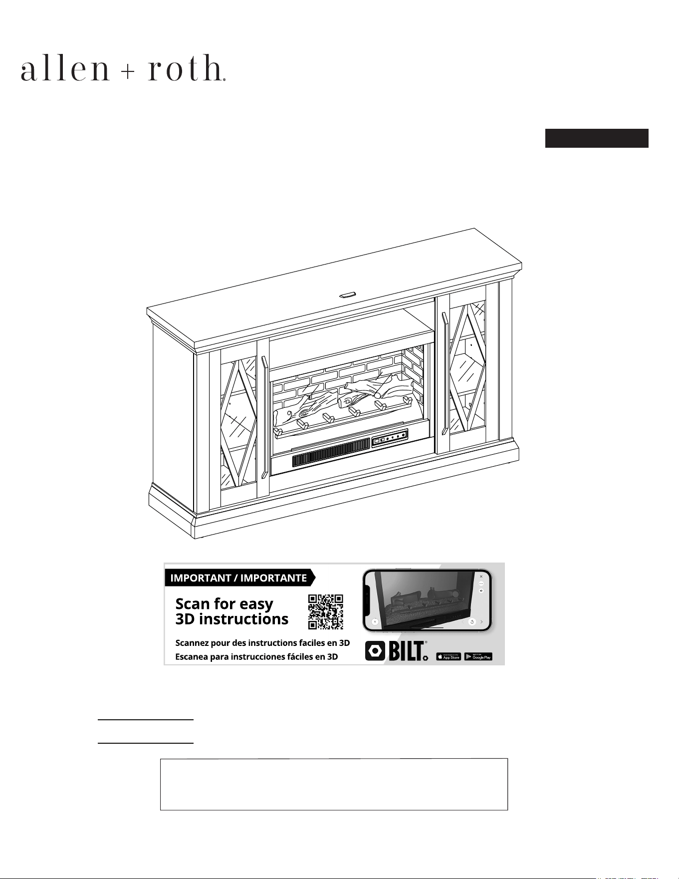
Thank you for purchasing this ALLEN + ROTH product.
Questions, problems or missing parts?
Before returning, contact us on:
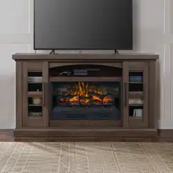
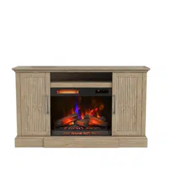
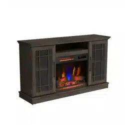
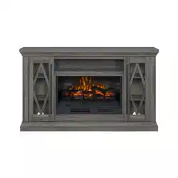
ITEM #5691736
MODEL #LWFP62-9
62-IN MEDIA FIREPLACE
Español p. 21
ALLEN + ROTH and logo design are
trademarks or registered trademarks of LF, LLC.
All rights reserved.
ATTACH YOUR RECEIPT HERE
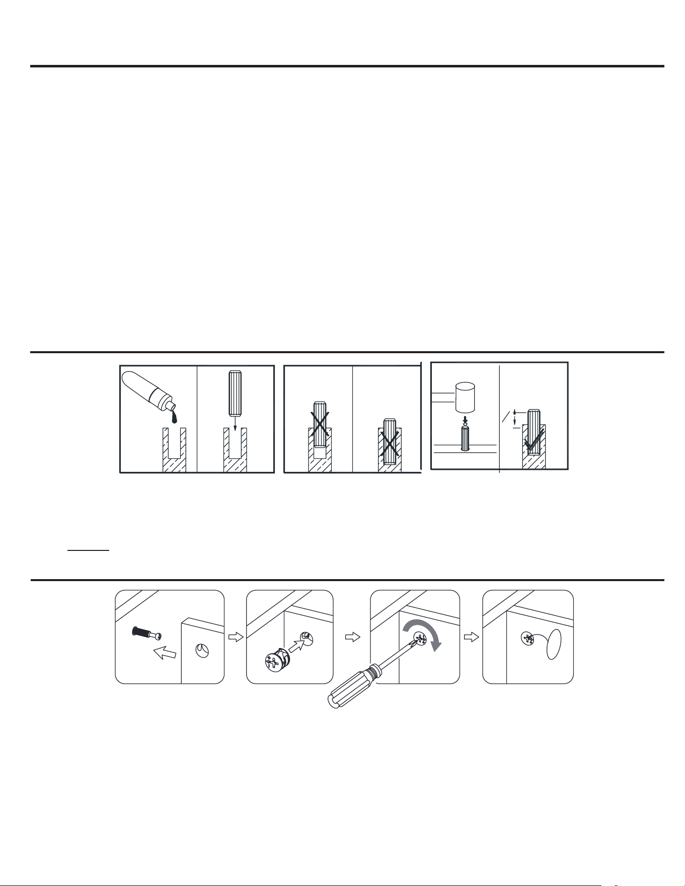
TABLE OF CONTENTS
Wood Dowel Installation .............................................................................................................................. 2
Package Contents ....................................................................................................................................... 3
Hardware Contents...................................................................................................................................... 4
Safety Information ....................................................................................................................................... 5
Preparation .................................................................................................................................................. 5
Assembly Instructions.................................................................................................................................. 6
Care and Maintenance .............................................................................................................................. 18
One-Year Warranty .................................................................................................................................... 18
Replacement Parts List ............................................................................................................................. 19
WOOD DOWEL INSTALLATION
1. Apply glue to each dowel prior to inserting the dowel into the hole. Excess glue can be wiped o
with damp cloth.
2. Insert dowel at least half way by tapping lightly with a rubber mallet if necessary.
NOTE: IT IS VERY IMPORTANT TO USE GLUE WITH DOWELS.
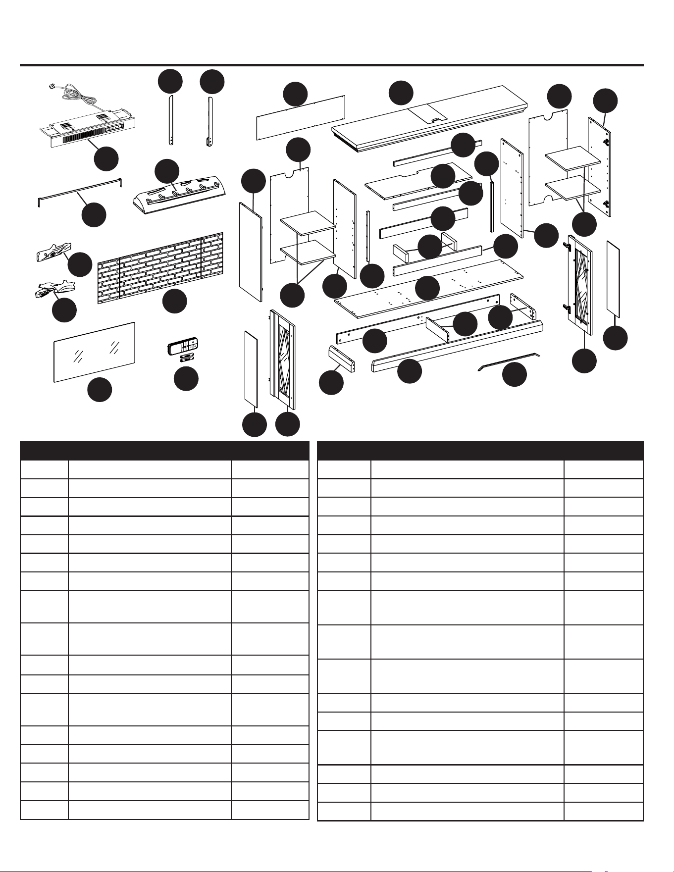
PACKAGE CONTENTS
PART DESCRIPTION QUANTITY
A Heater 1
B Left upright arm 1
C Right upright arm 1
D Connector strap 1
E Ember bed 1
F Left log 1
G Right log 1
H Firebox wall panel 1
I Firebox glass 1
J Remote control with battery 1
K Top panel 1
L Media shelf 1
M Bottom panel 1
N Rear skirting 1
O Front skirting 1
P Left skirting 1
Q Right skirting 1
PART DESCRIPTION QUANTITY
R Bottom middle stretcher 1
S Side panel 2
T Left partition panel 1
U Right partition panel 1
V Adjustable shelf 4
W Top front molding 1
X Middle crossbar 1
Y Firebox back holder 1
Z Firebox long support 1
A1 Firebox short support 2
B1 Middle trim 2
C1 Door with glass insert 2
D1 Wood door insert 2
E1 Middle back panel 1
F1 Side back panel 2
G1 Handle 2
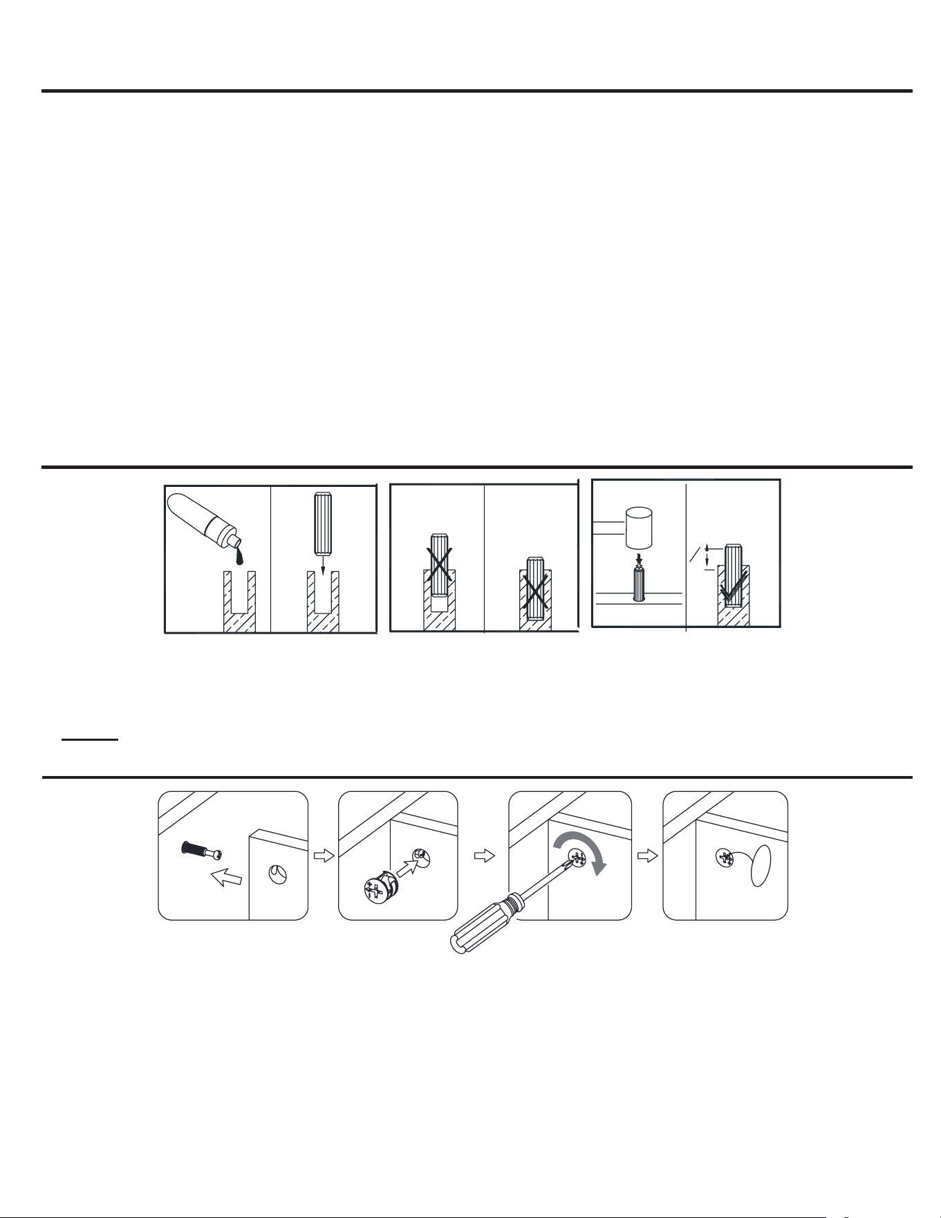
CAM LOCK SYSTEM OPERATION
1. Screw cam bolt into the pre-drilled small holes on panel. Connect both panels together; making sure
cam bolt goes into the pre-drilled hole on the end of panel for cam lock.
2. Insert the cam lock into the pre-drilled large hole on the panel. Make sure the arrow on the face of cam
lock faces out and points towards cam bolt.
3. Take a Phillips screwdriver and rotate the cam lock clockwise to lock the cam bolt in place.
4. Stick the paper sticker on the cam lock to conceal the cam.
GLUE
FINAL
43
1
3
1
2
O
L
M
S
U
W
X
Y
Z
A1
F1
V
R
Q
P
I
B1
H
J
K
B
C
D
E
F
G
T
C1
V
D1
A
S
E1
F1
D1
G1
C1
B1
N
32
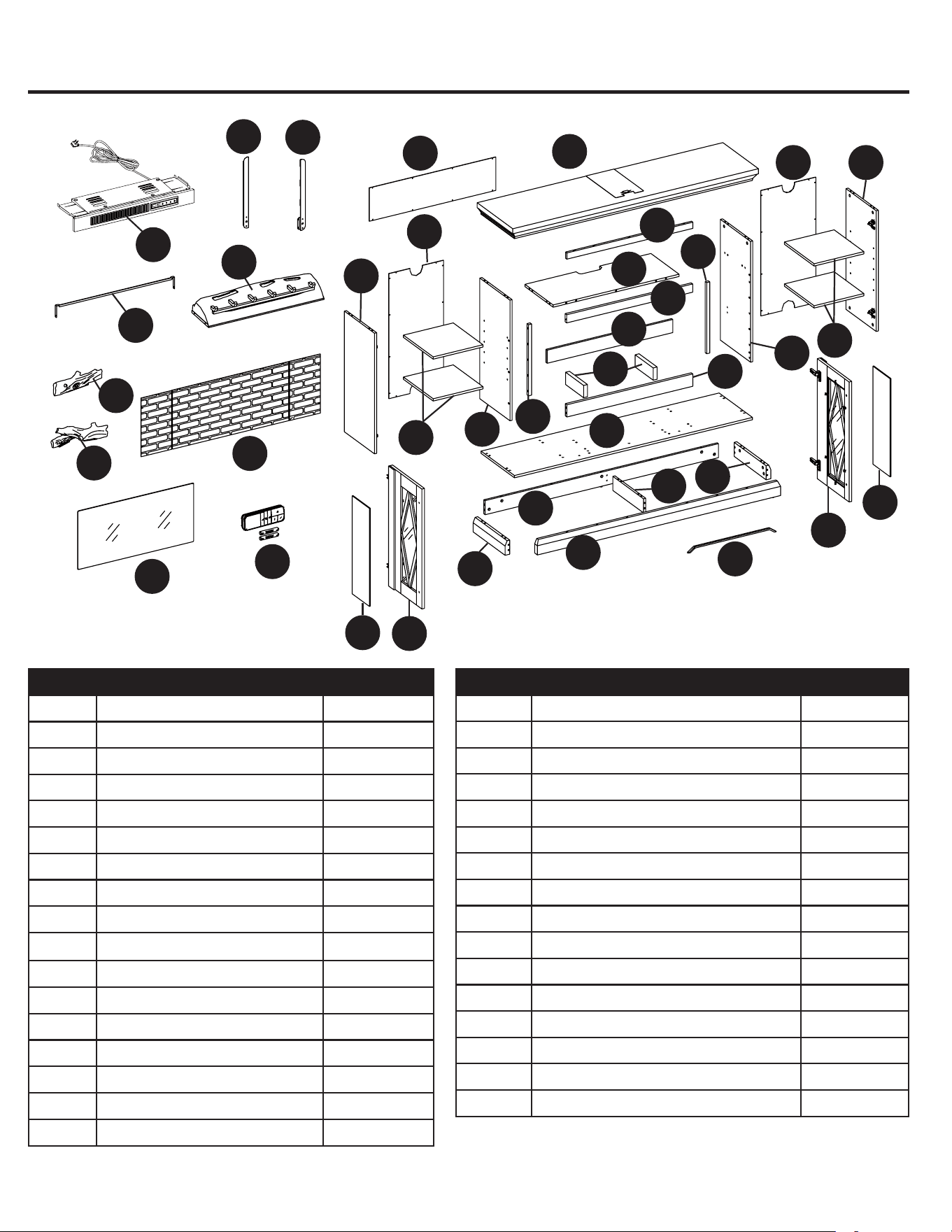
TABLE OF CONTENTS
Wood Dowel Installation .............................................................................................................................. 2
Package Contents ....................................................................................................................................... 3
Hardware Contents...................................................................................................................................... 4
Safety Information ....................................................................................................................................... 5
Preparation .................................................................................................................................................. 5
Assembly Instructions.................................................................................................................................. 6
Care and Maintenance .............................................................................................................................. 18
One-Year Warranty .................................................................................................................................... 18
Replacement Parts List ............................................................................................................................. 19
WOOD DOWEL INSTALLATION
1. Apply glue to each dowel prior to inserting the dowel into the hole. Excess glue can be wiped o
with damp cloth.
2. Insert dowel at least half way by tapping lightly with a rubber mallet if necessary.
NOTE: IT IS VERY IMPORTANT TO USE GLUE WITH DOWELS.
PACKAGE CONTENTS
PART DESCRIPTION QUANTITY
A Heater 1
B Left upright arm 1
C Right upright arm 1
D Connector strap 1
E Ember bed 1
F Left log 1
G Right log 1
H Firebox wall panel 1
I Firebox glass 1
J Remote control with battery 1
K Top panel 1
L Media shelf 1
M Bottom panel 1
N Rear skirting 1
O Front skirting 1
P Left skirting 1
Q Right skirting 1
PART DESCRIPTION QUANTITY
R Bottom middle stretcher 1
S Side panel 2
T Left partition panel 1
U Right partition panel 1
V Adjustable shelf 4
W Top front molding 1
X Middle crossbar 1
Y Firebox back holder 1
Z Firebox long support 1
A1 Firebox short support 2
B1 Middle trim 2
C1 Door with glass insert 2
D1 Wood door insert 2
E1 Middle back panel 1
F1 Side back panel 2
G1 Handle 2
CAM LOCK SYSTEM OPERATION
1. Screw cam bolt into the pre-drilled small holes on panel. Connect both panels together; making sure
cam bolt goes into the pre-drilled hole on the end of panel for cam lock.
2. Insert the cam lock into the pre-drilled large hole on the panel. Make sure the arrow on the face of cam
lock faces out and points towards cam bolt.
3. Take a Phillips screwdriver and rotate the cam lock clockwise to lock the cam bolt in place.
4. Stick the paper sticker on the cam lock to conceal the cam.
GLUE
FINAL
43
1
3
1
2
O
L
M
S
U
W
X
Y
Z
A1
F1
V
R
Q
P
I
B1
H
J
K
B
C
D
E
F
G
T
C1
V
D1
A
S
E1
F1
D1
G1
C1
B1
N
32

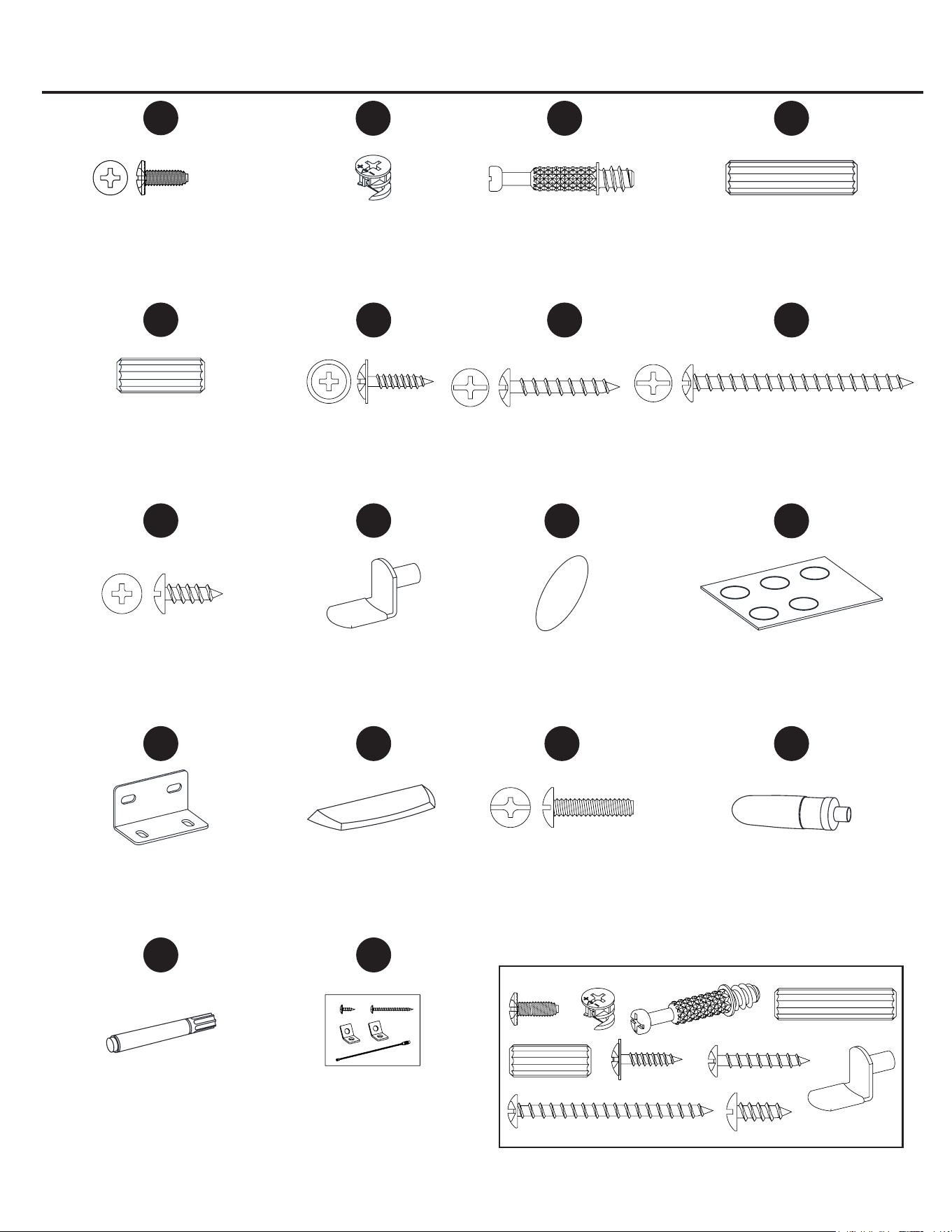
HARDWARE CONTENTS
(shown not actual size)
Touch-up Pen
Qty. 1
Glue
Qty. 2
Tipping Restraint
Hardware Kit
Qty. 2
Acrylic Stopper
Qty. 1
SAFETY INFORMATION
Please read and understand this entire manual before attempting to assemble, operate or install the
product.
• Do not allow children to climb or play in or around this product.
• Use this unit for its intended purpose only. Do not use shelves as step ladder.
• To avoid damage, assemble the product on a sturdy, level and protective surface.
• Two people should work together to assemble the unit.
• Make sure all bolts/screws are tightly fastened before the unit is used.
• Check bolts/screws periodically and tighten them if necessary.
• Do not push furniture, especially on carpeted oor. Have someone help you lift the item and place it in
its new location. Remove any shelves before moving.
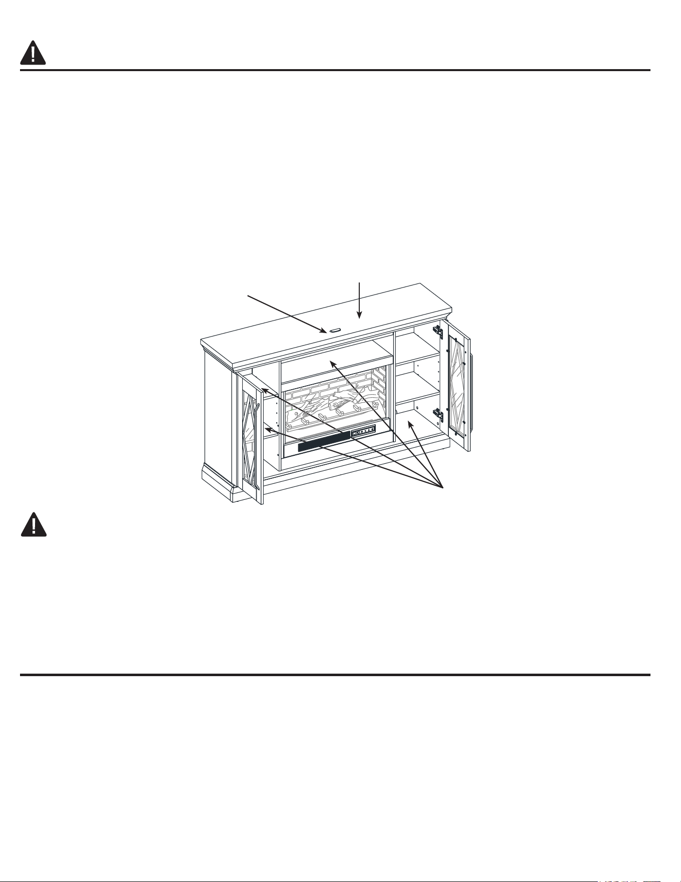
WARNING
This unit is not intended for use with CRT TVs. Use only with at panel TVs and audio/video equipment
meeting recommended size and weight limits. Never use with larger/heavier than recommended at panel
TVs or equipment. To avoid instability, place at panel TV in the center of the unit; the base of the
television must be able to rest on the supporting surface of the unit without over-hanging the edges.
Improperly positioned at panel TVs, or at panel TVs or other equipment that exceed recommended size
and weight limits could fall o or break the unit, causing possible serious injury.
PREPARATION
Before beginning assembly of product, make sure all parts are present. Compare parts with package
contents list and hardware contents list. If any part is missing or damaged, do not attempt to assemble the
product.
Estimated Assembly Time: 100 minutes
Tools Required for Assembly (not included): Phillips screwdriver, power drill, 1/8 in. drill bit, rubber mallet,
plier, marking pencil and hammer.
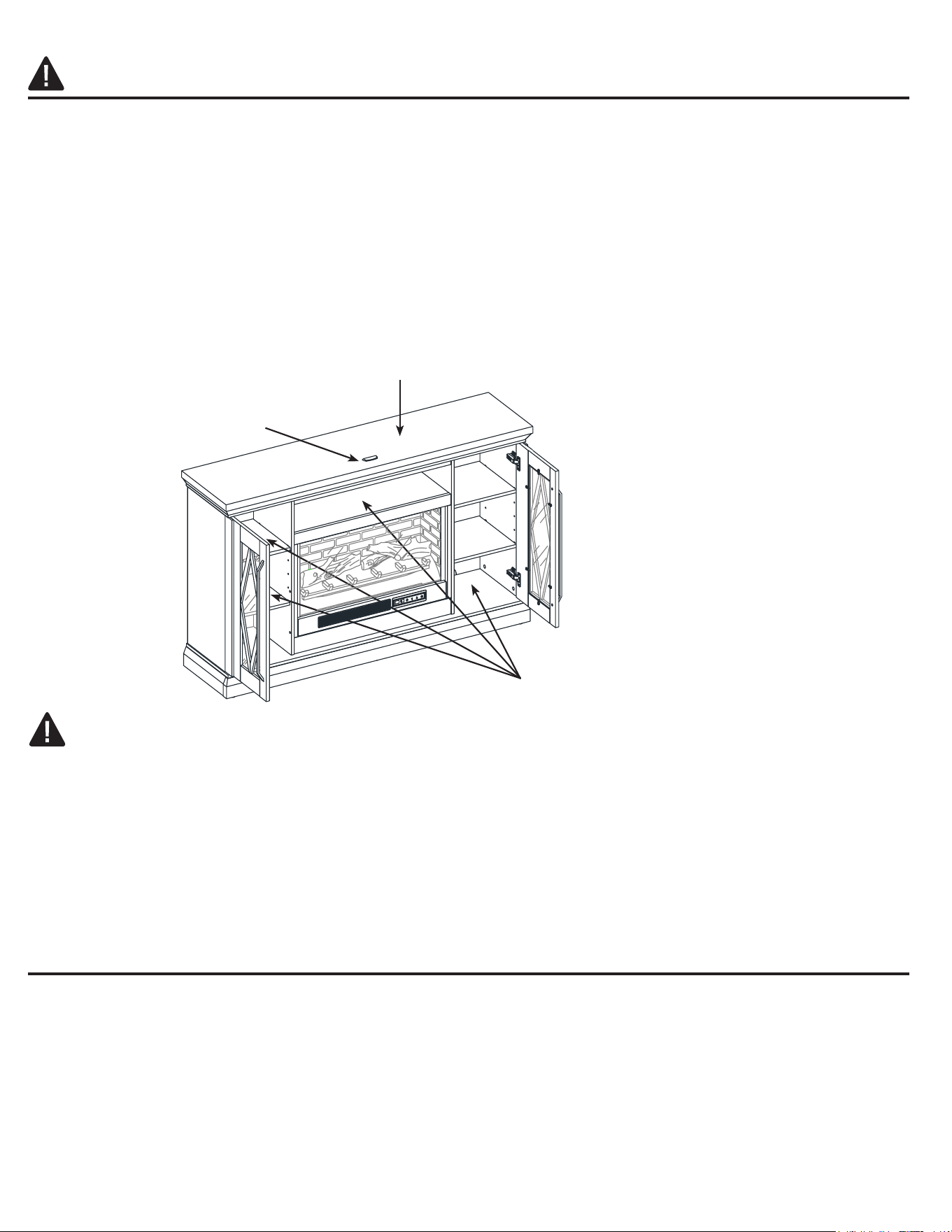
Place TV behind the stopper
Fits up to most 190.5 cm / 75 in. diagonal at panel TVs
Maximum load 36.28 kg / 80 lb
Maximum load 22.7 kg / 50 lb
DD
M8 x 30 mm Wood Dowel
Qty. 49
JJ
KK LL
RRQQ
II
Paper Sticker
Qty. 18+1 extra
Rubber Bumper
Qty. 4+1 extra
Shelf Support
Qty. 16
M3.5 x 13 mm
Pan Head Screw
Qty. 8
L-shaped Bracket
Qty. 2
Handle Bolt
Qty. 4
MM NN OO PP
M4 x 10 mm Screw
Qty. 10
AA
Cam Lock
Qty. 45
BB CC
Cam Bolt
Qty. 45
EE
M8 x 20 mm Wood Dowel
Qty. 4
M3 x 15 mm Washer
Head Screw
Qty. 40
FF GG
M4 x 25 mm Screw
Qty. 6
M4 x 50 mm Screw
Qty. 10
HH
Extra Hardware
54
HARDWARE CONTENTS
(shown not actual size)
Touch-up Pen
Qty. 1
Glue
Qty. 2
Tipping Restraint
Hardware Kit
Qty. 2
Acrylic Stopper
Qty. 1
SAFETY INFORMATION
Please read and understand this entire manual before attempting to assemble, operate or install the
product.
• Do not allow children to climb or play in or around this product.
• Use this unit for its intended purpose only. Do not use shelves as step ladder.
• To avoid damage, assemble the product on a sturdy, level and protective surface.
• Two people should work together to assemble the unit.
• Make sure all bolts/screws are tightly fastened before the unit is used.
• Check bolts/screws periodically and tighten them if necessary.
• Do not push furniture, especially on carpeted oor. Have someone help you lift the item and place it in
its new location. Remove any shelves before moving.
WARNING
This unit is not intended for use with CRT TVs. Use only with at panel TVs and audio/video equipment
meeting recommended size and weight limits. Never use with larger/heavier than recommended at panel
TVs or equipment. To avoid instability, place at panel TV in the center of the unit; the base of the
television must be able to rest on the supporting surface of the unit without over-hanging the edges.
Improperly positioned at panel TVs, or at panel TVs or other equipment that exceed recommended size
and weight limits could fall o or break the unit, causing possible serious injury.
PREPARATION
Before beginning assembly of product, make sure all parts are present. Compare parts with package
contents list and hardware contents list. If any part is missing or damaged, do not attempt to assemble the
product.
Estimated Assembly Time: 100 minutes
Tools Required for Assembly (not included): Phillips screwdriver, power drill, 1/8 in. drill bit, rubber mallet,
plier, marking pencil and hammer.
Place TV behind the stopper
Fits up to most 190.5 cm / 75 in. diagonal at panel TVs
Maximum load 36.28 kg / 80 lb
Maximum load 22.7 kg / 50 lb
DD
M8 x 30 mm Wood Dowel
Qty. 49
JJ
KK LL
RRQQ
II
Paper Sticker
Qty. 18+1 extra
Rubber Bumper
Qty. 4+1 extra
Shelf Support
Qty. 16
M3.5 x 13 mm
Pan Head Screw
Qty. 8
L-shaped Bracket
Qty. 2
Handle Bolt
Qty. 4
MM NN OO PP
M4 x 10 mm Screw
Qty. 10
AA
Cam Lock
Qty. 45
BB CC
Cam Bolt
Qty. 45
EE
M8 x 20 mm Wood Dowel
Qty. 4
M3 x 15 mm Washer
Head Screw
Qty. 40
FF GG
M4 x 25 mm Screw
Qty. 6
M4 x 50 mm Screw
Qty. 10
HH
Extra Hardware
54
30 mm Wood Dowel x 2
Cam Lock x 3
Glue x 1
Glue x 1
BB
DD
PP
PP
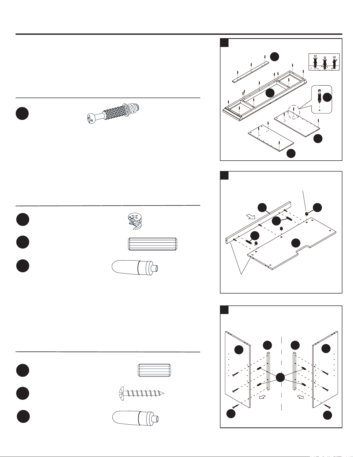
1
ASSEMBLY INSTRUCTIONS
3
2
Hardware Used
Hardware Used
20mm Wood Dowel x 4
M4 x 25 mm Screw x 6
GG
EE
L
K
T
T
U
U
X
X
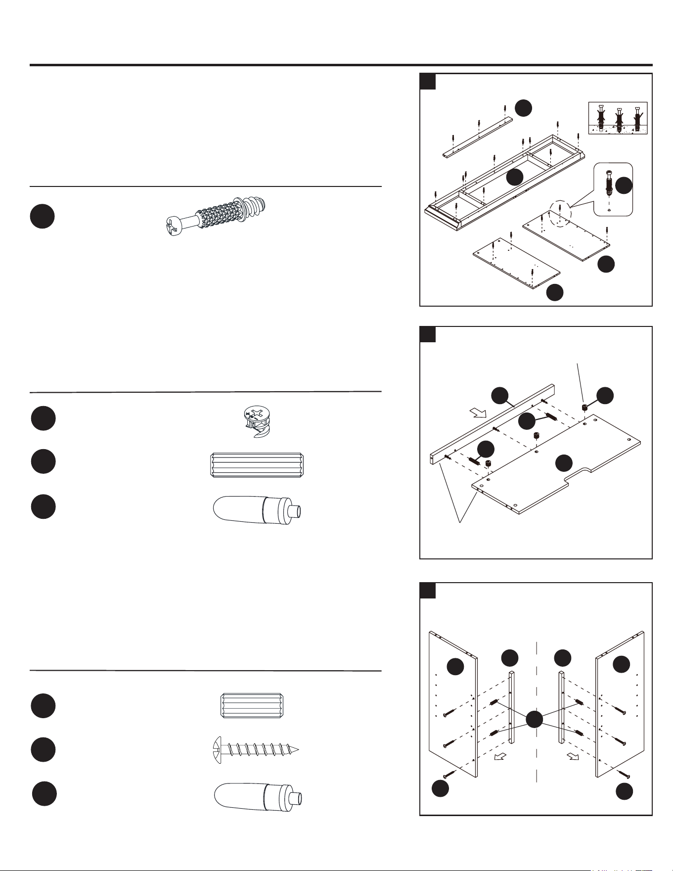
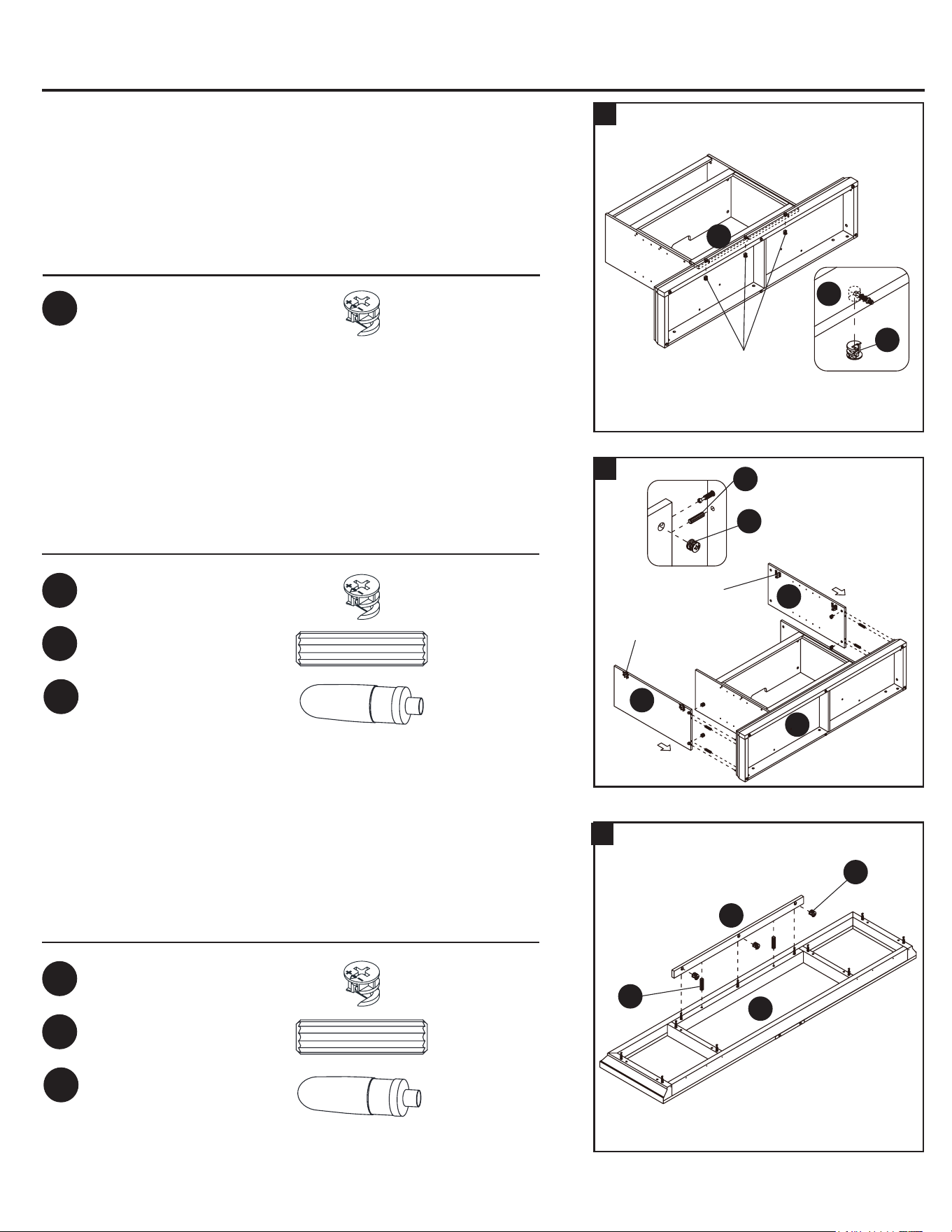
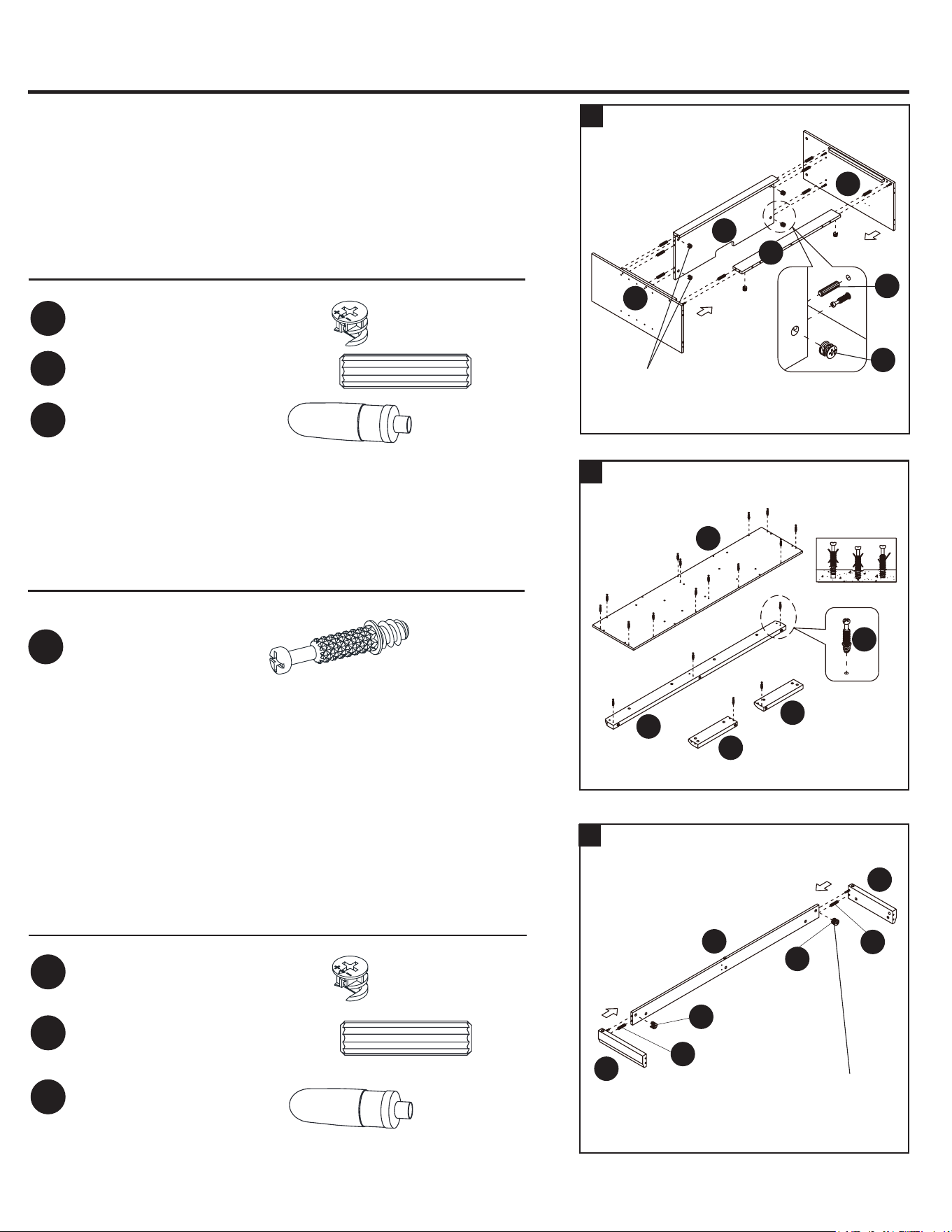
2. Glue two wood dowels (DD) into the inner holes of middle crossbar
(X) and attach it to the media shelf (L) by engaging three cam locks
(BB).
Hardware Used
Cam Bolt x 20
CC
EE
CC
GG
GG
DD
DD
BB
B1 B1
The cam locks
face upward
The top edges
are even
3a. Glue two 20 mm wood dowels (EE) into the inner holes of each
middle trim (B1).
3b. Fasten the middle trims (B1) to the partition panels (T and U) with
three 25 mm screws (GG) respectively.
ASSEMBLY INSTRUCTIONS
6
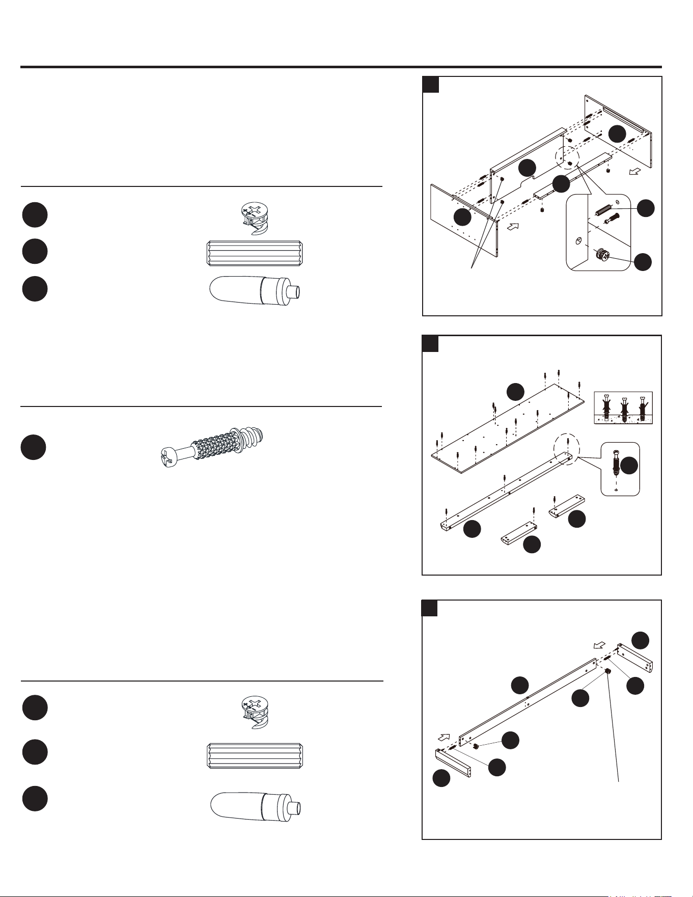
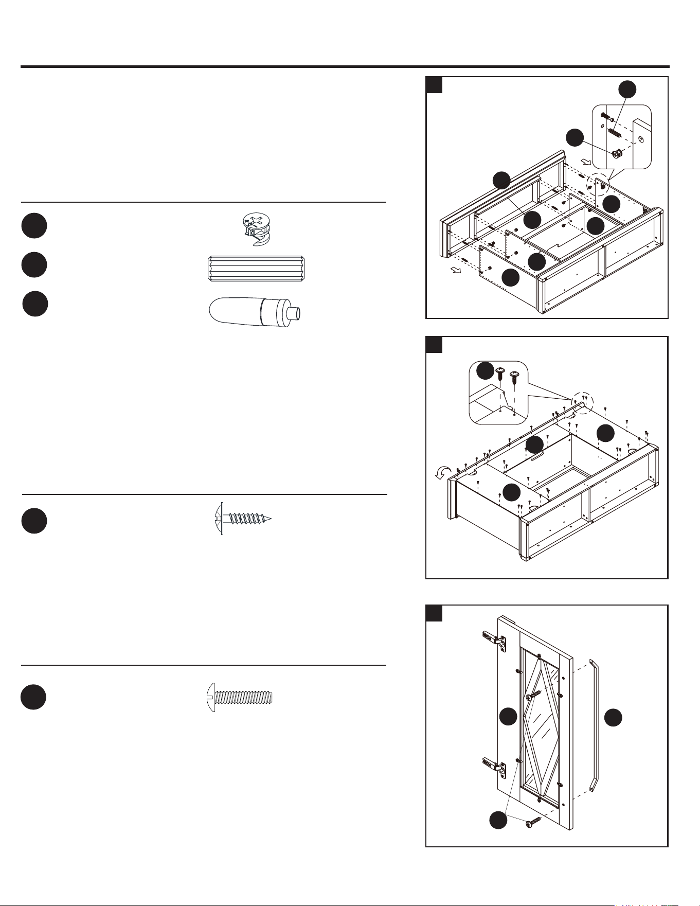
6. Glue two 30 mm wood dowels (DD) into the lower side holes of rear
skirting (N) and attach it between the side skirtings (P and Q) by
engaging two cam locks (BB).
5
4
N
O
L
P
P
Q
Q
M
T
U
CC
DD
DD
DD
BB
BB
BB
30 mm Wood Dowel x 8
Cam Lock x 6
Glue x 1
Hardware Used
4a. Glue two 30 mm wood dowels (DD) into the upper side holes of
rebox long support (Z) and six wood dowels (DD) to the media shelf
(L) of both ends.
4b. Attach the rebox long support (Z) and the media shelf (L) between
the partition panels (T and U) by engaging six cam locks (BB).
BB
DD
PP
5. Securely screw the cam bolts (CC) into the designated small holes on
the bottom panel (M), front skirting (O) and side skirtings (P and Q).
Fully tighten with a Phillips screwdriver.
Hardware Used
Cam Bolt x 18
CC
30 mm Wood Dowel x 2
Cam Lock x 2
Glue x 1
BB
DD
PP
Hardware Used
The cam locks
face inward
The cam locks
face inward
1a. Unpack the unit and conrm that you have all the hardware and
required parts. Assemble the unit on a carpeted oor or the empty
carton to avoid any scratch.
1b. Securely screw the cam bolts (CC) into the designated small holes
on the top panel (K), middle crossbar (X) and partition panels
(T and U). Fully tighten with a Phillips screwdriver.
Z
76
30 mm Wood Dowel x 2
Cam Lock x 3
Glue x 1
Glue x 1
BB
DD
PP
PP
1
ASSEMBLY INSTRUCTIONS
3
2
Hardware Used
Hardware Used
20mm Wood Dowel x 4
M4 x 25 mm Screw x 6
GG
EE
L
K
T
T
U
U
X
X
2. Glue two wood dowels (DD) into the inner holes of middle crossbar
(X) and attach it to the media shelf (L) by engaging three cam locks
(BB).
Hardware Used
Cam Bolt x 20
CC
EE
CC
GG
GG
DD
DD
BB
B1 B1
The cam locks
face upward
The top edges
are even
3a. Glue two 20 mm wood dowels (EE) into the inner holes of each
middle trim (B1).
3b. Fasten the middle trims (B1) to the partition panels (T and U) with
three 25 mm screws (GG) respectively.
ASSEMBLY INSTRUCTIONS
6
6. Glue two 30 mm wood dowels (DD) into the lower side holes of rear
skirting (N) and attach it between the side skirtings (P and Q) by
engaging two cam locks (BB).
5
4
N
O
L
P
P
Q
Q
M
T
U
CC
DD
DD
DD
BB
BB
BB
30 mm Wood Dowel x 8
Cam Lock x 6
Glue x 1
Hardware Used
4a. Glue two 30 mm wood dowels (DD) into the upper side holes of
rebox long support (Z) and six wood dowels (DD) to the media shelf
(L) of both ends.
4b. Attach the rebox long support (Z) and the media shelf (L) between
the partition panels (T and U) by engaging six cam locks (BB).
BB
DD
PP
5. Securely screw the cam bolts (CC) into the designated small holes on
the bottom panel (M), front skirting (O) and side skirtings (P and Q).
Fully tighten with a Phillips screwdriver.
Hardware Used
Cam Bolt x 18
CC
30 mm Wood Dowel x 2
Cam Lock x 2
Glue x 1
BB
DD
PP
Hardware Used
The cam locks
face inward
The cam locks
face inward
1a. Unpack the unit and conrm that you have all the hardware and
required parts. Assemble the unit on a carpeted oor or the empty
carton to avoid any scratch.
1b. Securely screw the cam bolts (CC) into the designated small holes
on the top panel (K), middle crossbar (X) and partition panels
(T and U). Fully tighten with a Phillips screwdriver.
Z
76
9
ASSEMBLY INSTRUCTIONS
8
7
O
O
R
P
Q
M
DD
BB
BB
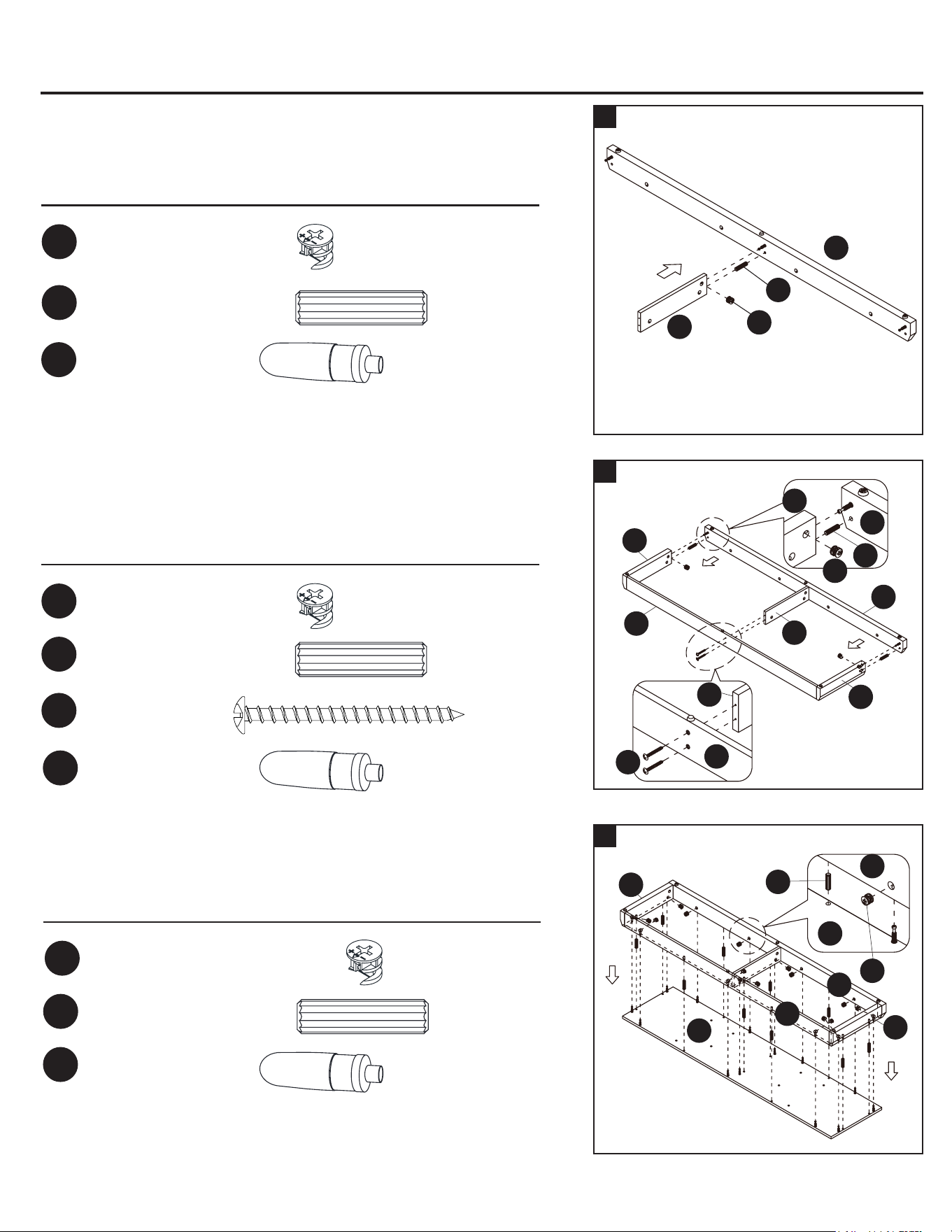
7. Glue one wood dowel (DD) into the designated hole on the bottom
middle stretcher (R) and attached it to the front skirting (O) by
engaging one cam lock (BB).
Cam Lock x 1
BB
Hardware Used
30 mm Wood Dowel x 2
30 mm Wood Dowel x 10
Cam Lock x 2
Cam Lock x 13
M4 x 50 mm screw
x 2
M4 x 50 mm screw
x 4
Glue x 1
Glue x 1
Glue x 1
BB
BB
DD
DD
HH
HH
PP
PP
PP
Hardware Used
Hardware Used
8a. Glue two 30 mm wood dowels (DD) to the lower side holes on the
side skirtings (P and Q) and attach them to the front skirting (O) by
engaging two cam locks (BB).
8b. Insert two 50 mm screws (HH) through the rear skirting (N) and
securely screw into the bottom middle stretcher (R).
9. Glue the 30 mm wood dowels (DD) to the inner holes on the base
frame assembly and attach it to the bottom panel (M) by engaging
thirteen cam locks (BB).
ASSEMBLY INSTRUCTIONS
10
M
M
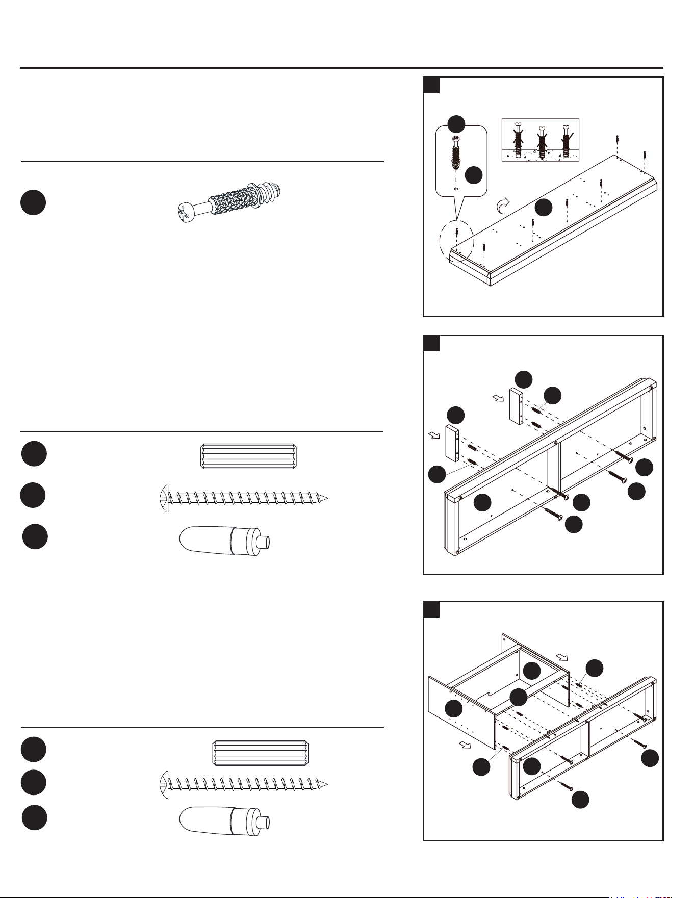
10a. Ask for assistance to turn the base upright.
10b. Securely screw seven cam bolts (CC) into the designated
small holes on the bottom panel (M). Fully tighten with a Phillips
screwdriver.
Hardware Used
Cam Bolt x 7
CC
30 mm Wood Dowel x 4
Glue x 1
DD
PP
Hardware Used
11a. Glue two 30 mm wood dowels (DD) into the inner holes on each
rebox short support (A1) and attach them to the bottom panel
(M).
11b. Fasten the rebox short supports (A1) to the bottom panel (M) with
four 50 mm screws (HH).
12
11
M
HH
A1
A1
HH
HH
HH
DD
DD
30 mm Wood Dowel x 1
DD
M
T
U
HH
HH
DD
DD
30 mm Wood Dowel x 6
M4 x 50 mm screw
x 4
Glue x 1
DD
HH
PP
Hardware Used
12a. Glue six 30 mm wood dowels (DD) to inner holes on the partition
panels (T and U) and rebox long support (Z).
12b. Align the large holes on the bottom panel (M) with the inserted
dowels on the partition panels (T and U) and the rebox long
support (Z) and press them together.
12c. Insert four 50 mm screws (HH) through the mounting holes on the
bottom panel (M) and securely screw into partition panels (T and U).
N
N
O
O
R
R
P
P
Q
HH
DD
BB
O
N
M
CC
DD
Z
98
9
ASSEMBLY INSTRUCTIONS
8
7
O
O
R
P
Q
M
DD
BB
BB
7. Glue one wood dowel (DD) into the designated hole on the bottom
middle stretcher (R) and attached it to the front skirting (O) by
engaging one cam lock (BB).
Cam Lock x 1
BB
Hardware Used
30 mm Wood Dowel x 2
30 mm Wood Dowel x 10
Cam Lock x 2
Cam Lock x 13
M4 x 50 mm screw
x 2
M4 x 50 mm screw
x 4
Glue x 1
Glue x 1
Glue x 1
BB
BB
DD
DD
HH
HH
PP
PP
PP
Hardware Used
Hardware Used
8a. Glue two 30 mm wood dowels (DD) to the lower side holes on the
side skirtings (P and Q) and attach them to the front skirting (O) by
engaging two cam locks (BB).
8b. Insert two 50 mm screws (HH) through the rear skirting (N) and
securely screw into the bottom middle stretcher (R).
9. Glue the 30 mm wood dowels (DD) to the inner holes on the base
frame assembly and attach it to the bottom panel (M) by engaging
thirteen cam locks (BB).
ASSEMBLY INSTRUCTIONS
10
M
M
10a. Ask for assistance to turn the base upright.
10b. Securely screw seven cam bolts (CC) into the designated
small holes on the bottom panel (M). Fully tighten with a Phillips
screwdriver.
Hardware Used
Cam Bolt x 7
CC
30 mm Wood Dowel x 4
Glue x 1
DD
PP
Hardware Used
11a. Glue two 30 mm wood dowels (DD) into the inner holes on each
rebox short support (A1) and attach them to the bottom panel
(M).
11b. Fasten the rebox short supports (A1) to the bottom panel (M) with
four 50 mm screws (HH).
12
11
M
HH
A1
A1
HH
HH
HH
DD
DD
30 mm Wood Dowel x 1
DD
M
T
U
HH
HH
DD
DD
30 mm Wood Dowel x 6
M4 x 50 mm screw
x 4
Glue x 1
DD
HH
PP
Hardware Used
12a. Glue six 30 mm wood dowels (DD) to inner holes on the partition
panels (T and U) and rebox long support (Z).
12b. Align the large holes on the bottom panel (M) with the inserted
dowels on the partition panels (T and U) and the rebox long
support (Z) and press them together.
12c. Insert four 50 mm screws (HH) through the mounting holes on the
bottom panel (M) and securely screw into partition panels (T and U).
N
N
O
O
R
R
P
P
Q
HH
DD
BB
O
N
M
CC
DD
Z
98
15
16
ASSEMBLY INSTRUCTIONS
14
13
M
S
S
DD
BB
BB
Hardware Used
13. Fasten the rebox long support (Z) to the bottom panel (M) by
engaging three cam locks (BB).
30 mm Wood Dowel x 4
30 mm Wood Dowel x 2
30 mm Wood Dowel x 8
Cam Lock x 4
Cam Lock x 3
Cam Lock x 8
Cam Lock x 3
Glue x 1
Glue x 1
Glue x 1
BB
BB
BB
BB
DD
DD
DD
PP
PP
PP
Hardware Used
Hardware Used
Hardware Used
14. Glue four 30 mm wood dowels (DD) to the bottom inner holes on the
side panels (S) and attach them to the bottom panel (M) by engaging
four cam locks (BB).
The hinge bases face
inward and are located at
front of the unit.
16a. Glue eight wood dowels (DD) to the top inner holes of the
vertical panels (S, T and U).
16b. Ask for assistance to position the top panel (K) onto the
inserted wood dowels (DD) and attach it into place by
engaging eight cam locks (BB).
16c. Now, go back and securely tighten all the cam locks and screws.
Make sure all the parts are tight and there are no gaps between the
parts. This will help keep the unit square.
K
T
S
S
W
U
DD
BB
ASSEMBLY INSTRUCTIONS
Hardware Used
Washer Head Screw x 40
FF
17a. Ask for assistance to ip around the previous assembly at its front
edges.
17b. Pick up the middle back panel (E1) and align the pre-drilled holes
against the upper long edge with the pilot holes on the back of top
panel (K). Fasten it in place with the provided washer head screw
(FF).
17c. Using the pilot holes as a guide, align and attach the side back pan-
els (F1) to the mantel frame with the washer head screws (FF).
17
F1
F1
18. Attach one handle (G1) to the front side of each door (C1) with the
provided handle bolts (OO).
Hardware Used
Handle Bolt x 4
OO
18
C1
G1
OO
x 2
15. Glue two wood dowels (DD) into the inner holes on the top front
molding (W) and attach it to the top panel (K) by engaging three cam
locks (BB).
Z
Z
The cam locks
face inward
K
W
DD
BB
E1
FF
1110

ASSEMBLY INSTRUCTIONS
ASSEMBLY INSTRUCTIONS
19a. Ask for assistance to stand the unit upright.
19b. Pick up one door (C1) and attach the extended hinge arms to the
hinge bases installed on the left side panel (S). Loosen the bolt on
the back of the hinge base for an easy t. Align and insert the “U” slot
on the hinge arm under the bolt head on the back of the hinge base.
Make sure that both door hinges engage and function properly.
Tighten the bolt on the hinge base to lock the hinges in place.
19c. Repeat the same process to attach the other door (C1) at the
opposite side.
19d. Open and close the doors to make sure they are aligned and shut
correctly. If necessary, adjust the screws for a good t. Refer to the
hinge sticker on the door for adjustment.
19
S
S
T
U
C1
C1
1
2
1
2
V
V
JJ
JJ
Hardware Used
Shelf Support x 16
JJ
20. Insert eight shelf supports (JJ) into the desired holes inside each side
compartment. Make sure you place the four shelf supports at the
same level to level the shelf. Tilt and rest the adjustable shelves (V)
onto the shelf supports (JJ).
21
Hardware Used
Paper Sticker x 18
Rubber Bumper x 4
KK
LL
21a. Put the paper stickers (KK) onto the visible cam locks and screws.
21b. Stick the rubber bumpers (LL) on the outer corners of doors where
are in contact with the partition panels (T and U).
20
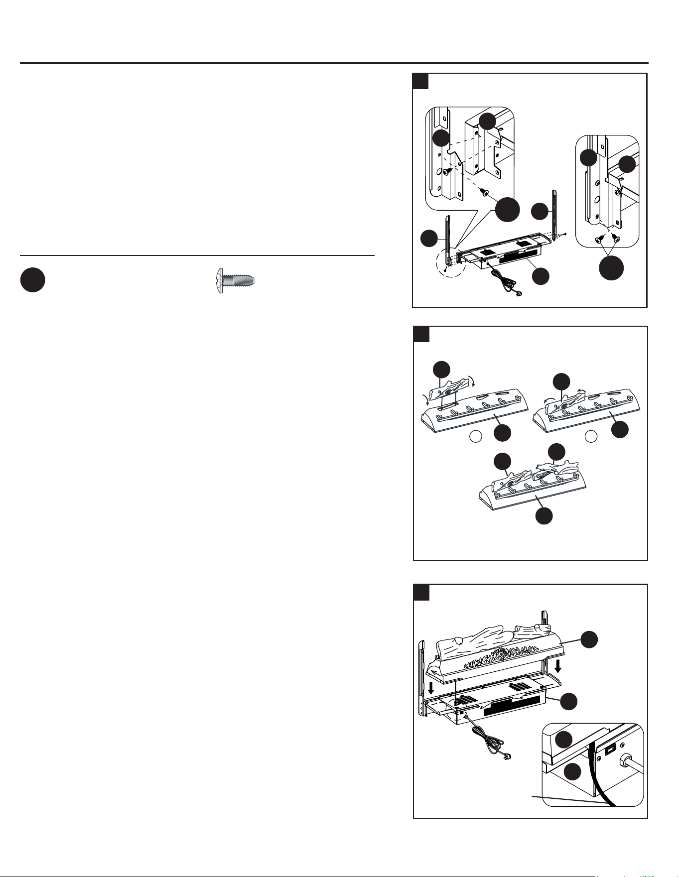
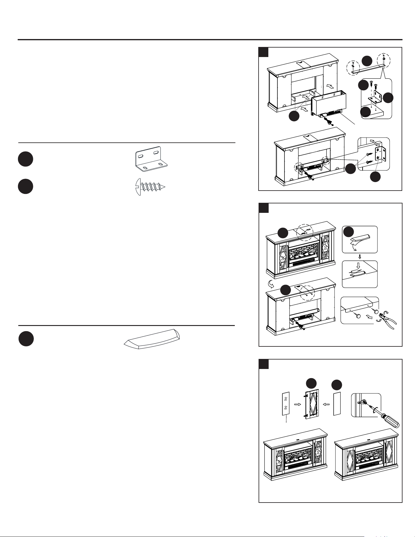
Installing the replace insert
22
22a. See gure A: Fasten upper 2 screws (AA) through the upright arm
(C) into the heater (A) until tight.
22b. See gure B: Fasten lower 2 screws (AA) into the upright arm (C)
until tight.
22c. Fully tighten all 4 screws (AA) one nal time.
22d. Repeat the same process with upright arm (B).
IMPORTANT NOTE: Use hand screwdriver, not power driver to assemble
replace insert. See BILT for video instructions.
WARNING: Do not lift or transport the heater by using the upright arms.
Hardware Used
M4 x 10 mm Screw x 8
AA
1
2
IMPORTANT: Carefully follow the 2 steps below for inserting each log.
23
23a. Install left log (F) into left hole of ember bed (E) by inserting front
edge of base of the log into front notches of ember bed hole.
23b. Then tilt the log back to insert the rear edge of the log base into rear
notches of ember bed hole (press down log rmly to lock into
position).
23c. Repeat the above process for the right log (G).
E
E
E
F
F
F
G
24
24a. Set the ember bed (E) onto the heater (A) as shown.
24b. Push ember bed forward against the front ange of heater.
24c. Position the USB cable as shown.
T
C1
LL
LL
U
KK
Figure A
Figure B
B
C
C
C
A
A
A
AA
AA
E
E
A
A
USB cable
1312
ASSEMBLY INSTRUCTIONS
ASSEMBLY INSTRUCTIONS
19a. Ask for assistance to stand the unit upright.
19b. Pick up one door (C1) and attach the extended hinge arms to the
hinge bases installed on the left side panel (S). Loosen the bolt on
the back of the hinge base for an easy t. Align and insert the “U” slot
on the hinge arm under the bolt head on the back of the hinge base.
Make sure that both door hinges engage and function properly.
Tighten the bolt on the hinge base to lock the hinges in place.
19c. Repeat the same process to attach the other door (C1) at the
opposite side.
19d. Open and close the doors to make sure they are aligned and shut
correctly. If necessary, adjust the screws for a good t. Refer to the
hinge sticker on the door for adjustment.
19
S
S
T
U
C1
C1
1
2
1
2
V
V
JJ
JJ
Hardware Used
Shelf Support x 16
JJ
20. Insert eight shelf supports (JJ) into the desired holes inside each side
compartment. Make sure you place the four shelf supports at the
same level to level the shelf. Tilt and rest the adjustable shelves (V)
onto the shelf supports (JJ).
21
Hardware Used
Paper Sticker x 18
Rubber Bumper x 4
KK
LL
21a. Put the paper stickers (KK) onto the visible cam locks and screws.
21b. Stick the rubber bumpers (LL) on the outer corners of doors where
are in contact with the partition panels (T and U).
20
Installing the replace insert
22
22a. See gure A: Fasten upper 2 screws (AA) through the upright arm
(C) into the heater (A) until tight.
22b. See gure B: Fasten lower 2 screws (AA) into the upright arm (C)
until tight.
22c. Fully tighten all 4 screws (AA) one nal time.
22d. Repeat the same process with upright arm (B).
IMPORTANT NOTE: Use hand screwdriver, not power driver to assemble
replace insert. See BILT for video instructions.
WARNING: Do not lift or transport the heater by using the upright arms.
Hardware Used
M4 x 10 mm Screw x 8
AA
1
2
IMPORTANT: Carefully follow the 2 steps below for inserting each log.
23
23a. Install left log (F) into left hole of ember bed (E) by inserting front
edge of base of the log into front notches of ember bed hole.
23b. Then tilt the log back to insert the rear edge of the log base into rear
notches of ember bed hole (press down log rmly to lock into
position).
23c. Repeat the above process for the right log (G).
E
E
E
F
F
F
G
24
24a. Set the ember bed (E) onto the heater (A) as shown.
24b. Push ember bed forward against the front ange of heater.
24c. Position the USB cable as shown.
T
C1
LL
LL
U
KK
Figure A
Figure B
B
C
C
C
A
A
A
AA
AA
E
E
A
A
USB cable
1312
ASSEMBLY INSTRUCTIONS ASSEMBLY INSTRUCTIONS
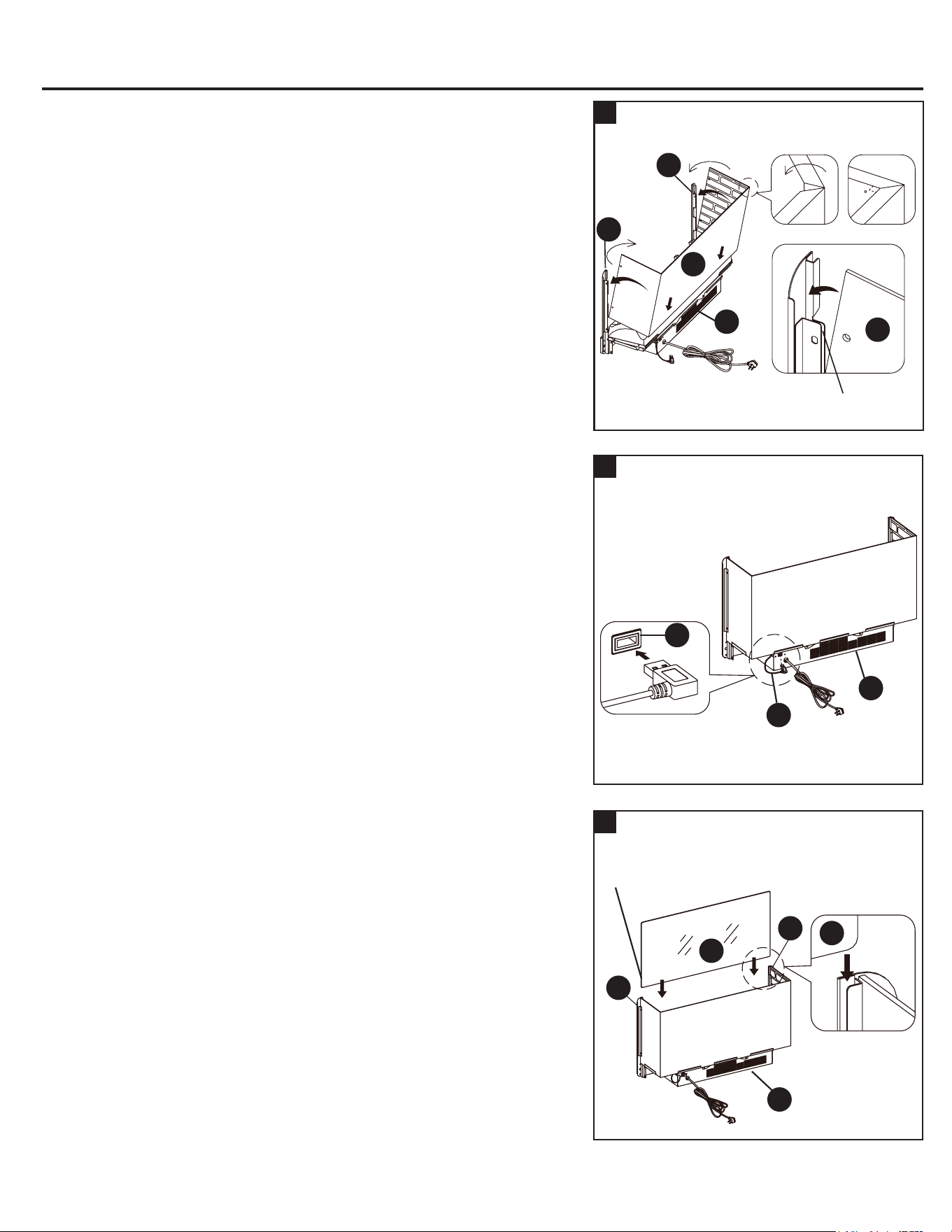
25
25a. Fold the wall panel (H) as shown. Then position yourself at back
side of heater (A).
25b. Hold wall panel (H) at the angle shown below and insert lower back
edge into metal slots on back of heater (A).
25c. Tilt wall panel (H) forward until bottom corner inserts into lower
U-channels on both upright arms (B and C).
25d. Continue to tilt wall panel (H) forward until the top corner inserts
into upper U-channels on both upright arms (B and C).
B
C
A
H
H
U-channel
26
26. Fully plug the USB connector of the ember bed (E) into the back port
of heater (A).
E
A
A
27
27. Slide the glass (I) into the inner U-channels on both upright arms
(B and C) until the glass sits onto the heater (A). If needed, push top
of upright arms in or out to accommodate glass. Make sure the top of
the glass (I) is ush with the top of both upright arms (B and C).
I
I
A
B
C
The warning labels on glass
should face outward
28. Position top connector strap (D) over the glass (I) and upright arms
(B and C). Follow orientation shown below.
28
B
C
D
D
H
H
The bevel edge
faces inside the unit.
29. Fasten connector strap (D) to both upright arms (B and C) using
two screws (AA) as show below. Holes must be in line for screw to
pass through.
30. The rebox is now ready for the next assembly step.
Hardware Used
30
29
B
C
H
H
D
D
AA
M4 x 10 mm Screw x 2
AA
90
I
1514

ASSEMBLY INSTRUCTIONS ASSEMBLY INSTRUCTIONS
25
25a. Fold the wall panel (H) as shown. Then position yourself at back
side of heater (A).
25b. Hold wall panel (H) at the angle shown below and insert lower back
edge into metal slots on back of heater (A).
25c. Tilt wall panel (H) forward until bottom corner inserts into lower
U-channels on both upright arms (B and C).
25d. Continue to tilt wall panel (H) forward until the top corner inserts
into upper U-channels on both upright arms (B and C).
B
C
A
H
H
U-channel
26
26. Fully plug the USB connector of the ember bed (E) into the back port
of heater (A).
E
A
A
27
27. Slide the glass (I) into the inner U-channels on both upright arms
(B and C) until the glass sits onto the heater (A). If needed, push top
of upright arms in or out to accommodate glass. Make sure the top of
the glass (I) is ush with the top of both upright arms (B and C).
I
I
A
B
C
The warning labels on glass
should face outward
28. Position top connector strap (D) over the glass (I) and upright arms
(B and C). Follow orientation shown below.
28
B
C
D
D
H
H
The bevel edge
faces inside the unit.
29. Fasten connector strap (D) to both upright arms (B and C) using
two screws (AA) as show below. Holes must be in line for screw to
pass through.
30. The rebox is now ready for the next assembly step.
Hardware Used
30
29
B
C
H
H
D
D
AA
M4 x 10 mm Screw x 2
AA
90
I
1514
ASSEMBLY INSTRUCTIONS
ASSEMBLY INSTRUCTIONS
Hardware Used
L-shaped Bracket x 2
Pan Head Screw x 8
MM
II
31a. Lift the fireplace insert carefully onto the firebox short supports
(A1) and in the back of the assembled mantel and center it in the
opening. DO NOT drag the insert across the rebox short supports
as it may scratch them.
31b. Use the pilot holes as a guide, fasten two L-shaped brackets (MM)
onto the rebox back holder (Y) with four pan head screws (II).
Make sure that the right angle side is ush with the short edge of
rebox back holder (Y).
31c. Fasten the rebox back holder (Y) between the partition panels
(T and U) with four screws (II), using the pilot holes as a guide.
31
Y
Y
II
MM
A1
Electric Firebox
MM
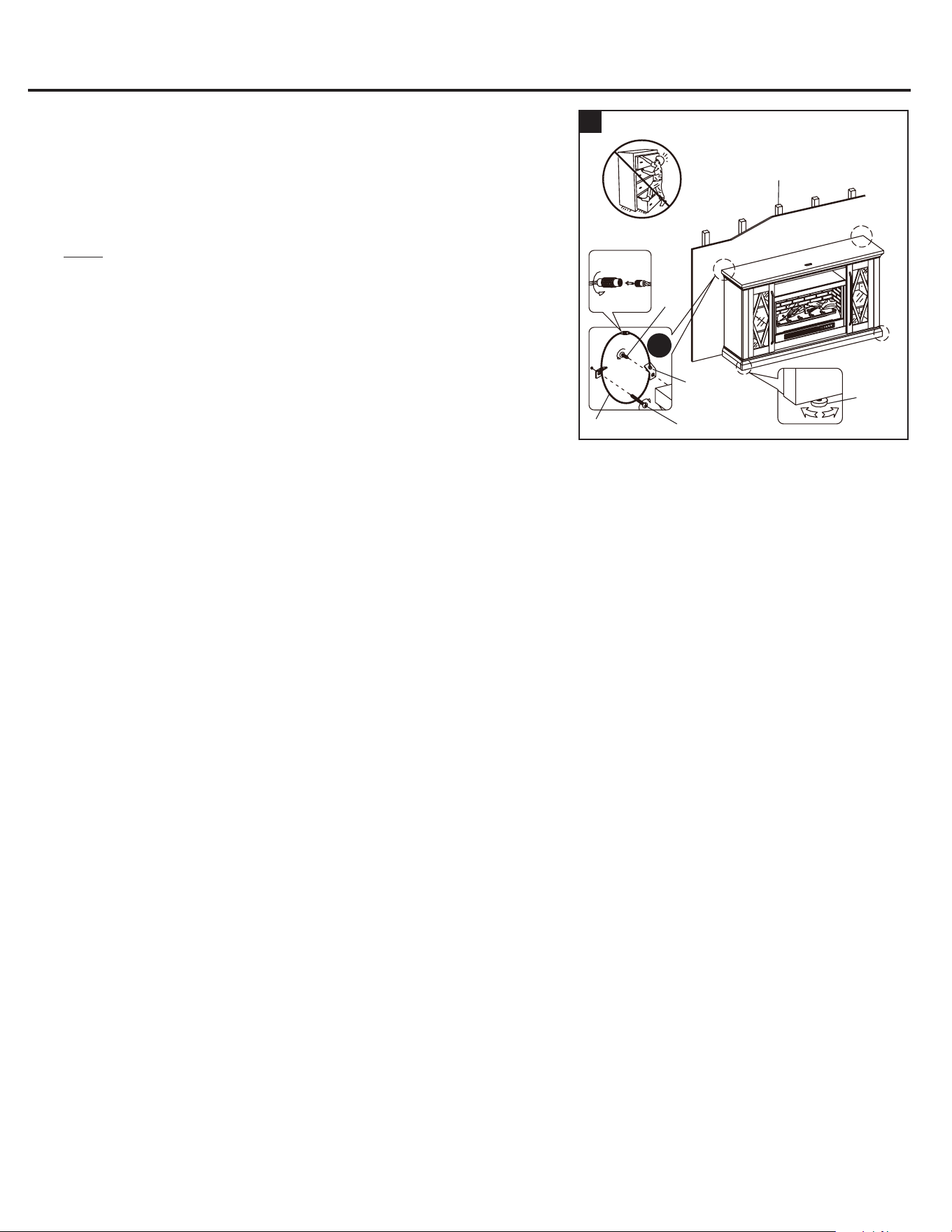
32
33
32a. Remove the paper backing from acrylic stopper (NN), then
properly align the acrylic stopper into the cut-out on the acrylic
stopper template on the front of the top panel (K). Press down on the
acrylic stopper to help adhesion.
32b. At the back of top panel (K), grip the head of plastic tack with pliers,
with twisting motion pull tack loose to remove the acrylic stopper
template.
NOTE: You must install the acrylic TV stopper to prevent TV
from tipping when placing your at panel television on the top
panel.
Hardware Used
Acrylic Stopper
x 1
NN
Follow these steps if you want to change your replace door panels from
glass to wood (D1). Otherwise, skip to Step “34”.
NOTE: To prevent your TV from tipping, you must install the acrylic TV
stopper if you place a at panel television on the top panel. Otherwise,
skip to step “32b”.
33a. Take one door (C1) and loosen the screws on the inside of the door
frame.
33b. Rotate the clips to remove the old panel.
33c. Insert the new panel, then rotate the clips and tighten the screws to
secure the panel in the door frame.
33d. Repeat this process with the other door (C1).
C1
D1
Glass door panel
34
Wooden stud
Short
Screw
Connector
Metal
Bracket
Long ScrewSteel Cable
Floor
Leveler
Wall
34a. Adjust oor levelers to level the unit at your desire location against
the wall.
34b. Now, follow the instructions printed on the plastic bag containing the
Tipping Restraint Hardware to attach the tip-over restraints to the
unit and the wall.
NOTE: Young children can be seriously injured by tipping
furniture. You must install the tipping restraint hardware with the
unit to prevent the unit from tipping, causing any accidents or
damage. The tipping restraints are intended only as a deterrent,
they are not a substitute for proper adult supervision. The tipping
restraints are not earthquake restraints. If you wish to add the extra
security of earthquake restraints, they must be purchased and
installed separately.
34c. Connect the fireplace to the power transformer. Follow the
operating manual for the electric fireplace insert to control your
fireplace.
Installing the tipping restraint hardware
RR
II
NN
K
K
1716
ASSEMBLY INSTRUCTIONS
ASSEMBLY INSTRUCTIONS
Hardware Used
L-shaped Bracket x 2
Pan Head Screw x 8
MM
II
31a. Lift the fireplace insert carefully onto the firebox short supports
(A1) and in the back of the assembled mantel and center it in the
opening. DO NOT drag the insert across the rebox short supports
as it may scratch them.
31b. Use the pilot holes as a guide, fasten two L-shaped brackets (MM)
onto the rebox back holder (Y) with four pan head screws (II).
Make sure that the right angle side is ush with the short edge of
rebox back holder (Y).
31c. Fasten the rebox back holder (Y) between the partition panels
(T and U) with four screws (II), using the pilot holes as a guide.
31
Y
Y
II
MM
A1
Electric Firebox
MM
32
33
32a. Remove the paper backing from acrylic stopper (NN), then
properly align the acrylic stopper into the cut-out on the acrylic
stopper template on the front of the top panel (K). Press down on the
acrylic stopper to help adhesion.
32b. At the back of top panel (K), grip the head of plastic tack with pliers,
with twisting motion pull tack loose to remove the acrylic stopper
template.
NOTE: You must install the acrylic TV stopper to prevent TV
from tipping when placing your at panel television on the top
panel.
Hardware Used
Acrylic Stopper
x 1
NN
Follow these steps if you want to change your replace door panels from
glass to wood (D1). Otherwise, skip to Step “34”.
NOTE: To prevent your TV from tipping, you must install the acrylic TV
stopper if you place a at panel television on the top panel. Otherwise,
skip to step “32b”.
33a. Take one door (C1) and loosen the screws on the inside of the door
frame.
33b. Rotate the clips to remove the old panel.
33c. Insert the new panel, then rotate the clips and tighten the screws to
secure the panel in the door frame.
33d. Repeat this process with the other door (C1).
C1
D1
Glass door panel
34
Wooden stud
Short
Screw
Connector
Metal
Bracket
Long ScrewSteel Cable
Floor
Leveler
Wall
34a. Adjust oor levelers to level the unit at your desire location against
the wall.
34b. Now, follow the instructions printed on the plastic bag containing the
Tipping Restraint Hardware to attach the tip-over restraints to the
unit and the wall.
NOTE: Young children can be seriously injured by tipping
furniture. You must install the tipping restraint hardware with the
unit to prevent the unit from tipping, causing any accidents or
damage. The tipping restraints are intended only as a deterrent,
they are not a substitute for proper adult supervision. The tipping
restraints are not earthquake restraints. If you wish to add the extra
security of earthquake restraints, they must be purchased and
installed separately.
34c. Connect the fireplace to the power transformer. Follow the
operating manual for the electric fireplace insert to control your
fireplace.
Installing the tipping restraint hardware
RR
II
NN
K
K
1716

CARE AND MAINTENANCE
CARING FOR WOOD FURNITURE
CLEANING THE FIREPLACE TRIM
A touch-up pen has been provided to minimize the small nicks or scratches that may occur during assembly or shipping.
To clean and care for your furniture:
• Use a soft, clean cloth that will not scratch the surface when dusting.
• Use of furniture polishes is not necessary. Should you choose to use polishes, test rst in an inconspicuous area.
• Using solvents of any kind on your furniture may damage the nish.
• Never use water to clean your furniture as it may cause damage to the nish.
• Always use coasters under beverage glasses and owerpots.
• Liquid spills should be removed immediately. Using a soft clean cloth, blot the spill gently. Avoid rubbing.
• Always use protective pads under hot dishes and plates. Heat can cause chemical changes that may create spotting
within the furniture nish.
• Stains or marks from crayons or ink markers will be dicult to remove.
• In the event that your furniture is stained or otherwise damaged during use, we recommend that you call a professional
to repair your furniture.
• Check bolts/screws periodically and tighten them if necessary.
• It is best to keep your furniture in a climate-controlled environment. Extreme temperature and humidity changes can cause
fading, warping, shrinking and splitting of wood. It is advised to keep furniture away from direct sunlight as sun may
damage the nish.
• Proper care and cleaning at home will extend the life of your purchase. Following these important and helpful tips will
enhance your furniture as it ages.
Clean the metal trim using a soft cloth, slightly dampened with citrus oil based product and bu with a clean soft cloth. DO NOT
use brass polish or household cleaners as these products will damage the metal trim. Citrus oil based products can be obtained
at supermarkets or hardware stores.
This product is warranted to the original purchaser. If there is a failure in this unit due to defects in materials or workmanship,
the manufacturer will repair or replace this item at our discretion without charge. Warranty is void if product has been assembled
incorrectly, misused, abused by overloading, altered in any way or damaged due to accident. This warranty is not transferable
and does not cover chipping, aking, scratches, rust, dents, or other damages to the surfaces of this product. Responsibility
of the manufacturer is limited to repair or replacement of this product. The manufacturer is not responsible for consequential,
incidental, or other damages or losses resulting from product failure.
This warranty is in lieu of all other expressed warranties. Some states do not allow the exclusion or limitation of incidental or
consequential damages, so the above limitation may not apply to you. This warranty gives you specic legal rights and you may
have other rights which vary from state to state.
ONE-YEAR LIMITED WARRANTY
REPLACEMENT PARTS LIST
For replacement parts, call our customer service department at 866-439-9800, 8 a.m. - 8 p.m., EST,
PART DESCRIPTION PART#
A Heater 00FB30-HLA-IR-A
B Left Upright Arm 00FB-HLA-B
C Right Upright Arm 00FB-HLA-C
D Connector Strap 00FB30-HLA-D
E Ember Bed 00FB30-HLA-E
F Left Log 00FB30-HLA-F
G Right Log 00FB30-HLA-G
H Firebox Wall Panel 00FB30-HLA-HB
I Firebox Glass 00FB30-HLA-I
J Remote Control 00RC006B
K Top Panel 00LWFP62-9-K
L Media Shelf 00LWFP62-9-L
M Bottom Panel 00LWFP62-9-M
N Rear Skirting 00LWFP62-9-N
O Front Skirting 00LWFP62-9-O
P Left Skirting 00LWFP62-9-P
Q Right Skirting 00LWFP62-9-Q
R Bottom Middle Stretcher 00LWFP62-9-R
S Side Panel 00LWFP62-9-S
T Left Partition Panel 00LWFP62-9-T
U Right Partition Panel 00LWFP62-9-U
V Adjustable Shelf 00LWFP62-9-V
W Top Front Molding 00LWFP62-9-W
X Middle Crossbar 00LWFP62-9-X
Y Firebox Back Holder 00LWFP62-9-Y
Z Firebox Long Support 00LWFP62-9-Z
A1 Firebox Short Support 00LWFP62-9-A1
B1 Middle Trim 00LWFP62-9-B1
C1 Door Frame 00LWFP62-9-C1
D1 Wood Door Insert 00LWFP62-9-D1
E1 Middle Back Panel 00LWFP62-9-E1
F1 Side Back Panel 00LWFP62-9-F1
G1 Handle with Bolts 00LWFP62-9-G1
H1 Glass Door Insert 00LWFP62-9-H1
I1 Door Hinge with Screws 00LWFP62-9-I1
J1 Floor Leveler 00LWFP62-9-J1
K1 Floor Protector 00LWFP62-9-K1
L1 Rubber Clip with Screws 00LWFP62-9-L1
AA M4 x 10 mm Insert Screw 00FB-HLA-AA
Complete Hardware 00LWFP62-9-CH
Printed in Vietnam
B
A
D
F
G
H
J
I
E
K
Y
X
L
W
S
V
T
M
Z
U
V
S
P
O
R
Q
N
C
E1
I1
D1
D1
C1
B1
B1
F1
J1
K1
L1
AA
A1
C1
G1
F1
H1
1918

CARE AND MAINTENANCE
CARING FOR WOOD FURNITURE
CLEANING THE FIREPLACE TRIM
A touch-up pen has been provided to minimize the small nicks or scratches that may occur during assembly or shipping.
To clean and care for your furniture:
• Use a soft, clean cloth that will not scratch the surface when dusting.
• Use of furniture polishes is not necessary. Should you choose to use polishes, test rst in an inconspicuous area.
• Using solvents of any kind on your furniture may damage the nish.
• Never use water to clean your furniture as it may cause damage to the nish.
• Always use coasters under beverage glasses and owerpots.
• Liquid spills should be removed immediately. Using a soft clean cloth, blot the spill gently. Avoid rubbing.
• Always use protective pads under hot dishes and plates. Heat can cause chemical changes that may create spotting
within the furniture nish.
• Stains or marks from crayons or ink markers will be dicult to remove.
• In the event that your furniture is stained or otherwise damaged during use, we recommend that you call a professional
to repair your furniture.
• Check bolts/screws periodically and tighten them if necessary.
• It is best to keep your furniture in a climate-controlled environment. Extreme temperature and humidity changes can cause
fading, warping, shrinking and splitting of wood. It is advised to keep furniture away from direct sunlight as sun may
damage the nish.
• Proper care and cleaning at home will extend the life of your purchase. Following these important and helpful tips will
enhance your furniture as it ages.
Clean the metal trim using a soft cloth, slightly dampened with citrus oil based product and bu with a clean soft cloth. DO NOT
use brass polish or household cleaners as these products will damage the metal trim. Citrus oil based products can be obtained
at supermarkets or hardware stores.
This product is warranted to the original purchaser. If there is a failure in this unit due to defects in materials or workmanship,
the manufacturer will repair or replace this item at our discretion without charge. Warranty is void if product has been assembled
incorrectly, misused, abused by overloading, altered in any way or damaged due to accident. This warranty is not transferable
and does not cover chipping, aking, scratches, rust, dents, or other damages to the surfaces of this product. Responsibility
of the manufacturer is limited to repair or replacement of this product. The manufacturer is not responsible for consequential,
incidental, or other damages or losses resulting from product failure.
This warranty is in lieu of all other expressed warranties. Some states do not allow the exclusion or limitation of incidental or
consequential damages, so the above limitation may not apply to you. This warranty gives you specic legal rights and you may
have other rights which vary from state to state.
ONE-YEAR LIMITED WARRANTY
REPLACEMENT PARTS LIST
For replacement parts, call our customer service department at 866-439-9800, 8 a.m. - 8 p.m., EST,
Monday - Sunday. You could also contact us at [email protected].
PART DESCRIPTION PART#
A Heater 00FB30-HLA-IR-A
B Left Upright Arm 00FB-HLA-B
C Right Upright Arm 00FB-HLA-C
D Connector Strap 00FB30-HLA-D
E Ember Bed 00FB30-HLA-E
F Left Log 00FB30-HLA-F
G Right Log 00FB30-HLA-G
H Firebox Wall Panel 00FB30-HLA-HB
I Firebox Glass 00FB30-HLA-I
J Remote Control 00RC006B
K Top Panel 00LWFP62-9-K
L Media Shelf 00LWFP62-9-L
M Bottom Panel 00LWFP62-9-M
N Rear Skirting 00LWFP62-9-N
O Front Skirting 00LWFP62-9-O
P Left Skirting 00LWFP62-9-P
Q Right Skirting 00LWFP62-9-Q
R Bottom Middle Stretcher 00LWFP62-9-R
S Side Panel 00LWFP62-9-S
T Left Partition Panel 00LWFP62-9-T
U Right Partition Panel 00LWFP62-9-U
V Adjustable Shelf 00LWFP62-9-V
W Top Front Molding 00LWFP62-9-W
X Middle Crossbar 00LWFP62-9-X
Y Firebox Back Holder 00LWFP62-9-Y
Z Firebox Long Support 00LWFP62-9-Z
A1 Firebox Short Support 00LWFP62-9-A1
B1 Middle Trim 00LWFP62-9-B1
C1 Door Frame 00LWFP62-9-C1
D1 Wood Door Insert 00LWFP62-9-D1
E1 Middle Back Panel 00LWFP62-9-E1
F1 Side Back Panel 00LWFP62-9-F1
G1 Handle with Bolts 00LWFP62-9-G1
H1 Glass Door Insert 00LWFP62-9-H1
I1 Door Hinge with Screws 00LWFP62-9-I1
J1 Floor Leveler 00LWFP62-9-J1
K1 Floor Protector 00LWFP62-9-K1
L1 Rubber Clip with Screws 00LWFP62-9-L1
AA M4 x 10 mm Insert Screw 00FB-HLA-AA
Complete Hardware 00LWFP62-9-CH
Printed in Vietnam
B
A
D
F
G
H
J
I
E
K
Y
X
L
W
S
V
T
M
Z
U
V
S
P
O
R
Q
N
C
E1
I1
D1
D1
C1
B1
B1
F1
J1
K1
L1
AA
A1
C1
G1
F1
H1
1918

SG24458
Serial Number
Purchase Date
120
Thank you for purchasing this ALLEN + ROTH product.
Questions, problems or missing parts?
Before returning, contact us on:
866-439-9800, 8 a.m. – 8 p.m., EST, Monday - Sunday or ascs@lowes.com.
ITEM #5691736
MODEL #LWFP62-9
62-IN MEDIA FIREPLACE
Español p. 21
ALLEN + ROTH and logo design are
trademarks or registered trademarks of LF, LLC.
All rights reserved.
ATTACH YOUR RECEIPT HERE
SG24458
Número de serie
Fecha de compra
2140
Gracias por comprar este producto ALLEN+ROTH.
¿Preguntas, problemas o piezas faltantes?
Antes de volver a la tienda, póngase en contacto al:
866-439-9800, de lunes a domingo de 8 a.m. a 8 p.m., hora estándar del Este; o escriba a [email protected].
ARTÍCULO #5691736
MODELO #LWFP62-9
CHIMENEA PARA SISTEMA DE
AUDIO Y TV DE 157.48 CM
ALLEN + ROTH y el diseño del logotipo son mar-
cas comerciales o marcas registradas de LF, LLC.
Todos los derechos reservados.
ADJUNTE SU RECIBO AQUÍ
ÍNDICE
Instalación de espigas de madera .............................................................................................................. 22
Contenido del paquete ............................................................................................................................... 23
Aditamentos................................................................................................................................................ 24
Información de seguridad ........................................................................................................................... 25
Preparación ................................................................................................................................................ 25
Instrucciones de ensamblaje ...................................................................................................................... 26
Cuidado y mantenimiento ........................................................................................................................... 38
Un año de garantía ..................................................................................................................................... 38
Lista de piezas de repuesto........................................................................................................................ 39
INSTALACIÓN DE ESPIGAS DE MADERA
1. Aplique pegamento a cada espiga antes de insertarla en el oricio. El exceso de pegamento se puede
limpiar con un paño húmedo.
2. Inserte la espiga al menos hasta la mitad golpeando ligeramente con un mazo de goma si es necesario.
NOTA: ES MUY IMPORTANTE UTILIZAR PEGAMENTO CON LAS ESPIGAS.
CONTENIDO DEL PAQUETE
PIEZA DESCRIPCIÓN CANTIDAD
A Calentador 1
B Brazo vertical izquierdo 1
C Brazo vertical derecho 1
D Correa del conector 1
E Lecho de brasas 1
F Leño izquierdo 1
G Leño derecho 1
H Panel de pared de la
cámara de combustión
1
I Vidrio de la cámara de
combustión
1
J Control remoto con batería 1
K Panel superior 1
L Estante para sistema de
audio y TV
1
M Panel inferior 1
N Travesaño posterior 1
O Travesaño delantero 1
P Travesaño izquierdo 1
Q Travesaño derecho 1
PIEZA DESCRIPCIÓN CANTIDAD
R Extensor central inferior 1
S Panel lateral 2
T Panel de separación izquierdo 1
U Panel de separación derecho 1
V Estante ajustable 4
W Moldura frontal superior 1
X Placa perforada central 1
Y Soporte posterior de la cámara
de combustión
1
Z Soporte largo de la cámara de
combustión
1
A1 Soporte corto de la cámara de
combustión
2
B1 Reborde central 2
C1 Puerta con accesorio de vidrio 2
D1 Accesorio para puertas de
madera
2
E1 Panel posterior central 1
F1 Panel posterior lateral 2
G1 Mango 2
FUNCIONAMIENTO DEL SISTEMA DE CERROJO DE LEVA
1. Atornille el perno de leva a los oricios pequeños pretaladrados en el panel. Una ambos paneles y
asegúrese de que el perno de leva se coloque dentro del oricio pretaladrado en el extremo del panel
para el cerrojo de leva.
2. Introduzca el cerrojo de leva en el oricio pretaladrado grande del panel. Asegúrese de que la echa de
la cara del cerrojo de leva esté orientada hacia afuera y apunte hacia el perno de la leva.
3. Utilice un destornillador Phillips y gire el cerrojo de leva en dirección de las manecillas del reloj para
bloquear el perno de leva en su lugar.
4. Pegue la calcomanía de papel en el cerrojo de leva para ocultar la leva.
FINAL
43
1
3
1
2
O
L
M
S
U
W
X
Y
Z
A1
F1
V
R
Q
P
I
B1
H
J
K
B
C
D
E
F
G
T
C1
V
D1
A
S
E1
F1
D1
G1
C1
B1
N
2322
PEGAMENTO
ADITAMENTOS
(no se muestran en tamaño real)
Aplicador de retoque
Cant. 1
Pegamento
Cant. 2
Kit de aditamentos de
contención antivuelcos
Cant. 2
Tope acrílico
Cant. 1
INFORMACIÓN DE SEGURIDAD
Lea y comprenda completamente este manual antes de intentar ensamblar, usar o instalar el producto.
• No permita que los niños se suban al producto o que jueguen cerca de él.
• Use esta unidad solo para el n para el cual se diseñó. No utilice los estantes como escalera de tijera.
• Para evitar daños, ensamble este producto sobre una supercie segura, nivelada y resistente.
• Dos personas deben trabajar juntas para armar la unidad.
• Asegúrese de que todos los pernos/tornillos estén bien apretados antes de usar la unidad.
• Revise periódicamente los tornillos/pernos y apriételos si es necesario.
• No empuje el mueble, especialmente en pisos alfombrados. Pídale a alguien que lo ayude a levantar el
artículo y colocarlo en su nueva ubicación. Retire los estantes antes de trasladar el producto.
ADVERTENCIA
Esta unidad no está diseñada para uso con televisores de tubo de rayos catódicos (CRT, por sus siglas
en inglés). Úsela solo con televisores de pantalla plana y equipos de audio y video que cumplan con los
límites de tamaño y peso recomendados. Nunca use el producto con televisores o equipos de pantalla
plana más grandes o pesados de lo recomendado. Para evitar la inestabilidad, coloque el televisor de
pantalla plana en el centro de la unidad; la base del televisor debe poder descansar sobre la supercie de
apoyo de la unidad sin que sobresalgan los bordes. Los televisores de pantalla plana colocados
incorrectamente, o los televisores de pantalla plana u otros equipos que excedan los límites de tamaño y
peso recomendados podrían caerse o romper la unidad, lo que causaría posibles lesiones graves.
PREPARACIÓN
Antes de comenzar a ensamblar el producto, asegúrese de tener todas las piezas. Compare las piezas
con la lista del contenido del paquete y la lista de aditamentos. No intente ensamblar el producto si falta
alguna pieza o si estas están dañadas.
Tiempo estimado de ensamblaje: 100 minutos
Herramientas necesarias para el ensamblaje (no se incluyen): destornillador Phillips, taladro eléctrico,
broca para taladro de 1/8”, mazo de goma, alicates, lápiz marcador y martillo.
Coloque el televisor detrás del tope
Se adapta a la mayoría de los televisores de pantalla plana de 190.5 cm/75 pulg. en diagonal
Carga máxima de 36.28 kg/80 lb
Carga máxima: 22.67 kg / 50 lb
DD
Espiga de madera M8 x 30 mm
Cant. 49
JJ
KK LL
RRQQ
II
Calcomanía de papel
Cant. 18+1 adicional
Amortiguador de goma
Cant. 4 + 1 adicional
Soporte para
estante
Cant. 16
Tornillo de cabeza alomada
M3.5 x 13 mm
Cant. 8
Soporte en forma de L
Cant. 2
Perno de manija
Cant. 4
MM NN OO PP
Tornillo M4 x 10 mm
Cant. 10
AA
Cerrojo de leva
Cant. 45
BB CC
Perno de leva
Cant. 45
EE
Espiga de madera
M8 x 20 mm
Cant. 4
Tornillo de cabeza de
arandela M3 x 15 mm
Cant. 40
FF GG
Tornillo M4 x 25 mm
Cant. 6
Tornillo M4 x 50 mm
Cant. 10
HH
Aditamentos adicionales
2524
Espiga de madera de 30 mm x 2
Cerrojo de leva x 3
Pegamento x 1
Pegamento x 1
BB
DD
PP
PP
1
INSTRUCCIONES DE ENSAMBLAJE
3
2
Aditamentos utilizados
Aditamentos utilizados
Espiga de madera de 20 mm x 4
Tornillo M4 x 25 mm x 6
GG
EE
L
K
T
T
U
U
X
X
2. Pegue dos espigas de madera (DD) en los oricios interiores de la
placa perforada central (X) y fíjela al estante para sistema de audio
y TV (L) al enganchar tres cerraduras de leva (BB).
Aditamentos utilizados
Perno de leva x 20
CC
EE
CC
GG
GG
DD
DD
BB
B1 B1
Los cerrojos de leva deben
mirar hacia arriba
Los bordes superiores
son uniformes
3b. Pegue dos espigas de madera de 20 mm (EE) en los oricios
interiores de cada reborde central (B1).
3b. Fije los rebordes centrales (B1) a los paneles divisorios (T y U) con
tres tornillos de 25 mm (GG) respectivamente.
INSTRUCCIONES DE ENSAMBLAJE
6
6. Pegue dos espigas de madera de 30 mm (DD) en los oricios laterales
inferiores del travesaño posterior (N) y fíjelo entre los travesaños
laterales (P y Q) al enganchar dos cerrojos de leva (BB).
5
4
N
O
L
P
P
Q
Q
M
T
U
CC
DD
DD
DD
BB
BB
BB
Espiga de madera de 30 mm x 8
Cerrojo de leva x 6
Pegamento x 1
Aditamentos utilizados
4a. Pegue dos espigas de madera (DD) de 30 mm en los oricios
laterales superiores del soporte largo de la cámara de combustión (Z)
y seis espigas de madera (DD) en el estante para sistema de audio y
TV (L) de ambos extremos.
4b. Coloque el soporte largo de la cámara de combustión (Z) y el estante
para sistema de audio y TV (L) entre los paneles de separación
(T y U) al enganchar seis cerrojos de leva (BB).
BB
DD
PP
5. Atornille rmemente los pernos de leva (CC) en los oricios pequeños
designados en el panel inferior (M), el travesaño delantero (O) y los
travesaños laterales (P y Q). Apriete rmemente con un destornillador
Phillips.
Aditamentos utilizados
Perno de leva x 18
CC
Espiga de madera de 30 mm x 2
Cerrojo de leva x 2
Pegamento x 1
BB
DD
PP
Aditamentos utilizados
Los cerrojos de leva deben
mirar hacia adentro
Los cerrojos de leva deben
mirar hacia adentro
1a. Desembale la unidad y conrme que tiene todos los aditamentos y
las piezas necesarias. Ensamble la unidad sobre un piso alfombrado
o sobre la caja de cartón vacía para evitar que se raye.
1b. Atornille rmemente los pernos de leva (CC) en los pequeños oricios
designados en el panel superior (K), la placa perforada central (X)
y los paneles de separación (T y U). Apriete rmemente con un
destornillador Phillips.
Z
2726
Espiga de madera de 30 mm x 2
Cerrojo de leva x 3
Pegamento x 1
Pegamento x 1
BB
DD
PP
PP
1
INSTRUCCIONES DE ENSAMBLAJE
3
2
Aditamentos utilizados
Aditamentos utilizados
Espiga de madera de 20 mm x 4
Tornillo M4 x 25 mm x 6
GG
EE
L
K
T
T
U
U
X
X
2. Pegue dos espigas de madera (DD) en los oricios interiores de la
placa perforada central (X) y fíjela al estante para sistema de audio
y TV (L) al enganchar tres cerraduras de leva (BB).
Aditamentos utilizados
Perno de leva x 20
CC
EE
CC
GG
GG
DD
DD
BB
B1 B1
Los cerrojos de leva deben
mirar hacia arriba
Los bordes superiores
son uniformes
3b. Pegue dos espigas de madera de 20 mm (EE) en los oricios
interiores de cada reborde central (B1).
3b. Fije los rebordes centrales (B1) a los paneles divisorios (T y U) con
tres tornillos de 25 mm (GG) respectivamente.
INSTRUCCIONES DE ENSAMBLAJE
6
6. Pegue dos espigas de madera de 30 mm (DD) en los oricios laterales
inferiores del travesaño posterior (N) y fíjelo entre los travesaños
laterales (P y Q) al enganchar dos cerrojos de leva (BB).
5
4
N
O
L
P
P
Q
Q
M
T
U
CC
DD
DD
DD
BB
BB
BB
Espiga de madera de 30 mm x 8
Cerrojo de leva x 6
Pegamento x 1
Aditamentos utilizados
4a. Pegue dos espigas de madera (DD) de 30 mm en los oricios
laterales superiores del soporte largo de la cámara de combustión (Z)
y seis espigas de madera (DD) en el estante para sistema de audio y
TV (L) de ambos extremos.
4b. Coloque el soporte largo de la cámara de combustión (Z) y el estante
para sistema de audio y TV (L) entre los paneles de separación
(T y U) al enganchar seis cerrojos de leva (BB).
BB
DD
PP
5. Atornille rmemente los pernos de leva (CC) en los oricios pequeños
designados en el panel inferior (M), el travesaño delantero (O) y los
travesaños laterales (P y Q). Apriete rmemente con un destornillador
Phillips.
Aditamentos utilizados
Perno de leva x 18
CC
Espiga de madera de 30 mm x 2
Cerrojo de leva x 2
Pegamento x 1
BB
DD
PP
Aditamentos utilizados
Los cerrojos de leva deben
mirar hacia adentro
Los cerrojos de leva deben
mirar hacia adentro
1a. Desembale la unidad y conrme que tiene todos los aditamentos y
las piezas necesarias. Ensamble la unidad sobre un piso alfombrado
o sobre la caja de cartón vacía para evitar que se raye.
1b. Atornille rmemente los pernos de leva (CC) en los pequeños oricios
designados en el panel superior (K), la placa perforada central (X)
y los paneles de separación (T y U). Apriete rmemente con un
destornillador Phillips.
Z
2726
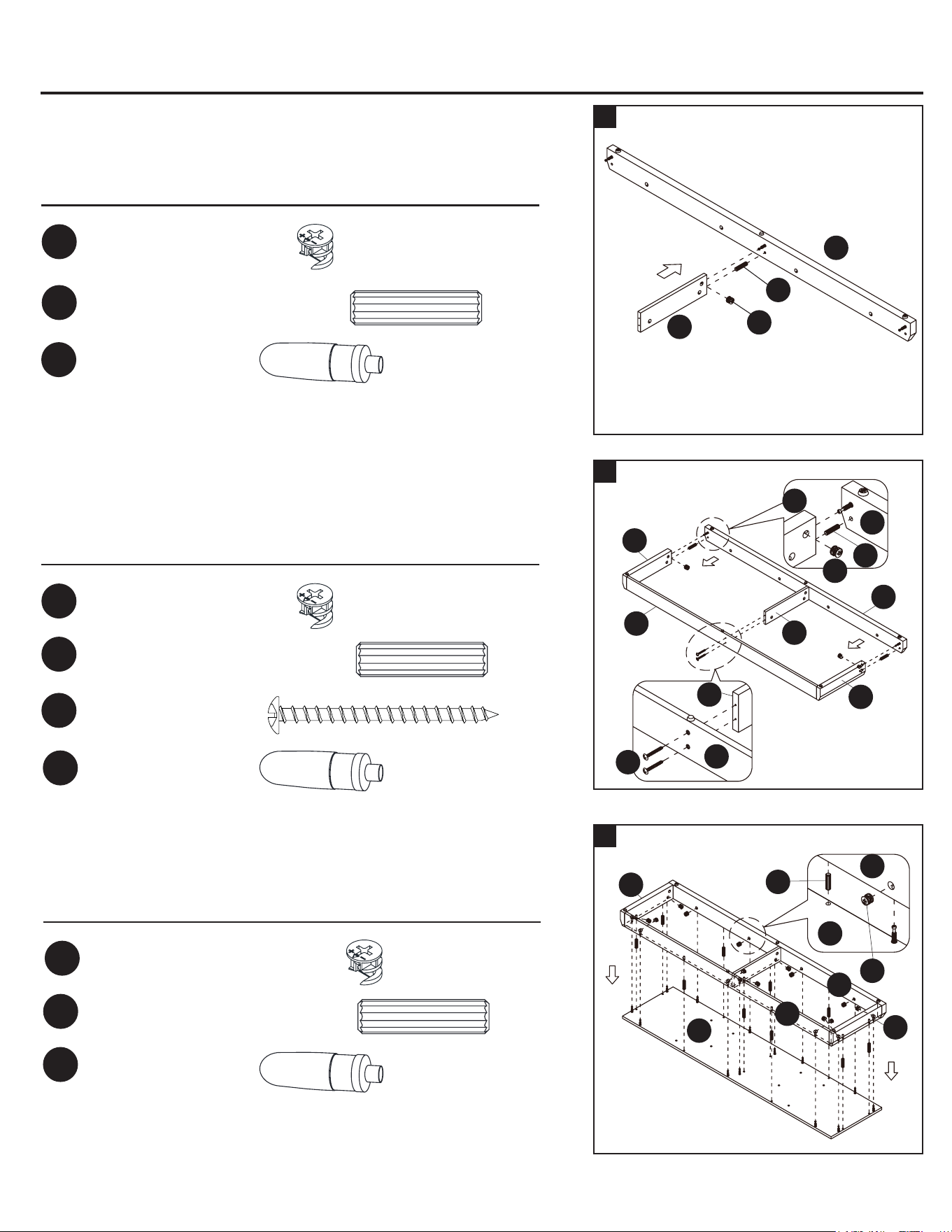
9
INSTRUCCIONES DE ENSAMBLAJE
8
7
O
O
R
P
Q
M
DD
BB
BB
7. Pegue una espiga de madera (DD) en el oricio designado en el
extensor central inferior (R) y fíjelo al travesaño delantero (O) al
enganchar un cerrojo de leva (BB).
BB
Aditamentos utilizados
Espiga de madera de 30 mm x 2
Espiga de madera de 30 mm x 10
Cerrojo de leva x 2
Cerrojo de leva x 13
Tornillo M4 x 50 mm x 2
Tornillo M4 x 50 mm x 4
Tornillo M4 x 50 mm x 4
Pegamento x 1
Pegamento x 1
BB
BB
DD
DD
HH
HH
HH
PP
PP
PP
Aditamentos utilizados
Aditamentos utilizados
8a. Pegue dos espigas de madera de 30 mm (DD) a los oricios laterales
inferiores en los travesaños laterales (P y Q) y fíjelos al travesaño
delantero (O) al enganchar dos cerrojos de leva (BB).
8b. Inserte dos tornillos de 50 mm (HH) a través del travesaño posterior
(N) y atorníllelos de forma segura en el extensor central inferior (R).
9. Pegue las espigas de madera de 30 mm (DD) a los oricios internos
del bastidor de la base y fíjelo al panel inferior (M) al enganchar trece
cerrojos de leva (BB).
INSTRUCCIONES DE ENSAMBLAJE
10
M
M
10a. Pida ayuda para poner la base en posición vertical.
10b. Atornille rmemente siete pernos de leva (CC) en los pequeños
oricios designados en el panel inferior (M). Apriete rmemente con
un destornillador Phillips.
Aditamentos utilizados
Perno de leva x 7
CC
Espiga de madera de 30 mm x 4
Espiga de madera de 30 mm x 6
Pegamento x 1
Pegamento x 1
DD
DD
PP
PP
Aditamentos utilizados
11a. Pegue dos espigas de madera de 30 mm (DD) en los oricios
interiores de cada soporte corto de la cámara de combustión (A1) y
fíjelas al panel inferior (M).
11b. Fije los soportes cortos de la cámara de combustión (A1) al panel
inferior (M) con cuatro tornillos de 50 mm (HH).
12
11
M
HH
A1
A1
HH
HH
HH
DD
DD
DD
M
T
U
HH
HH
DD
DD
Aditamentos utilizados
12a. Pegue seis espigas de madera (DD) de 30 mm a los oricios
interiores de los paneles de separación (T y U) y al soporte largo de
la cámara de combustión (Z).
12b. Alinee los oricios grandes del panel inferior (M) con las espigas
insertadas en los paneles divisorios (T y U) y el soporte largo de la
cámara de combustión (Z), y presiónelos para unirlos.
12c. Inserte cuatro tornillos de 50 mm (HH) a través de los oricios de
montaje en el panel inferior (M) y atorníllelos rmemente en los
paneles divisorios (T y U).
N
N
O
O
R
R
P
P
Q
HH
DD
BB
O
N
M
CC
DD
Z
2928
Espiga de madera de 30 mm x 1
Cerrojo de leva x 1
Pegamento x 1
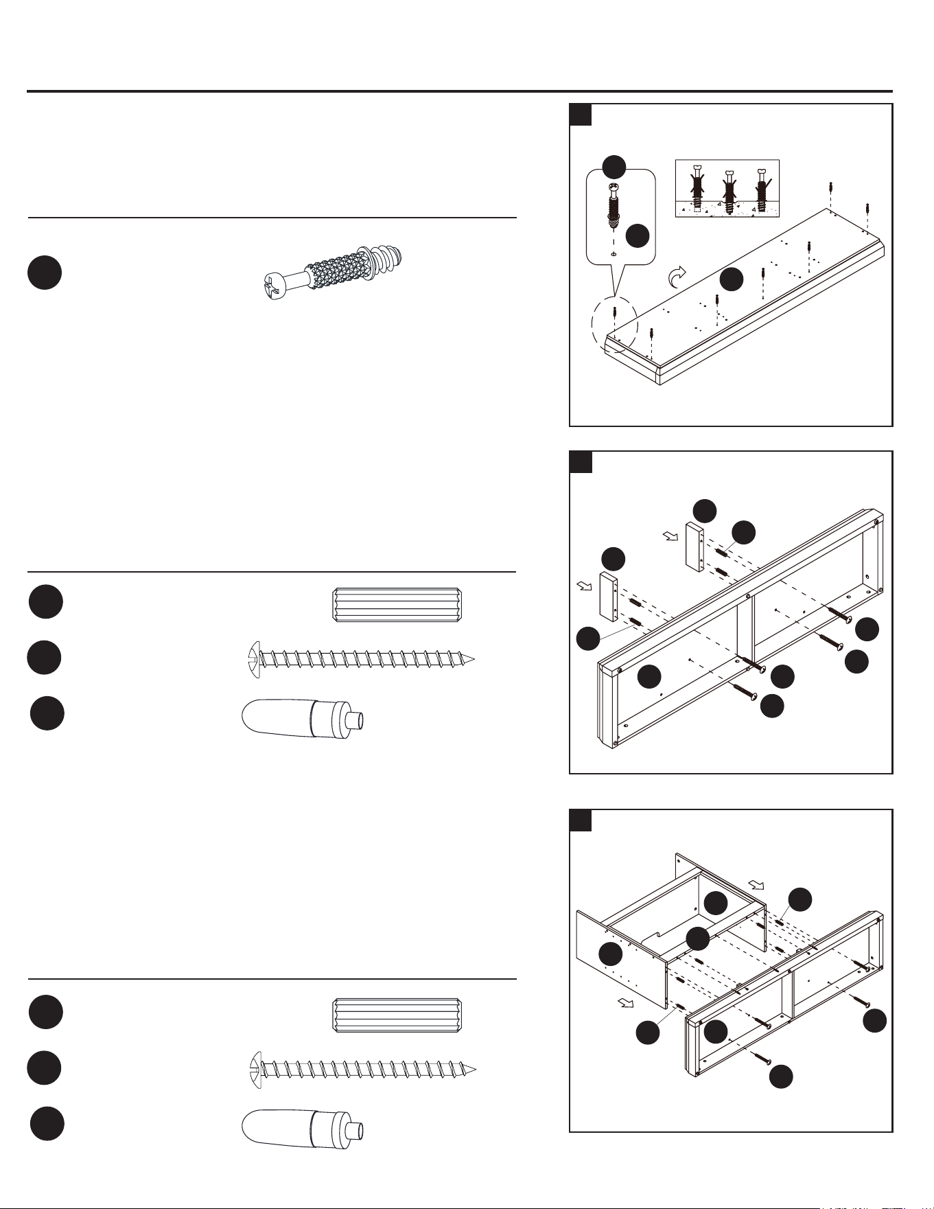
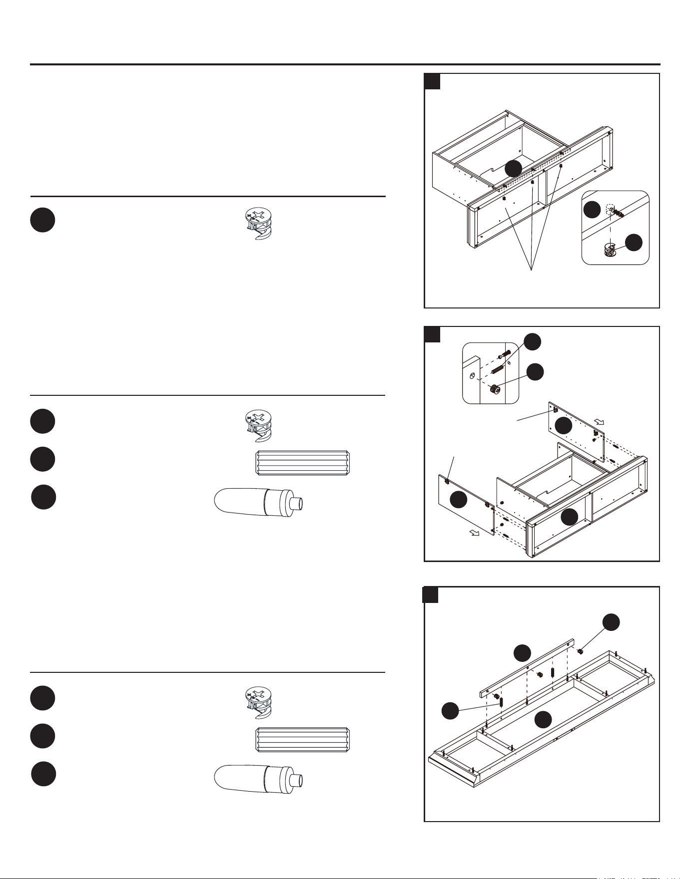
15
16
INSTRUCCIONES DE ENSAMBLAJE
14
13
M
S
S
DD
BB
BB
Aditamentos utilizados
13. Fije el soporte largo de la cámara de combustión (Z) al panel inferior
(M) al enganchar tres cerrojos de leva (BB).
Espiga de madera de 30 mm x 4
Espiga de madera de 30 mm x 8
Espiga de madera de 30 mm x 2
Cerrojo de leva x 4
Cerrojo de leva x 8
Cerrojo de leva x 3
Cerrojo de leva x 3
Pegamento x 1
Pegamento x 1
Pegamento x 1
BB
BB
BB
BB
DD
DD
DD
PP
PP
PP
Aditamentos utilizados
Aditamentos utilizados
Aditamentos utilizados
14. Pegue cuatro espigas de madera de 30 mm (DD) a los oricios
internos inferiores en los paneles laterales (S) y fíjelas al panel inferior
(M) al enganchar cuatro cerrojos de leva (BB).
Las bases de las
bisagras deben
mirar
16a. Pegue ocho espigas de madera (DD) a los oricios interiores
superiores de los paneles verticales (S, T y U).
16b. Pida ayuda para colocar el panel superior (K) en las espigas de
madera insertadas (DD) y fíjelo en su lugar al enganchar ocho
cerrojos de leva (BB).
16c. Ahora, regrese y apriete rmemente todos los cerrojos de leva y
los tornillos. Asegúrese de que todas las piezas estén apretadas y
que no haya espacios entre las piezas. Esto ayudará a mantener
la unidad cuadrada.
K
T
S
S
W
U
DD
BB
INSTRUCCIONES DE ENSAMBLAJE
Aditamentos utilizados
Tornillo con cabeza de arandela x 40
FF
17a. Pida ayuda para voltear el ensamble anterior en sus bordes
frontales.
17b. Levante el panel posterior central (E1) y alinee los oricios
pretaladrados contra el borde largo superior con los oricios guía
en la parte posterior del panel superior (K). Fíjelo en su lugar con el
tornillo con cabeza de arandela proporcionado (FF).
17c. Use los oricios guía para guiarse al alinear y jar los paneles
posteriores laterales (F1) al marco de la repisa para chimenea con
los tornillos con cabeza de arandela (FF).
17
F1
F1
18. Fije una manija (G1) al lado frontal de cada puerta (C1) con los
pernos de manija (OO) proporcionados.
Aditamentos utilizados
Perno de la manija x 4
OO
18
C1
G1
OO
x 2
15. Pegue dos espigas de madera (DD) en los oricios internos de la
moldura frontal superior (W) y fíjelas al panel superior (K) al
enganchar tres cerrojos de leva (BB).
Z
Z
Los cerrojos de leva deben
mirar hacia adentro
K
W
DD
BB
E1
FF
3130
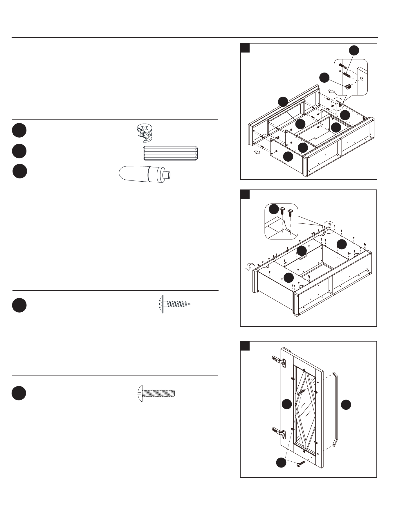
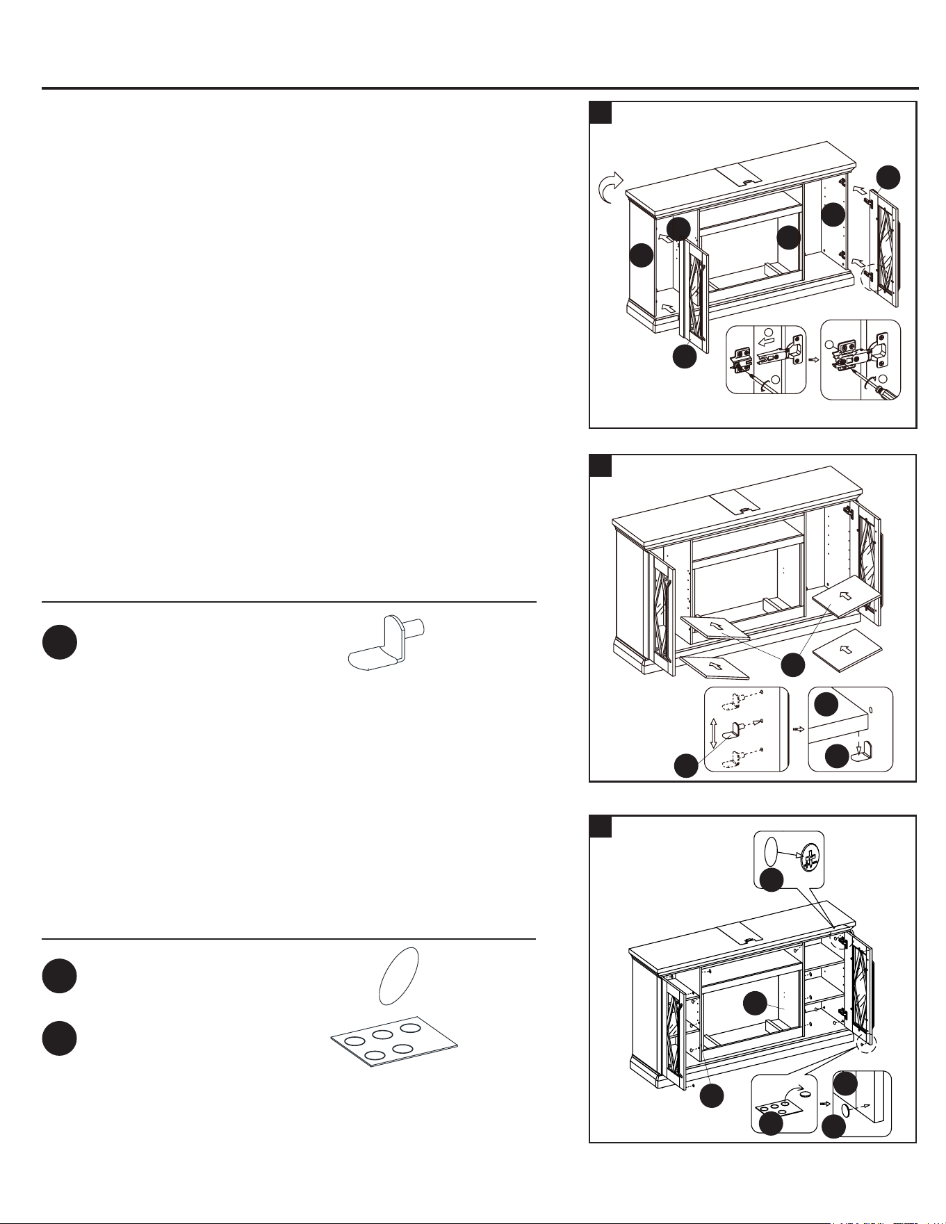
INSTRUCCIONES DE ENSAMBLAJE
INSTRUCCIONES DE ENSAMBLAJE
19a. Pida ayuda para poner la unidad en posición vertical.
19b. Levante una puerta (C1) y je los brazos de bisagra extendidos a las
bases de bisagra instaladas en el panel lateral izquierdo (S). Aoje
el perno en la parte posterior de la base de la bisagra para que
encaje fácilmente. Alinee e inserte la ranura en “U” en el brazo de
la bisagra debajo de la cabeza del perno en la parte posterior de la
base de la bisagra. Asegúrese de que ambas bisagras de la puerta
encajen y funcionen correctamente.
Apriete el perno en la base de la bisagra para bloquear las bisagras
en su lugar.
19c. Repita el mismo proceso para jar la otra puerta (C1) en el lado
opuesto.
19d. Abra y cierre las puertas para asegurarse de que estén alineadas
y cerradas correctamente. Si es necesario, ajuste bien los tornillos.
Consulte la calcomanía de la bisagra en la puerta para ajustarla.
19
S
S
T
U
C1
C1
1
2
1
2
V
V
JJ
JJ
Aditamentos utilizados
Soporte para estante x 16
JJ
20. Inserte ocho soportes para estante (JJ) en los oricios deseados
dentro de cada compartimento lateral. Asegúrese de ubicar los
cuatro soportes para estante en la misma altura para nivelar el
estante. Incline y apoye los estantes ajustables (V) sobre los
soportes para estante (JJ).
21
Aditamentos utilizados
Calcomanía de papel x 18
Amortiguador de goma x 4
KK
LL
21a. Coloque las calcomanías de papel (KK) en los cerrojos de leva y los
tornillos visibles.
21b. Pegue los topes de goma (LL) en las esquinas exteriores de las
puertas donde están en contacto con los paneles de separación
(T y U).
20
Instalación del accesorio para chimenea
22
22a. Consulte la gura A: je los 2 tornillos superiores (AA) a través del
brazo vertical (C) en el calentador (A) hasta que quede apretado.
22b. Consulte la gura B: je los 2 tornillos inferiores (AA) a través del
brazo vertical (C) hasta que esté apretado.
22c. Apriete completamente los 4 tornillos (AA) por última vez.
22d. Repita el mismo proceso con el brazo vertical (B).
NOTA IMPORTANTE: utilice un destornillador manual, no un
destornillador eléctrico para ensamblar el accesorio para chimenea.
Consulte BILT para obtener las instrucciones en video.
ADVERTENCIA: no levante ni transporte el calentador de los brazos
verticales.
Aditamentos utilizados
Tornillo M4 x 10 mm x 8
AA
1
2
IMPORTANTE: siga cuidadosamente los 2 pasos a continuación para
insertar cada leño.
23
23a. Instale el leño izquierdo (F) en el oricio izquierdo del lecho de
brasas (E) al insertar el borde delantero de la base del leño en las
muescas delanteras del oricio del lecho de brasas.
23b. Luego incline el leño hacia atrás para insertar el borde posterior de
la base del leño en las muescas posteriores del oricio del lecho
de brasas (presione rmemente el leño para que encaje en su
posición).
23c. Repita el proceso anterior para el leño derecho (G).
E
E
E
F
F
F
G
24
24a. Coloque el lecho de brasas (E) en el calentador (A) como se
muestra.
24b. Empuje el lecho de brasas hacia delante contra la brida delantera
del calentador.
24c. Coloque el cable USB como se muestra.
T
C1
LL
LL
U
KK
Figura A
Figura B
B
C
C
C
A
A
A
AA
AA
E
E
A
A
USB cable
3332

INSTRUCCIONES DE ENSAMBLAJE
INSTRUCCIONES DE ENSAMBLAJE
19a. Pida ayuda para poner la unidad en posición vertical.
19b. Levante una puerta (C1) y je los brazos de bisagra extendidos a las
bases de bisagra instaladas en el panel lateral izquierdo (S). Aoje
el perno en la parte posterior de la base de la bisagra para que
encaje fácilmente. Alinee e inserte la ranura en “U” en el brazo de
la bisagra debajo de la cabeza del perno en la parte posterior de la
base de la bisagra. Asegúrese de que ambas bisagras de la puerta
encajen y funcionen correctamente.
Apriete el perno en la base de la bisagra para bloquear las bisagras
en su lugar.
19c. Repita el mismo proceso para jar la otra puerta (C1) en el lado
opuesto.
19d. Abra y cierre las puertas para asegurarse de que estén alineadas
y cerradas correctamente. Si es necesario, ajuste bien los tornillos.
Consulte la calcomanía de la bisagra en la puerta para ajustarla.
19
S
S
T
U
C1
C1
1
2
1
2
V
V
JJ
JJ
Aditamentos utilizados
Soporte para estante x 16
JJ
20. Inserte ocho soportes para estante (JJ) en los oricios deseados
dentro de cada compartimento lateral. Asegúrese de ubicar los
cuatro soportes para estante en la misma altura para nivelar el
estante. Incline y apoye los estantes ajustables (V) sobre los
soportes para estante (JJ).
21
Aditamentos utilizados
Calcomanía de papel x 18
Amortiguador de goma x 4
KK
LL
21a. Coloque las calcomanías de papel (KK) en los cerrojos de leva y los
tornillos visibles.
21b. Pegue los topes de goma (LL) en las esquinas exteriores de las
puertas donde están en contacto con los paneles de separación
(T y U).
20
Instalación del accesorio para chimenea
22
22a. Consulte la gura A: je los 2 tornillos superiores (AA) a través del
brazo vertical (C) en el calentador (A) hasta que quede apretado.
22b. Consulte la gura B: je los 2 tornillos inferiores (AA) a través del
brazo vertical (C) hasta que esté apretado.
22c. Apriete completamente los 4 tornillos (AA) por última vez.
22d. Repita el mismo proceso con el brazo vertical (B).
NOTA IMPORTANTE: utilice un destornillador manual, no un
destornillador eléctrico para ensamblar el accesorio para chimenea.
Consulte BILT para obtener las instrucciones en video.
ADVERTENCIA: no levante ni transporte el calentador de los brazos
verticales.
Aditamentos utilizados
Tornillo M4 x 10 mm x 8
AA
1
2
IMPORTANTE: siga cuidadosamente los 2 pasos a continuación para
insertar cada leño.
23
23a. Instale el leño izquierdo (F) en el oricio izquierdo del lecho de
brasas (E) al insertar el borde delantero de la base del leño en las
muescas delanteras del oricio del lecho de brasas.
23b. Luego incline el leño hacia atrás para insertar el borde posterior de
la base del leño en las muescas posteriores del oricio del lecho
de brasas (presione rmemente el leño para que encaje en su
posición).
23c. Repita el proceso anterior para el leño derecho (G).
E
E
E
F
F
F
G
24
24a. Coloque el lecho de brasas (E) en el calentador (A) como se
muestra.
24b. Empuje el lecho de brasas hacia delante contra la brida delantera
del calentador.
24c. Coloque el cable USB como se muestra.
T
C1
LL
LL
U
KK
Figura A
Figura B
B
C
C
C
A
A
A
AA
AA
E
E
A
A
USB cable
3332

INSTRUCCIONES DE ENSAMBLAJE INSTRUCCIONES DE ENSAMBLAJE
25
25a. Doble el panel de pared (H) como se muestra. Luego colóquese en
la parte posterior del calentador (A).
25b. Sostenga el panel de pared (H) en el ángulo que se muestra a
continuación e inserte el borde posterior inferior en las ranuras de
metal de la parte posterior del calentador (A).
25c. Incline el panel de pared (H) hacia delante hasta que la esquina
inferior se inserte en los canales en U inferiores de ambos brazos
verticales (B y C).
25d. Continúe inclinando el panel de pared (H) hacia delante hasta que
la esquina superior se inserte en los canales en U superiores de
ambos brazos verticales (B y C).
B
C
A
H
H
Canal en U
26
26. Enchufe completamente el conector USB del lecho de brasas (E) en
el puerto posterior del calentador (A).
E
A
A
27
27. Deslice el vidrio (I) dentro de los canales en U internos en ambos
brazos verticales (B y C) hasta que el vidrio se asiente sobre el
calentador (A). Si es necesario, empuje la parte superior de los brazos
verticales hacia adentro o hacia afuera para acomodar el vidrio.
Asegúrese de que la parte superior del vidrio (I) esté al ras con la
parte superior de ambos brazos verticales (B y C).
I
I
A
B
C
Las etiquetas de advertencia
en el vidrio
28. Coloque la correa del conector superior (D) sobre el vidrio (I) y los
brazos verticales (B y C). Siga la orientación que se muestra a
continuación.
28
B
C
D
D
H
H
El borde biselado debe
mirar hacia el interior
de la unidad.
29. Sujete la correa del conector (D) a ambos brazos verticales (B y C)
con dos tornillos (AA) como se muestra a continuación. Los oricios
deben estar alineados para que pase el tornillo.
30. La cámara de combustión ahora está lista para el siguiente paso
de ensamblaje.
Aditamentos utilizados
30
29
B
C
H
H
D
D
AA
Tornillo M4 x 10 mm x 2
AA
90
I
3534
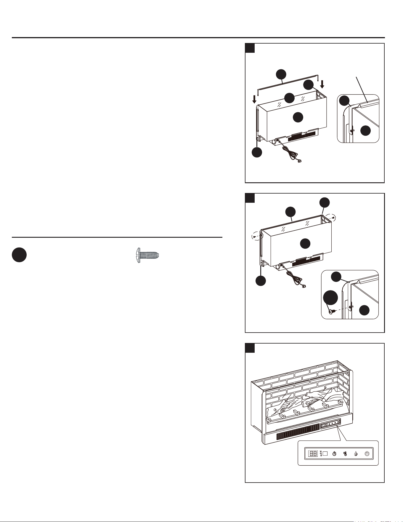
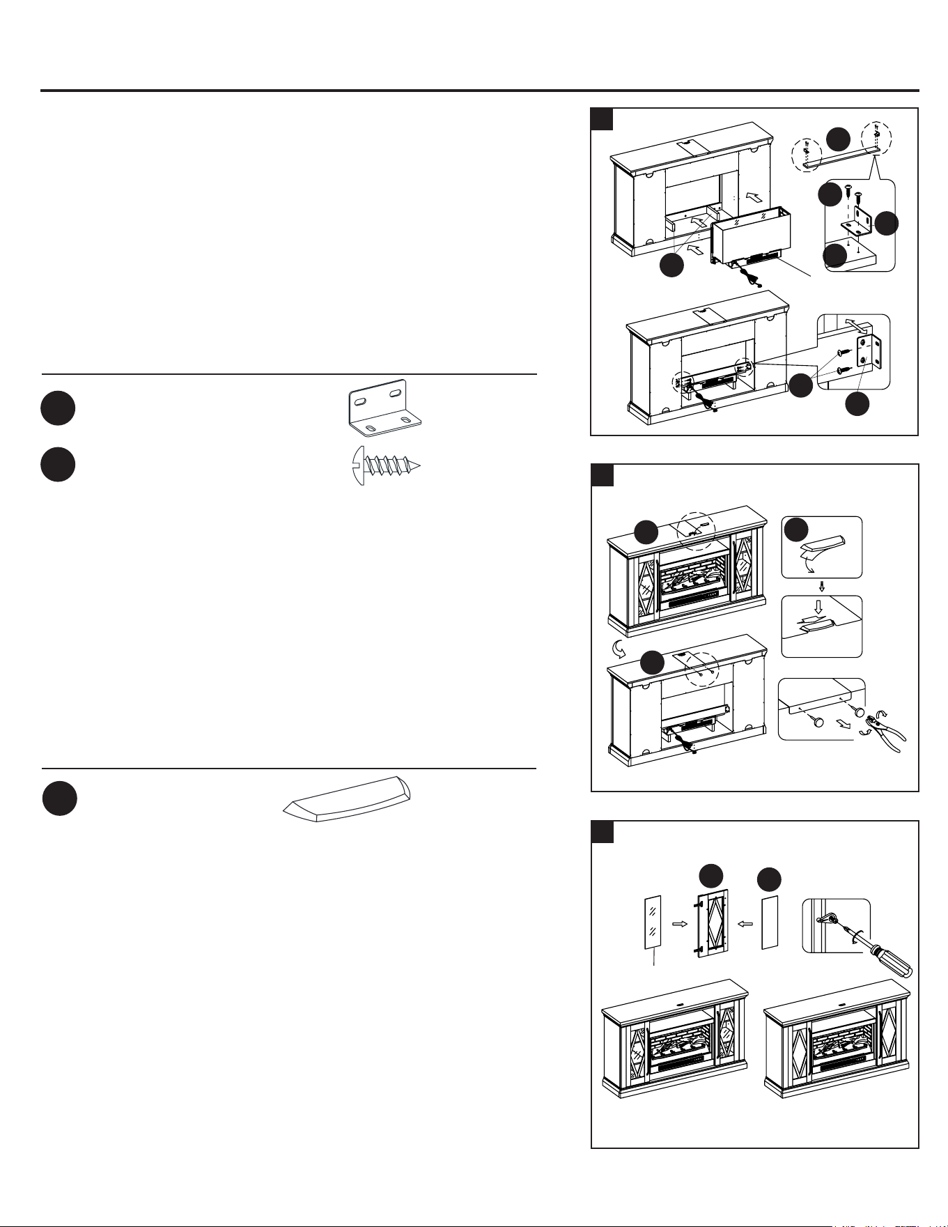
INSTRUCCIONES DE ENSAMBLAJE
INSTRUCCIONES DE ENSAMBLAJE
Aditamentos utilizados
Soporte en forma de L x 2
Tornillo de cabeza plana x 8
MM
II
31a. Levante el accesorio de la chimenea con cuidado sobre los
soportes cortos de la cámara de combustión (A1) y en la parte
posterior de la repisa para chimenea ensamblada, y céntrelo
en la abertura. NO arrastre el accesorio por los soportes
cortos de la cámara de combustión, ya que puede rayarlos.
31b. Utilice los orificios guía como guía, fije dos soportes en forma
de L (MM) en el soporte posterior de la cámara de combustión
(Y) con cuatro tornillos de cabeza alomada (II). Asegúrese de
que el lado del ángulo recto esté al ras con el borde corto del
soporte posterior de la cámara de combustión (Y).
31c. Fije el soporte posterior de la cámara de combustión (Y) entre
los paneles de separación (T y U) con cuatro tornillos (II) y use
los orificios guía como guía.
31
Y
Y
II
MM
A1
Cámara de combustión
eléctrica
MM
32
33
32a. Retire el respaldo de papel del tope acrílico (NN) y luego alinee
correctamente el tope acrílico en el corte de la plantilla del tope
acrílico en el frente del panel superior (K). Presione el tope acrílico
para ayudar a la adhesión.
32b. En la parte posterior del panel superior (K), sujete la cabeza de la
tachuela de plástico con unos alicates. Luego, jale de la tachuela
con un movimiento giratorio para quitar la plantilla del tope acrílico.
NOTA: debe instalar el tope acrílico para evitar que su
televisor se vuelque si coloca uno de pantalla plana en el
panel superior.
Aditamentos utilizados
Tope acrílico
x 1
NN
Siga estos pasos si desea cambiar los paneles de la puerta para
chimenea de vidrio a madera (D1). De lo contrario, vaya al paso “34”.
NOTA: para evitar que su televisor se vuelque, debe instalar el tope
acrílico si coloca un televisor de pantalla plana en el panel superior. De lo
contrario, vaya al paso “32b”.
33a. Tome una puerta (C1) y aoje los tornillos en el interior del marco
para puerta.
33b. Gire los sujetadores para quitar el panel antiguo.
33c. Inserte el nuevo panel, luego gire los sujetadores y apriete los
tornillos para asegurar el panel en el marco para puerta.
33d. Repita este proceso con la otra puerta (C1).
C1
D1
Panel de puerta de vidrio
34
Montante de madera
Tornillo
corto
Conector
Soporte
de metal
Tornillo largoCable de acero
Nivelador
para pisos
Par
34a. Ajuste los niveladores para pisos para nivelar la unidad en su ubicación
deseada contra la pared.
34b. Ahora, siga las instrucciones impresas en la bolsa de plástico que
contiene los aditamentos de contención antivuelcos para jar las
contenciones a la unidad y la pared.
NOTA:
los niños pequeños pueden salir gravemente lesionados
debido a muebles que se vuelcan. Debe instalar aditamentos de
contención antivuelcos con la unidad para evitar que la unidad se
vuelque y cause accidentes o daños. Las contenciones antivuelco
están destinadas solo como elemento disuasorio, no sustituyen la
supervisión adecuada de un adulto. Las contenciones antivuelco no
son contenciones contra terremotos. Si desea agregar la seguridad
adicional de las contenciones contra terremotos, debe comprarlas e
instalarlas por separado.
34c. Conecte la chimenea al transformador de potencia. Siga el manual de
funcionamiento del accesorio para chimenea eléctrica para controlar la
chimenea.
Instalación de los aditamentos de contención antivuelcos
RR
II
NN
K
K
3736
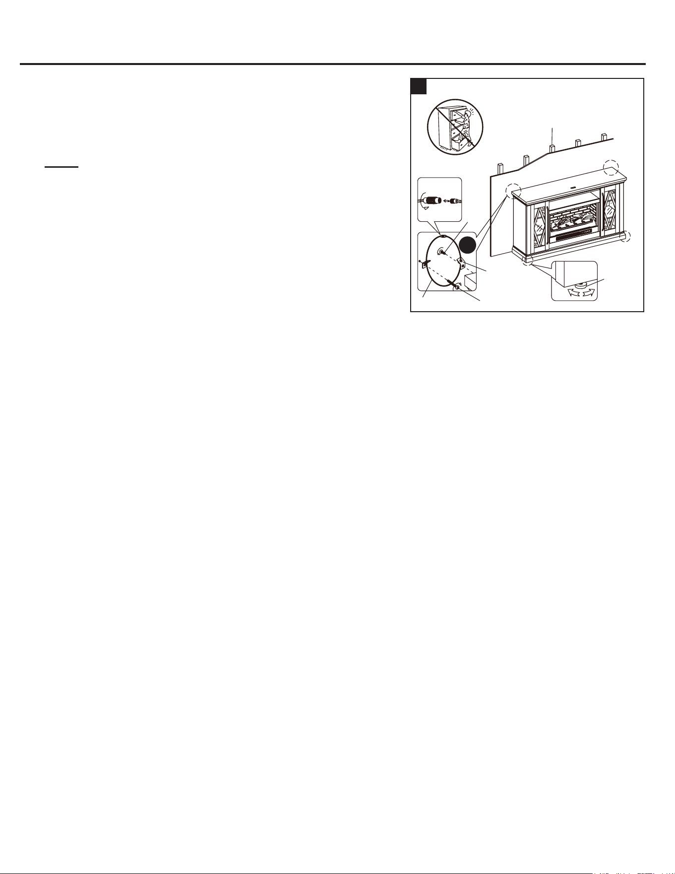
INSTRUCCIONES DE ENSAMBLAJE
INSTRUCCIONES DE ENSAMBLAJE
Aditamentos utilizados
Soporte en forma de L x 2
Tornillo de cabeza plana x 8
MM
II
31a. Levante el accesorio de la chimenea con cuidado sobre los
soportes cortos de la cámara de combustión (A1) y en la parte
posterior de la repisa para chimenea ensamblada, y céntrelo
en la abertura. NO arrastre el accesorio por los soportes
cortos de la cámara de combustión, ya que puede rayarlos.
31b. Utilice los orificios guía como guía, fije dos soportes en forma
de L (MM) en el soporte posterior de la cámara de combustión
(Y) con cuatro tornillos de cabeza alomada (II). Asegúrese de
que el lado del ángulo recto esté al ras con el borde corto del
soporte posterior de la cámara de combustión (Y).
31c. Fije el soporte posterior de la cámara de combustión (Y) entre
los paneles de separación (T y U) con cuatro tornillos (II) y use
los orificios guía como guía.
31
Y
Y
II
MM
A1
Cámara de combustión
eléctrica
MM
32
33
32a. Retire el respaldo de papel del tope acrílico (NN) y luego alinee
correctamente el tope acrílico en el corte de la plantilla del tope
acrílico en el frente del panel superior (K). Presione el tope acrílico
para ayudar a la adhesión.
32b. En la parte posterior del panel superior (K), sujete la cabeza de la
tachuela de plástico con unos alicates. Luego, jale de la tachuela
con un movimiento giratorio para quitar la plantilla del tope acrílico.
NOTA: debe instalar el tope acrílico para evitar que su
televisor se vuelque si coloca uno de pantalla plana en el
panel superior.
Aditamentos utilizados
Tope acrílico
x 1
NN
Siga estos pasos si desea cambiar los paneles de la puerta para
chimenea de vidrio a madera (D1). De lo contrario, vaya al paso “34”.
NOTA: para evitar que su televisor se vuelque, debe instalar el tope
acrílico si coloca un televisor de pantalla plana en el panel superior. De lo
contrario, vaya al paso “32b”.
33a. Tome una puerta (C1) y aoje los tornillos en el interior del marco
para puerta.
33b. Gire los sujetadores para quitar el panel antiguo.
33c. Inserte el nuevo panel, luego gire los sujetadores y apriete los
tornillos para asegurar el panel en el marco para puerta.
33d. Repita este proceso con la otra puerta (C1).
C1
D1
Panel de puerta de vidrio
34
Montante de madera
Tornillo
corto
Conector
Soporte
de metal
Tornillo largoCable de acero
Nivelador
para pisos
Par
34a. Ajuste los niveladores para pisos para nivelar la unidad en su ubicación
deseada contra la pared.
34b. Ahora, siga las instrucciones impresas en la bolsa de plástico que
contiene los aditamentos de contención antivuelcos para jar las
contenciones a la unidad y la pared.
NOTA:
los niños pequeños pueden salir gravemente lesionados
debido a muebles que se vuelcan. Debe instalar aditamentos de
contención antivuelcos con la unidad para evitar que la unidad se
vuelque y cause accidentes o daños. Las contenciones antivuelco
están destinadas solo como elemento disuasorio, no sustituyen la
supervisión adecuada de un adulto. Las contenciones antivuelco no
son contenciones contra terremotos. Si desea agregar la seguridad
adicional de las contenciones contra terremotos, debe comprarlas e
instalarlas por separado.
34c. Conecte la chimenea al transformador de potencia. Siga el manual de
funcionamiento del accesorio para chimenea eléctrica para controlar la
chimenea.
Instalación de los aditamentos de contención antivuelcos
RR
II
NN
K
K
3736

CUIDADO Y MANTENIMIENTO
CUIDADO DEL MUEBLE DE MADERA
LIMPIEZA DEL REBORDE DE LA CHIMENEA
Se proporciona un aplicador de retoque para minimizar pequeños rasguños o rayones que pueden ocurrir durante el ensamble
o el envío. Para limpiar y cuidar su mueble:
• Utilice un paño suave y limpio que no raye la supercie al limpiarla.
• No es necesario usar pulidores de muebles. Si desea utilizar pulidores, debe probarlos primero en un área no visible.
• Usar cualquier tipo de solvente en el mueble puede dañar el acabado.
• Nunca utilice agua para limpiar sus muebles ya que puede provocar daños en el acabado.
• Siempre use posavasos y bases debajo de vasos y macetas.
• Limpie inmediatamente todos los derrames. Utilice un paño suave y limpio para aplicar sobre el derrame suavemente.
Evite frotar.
• Siempre use almohadillas protectoras debajo de platos calientes. El calor puede crear cambios químicos que pueden producir
manchas dentro del acabado del mueble.
• Las manchas o marcas de crayones o marcadores de tinta serán difíciles de limpiar.
• En el caso de que su mueble se tiña o se dañe durante el uso, le recomendamos que llame a un profesional para repararlo.
• Revise periódicamente los tornillos/pernos y apriételos si es necesario.
• Es mejor mantener el mueble en un ambiente climatizado. Los cambios extremos de temperatura y humedad pueden causar
decoloración, deformación, encogimiento y división de la madera. Se recomienda mantenga el mueble lejos de la luz solar
directa, ya que puede provocar daños en el acabado.
• El cuidado y la limpieza adecuados en el hogar prolongarán la vida útil de su compra. Seguir estos importantes y útiles
consejos mejorará sus muebles a medida que envejezcan.
Limpie el reborde de metal con un paño suave levemente humedecido con un producto a base de aceite de cítricos y dé brillo
con un paño suave limpio. NO use pulidores de latón ni limpiadores domésticos, ya que estos productos dañan el reborde de
metal. Los productos a base de aceite de cítricos se pueden obtener en supermercados o ferreterías.
La garantía de este producto es válida para el comprador original. Si esta unidad presenta alguna falla debido a defectos en
los materiales o la mano de obra, el fabricante reemplazará o reparará a su discreción este artículo sin cargos. La garantía
se anula si el producto no se ensambló correctamente y debido al mal uso, abuso por sobrecarga, modicación de cualquier
tipo o daños producidos por un accidente. Esta garantía no es transferible y no cubre el desportillado, desprendimiento,
rayones, oxidación, abolladuras u otros daños en la supercie de este producto. La responsabilidad del fabricante se limita a la
reparación o el reemplazo de este producto. El fabricante no se hará responsable por daños accidentales o resultantes u otros
daños o pérdidas causadas por fallas del producto.
Esta garantía reemplaza a todas las demás garantías explícitas. Algunos estados no permiten la exclusión o limitación de los
daños accidentales o resultantes, de modo que las limitaciones anteriores pueden no aplicarse en su caso. Esta garantía le
otorga derechos legales especícos, y podría tener otros derechos, que varían según el estado.
UN AÑO DE GARANTÍA LIMITADA
LISTA DE PIEZAS DE REPUESTO
Para obtener piezas de repuesto, llame a nuestro Departamento de Servicio al Cliente al 866-439-9800,
de lunes a domingo de 8 a.m. a 8 p.m., hora estándar del Este. También puede ponerse en contacto con
PIEZA DESCRIPCIÓN PIEZA #
A Calentador 00FB30-HLA-IR-A
B Brazo vertical izquierdo 00FB-HLA-B
C Brazo vertical derecho 00FB-HLA-C
D Correa del conector 00FB30-HLA-D
E Lecho de brasas 00FB30-HLA-E
F Leño izquierdo 00FB30-HLA-F
G Leño derecho 00FB30-HLA-G
H Panel de pared de la cámara de combustión 00FB30-HLA-HB
I Vidrio de la cámara de combustión 00FB30-HLA-I
J Control remoto 00RC006B
K Panel superior 00LWFP62-9-K
L Estante para sistema de audio y TV 00LWFP62-9-L
M Panel inferior 00LWFP62-9-M
N Travesaño posterior 00LWFP62-9-N
O Travesaño delantero 00LWFP62-9-O
P Travesaño izquierdo 00LWFP62-9-P
Q Travesaño derecho 00LWFP62-9-Q
R Extensor central inferior 00LWFP62-9-R
S Panel lateral 00LWFP62-9-S
T Panel de separación izquierdo 00LWFP62-9-T
U Panel de separación derecho 00LWFP62-9-U
V Estante ajustable 00LWFP62-9-V
W Moldura frontal superior 00LWFP62-9-W
X Placa perforada central 00LWFP62-9-X
Y Soporte posterior de la cámara de combustión 00LWFP62-9-Y
Z Soporte largo de la cámara de combustión 00LWFP62-9-Z
A1 Soporte corto de la cámara de combustión 00LWFP62-9-A1
B1 Reborde central 00LWFP62-9-B1
C1 Marco para puerta 00LWFP62-9-C1
D1 Accesorio para puertas de madera 00LWFP62-9-D1
E1 Panel posterior central 00LWFP62-9-E1
F1 Panel posterior lateral 00LWFP62-9-F1
G1 Manija con pernos 00LWFP62-9-G1
H1 Accesorio para puertas de vidrio 00LWFP62-9-H1
I1 Bisagra de puerta con tornillos 00LWFP62-9-I1
J1 Nivelador para pisos 00LWFP62-9-J1
K1 Protector para pisos 00LWFP62-9-K1
L1 Sujetador de goma con tornillos 00LWFP62-9-L1
AA Tornillo de accesorio M4 x 10 mm 00FB-HLA-AA
Todos los aditamentos 00LWFP62-9-CH
Impreso en Vietnam
B
A
D
F
G
H
J
I
E
K
Y
X
L
W
S
V
T
M
Z
U
V
S
P
O
R
Q
N
C
E1
I1
D1
D1
C1
B1
B1
F1
J1
K1
L1
AA
A1
C1
G1
F1
H1
3938
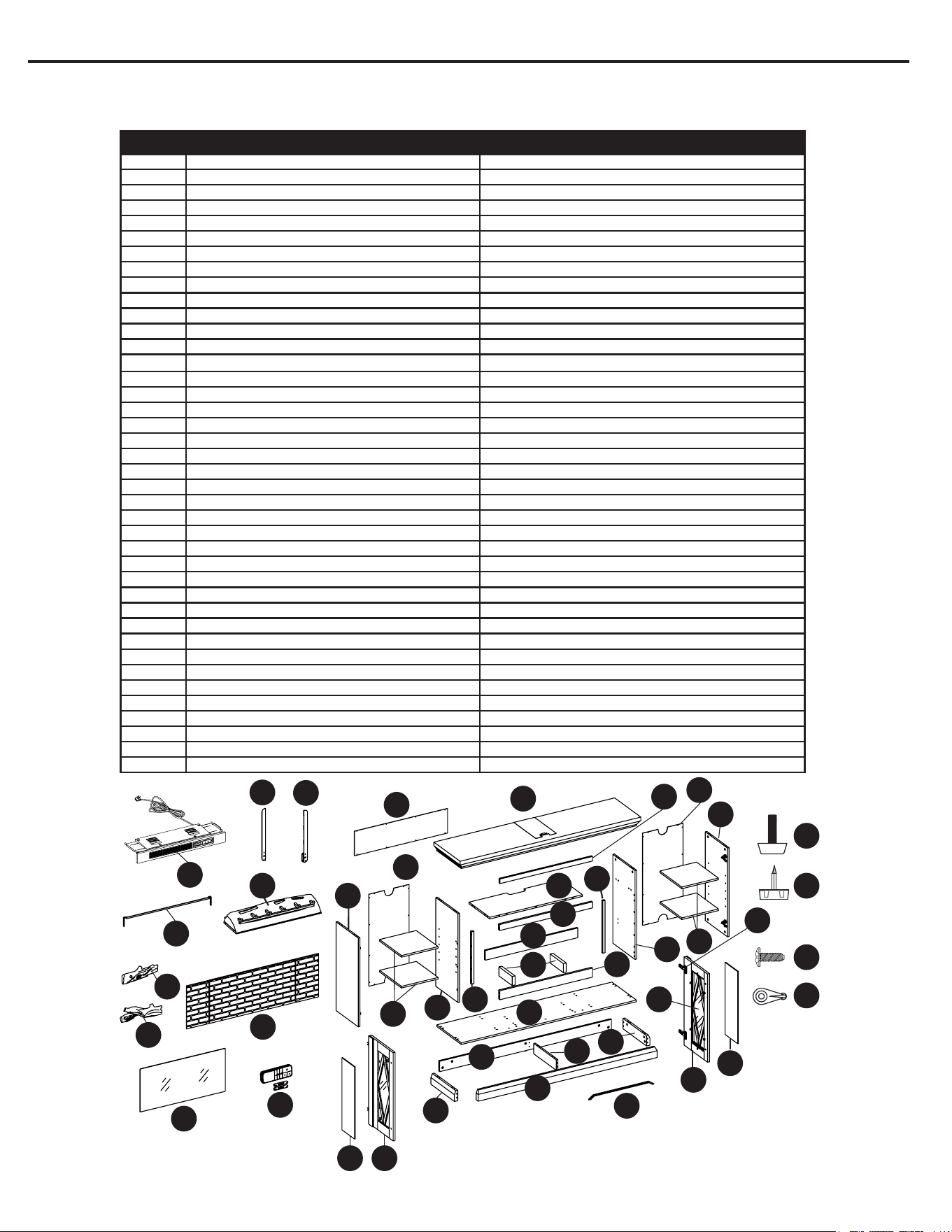
CUIDADO Y MANTENIMIENTO
CUIDADO DEL MUEBLE DE MADERA
LIMPIEZA DEL REBORDE DE LA CHIMENEA
Se proporciona un aplicador de retoque para minimizar pequeños rasguños o rayones que pueden ocurrir durante el ensamble
o el envío. Para limpiar y cuidar su mueble:
• Utilice un paño suave y limpio que no raye la supercie al limpiarla.
• No es necesario usar pulidores de muebles. Si desea utilizar pulidores, debe probarlos primero en un área no visible.
• Usar cualquier tipo de solvente en el mueble puede dañar el acabado.
• Nunca utilice agua para limpiar sus muebles ya que puede provocar daños en el acabado.
• Siempre use posavasos y bases debajo de vasos y macetas.
• Limpie inmediatamente todos los derrames. Utilice un paño suave y limpio para aplicar sobre el derrame suavemente.
Evite frotar.
• Siempre use almohadillas protectoras debajo de platos calientes. El calor puede crear cambios químicos que pueden producir
manchas dentro del acabado del mueble.
• Las manchas o marcas de crayones o marcadores de tinta serán difíciles de limpiar.
• En el caso de que su mueble se tiña o se dañe durante el uso, le recomendamos que llame a un profesional para repararlo.
• Revise periódicamente los tornillos/pernos y apriételos si es necesario.
• Es mejor mantener el mueble en un ambiente climatizado. Los cambios extremos de temperatura y humedad pueden causar
decoloración, deformación, encogimiento y división de la madera. Se recomienda mantenga el mueble lejos de la luz solar
directa, ya que puede provocar daños en el acabado.
• El cuidado y la limpieza adecuados en el hogar prolongarán la vida útil de su compra. Seguir estos importantes y útiles
consejos mejorará sus muebles a medida que envejezcan.
Limpie el reborde de metal con un paño suave levemente humedecido con un producto a base de aceite de cítricos y dé brillo
con un paño suave limpio. NO use pulidores de latón ni limpiadores domésticos, ya que estos productos dañan el reborde de
metal. Los productos a base de aceite de cítricos se pueden obtener en supermercados o ferreterías.
La garantía de este producto es válida para el comprador original. Si esta unidad presenta alguna falla debido a defectos en
los materiales o la mano de obra, el fabricante reemplazará o reparará a su discreción este artículo sin cargos. La garantía
se anula si el producto no se ensambló correctamente y debido al mal uso, abuso por sobrecarga, modicación de cualquier
tipo o daños producidos por un accidente. Esta garantía no es transferible y no cubre el desportillado, desprendimiento,
rayones, oxidación, abolladuras u otros daños en la supercie de este producto. La responsabilidad del fabricante se limita a la
reparación o el reemplazo de este producto. El fabricante no se hará responsable por daños accidentales o resultantes u otros
daños o pérdidas causadas por fallas del producto.
Esta garantía reemplaza a todas las demás garantías explícitas. Algunos estados no permiten la exclusión o limitación de los
daños accidentales o resultantes, de modo que las limitaciones anteriores pueden no aplicarse en su caso. Esta garantía le
otorga derechos legales especícos, y podría tener otros derechos, que varían según el estado.
UN AÑO DE GARANTÍA LIMITADA
LISTA DE PIEZAS DE REPUESTO
Para obtener piezas de repuesto, llame a nuestro Departamento de Servicio al Cliente al 866-439-9800,
de lunes a domingo de 8 a.m. a 8 p.m., hora estándar del Este. También puede ponerse en contacto con
nosotros en [email protected].
PIEZA DESCRIPCIÓN PIEZA #
A Calentador 00FB30-HLA-IR-A
B Brazo vertical izquierdo 00FB-HLA-B
C Brazo vertical derecho 00FB-HLA-C
D Correa del conector 00FB30-HLA-D
E Lecho de brasas 00FB30-HLA-E
F Leño izquierdo 00FB30-HLA-F
G Leño derecho 00FB30-HLA-G
H Panel de pared de la cámara de combustión 00FB30-HLA-HB
I Vidrio de la cámara de combustión 00FB30-HLA-I
J Control remoto 00RC006B
K Panel superior 00LWFP62-9-K
L Estante para sistema de audio y TV 00LWFP62-9-L
M Panel inferior 00LWFP62-9-M
N Travesaño posterior 00LWFP62-9-N
O Travesaño delantero 00LWFP62-9-O
P Travesaño izquierdo 00LWFP62-9-P
Q Travesaño derecho 00LWFP62-9-Q
R Extensor central inferior 00LWFP62-9-R
S Panel lateral 00LWFP62-9-S
T Panel de separación izquierdo 00LWFP62-9-T
U Panel de separación derecho 00LWFP62-9-U
V Estante ajustable 00LWFP62-9-V
W Moldura frontal superior 00LWFP62-9-W
X Placa perforada central 00LWFP62-9-X
Y Soporte posterior de la cámara de combustión 00LWFP62-9-Y
Z Soporte largo de la cámara de combustión 00LWFP62-9-Z
A1 Soporte corto de la cámara de combustión 00LWFP62-9-A1
B1 Reborde central 00LWFP62-9-B1
C1 Marco para puerta 00LWFP62-9-C1
D1 Accesorio para puertas de madera 00LWFP62-9-D1
E1 Panel posterior central 00LWFP62-9-E1
F1 Panel posterior lateral 00LWFP62-9-F1
G1 Manija con pernos 00LWFP62-9-G1
H1 Accesorio para puertas de vidrio 00LWFP62-9-H1
I1 Bisagra de puerta con tornillos 00LWFP62-9-I1
J1 Nivelador para pisos 00LWFP62-9-J1
K1 Protector para pisos 00LWFP62-9-K1
L1 Sujetador de goma con tornillos 00LWFP62-9-L1
AA Tornillo de accesorio M4 x 10 mm 00FB-HLA-AA
Todos los aditamentos 00LWFP62-9-CH
Impreso en Vietnam
B
A
D
F
G
H
J
I
E
K
Y
X
L
W
S
V
T
M
Z
U
V
S
P
O
R
Q
N
C
E1
I1
D1
D1
C1
B1
B1
F1
J1
K1
L1
AA
A1
C1
G1
F1
H1
3938

SG24458
Número de serie
Fecha de compra
2140
Gracias por comprar este producto ALLEN+ROTH.
¿Preguntas, problemas o piezas faltantes?
Antes de volver a la tienda, póngase en contacto al:
866-439-9800, de lunes a domingo de 8 a.m. a 8 p.m., hora estándar del Este; o escriba a [email protected].
ARTÍCULO #5691736
MODELO #LWFP62-9
CHIMENEA PARA SISTEMA DE
AUDIO Y TV DE 157.48 CM
ALLEN + ROTH y el diseño del logotipo son mar-
cas comerciales o marcas registradas de LF, LLC.
Todos los derechos reservados.
ADJUNTE SU RECIBO AQUÍ