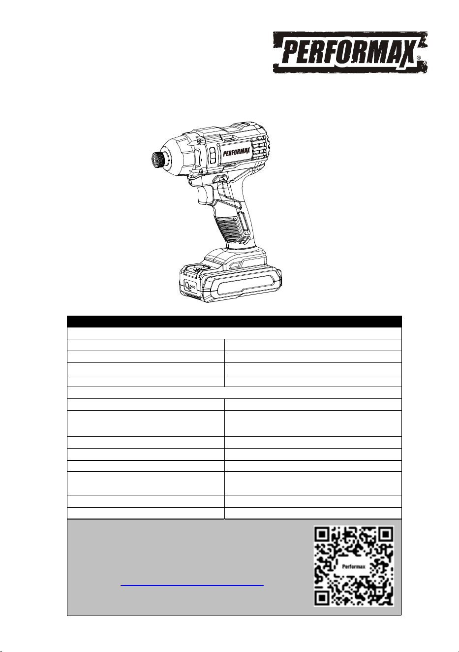
20 VOLT LITHIUM ION IMPACT DRIVER
241-9042
Owner’s Manual
PRODUCT SPECIFICATIONS
IMPACT DRIVER
Variable speed: 0–2800 RPM (no load)
Impact speed: 0-3000 BPM
Torque: 1,400 in/lbs (158 Nm) maximum
Quick release hex drive chuck 1/4" (6.35 mm)
BATTERY & CHARGER
Battery: 20 V, Lithium ion
Charge time: Approx. 100 minutes for 2Ah battery
and 200 minutes for 4Ah battery
Charger input: 100–240V AC, 50–60 Hz
Charger output: 21.5 V DC, 1.5 A
Weight: 3.27 lbs with battery
Need Assistance?
• Technical questions
• Replacement parts
• Parts missing from package
Email us at:
Call us on our toll-free customer support line:1-866-349-8665
(9-5pm Monday-Friday EST)
Replacement battery:
Replacement charger:
Replacement battery&charger kit:
236-9049, 236-9050, 267-3206,
267-3207
236-9051, 267-3002, 267-3205
241-9040
Scan here for support

2
Product specifications ………….……………………………………………………. 1
Table of contents ……………………………………………………………………... 2
General safety warnings …………………………………………………………….. 3–4
Eye, ear & lung protection …………………………………………………………… 3–4
Electrical safety ………………………………………………………………………. 4
Power tool safety ……………………………………………………………………... 5–6
General safety rules ………………………………………………………………….. 5
Work area ………………………………………………………………….………….. 5
Electrical safety ………………………………………………………………………. 5
Personal safety ……………………………………………………………………….. 5–6
Power tool use and care .……………………………………………………………. 6
Battery tool use and care ……………………………………………………………. 6
Service ………………………………………………………………………………… 6
Specific safety rules ………………………………………………………………….. 7
Battery & charger safety ………………………………………………………….…. 8
Battery pack recycling ……………………………………………………………….. 8
Symbols ……………………………………………………………………………….. 9
Know your impact driver …………………………………………………… 10
Assembly and operating …………………………………………………………….. 10–15
Charging the battery pack …………………………………………………………… 10
Installing a battery pack ……………………………………………………… 11
Installing screwdriver bits and sockets …………………………………………... 12
Installing nut drivers for 3/16" to 3/8" nuts ……………………………………... 14
Installing impact sockets for 7/16" to 3/4" nuts ………………………………... 14
Forward/reverse switch ………..………………………………………………….. 12
Variable-speed trigger switch ………………………………………………………. 12
LED worklight
………………………………………………………....................... 13
Driving screws ………………………………………………………....................... 14
Removing nuts ………………………………………………………......................... 15
Preparing screw holes ………………………………………………....................... 13
Maintenance …………………………………………………………………………... 16
Exploded view ………………………………………………………………………… 17
Parts list ……………………………………………………………………………….. 18
Warranty ……………………………………………………………………….……… 19
TABLE OF CONTENTS
3
EYE, EAR & LUNG PROTECTION
This instruction manual includes the following:
General Safety Warnings
Specific Safety Rules and Symbols
Functional Description
Assembly
Operation
Maintenance
!
ALWAYS WEAR EYE PROTECTION THAT CONFORMS WITH CSA
REQUIREMENTS or ANSI SAFETY STANDARD Z87.1
FLYING DEBRIS can cause permanent eye damage. Prescription
eyeglasses ARE NOT a replacement for proper eye protection.
WARNING: Non-compliant eyewear can cause serious injury if
broken during the operation of a power tool.
WARNING: Use hearing protection, particularly during extended
periods of operation of the tool, or if the operation is noisy.
!
GENERAL SAFETY WARNINGS
WARNING: Before using this tool or any of its accessories, read this
manual and follow all Safety Rules and Operating Instructions. The important
precautions, safeguards and instructions appearing in this manual are not
meant to cover all possible situations. It must be understood that common
sense and caution are factors which cannot be built into the product.
!
SAVE THESE INSTRUCTIONS FOR REFERENCE
4
ELECTRICAL SAFETY
GENERAL SAFETY WARNINGS
WEAR A DUST MASK THAT IS DESIGNED TO BE USED WHEN
OPERATING A POWER TOOL IN A DUSTY ENVIRONMENT.
WARNING: Dust that is created by power sanding, sawing, grinding,
drilling, and other construction activities may contain chemicals that are
known to cause cancer, birth defects, or other genetic abnormalities. These
chemicals include:
Lead from lead-based paints
Crystalline silica from bricks, cement, and other masonry products
Arsenic and chromium from chemically treated lumber
The level of risk from exposure to these chemicals varies, according to how
often this type of work is performed. In order to reduce exposure to these
chemicals, work in a we
ll-ventilated area, and use approved safety
equipment, such as a dust mask that is specifically designed to filter out
microscopic particles.
!
WARNING: To avoid electrical hazards, fire hazards or damage to the
tool, use proper circuit protection.
This tool charger is wired at the factory for 120 V AC operation. It must be
connected to a 120 V AC, 15 A circuit that is protected by a time-delayed
fuse or circuit breaker. To avoid shock or fire, replace power cord
immediately if it is worn, cut or damaged in any way.
SAVE THESE INSTRUCTIONS FOR REFERENCE

5
WARNING: Read all safety warnings
and instructions. Failure to follow the warnings
and instructions may result in electric shock, fire
and/or serious injury.
Save all warnings and instructions for future
reference.
Work area safety
Keep work area clean and well lit. Cluttered or
dark areas invite accidents.
Do not operate power tools in explosive
atmospheres, such as in the presence of
flammable liquids, gases or dust. Power tools
create sparks which may ignite the dust or
fumes.
Keep children and bystanders away while
operating a power tool. Distractions can cause
you to lose control.
Electrical safety
Power tool plugs must match the outlet.
Never modify the plug in any way. Do not
use any adap
ter plugs with earthed
(grounded) power tools. Unmodified plugs and
matching outlets will reduce risk of electric
shock.
Avoid body contact with earthed or
grounded surfaces such as pipes, radiators,
ranges and refrigerators. There is an
increased risk of electric shock if your body is
earthed or grounded.
Do not expose power tools to rain or wet
conditions. Water entering a power tool will
increase the risk of electric shock.
Do not abuse the cord. Never use the cord
for carrying, pulling or unplugging the power
tool. Keep cord away from heat, oil, sharp
edges or moving parts. Damaged or
entangled cords increase the risk of electric
shock.
When operating a power tool outdoors, use
an extension cord suitable for
outdoor use.
Use of a cord suitable for outdoor use reduces
the risk of electric shock.
If operating a power tool in a damp location
is unavoidable, use a residual current device
(RCD) protected supply. Use of a ground fault
circuit interrupter (GFCI) reduces the risk of
electric shock.
Personal safety
Stay alert, watch what you are doing and use
common sense when operating a power tool.
Do not use a power tool while you are tired
or under the influence of drugs, alcohol or
medication. A moment of inattention while
operating power tools may result in serious
personal injury.
Use personal protective equipment. Always
wear eye protection. Protective equipment
such as dust mask, non-skid safety shoes, hard
hat, or he
aring protection used for appropriate
conditions will reduce personal injuries.
Prevent unintentional starting. Ensure the
switch is in the off-position before
connecting to power source and/or battery
pack, picking up or carrying the tool.
Carrying power tools with your finger on the
switch or energizing power tools that have the
switch on invites accidents.
Remove any adjusting key or wrench before
turning the power tool on. A wrench or a key
left attached to a rotating part of the power tool
may result in personal injury.
Do not overreach. Keep proper footing and
balance at all times. This enables better
control of the power tool in unexpected
situations.
Dress properly. Do not wear loose clothing
or jewelry. Keep
your hair, clothing and
gloves away from moving parts. Loose
clothes, jewelry or long hair can be caught in
moving parts.
Do not let familiarity gained from frequent use
of tools allow you to become complacent and
ignore tool safety principles. A careless action
can cause severe injury within a fraction of a
second.
If devices are provided for the connection of
dust extraction and collection facilities,
ensure these are connected and properly
used. Use of dust collection can reduce dust-
related hazards.
POWER TOOL SAFETY
!

Keep handles and grasping surfaces dry,
clean and free from oil and grease. Slippery
handles and grasping surfaces do not allow for
safe handling and control of the tool in unexpect-
ed situations.
Do not use a battery pack or tool that is
damaged or modified. Damaged or modified
batteries may exhibit unpredictable behavior
resulting in fire, explosion or risk of injury.
Do not expose a battery pack or tool to fire or
excessive temperature. Exposure to fire or
temperature above 113°F (45°C) may cause
explosion.
Follow all charging instructions and do not
charge the battery pack or tool outside the
temperature range specified in the instruc-
tions. Charging improperly or at temperatures
outside the specified range may damage the
battery and increase the risk of fire.
6
PERSONAL SAFETY – cont’d
Power tool use and care
Do not force the power tool. Use the correct
power tool for your application. The correct
power tool will do the job better and safer at the
rate for which it was designed.
Do not use the power tool if the switch does
not turn it on and off. Any power tool that
cannot be controlled with the switch is
dangerous and must be repaired.
Disconnect the plug from the power source
and/or the battery pack from the power tool
before making any adjustments, changing
accessories, or storing power tools. Such
preventive safety measures reduce the risk of
starting the power tool accidentally.
Store idle power tools out of the reach of
children and do not allow persons u
nfamiliar
with the power tool or these instructions to
operate the power tool. Power tools are
dangerous in the hands of untrained users.
Maintain power tools. Check for
misalignment or binding of moving parts,
breakage of parts and any other condition
that may affect the power tool’s operation. If
damaged, have the power tool repaired
before use. Many accidents are caused by
poorly maintained power tools.
Keep cutting tools sharp and clean. Properly
maintained cutting tools with sharp cutting
edges are less likely to bind and are easier to
control.
Use the power tool, accessories and tool bits
etc. in accordance with these instructions,
taking into account the working conditions
and the work to be performed. Use of the
power tool for operations different from those
intended could resu
lt in a hazardous situation.
Hold power tool by insulated gripping
surfaces, because the blade may contact its
own cord. Cutting a "live" wire may make
exposed metal parts of the tool "live" and could
give the operator an electric shock.
Battery tool use and care
Recharge only with the charger specified by
the manufacturer. A charger that is suitable for
one type of battery pack may create a risk of fire
when used with another battery pack.
Use power tools only with specifically
designated battery packs. Use of any other
battery packs may create a risk of injury and
fire.
When battery pack is not in use, keep it away
from other metal objects, like paper clips,
coins, keys, nails, screws or other small
metal objects that can make a connection
fro
m one terminal to another. Shorting the
battery terminals together may cause burns or a
fire.
Under abusive conditions, liquid may be
ejected from the battery; avoid contact. If
contact accidentally occurs, flush with water.
If liquid contacts eyes, additionally seek
medical help. Liquid ejected from the battery
may cause irritation or burns.
Service
Have your power tool serviced by a qualified
Never service damaged battery packs.
Service of battery packs should only be
performed by the manufacturer or authorized
service providers.
repair person using only identical
replacement parts. This will ensure that the
safety of the power tool is maintained.
POWER TOOL SAFETY

7
Always wear eye protection. Any
power tool can throw foreign
objects into your eyes and cause
permanent eye damage.
ALWAYS wear safety goggles (not glasses) that
comply with ANSI safety standard Z87.1.
Everyday glasses have only impact resistant
lenses. They ARE NOT safety glasses.
WARNING: Glasses or goggles not in
compliance with ANSI Z87.1 could cause
serious injury when they break.
Always check to make sure the area whe
re
screws are being driven or where holes are
being drilled does not have any hidden wiring.
Contact with a "live" wire will make exposed
metal parts of the tool “live” and could result in
an electric shock to the operator.
Do not drive screws or break into existing walls
or other blind areas where electrical wiring may
exist. If this situation is unavoidable, remove all
fuses or disconnect all breakers feeding the
work area.
Secure the workpiece in a vice or with clamps.
Never hold it in your hand or across your legs.
The rotating action of the driver may cause the
bit to come loose from the screw and cause
injury.
Never carry the cordless driver with your finger
on the switch. The tool is always in an "ON"
condition when the battery is charged.
Never hold the body of the cordless driver near
the switch while changing bits. Accidentally
tou
ching the switch may start the tool and
possibly cause an injury.
Always use the correct shape of screwdriver bit
that matches the head of the screw.
Always use the largest size screwdriver bit that
will properly fit into the head of the screw.
Do not use worn or damaged screwdriver or drill
bits. Worn or damaged screwdriver bits will not
drive the screw properly and may jump out of
the screw head, causing
possible injury and
damage to the workpiece. Worn drill bits will not
drill properly and may cause the tool to
overheat.
Always insert the bit fully into the quick release
hex drive chuck and make sure it is properly
locked into the quick release hex drive chuck. A
loose bit holder may jump out of the chuck and
cause damage to the workpiece or possible
injury.
SPECIFIC SAFETY RULES
SAVE THESE INSTRUCTIONS FOR REFERENCE
!
WARNING: To avoid fire or toxic
reaction, never use gasoline, naphtha,
acetone, lacquer thinner or similar highly
volatile solvents to clean the tool.
!
WARNING: Use only accessories
that are recommended for this cordless
impact driver Follow the instructions that
accompany the accessories. The use of
improper accessories may result in injury
to the operator or damage to the tool.
!
WARNING: If any part is missing or
damaged, do not install the battery into
the tool or install any accessory until the
missing or damaged part is replaced.
!
WARNING: Know your cordless impact
driver. Do not plug in the charger or install
the battery in the tool until you have read
and understand this Instruction Manual.
Learn the tool’s applications and limita-
tions, as well as the specific potential
hazards related to this tool.
Following this
rule will reduce the risk of electric shock, fire, or
serious injury.
!

8
WARNING:
Only use the charger
supplied with this kit to charge Perfor-
max® and Yardworks® 20V battery
236-9049, 236-9050, 267-3206, 267-3207,
other types of batteries may burst causing
personal injury and damage.
Do not store or carry the battery in a manner in
which metal objects could contact the exposed
metal end. Do not place the battery in aprons,
pockets, drawers, etc. with loose nails, screws,
keys etc. The battery could short circuit causing
a fire, personal injury or damage to the battery.
Never attempt to open the battery for any
reason. If the housing of the battery breaks or
cracks, immediately discontinue use and do not
recharge.
Do not charge the battery if it is wet or shows
any evidence of corrosion.
A small leakage from the battery may occur
under extreme usage, charging or temperature
conditions. This does not indicate a failure.
However, if the outer seal is broken and this
leakage gets on your ski
n, follow these steps:
1. Wash immediately with soap and water.
2. Neutralize with a mild acid such as lemon
juice or vinegar.
3. If liquid gets into your eyes, flush
immediately with clean water for a
minimum of 10 minutes and seek medical
attention.
NOTE: The battery liquid is slightly acidic.
Do not incinerate the battery. It can explode in a
fire.
Do not use an extension cord. Plug the charger
cord directly into an electrical outlet.
Use the charger only in a standard
120V, 60 Hz electrical outlet.
Do not use the charger in wet or damp
conditions. It is intended for indoor use only.
Do not use the charger near sink
Do not immerse the charger in water. Do not
allow the cord to hang over the edge of a
BATTERY & CHARGER SAFETY
SAVE THESE INSTRUCTIONS FOR REFERENCE
!
table or counter or touch hot surfaces. The
charger should be placed away from sinks and
hot surfaces.
Do not operate charger if the cord or plug is
damaged. Replace the damaged cord and plug
immediately.
Do not operate the charger if it has received a
sharp blow, been dropped or otherwise
damaged in any way. Have a qualified
technician examine the charger and repair it if
necessary. Do not disassemble the charger.
Do NOT charge the batteries when the work
area or the battery temperature is at or below
32°F (0°C) or above 113°F (45°C).
Unplug the charger when not in use and before
cleaning or maintenance.
BATTERY PACK RECYCLING
To preserve our natural resources, please
recycle or dispose of batteries properly.
The batteries charged by this charger may
contain chemicals and metals that are harmful
to the environment. Never dispose of rechargeable
batteries in your normal household garbage or in
landfill s
ites as they will add to the pollution of
the environment.
Please call 1-800-822-8837 for the location of
your nearest RBRC battery recycling location.
9
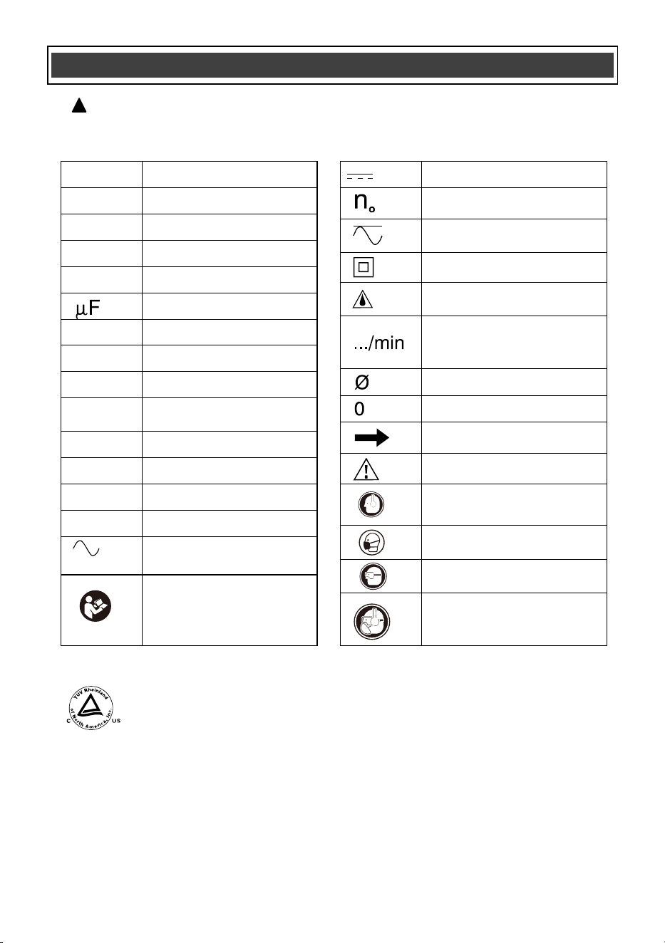
SYMBOLS
WARNING: Some of the following symbols may appear on the cordless impact driver.
Study these symbols and learn their meaning. Proper interpretation of these symbols
will allow for more efficient and safer operation of this tool.
!
This symbol designates that this tool is listed with U.S.
requirements by TÜV Rheinland (Shanghai) Co., Ltd.
Conforms to UL Std. 62841-1 and 62841-2-2.
Certified to CAN/CSA Std. C22.2 No. 62841-1 and 62841-2-2.
JD8706
Wear hearing protection.
Wear eye protection.
Wear breathing protection.
Read instruction manual.
To reduce the risk of
injury, user must read
instruction manual.
V
Volts
A
Amperes
Hz
Hertz
W
Watts
kW
Kilowatts
Microfarads
kg
Kilograms
H
Hours
N/cm
2
Newtons per square
centimeter
Pa
Pascals
OPM
Oscillations per minute
Min
Minutes
S
Seconds
or a.c.
Alternating current
Direct current
No load speed
Alternating or direct
current
Class II construction
Splash-proof
construction
Revolutions or
reciprocations per
minute
Diameter
Off position
Directional Arrow
Warning symbol
Wear hearing protection.
Wear breathing protection.
Wear eye protection.
or DC
lbs
Pounds, Weight
10
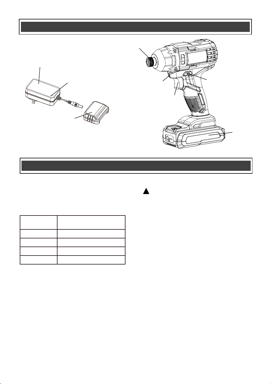
KNOW YOUR IMPACT DRIVER
Quick release hex
drive chuck
Forward /
reverse switch
Battery
Variable speed
trigger switch
LED work-light
Battery charger adapter
Charging status
indicator light
Battery charger cap
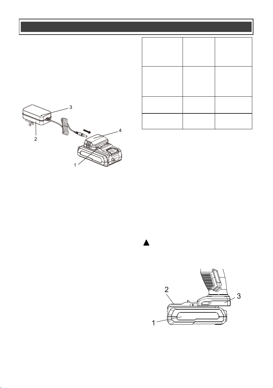
ASSEMBLY AND OPERATING
CHARGING THE BATTERY PACK
WARNING: Do not use the charger
outdoors or expose it to wet or damp
conditions. Water entering the charger will
increase the risk of electric shock.
NOTICE: Lithium-Ion battery packs are
shipped partially charged. Before using it
the first time, you must fully charge it.
NOTICE: You can only charge one battery at
a time with the charger provided.
1. Plug the battery charger adapter into the
battery charger cap and then plug the adapter
(2) into a power supply (120V~60Hz). The
charging status indicator LED light (3) will turn
green indicating that the charger is working
correctly.
2. Align the raised ribs of the battery (1) with the
battery-mounting slots in the battery charge
cap (4); slide the cap onto the battery. If
installed correctly the charging status indicator
light on the charger will turn red indicating the
battery is charging (see chart on this page) and
the battery charge level indicator lights on the
battery will flash.
!
BATTERY CHARGE LEVEL INDICATOR LIGHTS
To check the battery charge level, press the
push button on the battery pack. The LED
indicator lights will show the current charge
levels as indicated in chart below.
NOTE:
If one indicator light begins to flash, the battery
charge level is under 10% capacity and should
be recharged soon.
If three indicator lights begin to flash at a rate of
1 or 2 times per second, the battery is too hot,
and cool the battery till its temperature drops
below 152°F (67°C).
If three indicator lights begin to flash at a rate of
5 times per second, the battery is defective,
please recycle or dispose of batteries properly,
or contact Customer Service.
Indicator
Lights
3 lights on
2 lights on
1 light on
1 light flashing
Battery Charge Level
70%<Charge Level≤100%
40%<Charge Level≤70%
10%<Charge Level≤40%
Charge Level ≤10%
11
ASSEMBLY AND OPERATING
Fig. 2
INSTALLING THE BATTERY PACK IN THE
DRILL/DRIVER
1. Remove the discharged battery pack (1)
from the tool by pressing the battery
release button (2) on the front of the
battery pack and pulling the battery pack
out of the tool handle (3) (Fig. 2).
2. Insert the fully charged battery pack into
the matching slots in the tool handle where
the discharged battery pack has been
removed.
NOTE: The battery release button will
“click” into place when the battery pack is
fully installed.
WARNING: Do not immerse battery
pack in water. Sudden cooling could cause a
hot battery to explode or leak.
!
Charging
status
indicator light
Green NO
Charger
connected
to power
supply
Red YES
Battery is
being charged
Green YES
Battery fully
charged
Charger cap
installed on
battery
Charging
Status
CHARGING THE BATTERY CONT’D
3. When the battery is fully charged the light on
the charger will turn green and the lights on the
battery will turn off or keeps on. Once the
charge cap is removed from the battery (never
check while charging cap is installed on the
battery) you may confirm the charge status of
the battery. When fully charged all battery
charge level indicator lights should be lit.
NOTE:
The battery cannot be correctly charged on
the charger if the battery pack is too hot or
too cold and not within normal temperature
range 41°F (5°C) - 113°F (45°C). Allow the
battery pack to reach normal temperature,
and charging will begin.
The battery pack will fully charge if left on
the charger, but it will not overcharge.
A significantly reduced runtime after fully
charging the battery pack indicates that the
batteries are nearing the end of their usable
life and must be replaced.
The charger may become warm during
charging. This is a normal part of its
operation. Always charge in a well-ventilated
area.
If the battery pack is completely discharged
and no LEDs flash when it is connected to
the charger, this indicates a malfunctioning
battery. In this case, do not attempt to
charge the battery.
Fig. 1
12
FORWARD/REVERSE SWITCH
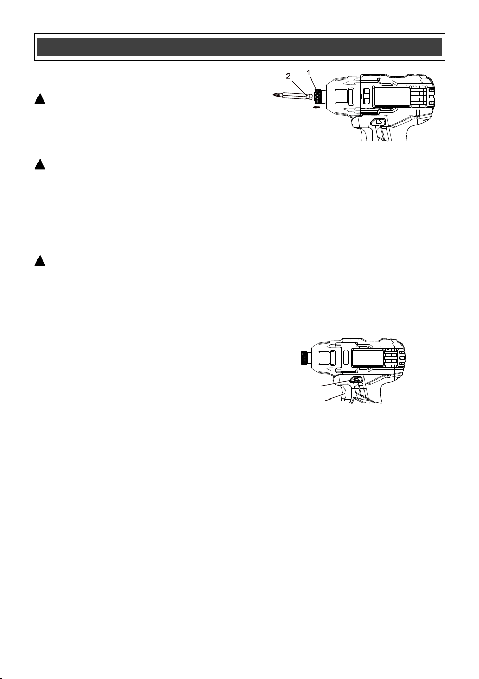
INSTALLING SCREWDRIVER BITS
AND SOCKETS
ASSEMBLY AND OPERATING
NOTES:
a) Use the largest size screwdriver bit that will
properly fit the screw head.
b) Make sure the screwdriver bit is in good
condition and is neither damaged nor worn.
1. Pull outward on the quick release chuck (1)
(Fig. 3).
2. Insert the grooved end of the bit (2) into
the quick release chuck (1) of the tool.
NOTES:
a) Always use ANSI single ended screwdriver
bits or nut driver with the grooved end. These
bits will be properly held in place by the
quick release chuck. Other bit types cannot
be properly secured in the chuck.
b) Push the screwdriver bit as far as it will go
into the quick release chuck.
3. Release the quick release chuck.
4. Pull outward on the screwdriver bit to
ensure it is properly locked into the quick
release chuck.
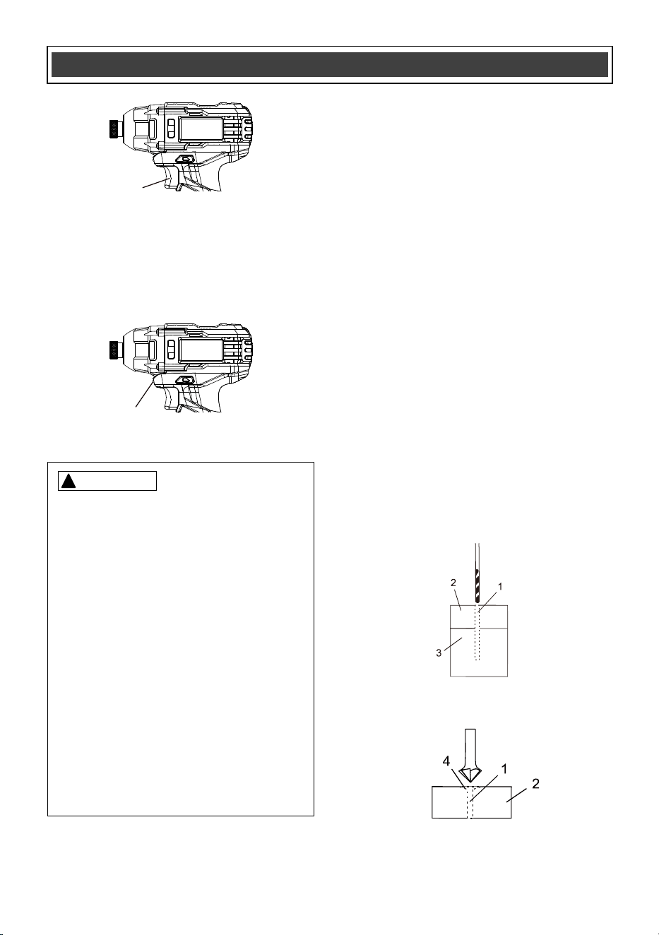
The forward/reverse switch (1) is conveniently
mounted above the trigger switch (2) (Fig. 4).
To make the impact driver rotate clockwise for
driving screws, push the forward/reverse switch
to the left. To make the driver rotate counter-
clockwise for removing screws, push the
forward/reverse switch to the right.
NOTES:
a) Never change the position of the forward/
reverse switch while the quick release chuck
is turning.
b) The trigger switch will NOT function with the
forward/reverse switch in the middle position.
VARIABLE SPEED TRIGGER SWITCH
This impact driver is equipped with a
variable-speed ON/OFF trigger switch.
1. To start the impact driver, gently
squeeze the trigger switch (2) (Fig. 5).
NOTE: The impact driver will turn at its
slowest speed when the trigger switch is
squeezed lightly. The impact driver will
turn at its fastest speed when the trigger
switch is squeezed firmly.
2. To stop the impact driver, release the
trigger switch.
NOTE: Operating the impact driver at
a slow speed for an extended period of
time may cause the impact driver motor
or the battery to overheat. If the driver
gets hot, stop operating it and allow it
to cool for at least 15 minutes.
WARNING: Never hold the impact driver
with your fingers near the switch while
changing the screwdriver bits. Accidentally
touching the switch may start the tool and
possibly cause an injury.
!
WARNING: Always remove the
battery from the tool before changing
any sockets, bits or accessories. You
may injure your hand if the tool is
started accidentally.
!
WARNING: Use only screwdriver bits,
sockets that are designed for use with an
impact driver. Do not use chrome plated
sockets and accessories. Chrome plated
sockets and accessories are designed for
hand use only and MUST NOT be used with
an impact driver. They may shatter and
possibly cause serious injury.
!
Fig. 3
Fig. 4
1
2
13
ASSEMBLY AND OPERATING
1. Clamp the components that are to be
screwed together in their desired position
(Fig. 7).
2. Drill a pilot hole (1) through the outer piece
(2) and into the inner piece (3). Drill hole
2/3 the diameter of the smooth portion of
the screw shank.
NOTE: If the wood is soft, drill the hole 2/3 the
length of the screw. If the wood is hard, drill the
hole the full length of the screw.
3. Remove the clamp from the two pieces to
be screwed together.
4. Enlarge the hole (1) in the outer piece
(2) so it is the same size as the smooth
portion of the screw shank (Fig. 8).
5. If using a flat head screw, counter-sink the
hole (4) so the head of the screw will be
flush with the surface when fully driven into
place.
LED WORKLIGHT
The LED worklight (3) will automatically turn
ON when the trigger switch is squeezed (Fig. 6).
It will automatically turn OFF when the trigger
switch is released.
PREPARING SCREW HOLES
It is important to prepare screw holes before
attempting to fasten two pieces of wood
together. Proper preparation will make screws
drive easier and prevent misaligned compo-
nents, stripped screw heads, splitting and
separating of wood components.
Fig. 7
Fig. 8
Fig. 5
Fig. 6
WARNING:
!
For safety reasons, the operator must
read the sections of this Owner’s Manual
entitled "GENERAL SAFETY
WARNINGS", "POWER TOOL SAFETY",
"SPECIFIC SAFETY RULES", "BATTERY
AND CHARGER SAFETY" and "SYM-
BOLS" before using this impact
driver.
Verify the following every time the
impact driver is used:
1. Safety glasses and hearing
protection are being worn.
2. Socket or accessory is "impact"
rated.
3. Socket or accessory is in good
condition.
Failure to observe these safety rules will
significantly increase the risk of injury.
3
2
WARNING: Nut drivers, socket
adaptor and sockets MUST be impact
rated and include the ANSI locking
groove.
!
14
ASSEMBLY AND OPERATING
This impact driver may be used with nut drivers
and impact sockets. Although these accessories
are NOT included with this tool, they may be
purchased separately.
1. Select the correct screwdriver bit for the
screw being driven and install it in the
quick release chuck (Fig. 3).
2. Set forward/reverse switch to "forward"
(Fig. 4).
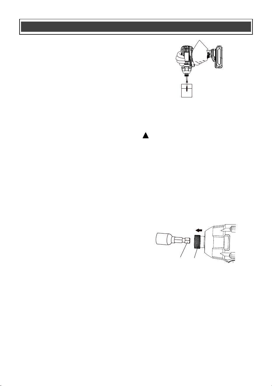
3. Insert the screwdriver bit fully into the
screw head (Fig. 9).
4. While holding the screwdriver bit firmly
against the screw and the bit aligned
with the screw, squeeze the trigger switch
to start the cordless driver and drive the
screw.
5. When the screw is driven to the correct
depth, release the switch and the impact
driver will stop.
NOTE: As the screw is driven into the wood, the
torque required to completely drive the screw
into the wood will increase. The impact function
will allow you to continue driving the screw until
it is fully nested in the countersunk area.
6. Release the trigger as soon as the screw
is driven to the desired depth. Failure to
release the trigger at this point will result
in an overdriven screw and possibly twist
the head off the screw.
NOTE: To remove screws, follow the same
general procedure as for driving screws.
7. Push the forward/reverse button to the
RIGHT for removing screws.
8. Insert the bit fully into the screw head.
9. Hold the impact driver and bit firmly
against the screw head and squeeze the
trigger switch.
NOTE: The impact action will allow you to
remove tight screws.
DRIVING SCREWS
When driving screws, care must be taken to use
a bit that correctly fits the head of the screw
being driven. Make sure you use the largest bit
size that will properly fit into the head of the
screw. The bits must also be in good condition
and not worn so they will drive screws without
slipping out of the screw head.
INSTALLING NUT DRIVERS FOR 3/16" to
3/8" NUTS
1. Select the correct nut driver size.
2. Insert the hex end (1) into the chuck (2)
(Fig. 10).
NOTE: See Fig. 3 for complete procedure.
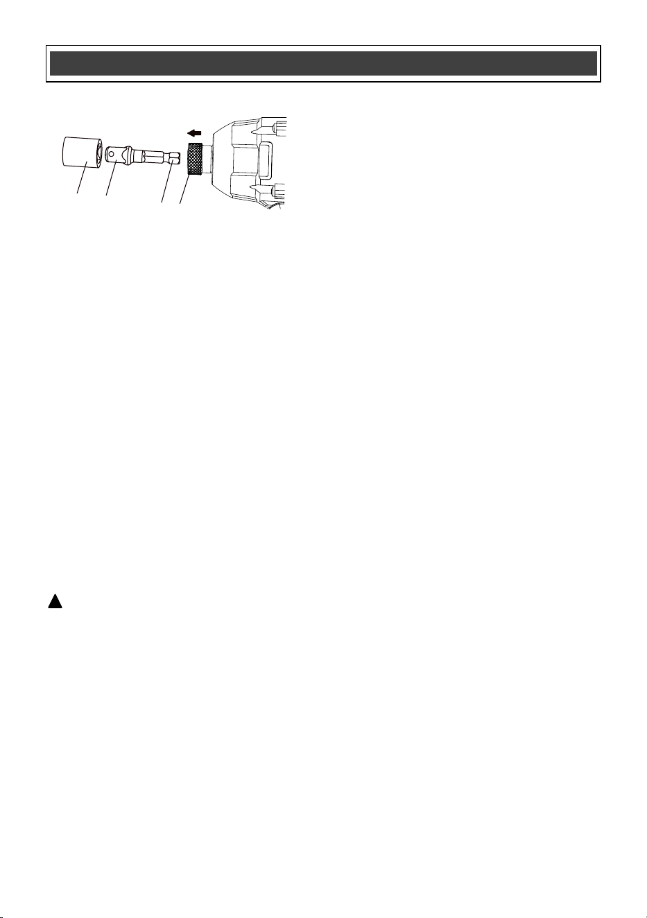
INSTALLING IMPACT SOCKETS FOR 7/16" to
3/4" NUTS
1. Insert the hex end of the socket adapter
(1) into the quick release chuck (2) (Fig. 11).
2. Select the correct socket size.
3. Push the square end of the socket (3) onto
the matching square end of the adaptor (4).
NOTE: Make sure the socket is fully installed
onto the square portion of the adapter.
Fig. 10
Fig. 9
1
2
WARNING: Operating the impact
driver for more than 5 seconds at a time
on a seized or "frozen" fastener will
place severe stress on the impact
driver and cause damage. It may also
break the fastener.
!
REMOVING NUTS
1. Press the forward/reverse button to the
RIGHT for removing nuts (Fig. 4).
2. Place the socket fully onto the nut.
3. Hold the nut driver socket and impact
driver firmly against the nut with both
hands. With the nut driver aligned with the
nut, squeeze the trigger switch to start the
impact driver and remove the nut.
NOTE: When removing fasteners, do not
allow the impact driver to operate more than
5 seconds unless the fastener begins to turn.
If the fastener fails to turn within 5 seconds,
reverse the direction of rotation and operate
the impact driver in a forward direction on
the fastener for a few seconds. Now switch
back to reverse direction and remove the
fastener. This procedure will usually break
loose seized or "frozen" fasteners.
Fig. 11
15
ASSEMBLY AND OPERATING
2
1
4
3

16
GENERAL
WARNING: When servicing, use only
identical replacement parts. The use of any
other part may create a hazard or cause
product damage.
DO NOT use solvents when cleaning plastic
parts. Plastics are susceptible to damage from
various types of commercial solvents and may
be damaged by their use. Use a clean cloth to
remove dirt, dust, oil, grease etc.
WARNING: Do not allow brake fluids,
gasoline, petroleum-based products,
penetrating oils, etc. to come into contact
with plastic parts. They contain chemicals
that can damage, weaken or destroy plastic.
DO NOT abuse power tools. Abusive practices
can damage the tool and the workpiece.
WARNING: DO NOT attempt to modify
tools or create accessories. Any such
alteration or modification is misuse and
could result in a hazardous condition leading
to possible serious injury. It will also void
the warranty.
LUBRICATION
All of the bearings in this tool are lubricated with
a sufficient amount of high-grade lubricant for
the life of the unit under normal conditions.
Therefore, no further lubrication is required.
BATTERY PACK REMOVAL AND
PREPARATION FOR RECYCLING
To preserve our natural resources, please
recycle or dispose of batteries properly.
The batteries accompanying this tool may
contain chemicals and metals that are harmful
to the environment. Never dispose of
rechargeable batteries in your normal household
garbage or in landfill sites, because they will add
to the pollution of the env
ironment.
Consult your local waste authority for
information regarding available recycling and
disposal options.
WARNING: Upon removal of the battery
pack, cover the terminals of the battery pack
with electrical tape or heavy-duty adhesive
tape. Never touch both terminals with metal
objects or body parts, because a short
circuit may result. Keep away from children.
Do not attempt to destroy or disassemble
battery pack or remove any of its
components. Rechargeable batteries must
be recycled or disposed of properly. Failure
to comply with these warnings could result
in fire and serious injury.
MAINTENANCE
!
!
!
!
17
WARNING: When servicing, use only original equipment replacement parts. The use of any
other parts may create a safety hazard or cause damage to the impact driver.
Any attempt to repair or replace electrical parts on this multi-function power tool may create a safety
hazard unless repairs are performed by a qualified technician. For more information, call the Toll-free
Helpline, at 1-866-349-8665.
!
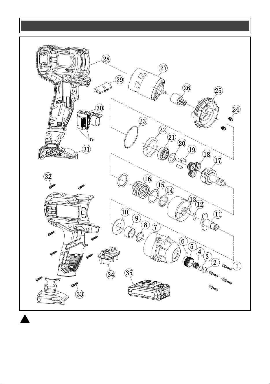
AVAILABLE PARTS

Always order by PART number, not key number.
18
Key # Part # Part Name
1 4030010263 Tapping screw ST3.9x25
2 2050080131 Shaft circlip
3 2030020001 Small washer (1)
4 2050060004 Spring
5 2040170007 Collet sleeve
6 4080030001 Steel ball, dia. 3.5
7 2020050097 Head housing
8 3140020166 O-ring seal
9 2010080157 Shaft collar
10 2030020034 Washer
11 2040050182 Out shaft
12 4080070001 Steel ball, dia. 5.5
13 2040200018 Impact block
14 4080040001 Steel ball, dia. 4
15 2030020035 Washer
16 2050060178 Torsion spring
17 2040050181 Inner shaft
18 2010010148 Planet gear
19 4110050003 Pin dia. 6 x15.5
20 2030020316 Washer
21 4010010062 Bearing 6902Z
22 2010090088 Ring gear
23 3140020167 Sealing ring
24 4020010143 Screw M4x8
25 3150090068 Motor flange
26 2010180064 Motor
27 1030060001 Motor
28 3010020055 Housing
29 3120030151 FWD/REV lever
30 1062010041 Switch
31 3150130199 Foot
32 4030010034 Tapping screw ST2.9x16
33 4030010106
Tapping screw ST3.9x19
34 3150170032 Contact plate
35 1290090062 Battery
AVAILABLE PARTS

2
Rev 2.1 28/08/2025
Distributed by: Menard, Inc., Eau Claire, WI 54703
PERFORMAX
®
20 VOLT IMPACT DRIVER WARRANTY
19
2-YEAR LIMITED WARRANTY:
This PERFORMAX
®
brand power tool carries a 2-Year Limited Warranty to the
original purchaser. If, during normal use, this PERFORMAX
®
power tool breaks
or fails due to a defect in material or workmanship within two (2) years from the
date of original purchase, simply bring this tool with the original sales receipt
back to your nearest MENARDS® retail store. At its discretion, PERFORMAX
®
agrees to have the tool or any defective part(s) repaired or replaced with the
same or similar PERFORMAX
®
product or part free of charge, within the stated
warranty period, when returned by the original purchaser with original sales
receipt. Not withstanding the foregoing, this limited warranty does not cover any
damage that has resulted from abuse or misuse of the Merchandise. This
warranty: (1) excludes expendable parts including but not lim
ited to blades,
brushes, belts, bits, light bulbs, and/or batteries; (2) shall be void if this tool is
used for commercial and/or rental purposes; and (3) does not cover any losses,
injuries to persons/property or costs. This warranty does give you specific legal
rights and you may have other rights, which vary from state to state. Be careful,
tools are dangerous if improperly used or maintained. Seller’s employe
es are
not qualified to advise you on the use of this Merchandise. Any oral
representation(s) made will not be binding on seller or its employees. The rights
under this limited warranty are to the original purchaser of the Merchandise and
may not be transferred to any subsequent owner. This limited warranty is in lieu
of all warranties, expressed or implied including warranties or merchantability
and fitness for a particular
purpose. Seller shall not be liable for any special,
incidental, or consequential damages. The sole exclusive remedy against the
seller will be for the replacement of any defects as provided herein, as long as
the seller is willing or able to replace this product or is willing to refund the
purchase price as provided above. For insurance purposes, seller is not allowed
to demonstrate any of these power tools for you.
Fo
r questions / comments, technical assistance or repair parts –
Please Call Toll Free at: 1-866-349-8665 (M-F 9am-5pm EST)
SAVE YOUR RECEIPTS. THIS WARRANTY IS VOID WITHOUT THEM.
or email